Embed Size (px)
Citation preview
MANUAL SPIERINGS TRUCK AT5
AT5-UK-030626 01-12-09 I
Introduction
This manual is put together to provide the user of the Spierings truck, model AT5, with information about this truck's construction, operation and maintenance.
The driver must have a driving license for driving a heavy truck and have sufficient technical knowledge.
The AT5 truck is built to serve as carriage for the Spierings folding crane, model SK598. For operation, technical data and maintenance of this folding crane we refer to the subjoined manual.
Because the AT5 is provided with five axles, of which 3 axles are steered, excellent mobility is guaranteed on the work site as well as on the road. The axles are hydro-pneumatically suspended, whereas the height can be adjusted and/or blocked. Three axles are driven by a 12.6 litres DAF diesel engine and a gearbox with sixteen gears forward and two gears reverse. After the gearbox is a high/low gear shift (transfer case), which has two different gears and a neutral. A gear for driving on the road and a gear for driving off the road. Neutral serves for the generator drive by the high/low gear shift PTO.
Furthermore, there is a hydraulic system for operating the crane's outrigger system and, when the crane is not equipped with a separate engine on the upper frame, the truck has a 400 Volt generator to provide the crane with the necessary power.
The following items are dealt with in this manual.
General data. In this chapter you will find a description of the measurements and technical specifications.
Location and explanation of controls.
Operating the AT5. This chapter gives you instructions for optimal use of the truck.
Maintenance of the AT5, maintenance schedules as well as explanation of the maintenance work to be carried out. You will also find a maintenance plan containing the specification of the used parts and lubricants.
Specification of drive line and steering system parts
Explanation of the hydraulic, pneumatic and electrical system.
You will find the outline drawings and diagrams referred to at the back of this manual in the enclosures.
Due to the continuous product development at Spierings Kranen the descriptions and pictures may not be all together similar to the condition on your vehicle.
Copyright 2003. No part of this publication may be reproduced or published, in any form or in any way, by print, photo print, microfilm or any other means without prior permission from the manufacturer.

MANUAL SPIERINGS TRUCK AT5
AT5-UK-030626 01-12-09 II
Table of contents
Introduction .......................................................................................................................................... I
Table of contents ................................................................................................................................ II
1. General data AT5 ..................................................................................................................... 1-1
2. Operation .................................................................................................................................. 2-1 2.1. Get to know the truck ..................................................................................................... 2-1 2.2. Truck cab ....................................................................................................................... 2-4 2.3. Control Panel ................................................................................................................. 2-7 2.4. Driving the Spierings crane .......................................................................................... 2-16
2.4.1. Starting .......................................................................................................... 2-16 2.4.2. Driving off ....................................................................................................... 2-17 2.4.3. Change gear .................................................................................................. 2-17 2.4.4. Stopping ......................................................................................................... 2-18 2.4.5. Turning off the engine .................................................................................... 2-18
2.5. Driving off the road ....................................................................................................... 2-18 2.5.1. Off the road gear shift High/Low transfer case ............................................... 2-18 2.5.2. Longitudinal differential lock ........................................................................... 2-19 2.5.3. Transverse differential lock ............................................................................ 2-19 2.5.4. Hydraulic driven axle 1................................................................................... 2-19
2.6. Braking system ............................................................................................................ 2-20 2.6.1. Operating brake ............................................................................................. 2-20 2.6.2. Parking brake ................................................................................................. 2-20 2.6.3. Vacuum brake/engine stop ............................................................................ 2-20 2.6.4. Slowing down using the retarder (optional) .................................................... 2-20
2.7. Parking ......................................................................................................................... 2-21 2.8. Driving with a trailer ..................................................................................................... 2-21 2.9. Towing the crane ......................................................................................................... 2-22
2.9.1. Tow free ......................................................................................................... 2-22 2.9.2. Towing ........................................................................................................... 2-22
2.10. Independent rear axle steering .................................................................................... 2-23 2.11. Driving with erected tower ............................................................................................ 2-24 2.12. Axle height adjustment ................................................................................................. 2-25
3. Maintenance ............................................................................................................................. 3-1 3.1. General .......................................................................................................................... 3-1 3.2. Safety ............................................................................................................................. 3-1
3.2.1. Engine.............................................................................................................. 3-1 3.2.2. Moving components ......................................................................................... 3-1 3.2.3. Oils and coolant ............................................................................................... 3-1 3.2.4. Welding ............................................................................................................ 3-1 3.2.5. Environment ..................................................................................................... 3-2 3.2.6. Cleaning of components .................................................................................. 3-2
3.3. Maintenance plan truck AT5 .......................................................................................... 3-3
4. Periodic checks ....................................................................................................................... 4-1 4.1. Daily checks ................................................................................................................... 4-1
4.1.1. Check engine oil level ...................................................................................... 4-1 4.1.2. Check coolant level .......................................................................................... 4-1 4.1.3. Tyres and rims ................................................................................................. 4-2 4.1.4. Lighting and controls ........................................................................................ 4-2

MANUAL SPIERINGS TRUCK AT5
AT5-UK-030626 01-12-09 III
4.2. Weekly checks ............................................................................................................... 4-2 4.2.1. Check for leaks (oil, air, coolant) ...................................................................... 4-2 4.2.2. Windscreen washer fluid level ......................................................................... 4-2 4.2.3. Clutch fluid level ............................................................................................... 4-2 4.2.4. Draining air vessels ......................................................................................... 4-3 4.2.5. Draining and bleeding fuel system water separator ......................................... 4-3
5. Lubrication ............................................................................................................................... 5-1 5.1. Central lubricating system .............................................................................................. 5-1 5.2. Manual lubrication .......................................................................................................... 5-3
5.2.1. Outrigger-cylinders .......................................................................................... 5-3 5.2.2. Gear change mechanism ................................................................................. 5-3 5.2.3. Driven axles ..................................................................................................... 5-3 5.2.4. Cardan shafts .................................................................................................. 5-4 5.2.5. Steering system ............................................................................................... 5-5
6. The drive system ..................................................................................................................... 6-1 6.1. The diesel engine .......................................................................................................... 6-2
6.1.1. Specification diesel engine .............................................................................. 6-2 6.2. Maintenance plan diesel engine .................................................................................... 6-2
6.2.1. Maintenance activities First service interval ..................................................... 6-2 6.2.2. Maintenance activities X service interval ......................................................... 6-3 6.2.3. Maintenance activities Y service interval ......................................................... 6-3
6.3. Carrying out maintenance work diesel engine ............................................................... 6-3 6.3.1. Change engine oil ............................................................................................ 6-3 6.3.2. Oil Filter Replacement ..................................................................................... 6-3 6.3.3. Air cleaner cleaning/replacement ..................................................................... 6-4 6.3.4. Fuel filter replacement ..................................................................................... 6-4 6.3.5. Change filter element water separator ............................................................. 6-5 6.3.6. Changing coolant ............................................................................................. 6-5
6.4. Inspections ..................................................................................................................... 6-6 6.4.1. Check for fuel leaks ......................................................................................... 6-6 6.4.2. Check components and hose connections for leaks ........................................ 6-6 6.4.3. Radiator and intercooler element inspection/cleaning ..................................... 6-6 6.4.4. Cooling system hoses and air inlet system inspection ..................................... 6-6 6.4.5. Check outlet system for connection and leaks ................................................. 6-6 6.4.6. Check coolant antifreeze concentration ........................................................... 6-7
6.5. The clutch and gearbox ................................................................................................. 6-7 6.5.1. Specification gearbox ...................................................................................... 6-7 6.5.2. Fluid torque converter ...................................................................................... 6-7 6.5.3. Bridging clutch ................................................................................................. 6-8 6.5.4. Freewheel clutch .............................................................................................. 6-8 6.5.5. Retarder ........................................................................................................... 6-9 6.5.6. Clutch .............................................................................................................. 6-9
6.6. Carrying out maintenance work gearbox and clutch ...................................................... 6-9 6.6.1. Bleeding Gearbox ............................................................................................ 6-9 6.6.2. Drain oil gearbox ............................................................................................ 6-10 6.6.3. Filling gearbox and converter with oil ............................................................. 6-10 6.6.4. Change / clean oil filter .................................................................................. 6-10 6.6.5. Take off and replace the suction filter ............................................................ 6-11 6.6.6. Clutch bleeding .............................................................................................. 6-11 6.6.7. Check clutch .................................................................................................. 6-11
6.7. The transfer case ......................................................................................................... 6-12 6.7.1. Specification transfer case ............................................................................. 6-12
6.8. Carrying out maintenance work transfer case .............................................................. 6-12 6.8.1. Bleeding ......................................................................................................... 6-12 6.8.2. Check oil level ................................................................................................ 6-12

MANUAL SPIERINGS TRUCK AT5
AT5-UK-030626 01-12-09 IV
6.8.3. Change oil in transfer case ............................................................................ 6-12 6.9. Axles/brakes ................................................................................................................ 6-13
6.9.1. Specification axles/brakes ............................................................................. 6-13 6.10. Carrying out maintenance work axles/brakes .............................................................. 6-13
6.10.1. Checking oil level differential housings and hubs .......................................... 6-13 6.10.2. Change oil ...................................................................................................... 6-13 6.10.3. Check the brake lining thickness ................................................................... 6-14 6.10.4. Brake test ....................................................................................................... 6-14
7. The hydraulic system .............................................................................................................. 7-1 7.1. Structure hydraulic system ............................................................................................. 7-1
7.1.1. Hydraulic pump system .................................................................................... 7-1 7.1.2. Hydraulic steering system ................................................................................ 7-2 7.1.3. Hydraulic suspension ....................................................................................... 7-3 7.1.4. Hydraulic outrigger system .............................................................................. 7-3 7.1.5. Hydraulic drive axle 1 (option) ......................................................................... 7-3
7.2. Maintenance Hydraulic System ..................................................................................... 7-3 7.2.1. Check oil level .................................................................................................. 7-4 7.2.2. Change hydraulic oil ........................................................................................ 7-4 7.2.3. Change oil filter ................................................................................................ 7-4 7.2.4. Fine filter replacement ..................................................................................... 7-4 7.2.5. Check accumulators ........................................................................................ 7-4 7.2.6. Check hydraulic hoses and connections .......................................................... 7-4
8. The Steering System ............................................................................................................... 8-1 8.1. Maintenance Steering System ....................................................................................... 8-1
8.1.1. Align ................................................................................................................. 8-1 8.1.2. Check steering arms and ball joints for play .................................................... 8-1
9. The Pneumatic System ........................................................................................................... 9-1 9.1. Structure Pneumatic System ......................................................................................... 9-1
9.1.1. Braking System ................................................................................................ 9-1 9.1.2. Accessories ..................................................................................................... 9-1
9.2. Maintenance Pneumatic System.................................................................................... 9-2 9.2.1. Change filter element air-dryer ........................................................................ 9-2 9.2.2. Check air vessels ............................................................................................. 9-2 9.2.3. Check the air lubricator / water separator ........................................................ 9-2 9.2.4. Check brake pressure ...................................................................................... 9-2
10. Electrical System ................................................................................................................... 10-1 10.1. Structure Electrical System .......................................................................................... 10-1
10.1.1. Power for powering the crane ........................................................................ 10-1 10.1.2. Fuses ............................................................................................................. 10-1 10.1.3. Lighting .......................................................................................................... 10-2
10.2. Maintenance Electrical System .................................................................................... 10-3 10.2.1. Charging batteries ......................................................................................... 10-3 10.2.2. Batteries Replacement................................................................................... 10-3
11. Technical Data ....................................................................................................................... 11-1
12. Enclosures ............................................................................................................................. 12-1

MANUAL SPIERINGS TRUCK AT5
AT5-UK-030626 01-12-09 1-1
1. General data AT5
The AT5 carriage is especially designed for the Spierings SK598 folding crane. Extra attention is paid to a smooth and comfortable transport to the work site. The crane is suited for driving on public roads, fully equipped with counterweight and tools. The chassis is an especially rigid structure to create a good crane support.
In Picture 1-1 you will find the measurements of the SK598 with the AT5 carriage. The dimensions given are the overall dimensions, axle bases and turning circle.
Picture 1-1
Drive unit:
12.6 litres DAF diesel engine with turbo compressor and intercooler (type XF 315 M).
ZF gearbox with fluid torque converter and retarder; 16 gears forward and two gears reverse.
STEYR high/low gear shift, transfer case, with high speed (road) and low speed (off the road) transmission.
Five Ginaf axles, where axles two, three and five are driven.
Electronic accelerator "E-gas” with speed control.
Built-in generator for powering the crane.
Steering:
Axles 1, 2, 4 and 5 are steered.
Mechanically coupled steering, where axle four and five are steered in the opposite direction of axle one and two, realizing a small turning circle.

MANUAL SPIERINGS TRUCK AT5
AT5-UK-030626 01-12-09 1-2
Axle four and five can be uncoupled mechanically. Independent rear axle steering is now possible using a small joystick. Lift axle three to use this option.
Hydraulic powered steering system.
Fitted with an emergency steering pump, so when the main steering pump or diesel engine malfunctions, the truck remains steerable until it is at a standstill.
Provisions for driving off the road:
- axle height adjustable
- high/low gear shift transfer case can be put in low gear for driving off the road
- longitudinal and transverse differentials can be locked
Suspension:
Hydro-pneumatic suspension
The suspension can be blocked (e.g. when driving with erected tower).
Braking system:
Pneumatic brakes with anti-blocking system (ABS).
4-point outrigger system:
Wide support base : 7.2 m x 7.2 m
Narrow support base : 7.2 m x 5,65 m
Power supply:
When there is no separate diesel engine on the upper frame, the upper frame can be supplied with power in two different ways:
External power-supply 40 kVA during rigging up/rigging down, 40 kVA during operation
The truck built-in Leroy Somer 70 kVA generator for power supply to the upper frame when (sufficient) external power is lacking.
Further data:
Maximum speed limited to 85 km/h
Minimum speed at 1250 rpm: 1.9 km/h (is 32 m/min)
Truck weight including upper frame 60,000 kg
The axle load is 12,000 kg per axle

MANUAL SPIERINGS TRUCK AT5
AT5-UK-030626 01-12-09 1-3
Identification:
Engine number: left-hand side on the engine block above the fuel pump.
Carriage frame number: on the identification plate in the co-driver's leg-room (See Picture 1-2) and stamped in the right frame girder in front of the first axle (See Picture 1-3).
Picture 1-2
Picture 1-3


MANUAL SPIERINGS TRUCK AT5
AT5-UK-030626 01-12-09 2-1
2. Operation
2.1. Get to know the truck
Picture 2-1

MANUAL SPIERINGS TRUCK AT5
AT5-UK-030626 01-12-09 2-2
1a. Truck cab
Besides driving the crane, with the controls in the truck cab you can support the crane on outriggers, adjust the carriage axle height and switch the generator on and off.
2a. Hydraulic oil tank / battery box
On this side of the truck, under the engine cowling, you will find the hydraulic oil tank (See Picture 2-2, nr.3) and air cleaner (nr.2). Behind the oil tank, you’ll find the battery-box (nr.1).
2. Battery switch
On the left side behind the cab, you’ll find the battery switch.
Picture 2-2
3. Toolbox at the rear / power box
You will find the power-box in this storage box by opening the right sliding door. With the selector switch on the power-box, the power supply for the crane is selected. Either an external power supply can be connected to this power box, or the built-in generator supplies the power. Power can also be branched off for accessory equipment.
4. Steel support plates
To obtain a solid support base on a week ground, support plates have to be used. In this place, 4 steel support plates are stored.
5. Storage room support plates
Under the truck cab, there are 2 storages with 2 synthetic support plates each (or 3 each in combination with steel support frames).
These synthetic support plates have to be used to rig up the crane on narrow support base, after which the steel support plates can be placed, using the crane. After placing the steel support plates you can outrigger to wide support base.
6. Outriggers
At both sides of the truck there are 2 extending outrigger beams, and to each beam a hydraulically operated outrigger (See Picture 2-3). These outriggers provide stability during hoisting operation. The outrigger beams have an antiskid coating to prevent skidding. The outrigger pad holders can be used to facilitate stepping on the outrigger beam.
With a separate (remote) control box the outriggers can be radio controlled. On the rear outrigger beams are levels to check if the crane set-up is level.

MANUAL SPIERINGS TRUCK AT5
AT5-UK-030626 01-12-09 2-3
Picture 2-3
7. Fuel tank
The fuel tank capacity is 600 litres.
8. Bumper
The crane has a standard bumper at the rear. When the bumper is folded up, the towing hook can be used (refer “Driving with a trailer”).
9. Jib turning pipe
Through a hole in the deck you can reach the jib turning pipe. This pipe is used to swing the jib in front of the tower during assembly and back when dismantling the crane.
10. Work lamps
To the rear of the cab and truck are mounted work lamps, which can be switched on/off from the cab.
By unscrewing the knob, the lamp support can be moved to the left and right (See Picture 2-4).
Picture 2-4
11. Truck ladders
To facilitate getting on the truck three ladders are mounted. Two ladders are mounted between axle 2 and 3. To pull you up, brackets are mounted on the deck.
The third ladder is mounted on the deck on the side of the electrical cabinet of the crane. Pick up the free end of the ladder so the pin comes out of the deck (See Picture 2-5) and swing the ladder outside the frame. When swinging back the ladder, make sure the pin returns in the hole.
Picture 2-5

MANUAL SPIERINGS TRUCK AT5
AT5-UK-030626 01-12-09 2-4
12. Central lubricating system
This is the grease reservoir for the truck's central lubricating system.
13. Concrete bucket / brick gripper support (optional)
On the bumper a support can be mounted to carry a concrete bucket or a brick gripper.
14. Rear-/side view cameras (optional)
To broaden your view at the rear and right-hand side of the truck cameras can be installed. In the cab a monitor is installed, showing the camera view.
Standard, the view of the side camera is shown. When putting the transmission in reverse, the monitor automatically switches over to rear camera view.
2.2. Truck cab
In the truck cab you drive the crane safely and comfortably to its destination. This chapter makes you familiar with the cab.
Getting in
Use the step under the door. Make use of the steering wheel to hold on to.
Doors
Turn the handle up to open the door from the inside. The door can only be locked up from the outside. There is an ashtray on the inside of the door. After opening the ashtray, you push the locking device down to remove the ashtray from the holder to empty it.
Wing mirrors
The wing mirrors may be adjusted by hand. Make sure the mirrors are adjusted before driving off, so that you have satisfactory view. The mirror heating can be switched on with the switch on the control panel. (No. 10)

MANUAL SPIERINGS TRUCK AT5
AT5-UK-030626 01-12-09 2-5
Seats
The cab has room for the driver and a co-driver. Only the driver's seat has pneumatic suspension. The seats' position can be adjusted. This should only be done when the vehicle stands still.
A) Back adjustment
B) Lumbar support adjustment (push = pumping up and pull = deflating)
C) Height adjustment (pulling the handle = up and pushing it = down)
D) Tipping the seat
E) Handle fast lowering
F) Adjustment seat
Picture 2-6
Safety belts
The seats are fitted with safety belts. Driver and co-driver must wear them when driving. Do not modify the belt or its attachment by yourself. Regularly check its operation by jerking the belt from its winding mechanism. The belt must lock when doing this. Have the locking device repaired or replaced when it does not function properly. When the belt was heavily loaded during a collision, it must be completely replaced, even if it looks like there is nothing wrong with it.
Storage room
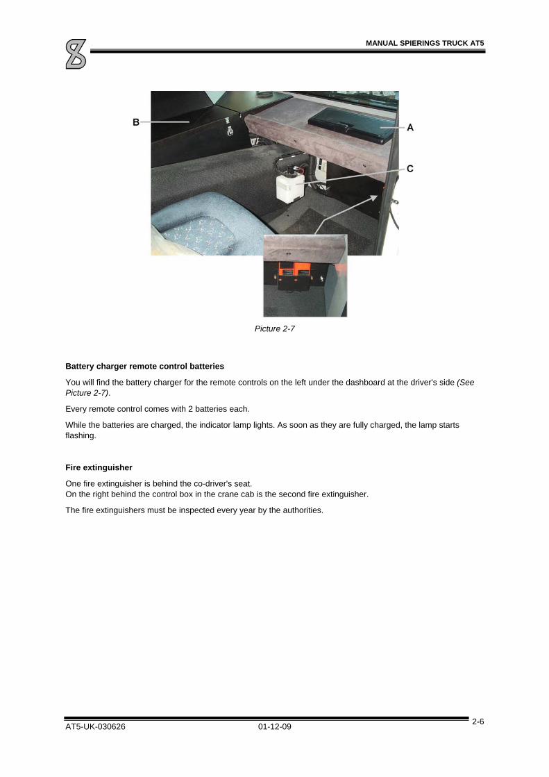
In the middle of the cab ceiling is a storage compartment. It has a lockable lid at the driver's side and at the side of the co-driver. There is another storage compartment at the co-driver's side in the dashboard (See Picture 2-7, A).
Sun blind
To prevent sunlight from blinding you, a sun blind is mounted above the windscreen for the driver and the co-driver. Pull down the blind with the joggle in the middle of the blind. The blind will remain in the desired position. Push the button on the side of the blind to roll it up.
Fuse box
The fuse box is at the co-driver's side in the centre console (See Picture 2-7, B). You will find the fuses listed in the enclosures.
Windscreen washer reservoir (See Picture 2-7, C)
Central lubricating system (optional)
The central lubricating system controls are on the centre panel at the co-driver's side. It can be opened by means of 2 clamps (See Picture 2-7, B).
MANUAL SPIERINGS TRUCK AT5
AT5-UK-030626 01-12-09 2-6
Picture 2-7
Battery charger remote control batteries
You will find the battery charger for the remote controls on the left under the dashboard at the driver's side (See Picture 2-7).
Every remote control comes with 2 batteries each.
While the batteries are charged, the indicator lamp lights. As soon as they are fully charged, the lamp starts flashing.
Fire extinguisher
One fire extinguisher is behind the co-driver's seat. On the right behind the control box in the crane cab is the second fire extinguisher.
The fire extinguishers must be inspected every year by the authorities.
MANUAL SPIERINGS TRUCK AT5
AT5-UK-030626 01-12-09 2-7
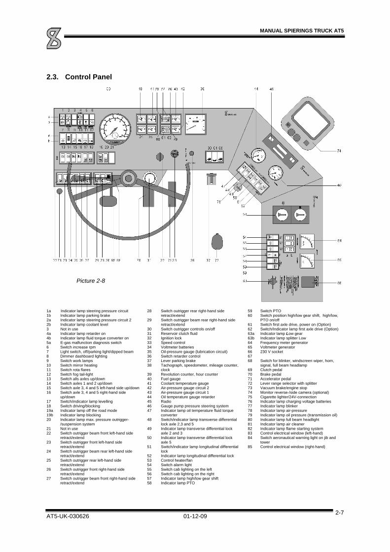
2.3. Control Panel
1a Indicator lamp steering pressure circuit 1b Indicator lamp parking brake 2a Indicator lamp steering pressure circuit 2 2b Indicator lamp coolant level 3 Not in use 4a Indicator lamp retarder on 4b Indicator lamp fluid torque converter on 5a E-gas malfunction diagnosis switch 6 Switch increase rpm 7 Light switch, off/parking light/dipped beam 8 Dimmer dashboard lighting 9 Switch work lamps 10 Switch mirror heating 11 Switch rota flares 12 Switch fog tail-light 13 Switch alls axles up/down 14 Switch axles 1 and 2 up/down 15 Switch axle 3, 4 and 5 left-hand side up/down 16 Switch axle 3, 4 and 5 right-hand side
up/down 17 Switch/indicator lamp levelling 18 Switch driving/blocking 19a Indicator lamp off the road mode 19b Indicator lamp blocking 20 Indicator lamp max. pressure outrigger-
/suspension system 21 Not in use 22 Switch outrigger beam front left-hand side
retract/extend 23 Switch outrigger front left-hand side
retract/extend 24 Switch outrigger beam rear left-hand side
retract/extend 25 Switch outrigger rear left-hand side
retract/extend 26 Switch outrigger front right-hand side
retract/extend 27 Switch outrigger beam front right-hand side
retract/extend
28 Switch outrigger rear right-hand side retract/extend
29 Switch outrigger beam rear right-hand side retract/extend
30 Switch outrigger controls on/off 31 Reservoir clutch fluid 32 Ignition lock 33 Speed control 34 Voltmeter batteries 35 Oil-pressure gauge (lubrication circuit) 36 Switch retarder control 37 Lever parking brake 38 Tachograph, speedometer, mileage counter,
clock 39 Revolution counter, hour counter 40 Fuel gauge 41 Coolant temperature gauge 42 Air-pressure gauge circuit 2 43 Air-pressure gauge circuit 1 44 Oil temperature gauge retarder 45 Radio 46 Gauge pump pressure steering system 47 Indicator lamp oil temperature fluid torque
converter 48 Switch/indicator lamp transverse differential
lock axle 2,3 and 5 49 Indicator lamp transverse differential lock
axle 2 and 3 50 Indicator lamp transverse differential lock
axle 5 51 Switch/indicator lamp longitudinal differential
lock 52 Indicator lamp longitudinal differential lock 53 Control heater/fan 54 Switch alarm light 55 Switch cab lighting on the left 56 Switch cab lighting on the right 57 Indicator lamp high/low gear shift 58 Indicator lamp PTO
59 Switch PTO 60 Switch position high/low gear shift, high/low,
PTO on/off 61 Switch first axle drive, power on (Option) 62 Switch/Indicator lamp first axle drive (Option) 63a Indicator lamp Low gear 63b Indicator lamp splitter Low 64 Frequency meter generator 65 Voltmeter generator 66 230 V socket 67 68 Switch for blinker, windscreen wiper, horn,
signal, full beam headlamp 69 Clutch pedal 70 Brake pedal 71 Accelerator pedal 72 Lever range selector with splitter 73 Vacuum brake/engine stop 74 Monitor reverse-/side camera (optional) 75 Cigarette lighter/24V-connection 76 Indicator lamp charging voltage batteries 77 Indicator lamp blinker 78 Indicator lamp air-pressure 79 Indicator lamp oil pressure (transmission oil) 80 Indicator lamp full beam headlight 81 Indicator lamp air cleaner 82 Indicator lamp flame starting system 83 Control electrical window (left-hand) 84 Switch aeronautical warning light on jib and
tower 85 Control electrical window (right-hand)
Picture 2-8

MANUAL SPIERINGS TRUCK AT5
AT5-UK-030626 01-12-09 2-8
1a. Indicator lamp steering pressure circuit 1
This Lamp lights up as soon as the oil pressure in steering circuit 1 is too low. Have the malfunction repaired as soon as possible. If this lamp lights together with lamp 2a: STOP IMMEDIATELY!
1b. Indicator lamp parking brake
As long as the parking brake is engaged, this lamp is on (when starting the engine the parking brake remains engaged as long as the air-pressure is below 5.5 bar).
2a. Indicator lamp steering pressure circuit 2
This lamp lights up as soon as the oil pressure in steering circuit 2 is too low. Have the malfunction repaired as soon as possible. If this lamp lights together with lamp 1a: STOP IMMEDIATELY! When the vehicle stands still, this lamp will light.
2b. Indicator lamp coolant level
This lamp lights up as soon as the coolant level is too low. Replenish coolant.
4a. Indicator lamp retarder
This lamp lights when the retarder is switched on.
4b. Indicator lamp fluid torque converter running
Refer to “Driving the Spierings Crane”
5a. E-gas diagnosis lamp/switch
This lamp starts flashing, when a error occurs.
To reset the system:
1. Turn off the engine and ignition
2. Push this button and turn on the ignition.
3. Wait for approx. 5 seconds and then release the button.
If the error is still active, the indicator lamp gives a flashing code. By means of the flashing code the nature of the malfunction can be determined. The amount of long flashes is the tens and the short flashes the single numbers. (if - is a long flash and . a short flash, ---... means error 23)
6. Switch increase rpm
By pressing this switch, you switch on the rpm-control.
Use this switch only when the vehicle stands still !!

MANUAL SPIERINGS TRUCK AT5
AT5-UK-030626 01-12-09 2-9
7. Light switch
By pressing this switch halfway, the parking lights are switched on. By pressing the switch all the way, the dipped beams are switched on.
8. Dimmer dashboard lighting
When switching on the vehicle lighting also the dashboard lighting goes on. With this dimmer you can change the dashboard lighting intensity.
9. Work Lamps
At the rear of the cab and truck are 2 work lamps each. With this switch the 4 work lamps are switched on and off.
10. Mirror heating
With this switch the mirror heating in the left en right wing mirror is switched on and off.
11. Rotaflare
With this switch the rota flares can be switched on and off.
12. Fog tail-light
With this switch the fog tail-light on the cab can be switched on and off.
Axle Height Adjustment
13. Switch for all axles up/down
ALL
AXLES
With this switch the cylinders of all axles are moved in and out simultaneously (e.g. when supporting the crane on outriggers).
14. Switch axles 1 and 2 up/down
AXLES 1-2
With this switch the cylinders of axles one and two can be moved in and out.

MANUAL SPIERINGS TRUCK AT5
AT5-UK-030626 01-12-09 2-10
15. Switch axle 3 left-hand side up/down
LEFT 3-4(-5)
With this switch the cylinders on the left side of the third, fourth and fifth axle can be moved in and out.
16. Switch axle 3 right-hand side up/down
RIGHT 3-4(-5)
With this switch the cylinders on the right side of the third, fourth and fifth axle can be moved in and out.
17. Switch/indicator lamp levelling
18. Switch/indicator lamp driving/blocking.
19a Indicator lamp off the road mode
19b Indicator lamp blocking
20. Indicator lamp max. pressure outrigger-/suspension system
This lamp goes on and a buzzer sounds at the rear outriggers as soon as the pressure in the outrigger/suspension system becomes too high. This may happen when the outriggers, the axles or the outrigger beams are fully in or out, or because there is an obstacle in the way when extending the outrigger beams. During leveling operation and when moving the axles up or down, this light could also go on. This does not present a problem.
If there’s no action of the outrigger-/suspension system, the lighting of this lamp means, that an error is occurred.
Outrigger Operation
(on the dashboard from left to right)
22. Switch outrigger beam front left-hand side retract/extend

MANUAL SPIERINGS TRUCK AT5
AT5-UK-030626 01-12-09 2-11
23. Switch outrigger front left-hand side retract/extend
24. Switch outrigger beam rear left-hand side retract/extend
25. Switch outrigger rear left-hand side retract/extend
26. Switch outrigger front right-hand side retract/extend
27. Switch outrigger beam front right-hand side retract/extend
28. Switch outrigger rear right-hand side retract/extend
29. Switch outrigger beam rear right-hand side retract/extend
30. Switch outrigger controls on/offSwitch off the outrigger controls when the outriggers are not operated or when the crane is rigged up/rigged down or in operation. The remote control is also de-activated. Failing to switch off the controls means the crane can not be set to the full hoisting program (full support base).
32. Ignition lock By turning the key to the right, three positions are possible, from left to right: 0 = ignition off 1 = ignition on 2 = flame start system (push the key before turning) 3 = starting
33. Rpm/speed control. With the speed control you can keep your current speed constant without using the accelerator pedal. The speed control doesn’t work at a speed under 30 km/h.
Set : Switch on and adjusting the speed control. If you are at the desired speed, move the lever to “set”. The speed control will hold on to this speed.
If the speed control is already switched on, the speed will increase by keeping the lever to “set”. If the speed control is switched on, you still can accelerate by using the accelerator pedal.
When the switch “increased rpm” is switched on, you can adjust the rpm of the engine with this lever.

MANUAL SPIERINGS TRUCK AT5
AT5-UK-030626 01-12-09 2-12
By moving the lever to set you can decrease the speed. Keep the lever down until you reach the desired speed.
Memo: When you brake or press the clutch, the speed control will switch off. By moving the lever to “memo”, the speed control will switch on again. It will adjust the speed back to the last saved speed (if speed >30 km/h). The shifted gear has to be the same as the last time you set the speed control.
The memory will reset when you shut down the engine.
Off: You can switch off the speed control by moving the lever to “off”. The speed control will also switch off by braking, pressing the clutch and in case of an accident.
Tip-up,Tip-down:
When you move the lever briefly to “set” or “set”, you will increase or decrease the speed with one km/h. The difference between the current speed and the new adjusted speed can not be more than 5 km/h.
34. Voltmeter batteries
On this meter you can read the battery condition. The meter must be in the middle (approx. 24 Volt)
35. Oil-pressure gauge lubrication circuit
When starting this gauge will read approx. 5 bar. As soon as the oil is warm approx. 3 bar.
36. Retarder (Optional) Refer to “Slowing down using the retarder”
37. Lever parking brake By pulling this lever. backwards the parking brake is engaged. Pulling out the knob and pushing the lever forwards will release the parking brake. To release the parking brake, the pressure must be at least 5.5 bar.
38. Speedometer/tachograph The truck is equipped with a VDO tachograph. On this device you can read the driving speed and the number of kilometres driven. The tachograph also contains a clock (1). This clock drives a diagram disc. On this disc the activities of the driver are written by means of scribers. The disc can be replaced by opening slot 2 (See Picture 2-9). Never leave a disc in the tachograph for longer than 24 hrs (else it would overwrite itself). In case there is no disc in the tachograph, indicator lamp 3 will light up.
By means of switches 4 and 5 the drivers' activities can be shown. Indicator lamp 3 goes on as soon as the driving speed exceeds 80 km/h. When at a certain speed button 6 is pressed, exceeding this speed will light up the indicator lamp. However, when the ignition is switched off, the indicator lamp will be set to 80 km/h.
The clock may be set to the correct time by operating wheel A.
For more details on how to use the tachograph we refer to the tachograph manual (in the glove compartment).

MANUAL SPIERINGS TRUCK AT5
AT5-UK-030626 01-12-09 2-13
Note: registration of crane operation by the tachograph is not laid down by law.
Picture 2-9
39. Revolution counter On this counter you can read the diesel engine rpm. The revolution counter has a built-in hour counter. On this counter you can read the number of operating hours of the diesel engine.
40. Fuel gauge
The gauge only functions when the ignition is switched on.
41. Coolant temperature gauge
On this gauge you can read the coolant temperature. In the diesel engine safety system an overheating sensor is built-in. As soon as the temperature exceeds 110 °C, it activates the horn. The engine must be switched off immediately.
42. Air-pressure gauge circuit 2 It indicates the air-pressure in brake circuit 2. When the pressure is below 5.5 bar, indicator lamp 78 will light up. The crane must not be driven.
43. Air-pressure gauge circuit 1 It indicates the air-pressure in brake circuit 1. When the pressure is below 5.5 bar, indicator lamp 78 will light up. The crane must not be driven.
44. Oil temperature retarder (optional) During normal use the temperature does not exceed 130°C. If the indicator enters the red zone, you have to gear down or set the retarder at a lower value. If this does not help, the retarder must be switched off. In the red zone the oil temperature is too high and at 145°C you will hear an acoustic warning signal.
46. Oil-pressure gauge steering circuit 2 / suspension system / outriggering / first axle drive
On this gauge you can read the pressure in the hydraulic system of steering circuit 2, the suspension system and when supporting the crane on outriggers (and the pressure of the first axle drive).

MANUAL SPIERINGS TRUCK AT5
AT5-UK-030626 01-12-09 2-14
48. Switch/indicator lamp transverse differential lock
51. Switch/indicator longitudinal differential lock
53. Heating
With this selector switch the heating fan can be set at 3 speeds and switched off.
By turning this rotary knob the heat supply can be continuously regulated.
55/56 Cab lighting
The driver and co-driver can operate the cab lighting by operating the switch (no. 55 + 56) on the dashboard. The lighting will also go on when opening the door. We advise you not to switch on the cab lighting when driving in the dark, to prevent annoying reflections in the windscreen.
59. Selector switch PTO
With this switch the PTO is switched on. While the PTO is switched on indicator lamp 58 is on. The PTO drives a generator, which supplies power for crane operation. When the upper frame has its own diesel engine, this switch has no function.
Caution!
While the PTO is switched on, driving the crane is forbidden!
60. Selector switch gear shift high/low, PTO on/off With this switch the off-the-road (Low) or on-the-road (High) gear can be selected. This is indicated by indicator lamp 57. With this switch and switch 59 the PTO is switched on. Indicator lamp 58 indicates when the PTO is switched on.
Caution!
Transfer case gear shift high/low may only be operated when the vehicle stands still!
64. Frequency meter generator (not in case of a diesel engine on the upper frame) It indicates the frequency in Hertz, supplied by the generator and must be between 52.5 and 53.5Hz.
65. Voltmeter generator (not in case of a diesel engine on the upper frame) It indicates the current supplied voltage by the generator. It should be approx. 400V.

MANUAL SPIERINGS TRUCK AT5
AT5-UK-030626 01-12-09 2-15
67. Vacuum brake/engine stop
68. Steering column switch (See Picture 2-10)
D
DF
JG
E H
Picture 2-10
D With this switch the direction indicator is controlled. E Pushing the switch forward switches on the full beam headlight. F Pulling the switch backwards you can give light signals (F). G Pressing the switch tip towards the steering wheel activates the horn (G). H Pressing the entire outer part of the lever towards the steering wheel activates the windscreen
washer (H). J Turning the outer part activates the windscreen wipers. The ---- position is intermittent.
Position 1 is normal and position 2 high speed wiping.
76. Warning lamp charging voltage batteries
If the charging voltage of the batteries is too low, this indicator lamp will go on.
78. Warning lamp air-pressure
If the air-pressure in brake circuit 1 or 2 is below 5.5 bar, this indicator lamp will go on. The crane must not be driven. If this lamp is on after starting the engine, leave the engine running at idling speed until the air-pressure is 5.5 bar. The lamp will go out.
82. Indicator lamp flame starting system
This lamp goes on when pre-heating the engine.
83/85. Electrically operated door windows left/right
The door windows can be opened and closed with these switches. At the co-driver's side there is a switch on the dashboard. All these switches only function with turned on ignition and closed door.

MANUAL SPIERINGS TRUCK AT5
AT5-UK-030626 01-12-09 2-16
84. Aeronautical warning light on tower head and jib head (optional)
With this switch the aeronautical warning light on the tower head and jib head can be switched on and off.
2.4. Driving the Spierings crane
The driver is expected to have a driving license for driving a heavy truck and have sufficient technical knowledge. While driving and manoeuvring the crane, the driver must be aware of the crane's unusual form, measurements and steering characteristics;
Crane parts sticking out at the front and rear
Its height of four metres: pay attention to low passage ways and low breaches
Its width of 3 metres: on narrow roads and passage ways it can form an obstruction for other traffic
Steering conduct: thanks to the opposite steered rear wheels, the crane has a small turning circle. Hereby the rear end may swing out a bit.
Caution!
The rear side of the crane swings round by taking corners.
Do not overload the engine during the run in period. (1500 km or 30 hours) Shift back the gear in an early time. A relatively high rpm is less harmful then overloading with low rpm.
2.4.1. Starting
Before starting the engine, the transmission must be put in neutral and the parking brake must be engaged.
Because the engine has a direct diesel injection it needs no pre-heating over 0° C. You can start the engine by simply turning the ignition key to position 3. If the temperature is below freezing point, the engine must be pre-heated. Pre-heating times are:
30 seconds at temperatures between 0° C and -10° C
90 seconds at temperatures below -10° C
While pre-heating the indicator lamp is on.
When 9the engine is running the indicator lamps for oil pressure and battery charging must go out. Only when the oil pressure lamp is out, the engine speed may be increased. When the engine runs too hot or the engine oil pressure is too low, the horn will sound. If the horn keeps sounding, the engine must be switched off immediately. The lamp for steering circuit 2 will remain on while the vehicle stands still. It will go out the moment the vehicle starts moving.
After a cold start you must drive in low gear and at low speed until the coolant temperature reaches 50o C.
During running in (1500 km or 30 operating hours) we advise you not to load the engine to its maximum. Gear down in time. A relatively high rpm causes less damage than overload at low speed.

MANUAL SPIERINGS TRUCK AT5
AT5-UK-030626 01-12-09 2-17
2.4.2. Driving off
In order to drive off, the air-pressure in the system must be at least 5.5 bar. Below this pressure the clutch can not be pressed and the parking brake can not be released when operated.
The fluid torque converter is used to drive off. Normally, driving off is possible in 3rd or 4th gear. Drive off in first or second 1st 2nd in terrain or in the hills. Avoid driving off in high gear. This will cause high fuel usage and development of heat in the converter.
Drive off as follows;
Start the engine on the parking.
Engage the clutch and shift the right gear.
Unclutch and let release the parking brake.
After releasing the parking brake, the vehicle will slowly drive off. By stepping on the gas, the vehicle will accelerate without shaking. Before releasing the parking brake, open the throttle some more on a hill to avoid rolling away.
A yellow lamp on the dashboard (4b) indicates that the converter is working. After reaching a certain number of revolutions, the coupling is connected. The converter is then switched off. The indicator lamp goes out and you may shift gear. After shifting gear the indicator lamp will remain off.
The connection of the coupling remains. Only when the number of revolutions is less than 40% of the maximum number of revolutions, the connection is undone.
When driving under 40% of the maximum number of revolutions (yellow lamp lights) for a longer time, keep an eye on the oil-temperature gauge of the gear box. The oil-temperature may not be more than 130°C. When the temperature gets to high, shift back to a lower gear to make more revolutions.
If shifting down doesn’t work, stop the vehicle immediately. After stopping, shift gear to neutral and open the throttle a bit. After a few minutes, the oil-temperature has to be normal again. If the temperature remains high, the cooler is broken or the oil level in the gearbox is too low.
2.4.3. Change gear
The gearbox has 8 synchronized gears; they are divided in a low range (1st - 4th) and a high range (5th - 8th). To shift between the two ranges, the shift lever must be in neutral position and be pushed to the right through a slight resistance. Subsequently the high range gears can be engaged. To return to the low range, the gear shift lever must be put in neutral and be pushed to the left.
Refer to the diagram in the picture alongside.
Every gear can be shifted in an intermediate gear; the so-called splitter. Shifting to a lower or higher splitter or v.v. is done by operating the splitter switch. Then press the clutch and release it again.
Picture 2-11

MANUAL SPIERINGS TRUCK AT5
AT5-UK-030626 01-12-09 2-18
Caution!
While gearing down from high to low range, the driving speed must be below 30 km/h!
Reverse gear is not synchronized, it may only be engaged when the vehicle stands still and the engine runs at idling speed. Also in reverse you can use the high and low splitter.
2.4.4. Stopping
The driver can stop the carrier in every gear without engaging the clutch. For a short stop, you can leave the clutch unengaged. Although, you’ll have to brake, otherwise the carrier will drive off again.
To shift gears you always have to engage the clutch.
2.4.5. Turning off the engine
The engine can be switched off by pushing the engine stop. Under the front bumper a chain is mounted. The engine also can be stopped by pulling the chain.
If the engine has run for a longer period of time, we advise you to leave the engine running at idling speed for a few minutes before switching it off, to prevent the coolant and turbo from overheating.
Below the deck of the left-hand front wheel is a chain. This chain can be used to turn off the engine when the engine stop fails.
2.5. Driving off the road
2.5.1. Off the road gear shift High/Low transfer case
When driving off the road or at low speed is required (e.g. driving with erected tower) you can put the gear shift high/low in low speed (L). (Main gear in the neutral position)
Caution!
The gear shift high/low may only be operated when the vehicle stands still!
The position of the gear shift high/low is indicated by indicator lamps on the control panel (H or L). Shifting to another position takes about 5 seconds.

MANUAL SPIERINGS TRUCK AT5
AT5-UK-030626 01-12-09 2-19
2.5.2. Longitudinal differential lock
When there is insufficient traction while driving off the road, the longitudinal differentials can be locked with button "longitudinal differential lock".
Engagement of the longitudinal differential lock is indicated by the indicator lamp next to the button.
Caution!
The longitudinal differential lock may only be engaged/released when the vehicle stands still!
Driving with engaged longitudinal differential lock is only allowed when the vehicle moves in a straight line!
After releasing the longitudinal differential lock, make sure the indicator lamps are out! If this is not the case, slowly zigzag a little when driving off; this should make the lamps go out.
2.5.3. Transverse differential lock
If after engaging the longitudinal differential lock there is still too little traction, also the differentials in the axles may be locked.
Do this by operating the button "transverse differential lock". To keep the transverse differential lock engaged, the button must be pressed. As soon as the button is released, it will snap back and release the transverse differential lock.
Before driving on a paved road, it is required to release the transverse differential lock.
Locking of the axles is indicated by indicator lamps 49 and 50.
Caution!
The transverse differential lock may only be engaged/released provided the vehicle stands still and the longitudinal differential lock is engaged (indicator lamp 52 is on)
Driving with engaged longitudinal differential lock may only when the vehicle moves in a straight line on loose ground!
After releasing the transverse differential lock make sure the indicator lamps are out!
2.5.4. Hydraulic driven axle 1
The first axle can be driven by a separate hydraulic drive. This hydraulic drive is for use in terrain and can only be used at low speed.
Before switching on the front wheel drive you have to shift the gear box in lower splitter and the
transfer case in low gear. After doing so, you can switch on the front wheel drive with the switch on
the dashboard. As soon as the drive is switched on, it starts to work.
When the oil-pressure is higher, the power-output will be bigger. You can read the pressure on the gauge in the dashboard (46). By driving with a higher number of revolutions, you can increase the pressure.

MANUAL SPIERINGS TRUCK AT5
AT5-UK-030626 01-12-09 2-20
2.6. Braking system
All axles are equipped with drum brakes. The crane is equipped with three braking systems:
Operating brake
Parking brake (of axle 2, 3 and 4)
Vacuum brake/engine stop
The crane can also be provided with an optional retarder.
2.6.1. Operating brake
The operating brake is operated with the brake pedal and works fully pneumatically. The air pressure is indicated on the dashboard by two air-pressure gauges. If the pressure is below 5.5 bar, it is indicated by the indicator lamp on the dashboard. The crane must not be driven.
2.6.2. Parking brake
The parking brake is engaged when the parking brake lever is moved backwards. This bleeds the spring loaded brake boosters and engages the brake. When pulled fully backwards, the lever is locked and the parking brake remains engaged. Pulling out the knob on the lever and pushing the lever forwards will release the parking brake.
If the air pressure for the operating brake is too low, the parking brake is used to slow down the moving vehicle. Move the parking brake lever gradually backwards. Once operated the parking brake can not be released until the air pressure is back to normal. (Also refer to: Towing the crane)
2.6.3. Vacuum brake/engine stop
The vacuum brake works by closing the fuel supply. Also the exhaust is closed by means of a valve. The vacuum brake control is to the left of the clutch pedal on the truck cab floor. While this foot switch is pressed the vacuum brake is active. The vacuum brake is used to slow down through the engine (e.g. when travelling down-hill) and to switch of the engine.
Caution!
While the vacuum brake is in use, the engine speed may not drop below 2500 rpm!
Do not use the vacuum brake when the gear is in neutral while you’re driving. The engine will cut out!
2.6.4. Slowing down using the retarder (optional)
For slowing down when driving at high speed or on long stretches down-hill, the use of the retarder is profitable. Sparing the operating brake, the operating brake is fully available when it is really needed. The retarder is activated with the control lever on the control panel. This lever has six positions to control the braking force. The indicator lamp on the control panel indicates if the retarder is activated.
Using the accelerator pedal is not possible when the retarder is activated
MANUAL SPIERINGS TRUCK AT5
AT5-UK-030626 01-12-09 2-21
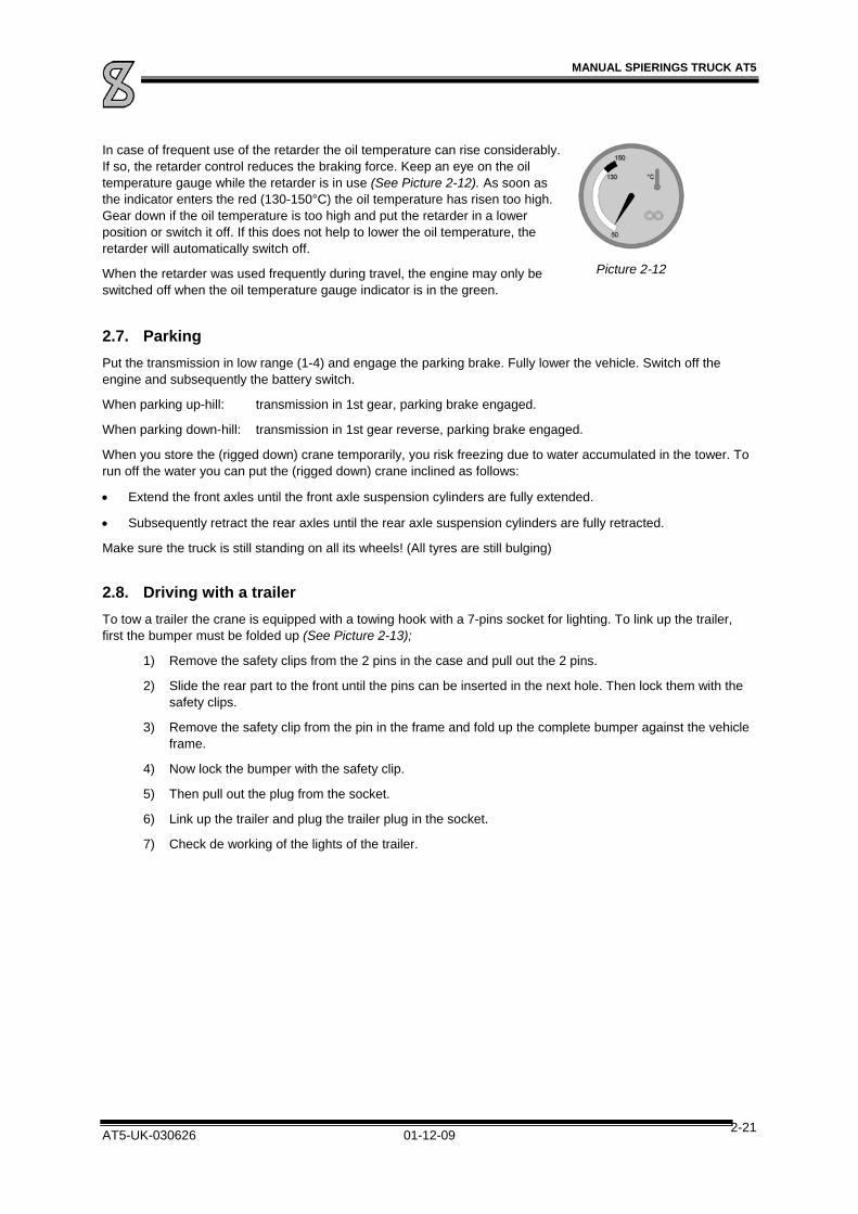
In case of frequent use of the retarder the oil temperature can rise considerably. If so, the retarder control reduces the braking force. Keep an eye on the oil temperature gauge while the retarder is in use (See Picture 2-12). As soon as the indicator enters the red (130-150°C) the oil temperature has risen too high. Gear down if the oil temperature is too high and put the retarder in a lower position or switch it off. If this does not help to lower the oil temperature, the retarder will automatically switch off.
When the retarder was used frequently during travel, the engine may only be switched off when the oil temperature gauge indicator is in the green.
Picture 2-12
2.7. Parking
Put the transmission in low range (1-4) and engage the parking brake. Fully lower the vehicle. Switch off the engine and subsequently the battery switch.
When parking up-hill: transmission in 1st gear, parking brake engaged.
When parking down-hill: transmission in 1st gear reverse, parking brake engaged.
When you store the (rigged down) crane temporarily, you risk freezing due to water accumulated in the tower. To run off the water you can put the (rigged down) crane inclined as follows:
Extend the front axles until the front axle suspension cylinders are fully extended.
Subsequently retract the rear axles until the rear axle suspension cylinders are fully retracted.
Make sure the truck is still standing on all its wheels! (All tyres are still bulging)
2.8. Driving with a trailer
To tow a trailer the crane is equipped with a towing hook with a 7-pins socket for lighting. To link up the trailer, first the bumper must be folded up (See Picture 2-13);
1) Remove the safety clips from the 2 pins in the case and pull out the 2 pins.
2) Slide the rear part to the front until the pins can be inserted in the next hole. Then lock them with the safety clips.
3) Remove the safety clip from the pin in the frame and fold up the complete bumper against the vehicle frame.
4) Now lock the bumper with the safety clip.
5) Then pull out the plug from the socket.
6) Link up the trailer and plug the trailer plug in the socket.
7) Check de working of the lights of the trailer.
MANUAL SPIERINGS TRUCK AT5
AT5-UK-030626 01-12-09 2-22
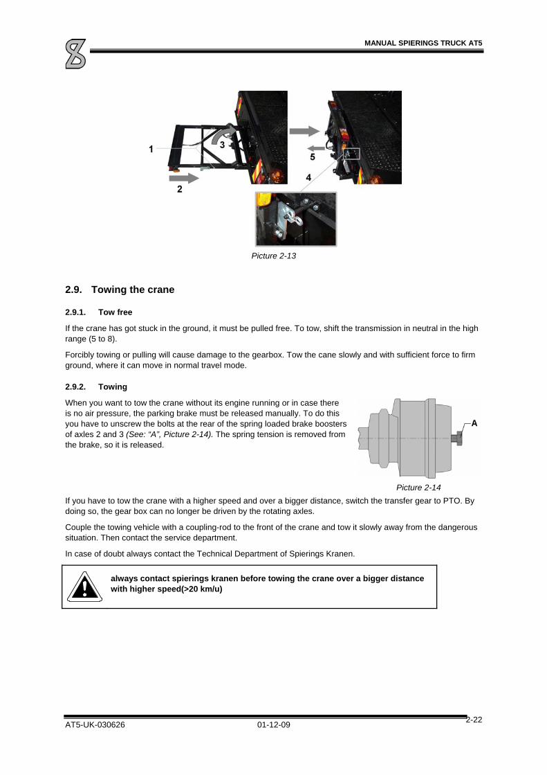
Picture 2-13
2.9. Towing the crane
2.9.1. Tow free
If the crane has got stuck in the ground, it must be pulled free. To tow, shift the transmission in neutral in the high range (5 to 8).
Forcibly towing or pulling will cause damage to the gearbox. Tow the cane slowly and with sufficient force to firm ground, where it can move in normal travel mode.
2.9.2. Towing
When you want to tow the crane without its engine running or in case there is no air pressure, the parking brake must be released manually. To do this you have to unscrew the bolts at the rear of the spring loaded brake boosters of axles 2 and 3 (See: “A”, Picture 2-14). The spring tension is removed from the brake, so it is released.
Picture 2-14
If you have to tow the crane with a higher speed and over a bigger distance, switch the transfer gear to PTO. By doing so, the gear box can no longer be driven by the rotating axles.
Couple the towing vehicle with a coupling-rod to the front of the crane and tow it slowly away from the dangerous situation. Then contact the service department.
In case of doubt always contact the Technical Department of Spierings Kranen.
always contact spierings kranen before towing the crane over a bigger distance with higher speed(>20 km/u)
MANUAL SPIERINGS TRUCK AT5
AT5-UK-030626 01-12-09 2-23
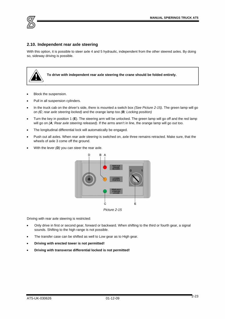
2.10. Independent rear axle steering
With this option, it is possible to steer axle 4 and 5 hydraulic, independent from the other steered axles. By doing so, sideway driving is possible.
To drive with independent rear axle steering the crane should be folded entirely.
Block the suspension.
Pull in all suspension cylinders.
In the truck cab on the driver’s side, there is mounted a switch box (See Picture 2-15). The green lamp will go on (C; rear axle steering locked) and the orange lamp too (B; Locking position)
Turn the key in position 1 (E). The steering arm will be unlocked. The green lamp will go off and the red lamp will go on (A; Rear axle steering released). If the arms aren’t in line, the orange lamp will go out too.
The longitudinal differential lock will automatically be engaged.
Push out all axles. When rear axle steering is switched on, axle three remains retracted. Make sure, that the wheels of axle 3 come off the ground.
With the lever (D) you can steer the rear axle.
Picture 2-15
Driving with rear axle steering is restricted:
Only drive in first or second gear, forward or backward. When shifting to the third or fourth gear, a signal sounds. Shifting to the high range is not possible.
The transfer case can be shifted as well to Low gear as to High gear.
Driving with erected tower is not permitted!
Driving with transverse differential locked is not permitted!
MANUAL SPIERINGS TRUCK AT5
AT5-UK-030626 01-12-09 2-24
To switch back to normal driving situation, you have o proceed as follows:
Retract the cylinders until axle 3 (almost) reaches the ground.
Steer the rear axle until the steering arm are in line (orange lamp will go on).
Turn the key to position 0. De steering arms of axle 4 will be locked. The red lamp goes out and the green will go on. The longitudinal differential lock will be disengaged. If the red lamp doesn’t go out, turn the steering wheel carefully a bit to the left and right until the red lamp goes out.
The suspension will return in driving position and all the gears can be shifted again.
After levelling, you can drive normal again.
2.11. Driving with erected tower
Refer to crane manual.

MANUAL SPIERINGS TRUCK AT5
AT5-UK-030626 01-12-09 2-25
2.12. Axle height adjustment
The carriage axles are connected to the chassis by means of hydraulic cylinders. Each cylinder is provided with an accumulator, so that the axles can compress.
The suspension system can be controlled from the truck cab (See Picture 2-16). This system enables you to adjust the axle height according to your needs. The suspension can also be blocked; this is relevant when supporting the crane on outriggers and when driving with an erected tower.
The suspension system operation is explained below.
Picture 2-16 O. switch cylinders of all axles; in / out
P. switch cylinders axles 1 and 2; in / out
Q. switch cylinders left-hand side; left wheel axles 3, 4 and 5 in / out
R. switch cylinders right-hand side; right wheel axle 3, 4 and 5 in / out
In this way, the crane set-up can be levelled on sloping grounds.
As soon as the end position is reached, a buzzer will sound and indicator lamp 20 on the control panel will go on.
“Levelling” (S)
During levelling, the axle suspension is automatically adjusted in travelling mode. This is useful when the axle height had become unsettled due to e.g. outrigger operation or lengthy standstill. After using the crane it should always be levelled!
The crane must be levelled on a horizontally level base and the levelling is finished when there is no more movement in the vehicle and the indicator lamp in the levelling switch is on. Now reset the switch.
Levelling can only be done when the tower is resting on the truck.
Switch T must be on “driving” for levelling operation!
“Driving” (T)
In this switch position the suspension is activated. The switch must be in this position while driving on the road.
Before driving off, you have to level first.

MANUAL SPIERINGS TRUCK AT5
AT5-UK-030626 01-12-09 2-26
“Blocking” (T)
In this mode the axles can not compress, enabling a stable travel. In blocking mode the indicator lamp on the switch for blocking/driving is on. In this mode the axles can be moved up or down separately by means of 4 switches. When the system is blocked, indicator lamp 19b is on.
“Off-the-road mode”
To shift the crane in off the road mode, you have to proceed as follows:
Block the axles.
Move the cylinders of all axles out. The cylinders will not go out all the way, so that some room to move remains.
Release the suspension to re-activate the suspension.

MANUAL SPIERINGS TRUCK AT5
AT5-UK-030626 01-12-09 3-1
3. Maintenance
3.1. General
In this part of the manual the crane maintenance is dealt with. After some safety rules, you will find the maintenance plan and the daily and weekly checks for the crane driver/operator.
Subsequently several truck systems and their specific maintenance work are described.
3.2. Safety
3.2.1. Engine
Do not run the engine in a closed or non-aired room. There is danger of suffocation!
3.2.2. Moving components
Stay on a safe distance from rotating and/or moving components!
3.2.3. Oils and coolant
Various kinds of oil and coolant can be harmful to your health when touched. Avoid any physical contact with these substances! Do not remove the coolant tank filler cap while the engine is at operating temperature!
3.2.4. Welding
When welding on the truck or crane, the battery switch (against the battery box) must be switched off. Make sure welding spatter does not fall on hydraulic, pneumatic or electrical parts.
Carrying out modifications or welding on the crane is only allowed with specific permission of the manufacturer!

MANUAL SPIERINGS TRUCK AT5
AT5-UK-030626 01-12-09 3-2
3.2.5. Environment
In order to reduce environmental pollution to a minimum we advise you to comply with the following rules:
Do not pour used oils, hydraulic fluid or coolant in sewers or in the ground. Make sure all used fluids are separated and sent to the respective authorities for destruction or recycling.
See to proper and regular truck maintenance. A well maintained engine contributes to saving fuel and reduces polluting exhaust fumes.
3.2.6. Cleaning of components
While cleaning with a high-pressure cleaner the following rules must be complied with:
While cleaning the radiator/intercooler, make sure the cooler fins do not get damaged.
While cleaning the engine compartment, do not point the nozzle directly to electrical components like starter motor, dynamo, etc.
Make sure no water penetrates through the breathers of gearbox, transfer case and differentials.

MANUAL SPIERINGS TRUCK AT5
AT5-UK-030626 01-12-09 3-3
3.3. Maintenance plan truck AT5
The following maintenance plan is drawn up in order to optimally combine the maintenance work of various AT5 components.
In consultation with Spierings Kranen a different maintenance plan can be drawn up. You can also work with maintenance plans for the separate components.
You will find maintenance work for the DAF service intervals in the enclosed maintenance manual for the engine. On the 1st DAF engine inspection/maintenance the warranty form for the engine is filled out by the DAF-dealer.
Daily maintenance
Engine oil Check the level Coolant Check the level Tyres and rims Check for damage and sticking
objects. Check the tyre pressure (7.5 bar)
Lighting and Instruments Check the proper functioning Weekly maintenance
General Check for leaks (diesel-, hydraulic and engine oil, air, coolant)
Windscreen washer fluid Check the level Clutch fluid Check the level Air vessels Drain water Gearbox Check and clean breather V-belt Check tension Water separator fuel system Check for dirt and water
If needed drain water and dirt 1st Inspection/maintenance
DAF-engine 1st Service interval (after 350 hours) Entire truck Spierings' "400-hours" inspection: Change oil drive components Replace oil filter
Check/torque bolt connections Check components and hose
connections for leaks. 2-Monthly maintenance
and minor inspection
Gearbox and clutch Check air pressure hose connections.
Check and clean breather Check the gearbox oil level and
top up if necessary Bleed the clutch if necessary Check the clutch fluid level and
top up if necessary Transfer case Check connections and air
pressure hoses for leaks. Check and clean breather Check the oil level and top up if
necessary.
MANUAL SPIERINGS TRUCK AT5
AT5-UK-030626 01-12-09 3-4
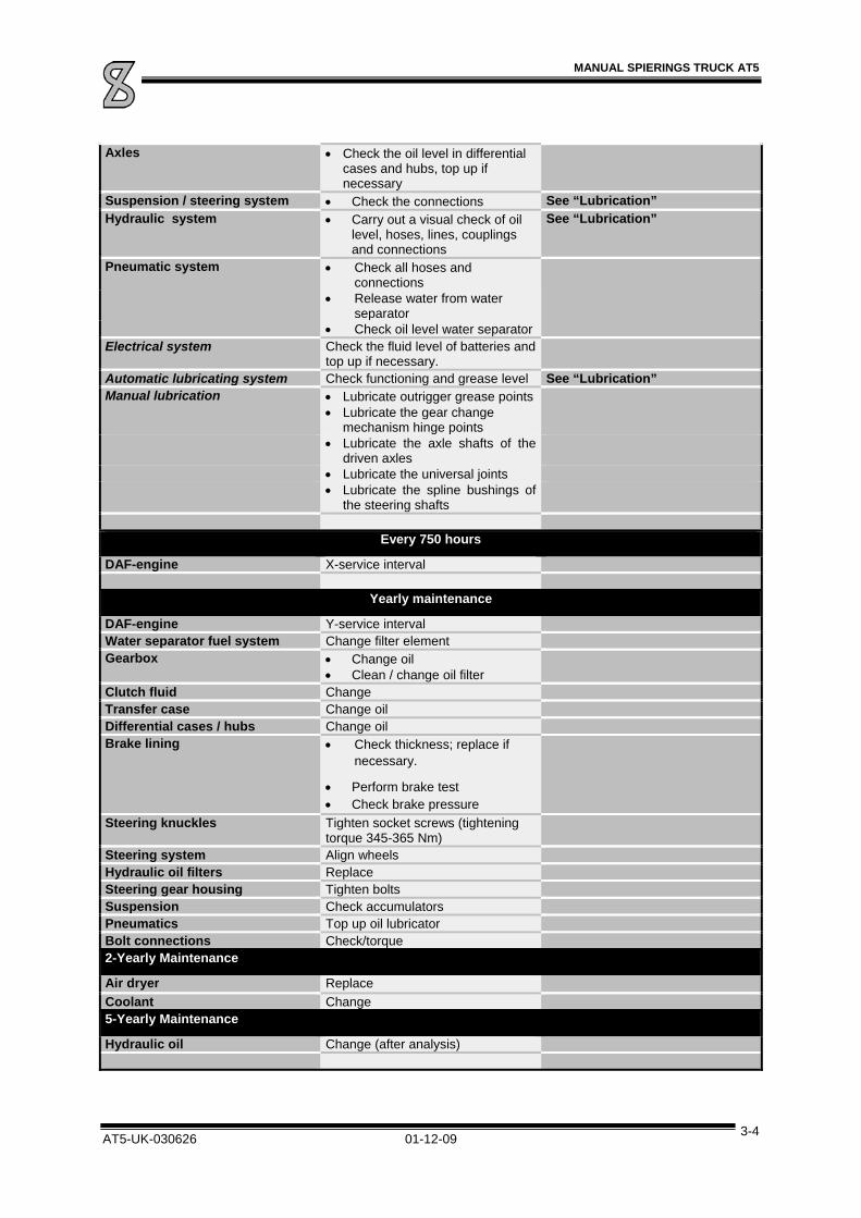
Axles Check the oil level in differential cases and hubs, top up if necessary
Suspension / steering system Check the connections See “Lubrication” Hydraulic system Carry out a visual check of oil
level, hoses, lines, couplings and connections
See “Lubrication”
Pneumatic system Check all hoses and connections
Release water from water separator
Check oil level water separator Electrical system Check the fluid level of batteries and
top up if necessary. Automatic lubricating system Check functioning and grease level See “Lubrication” Manual lubrication Lubricate outrigger grease points Lubricate the gear change
mechanism hinge points Lubricate the axle shafts of the
driven axles Lubricate the universal joints Lubricate the spline bushings of
the steering shafts
Every 750 hours
DAF-engine X-service interval
Yearly maintenance
DAF-engine Y-service interval Water separator fuel system Change filter element Gearbox Change oil
Clean / change oil filter Clutch fluid Change Transfer case Change oil Differential cases / hubs Change oil Brake lining Check thickness; replace if
necessary.
Perform brake test Check brake pressure
Steering knuckles Tighten socket screws (tightening torque 345-365 Nm)
Steering system Align wheels Hydraulic oil filters Replace Steering gear housing Tighten bolts Suspension Check accumulators Pneumatics Top up oil lubricator Bolt connections Check/torque 2-Yearly Maintenance
Air dryer Replace
Coolant Change 5-Yearly Maintenance
Hydraulic oil Change (after analysis)

MANUAL SPIERINGS TRUCK AT5
AT5-UK-030626 01-12-09 4-1
4. Periodic checks
4.1. Daily checks
4.1.1. Check engine oil level
To check the oil level you will find a dipstick (1) at the truck cab rear left-hand side. There is also a filler hole (with red cap) for topping up engine oil (2).
Make sure the crane stands on a horizontally flat base.
Pull out the dipstick (1).
Clean the dip stick with a non-fluff cloth.
Put the dipstick back in the holder.
Subsequently pull it out again and read off the level.
The oil level must be between the two marks on the dipstick.
If necessary, top up oil through the filler hole (2). Always use oil of the same brand and type (refer to “technical data”)
Picture 4-1
4.1.2. Check coolant level
In order to check the coolant level and topping it up, the tower must be tilted to approx. 1 metre above the truck cab.
In the middle behind the truck cab is a (blue) filler hole for the coolant. The fluid level must be half way the filler neck. If the coolant level is extremely low, the system must be checked for leaks.
Check the coolant level while the engine is cold. If you have to check when the engine is still hot (just after finishing work) turn the filler cap carefully against the stop to relief the pressure in the cooling system. Then press the filler cap down and turn it until you can remove it.
Picture 4-2

MANUAL SPIERINGS TRUCK AT5
AT5-UK-030626 01-12-09 4-2
Put the heater knob on “warm”.
Remove the (blue) cooling system filler cap.
Leave the engine running for some seconds.
Switch off the engine and check the fluid level and top up, if necessary, until the level is halfway the filler neck.
Topping up coolant in a warm engine must be done slowly while the engine is running, to prevent damage to the engine block.
Do not remove the coolant tank filler cap while the engine is at operating temperature!
The coolant must comply with the required specifications. (Refer to “TECHNICAL DATA”).
4.1.3. Tyres and rims
Check the tyres and rims for damage, and objects stuck in the surface.
Remove stuck objects from the surface.
Check the tyre pressure (when the tyres are cold, do not forget the spare tyre) and inflate if necessary.
4.1.4. Lighting and controls
Check the vehicle lighting (and possible trailer) and the proper functioning of the controls.
4.2. Weekly checks
4.2.1. Check for leaks (oil, air, coolant)
Check lines and connections for air leaks, fuel leaks, hydraulic oil leaks and lubricant leaks. In case the synthetic fuel line's condition is such that rubbing through is expected or already visible, it must be replaced.
4.2.2. Windscreen washer fluid level
The windscreen washer fluid tank is in the truck cab at the co-driver's side (refer to “Truck cab”). Check the fluid level in the tank and top up with water, to which you can add some cleaning fluid.
Add antifreeze to the water when the temperature outside is subzero.
4.2.3. Clutch fluid level
The reservoir for clutch fluid is at the right of the steering wheel in the truck cab.
Check clutch fluid level:
The reservoir for the clutch fluid is at the right side of the steering wheel in the dashboard (refer to “Control panel”). The fluid level should be between MAX and MIN. Check the fluid level in the reservoir and, if necessary, top up with clutch fluid according to the specifications in “TECHNICAL DATA”.
Caution!
Prevent spilling brake fluid on the synthetic dashboard. The synthetic material can easily be harmed by brake fluid, causing it to crack!
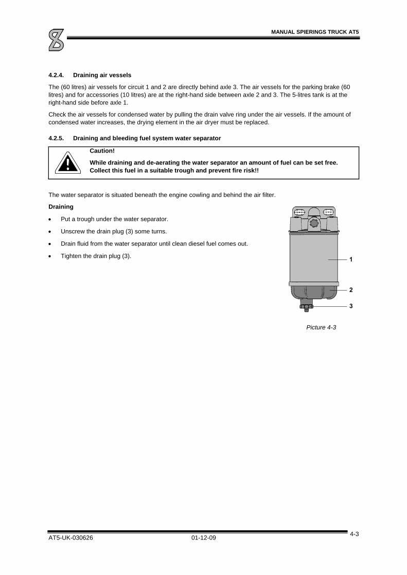
MANUAL SPIERINGS TRUCK AT5
AT5-UK-030626 01-12-09 4-3
4.2.4. Draining air vessels
The (60 litres) air vessels for circuit 1 and 2 are directly behind axle 3. The air vessels for the parking brake (60 litres) and for accessories (10 litres) are at the right-hand side between axle 2 and 3. The 5-litres tank is at the right-hand side before axle 1.
Check the air vessels for condensed water by pulling the drain valve ring under the air vessels. If the amount of condensed water increases, the drying element in the air dryer must be replaced.
4.2.5. Draining and bleeding fuel system water separator
Caution!
While draining and de-aerating the water separator an amount of fuel can be set free. Collect this fuel in a suitable trough and prevent fire risk!!
The water separator is situated beneath the engine cowling and behind the air filter.
Draining
Put a trough under the water separator.
Unscrew the drain plug (3) some turns.
Drain fluid from the water separator until clean diesel fuel comes out.
Tighten the drain plug (3).
Picture 4-3


MANUAL SPIERINGS TRUCK AT5
AT5-UK-030626 01-12-09 5-1
5. Lubrication
To grease the grease points the carriage is fitted with a central lubricating system. A number of grease points have to be greased manually. (See “Manual lubrication”)
5.1. Central lubricating system
This system is controlled by a switch clock on which the grease time in relation to the operating time can be set (See Picture 5-1).
Check the grease level in the reservoir. It must be above MIN (1). If not, fill it, e.g. by means of a grease gun, through the respective grease nipple (2). Use grease according to the specification in ”TECHNICAL DATA”.
The grease pump (with reservoir) for the automatic lubricating system is at the top of the truck under the engine cowling (See Picture 5-2). In order to check and fill it, the top cover plate on the truck must be removed.
Picture 5-2
Check the functioning of the central lubricating system regularly (every 2 months)!
The switch clock must be set in such a way that 24 hours of operation are followed by 15 minutes greasing. To do this one clock slide must be extended. When the switch is set to 'auto', the switch clock starts functioning. If extra greasing is needed, you can operate the grease pump by putting the switch on I. For automatic greasing the switch must be in position “A”. If the PTO is switched running and if the engine is off, the central lubricating system is not working.
The central lubricating system clock is on the centre panel at the co-driver's side. It can be opened by means of 2 clamps. (Refer to “Truck cab”).
Picture 5-1

MANUAL SPIERINGS TRUCK AT5
AT5-UK-030626 01-12-09 5-2
The points covered by the central lubricating system are:
1. Steering knuckle (at the top and bottom)
2. Fusees boven en onder
3. Steering arm hinge points
4. Suspension axle
5. Intermediate bearing steering shaft
6. Gear shift lever ball
The points not covered by the central lubricating system (thus having to be greased manually) are: (for location refer to “Manual Lubrication”)
outrigger grease nipple (4x)
Universal joints shifting rod (2x)
Pedestal guides shifting rod (2x)
Ball joints shifting rod (2x)
Universal joints cardan shafts (9x)
Spline bushing steering rods (5x)

MANUAL SPIERINGS TRUCK AT5
AT5-UK-030626 01-12-09 5-3
5.2. Manual lubrication
5.2.1. Outrigger-cylinders
In Picture 5-3 you see the grease nipple on the outrigger-cylinder (nr.1). Push out the outrigger-beams until the holes in the beams are outside the chassis. Through these holes, you can reach the grease nipples (1 per outrigger beam).
Picture 5-3
5.2.2. Gear change mechanism
In picture 5.4 the gear change mechanism grease points are indicated. Points 1 and 2 must be greased with EP2 grease. Points 3, 4 and 5 can be lubricated with chain spray.
When the crane is fitted with a central lubricating system, point 2 is lubricated automatically. The remaining grease points must be lubricated manually.
2. Universal joints shifting rod (2x)
3. Pedestal guides shifting rod (2x)
4. Ball joints shifting rod (2x)
Picture 5-4
5.2.3. Driven axles
5. The steering knuckle universal joints grease points must be lubricated with EP2 grease.
Picture 5-5
1

MANUAL SPIERINGS TRUCK AT5
AT5-UK-030626 01-12-09 5-4
5.2.4. Cardan shafts
The cardan shafts make up the connection between gearbox, transfer case, generator and axles. The cross pieces must be greased regularly through the grease nipples (See Picture 5-6). This does not apply to the drive shaft between the transfer case and the generator (G). These hinge points are fitted with life-time lubricated homocinetics. The next points must be lubricated manually:
Picture 5-6
Picture 5-7
The following grease points have to be greased manually (See Picture 5-7)
7. Universal joints cardan shaft motor gearbox (2x)
8. Universal joints cardan shaft gearbox transfer case (2x)
9. Universal joints cardan shaft axle 3 axle 2 (2x)
10. Universal joints cardan shaft transfer case axle 3 (2x)
11. Universal joints cardan shaft transfer case axle 5 (2x)
12. Universal joints cardan shaft first axle drive axle 1 (2x)
The lubrication interval is every two months (or 350 hours), the grease to be used is EP2 grease.

MANUAL SPIERINGS TRUCK AT5
AT5-UK-030626 01-12-09 5-5
5.2.5. Steering system
The various steering rods ball couplings are maintenance-free. Only the steering rod spline bushings must be lubricated (see Picture 5-8, nr. 13).
The lubrication interval is every two months (or 350 hours). The grease to be used is EP2 grease. Besides lubrication all connections must be inspected regularly.
Picture 5-8


MANUAL SPIERINGS TRUCK AT5
AT5-UK-030626 01-12-09 6-1
6. The drive system
The picture below shows the drive system make-up. The separate components are described on the following pages. Successively:
Diesel engine (A)
Clutch and gearbox with fluid torque converter an retarder (B)
Transfer case (C)
Axles (1, 2, 3, 4 and 5)
Generator (D)
Hydraulic first axle drive (E, option)
First a specification of every component is given. Subsequently the maintenance plan. Finally you will find an explanation of the way in which the maintenance work must be carried out. Parts and lubricant specifications are mentioned in the chapter “TECHNICAL DATA”.
Picture 6-1

MANUAL SPIERINGS TRUCK AT5
AT5-UK-030626 01-12-09 6-2
6.1. The diesel engine
6.1.1. Specification diesel engine
As drive source the Spierings AT5 is fitted with a DAF-turbo diesel engine with intercooler. Data:
Brand/type: DAF XF 315 M Fuel system: Water cooled four stroke with direct injection Inlet system: Turbo-intercooler Engine capacity: 12,6 litre
Maximum performance: 315 kW at 2000 rpm Maximum torque: 1900 Nm at 1500 rpm Compression ratio: 16.0 : 1 Bore x stroke: 130 x 158 mm Unloaded idling speed: 550 rpm Unloaded maximum speed: 2320 rpm Loaded maximum speed: 2000 rpm
The engine is fitted with a water cooled two cylinder air compressor with a stroke volume of 440 cc for the pneumatic system. The fuel pump is driven by the crank shaft, as well as a hydraulic pump, which serves as main pump for the power steering. The starter motor is a Bosch JE 6.2 kW motor. For vacuum brake the engine is fitted with a valve in the exhaust system and a cut off valve in the fuel supply. Both are pneumatically operated.
6.2. Maintenance plan diesel engine
The maintenance system for the DAF diesel engine includes three service intervals, i.e. the first service interval, the X-service interval and the Y-service interval.
Besides these service intervals, the oil level, coolant level and V-belt must be checked daily.
Spierings Kranen advises you to employ the maintenance plan below, according to DAF maintenance class I (see table below).
First service interval : After 350 hours
X-service interval : Every 750 hours
Y-service interval : Once a year.
DAF maintenance plan class I
6.2.1. Maintenance activities First service interval
Change the engine-oil
Change the oil-filter
Check the components and hose connections for leaks

MANUAL SPIERINGS TRUCK AT5
AT5-UK-030626 01-12-09 6-3
6.2.2. Maintenance activities X service interval
Change the engine oil
Change the oil filter
Cleaning, air-filter element
Replace the fuel filter
Check all the components and hose connections for leaks
Check the injector discharge pressure (only applicable during the first X-service interval, see maintenance manual XF-engine)
Check the V-belt (see maintenance manual XF-engine)
Check the radiator and intercooler for fouling
Check the air-inlet system hoses and seals
Check the exhaust system
6.2.3. Maintenance activities Y service interval
Replace the air-filter element
Check the valve clearances (see maintenance manual XF-engine)
Check the DEB play (see maintenance manual XF-engine)
Check the anti-freeze concentration of coolant
Replace anti freeze
Inspection compressor line (see maintenance manual XF-engine)
6.3. Carrying out maintenance work diesel engine
6.3.1. Change engine oil
Draining the engine oil should preferably take place when the engine is at operating temperature.
1. Install the truck on level ground.
2. Put a trough under the drain plug.
3. The drain plug is fitted with a so-called fast drainer. Attaching the provided drain hose will open the plug, so the oil can be drained.
4. Remove the drain hose and fill the engine through the filler neck with approx. 27 litres engine oil (see “TECHNICAL DATA”)
Picture 6-2
6.3.2. Oil Filter Replacement
Always replace the (two) oil filters for new ones (see maintenance manual XF-engine). A used filter may never be cleaned and used again.

MANUAL SPIERINGS TRUCK AT5
AT5-UK-030626 01-12-09 6-4
6.3.3. Air cleaner cleaning/replacement
The air cleaner element may be cleaned with compressed air only once, and then it must be replaced. Before cleaning or replacing the air cleaner element, the air cleaner housing (behind the left-hand engine cowling) must be removed.
1. Remove the air cleaner lid (1).
2. Remove the air cleaner element (2) from the housing.
3. Clean the inside of the air cleaner filter housing and air cleaner lid.
4. If the air cleaner element or seal is damaged, the air cleaner element must be replaced.
Picture 6-3
5. Shake out the air cleaner element.
6. Clean the air cleaner element by means of blowing compressed air from the inside (max. 1.5 bar).
7. Sparingly coat the seal ring inside with Vaseline.
8. Mount the air cleaner in the air cleaner housing. Fasten manually.
9. Mount the air cleaner lid.
Picture 6-4
6.3.4. Fuel filter replacement
The fuel filter is a disposable filter, thus not suited to be cleaned and reused.
While removing the fuel filter, an amount of fuel can leak. Collect this fuel in a suitable trough and prevent fire risk!!
1. Place a trough under the fuel filter.
2. Unscrew the filter element.
3. Remove the filter element. Collect the leaking fuel.
4. Check the sealing washer and renew if necessary.
5. Sparingly oil the sealing washer with engine oil.
6. Place a new filter element.
7. Install the filter element on the filter housing.
8. Tighten the cap by hand.
9. When necessary, bleed the fuel system. (see maintenance manual XF-engine)
10. Start the engine.
11. As the engine is running, check the fuel system for possible leaks.
Picture 6-5

MANUAL SPIERINGS TRUCK AT5
AT5-UK-030626 01-12-09 6-5
6.3.5. Change filter element water separator
Regularly check the water separator and drain water and dirt if necessary.
1. Put a trough under the water separator.
2. Unscrew the drain plug (3) some turns and drain the water separator.
3. Remove the bowl (2).
4. Remove the filter element by unscrewing it counter clockwise.
5. Fill up the element with clean fuel.
6. Coat the new seal lightly with engine oil or diesel.
7. Place the new element and fasten it manually.
8. Replace the bowl with new seal and fasten it manually.
9. Now bleed the fuel system. (see maintenance manual XF-engine)
Picture 6-6
6.3.6. Changing coolant
To prevent damage to the engine block, the engine may not be filled with cold coolant when it is still warm.
Only use coolant or antifreeze which meets the specifications (see “technical data”)
1. Fully open the heater regulator in the cab.
2. Remove the cooling system filler cap.
3. Drain the cooling system (the engine block through drain cock A, the radiator through drain plug B, the oil cooler through drain plug C). Collect the coolant - it must be removed as environmental hazardous waste.
4. Flush the cooling system.
5. Close all draining points.
6. Fill the cooling system with new coolant.
7. Let the engine run for a couple of minutes and check the coolant level. The system is self-bleeding. Make sure the breather line from the thermostat housing to the expansion reservoir is not bent or cut off.
Picture 6-7
8. Top up coolant if necessary.
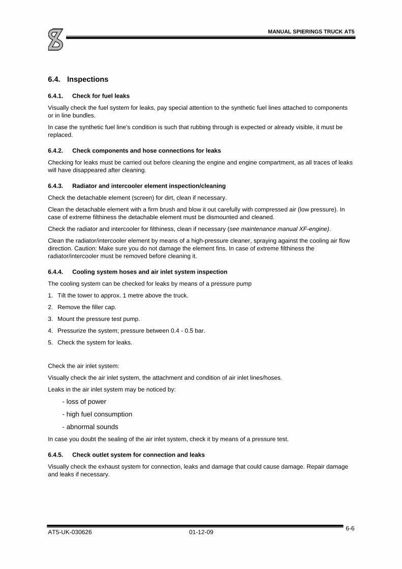
MANUAL SPIERINGS TRUCK AT5
AT5-UK-030626 01-12-09 6-6
6.4. Inspections
6.4.1. Check for fuel leaks
Visually check the fuel system for leaks, pay special attention to the synthetic fuel lines attached to components or in line bundles.
In case the synthetic fuel line's condition is such that rubbing through is expected or already visible, it must be replaced.
6.4.2. Check components and hose connections for leaks
Checking for leaks must be carried out before cleaning the engine and engine compartment, as all traces of leaks will have disappeared after cleaning.
6.4.3. Radiator and intercooler element inspection/cleaning
Check the detachable element (screen) for dirt, clean if necessary.
Clean the detachable element with a firm brush and blow it out carefully with compressed air (low pressure). In case of extreme filthiness the detachable element must be dismounted and cleaned.
Check the radiator and intercooler for filthiness, clean if necessary (see maintenance manual XF-engine).
Clean the radiator/intercooler element by means of a high-pressure cleaner, spraying against the cooling air flow direction. Caution: Make sure you do not damage the element fins. In case of extreme filthiness the radiator/intercooler must be removed before cleaning it.
6.4.4. Cooling system hoses and air inlet system inspection
The cooling system can be checked for leaks by means of a pressure pump
1. Tilt the tower to approx. 1 metre above the truck.
2. Remove the filler cap.
3. Mount the pressure test pump.
4. Pressurize the system; pressure between 0.4 - 0.5 bar.
5. Check the system for leaks.
Check the air inlet system:
Visually check the air inlet system, the attachment and condition of air inlet lines/hoses.
Leaks in the air inlet system may be noticed by:
- loss of power
- high fuel consumption
- abnormal sounds
In case you doubt the sealing of the air inlet system, check it by means of a pressure test.
6.4.5. Check outlet system for connection and leaks
Visually check the exhaust system for connection, leaks and damage that could cause damage. Repair damage and leaks if necessary.

MANUAL SPIERINGS TRUCK AT5
AT5-UK-030626 01-12-09 6-7
6.4.6. Check coolant antifreeze concentration
While the coolant is warm, there is overpressure in the cooling system. In this case, first relieve the pressure by carefully opening the filler cap one turn.
Coolant is a harmful substance. Prevent it from getting into contact with the skin.
Check the antifreeze concentration:
Coolant exists of water and anti corrosion agent and, if necessary, an antifreeze agent. As antifreeze agent you can use i.e. ethylene glycol.
Check the coolant antifreeze content. If necessary, add antifreeze to the cooling system.
Refer to the producer's instructions for the proper mixing ratio of the antifreeze. Apply preferably 40% antifreeze on ethylene glycol basis. As this not only guarantees a reliable protection against frost, it also guarantees a good protection against corrosion.
6.5. The clutch and gearbox
6.5.1. Specification gearbox
The ZF 16S-221 gearbox, installed in the AT5, has sixteen gears forward and two gears reverse. The gearbox has an integrated fluid torque converter and a retarder.
The gearbox shifts automatically (by means of air pressure) between the low and high range.
The dry disc clutch (F&S) between engine and gearbox is single. The operation is hydraulic and air powered. On the gearbox, a hydraulic pump is installed, which is switched on continuously, and is intended for the suspension and outrigger system.
To prevent gearing down to the lower range at too high a speed, an extra valve is mounted on the gearbox.
6.5.2. Fluid torque converter
The fluid torque converter consists of a pump paddle wheel (P), a turbine paddle wheel (T) and a reaction wheel (R, See Picture 6-8). The pump paddle wheel is driven by the engine and converts the mechanical energy into flow of the oil. The turbine paddle wheel is connected to the ingoing shaft of the gearbox. The turbine paddle wheel bends the oil flow. The reaction is a moment. The reaction wheel also has paddles. These paddles also cause a moment which increases the moment to the gearbox.

MANUAL SPIERINGS TRUCK AT5
AT5-UK-030626 01-12-09 6-8
Picture 6-8
The ratio between the torque of the turbine wheel and the pump wheel is called the torque enlargement. The ratio is bigger when the numbers of revs are more different.
So the torque is maximal, when the turbine wheel is standing still. At the moment the number of revs of the turbine wheel is 80% of the number of revs of the pump wheel, there isn’t any torque enlargement. The converter will be bridged automatically by the bridging clutch. Also, the converter only functions in its ideal domain of maximal output.
6.5.3. Bridging clutch
The bridging clutch is a hydraulic clutch and is placed before the torque converter (See Picture 6-8). The bridging clutch makes a mechanical connection between the engine and the gearbox. The converter is not active when the clutch is engaged.
6.5.4. Freewheel clutch
The integrated freewheel clutch applies when the carrier has to slow down without using any brake. The freewheel clutch applies and makes a mechanical connection between the engine and the gearbox. Now the engine is slowing down the carrier.

MANUAL SPIERINGS TRUCK AT5
AT5-UK-030626 01-12-09 6-9
6.5.5. Retarder
The retarder is placed between the torque converter and the clutch. The retarder consists of:
A stator, connected to the gearbox housing.
A rotor, connected to the ingoing shaft of the gearbox.
Pneumatic and hydraulic components to regulate the retarder.
The retarder is partially filled with oil. The rotor is driven by the movement of the vehicle. The oil, driven by the rotor is decelerated by the stator. Because of this the rotor will also be decelerated, and the crane also.
Using the retarder and torque converter will heat the oil. To cool down, the oil is lead through a heat exchanger. The coolant used to cool the oil is the same that is used to cool down the engine.
6.5.6. Clutch
This clutch is placed behind the retarder and can be engaged by the driver. This clutch is used to shift gears.
6.6. Carrying out maintenance work gearbox and clutch
6.6.1. Bleeding Gearbox
The gearbox heats up during operation. This causes overpressure, which must be relieved through the breather (No.2 in Picture 6-9). Make sure the breather is clean and it doesn't have a cap on it.
Check oil level gearbox and torque converter
Caution!
Make sure the engine is running when yout check the oil level, that the 8th gear is shifted and that the parking-brake is engaged!
Don’t check the level immediately after operation to avoid measurement-errors. The oil has to cooled down to approx. 30-40°C
Let the engine run idle for approx. 3 minutes. (neutral gear)
Remove the overflow plug (3).
Top up when the level is beneath the filling hole (3) (Picture 6-9). (see “Technical data” for oil specification)
Picture 6-9

MANUAL SPIERINGS TRUCK AT5
AT5-UK-030626 01-12-09 6-10
6.6.2. Drain oil gearbox
The oil must be drained while it is still warm. To drain, remove drain plugs of the converter (5) and the gearbox (6).
It is not possible to drain all of the oil. But by removing plug A (See Picture 6-10 (bottom view)) you can remove some more oil (approx. 7 litres). After doing so approx. 6 litres remains in the housing.
After cleaning the drain plugs, they may be reinstalled (the plugs involved are conical, self-sealing plugs).
Picture 6-10 (bottom view)
6.6.3. Filling gearbox and converter with oil
1. Remove oil filler plug (1)
2. Fill up approx. 10 litres. (16 litres when filling the first time)
3. Use transmission oil (See “TECHNICAL DATA”)
4. Fill up to the filler edge, with the engine running, shifted in 8th gear and parking brake engaged.
5. Replace filling plug (1) and overflow plug (3)
6. Shift to neutral gear and let the engine run at 1200 rpm for a few minutes so the oil can distribute.
7. Repeat the actions of point 4 and close hole 3 when no oil is running out.
6.6.4. Change / clean oil filter
In the converter a suction filter is mounted (B, See Picture 6-10 (bottom view)). The filter has to be cleaned every time the oil is changed.
The filter can be cleaned the easiest by flowing clean fuel through the filter with air-pressure.
You also can use a special brush to clean filters. Be careful that the inside of the filter doesn’t get polluted. Replace the filter in case of severe pollution.
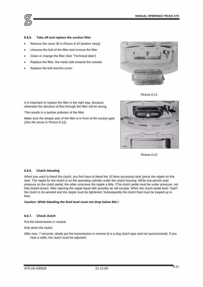
MANUAL SPIERINGS TRUCK AT5
AT5-UK-030626 01-12-09 6-11
6.6.5. Take off and replace the suction filter
Remove the cover (B in Picture 6-10 (bottom view))
Unscrew the bolt of the filter and remove the filter
Clean or change the filter (See “Technical data”)
Replace the filter, the metal side towards the outside.
Replace the bolt and the cover.
Picture 6-11
It is important to replace the filter in the right way, because otherwise the direction of flow through the filter will be wrong.
This results in a quicker pollution of the filter.
Make sure the deeper part of the filter is in front of the suction gate (See the arrow in Picture 6-12).
Picture 6-12
6.6.6. Clutch bleeding
When you want to bleed the clutch, you first have to bleed the 10 litres accessory tank (press the nipple on this tank. The nipple for the clutch is on the operating cylinder under the clutch housing. While one person puts pressure on the clutch pedal, the other unscrews the nipple a little. (The clutch pedal must be under pressure, not fully kicked down). After opening the nipple liquid with possibly air will escape. When the clutch pedal feels "hard", the clutch is de-aerated and the nipple must be tightened. Subsequently the clutch fluid must be topped up to Max.
Caution: While bleeding the fluid level must not drop below Min.!
6.6.7. Check clutch
Put the transmission in neutral.
Kick down the clutch.
After max. 7 seconds, slowly put the transmission in reverse (it is a dog clutch type and not synchronized). If you hear a rattle, the clutch must be adjusted.

MANUAL SPIERINGS TRUCK AT5
AT5-UK-030626 01-12-09 6-12
6.7. The transfer case
6.7.1. Specification transfer case
The transfer case is a STEYR type VG2001/396. This transfer case divides the power at the inlet (No.1, by means of a cardan shaft connected to the driven shaft of the gearbox) over two outlets. One outlet at the front side for driving axle 2 and 3 (No. 2), the other at the rear end side for axle 4 (No.3). The transfer case has two transmission ratios, high and low (0.89 and 1.536). You can shift between them pneumatically; shift only when the truck stands still.
The front and rear axles are driven by the transfer case through a longitudinal differential.
Picture 6-13
To the transfer case auxiliary outlet a hydraulic pump is connected, which serves as emergency steering pump if the engine breaks down (No.5). This pump only works when the transfer case driven shafts are running, so only while the vehicle travels.
Also the generator is driven by this transfer case (No.4).
6.8. Carrying out maintenance work transfer case
6.8.1. Bleeding
The breather (1) must be kept clean so the overpressure building up in the transfer case during operation, can escape (See Picture 6-14).
6.8.2. Check oil level
Check the oil level by unscrewing the oil level check plug (2). To prevent measuring errors, the check must not be carried out immediately after operation; wait some time until the oil is settled and cooled down. If the oil level is below the oil level hole, oil must be topped up.
6.8.3. Change oil in transfer case
The oil must be drained while it is still warm. Remove the drain plugs (3 and 4). After cleaning the drain plugs must be fitted with new seal rings 22x27 and reinstalled.
When the oil filler plug (5) and oil level check plug (2) are removed, the transfer case can be filled with approx. 6.5 litres new oil (see “technical data) until the oil level is at the check hole.
Picture 6-14
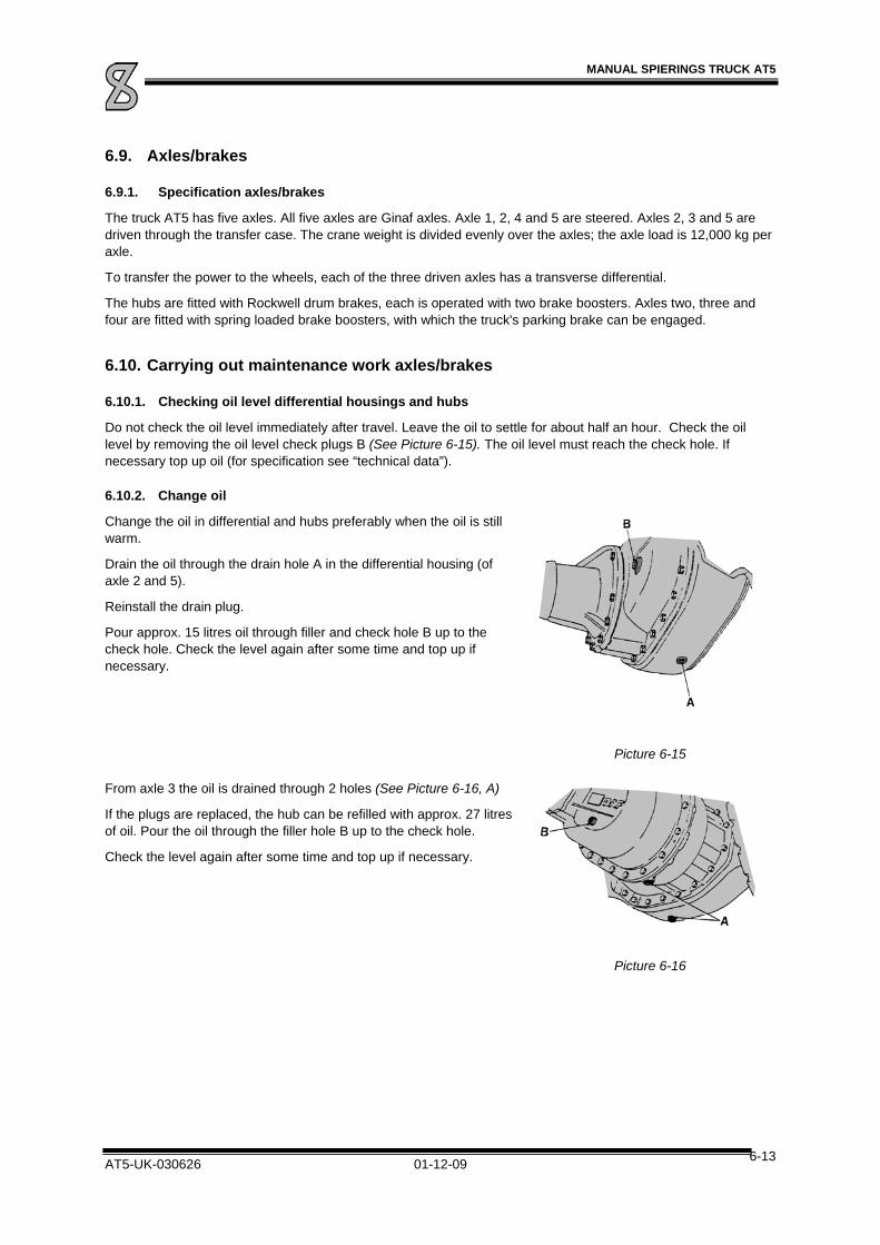
MANUAL SPIERINGS TRUCK AT5
AT5-UK-030626 01-12-09 6-13
6.9. Axles/brakes
6.9.1. Specification axles/brakes
The truck AT5 has five axles. All five axles are Ginaf axles. Axle 1, 2, 4 and 5 are steered. Axles 2, 3 and 5 are driven through the transfer case. The crane weight is divided evenly over the axles; the axle load is 12,000 kg per axle.
To transfer the power to the wheels, each of the three driven axles has a transverse differential.
The hubs are fitted with Rockwell drum brakes, each is operated with two brake boosters. Axles two, three and four are fitted with spring loaded brake boosters, with which the truck's parking brake can be engaged.
6.10. Carrying out maintenance work axles/brakes
6.10.1. Checking oil level differential housings and hubs
Do not check the oil level immediately after travel. Leave the oil to settle for about half an hour. Check the oil level by removing the oil level check plugs B (See Picture 6-15). The oil level must reach the check hole. If necessary top up oil (for specification see “technical data”).
6.10.2. Change oil
Change the oil in differential and hubs preferably when the oil is still warm.
Drain the oil through the drain hole A in the differential housing (of axle 2 and 5).
Reinstall the drain plug.
Pour approx. 15 litres oil through filler and check hole B up to the check hole. Check the level again after some time and top up if necessary.
Picture 6-15
From axle 3 the oil is drained through 2 holes (See Picture 6-16, A)
If the plugs are replaced, the hub can be refilled with approx. 27 litres of oil. Pour the oil through the filler hole B up to the check hole.
Check the level again after some time and top up if necessary.
Picture 6-16

MANUAL SPIERINGS TRUCK AT5
AT5-UK-030626 01-12-09 6-14
The hubs have one filler/drain (plug A) and an oil level check (plug B).
Drain the old oil by turning the drain hole downwards and removing the filler/drain plug.
Now turn the hole upwards and fill the hub up to the hole with approx.1.1 litre oil. While doing this, take into account that the oil needs some time to spread over the hub.
Picture 6-17
6.10.3. Check the brake lining thickness
To check the brake lining thickness, remove the synthetic sealing caps at the rear of the brake drums (See Picture 6-18). Now you can check if the brake lining is still sufficient. If in doubt make use of the wear ridge to check. Proceed by first supporting the crane on outriggers and removing the wheels. Subsequently unscrew the 3 fixing bolts on the brake drums. Then the brake drum is pushed from the hub by means of screwing 3 bolts M12x50 in the respective bores. Now check in view of the wear ridge how far the brake lining is worn and replace it if necessary (for specifications see “technical data”). The brake lining must be replaced at a thickness of approx. 8 mm
Picture 6-18
6.10.4. Brake test
We recommend doing a brake test once a year.
.

MANUAL SPIERINGS TRUCK AT5
AT5-UK-030626 01-12-09 7-1
7. The hydraulic system
7.1. Structure hydraulic system
The hydraulic diagram shows how the hydraulic system is built up (see enclosure). The hydraulic system exists of 4 subsystems, i.e.:
Hydraulic pump system
Hydraulic steering system
Hydraulic suspension
Hydraulic outrigger system
Below the various subsystems are dealt with separately.
7.1.1. Hydraulic pump system
The pump system exists of 3 pumps (see survey in the enclosures).
pump 1. The steering pump mounted on the DAF engine, supplies oil to steering circuit 1. Behind the steering pump a pressure relief valve is mounted, which limits the pressure to 150 bar.
pump 2. This (main steering) pump is connected to the engine (with a geared belt), and together with pump 3 supplies oil to steering circuit 2, the suspension and the outrigger-system. This pump is running continuously while the engine is running. The oil pressure is limited by a pressure valve; 150 bar while steering, 200 bar while operating the outriggers and suspension and 300 bar by using the first axle drive.
pump 3. The emergency steering pump is connected to the transfer case, so it only works while the vehicle is moving. This pump provides oil pressure for the steering system together with pump 2. The flow is regulated (max. 25 ltr/min). In case of a malfunction in the main steering pump, this pump takes over. The crane has sufficient steering power until it stops.
The return oil of pressure relief, flow control valve and hydraulic steering system flows in the hydraulic tank.

MANUAL SPIERINGS TRUCK AT5
AT5-UK-030626 01-12-09 7-2
7.1.2. Hydraulic steering system
Picture 7-1 shows how the steering system is built-up. In the steering gear housing (A) the turning motion of the steering wheel is mechanically converted to the motion of the steering rods (B). These in turn operate the steering arms (C), whereas the 4th and 5th axle steers opposite compared to the first and second axle. This provides a small turning circle.
For power steering a two-circuit ZF servo control is used. The steering wheel motion is converted to a hydraulic power steering, which operates the steering mechanism. To this end the steering axles have hydraulic auxiliary steering cylinders (D) each (also refer to the scheme in the enclosures).
Picture 7-1
To prevent unstable driving, a ‘spring-axle’ is placed between axle 3 and 4 (F). This spring-axle makes that axle 4 and 5 will not steer when steering just a little.
Also the auxiliary steering cylinders of axle 4 and 5 should not be activated when steering just al little. Therefore a brake valve is connected to the auxiliary steering cylinders on the rear axle. By this valve, the rear axles only steer when a certain pressure is built up. Therefore, the rear axles react slower when taking a bend, securing better steering qualities.
When returning the steering wheel the brake valve is bridged by a signal from the middle position arm (E) and the axle will follow the steering without delay. (Also refer to the hydraulic diagram in the enclosures)

MANUAL SPIERINGS TRUCK AT5
AT5-UK-030626 01-12-09 7-3
7.1.3. Hydraulic suspension
The AT5 has a hydro-pneumatic suspension with hydraulic cylinders which are connected to ten accumulators (see the hydraulic diagram in the enclosures). The accumulators are fitted with a bellows filled with gas (pressure 110 bar), which is compressed when the suspension cylinder moves in. This provides the spring motion. The oil flowing in and out of the cylinders flows through a throttle which provides damping.
The oil flow can be cut off with hydraulic 2/2-control valves. Thus the suspension is blocked.
7.1.4. Hydraulic outrigger system
To operate the outrigger system, the outrigger beams as well as the outriggers can be operated separately. The outrigger cylinders are fitted with controlled non-return valves, so in case of a burst hose, there is no loss of pressure in the outrigger cylinder (see the hydraulic diagram in the enclosures).
7.1.5. Hydraulic drive axle 1 (option)
The drive consists of (See Picture 7-2):
1. Hydraulic motor
2. planetary gearing
3. Pneumatically engaged coupling
4. A cardan shaft is mounted to this flange. The cardan shaft drives axle 1.
The hydraulic motor is driven by the oil pressure of the main pump.
Picture 7-2
7.2. Maintenance Hydraulic System
All parts of the hydraulic system are built for a long service life without to much maintenance. Spierings advises you to adhere to the following maintenance plan:
Replacing the fine filter and return oil filter:
First time after 400 hours.
Further every year.
Change hydraulic oil:
Every 5 years (after oil sample analysis).
For the sake of safety the oil level, hydraulic hoses, lines, couplings and connections must be visually checked regularly. In case of leaks or damage the respective parts must be replaced.
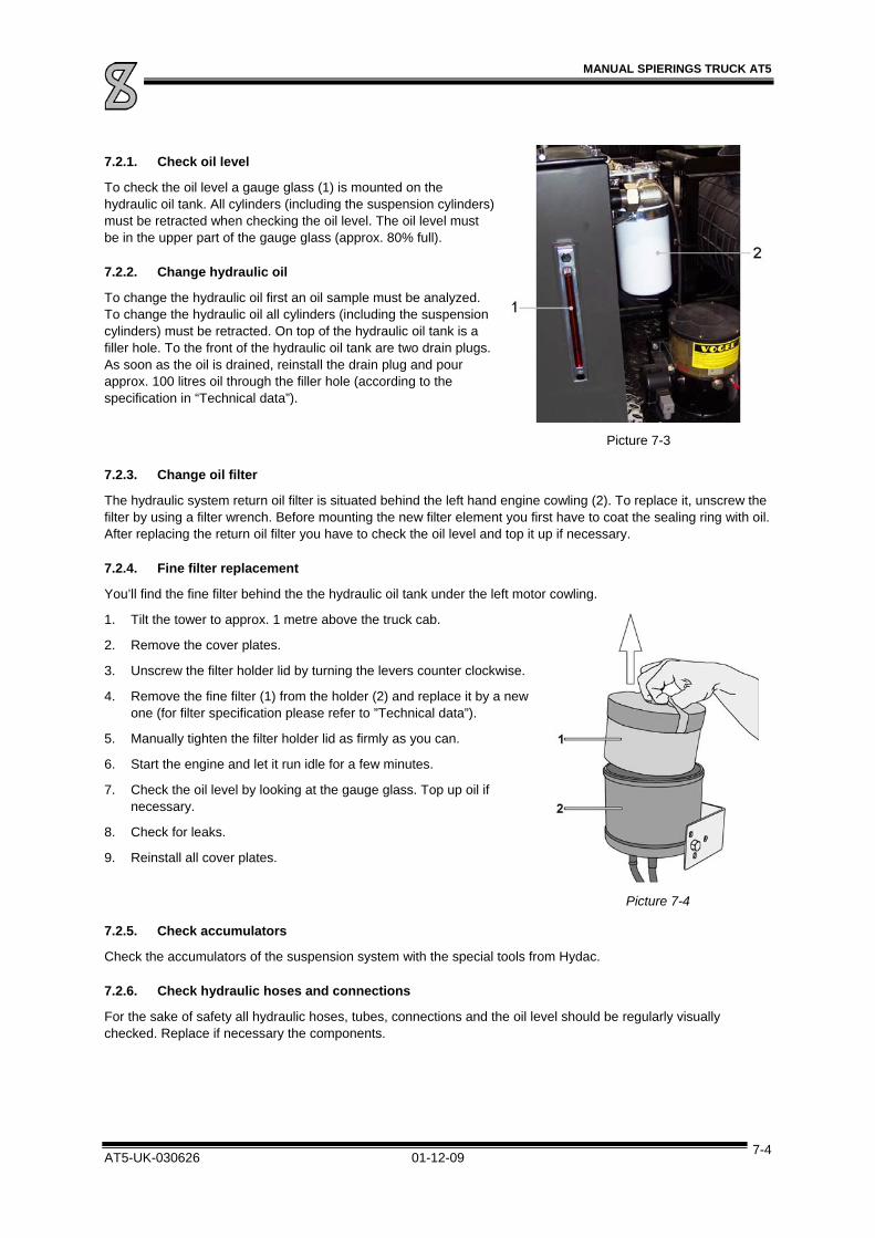
MANUAL SPIERINGS TRUCK AT5
AT5-UK-030626 01-12-09 7-4
7.2.1. Check oil level
To check the oil level a gauge glass (1) is mounted on the hydraulic oil tank. All cylinders (including the suspension cylinders) must be retracted when checking the oil level. The oil level must be in the upper part of the gauge glass (approx. 80% full).
7.2.2. Change hydraulic oil
To change the hydraulic oil first an oil sample must be analyzed. To change the hydraulic oil all cylinders (including the suspension cylinders) must be retracted. On top of the hydraulic oil tank is a filler hole. To the front of the hydraulic oil tank are two drain plugs. As soon as the oil is drained, reinstall the drain plug and pour approx. 100 litres oil through the filler hole (according to the specification in “Technical data”).
Picture 7-3
7.2.3. Change oil filter
The hydraulic system return oil filter is situated behind the left hand engine cowling (2). To replace it, unscrew the filter by using a filter wrench. Before mounting the new filter element you first have to coat the sealing ring with oil. After replacing the return oil filter you have to check the oil level and top it up if necessary.
7.2.4. Fine filter replacement
You’ll find the fine filter behind the the hydraulic oil tank under the left motor cowling.
1. Tilt the tower to approx. 1 metre above the truck cab.
2. Remove the cover plates.
3. Unscrew the filter holder lid by turning the levers counter clockwise.
4. Remove the fine filter (1) from the holder (2) and replace it by a new one (for filter specification please refer to ”Technical data”).
5. Manually tighten the filter holder lid as firmly as you can.
6. Start the engine and let it run idle for a few minutes.
7. Check the oil level by looking at the gauge glass. Top up oil if necessary.
8. Check for leaks.
9. Reinstall all cover plates.
Picture 7-4
7.2.5. Check accumulators
Check the accumulators of the suspension system with the special tools from Hydac.
7.2.6. Check hydraulic hoses and connections
For the sake of safety all hydraulic hoses, tubes, connections and the oil level should be regularly visually checked. Replace if necessary the components.
MANUAL SPIERINGS TRUCK AT5
AT5-UK-030626 01-12-09 8-1
8. The Steering System
The steering system is mechanical with hydraulic power steering. The system steers axles 1, 2, 4 and 5, whereas axle 4 and 5 are steered in opposite direction. This creates a small turning circle.
If, because of a malfunction, the main steering pump fails, the emergency steering pump on the gear shift high/low transfer case takes over. The crane remains controllable as long as it moves. However, it has to be stopped as soon as possible to remedy the malfunction. On the control panel, indicator lamp 1a (circuit 1) and 2a (circuit 2) show which circuit is defective.
8.1. Maintenance Steering System
8.1.1. Align
To prevent excessive tyre wear we advise you to align the truck every year. Please contact Spierings cranes for instructions.
8.1.2. Check steering arms and ball joints for play
Check this with help of another person. One turns the steering wheel gently from left to right a little. The other person checks the steering arms and ball joints for play.


MANUAL SPIERINGS TRUCK AT5
AT5-UK-030626 01-12-09 9-1
9. The Pneumatic System
9.1. Structure Pneumatic System
The pneumatic diagram in the enclosure shows how the pneumatic system is built up. The pressure is supplied by a compressor on the DAF engine.
The system can be divided into 2 subsystems:
1. The system for the truck brakes (approx. 9.8 bar for axle 1-3 and 7.8 bar for axle 4 and 5).
2. The system for the accessories (approx. 7 bar).
The system is secured by a 4-circuit safety valve. If there is a leak in one of the circuits, this valve sees to it that the remaining circuits keep air pressure, so the truck brake can still be operated.
9.1.1. Braking System
The braking system has 5 air vessels for;
Brake circuit 1; braking axle 1 and 2
Brake circuit 2; braking axles 3, 4 and 5
The parking brake
Accessories
Regenerating the air-dryer
By stepping on the brake pedal the valves are operated with control air. The actual braking takes place by separate feeding pressure.
The parking brake operates on the basis of de-aeration. As soon as the brake lever is operated, the parking brake boosters on axles 2, 3 and 4 are bled, engaging the brakes.
9.1.2. Accessories
There is a separate circuit for pneumatically operated components of the drive system.
These components receive their air from the 10 litres accessory vessel through a pressure reducer with water separator and air lubricator.
The components operated by this circuit are:
Vacuum brake - close/open exhaust valve.
- Switching on/off fuel pump.
Gearbox: - power gear shifting.
- Shifting high/low range (gear shift).
- Shifting slow/fast splitter.
- Powering clutch.
- Engaging the retarder
Transfer case: - shifting gear high/low.
- Switching longitudinal differential lock.
- Switch on/off PTO.

MANUAL SPIERINGS TRUCK AT5
AT5-UK-030626 01-12-09 9-2
Axles: - switching transverse differential locks axles 2, 3 and 4.
- switching first axle drive (option)
Steering system - Cylinder (un-)locking the steering arm of axle 4.
9.2. Maintenance Pneumatic System
9.2.1. Change filter element air-dryer
Important for proper operation and long service life of the pneumatic system is a dry and clean compressed air condition. Contaminations in the pneumatic system must be prevented. If water joins the air, it can cause corrosion to various components, resulting in bad operation and a short service life of the components.
Therefore, the pneumatic system is fitted with an air dryer. It is situated under the middle engine cowling (See Picture 9-1). The air dryer filter must be replaced every 2 years (for type; refer to “Technical data”). It can be removed by means of a filter wrench. After the seal ring is oiled, the new filter can be installed.
Picture 9-1
9.2.2. Check air vessels
Also all air pressure hoses and connections must be checked regularly. In case of leaks or damage the concerned parts must be replaced.
Check the air vessels regularly (at least once a week and during the winter every day) for the presence of condensed water (see “weekly checks”).
9.2.3. Check the air lubricator / water separator
A unit is mounted for the lubrication of the pneumatic accessories (See Picture 9-2). The unit consists of a pressure reducing valve (nr.1), a water separator (nr.2) and a lubricator (nr.5),
Check the oil level in the air lubricator every 2 months. Top up the reservoir if the level is too low; Unscrew the bowl and top up with oil according to the specification in “Technical data”. The amount of added oil can be regulated by adjusting the screw on top of the unit (nr.4).
Drain the water separator if necessary; Turn the screw to neutral and push it. In neutral, the valve function is semi-automatic;
If there is pressure, the valve is closed.
If there is pressure, the water automatically is drained.
By turning the valve clockwise, you can close it.
Picture 9-2
9.2.4. Check brake pressure
Check the air-pressure of the brakes yearly. The pressure gauge can be connected to the connections on the brake boosters.
See “Technical data” and the pneumatic scheme for the pressure values.

MANUAL SPIERINGS TRUCK AT5
AT5-UK-030626 01-12-09 10-1
10. Electrical System
10.1. Structure Electrical System
The on-board voltage is 24 Volt. It is supplied by two 12 Volt 165 Ah batteries, series connected. They are charged by a 24 Volt AC dynamo, with a maximum charging current of 35 A. The batteries are situated under the right-hand engine cowling (refer “get to know the truck”).
With the battery switch at the left-hand side behind the truck-cab, the truck's electrical circuit can be cut off. I.e. it must be done in case of welding jobs on the truck.
Under the middle console in the truck is a terminal board, where the controls in the truck cab are connected. Under the left-hand engine cowling is a switch box with a print for controlling the outrigger-/suspension system.
In the enclosures you will find electrical diagrams of the truck.
10.1.1. Power for powering the crane
The truck is equipped with a generator to power the crane.
In the tool box on the back of the truck you’ll find a power box. To this power box you can connect an external power supply to power the crane (100 A during crane operation and 80 A during erecting and folding). If (sufficient) external power is lacking, the crane can also be powered by the built-in generator. This generator is driven by the DAF-engine.
It is also possible to branch off power. Namely two sockets for 230 V (16 A max.) and two sockets for 400 V (32 A max.).
In the enclosures you’ll find the electrical plan of the power box. A radiator is installed to keep the power box dry
The power is lead to the crane through the slide contacts. Also the signal of “tower onto truck” is going through the slide contact. (Refer also to the diagrams in the enclosures)
10.1.2. Fuses
You will find the fuses listed in the enclosures. In this list the Amperage of each fuse is stated as well as its function. Never replace a defective fuse by a stronger fuse, as this could result in short circuit or fire. Never remove a fuse in case of:
Turned on ignition.
Running engine.
Switched on user.
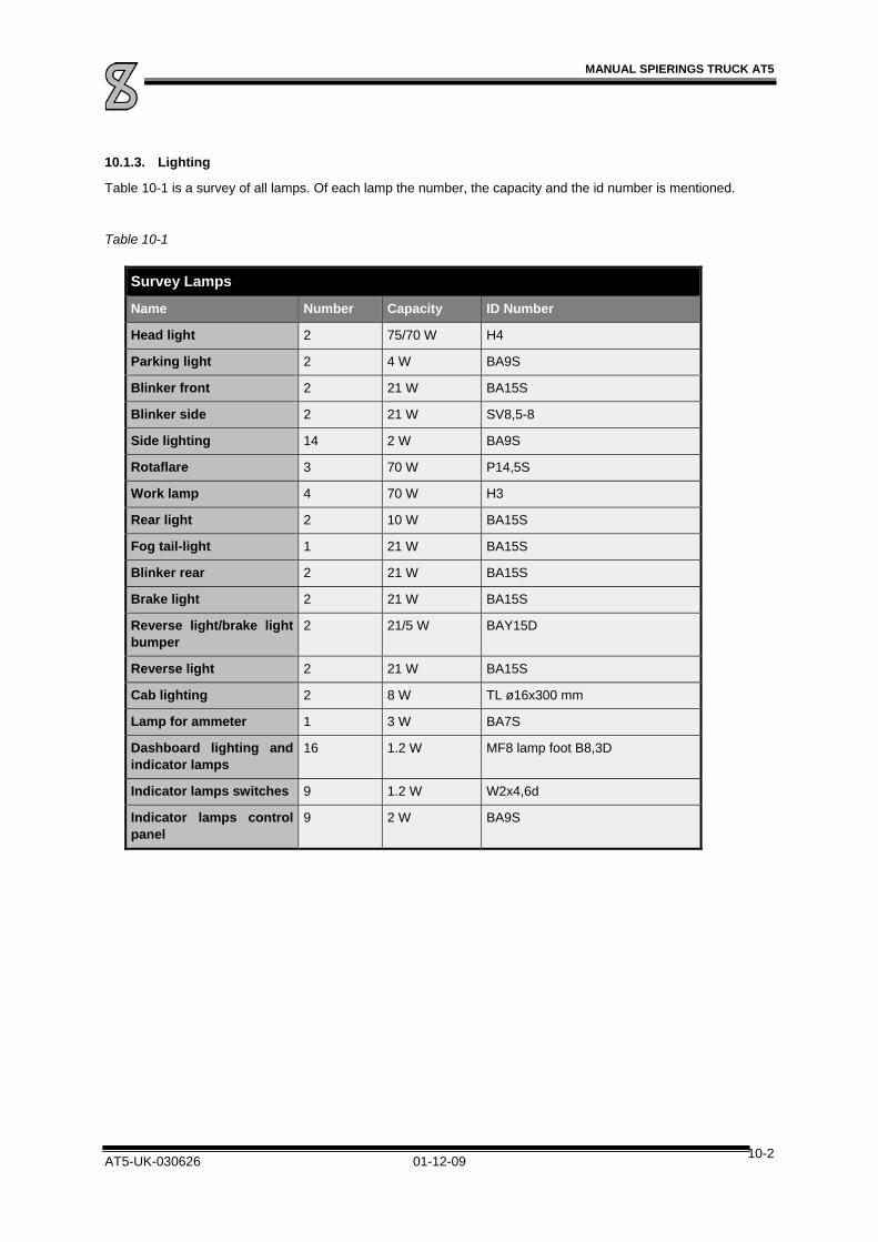
MANUAL SPIERINGS TRUCK AT5
AT5-UK-030626 01-12-09 10-2
10.1.3. Lighting
Table 10-1 is a survey of all lamps. Of each lamp the number, the capacity and the id number is mentioned.
Table 10-1
Survey Lamps
Name Number Capacity ID Number
Head light 2 75/70 W H4
Parking light 2 4 W BA9S
Blinker front 2 21 W BA15S
Blinker side 2 21 W SV8,5-8
Side lighting 14 2 W BA9S
Rotaflare 3 70 W P14,5S
Work lamp 4 70 W H3
Rear light 2 10 W BA15S
Fog tail-light 1 21 W BA15S
Blinker rear 2 21 W BA15S
Brake light 2 21 W BA15S
Reverse light/brake light bumper
2 21/5 W BAY15D
Reverse light 2 21 W BA15S
Cab lighting 2 8 W TL ø16x300 mm
Lamp for ammeter 1 3 W BA7S
Dashboard lighting and indicator lamps
16 1.2 W MF8 lamp foot B8,3D
Indicator lamps switches 9 1.2 W W2x4,6d
Indicator lamps control panel
9 2 W BA9S

MANUAL SPIERINGS TRUCK AT5
AT5-UK-030626 01-12-09 10-3
10.2. Maintenance Electrical System
The batteries maintenance exists of regularly checking the fluid level. If necessary it must be topped up with distilled water.
10.2.1. Charging batteries
You need a charger to charge the batteries and a cable with (2-pole) NATO-connector (charger and cable not provided). If you use a quick charger all battery ropes must be dismounted with regard to damage to electronic components. In case of a normal charger, this is not necessary.
1. Shut off the engine and remove the key from the ignition switch.
2. Remove the left-hand engine cowling.
3. Connect the connector to the charger and the socket on the truck. (Behind the left-handed engine cowling, beneath the hydraulic tank)
4. Switch on the charger.
5. After the charging is finished, you have to switch off the charger first.
6. Remove the connector.
7. Replace the engine cowling.
8. Start the engine and leave it running for a couple of minutes.
10.2.2. Batteries Replacement
Replace the batteries always by batteries of the same type and measurements.
1. Shut off the engine and remove the key from the ignition switch.
2. Remove the left-hand engine cowling.
3. Unscrew the wing nuts and remove the battery cover.
4. First disconnect terminal from pole on “-” pole side.
5. Subsequently disconnect the terminal from the “+” pole.
6. Remove the battery holder by unscrewing the nuts.
7. Remove the old batteries from the battery box and install the new ones in the same position.
8. Reinstall the battery holder and fasten it with the nuts.
9. First connect the “+” terminals and then the “-” terminals. Make sure the terminals are properly connected.
10. Properly grease the battery poles with Vaseline.
11. Replace the battery cover and fasten the wing nuts by hand.
12. Replace the engine cowling.
13. Start the engine and leave it running for a couple of minutes.


MANUAL SPIERINGS TRUCK AT5
AT5-UK-030626 01-12-09 11-1
11. Technical Data
Diesel engine Spierings No.
Engine oil SAE 15W40 ACEA E4-98
Oil filter (2x) MAN W950 SERV02100030
V-belt water pump, fan and dynamo drive
DAF No. 1388100 AVX 13x1225 La AADI09500030
V-belt hydraulic pump Synchroflex 32 AT20/1500 AADI09325150
Belt-tension gauge single belt Krikit I (DAF No. 1240442)
Belt-tension gauge twin-belt Krikit II (DAF No. 1240443)
Coolant SAE-J-1034 of ASTM D 3306
COOLELF PLUS 37’C
Air cleaner DAF No. 1353115 SERV03100080
Filter element air dryer Wabco 432.410.222.7 SERV05100010
Prefilter fuel Racor 490R (DAF No. 1296851) SERV04300010
Fuel filter DAF No. 247138 or MAN WK 962/4 SERV01100010
Starter motor Bosch JE 6,2 KW
Injector tools DAF No. 1329309 en 0694928
Gearbox
Oil gearbox (at delivery)
SAE 20W-20 AP/CF/ACEA E1-96 MIL-L-2104 ELF: PERFORMANCE XR30
Oil gearbox (after 400 h inspection at Spierings’)
SAE 20W-20 AP/CF/ACEA E1-96 MIL-L-2104 ELF: PERFORMANCE XR30
Clutch fluid Brake fluid DOT 4 ELF: Frelub 650
Filter element gearbox AAVE00150020
Gasket for gearbox-filter AAVE03200110
Transfer case
Oil transfer case (at delivery) SAE 80W90 API GL5/MIL-L-2105D
Oil transfer case (after 400 hours inspection at Spierings’)
ELF: TRANSELF SYNTHESE FE 75W90
Seal ring oil drain plug D.RING-A22x27-Cu DIN 07603
Axles/brakes/tyres
Oil axles (at delivery) ELF: TRANSELF SYNTHESE FE 75W90Quality API GL-5
Oil axles (after 400 hours inspection at Spierings’)
ELF: TRANSELF SYNTHESE FE 75W90Quality API GL-5
Brake fluid API GL5/MIL-L-2105D
Brake lining Ferodo 3652 F AAAS03000010R
Tyres 445/75 R22.5
Tyre pressure 7,5 bar
Rim 22,5" x 14"

MANUAL SPIERINGS TRUCK AT5
AT5-UK-030626 01-12-09 11-2
Hydraulics
Oil hydraulics ATF Dexron-IID, -IIE, -III or Mercon-M (±100 litres)
ELF: Elfmatic G3 22051
Return oil filter hydraulic system CS-15AN (OIIIT) HYIN04100211
Miscellaneous
Grease (general) EP2
Grease autom. lubricating system AVIA: Mystiek JT-6
Oil air lubricator ISO/UNI FD22 (e.g. Berulit 75)
Bolted connections
Driven axles 195 - 200 Nm
Bolts steering housing 560 Nm
Wheel hubs / axle stub 260 - 180 Nm
Steering plates swivel pin 300 Nm
Bolts steering rods 580 Nm
Castle nuts ball joints 340 Nm
Nut Pittman-arm 550 Nm
Wheel nuts 600 Nm
Generator axle 85 Nm
Bended ball joint 300 Nm
Bolts slewing ring 1480 Nm
Bolts motor support 300 Nm

MANUAL SPIERINGS TRUCK AT5
AT5-UK-030626 01-12-09 12-1
12. Enclosures
Enclosure 1
Hydraulics
Enclosure 2
Pneumatics
Enclosure 3
Electrical diagram’s
Enclosure 4
Electrical connections