Embed Size (px)
Citation preview

IN0JF-01
BO4111
Negative Cable
IN-10-INTRODUCTION FOR ALL OF VEHICLES
10Author: Date:
2004 LAND CRUISER (RM1071U)
FOR ALL OF VEHICLESPRECAUTION1. FOR VEHICLES EQUIPPED WITH SRS AIRBAG AND
SEAT BELT PRETENSIONER(a) The LAND CRUISER is equipped with an SRS (Supple-
mental Restraint System), such as the driver airbag, frontpassenger airbag assembly and seat belt pretensioner.Failure to carry out service operations in the correct se-quence could cause the supplemental restraint system tounexpectedly deploy during servicing, possibly leading toa serious accident.Further, if a mistake is made in servicing the supplementalrestraint system, it is possible the SRS may fail to operatewhen required. Before servicing (including removal orinstallation of parts, inspection or replacement), be sureto read the following items carefully, then follow the cor-rect procedure described in this manual.
(b) GENERAL NOTICE(1) Malfunction symptoms of the supplemental re-
straint system are difficult to confirm, so the diag-nostic trouble codes become the most importantsource of information when troubleshooting. Whentroubleshooting the supplemental restraint system,always inspect the diagnostic trouble codes beforedisconnecting the battery (See page DI-692 ).
(2) Work must be started after 90 seconds from thetime the ignition switch is turned to the ”LOCK” posi-tion and the negative (-) terminal cable is discon-nected from the battery.(The supplemental restraint system is equippedwith a back-up power source so that if work isstarted within 90 seconds of disconnecting the neg-ative (-) terminal cable from the battery, the SRSmay deploy.)When the negative (-) terminal cable is discon-nected from the battery, memory of the clock andaudio systems will be cancelled. So before startingwork, make a record of the contents memorized bythe each memory system. Then when work is fin-ished, reset the clock and audio systems as before.To avoid erasing the memory of each memory sys-tem, never use a back-up power supply from anoth-er battery.

F04784Marks
-INTRODUCTION FOR ALL OF VEHICLESIN-1 1
11Author: Date:
2004 LAND CRUISER (RM1071U)
(3) Even in cases of a minor collision where the SRSdoes not deploy, the steering wheel pad, front pas-senger airbag assembly, side airbag assembly, cur-tain shield airbag assembly and seat belt preten-sioner should be inspected (See page RS- 18,RS-32 , RS-47 , RS-60 and BO-143 ).
(4) Never use SRS parts from another vehicle. Whenreplacing parts, replace them with new parts.
(5) Before repairs, remove the airbag sensor if shocksare likely to be applied to the sensor during repairs.
(6) Never disassemble and repair the airbag sensor as-sembly, steering wheel pad, front passenger airbagassembly, side airbag assembly, curtain shield air-bag assembly or seat belt pretensioner in order toreuse them.
(7) If the airbag sensor assembly, steering wheel pad,front passenger airbag assembly, side airbag as-sembly, curtain shield airbag assembly or seat beltpretensioner have been dropped, or if there arecracks, dents or other defects in the case, bracketor connector, replace them with new ones.
(8) Do not directly expose the airbag sensor assembly,steering wheel pad, front passenger airbag assem-bly, side airbag assembly, curtain shield airbag as-sembly or seat belt pretensioner to hot air or flames.
(9) Use a volt/ohmmeter with high impedance (10 kΩ/Vminimum) for troubleshooting of the electrical cir-cuit.
(10) Information labels are attached to the periphery ofthe SRS components. Follow the instructions on thenotices.
(11) After work on the supplemental restraint system iscompleted, check the SRS warning light (See pageDI-692 ).
(c) SPIRAL CABLE (in Combination Switch)The steering wheel must be fitted correctly to the steeringcolumn with the spiral cable at the neutral position, other-wise cable disconnection and other troubles may result.Refer to SR-37 of this manual concerning correct steer-ing wheel installation.

B09710
Example:Correct Wrong
Z13950
Example:
IN-12-INTRODUCTION FOR ALL OF VEHICLES
12Author: Date:
2004 LAND CRUISER (RM1071U)
(d) STEERING WHEEL PAD (with Airbag)(1) When removing the steering wheel pad or handling
a new steering wheel pad, it should be placed withthe pad top surface facing up.Storing the pad with its metallic surface facing up-ward may lead to a serious accident if the airbag in-flates for some reason. In addition do not store asteering wheel pad on top of another one.
(2) Never measure the resistance of the airbag squib.(This may cause the airbag to deploy, which is verydangerous.)
(3) Grease should not be applied to the steering wheelpad and the pad should not be cleaned with deter-gents of any kind.
(4) Store the steering wheel pad where the ambienttemperature remains below 93°C (200°F), withouthigh humidity and away from electrical noise.
(5) When using electric welding, first disconnect the air-bag connector (yellow color and 2 pins) under thesteering column near the combination switch con-nector before starting work.
(6) When disposing of a vehicle or the steering wheelpad alone, the airbag should be deployed using anSST before disposal (See page RS-20 ).Carry out the operation in a safe place away fromelectrical noise.

B04200
Example:
Correct Wrong
Z13951
Example:
-INTRODUCTION FOR ALL OF VEHICLESIN-13
13Author: Date:
2004 LAND CRUISER (RM1071U)
(e) FRONT PASSENGER AIRBAG ASSEMBLY(1) Always store a removed or new front passenger air-
bag assembly with the airbag deployment directionfacing up.Storing the airbag assembly with the airbag deploy-ment direction facing down could cause a seriousaccident if the airbag inflates.
(2) Never measure the resistance of the airbag squib.(This may cause the airbag to deploy, which is verydangerous.)
(3) Grease should not be applied to the front passen-ger airbag assembly and the airbag door should notbe cleaned with detergents of any kind.
(4) Store the airbag assembly where the ambient tem-perature remains below 93°C (200°F), without highhumidity and away from electrical noise.
(5) When using electric welding, first disconnect the air-bag connector (yellow color and 2 pins) installed onthe assembly before starting work.
(6) When disposing of a vehicle or the airbag assemblyalone, the airbag should be deployed using an SSTbefore disposal (See page RS-34 ).Perform the operation in a safe place away fromelectrical noise.
B13205
Example:
Correct Wrong
B01929
Example:
IN-14-INTRODUCTION FOR ALL OF VEHICLES
14Author: Date:
2004 LAND CRUISER (RM1071U)
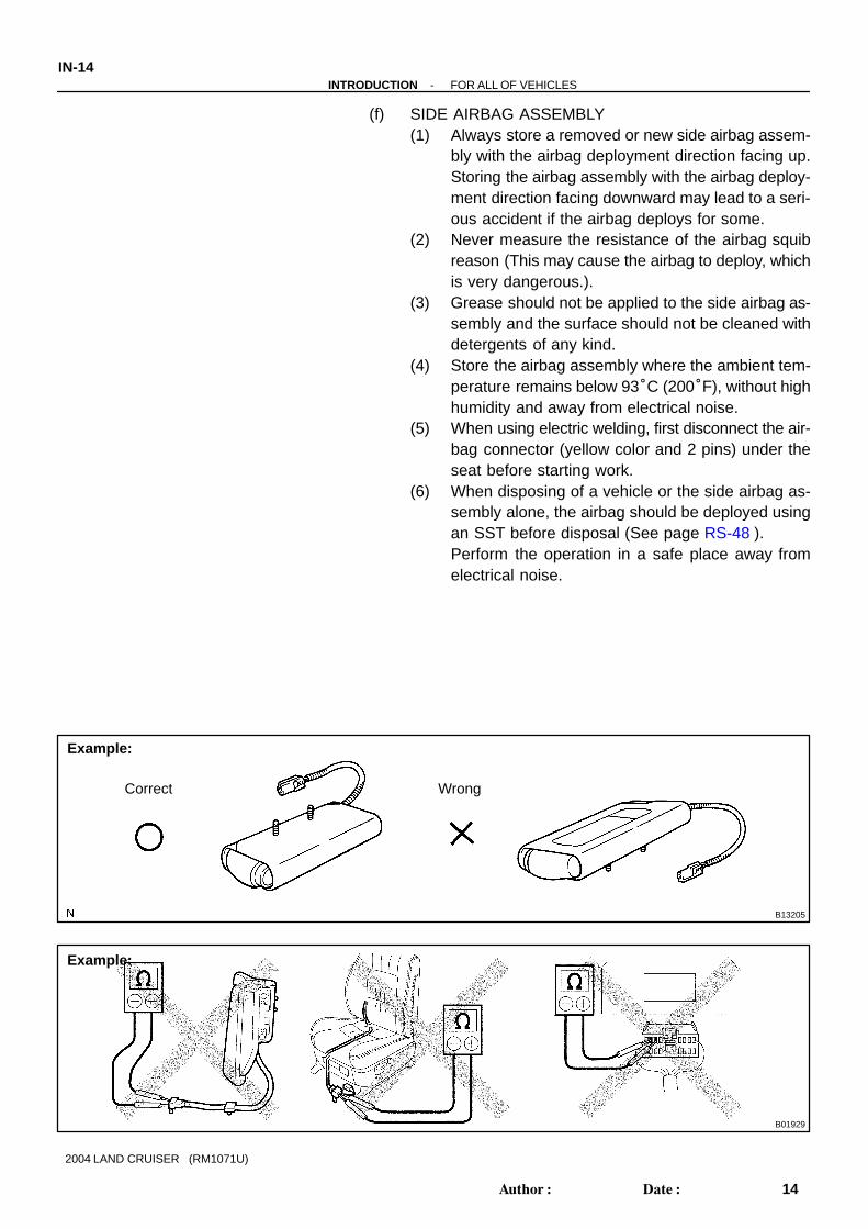
(f) SIDE AIRBAG ASSEMBLY(1) Always store a removed or new side airbag assem-
bly with the airbag deployment direction facing up.Storing the airbag assembly with the airbag deploy-ment direction facing downward may lead to a seri-ous accident if the airbag deploys for some.
(2) Never measure the resistance of the airbag squibreason (This may cause the airbag to deploy, whichis very dangerous.).
(3) Grease should not be applied to the side airbag as-sembly and the surface should not be cleaned withdetergents of any kind.
(4) Store the airbag assembly where the ambient tem-perature remains below 93°C (200°F), without highhumidity and away from electrical noise.
(5) When using electric welding, first disconnect the air-bag connector (yellow color and 2 pins) under theseat before starting work.
(6) When disposing of a vehicle or the side airbag as-sembly alone, the airbag should be deployed usingan SST before disposal (See page RS-48 ).Perform the operation in a safe place away fromelectrical noise.

B12627
Example: Correct Wrong
Clear Plastic Bag
R06952H12059 B08605
Example:
-INTRODUCTION FOR ALL OF VEHICLESIN-15
15Author: Date:
2004 LAND CRUISER (RM1071U)
(g) CURTAIN SHIELD AIRBAG ASSEMBLY(1) Always store a removed or new curtain shield air-
bag assembly in a clear plastic bag, and keep it ina safe place.
NOTICE:Protection bag is not reuse.CAUTION:Never disassemble the curtain shield airbag assembly.
(2) Never measure the resistance of the airbag squib(This may cause the airbag to deploy, which is verydangerous.).
(3) Grease should not be attached to the curtain shieldairbag assembly and the surface should not becleared with detergents of any kind.
(4) Store the airbag assembly where the ambient tem-perature remains below 93 °C (200 °F), withouthigh humidity and away from electrical noise.
(5) When using electric welding, first disconnect the air-bag connector (yellow color and 2 pins) into theinstrument panel before starting work.
(6) When disposing of a vehicle or the curtain shield air-bag assembly alone, the airbag should be deployedusing an SST before disposal (See page RS-61 ).Perform the operation in a safe place away fromelectrical noise.
B04210
Example:
IN-16-INTRODUCTION FOR ALL OF VEHICLES
16Author: Date:
2004 LAND CRUISER (RM1071U)
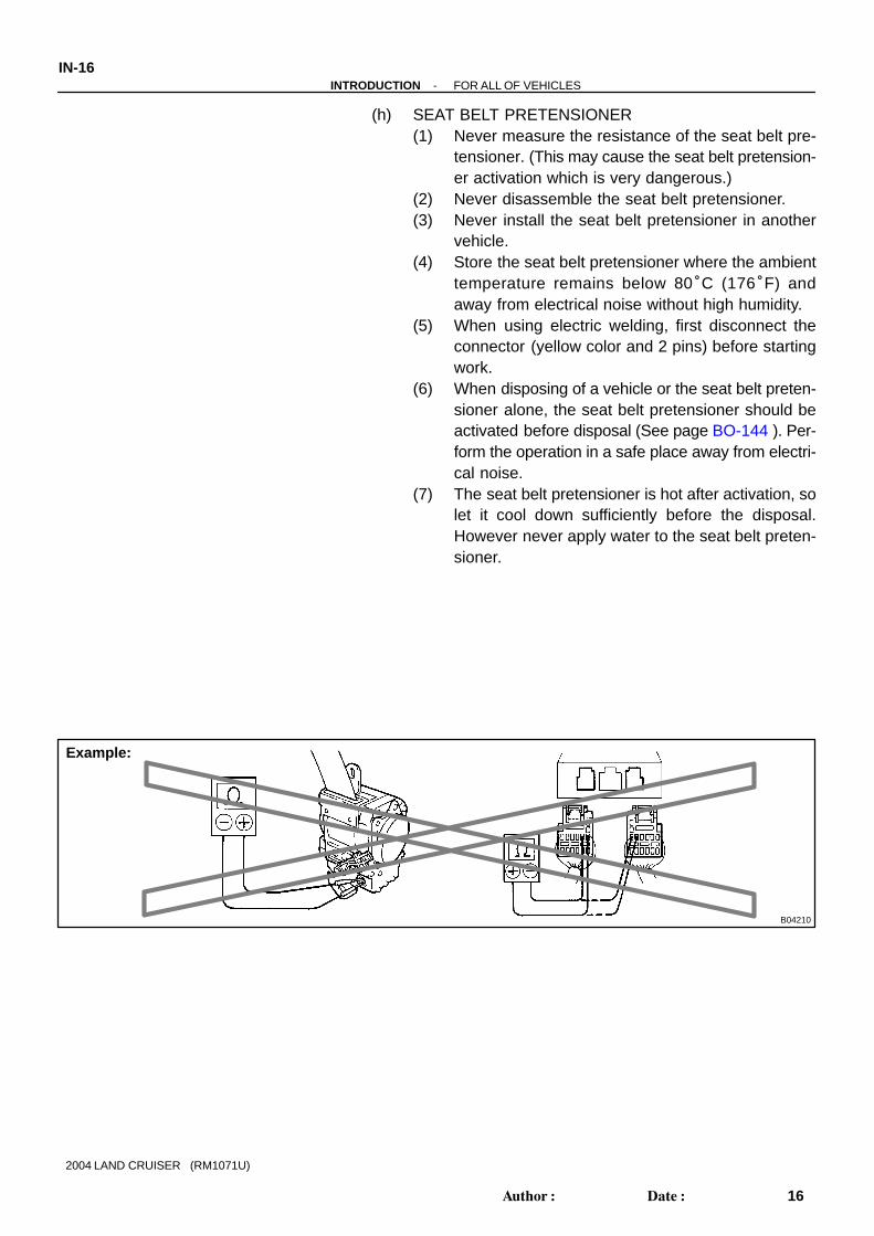
(h) SEAT BELT PRETENSIONER(1) Never measure the resistance of the seat belt pre-
tensioner. (This may cause the seat belt pretension-er activation which is very dangerous.)
(2) Never disassemble the seat belt pretensioner.(3) Never install the seat belt pretensioner in another
vehicle.(4) Store the seat belt pretensioner where the ambient
temperature remains below 80°C (176°F) andaway from electrical noise without high humidity.
(5) When using electric welding, first disconnect theconnector (yellow color and 2 pins) before startingwork.
(6) When disposing of a vehicle or the seat belt preten-sioner alone, the seat belt pretensioner should beactivated before disposal (See page BO-144 ). Per-form the operation in a safe place away from electri-cal noise.
(7) The seat belt pretensioner is hot after activation, solet it cool down sufficiently before the disposal.However never apply water to the seat belt preten-sioner.

-INTRODUCTION FOR ALL OF VEHICLESIN-17
17Author: Date:
2004 LAND CRUISER (RM1071U)
(i) AIRBAG SENSOR ASSEMBLY(1) Never reuse the airbag sensor assembly involved
in a collision when the SRS has deployed.(2) The connectors to the airbag sensor assembly
should be connected or disconnected with the sen-sor mounted on the floor. If the connectors are con-nected or disconnected while the airbag sensor as-sembly is not mounted to the floor, it could causeundesired ignition of the supplemental restraint sys-tem.
(3) Work must be started after 90 seconds from thetime the ignition switch is turned to the ”LOCK” posi-tion and the negative (-) terminal cable is discon-nected from the battery, even if only loosing the setbolts of the airbag sensor assembly.
(j) WIRE HARNESS AND CONNECTORThe SRS wire harness is integrated with the instrumentpanel wire harness assembly. The wires for the SRS wireharness are encased in a yellow corrugated tube and allthe connectors in the system are a standard yellow color.If the SRS wire harness becomes disconnected or theconnector becomes broken due to an accident, etc., re-pair or replace it as shown on page RS-96 .
F02201
N09214 F05476
E1
DLC1
CG
Ts DLC3
Ts
B04696
Center Differential LockIndicator Light
Center DifferentialSwitch
Transfer SelectLever
IN-18-INTRODUCTION FOR ALL OF VEHICLES
18Author: Date:
2004 LAND CRUISER (RM1071U)
2. FOR VEHICLE EQUIPPED WITH VEHICLE SKID CON-TROL (VSC) SYSTEM
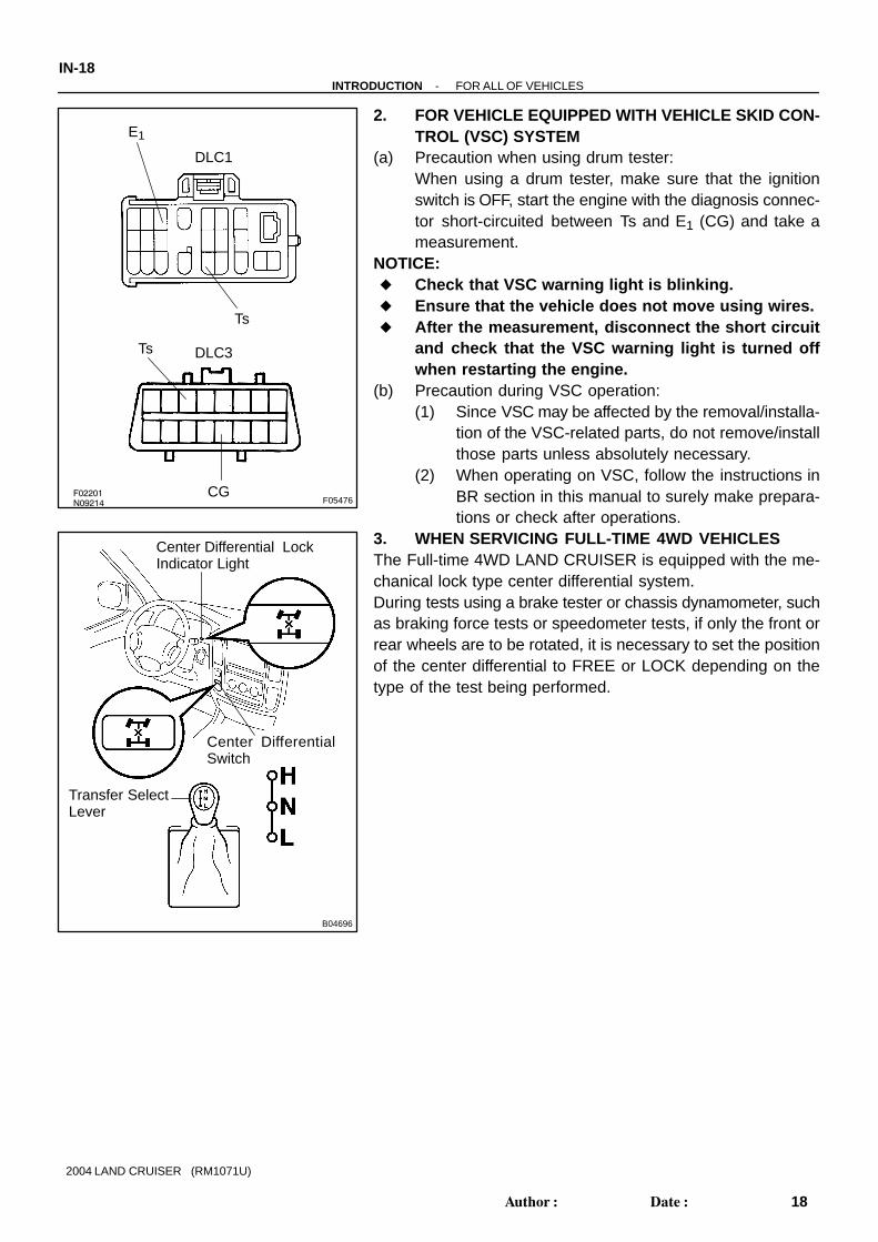
(a) Precaution when using drum tester:When using a drum tester, make sure that the ignitionswitch is OFF, start the engine with the diagnosis connec-tor short-circuited between Ts and E1 (CG) and take ameasurement.
NOTICE: Check that VSC warning light is blinking. Ensure that the vehicle does not move using wires. After the measurement, disconnect the short circuit
and check that the VSC warning light is turned offwhen restarting the engine.
(b) Precaution during VSC operation:(1) Since VSC may be affected by the removal/installa-
tion of the VSC-related parts, do not remove/installthose parts unless absolutely necessary.
(2) When operating on VSC, follow the instructions inBR section in this manual to surely make prepara-tions or check after operations.
3. WHEN SERVICING FULL-TIME 4WD VEHICLESThe Full-time 4WD LAND CRUISER is equipped with the me-chanical lock type center differential system.During tests using a brake tester or chassis dynamometer, suchas braking force tests or speedometer tests, if only the front orrear wheels are to be rotated, it is necessary to set the positionof the center differential to FREE or LOCK depending on thetype of the test being performed.

B04699
Indicator Light OFF
Lock
Rotate
Switch OFF
Indicator Light ON
Switch ON
Lock
Rotate
-INTRODUCTION FOR ALL OF VEHICLESIN-19
19Author: Date:
2004 LAND CRUISER (RM1071U)
Center differential FREE condition:
Condition Wheel
Center differential switch OFF A lifted wheel cannot be
Indicator light OFFrotated even if only one
wheel is lifted up as long
Transfer select lever (H/L)w/ VSC: Either will do
w/o VSC: H position only
wheel is lifted up, as long
as transmission is in N
position.
Center differential LOCK conditions (w/ VSC):
Condition Wheel
Center differential switch ON A lifted wheel cannot be
rotated even if only oneIndicator light ON
rotated even if only one
wheel is lifted up, as long
Transfer select lever (H/L) Either will doas transmission is in N
position.
Center differential LOCK conditions (w/o VSC):
Condition Wheel
Center differential switch ON A lifted wheel cannot be
rotated even if only oneIndicator light ON
rotated even if only one
wheel is lifted up, as long
Transfer select lever (H/L) H positionas transmission is in N
position.
Condition Wheel
Center differential switch ON or OFF A lifted wheel cannot be
rotated even if only oneIndicator light ON
rotated even if only one
wheel is lifted up, as long
Transfer select lever (H/L) L positionas transmission is in N
position.
HINT:w/o Vehicle skid control (VSC) system:When the transfer select lever is put in ”L” position, the centerdifferential is put in LOCK condition regardless of the positionof the center differential lock switch.CAUTION:Center differential ”LOCK” ↔ ”FREE” selecting proce-dure: Operate the switch only when all of 4 wheels are
stopped or driven in a straight line. Never operate the switch when any wheel is slipping. Never operate the switch when any wheel is spinning
freely. Never operate the switch when swerving or corner-
ing.HINT: Center differential ”LOCK” ↔ ”FREE” selecting proce-
dure:Move the vehicle forward or backward slightly if the indi-cator light does not operate correctly when the center dif-ferential lock switch is turned ON or OFF.

B04698
B04696
Center Differential LockIndicator Light
Center DifferentialSwitch
Transfer SelectLever
F08296
IN-20-INTRODUCTION FOR ALL OF VEHICLES
20Author: Date:
2004 LAND CRUISER (RM1071U)
Transfer gear ”H” ↔ ”L” gear shifting procedure:When shifting, always put the shift lever of the transmis-sion in N position. In other positions, the gears of thetransfer clash, and switching cannot be performed.
4. WHEN TESTING BRAKES, SPEEDOMETER, ETC.(a) When carrying out any kind of servicing or testing on a
Full-time 4WD in which the front or rear wheels are to berotated (braking test, speedometer test), be sure to ob-serve the precautions given below.Incorrect preparations or test procedures may cause dan-ger as well as unsuccessful test results.Before starting any such servicing or test, be sure tocheck the following items: Center differential mode position (FREE or LOCK)
Vehicle skid control (VSC) system (with or without):If the vehicle is equipped with the system, the slipindicator light, the VSC/TRAC indicator light and theVSC OFF indicator light come on with the ignitionkey turned to ”ON”. They will go off after about a fewseconds.
Whether wheels should be touching ground orjacked up
Transmission gear position (N position) Transfer gear position (H or L position) Maximum testing vehicle speed Maximum testing time
HINT:w/o Vehicle skid control (VSC) system:When the transfer select lever is put in ”L” position, the centerdifferential is put in LOCK condition regardless of the positionof the center differential lock switch.
B04201
B04202
-INTRODUCTION FOR ALL OF VEHICLESIN-21
21Author: Date:
2004 LAND CRUISER (RM1071U)
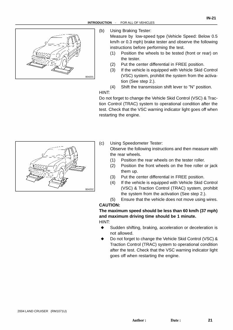
(b) Using Braking Tester:Measure by low-speed type (Vehicle Speed: Below 0.5km/h or 0.3 mph) brake tester and observe the followinginstructions before performing the test.(1) Position the wheels to be tested (front or rear) on
the tester.(2) Put the center differential in FREE position.(3) If the vehicle is equipped with Vehicle Skid Control
(VSC) system, prohibit the system from the activa-tion (See step 2.).
(4) Shift the transmission shift lever to ”N” position.HINT:Do not forget to change the Vehicle Skid Control (VSC) & Trac-tion Control (TRAC) system to operational condition after thetest. Check that the VSC warning indicator light goes off whenrestarting the engine.
(c) Using Speedometer Tester:Observe the following instructions and then measure withthe rear wheels.(1) Position the rear wheels on the tester roller.(2) Position the front wheels on the free roller or jack
them up.(3) Put the center differential in FREE position.(4) If the vehicle is equipped with Vehicle Skid Control
(VSC) & Traction Control (TRAC) system, prohibitthe system from the activation (See step 2.).
(5) Ensure that the vehicle does not move using wires.CAUTION:The maximum speed should be less than 60 km/h (37 mph)and maximum driving time should be 1 minute.HINT: Sudden shifting, braking, acceleration or deceleration is
not allowed. Do not forget to change the Vehicle Skid Control (VSC) &
Traction Control (TRAC) system to operational conditionafter the test. Check that the VSC warning indicator lightgoes off when restarting the engine.
B04203
B04204
IN-22-INTRODUCTION FOR ALL OF VEHICLES
22Author: Date:
2004 LAND CRUISER (RM1071U)
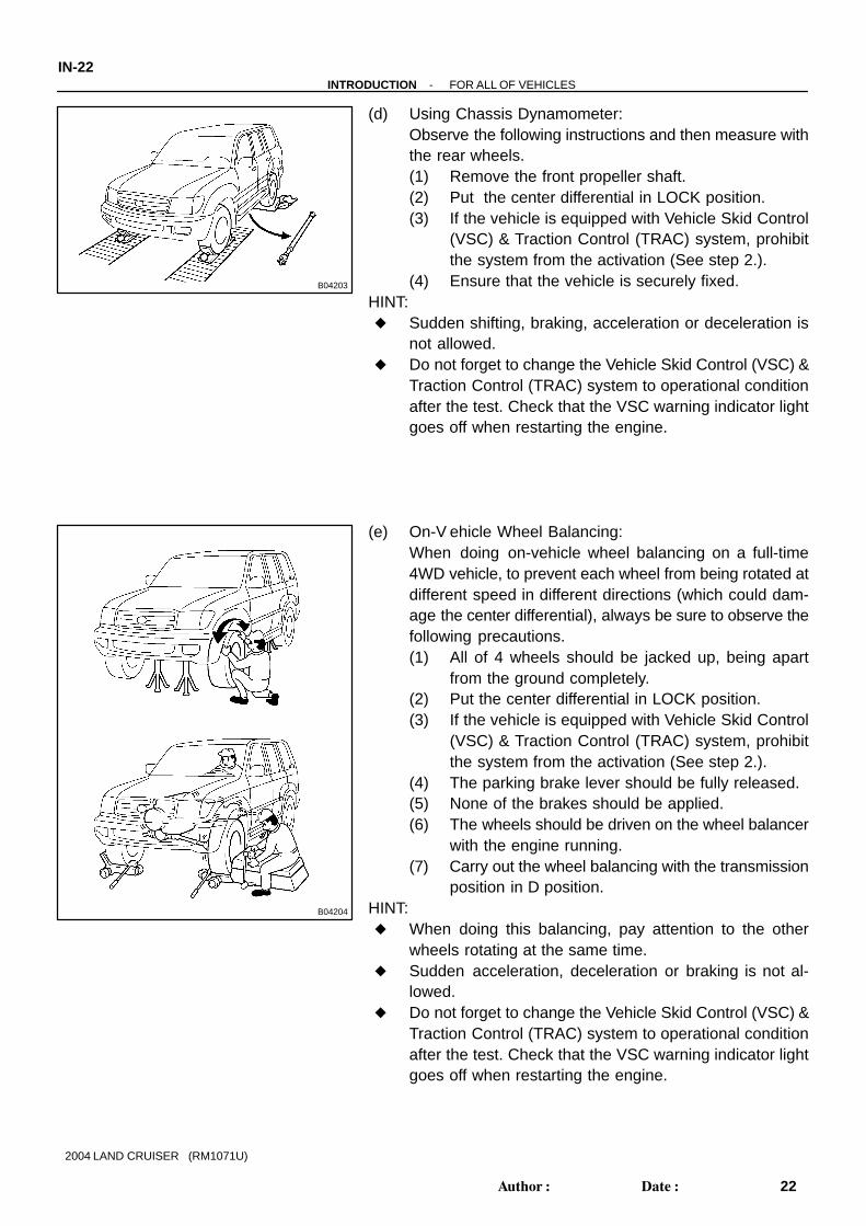
(d) Using Chassis Dynamometer:Observe the following instructions and then measure withthe rear wheels.(1) Remove the front propeller shaft.(2) Put the center differential in LOCK position.(3) If the vehicle is equipped with Vehicle Skid Control
(VSC) & Traction Control (TRAC) system, prohibitthe system from the activation (See step 2.).
(4) Ensure that the vehicle is securely fixed.HINT: Sudden shifting, braking, acceleration or deceleration is
not allowed. Do not forget to change the Vehicle Skid Control (VSC) &
Traction Control (TRAC) system to operational conditionafter the test. Check that the VSC warning indicator lightgoes off when restarting the engine.
(e) On-V ehicle Wheel Balancing:When doing on-vehicle wheel balancing on a full-time4WD vehicle, to prevent each wheel from being rotated atdifferent speed in different directions (which could dam-age the center differential), always be sure to observe thefollowing precautions.(1) All of 4 wheels should be jacked up, being apart
from the ground completely.(2) Put the center differential in LOCK position.(3) If the vehicle is equipped with Vehicle Skid Control
(VSC) & Traction Control (TRAC) system, prohibitthe system from the activation (See step 2.).
(4) The parking brake lever should be fully released.(5) None of the brakes should be applied.(6) The wheels should be driven on the wheel balancer
with the engine running.(7) Carry out the wheel balancing with the transmission
position in D position.HINT: When doing this balancing, pay attention to the other
wheels rotating at the same time. Sudden acceleration, deceleration or braking is not al-
lowed. Do not forget to change the Vehicle Skid Control (VSC) &
Traction Control (TRAC) system to operational conditionafter the test. Check that the VSC warning indicator lightgoes off when restarting the engine.

B04205
Conditions
Towing Method
1. Flat Bed Truck
Parking Brake
Any Position
2. Wheel Lift Type Truck
Applied
Transmission Shift LeverPosition
AppliedFrom Rear
Any Position
From Front
B04206
NO
NO
If this towing method is used, either from the front or rear:
Never tow the vehicle using a method where the lifted-up wheelcannot rotate.
Do not use the sling type towing method, either from the front or rear,as this method causes damage to the body.
(a) There is a danger of the drive train heating up and causing break-down, or of the wheels flying off the dolly.
(b) In addition, if the vehicle is equipped with the Vehicle Skid Control(VSC) & Traction Control (TRAC) system, the system will apply therotating wheels brake unless the engine isn’t shut off.
-INTRODUCTION FOR ALL OF VEHICLESIN-23
23Author: Date:
2004 LAND CRUISER (RM1071U)
5. WHEN TOWING FULL-TIME 4WD VEHICLES Use one of the methods shown below to tow the vehicle. If the vehicle has trouble in the chassis and drive train, use method 1 (flat bed truck).
NOTICE:Do not use any towing method other than those shown above. For example, the towing methods shown below are dangerous or damage the vehicle, so do not use
them.

IN-24-INTRODUCTION FOR ALL OF VEHICLES
24Author: Date:
2004 LAND CRUISER (RM1071U)
6. FOR VEHICLES EQUIPPED WITH A CATALYTIC CONVERTERCAUTION:If large amount of unburned gasoline flows into the converter, it may overheat and create a fire haz-ard. To prevent this, observe the following precautions and explain them to your customer.(a) Use only unleaded gasoline.(b) Avoid prolonged idling.
Avoid running the engine at idle speed for more than 20 minutes.(c) Avoid spark jump test.
(1) Perform spark jump test only when absolutely necessary. Perform this test as rapidly as possible.(2) While testing, never race the engine.
(d) Avoid prolonged engine compression measurement.Engine compression tests must be done as rapidly as possible.
(e) Do not run engine when fuel tank is nearly empty.This may cause the engine to misfire and create an extra load on the converter.
(f) Avoid coasting with ignition turned off and prolonged braking.(g) Do not dispose of used catalyst along with parts contaminated with gasoline or oil.
7. IF VEHICLE IS EQUIPPED WITH MOBILE COMMUNICATION SYSTEMFor vehicles with mobile communication systems such as two-way radios and cellular telephones, observethe following precautions.
(1) Install the antenna as far as possible away from the ECU and sensors of the vehicle’s electronicsystem.
(2) Install the antenna feeder at least 20 cm (7.87 in.) away from the ECU and sensors of the ve-hicle’s electronic systems. For details about ECU and sensors locations, refer to the section onthe applicable component.
(3) Do not wind the antenna feeder together with the other wiring as much as possible, also avoidrunning the antenna feeder parallel with other wire harnesses.
(4) Check that the antenna and feeder are correctly adjusted.(5) Do not install powerful mobile communications system.
8. FOR USING OBD II SCAN TOOL OR TOYOTA HAND-HELD TESTERCAUTION:Observe the following items for safety reasons: Before using the OBD II scan tool or TOYOTA hand-held tester, the OBD II scan tool’s instruc-
tion book or TOYOTA hand-held tester’s operator manual should be read thoroughly. Be sure to route all cables securely when driving with the OBD II scan tool or TOYOTA hand-
held tester connected to the vehicle. (i.e. Keep cables away from feet, pedals, steering wheeland shift lever.)
Two persons are required when test driving with the OBD II scan tool or TOYOTA hand-heldtester, one person to drive the vehicle and the other person to operate the OBD II scan tool orTOYOTA hand-held tester.

IN04S-46
-INTRODUCTION HOW TO TROUBLESHOOT ECU CONTROLLED SYSTEMS
IN-25
25Author: Date:
2004 LAND CRUISER (RM1071U)
HOW TO TROUBLESHOOT ECU CONTROLLED SYSTEMSGENERAL INFORMATIONA large number of ECU controlled systems are used in the LAND CRUISER. In general, the ECU controlledsystem is considered to be a very intricate system requiring a high level of technical knowledge and expertskill to troubleshoot. However, the fact is that if you proceed to inspect the circuits one by one, troubleshoot-ing of these systems is not complex. If you have adequate understanding of the system and a basic knowl-edge of electricity, accurate diagnosis and necessary repair can be performed to locate and fix the problem.This manual is designed through emphasis of the above standpoint to help service technicians perform ac-curate and effective troubleshooting, and is compiled for the following major ECU controlled systems:The troubleshooting procedure and how to make use of it are described on the following pages.
System Page
1. Engine DI-1
2. Automatic Transmission DI-358
3. ABS & Vehicle Stability Control (VSC) & Brake Assist (BA) System DI-502
4. Power Tilt and Power Telescopic Steering Column DI-656
5. Supplemental Restraint System DI-690
6. Wireless Door Lock Control System DI-936
7. Theft Deterrent System DI-953
8. Cruise Control System DI-979
9. Engine Immobiliser System DI-1002
10.Body Control System DI-1038
11.Driver Door Control System DI-1089
12.Multiplex Communication System DI-1127
13.Navigation System DI-1151
14.Rear View Monitor System DI-1268
15.Air Conditioning System DI-1300
FOR USING OBD II SCAN TOOL OR TOYOTA HAND-HELD TESTER Before using the scan tool or tester, the scan tool’s instruction book or tester’s operator manual should
be read thoroughly. If the scan tool or tester cannot communicate with ECU controlled systems when you have connected
the cable of the scan tool or tester to DLC3, turned the ignition switch ON and operated the scan tool,there is a problem on the vehicle side or tool side.(1) If communication is normal when the tool is connected to another vehicle, inspect the diagnosis
data link line (Busline) or ECU power circuit of the vehicle.(2) If communication is still not possible when the tool is connected to another vehicle, the problem
is probably in the tool itself, so perform the Self Test procedures outline in the Tester Operator’sManual.

IN04T-23
Vehicle Brought to Workshop
Customer ProblemAnalysis
Symptom Confirmationand Diagnostic TroubleCode Check
Symptom Simulation
Diagnostic Trouble Code Chart
Problem Symptoms Table
Circuit Inspection or PartsInspection
Repair
Confirmation Test
End
1
2
4
3
5
6
7
8
Ask the customer about the conditions and theenvironment when the problem occurred.
1
Confirm the symptoms and the problem conditions,and check the diagnostic trouble codes.(When the problem symptoms do not appear during confirmation, use the symptom simulationmethod described later on.)
2, 3
Check the results obtained in Step 2, then confirm the inspection procedure for the system or the partwhich should be checked using the diagnostictrouble code chart or the problem symptoms table.
4, 5, 6
Check and repair the affected system or part in accordance with the instructions in Step 6.
7
After completing repairs, confirm that the problem has been eliminated.(If the problem is not reproduced, perform theconfirmation test under the same conditions andin the same environment as when it occurred forthe first time.)
8
IN-26 -INTRODUCTION HOW TO TROUBLESHOOT ECU CONTROLLED SYSTEMS
26Author: Date:
2004 LAND CRUISER (RM1071U)
HOW TO PROCEED WITH TROUBLESHOOTINGCarry out troubleshooting in accordance with the procedure on the following page. Here, only the basic pro-cedure is shown. Details are provided in Diagnostics section, showing the most effective methods for eachcircuit. Confirm the troubleshooting procedures first for the relevant circuit before beginning troubleshootingof that circuit.

Important Points in the Customer Problem Analysis
What ----- Vehicle model, system name When ----- Date, time, occurrence frequency Where ----- Road conditions Under what conditions? ----- Running conditions, driving conditions, weather conditions
How did it happen? ----- Problem symptoms
(Sample) Engine control system check sheet.
ENGINE CONTROL SYSTEM Check Sheet
Customer’s Name
Driver’s Name
Data VehicleBrought in
License No.
Model and ModelYear
Frame No.
Engine Model
Odometer Readingkmmiles
Pro
blem
Sym
ptom
s
Engine doesnot Start
Difficult toStart
Poor Idling
PoorDrive ability
Engine Stall
Others
Engine does not crank No initial combustion No complete combustion
Engine cranks slowlyOther
Incorrect first idle Idling rpm is abnormal High ( rpm) Low ( rpm)Rough idling Other
Hesitation Back fire Muffler explosion (after-fire) SurgingKnocking Other
Soon after starting After accelerator pedal depressedAfter accelerator pedal released During A/C operationShifting from N to D Other
Data Problem
Constant Sometimes ( times per day/month)
Inspector’sName
CUSTOMER PROBLEM ANALYSIS CHECK
-INTRODUCTION HOW TO TROUBLESHOOT ECU CONTROLLED SYSTEMS
IN-27
27Author: Date:
2004 LAND CRUISER (RM1071U)
1. CUSTOMER PROBLEM ANALYSISIn troubleshooting, the problem symptoms must be confirmed accurately and all preconceptions must becleared away in order to give an accurate judgment. To ascertain just what the problem symptoms are, it isextremely important to ask the customer about the problem and the conditions at the time it occurred.Important Point in the Problem Analysis:The following 5 items are important points in the problem analysis. Past problems which are thought to beunrelated and the repair history, etc. may also help in some cases, so as much information as possible shouldbe gathered and its relationship with the problem symptoms should be correctly ascertained for referencein troubleshooting. A customer problem analysis table is provided in Diagnostics section for each systemfor your use.

DIAGNOSTIC TROUBLE CODE CHECK PROCEDURE
Diagnostic Trouble Code Check (Make anote of and then clear)
Confirmationof Symptoms
Diagnostic TroubleCode Check
Problem Condition
Diagnostic Trouble Code Display
Problem symptomsexist
Same diagnostictrouble code isdisplayed
Problem is still occurring in the diagnosticcircuit
Normal code isdisplayed
The problem is still occurring in a placeother than in the diagnostic circuit(The diagnostic trouble code displayedfirst is either for a past problem or it is asecondary problem)
No problem symptoms exist
The problem occurred in the diagnosticcircuit in the past
Normal Code Display Problem symptomsexist
Normal code is displayed
The problem is still occurring in a placeother than in the diagnostic circuit
No problem symptoms exist
Normal code is displayed
The problem occurred in a place otherthan in the diagnostic circuit in the past
IN-28 -INTRODUCTION HOW TO TROUBLESHOOT ECU CONTROLLED SYSTEMS
28Author: Date:
2004 LAND CRUISER (RM1071U)
2. SYMPTOM CONFIRMATION AND DIAGNOSTIC TROUBLE CODE CHECKThe diagnostic system in the LAND CRUISER fulfills various functions. The first function is the DiagnosticTrouble Code Check in which a malfunction in the signal circuits to the ECU is stored in code in the ECUmemory at the time of occurrence, to be output by the technician during troubleshooting. Another functionis the Input Signal Check which checks if the signals from various switches are sent to the ECU correctly.By using these check functions, the problem areas can be narrowed down quickly and troubleshooting canbe performed effectively. Diagnostic functions are incorporated in the following systems in the LAND CRUIS-ER.
SystemDiagnostic Trouble
Code Check
Input Signal Check
(Sensor Check)
Other Diagnosis
Function
Engine
Automatic Transmission
ABS & Vehicle Stability Control (VSC) & Brake Assist (BA) System
Power Tilt and Power Telescopic Steering Column
Supplemental Restraint System
Theft Deterrent System
Cruise Control System
Engine Immobiliser System
Driver Door Control System
Navigation System
Air Conditioning System
(with Test Mode)
(with Test Mode)
Cancel Signal
Check
In diagnostic trouble code check, it is very important to determine whether the problem indicated by the diag-nostic trouble code is still occurring or occurred in the past but returned to normal at present. In addition,it must be checked in the problem symptom check whether the malfunction indicated by the diagnostictrouble code is directly related to the problem symptom or not. For this reason, the diagnostic trouble codesshould be checked before and after the symptom confirmation to determine the current conditions, as shownin the table below. If this is not done, it may, depending on the case, result in unnecessary troubleshootingfor normally operating systems, thus making it more difficult to locate the problem, or in repairs not pertinentto the problem. Therefore, always follow the procedure in correct order and perform the diagnostic troublecode check.

Diagnostic trouble code check
Making a note of and clearing of the diagnostic trouble codes displayed
Symptom confirmation
No problem symptomsexist
Problem symptoms exist
Simulation test using the symptom simulation methods
Normal code displayed Problem symptoms exist
Normal code displayed No problem symptoms exist
Diagnostic trouble code check
Troubleshooting of problem indicatedby diagnostic trouble code
Diagnostic trouble code displayed Problem symptoms exist
System NormalTroubleshooting of each problem symptom
If a diagnostic trouble code was displayed in the initial diagnostictrouble code check, it indicatesthat the trouble may have occurredin a wire harness or connector inthat circuit in the past. Therefore,check the wire harness and con-nectors (See page IN-36 ).
-INTRODUCTION HOW TO TROUBLESHOOT ECU CONTROLLED SYSTEMS
IN-29
29Author: Date:
2004 LAND CRUISER (RM1071U)
Taking into account the above points, a flow chart showing how to proceed with troubleshooting using thediagnostic trouble code check is shown below. This flow chart shows how to utilize the diagnostic troublecode check effectively, then by carefully checking the results, indicates how to proceed either to diagnostictrouble code troubleshooting or to troubleshooting of problem symptoms table.

V07268
VIBRATION METHOD: When vibration seems to be the major cause.
CONNECTORS
WIRE HARNESS
PARTS AND SENSOR
1
Slightly shake the connector vertically and horizontally.
Slightly shake the wire harness vertically and horizontally.The connector joint, fulcrum of the vibration, and bodythrough portion are the major areas to be checked thorough-ly.
Apply slight vibration with a finger to the part of the sensorconsidered to be the problem cause and check that the mal-function occurs.
Shake Slightly
Swing Slightly
Vibrate Slightly
HINT:Applying strong vibration to relays may result in open relays.
IN-30 -INTRODUCTION HOW TO TROUBLESHOOT ECU CONTROLLED SYSTEMS
30Author: Date:
2004 LAND CRUISER (RM1071U)
3. SYMPTOM SIMULATIONThe most difficult case in troubleshooting is when there are no problem symptoms occurring. In such cases,a thorough customer problem analysis must be carried out, then simulate the same or similar conditions andenvironment in which the problem occurred in the customer’s vehicle. No matter how much experience atechnician has, or how skilled he may be, if he proceeds to troubleshoot without confirming the problemsymptoms he will tend to overlook something important in the repair operation and make a wrong guesssomewhere, which will only lead to a standstill. For example, for a problem which only occurs when the en-gine is cold, or for a problem which occurs due to vibration caused by the road during driving, etc., the prob-lem can never be determined so long as the symptoms are confirmed with the engine hot condition or thevehicle at a standstill. Since vibration, heat or water penetration (moisture) is likely cause for problem whichis difficult to reproduce, the symptom simulation tests introduced here are effective measures in that the ex-ternal causes are applied to the vehicle in a stopped condition.Important Points in the Symptom Simulation Test:In the symptom simulation test, the problem symptoms should of course be confirmed, but the problem areaor parts must also be found out. To do this, narrow down the possible problem circuits according to the symp-toms before starting this test and connect a tester beforehand. After that, carry out the symptom simulationtest, judging whether the circuit being tested is defective or normal and also confirming the problem symp-toms at the same time. Refer to the problem symptoms table for each system to narrow down the possiblecauses of the symptom.

B02389
B02390
HEAT METHOD: When the problem seems to occur when the suspect area is heated.2
NOTICE:
3 WATER SPRINKLING METHOD:
(1)
(2)
4 OTHER: When a malfunction seems to occur when electrical load is excessive.
When the malfunction seems to occur on a rainy day or in ahigh-humidity condition.
Heat the component that is the likely cause of the malfunctionwith a hair dryer or similar object. Check to see if the malfunctionoccurs.
Sprinkle water onto the vehicle and check to see if the malfunc-tion occurs.
Turn on all electrical loads including the heater blower, headlights, rear window defogger, etc. and check to see if the mal-function occurs.
ON
HINT:If a vehicle is subject to water leakage, the leaked water maycontaminate the ECU. When testing a vehicle with a water leak-age problem, special caution must be taken.
M a l f u n c-tion
Do not heat to more than 60 °C (140 °F). (Temperatureis limited not to damage the components.)Do not apply heat directly to parts in the ECU.
(1)
(2)
Never sprinkle water directly into the engine compart-ment, but indirectly change the temperature and hu-midity by applying water spray onto the radiator frontsurface.Never apply water directly onto the electronic compo-nents.
NOTICE:
-INTRODUCTION HOW TO TROUBLESHOOT ECU CONTROLLED SYSTEMS
IN-31
31Author: Date:
2004 LAND CRUISER (RM1071U)

DTC No. Indicates the diagnostic trouble code. Page or Instructions Indicates the page where the inspection procedure for each circuit is to be found, or gives instructions for checking and repairs.
Detection Item Indicates the system of the problem or contents of the problem.
Trouble Area Indicates the suspect area of the problem.
Mass Air Flow Circuit Malfunction
Detection Item
Open or short in mass air flow meter circuit Mass air flow meter ECM
DTC No.(See page) Trouble Area MIL* Memory
P0100(DI-24)
P0101(DI-28)
P0115(DI-33)
Open or short in intake air temp. sensor circuit Intake air temp. sensor ECM
Intake Air Temp. Circuit Malfunction
P0110(DI-29)
Open or short in engine coolant temp. sensor circuit Engine coolant temp. sensor ECM
P0120Throttle/ Pedal Position Sensor/Switch”A” Circuit Malfunction
Engine Coolant Temp. Circuit Malfunction
Open or short in throttle position sensor circuit Throttle position sensor ECM
DTC CHART (SAE Controlled)
HINT:Parameters listed in the chart may not be exactly the same as your reading due to the type of instrument or otherfactors.
If a malfunction code is displayed during the DTC check mode, check the circuit for that code listed in the tablebelow. For details of each code, turn to the page referred to under the ”See page” for the respective ”DTC No.”in the DTC chart.
Mass Air Flow CircuitRange/ Performance Problem
Mass air flow meter
Throttle position sensorThrottle/ Pedal Position Sensor/ Switch”A” Circuit Range / Performance Prob-lem
P0116(DI-37)
Engine Coolant Temp. Circuit Range/ Performance Problem
Engine coolant temp. sensor Cooling system
IN-32 -INTRODUCTION HOW TO TROUBLESHOOT ECU CONTROLLED SYSTEMS
32Author: Date:
2004 LAND CRUISER (RM1071U)
4. DIAGNOSTIC TROUBLE CODE CHARTThe inspection procedure is shown in the table below. This table permits efficient and accurate troubleshoot-ing using the diagnostic trouble codes displayed in the diagnostic trouble code check. Proceed with trouble-shooting in accordance with the inspection procedure given in the diagnostic chart corresponding to thediagnostic trouble codes displayed. The engine diagnostic trouble code chart is shown below as an example.

-INTRODUCTION HOW TO TROUBLESHOOT ECU CONTROLLED SYSTEMS
IN-33
33Author: Date:
2004 LAND CRUISER (RM1071U)
5. PROBLEM SYMPTOMS TABLEThe suspected circuits or parts for each problem symptom are shown in the table below. Use this table totroubleshoot the problem when a ”Normal” code is displayed in the diagnostic trouble code check but theproblem is still occurring. Numbers in the table indicate the inspection order in which the circuits or partsshould be checked.HINT:When the problem is not detected by the diagnostic system even though the problem symptom is present,it is considered that the problem is occurring outside the detection range of the diagnostic system, or thatthe problem is occurring in a system other than the diagnostic system.
Symptom Suspect Area See page
Engine does not crank (Does not start)
No initial combustion (Does not start)
No complete combustion (Does not start)
1. Starter and starter relay
1. ECM power source circuit2. Fuel pump control circuit3. Engine control module (ECM)
1. Starter signal circuit2. Fuel pump control circuit
1. Fuel pump control circuit
DI-147DI-151IN-29
PROBLEM SYMPTOMS TABLE
1. Compression2. Fuel pump control circuit
1. A/C signal circuit2. Fuel pump control circuit
1. A/C signal circuit (Compressor circuit)2. ECM power source circuit
1. Starter signal circuit2. Fuel pump control circuit
1. Starter signal circuit2. Fuel pump control circuit3. Compression
idling)
High engine idle speed (Poor idling)
Hot engine
Cold engine (Difficult to start)
Engine cranks normally (Difficult to start)
AC-88
DI-144DI-151EM-3
DI-151
Problem Symptom
Page Indicates the page where the flow chart for each circuit is located.
Circuit Inspection, Inspection Order Indicates the circuit which needs to be checked for each problem symptom. Check in the order indicated by the numbers.
Circuit or Part Name Indicates the circuit or part which needs to be checked.
ST-2ST-17
DI-144DI-151
DI-144DI-151

V08423
Knock Sensor 1
GR
ECM
KNK
E1
12E6
WIRING DIAGRAM Wiring DiagramThis shows a wiring diagram of the circuit.Use this diagram together with ELECTRICALWIRING DIAGRAM to thoroughly understand thecircuit.Wire colors are indicated by an alphabetical code.B = Black, L = Blue, R = Red, BR = Brown,LG = Light Green, V = Violet, G = Green,O = Orange, W = White, GR = Gray, P = Pink,Y = Yellow, SB = Sky BlueThe first letter indicates the basic wire color andthe second letter indicates the color of the stripe.
DTC P0325 Knock Sensor 1 Circuit Malfunction
CIRCUIT DESCRIPTIONKnock sensor is fitted to the cylinder block to detect engine knocking. This sensor contains a piezoelectric element which
generates a voltage when it becomes deformed, which occurs when the cylinder block vibrates due to knocking. If engine
knocking occurs, ignition timing is retarded to suppress it.
DTC No. DTC Detecting Condition Trouble Area
P0325No knock sensor 1 signal to ECM with engine speed,
1,200 rpm or more.
Open or short in knock sensor1 circuit
Knock sensor 1 (looseness)
ECM
If the ECM detects the above diagnosis conditions, it operates the fall safe function in which the corrective retard angle
value is set to the maximum value.
Diagnostic Trouble Code No. and Detection Item
Circuit Description The major role and operation, etc. of the circuit and its component parts are explained.
Indicates the diagnostic trouble code, diagnostic trouble code set parameter and suspect area of the problem.
IN-34 -INTRODUCTION HOW TO TROUBLESHOOT ECU CONTROLLED SYSTEMS
34Author: Date:
2004 LAND CRUISER (RM1071U)
6. CIRCUIT INSPECTIONHow to read and use each page is shown below.
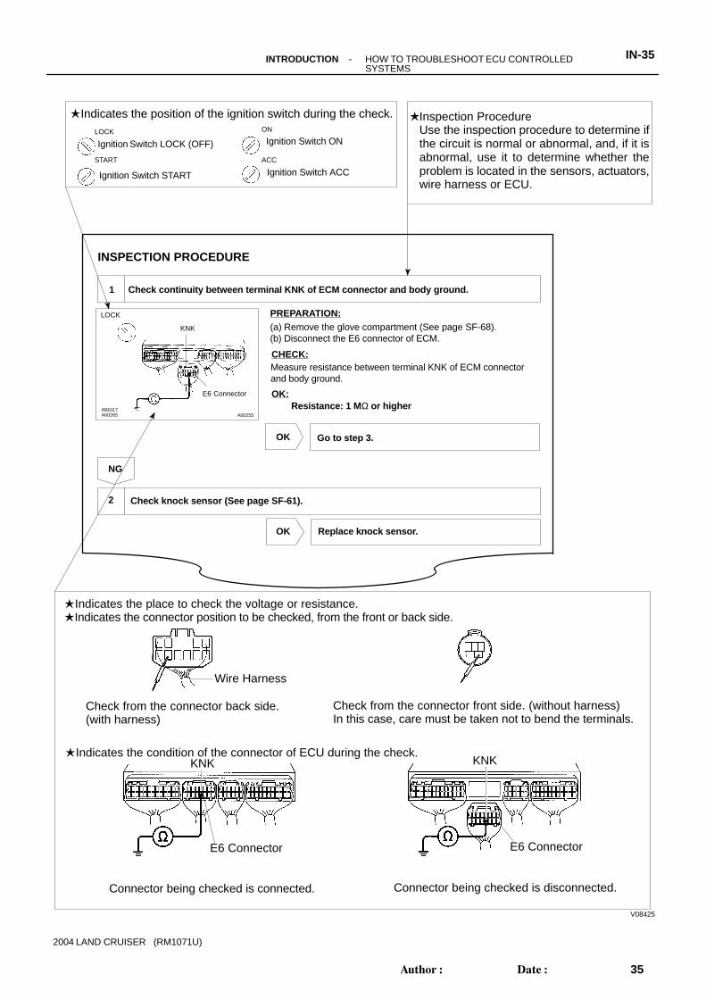
V08425
LOCK
KNK
E6 Connector
(a) Remove the glove compartment (See page SF-68).(b) Disconnect the E6 connector of ECM.
INSPECTION PROCEDURE
Replace knock sensor.
1 Check continuity between terminal KNK of ECM connector and body ground.
OK:
Check knock sensor (See page SF-61).
Measure resistance between terminal KNK of ECM connector and body ground.
Resistance: 1 M Ω or higher
Connector being checked is connected.
Indicates the condition of the connector of ECU during the check.
PREPARATION:
CHECK:
2
Go to step 3.
OK
OK
NG
Indicates the position of the ignition switch during the check.
Check from the connector back side.(with harness)
Ignition Switch LOCK (OFF)
Ignition Switch START
LOCKIgnition Switch ON
Ignition Switch ACCSTART
ON
ACC
Indicates the place to check the voltage or resistance. Indicates the connector position to be checked, from the front or back side.
Connector being checked is disconnected.
Check from the connector front side. (without harness)In this case, care must be taken not to bend the terminals.
E6 Connector
KNK
Wire Harness
E6 Connector
KNK
A00255AB0117A00265
Inspection ProcedureUse the inspection procedure to determine ifthe circuit is normal or abnormal, and, if it isabnormal, use it to determine whether theproblem is located in the sensors, actuators,wire harness or ECU.
-INTRODUCTION HOW TO TROUBLESHOOT ECU CONTROLLED SYSTEMS
IN-35
35Author: Date:
2004 LAND CRUISER (RM1071U)

FI0048
FI0047
FI0046
IN011-07
IN-36 -INTRODUCTION HOW TO TROUBLESHOOT ECU CONTROLLED SYSTEMS
36Author: Date:
2004 LAND CRUISER (RM1071U)
HOW TO USE THE DIAGNOSTICCHART AND INSPECTIONPROCEDURE1. CONNECTOR CONNECTION AND TERMINAL IN-
SPECTION For troubleshooting, diagnostic trouble code charts or
problem symptom table are provided for each circuit withdetailed inspection procedures on the following pages.
When all the component parts, wire harnesses and con-nectors of each circuit except the ECU are found to benormal in troubleshooting, then it is determined that theproblem is in the ECU. Accordingly, if diagnosis is per-formed without the problem symptoms occurring, refer toStep 8 to replace the ECU. So always confirm that theproblem symptoms are occurring, or proceed with inspec-tion while using the symptom simulation method.
The instructions ”Check wire harness and connector” and”Check and replace ECU” which appear in the inspectionprocedure, are common and applicable to all diagnostictrouble codes. Follow the procedure outlined belowwhenever these instructions appear.
OPEN CIRCUIT:This could be due to a disconnected wire harness, faulty con-tact in the connector, and a connector terminal pulled out, etc.HINT: It is rarely the case that a wire is broken in the middle of
it. Most cases occur at the connector. In particular, care-fully check the connectors of sensors and actuators
Faulty contact could be due to rusting of the connectorterminals, to foreign materials entering terminals or a de-formation of connector terminals. Simply disconnectingand reconnecting the connectors once changes thecondition of the connection and may result in a return tonormal operation. Therefore, in troubleshooting, if no ab-normality is found in the wire harness and connectorcheck, but the problem disappears after the check, thenthe cause is considered to be in the wire harness or con-nectors.
SHORT CIRCUIT:This could be due to a contact between wire harness and thebody ground or to a short circuit occurred inside the switch, etc.HINT:When there is a short circuit between the wire harness and bodyground, check thoroughly whether the wire harness is caughtin the body or is clamped properly.

FI7187
IN0379
Sensor SideECU Side
IN0378
Sensor Side
ECU Side
IN0380
Sensor Side
ECU Side
IN0381
Pull Lightly
Looseness of Crimping
-INTRODUCTION HOW TO TROUBLESHOOT ECU CONTROLLED SYSTEMS
IN-37
37Author: Date:
2004 LAND CRUISER (RM1071U)
2. CONNECTOR HANDLINGWhen inserting tester probes into a connector, insert them fromthe rear of the connector. When necessary, use mini test leads.For water resistant connectors which cannot be accessed frombehind, take good care not to deform the connector terminals.
3. CONTINUITY CHECK (OPEN CIRCUIT CHECK)(a) Disconnect the connectors at both ECU and sensor
sides.
(b) Measure the resistance between the applicable terminalsof the connectors.Resistance: 1 Ω or less
HINT:Measure the resistance while lightly shaking the wire harnessvertically and horizontally.
4. RESISTANCE CHECK (SHORT CIRCUIT CHECK)(a) Disconnect the connectors on both ends.(b) Measure the resistance between the applicable terminals
of the connectors and body ground. Be sure to carry outthis check on the connectors on both ends.Resistance: 1 M Ω or higher
HINT:Measure the resistance while lightly shaking the wire harnessvertically and horizontally.
5. VISUAL CHECK AND CONTACT PRESSURE CHECK(a) Disconnect the connectors at both ends.(b) Check for rust or foreign material, etc. in the terminals of
the connectors.(c) Check crimped portions for looseness or damage and
check that the terminals are secured in lock portion.HINT:The terminals should not come out when pulled lightly from theback.

Z17004
Fig. 1
OPEN
ECU
2
Sensor
2 2 211 1 1ABC
Z17005
Fig. 2
ECU
Sensor
21
ABC1 12 2
B04722
Fig. 3
ECU
Sensor
21
AB1C
1 12 2
12
B2
IN-38 -INTRODUCTION HOW TO TROUBLESHOOT ECU CONTROLLED SYSTEMS
38Author: Date:
2004 LAND CRUISER (RM1071U)
(d) Prepare a test male terminal and insert it in the female ter-minal, then pull it out.
NOTICE:When testing a gold-plated female terminal, always use agold-plated male terminal.HINT:When the test terminal is pulled out more easily than others,there may be poor contact in that section.
6. CHECK OPEN CIRCUITFor the open circuit in the wire harness in Fig. 1, perform ”(a)Continuity Check” or ”(b) Voltage Check” to locate the section.
(a) Check the continuity.(1) Disconnect connectors ”A” and ”C” and measure
the resistance between them.In the case of Fig. 2,Between terminal 1 of connector ”A” and terminal 1of connector ”C” → No continuity (open)Between terminal 2 of connector ”A” and terminal 2of connector ”C” → ContinuityTherefore, it is found out that there is an open circuitbetween terminal 1 of connector ”A” and terminal 1of connector ”C”.
(2) Disconnect connector ”B” and measure the resis-tance between the connectors.In the case of Fig. 3,Between terminal 1 of connector ”A” and terminal 1of connector ”B1” → ContinuityBetween terminal 1 of connector ”B2” and terminal1 of connector ”C” → No continuity (open)Therefore, it is found out that there is an open circuitbetween terminal 1 of connector ”B2” and terminal1 of connector ”C”.
Z17007
Fig. 4
Sensor
21
AC1 1
2 2
B 5V
5V
5V
0V
Z17008
Fig. 5
21
AC1 12 2
BSHORT
Z17009
Fig. 6
21
AC1 12 2
BSensor
ECU
-INTRODUCTION HOW TO TROUBLESHOOT ECU CONTROLLED SYSTEMS
IN-39
39Author: Date:
2004 LAND CRUISER (RM1071U)
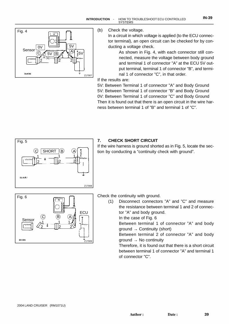
(b) Check the voltage.In a circuit in which voltage is applied (to the ECU connec-tor terminal), an open circuit can be checked for by con-ducting a voltage check.
As shown in Fig. 4, with each connector still con-nected, measure the voltage between body groundand terminal 1 of connector ”A” at the ECU 5V out-put terminal, terminal 1 of connector ”B”, and termi-nal 1 of connector ”C”, in that order.
If the results are:5V: Between Terminal 1 of connector ”A” and Body Ground5V: Between Terminal 1 of connector ”B” and Body Ground0V: Between Terminal 1 of connector ”C” and Body GroundThen it is found out that there is an open circuit in the wire har-ness between terminal 1 of ”B” and terminal 1 of ”C”.
7. CHECK SHORT CIRCUITIf the wire harness is ground shorted as in Fig. 5, locate the sec-tion by conducting a ”continuity check with ground”.
Check the continuity with ground.(1) Disconnect connectors ”A” and ”C” and measure
the resistance between terminal 1 and 2 of connec-tor ”A” and body ground.In the case of Fig. 6Between terminal 1 of connector ”A” and bodyground → Continuity (short)Between terminal 2 of connector ”A” and bodyground → No continuityTherefore, it is found out that there is a short circuitbetween terminal 1 of connector ”A” and terminal 1of connector ”C”.
Z17808
Fig. 7
Sensor
21
AB1C1 12 2
12
B2ECU
IN0383
Example
Ground
IN0384
Ground
Ground
ECU Side
W/H Side
IN-40 -INTRODUCTION HOW TO TROUBLESHOOT ECU CONTROLLED SYSTEMS
40Author: Date:
2004 LAND CRUISER (RM1071U)
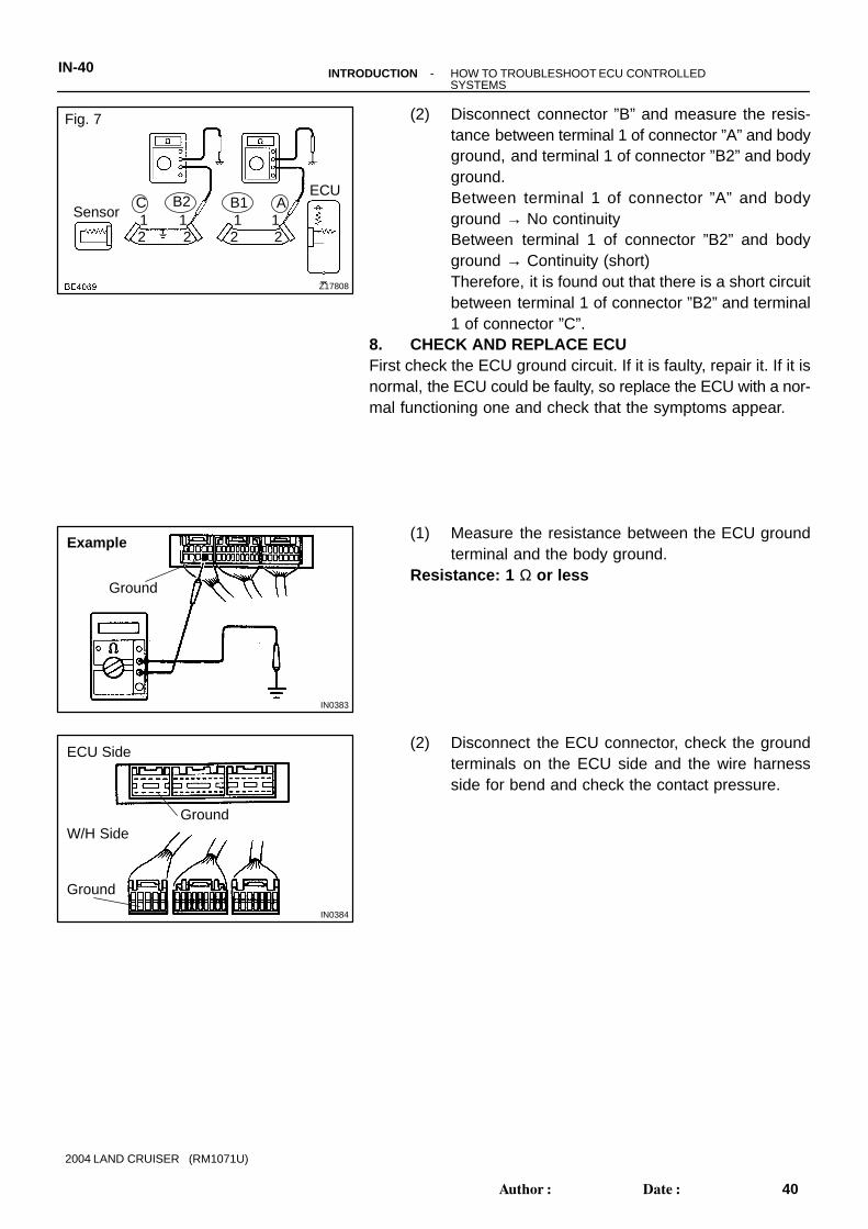
(2) Disconnect connector ”B” and measure the resis-tance between terminal 1 of connector ”A” and bodyground, and terminal 1 of connector ”B2” and bodyground.Between terminal 1 of connector ”A” and bodyground → No continuityBetween terminal 1 of connector ”B2” and bodyground → Continuity (short)Therefore, it is found out that there is a short circuitbetween terminal 1 of connector ”B2” and terminal1 of connector ”C”.
8. CHECK AND REPLACE ECUFirst check the ECU ground circuit. If it is faulty, repair it. If it isnormal, the ECU could be faulty, so replace the ECU with a nor-mal functioning one and check that the symptoms appear.
(1) Measure the resistance between the ECU groundterminal and the body ground.
Resistance: 1 Ω or less
(2) Disconnect the ECU connector, check the groundterminals on the ECU side and the wire harnessside for bend and check the contact pressure.

IN00U-13
N17080
Filler Cap
Float
Reservoir Tank
Grommet
Clip
Slotted Spring Pin
: Specified torque
Non-reusable part
Cylinder
PistonPush Rod
WasherSnap Ring
Boot
Gasket
Lock Nut
Clevis Pin
Clevis
N·m (kgf·cm, ft·lbf)
12 (120, 9)
15 (155, 11)
-INTRODUCTION HOW TO USE THIS MANUALIN-1
1Author: Date:
2004 LAND CRUISER (RM1071U)
HOW TO USE THIS MANUALGENERAL INFORMATION1. INDEXAn INDEX is provided on the first page of each section to guide you to the item to be repaired. To assist youin finding your way through the manual, the Section Title and major heading are given at the top of everypage.2. GENERAL DESCRIPTIONAt the beginning of each section, a General Description is given that pertains to all repair operations con-tained in that section.Read these precautions before starting any repair task.3. TROUBLESHOOTINGTROUBLESHOOTING tables are included for each system to help you diagnose the problem and find thecause. The fundamentals of how to proceed with troubleshooting are described on page IN-26 .Be sure to read this before performing troubleshooting.4. PREPARATIONPreparation lists the SST (Special Service Tools), recommended tools, equipment, lubricant and SSM (Spe-cial Service Materials) which should be prepared before beginning the operation and explains the purposeof each one.5. REPAIR PROCEDURESMost repair operations begin with an overview illustration. It identifies the components and shows how theparts fit together.Example:

Illustration:what to do and where
21. CHECK PISTON STROKE OF OVERDRIVE BRAKE
(a)
Task heading : what to do
SST 09350-30020 (09350-06120)
Set part No. Component part No.Detailed text : how to do task
(b)
Piston stroke: 1.40 1.70 mm (0.0551 0.0669 in.)
Specification
Place SST and a dial indicator onto the overdrive brake pis-ton as shown in the illustration.
Measure the stroke applying and releasing the compressedair (392 785 kPa, 4 8 kgf/cm2 or 57 114 psi) as shownin the illustration.
IN-2-INTRODUCTION HOW TO USE THIS MANUAL
2Author: Date:
2004 LAND CRUISER (RM1071U)
The procedures are presented in a step-by-step format: The illustration shows what to do and where to do it. The task heading tells what to do. The detailed text tells how to perform the task and gives other information such as specifications
and warnings.Example:
This format provides the experienced technician with a FAST TRACK to the information needed. The uppercase task heading can be read at a glance when necessary, and the text below it provides detailed informa-tion. Important specifications and warnings always stand out in bold type.6. REFERENCESReferences have been kept to a minimum. However, when they are required you are given the page to referto.7. SPECIFICATIONSSpecifications are presented in bold type throughout the text where needed. You never have to leave theprocedure to look up your specifications. They are also found in Service Specifications section for quick ref-erence.8. CAUTIONS, NOTICES, HINTS: CAUTIONS are presented in bold type, and indicate there is a possibility of injury to you or other
people. NOTICES are also presented in bold type, and indicate the possibility of damage to the components
being repaired. HINTS are separated from the text but do not appear in bold. They provide additional information to
help you perform the repair efficiently.9. SI UNITThe UNITS given in this manual are primarily expressed according to the SI UNIT (International System ofUnit), and alternately expressed in the metric system and in the English System.Example:
Torque: 30 N·m (310 kgf·cm, 22 ft·lbf)

IN04P-02
B04197
A
B
B04198
2UZ-FE Engine:
-INTRODUCTION IDENTIFICATION INFORMATIONIN-3
3Author: Date:
2004 LAND CRUISER (RM1071U)
IDENTIFICATION INFORMATIONVEHICLE IDENTIFICATION ANDENGINE SERIAL NUMBER
1. VEHICLE IDENTIFICATION NUMBERThe vehicle identification number is stamped on the vehicleidentification number plate and the certification label, as shownin the illustration.
A: Vehicle Identification Number PlateB: Certification Label
2. ENGINE SERIAL NUMBERThe engine serial number is stamped on the engine block, asshown in the illustration.

FI1066
IN07M-02
Z11554
Seal Lock Adhesive
IN-4-INTRODUCTION REPAIR INSTRUCTIONS
4Author: Date:
2004 LAND CRUISER (RM1071U)
REPAIR INSTRUCTIONSGENERAL INFORMATIONBASIC REPAIR HINT(a) Use fender, seat and floor covers to keep the vehicle
clean and prevent damage.(b) During disassembly, keep parts in the appropriate order
to facilitate reassembly.(c) Installation and removal of battery terminal:
(1) Before performing electrical work, disconnect thenegative (-) terminal cable from the battery.
(2) If it is necessary to disconnect the battery for in-spection or repair, first disconnect the negative (-)terminal cable.
(3) When disconnecting the terminal cable to preventdamage to battery terminal, loosen the cable nutand raise the cable straight up without twisting orprying it.
(4) Clean the battery terminals and cable ends with aclean shop rag. Do not scrape them with a file or oth-er abrasive objects.
(5) Install the cable ends to the battery terminals afterloosening the nut, and tighten the nut after installa-tion. Do not use a hammer to tap the cable endsonto the terminals.
(6) Be sure the cover for the positive (+) terminal isproperly in place.
(d) Check hose and wiring connectors to make sure that theyare connected securely and correctly.
(e) Non-reusable parts(1) Always replace cotter pins, gaskets, O-rings and oil
seals, etc. with new ones.(2) Non-reusable parts are indicated in the component
illustrations by the ”” symbol.
(f) Precoated partsPrecoated parts are bolts and nuts, etc. that are coatedwith a seal lock adhesive at the factory.(1) If a precoated part is retightened, loosened or
caused to move in any way, it must be recoated withthe specified adhesive.
(2) When reusing precoated parts, clean off the oldadhesive and dry with compressed air. Then applythe specified seal lock adhesive to the bolt, nut orthreads.

BE1367
Medium Current Fuse and High Current FuseEqual Amperage Rating
V00076
AbbreviationPart NameSymbolIllustration
FUSE
MEDIUM CURRENT FUSE
HIGH CURRENT FUSE
FUSIBLE LINK
CIRCUIT BREAKER
FUSE
M-FUSE
H-FUSE
FL
CB
-INTRODUCTION REPAIR INSTRUCTIONSIN-5
5Author: Date:
2004 LAND CRUISER (RM1071U)
(3) Precoated parts are indicated in the component il-lustrations by the ”” symbol.
(g) When necessary, use a sealer on gaskets to preventleaks.
(h) Carefully observe all specifications for bolt tighteningtorques. Always use a torque wrench.
(i) Use of special service tools (SST) and special service ma-terials (SSM) may be required, depending on the natureof the repair. Be sure to use SST and SSM where speci-fied and follow the proper work procedure. A list of SSTand SSM can be found in Preparation section in thismanual.
(j) When replacing fuses, be sure the new fuse has the cor-rect amperage rating. DO NOT exceed the rating or useone with a lower rating.

IN0253
WRONG CORRECT
IN0252
WRONG CORRECT
IN-6-INTRODUCTION REPAIR INSTRUCTIONS
6Author: Date:
2004 LAND CRUISER (RM1071U)
(k) Care must be taken when jacking up and supporting thevehicle. Be sure to lift and support the vehicle at the prop-er locations (See page IN-8 ). Cancel the parking brake on the level place and
shift the transmission in N position. When jacking up the front wheels of the vehicle at
first place stoppers behind the rear wheels. When jacking up the rear wheels of the vehicle at
first place stoppers before the front wheels. When either the front or rear wheels only should be
jacked up, set rigid racks and place stoppers in frontand behind the other wheels on the ground.
After the vehicle is jacked up, be sure to support iton rigid racks. It is extremely dangerous to do anywork on a vehicle raised on a jack alone, even fora small job that can be finished quickly.
(l) Observe the following precautions to avoid damage to thefollowing parts:(1) Do not open the cover or case of the ECU unless
absolutely necessary. (If the IC terminals aretouched, the IC may be destroyed by static electric-ity.)
(2) To disconnect vacuum hoses, pull off the end, notthe middle of the hose.
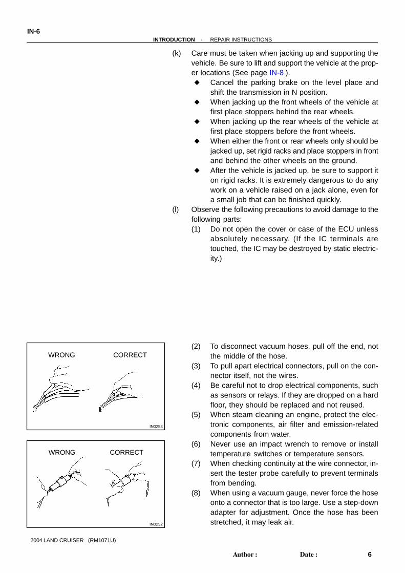
(3) To pull apart electrical connectors, pull on the con-nector itself, not the wires.
(4) Be careful not to drop electrical components, suchas sensors or relays. If they are dropped on a hardfloor, they should be replaced and not reused.
(5) When steam cleaning an engine, protect the elec-tronic components, air filter and emission-relatedcomponents from water.
(6) Never use an impact wrench to remove or installtemperature switches or temperature sensors.
(7) When checking continuity at the wire connector, in-sert the tester probe carefully to prevent terminalsfrom bending.
(8) When using a vacuum gauge, never force the hoseonto a connector that is too large. Use a step-downadapter for adjustment. Once the hose has beenstretched, it may leak air.

IN0002
Example
-INTRODUCTION REPAIR INSTRUCTIONSIN-7
7Author: Date:
2004 LAND CRUISER (RM1071U)
(m) Installation and removal of vacuum hose:(1) When disconnecting vacuum hoses, use tags to
identify how they should be reconnected to.(2) After completing a job, double check that the vacu-
um hoses are properly connected. A label under thehood shows the proper layout.
(n) Bleeding of hydraulic brake booster systemWhen repairing the hydraulic brake booster or ABS,bleeding the air out of the hydraulic brake booster(See page BR-4 ).
(o) Unless otherwise stated, all resistance is measured at anambient temperature of 20°C (68°F). Because the resis-tance may be outside specifications if measured at hightemperatures immediately after the vehicle has been run-ning, measurement should be made when the engine hascooled down.

IN04O-02
B04208
SUPPORT POSITION
Front
Rear
Engine under cover
Rear differential carrier
CAUTION : When jacking-up the front and rear, make sure the car isnot carrying any extra weight.
Safety stand
FRONT
JACK POSITION
SCREW TYPE JACK POSITION
IN-8-INTRODUCTION REPAIR INSTRUCTIONS
8Author: Date:
2004 LAND CRUISER (RM1071U)
VEHICLE LIFT AND SUPPORT LOCATIONS

B04209
SWING ARM TYPE LIFT
NOTICE: When lifting the vehicle, place the supports correctlyat the positions shown above.
PLATE TYPE LIFT (DO NOT USE.)
Never use the plate type lift-using it to lift up the vehicle willcause the body shape to warp.
NOTICE:
FRONT
FRONT
-INTRODUCTION REPAIR INSTRUCTIONSIN-9
9Author: Date:
2004 LAND CRUISER (RM1071U)

FI1066
IN07M-02
Z11554
Seal Lock Adhesive
IN-4-INTRODUCTION REPAIR INSTRUCTIONS
4Author: Date:
2004 LAND CRUISER (RM1071U)
REPAIR INSTRUCTIONSGENERAL INFORMATIONBASIC REPAIR HINT(a) Use fender, seat and floor covers to keep the vehicle
clean and prevent damage.(b) During disassembly, keep parts in the appropriate order
to facilitate reassembly.(c) Installation and removal of battery terminal:
(1) Before performing electrical work, disconnect thenegative (-) terminal cable from the battery.
(2) If it is necessary to disconnect the battery for in-spection or repair, first disconnect the negative (-)terminal cable.
(3) When disconnecting the terminal cable to preventdamage to battery terminal, loosen the cable nutand raise the cable straight up without twisting orprying it.
(4) Clean the battery terminals and cable ends with aclean shop rag. Do not scrape them with a file or oth-er abrasive objects.
(5) Install the cable ends to the battery terminals afterloosening the nut, and tighten the nut after installa-tion. Do not use a hammer to tap the cable endsonto the terminals.
(6) Be sure the cover for the positive (+) terminal isproperly in place.
(d) Check hose and wiring connectors to make sure that theyare connected securely and correctly.
(e) Non-reusable parts(1) Always replace cotter pins, gaskets, O-rings and oil
seals, etc. with new ones.(2) Non-reusable parts are indicated in the component
illustrations by the ”” symbol.
(f) Precoated partsPrecoated parts are bolts and nuts, etc. that are coatedwith a seal lock adhesive at the factory.(1) If a precoated part is retightened, loosened or
caused to move in any way, it must be recoated withthe specified adhesive.
(2) When reusing precoated parts, clean off the oldadhesive and dry with compressed air. Then applythe specified seal lock adhesive to the bolt, nut orthreads.

BE1367
Medium Current Fuse and High Current FuseEqual Amperage Rating
V00076
AbbreviationPart NameSymbolIllustration
FUSE
MEDIUM CURRENT FUSE
HIGH CURRENT FUSE
FUSIBLE LINK
CIRCUIT BREAKER
FUSE
M-FUSE
H-FUSE
FL
CB
-INTRODUCTION REPAIR INSTRUCTIONSIN-5
5Author: Date:
2004 LAND CRUISER (RM1071U)
(3) Precoated parts are indicated in the component il-lustrations by the ”” symbol.
(g) When necessary, use a sealer on gaskets to preventleaks.
(h) Carefully observe all specifications for bolt tighteningtorques. Always use a torque wrench.
(i) Use of special service tools (SST) and special service ma-terials (SSM) may be required, depending on the natureof the repair. Be sure to use SST and SSM where speci-fied and follow the proper work procedure. A list of SSTand SSM can be found in Preparation section in thismanual.
(j) When replacing fuses, be sure the new fuse has the cor-rect amperage rating. DO NOT exceed the rating or useone with a lower rating.
IN0253
WRONG CORRECT
IN0252
WRONG CORRECT
IN-6-INTRODUCTION REPAIR INSTRUCTIONS
6Author: Date:
2004 LAND CRUISER (RM1071U)
(k) Care must be taken when jacking up and supporting thevehicle. Be sure to lift and support the vehicle at the prop-er locations (See page IN-8 ). Cancel the parking brake on the level place and
shift the transmission in N position. When jacking up the front wheels of the vehicle at
first place stoppers behind the rear wheels. When jacking up the rear wheels of the vehicle at
first place stoppers before the front wheels. When either the front or rear wheels only should be
jacked up, set rigid racks and place stoppers in frontand behind the other wheels on the ground.
After the vehicle is jacked up, be sure to support iton rigid racks. It is extremely dangerous to do anywork on a vehicle raised on a jack alone, even fora small job that can be finished quickly.
(l) Observe the following precautions to avoid damage to thefollowing parts:(1) Do not open the cover or case of the ECU unless
absolutely necessary. (If the IC terminals aretouched, the IC may be destroyed by static electric-ity.)
(2) To disconnect vacuum hoses, pull off the end, notthe middle of the hose.
(3) To pull apart electrical connectors, pull on the con-nector itself, not the wires.
(4) Be careful not to drop electrical components, suchas sensors or relays. If they are dropped on a hardfloor, they should be replaced and not reused.
(5) When steam cleaning an engine, protect the elec-tronic components, air filter and emission-relatedcomponents from water.
(6) Never use an impact wrench to remove or installtemperature switches or temperature sensors.
(7) When checking continuity at the wire connector, in-sert the tester probe carefully to prevent terminalsfrom bending.
(8) When using a vacuum gauge, never force the hoseonto a connector that is too large. Use a step-downadapter for adjustment. Once the hose has beenstretched, it may leak air.

IN0002
Example
-INTRODUCTION REPAIR INSTRUCTIONSIN-7
7Author: Date:
2004 LAND CRUISER (RM1071U)
(m) Installation and removal of vacuum hose:(1) When disconnecting vacuum hoses, use tags to
identify how they should be reconnected to.(2) After completing a job, double check that the vacu-
um hoses are properly connected. A label under thehood shows the proper layout.
(n) Bleeding of hydraulic brake booster systemWhen repairing the hydraulic brake booster or ABS,bleeding the air out of the hydraulic brake booster(See page BR-4 ).
(o) Unless otherwise stated, all resistance is measured at anambient temperature of 20°C (68°F). Because the resis-tance may be outside specifications if measured at hightemperatures immediately after the vehicle has been run-ning, measurement should be made when the engine hascooled down.

IN04O-02
B04208
SUPPORT POSITION
Front
Rear
Engine under cover
Rear differential carrier
CAUTION : When jacking-up the front and rear, make sure the car isnot carrying any extra weight.
Safety stand
FRONT
JACK POSITION
SCREW TYPE JACK POSITION
IN-8-INTRODUCTION REPAIR INSTRUCTIONS
8Author: Date:
2004 LAND CRUISER (RM1071U)
VEHICLE LIFT AND SUPPORT LOCATIONS

B04209
SWING ARM TYPE LIFT
NOTICE: When lifting the vehicle, place the supports correctlyat the positions shown above.
PLATE TYPE LIFT (DO NOT USE.)
Never use the plate type lift-using it to lift up the vehicle willcause the body shape to warp.
NOTICE:
FRONT
FRONT
-INTRODUCTION REPAIR INSTRUCTIONSIN-9
9Author: Date:
2004 LAND CRUISER (RM1071U)