Embed Size (px)
Citation preview
1
The Unofficial guide for those who are COMPLETELY Lost...
1) Intro toSketchyPhysics
2) Basics
3) Setting the state
4) Shape Physics
5) Advanced ShapePhysics
6) Grouping groups
7) Jointing Basics
8) Using the UI forAdvanced Jointing
9) More onAdvanced Jointing
10) When things gowrong
Intro to SketchyPhysics
What is SketchyPhysics and How Can I Get It?
Sketchyphysics is a plugin written by C. Phillips for Google's 3-D programSketchup. It allows the objects you draw in Sketchup to "come to life" in a realworld simulation with gravity, collisions and interactions with other objects.
If you want to install it, you must first have the latest version of Sketchupinstalled. (It is free.) Then do download SketchyPhysics and install it.
It is an amazing addition to Sketchup, but finding any help, even a simplestarters guide is next to impossible.
If you've seen the You-Tube video of even the simple car rolling down a hill andthen tried to make it, you'll see exactly how frustrating SP can be when wheelsfloat in the air, the body falls off, or the damn thing just won't move!
My goal of these few humble pages is to provide a starting point so anyone whoknows Sketchup can start experimenting with the physics.
This isn't going to be a comprehensive help site, but rather a diving board so youcan start the learning process on your own. This also won't be a Sketchup guide.I assume you are already proficient in Sketchup before starting here.
If you need more information than you can find in this guide, stop on by theSketchyPhysics Forum that is a part of the SketchUp Community Forums.

2
The Basics...
The first thing to note is that SketchyPhysics ONLY WORKS WITH GROUPED OBJECTS.
If you start by making a cube and grouping all the parts into one object, the object will be recognizedby SP. Physics will then be applied when you press the RUN button.
There are also auto-shapes provided through a toolbar that is installed with SketchyPhysics. Theseshapes are already grouped and ready to use, all you have to do is draw them where you want to inyour model.
Setting the STATE of the Object
After making a grouped object, there are 2 main attributes to use when creating an object to use in SP.They are accessed by Right-Clicking a grouped object.

3
The first option is STATE. This sets how the object behaves in SP.
The STATE options are:
FROZEN: Image will stay in place (it won't fall) until it is hit by another object, then regular Physicstakes over.
STATIC: The object will NEVER move, no matter what happens to it. Other objects will bounceoff of it.
IGNORE: The object will not move, and other objects will not interact with it. They will passthrough it. (It is a ghost.)
On the next page we'll discuss the second option: Shape.
Continue on to SHAPES.
4
Shape Physics
The other two right-menu options are SHAPE and DEBUG, and they are used together.
SHAPE: Sets the shape that SP sees the group as.
Just because you grouped a Cube doesn't mean SP "sees" it as a Cube!
USE THE SHAPE OPTION ON EVERY OBJECT YOU CREATE FOR SP!!!!
DEBUG: Use this option to check the shape SP "sees". After grouping an object and setting its SPshape, select this option and press RUN. SP will make a black wire diagram of the object AS IT SEESIT.
You may be surprised at what it sees. Also, just because you make a cylinder and set the shape tocylinder, doesn't mean it will be oriented correctly. (See below.)
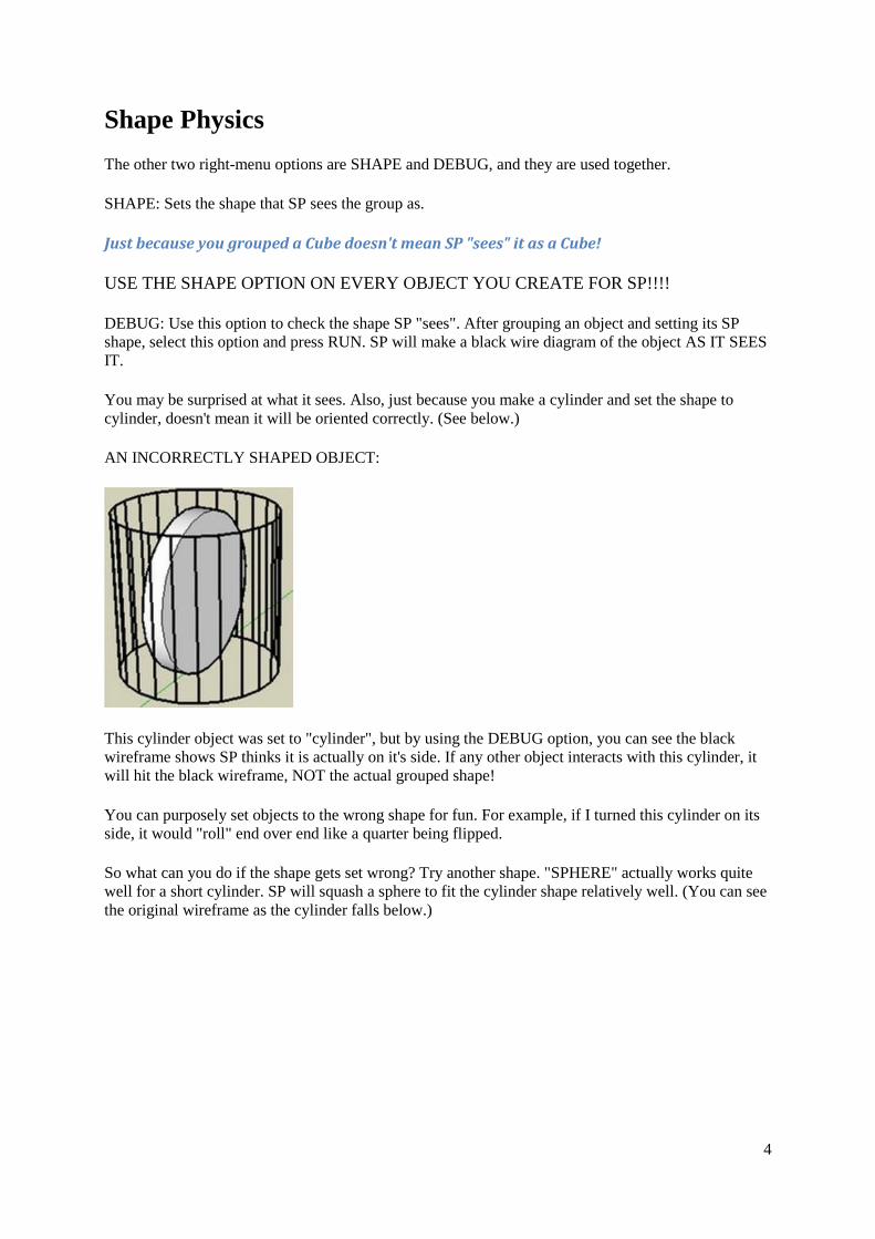
AN INCORRECTLY SHAPED OBJECT:
This cylinder object was set to "cylinder", but by using the DEBUG option, you can see the blackwireframe shows SP thinks it is actually on it's side. If any other object interacts with this cylinder, itwill hit the black wireframe, NOT the actual grouped shape!
You can purposely set objects to the wrong shape for fun. For example, if I turned this cylinder on itsside, it would "roll" end over end like a quarter being flipped.
So what can you do if the shape gets set wrong? Try another shape. "SPHERE" actually works quitewell for a short cylinder. SP will squash a sphere to fit the cylinder shape relatively well. (You can seethe original wireframe as the cylinder falls below.)

5
Advanced shape physics
There are a few more shapes that are provided for you when the normal ones don't work out.
The first one to note is "STATIC MESH". This draws a mesh around your shape to create theoutlines. This is beneficial when making a "hill" for something to roll down, or a multi-pitched slope.However, it is STATIC and UN-MOVEABLE. Therefore this option is mostly used when making a"ground plane" for everything else to "ride" on.
This ramp was made as a "STATIC MESH".
It does not move, however the ball will fall and roll down its slope.
6
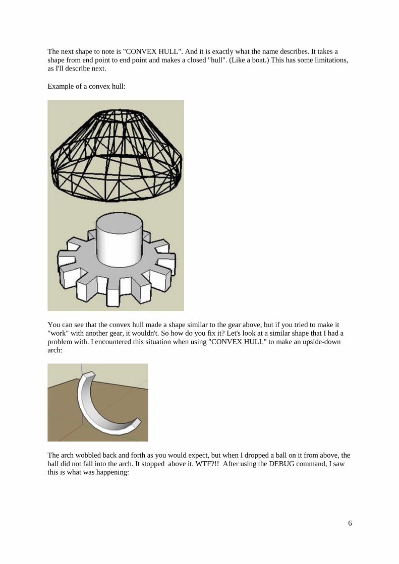
The next shape to note is "CONVEX HULL". And it is exactly what the name describes. It takes ashape from end point to end point and makes a closed "hull". (Like a boat.) This has some limitations,as I'll describe next.
Example of a convex hull:
You can see that the convex hull made a shape similar to the gear above, but if you tried to make it"work" with another gear, it wouldn't. So how do you fix it? Let's look at a similar shape that I had aproblem with. I encountered this situation when using "CONVEX HULL" to make an upside-downarch:
The arch wobbled back and forth as you would expect, but when I dropped a ball on it from above, theball did not fall into the arch. It stopped above it. WTF?!! After using the DEBUG command, I sawthis is what was happening:
7
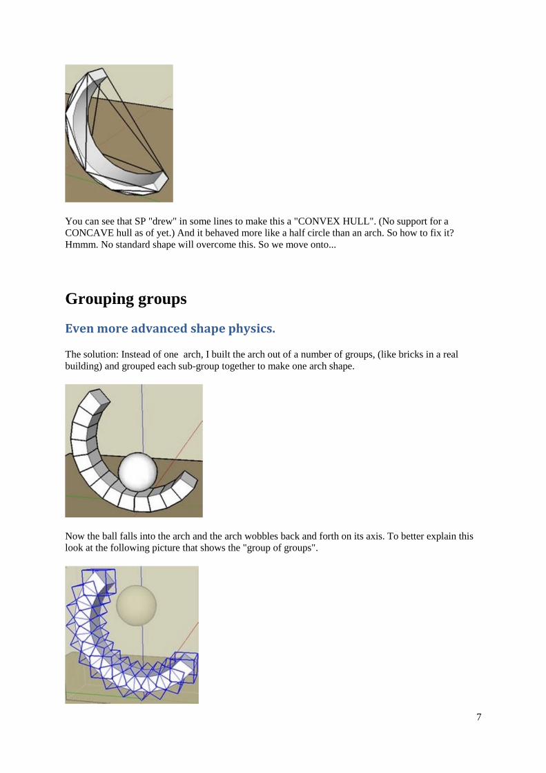
You can see that SP "drew" in some lines to make this a "CONVEX HULL". (No support for aCONCAVE hull as of yet.) And it behaved more like a half circle than an arch. So how to fix it?Hmmm. No standard shape will overcome this. So we move onto...
Grouping groups
Even more advanced shape physics.
The solution: Instead of one arch, I built the arch out of a number of groups, (like bricks in a realbuilding) and grouped each sub-group together to make one arch shape.
Now the ball falls into the arch and the arch wobbles back and forth on its axis. To better explain thislook at the following picture that shows the "group of groups".
8
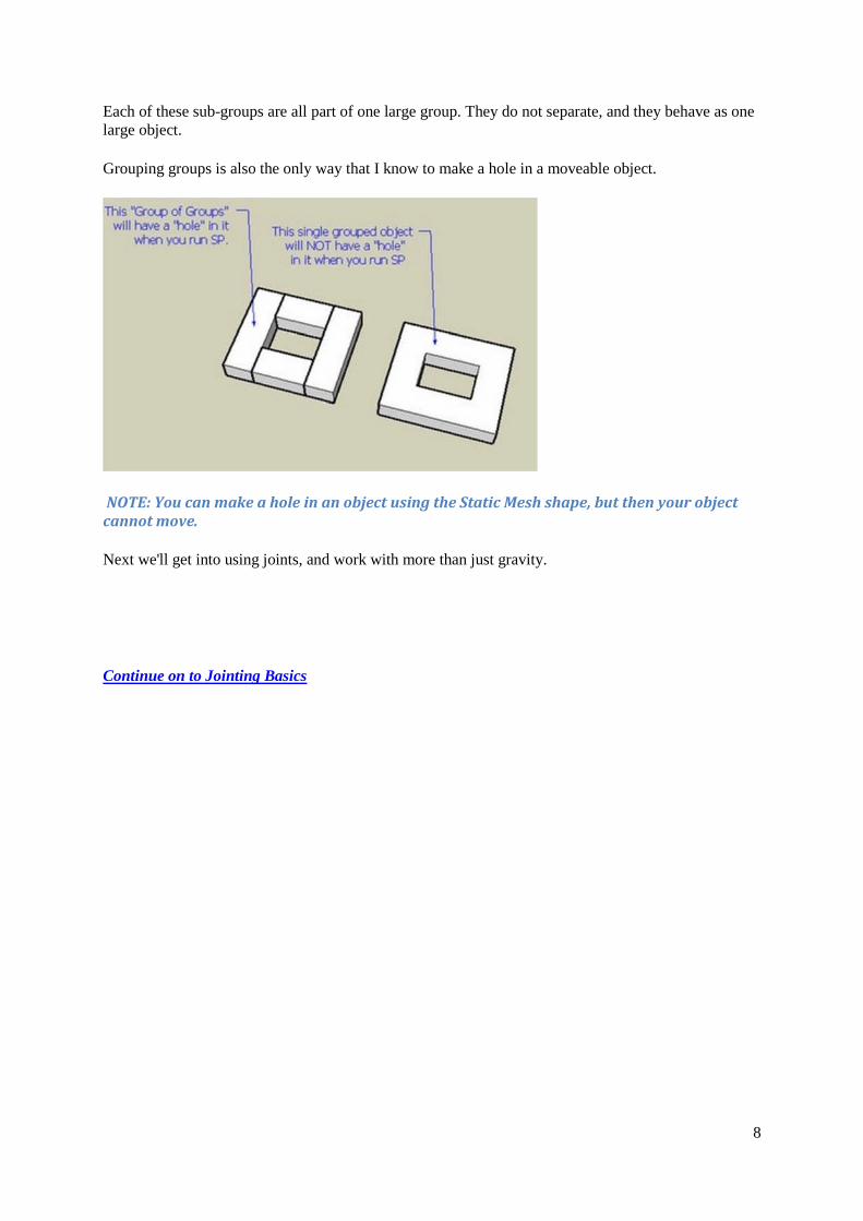
Each of these sub-groups are all part of one large group. They do not separate, and they behave as onelarge object.
Grouping groups is also the only way that I know to make a hole in a moveable object.
NOTE: You can make a hole in an object using the Static Mesh shape, but then your objectcannot move.
Next we'll get into using joints, and work with more than just gravity.
Continue on to Jointing Basics

9
Jointing Basics
Up until now, we have only made objects that will be affected by gravity and collisions in SP. Nowwe'll learn how to use joints to make automated or specific movement in our models.
A joint is a special type of grouped object that can "control" other objects in SP.
There are a number of different joints you can choose to add to your model, and each joint has aspecific behavior.
The joints also have their own special tool for defining their connections, the Joint Connector tool:
There are three basic steps when adding a joint to a model:
Add a joint for the part you want to make move.
Make the moveable part and the joint a group.
Joint-connect the joint to a “parent” object in the model.
These 3 steps will work for MOST joints in MOST situations.
Before we get started, let’s be clear on the terminology I’ll be using throughout this guide.
JOINT-CONNECTING an object to its joint means using the Joint-Connector tool.
GROUPING an object to its joint means making them a group like any other group in Sketchup.
One of the harder concepts for me to grasp when first working with SP was when to joint-connect anobject to a joint, or when to group it with a joint. Thanks to C. Phillips, I now have a betterunderstanding of when to do which.
With that being said, let’s move on to an example, and build a car that rolls. If you want to followalong with this tutorial, you can download the basic model HERE.
NOTE: The model just contains the primitive shapes. To make it work, you'll have to follow thistutorial and put it together.
The first thing we'll want to do is make a simple body and group it.

10
Next we'll make a wheel shape and group it.
Set the shape of the wheel to "convex-hull" or "sphere" and make 3 copies of it:
(Click any picture below to enlarge)
Now is a good time to Debug the wheels and body to make sure they are shaped properly.
Next move the wheels to where you want them to be on the body. It is easier to move the wheels ifthey have a design with some sort of center point. (This is why I made them in 4 sections instead ofone solid circle.)
11
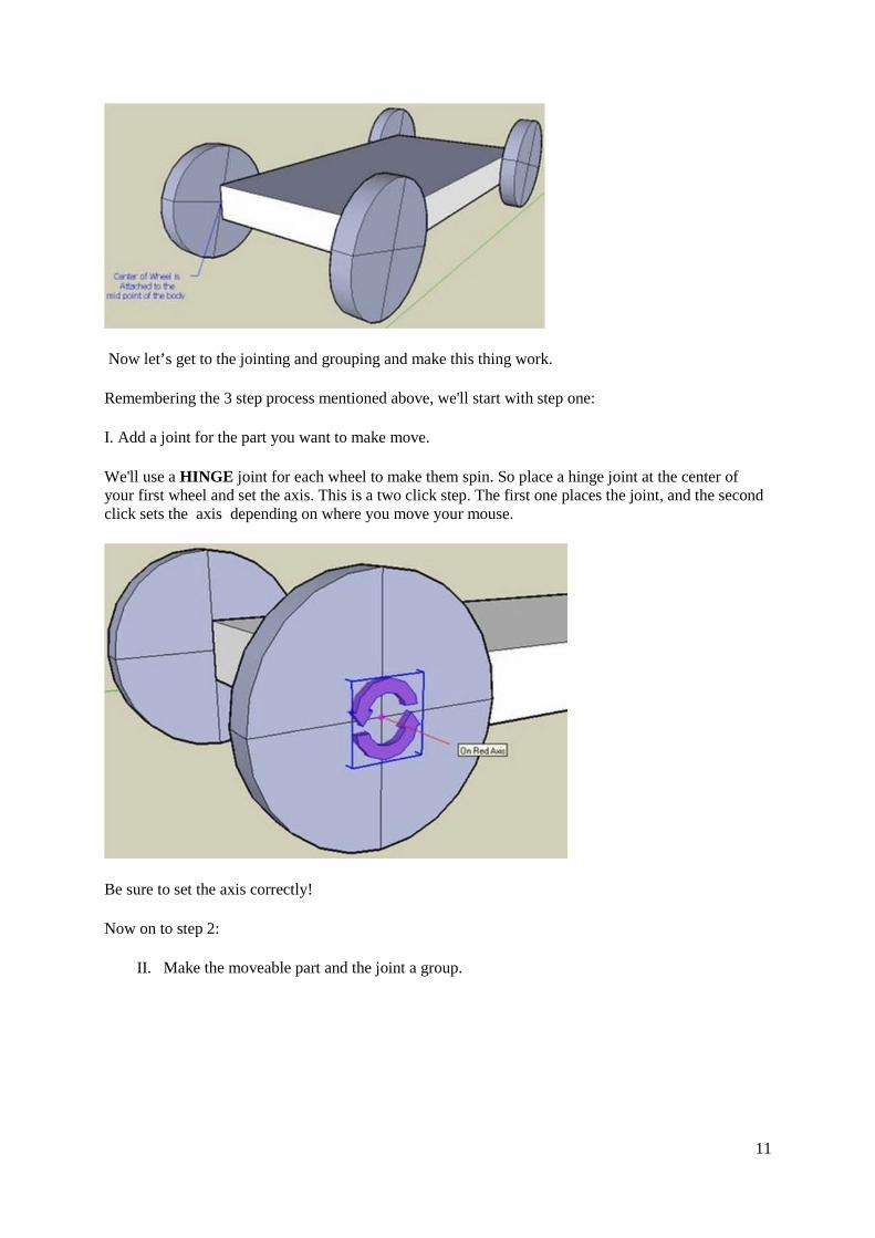
Now let’s get to the jointing and grouping and make this thing work.
Remembering the 3 step process mentioned above, we'll start with step one:
I. Add a joint for the part you want to make move.
We'll use a HINGE joint for each wheel to make them spin. So place a hinge joint at the center ofyour first wheel and set the axis. This is a two click step. The first one places the joint, and the secondclick sets the axis depending on where you move your mouse.
Be sure to set the axis correctly!
Now on to step 2:
II. Make the moveable part and the joint a group.
12
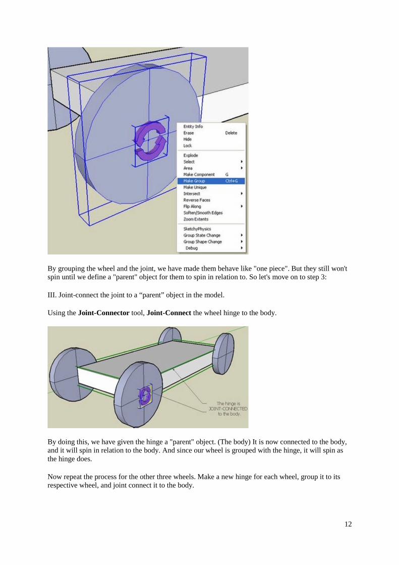
By grouping the wheel and the joint, we have made them behave like "one piece". But they still won'tspin until we define a "parent" object for them to spin in relation to. So let's move on to step 3:
III. Joint-connect the joint to a “parent” object in the model.
Using the Joint-Connector tool, Joint-Connect the wheel hinge to the body.
By doing this, we have given the hinge a "parent" object. (The body) It is now connected to the body,and it will spin in relation to the body. And since our wheel is grouped with the hinge, it will spin asthe hinge does.
Now repeat the process for the other three wheels. Make a new hinge for each wheel, group it to itsrespective wheel, and joint connect it to the body.

13
This brings up another point to be made when working with joints. I have found that copying jointsleads to unexpected results, so don't copy the hinge for the other three wheels. Be sure to make a newhinge for each wheel.
So As a rule of thumb: Don’t copy joints.
In the end, you should have all four hinges joint-connected to the body, making it a parent to all thehinges. And since the wheels are grouped to their hinges, the entire model will behave as one bigfamily.
It's now time to test our car. If we RUN the animation now, the entire car would fall into space as oneobject. So let's make a ground plane for the car to rest on. You can either make a ground planeyourself and set it to "STATIC MESH" or you can use the auto-shape (SOLID FLOOR) to make theplane in one click.
14
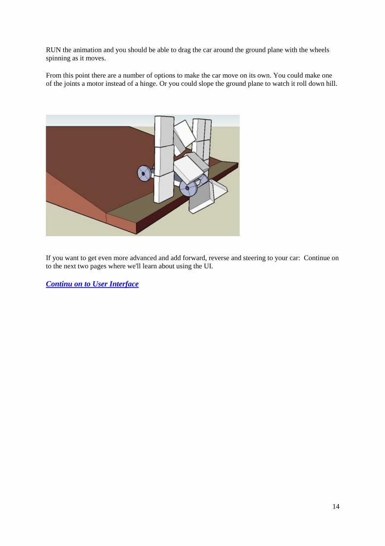
RUN the animation and you should be able to drag the car around the ground plane with the wheelsspinning as it moves.
From this point there are a number of options to make the car move on its own. You could make oneof the joints a motor instead of a hinge. Or you could slope the ground plane to watch it roll down hill.
If you want to get even more advanced and add forward, reverse and steering to your car: Continue onto the next two pages where we'll learn about using the UI.
Continu on to User Interface

15
The Inspector window
Now that we have the basics of using SP down, let's move on to some of the more advanced featuresavailable.
One of the first things you notice after installing SP is the SketchyPhysics Inspector window(otherwise known as the UI) that pops up whenever you start SU.
The UI contains information and adjustable settings related to the object selected in yourmodel. Anytime you select an object in your model, this window shows the general properties of thatobject. This is particularly useful when checking joint properties.
Let's take a look at the bottom of the UI first. You'll see there are a series of check-boxes under theSTATE header:
You can set the state of the object here just like you do by right-clicking the object.
One important difference is the showcollision check box. This is similiar to the "debug" commandwhen right-clicking, except instead of drawing a wire-mesh only in the initial position of the object,
16
the wire mesh is visible throughout the objects movement. Now you can see when and how objectscollide, not just how they look when they start.
Further up in the UI, you will see numerous settings for joints such as: min, max, accel, damp andcontroller. Select a joint first, and then use these settings to add further control to your selected joint.
Note that these options depend on what type of a joint is selected. Some, all, or none of theseoptions may be available depending on the joint type.
To see how powerful the UI can be, lets start with a simple Hinge joint and see what kind ofmodifications we can do to it through the UI. Through the UI, we can make a simple hinge behavelike a servo, or even a customized motor with forward and reverse capabilities!
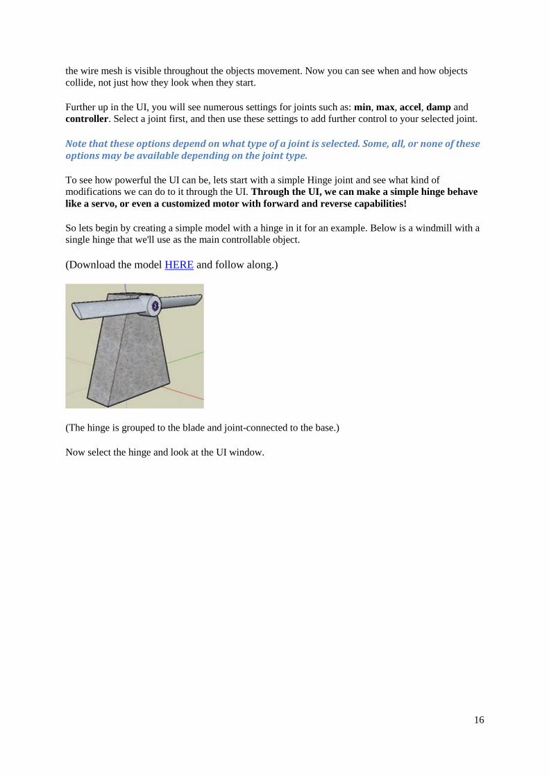
So lets begin by creating a simple model with a hinge in it for an example. Below is a windmill with asingle hinge that we'll use as the main controllable object.
(Download the model HERE and follow along.)
(The hinge is grouped to the blade and joint-connected to the base.)
Now select the hinge and look at the UI window.
17
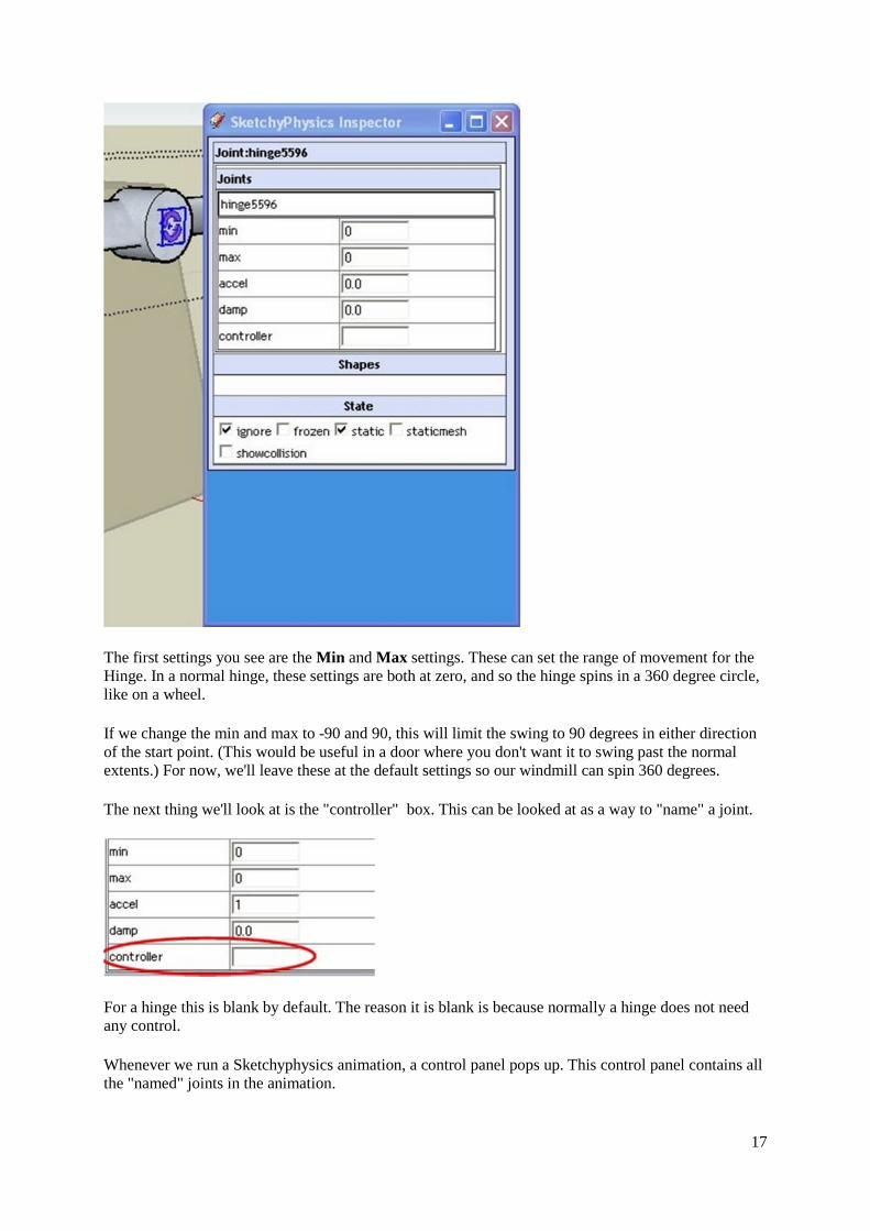
The first settings you see are the Min and Max settings. These can set the range of movement for theHinge. In a normal hinge, these settings are both at zero, and so the hinge spins in a 360 degree circle,like on a wheel.
If we change the min and max to -90 and 90, this will limit the swing to 90 degrees in either directionof the start point. (This would be useful in a door where you don't want it to swing past the normalextents.) For now, we'll leave these at the default settings so our windmill can spin 360 degrees.
The next thing we'll look at is the "controller" box. This can be looked at as a way to "name" a joint.
For a hinge this is blank by default. The reason it is blank is because normally a hinge does not needany control.
Whenever we run a Sketchyphysics animation, a control panel pops up. This control panel contains allthe "named" joints in the animation.
18
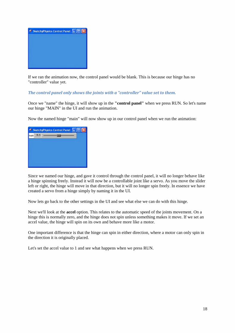
If we ran the animation now, the control panel would be blank. This is because our hinge has no"controller" value yet.
The control panel only shows the joints with a "controller" value set to them.
Once we "name" the hinge, it will show up in the "control panel" when we press RUN. So let's nameour hinge "MAIN" in the UI and run the animation.
Now the named hinge "main" will now show up in our control panel when we run the animation:
Since we named our hinge, and gave it control through the control panel, it will no longer behave likea hinge spinning freely. Instead it will now be a controllable joint like a servo. As you move the sliderleft or right, the hinge will move in that direction, but it will no longer spin freely. In essence we havecreated a servo from a hinge simply by naming it in the UI.
Now lets go back to the other settings in the UI and see what else we can do with this hinge.
Next we'll look at the accel option. This relates to the automatic speed of the joints movement. On ahinge this is normally zero, and the hinge does not spin unless something makes it move. If we set anaccel value, the hinge will spin on its own and behave more like a motor.
One important difference is that the hinge can spin in either direction, where a motor can only spin inthe direction it is originally placed.
Let's set the accel value to 1 and see what happens when we press RUN.

19
If you did not name the hinge by setting a value in the controller box, the hinge will spin in onedirection just like a motor.
If you did name the hinge in the "controller" box, you'll see the control panel pop up with the name ofthe hinge:
By default, the slider bar is at 0.5 (or at rest). By sliding it either left or right, we can make the hingespin in either direction. The further you slide it, the faster it will spin in that direction.
NOTE: This is just an example of using the UI, and the hinge is more of a hybrid than a truemotor. If you move the slider halfway in either direction, the hinge will try to act somewhatlike a servo and somewhat like a motor. When the slider is fully left or right, it will act like atrue motor. When precision is needed, use the appropriate joint for the job. (A motor or aservo.)
Another interesting thing we can do when setting the controller value is to set multiple joints to thesame controller name. By doing this, you can control many joints at once with one slider. We'll seean example of this on the next page when we add steering to our original car model.
But before we get to that, let’s look at the final option in our UI: the damp setting. You can use this tosmooth out "twitchy" joints and make them run more smoothly. Play around with different settings inthe above model and see how it affects the model.
Remember, each joint type has its own settings in the UI, and the only way to know how any settingwill affect that joint is to plug in some values and test it out.
Now that we have the basics of using the UI down, let's continue on with learning the UI and addsome steering and forward/ reverse control to our original car model.
Continue on te Advanced User Interface
20
Advanced SketchyPhysics...using the UI Part 2
Now we have some knowledge of the UI, let's use it to finish up our original car model andadd both steering and forward/ reverse capabilities.
Starting with our original model... if we wanted to make the car move, we could replace theoriginal rear hinges with motors. This would spin the wheels, but only in one direction. In ourcase we want both forward AND reverse, so we'll set up our two rear hinges as custom motorsusing the UI.
(You can download this model HERE to follow along with the tutorial.)
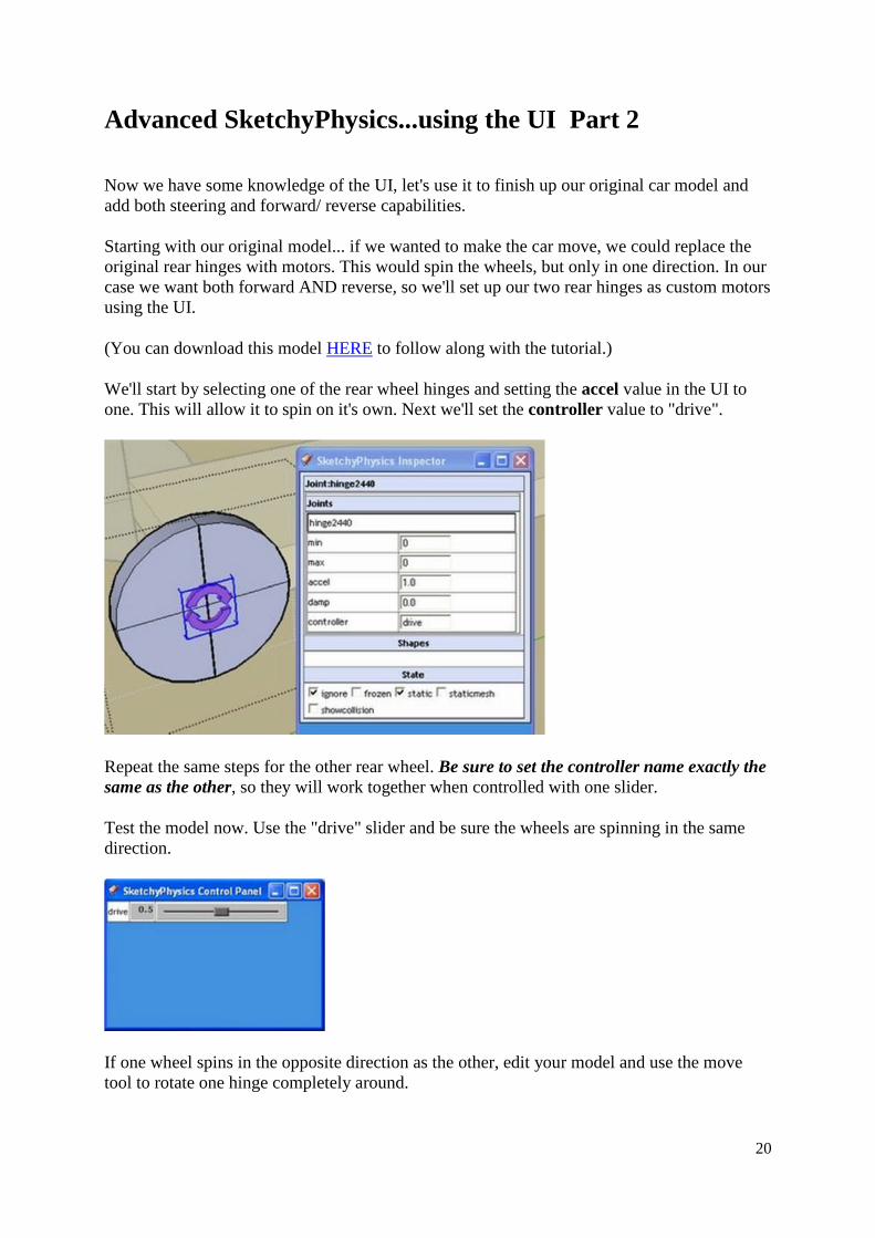
We'll start by selecting one of the rear wheel hinges and setting the accel value in the UI toone. This will allow it to spin on it's own. Next we'll set the controller value to "drive".
Repeat the same steps for the other rear wheel. Be sure to set the controller name exactly thesame as the other, so they will work together when controlled with one slider.
Test the model now. Use the "drive" slider and be sure the wheels are spinning in the samedirection.
If one wheel spins in the opposite direction as the other, edit your model and use the movetool to rotate one hinge completely around.
21
NOTE:
DO NOT use the "Flip" command shortcut! Using the flip command on parts of models to beused with SketchyPhysics usually will not work! Many models are completely messed upwhen you start "flipping" things. Always rotate a hinge using the move tool!
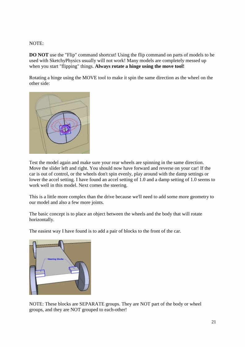
Rotating a hinge using the MOVE tool to make it spin the same direction as the wheel on theother side:
Test the model again and make sure your rear wheels are spinning in the same direction.Move the slider left and right. You should now have forward and reverse on your car! If thecar is out of control, or the wheels don't spin evenly, play around with the damp settings orlower the accel setting. I have found an accel setting of 1.0 and a damp setting of 1.0 seems towork well in this model. Next comes the steering.
This is a little more complex than the drive because we'll need to add some more geometry toour model and also a few more joints.
The basic concept is to place an object between the wheels and the body that will rotatehorizontally.
The easiest way I have found is to add a pair of blocks to the front of the car.
NOTE: These blocks are SEPARATE groups. They are NOT part of the body or wheelgroups, and they are NOT grouped to each-other!

Next we'll add a servo for each block. Group each servo and its block, then joint-connect eachservo to the body.
Now we'll need to use the UI to set the steering servos to behave as needed. Set each servo'smin and max to -45 and 45 to limit their swing. Also set their controller name the same (I'musing "steering") so they'll work together.
The next step is to make the wheels move with the steering blocks. So using the jointconnector tool, break the original connection of each wheels hinge to the body (using SHIFT)and make a new connection to their steering block. (Using CTRL.)
The final thing we need to do is to modify the body so the wheels have some room to turn.(Wheel-wells.) Here's one way of doing this:
Notice that the body is now made of two groand the nose of the body. If I simply push-pugeometry would still reflect a rectangle and tover, unable to turn.
Be sure to use the "show collision" option in
e
Sorry, no pictur22
uped objects grouped together. The main bodylled the original body and left it as one shape, thehe wheels would hit the "invisible" body left
the UI to shape your body until it works right.

23
One downside of changing the original body to two groups grouped together, is that by re-grouping the original group, it broke any joint-connections that were associated with itoriginally. We'll look at some troubleshooting below.
This is usually the point where people get frustrated with the model because things bind upand parts fall off. So let's look at some possible reasons for failure.
When things go wrong...
Stay calm, debug everything, and check your joint connections.
When I changed the body from one group to two (grouped) groups, it broke the original jointconnections. So I had to re-joint connect the rear hinges to the "new" body and also re-jointconnect the servos to the body as well. Follow these next few steps when troubleshooting astubborn model:
Anytime you explode a group, or group a group with another object (even a joint) theoriginal joints connected to it will be broken!!!
If things don't move like they should, or it looks like joints are "stretching", they're probablybinding against something. (Maybe something invisible...so DEBUG your geometry.)
If jointed parts fall off your model, remake the joint connections.
When all else fails, there is NO SHAME in deleting a joint completely and replacing it with anew one.
The above example was only one way to make the geometry work. I'm sure there are manymore ways to make it better. A steering arm comes to mind instead of my "magic" floatingsteering blocks! But either way, we now have a car that can roll forward and reverse, and alsosteer.
If you want to reference the finished model, it can be found HERE.
Here's a tip when testing your car:
After you press RUN, and before you start moving it around, Right-click the body and set thecamera to "FOLLOW". This will keep the car from running off your screen. So you candedicate more time to troubleshooting, and less time zooming and panning to follow the cararound.
Also note that this car is far from being complete, as all the joints need their accel and dampsettings tweaked. So there is still a lot of work to be done, but now you should have the toolsto make it through!


![UNOFFICIAL/UNAUTHENTICATED TRANSCRIPT observer... · 08/12/2017 · UNOFFICIAL/UNAUTHENTICATED TRANSCRIPT UNOFFICIAL/UNAUTHENTICATED TRANSCRIPT 18058 done. MTC [MR. TRIVETT]: Understood](https://img.pdfslide.us/doc/110x75/5ed2c475d9d6ff34b8636462/unofficialunauthenticated-transcript-observer-08122017-unofficialunauthenticated.jpg)
![UNOFFICIAL/UNAUTHENTICATED TRANSCRIPT 26 July 2019.]€¦ · UNOFFICIAL/UNAUTHENTICATED TRANSCRIPT UNOFFICIAL/UNAUTHENTICATED TRANSCRIPT 24485 [The R.M.C. 803 session was called to](https://img.pdfslide.us/doc/110x75/5f07260f7e708231d41b8c44/unofficialunauthenticated-transcript-26-july-2019-unofficialunauthenticated.jpg)