Embed Size (px)
Citation preview
“Intra-Network Routing Scheme using Mobile Agents”
byAjay L. Thakur
Outline
Objectives OSPF Overview Mobile Agents Related Works Proposed Best-Effort Routing Scheme Proposed QoS Routing Scheme Simulation Results Conclusion
Objectives
Develop a Routing Scheme using Mobile agents Given a source (s) and destination (d) find a
path Given a source (s) and destination (d) find a
path which satisfies QoS constraints like required Bandwidth ( Breq) and delay
Open Shortest Path First (OSPF)
Overview Uses link state routing algorithm To reduce the routing overhead it divides the full
Autonomous System (AS) into number of areas Each router maintains link state database for
routing domain Area Border Router (ABR) keeps separate database
for each area Routers periodically send Link State Advertisement
(LSA) into the network ABR routers send summary LSA to backbone area
and to the internal routers

OSPF Contd…
0
3
5
2
7
4
10
911
12
13
6
8
15
14
16
Area 1
Area 2
Area 3
Area 0
ABR router Internal Router
OSPF issues Memory Overhead
OSPF uses a link state database to keep track of all routers and networks within each attached area. With a complex topology, this database can be much larger and may limit the maximum size of an area.
Processor Overhead During steady state operation the OSPF CPU usage is
low, mainly due to the traffic between routers. However, when a topology change is detected, there is a large amount of processing required to support flooding of changes, and re-calculation of the routing table. In the existing implementations, the shortest path tree has to be computed from scratch after each link state change.
OSPF issues contd…
Synchronization of Database Database at all routers within area should be
synchronized. After changes in network it takes time to notify the change to all the routers within area. In between database is not synchronized and it may cause looping of packets.
Mobile Agents
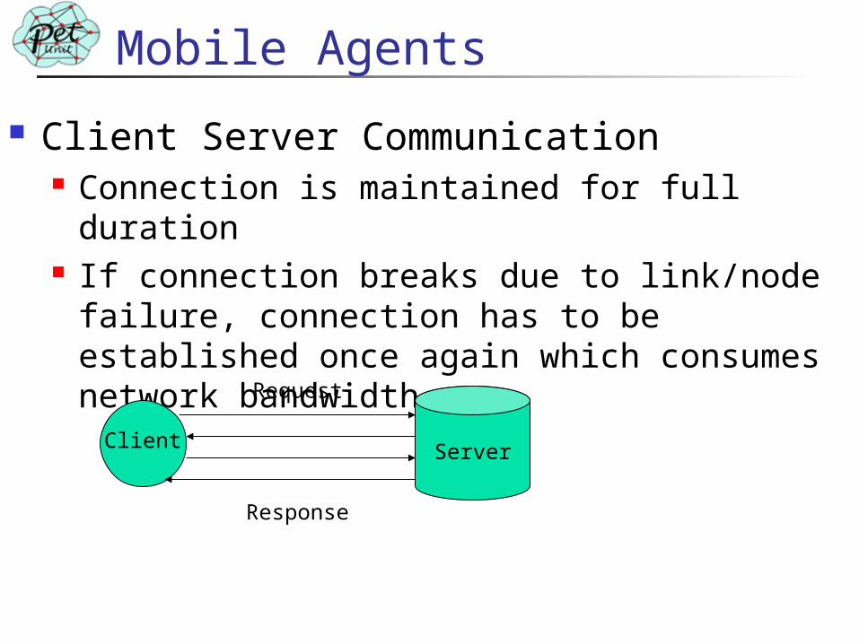
Client Server Communication Connection is maintained for full duration If connection breaks due to link/node failure,
connection has to be established once again which consumes network bandwidth
ServerClient
Request
Response

Mobile Agents
ClientServer
Mobile Agent Communication Mobile agent is a program that can be dispatched from one computer and delivered to a remote computer for execution. After execution mobile agent comes back with the result
MA
Result
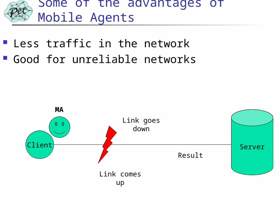
Some of the advantages of Mobile Agents
Less traffic in the network Good for unreliable networks
Client ServerResult
Link goes down
Link comes up
MA
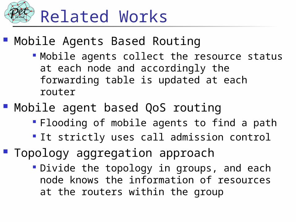
Related Works Mobile Agents Based Routing
Mobile agents collect the resource status at each node and accordingly the forwarding table is updated at each router
Mobile agent based QoS routing Flooding of mobile agents to find a path It strictly uses call admission control
Topology aggregation approach Divide the topology in groups, and each node
knows the information of resources at the routers within the group

Proposed Work
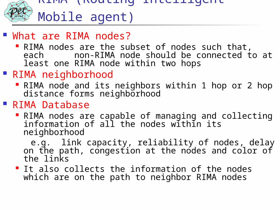
What are RIMA nodes? RIMA nodes are the subset of nodes such that, each
non-RIMA node should be connected to at least one RIMA node within two hops
RIMA neighborhood RIMA node and its neighbors within 1 hop or 2 hop
distance forms neighborhood RIMA Database
RIMA nodes are capable of managing and collecting information of all the nodes within its neighborhood
e.g. link capacity, reliability of nodes, delay on the path, congestion at the nodes and color of the links
It also collects the information of the nodes which are on the path to neighbor RIMA nodes
RIMA (Routing Intelligent Mobile agent)
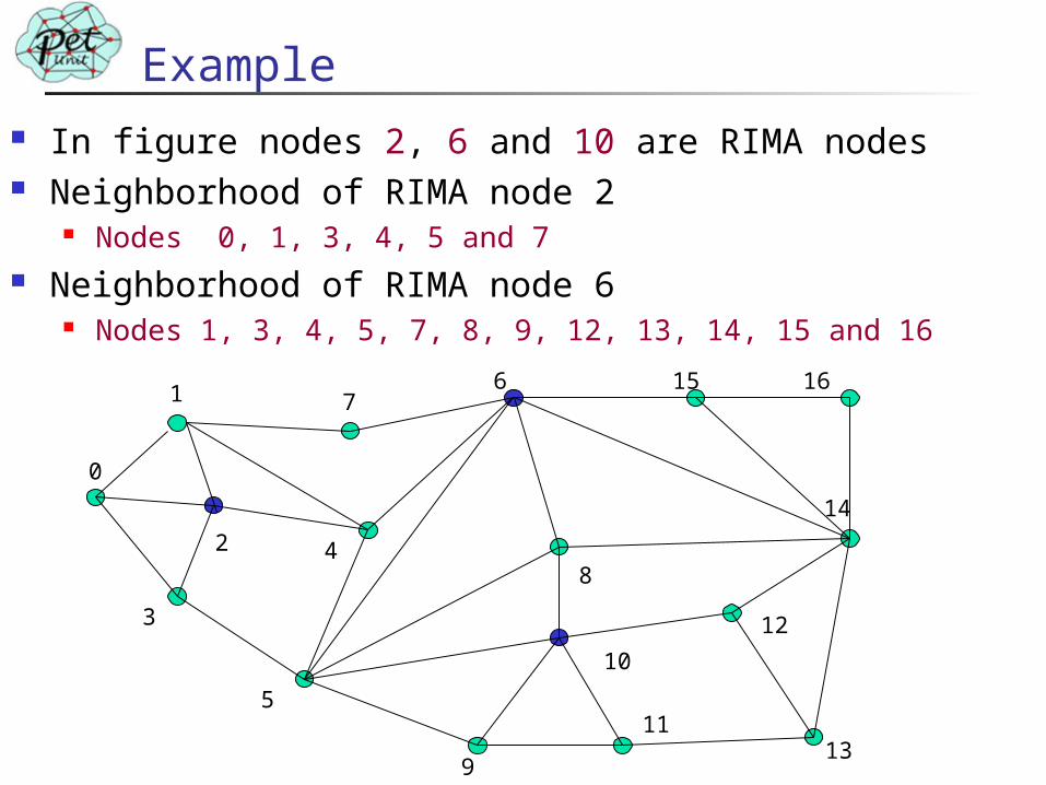
In figure nodes 2, 6 and 10 are RIMA nodes Neighborhood of RIMA node 2
Nodes 0, 1, 3, 4, 5 and 7 Neighborhood of RIMA node 6
Nodes 1, 3, 4, 5, 7, 8, 9, 12, 13, 14, 15 and 16
Example
15 166
3
2
7
12
8
10
11
1
5
4
14
0
913
RIMA Placement Algorithm
RIMA nodes are more responsible for routing of packets and it collects the database which is used for routing
RIMA placement algorithm takes into consideration some of the desirable properties Processing power Average normalized link capacity Reliability Connectivity

RIMA Placement Algorithm contd…
• Send node information packet to neighbors• Receive information packet from neighbors
• Calculate weight factor• Send weight factor to neighbors
Weight of node > Weight of all neighbors
Announce itself as RIMA node
Yes
Start timer and wait for RIMA announcement message
RIMA announcement Message received ?
Yes
No
Announce itself as RIMA node
No
Finding path between RIMAs RIMA node sends mobile agents to find
path(s) to neighbor RIMA nodes While traveling mobile agent also collect the
path information like BW available on links When mobile agent reaches at RIMA node it
gives all the information to the RIMA node Mobile agent comes back to source RIMA
node and gives information to source RIMA node
RIMA nodes estimate the path delay by using time stamp in mobile agent
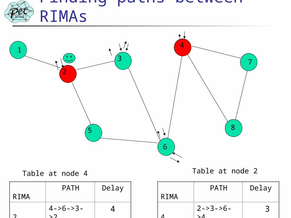
Finding paths between RIMAs
1
2
3
4
5
6
7
8
RIMA PATH Delay
2 4->6->3->2
4
Table at node 4
RIMA PATH Delay
4 2->3->6->4
3
Table at node 2
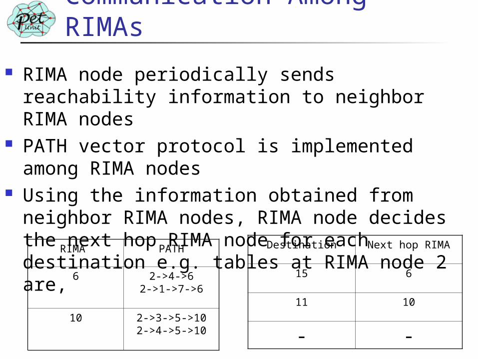
Communication Among RIMAs
RIMA node periodically sends reachability information to neighbor RIMA nodes
PATH vector protocol is implemented among RIMA nodes
Using the information obtained from neighbor RIMA nodes, RIMA node decides the next hop RIMA node for each destination e.g. tables at RIMA node 2 are, Destination Next hop RIMA
15 6
11 10
- -
RIMA PATH
6 2->4->62->1->7->6
10 2->3->5->102->4->5->10
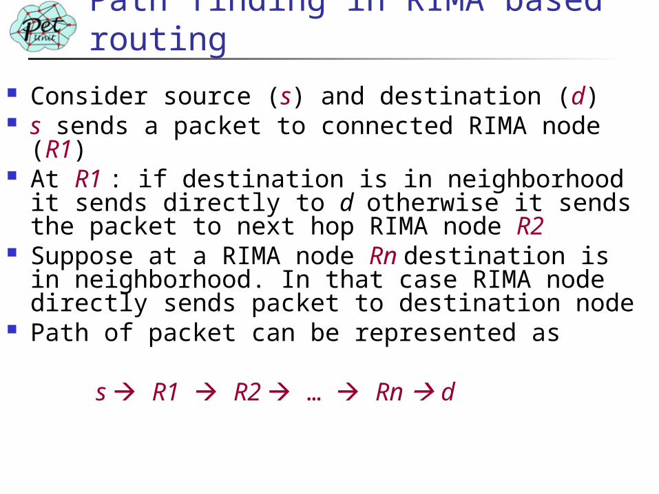
Path finding in RIMA based routing
Consider source (s) and destination (d) s sends a packet to connected RIMA node (R1) At R1 : if destination is in neighborhood it
sends directly to d otherwise it sends the packet to next hop RIMA node R2
Suppose at a RIMA node Rn destination is in neighborhood. In that case RIMA node directly sends packet to destination node
Path of packet can be represented as s R1 R2 … Rn d
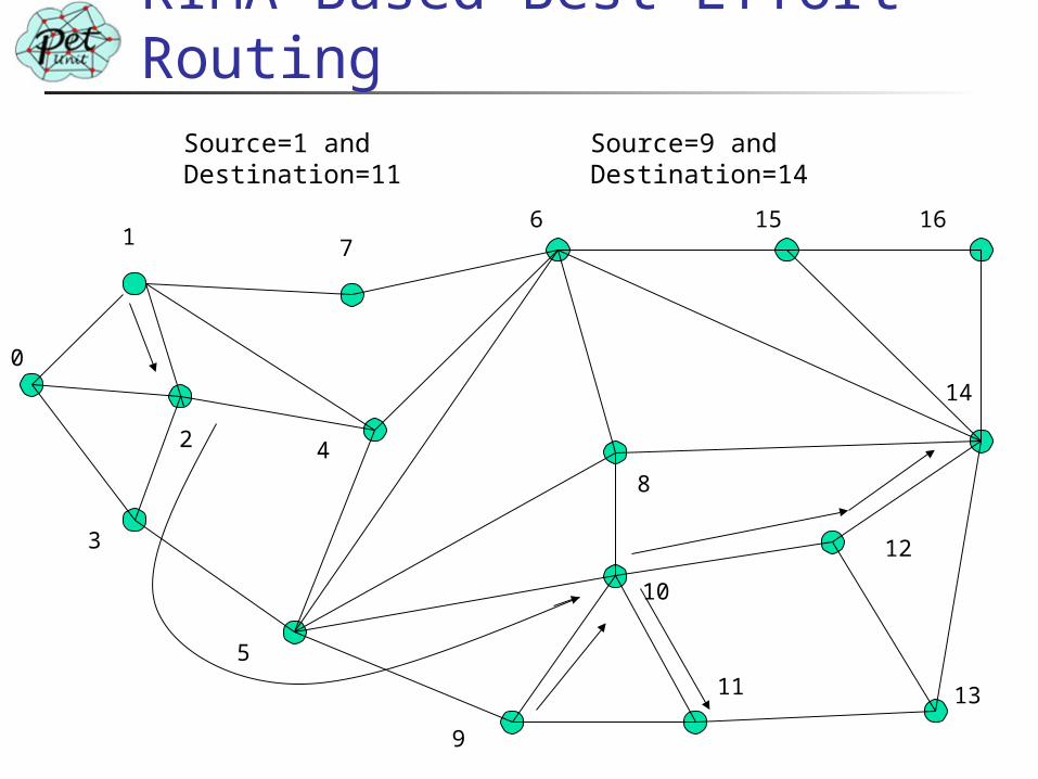
RIMA Based Best-Effort Routing
15 166
9
3
2
7
12
8
10
11
1
5
4
14
0
13
Source=1 and Destination=11
Source=9 and Destination=14
Dynamic Network Behavior After link/node failure corresponding
node sends update message to only connected RIMA nodes and one hop neighbor nodes
RIMA node updates its neighborhood If there is change in cost to reach some
node in neighborhood Send reachability information to neighbor
RIMA nodes If neighborhood is unchanged
No need to send messages
Quality of Service (QoS) Need of QoS
Internet provides Best-Effort service New Emerging real time applications need
Guaranteed QoS; specially in case of interactive application like IP telephony, video conferencing
Metrics used in QoS routing Bandwidth, Delay, Delay jitter, packet loss
Issues in QoS Knowledge propagation and maintenance: When to
send the link state information to other network Periodic: Router periodically send Threshold based: When significant change in resources
Metric and path computation How to measure and collect network state information How to compute routes based on the information collected
RIMA based QoS Routing Scheme
On-Demand Routing algorithm QoS metrics used are bandwidth and
delay RIMA based QoS routing is same as RIMA
based Best-effort routing but only difference is that each RIMA node strictly selects a path according to QoS constraints
Consider source s , destination d , requested bandwidth Breq and delay Δmax
RIMA based QoS Routing Scheme
Source node sends mobile agent to a connected RIMA node on the path with sufficient bandwidth and minimum delay
At RIMA node: If destination is within a neighborhood or it is on the path to other RIMA node and feasible path exist, then RIMA node directly sends the mobile agent to
destination node otherwise RIMA node sends the mobile agent to next
hop RIMA node on the path which satisfies QoS constraints
When mobile agent reaches to destination, destination node sends reservation request on the same path
When source node gets mobile agent it finds the time taken by mobile agent to setup the connection and it estimates delay to destination. If application can sustain that much delay then it sends the packet. Otherwise it releases the resources
QoS Routing
15 166
9
3
2
7
12
8
10
11
1
5
4
14
0
13
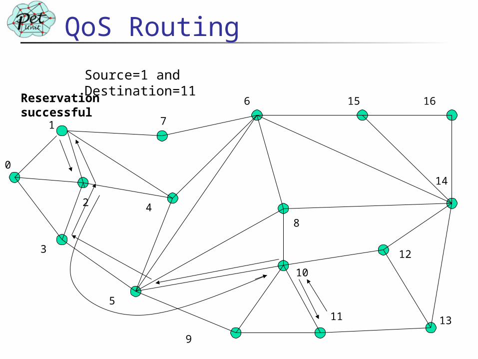
Source=1 and Destination=11
Reservation successful
Modified RIMA based QoS Routing
In previous algorithm Source sends request to only one RIMA node
In modified RIMA based QoS routing Source sends the path request to all the connected
RIMA nodes Advantage
More than one mobile agent reaches at destination hence possibility of finding path increases i.e. increase in success ratio
Disadvantage Cost per connection increases as more requests are
send in the network Destination will choose one path and sends
the reservation request on that path
Modified QoS Routing
15 166
9
3
2
7
12
8
10
11
1
5
4
14
0
13
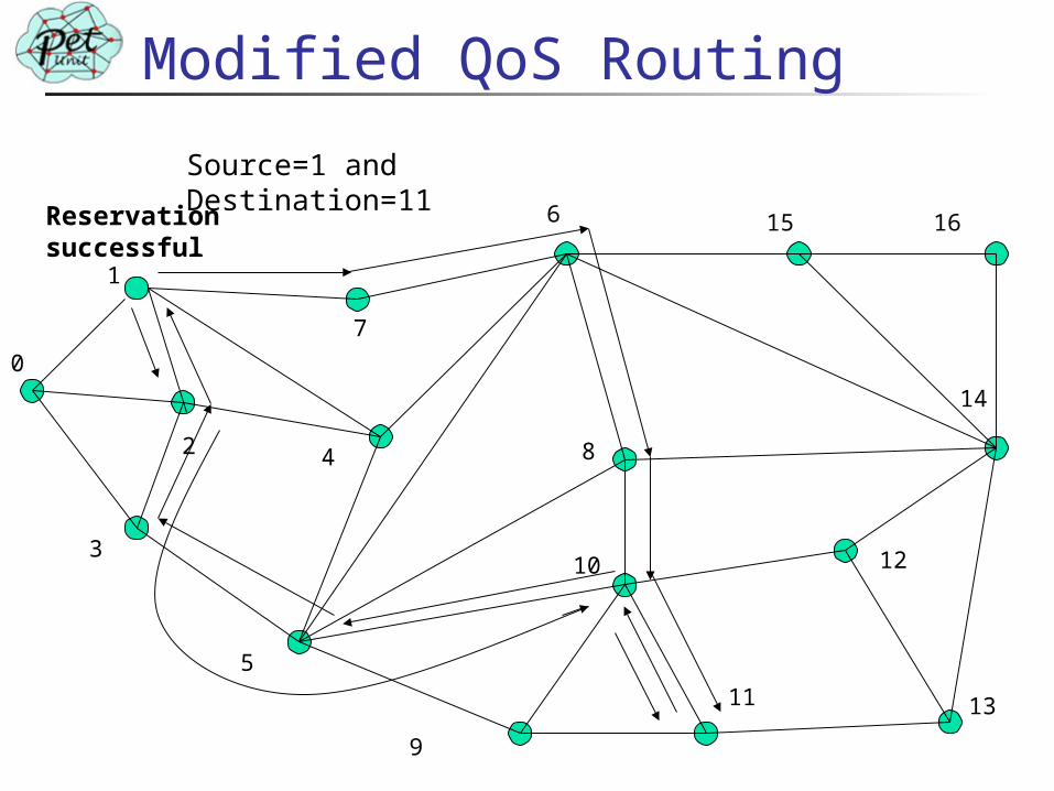
Source=1 and Destination=11
Reservation successful
Simulation of Intranet
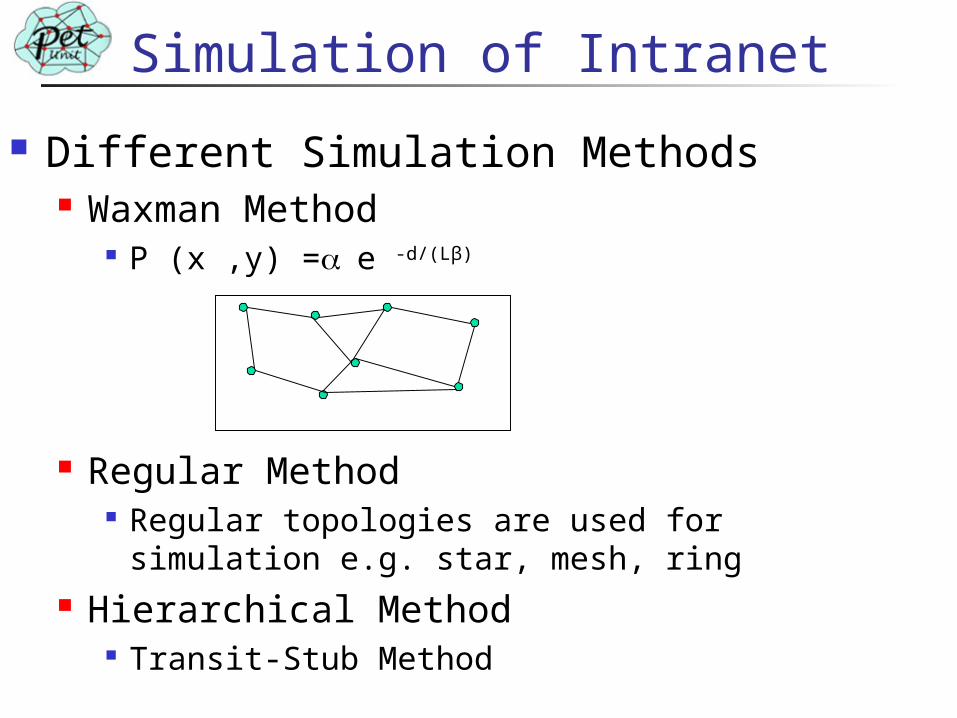
Different Simulation Methods Waxman Method
P (x ,y) =e -d/(Lβ)
Regular Method Regular topologies are used for simulation e.g.
star, mesh, ring Hierarchical Method
Transit-Stub Method
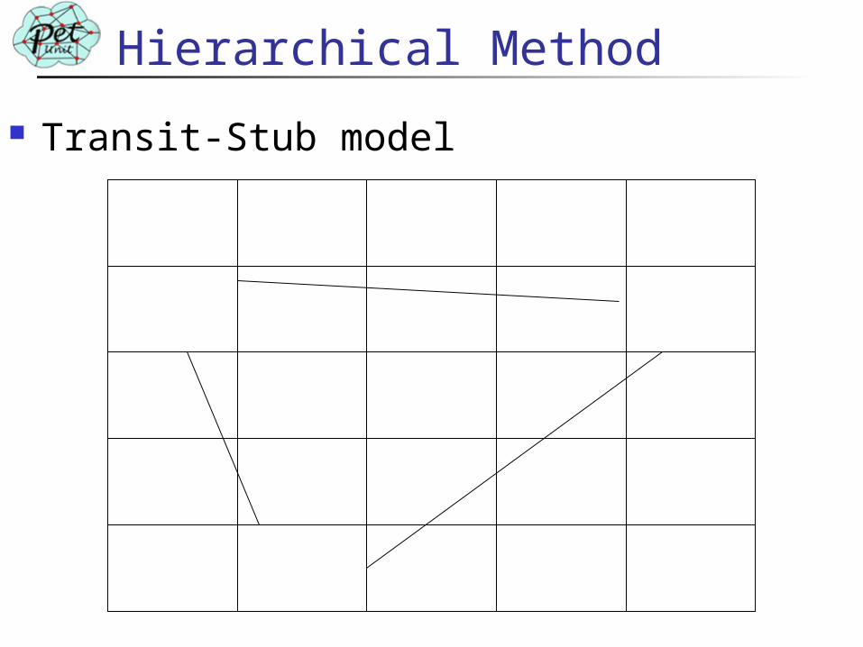
Hierarchical Method
Transit-Stub model
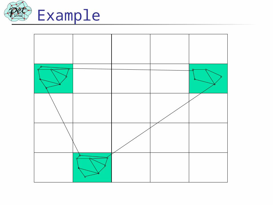
Example
OSPF Simulation
Topology is generated using Transit-Stub model and edges are added using Waxman’s method
Total domain is divided into NA areas + backbone area.
Each area has more than one ABR ( Area Border Router)
Topology size is changed by changing Number of areas and Number of routers per area
Simulation
RIMA topology simulation We consider topology as Flat topology Generate the topology using Transit-Stub
model and added edges using Waxman’s method
RIMA placement algorithm decides RIMA nodes
Assumption and Features of Intranet Simulation
Assumptions Propagation delay considered to be 1 unit time Error free transmission Links are symmetric No packet loss at the router due to insufficient buffer
Features Simulated up to 800 nodes At each router two queues one for best effort service
and other for guaranteed service Best effort traffic is background traffic Weighted fair queue is used at each router Processing delay, transmission delay and queuing
delays are considered
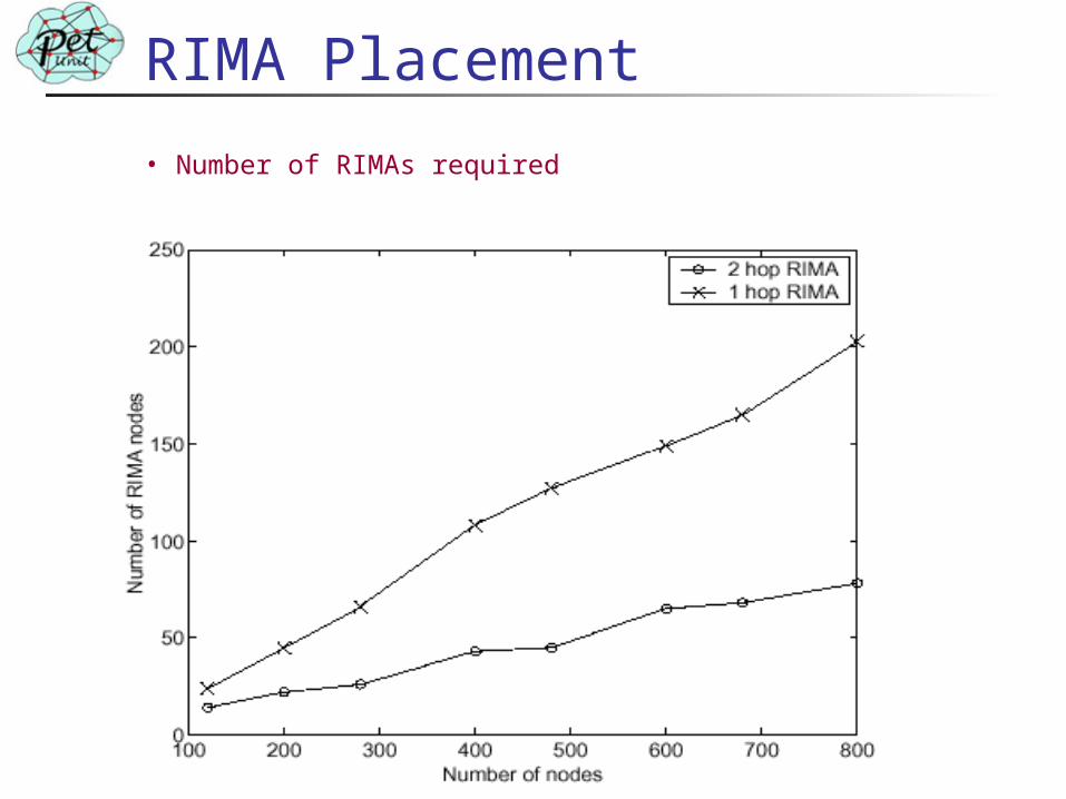
RIMA Placement
• Number of RIMAs required
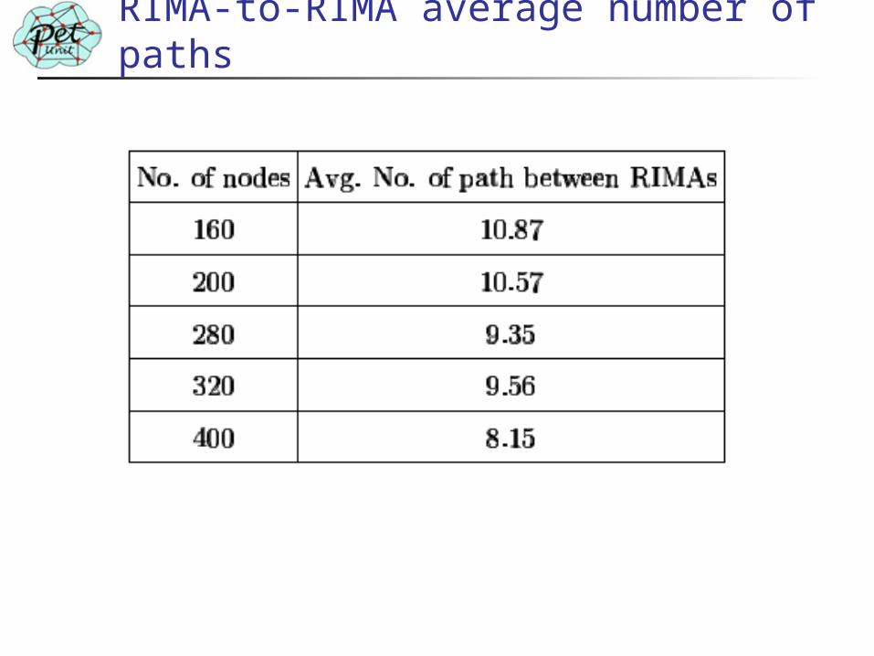
RIMA-to-RIMA average number of paths
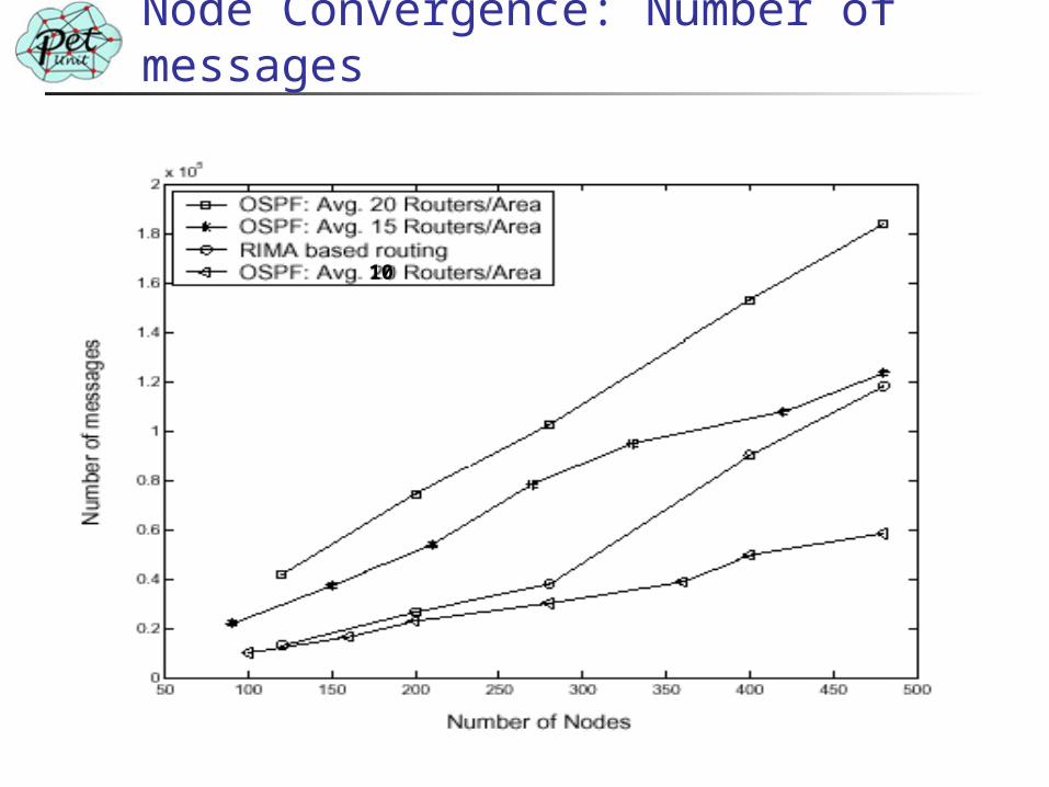
Node Convergence: Number of messages
10
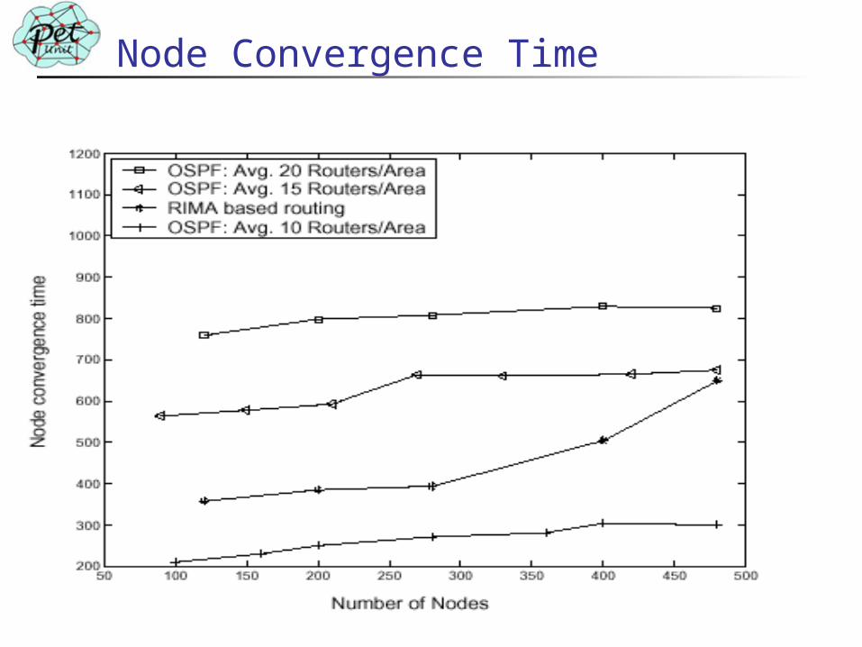
Node Convergence Time
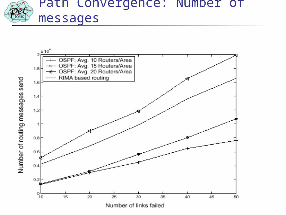
Path Convergence: Number of messages
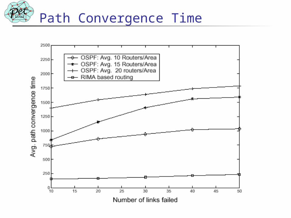
Path Convergence Time
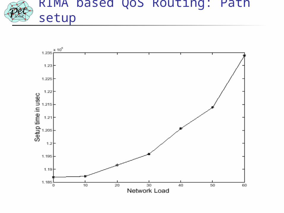
RIMA based QoS Routing: Path setup
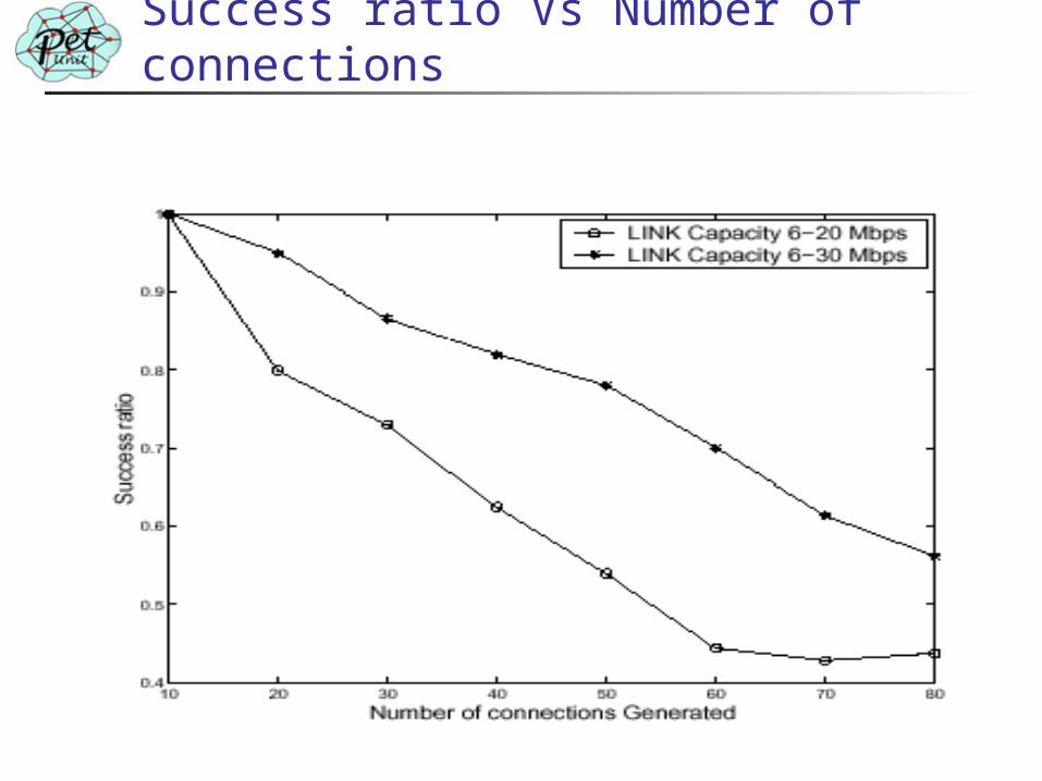
Success ratio Vs Number of connections
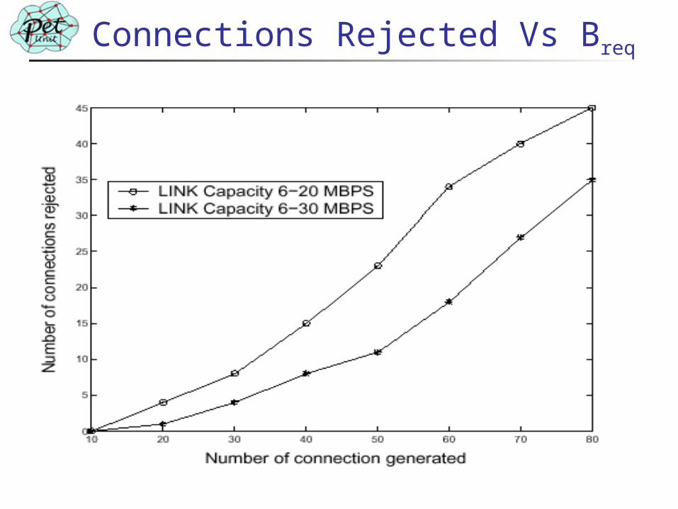
Connections Rejected Vs Breq
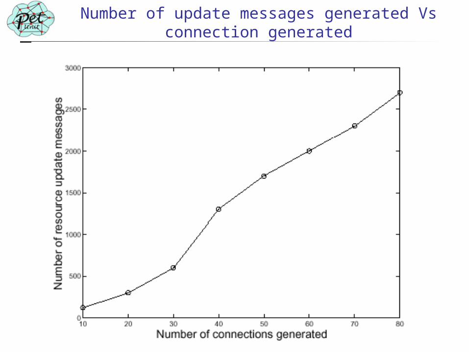
Number of update messages generated Vs connection generated
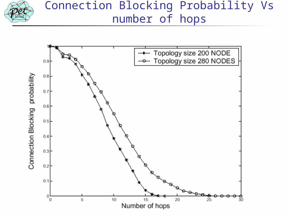
Connection Blocking Probability Vs number of hops
Conclusion
Developed RIMA based Best-effort routing scheme
Developed RIMA based QoS routing scheme
Comparisons of the performance of proposed routing scheme and OSPF routing
Publications (submitted) Ajay L. Thakur and P. Venkataram , "RIMA Based
Intra-Network QoS Routing Scheme", Computer Communications Journal (Elsevier)
Ajay L. Thakur and P. Venkataram , "Intra-Network
Routing Scheme using Mobile Agents”, SPCOM 2004

Thank You!


![Thakur Educational Trust’s (Regd.) THAKUR VIDYA … IV.pdf · Thakur Educational Trust’s (Regd.) THAKUR VIDYA MANDIR HIGH SCHOOL & JUNIOR COLLEGE ... Q1 A] Fill in the blanks](https://img.pdfslide.us/doc/110x75/5af067447f8b9abc788d1c95/thakur-educational-trusts-regd-thakur-vidya-ivpdfthakur-educational-trusts.jpg)