Embed Size (px)
Citation preview

Interrupts Useful in dealing with:
Random processes; I/O devices with low data transfer rates.
The interface: INTR (interrupt request) and NMI (Non
maskable interrupt) - inputs for external devices to request interrupt servicing.
INTA’ (interrupt acknowledge) – output used by CPU to acknowledge interrups.

Interrupt Vector Table Table located at
addresses 000000H – 0003FFH, the first 1024 bytes of memory.
Type 32 - 255User interrupt vectors
.
.Type 17 - 31
ReservedType 16
Coprocessor errorType 15
Not assignedType 14
Page faultType 13
General protectionType 12
Stack segment overrunType 11
Segment not presentType 10
Invalid task sate segmentType 9
Coprocessor segment overrunType 8
Double faultType 7
Coprocessor not availableType 6
Undefined opcodeType 5
BOUNDType 4
Overflow (INTO)Type 3
1 byte breakpointType 2NMI pinType 1
Single-stepType 0
Divide error000H
044H
080H
010H
00CH
008H
004H
020H
01CH
018H
014H
030H
02CH
028H
024H
040H
03CH
038H
034H

BOUND, INTO, INT, INT3 and IRET BOUND and INTO are conditional interrupts.
BOUND AX,DATA IF AX is less than DATA+1:DATA then an INT 5 occurs. IF AX is greater than DATA+3:DATA+2 then an INT 5
occurs. IF AX is within bounds of the two words in memory
(DATA+1:DATA ≤ AX ≤ DATA+3:DATA+2) then an INT 5 does not occur.
INTO If OF=1 then INT 4 occurs. If OF=0 then INTO performs a NOP operation and the
next instruction in the program is executed.

BOUND, INTO, INT, INT3 and IRET INT type INT 3 – Breakpoint interrupt IRET These instructions modify the EIP register to be
the address stored at: The IDT. The interrupt type or number is used to
identify which element of the IDT holds the addresses of the desired interrupt service subroutines;
The stack. The address stored in the stack by the INT or INTO instruction. This address identifies the return point after the interrupts execution.

Sequence of Events When the microprocessor finishes
executing an instruction it determines if an interrupt is active by checking: Instruction execution; Single-step; NMI; Coprocessor segment overrun; INTR; INT.
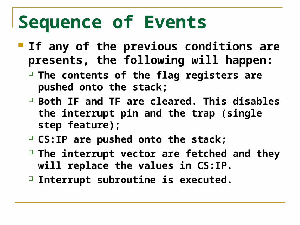
Sequence of Events If any of the previous conditions are
presents, the following will happen: The contents of the flag registers are pushed
onto the stack; Both IF and TF are cleared. This disables the
interrupt pin and the trap (single step feature); CS:IP are pushed onto the stack; The interrupt vector are fetched and they will
replace the values in CS:IP. Interrupt subroutine is executed.
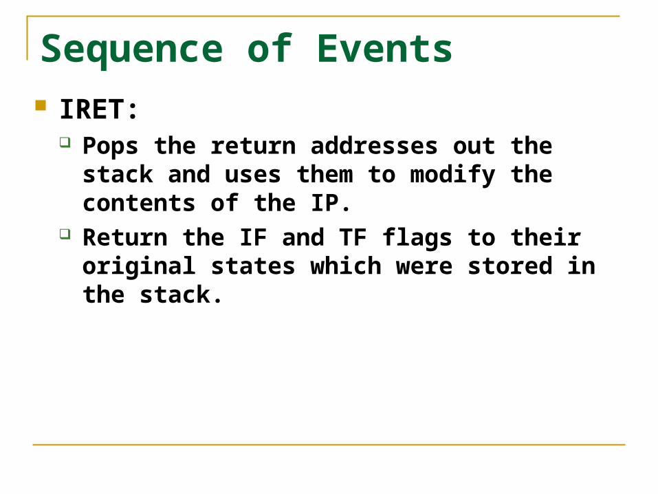
Sequence of Events IRET:
Pops the return addresses out the stack and uses them to modify the contents of the IP.
Return the IF and TF flags to their original states which were stored in the stack.

Hardware Interrupt Notice the sequence
of events described in the timing diagram: Interrupt request is
asserted; Interrupt acknowledge
is asserted twice; Vector is placed on the
data bus on the second pulse of the interrupt acknowledge signal.

Simple Hardware Interrupt Circuit This circuit places
vector number 80H on the data bus when the interrupt acknowledge signal is asserted.

8255 Circuit With Interrupt The 8255 generates
the interrupt through port C after it receives the request from the keyboard.
The 74LS244 places the interrupt vector on the data bus when the interrupt acknowledge is received.

8259A PIC The 8259A programmable interrupt
controller: Adds vectored priority encoded interrupts to
the microcontroller; Can handle up to 64 interrupt requests. This
requires the use of a master and eight slaves; Built by Intel and other manufacturers.
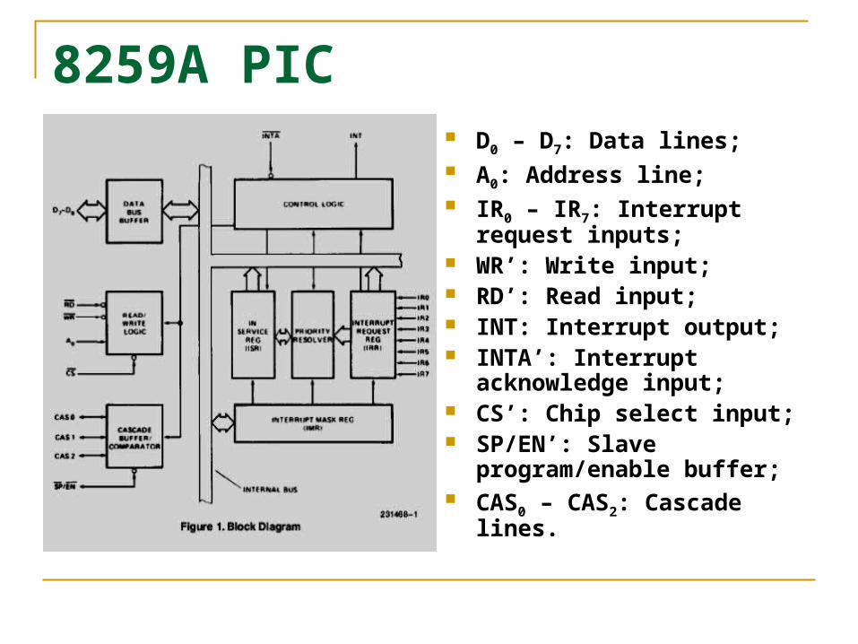
8259A PIC D0 – D7: Data lines; A0: Address line; IR0 – IR7: Interrupt request
inputs; WR’: Write input; RD’: Read input; INT: Interrupt output; INTA’: Interrupt
acknowledge input; CS’: Chip select input; SP/EN’: Slave
program/enable buffer; CAS0 – CAS2: Cascade lines.

8259A PIC

Cascading the 8259A PIC

Programming the 8259A The 8259A is programmed by properly
initializing: 4 ICWs - Initialization command words; 3 OCWs – Operation command words;
The initialization procedure may not need to initialize all of them.

Programming the 8259A
Use the flow chart shown to the left to guide you in which order and how many ICWs you may need to initialize.
ICWs must be initialized before the OCWs.

ICW1 and ICW2

ICW3 and ICW4

OCW1 and OCW2

OCW3