Embed Size (px)
Citation preview
1
Interrupts (II)
Lecturer: Sri Parameswaran
Notes by: Annie Guo
2
External Interrupts
The external interrupts are triggered by the
INT7:0 pins.
If enabled, the interrupts will trigger even if the
INT7:0 are configured as outputs
This feature provides a way of generating a software
interrupt.
Can be triggered by a falling or rising edge or a
logic level
Specified in External Interrupt Control Register
▪ EICRA (for INT3:0)
▪ EICRB (for INT7:4)
3
External Interrupts (cont.)
To enable an interrupt, two bits must be set
I bit in SREG
INTx bit in EIMSK
To activate an interrupt, the following must be
met:
The interrupt must be enabled
The associated external pin must have a
designed signal asserted.
4
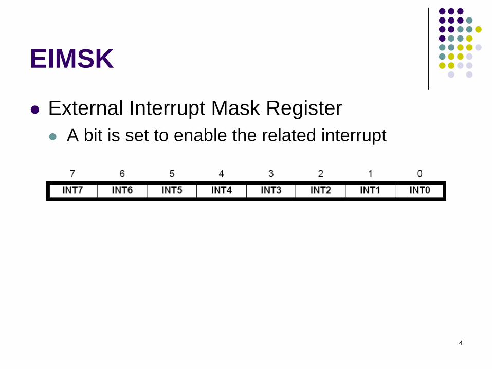
EIMSK
External Interrupt Mask Register
A bit is set to enable the related interrupt
5
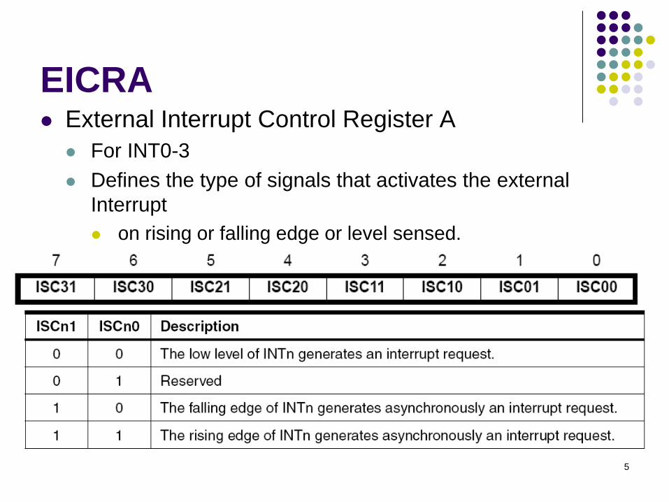
EICRA External Interrupt Control Register A
For INT0-3
Defines the type of signals that activates the external
Interrupt
on rising or falling edge or level sensed.
6
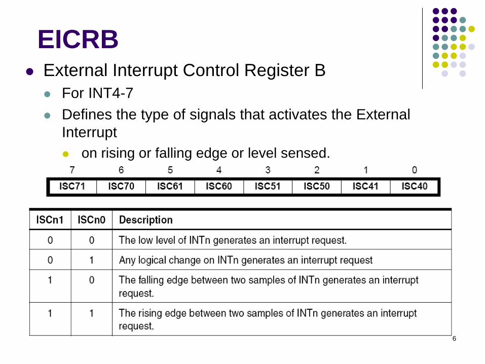
EICRB External Interrupt Control Register B
For INT4-7
Defines the type of signals that activates the External
Interrupt
on rising or falling edge or level sensed.
7
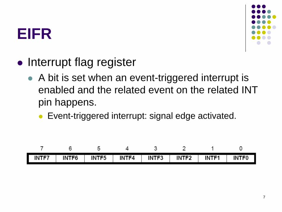
EIFR
Interrupt flag register
A bit is set when an event-triggered interrupt is
enabled and the related event on the related INT
pin happens.
Event-triggered interrupt: signal edge activated.
8
Example 1
Design a system, where the state of LEDs
toggles under the control of the user.
9
Example 1 (solution)
Use an external interrupt
Connect the external interrupt pin to a push button
When the button pressed, the interrupt is generated
In the assembly code
Set up the interrupt
Set up the interrupt vector
Enable the interrupt
Write a service routine for this interrupt
Change the display pattern
Write the pattern to the port connected to the LEDs

10
Code for Example 1.include "m2560def.inc“
.def temp =r16
.def output = r17
.def count = r18
.equ PATTERN = 0b01010101
; set up interrupt vectorsjmp RESET
.org INT0addrjmp EXT_INT0
RESET:ldi temp, low(RAMEND) ; initialize stackout SPL, templdi temp, high(RAMEND)out SPH, temp
ser temp ; set Port C as outputout DDRC, tempout PORTC, templdi output, PATTERN
; continued
11
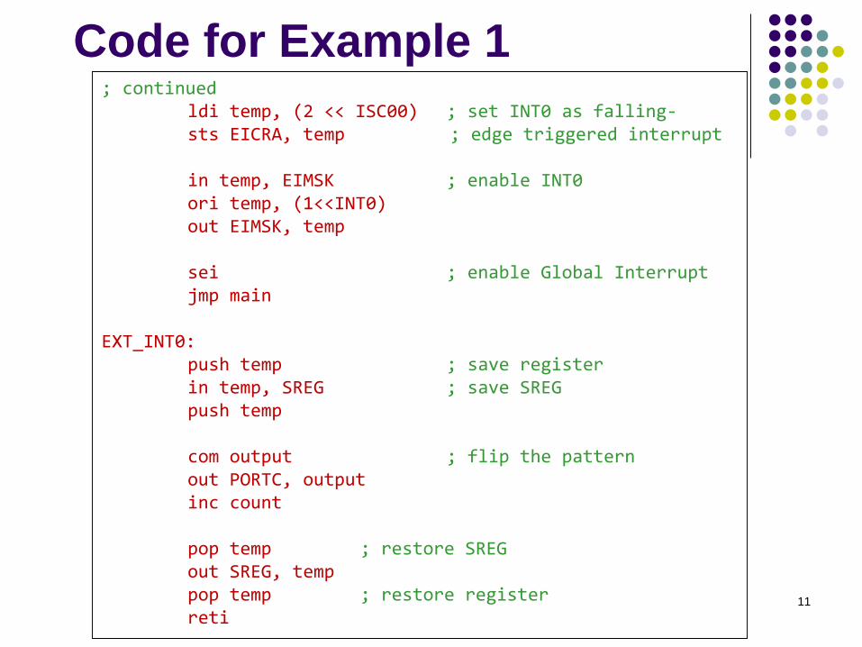
Code for Example 1; continued
ldi temp, (2 << ISC00) ; set INT0 as falling-sts EICRA, temp ; edge triggered interrupt
in temp, EIMSK ; enable INT0ori temp, (1<<INT0)out EIMSK, temp
sei ; enable Global Interruptjmp main
EXT_INT0:push temp ; save registerin temp, SREG ; save SREGpush temp
com output ; flip the patternout PORTC, outputinc count
pop temp ; restore SREGout SREG, temppop temp ; restore registerreti
12
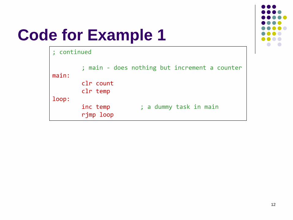
Code for Example 1; continued
; main - does nothing but increment a countermain:
clr countclr temp
loop:inc temp ; a dummy task in mainrjmp loop
13
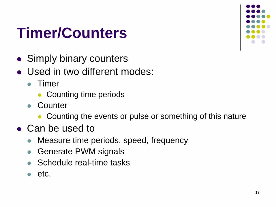
Timer/Counters
Simply binary counters
Used in two different modes: Timer
Counting time periods
Counter
Counting the events or pulse or something of this nature
Can be used to Measure time periods, speed, frequency
Generate PWM signals
Schedule real-time tasks
etc.
14
Timer/Counters in AVR
In AVR, there are 8-bit and 16-bit
timer/counters.
Timer 0 and Timer 2: 8-bit
Timer 1,3-5 16-bit
15
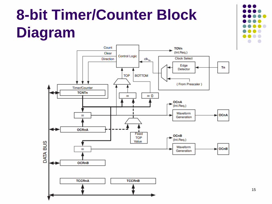
8-bit Timer/Counter Block
Diagram
16
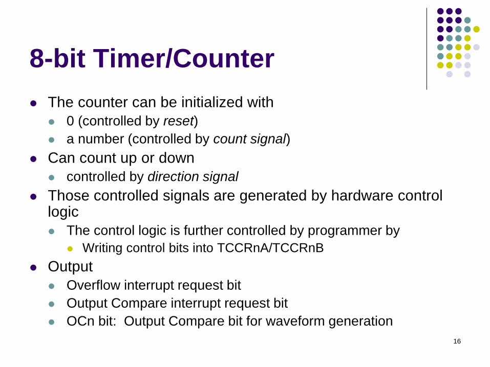
8-bit Timer/Counter
The counter can be initialized with
0 (controlled by reset)
a number (controlled by count signal)
Can count up or down
controlled by direction signal
Those controlled signals are generated by hardware control logic
The control logic is further controlled by programmer by
Writing control bits into TCCRnA/TCCRnB
Output
Overflow interrupt request bit
Output Compare interrupt request bit
OCn bit: Output Compare bit for waveform generation
17
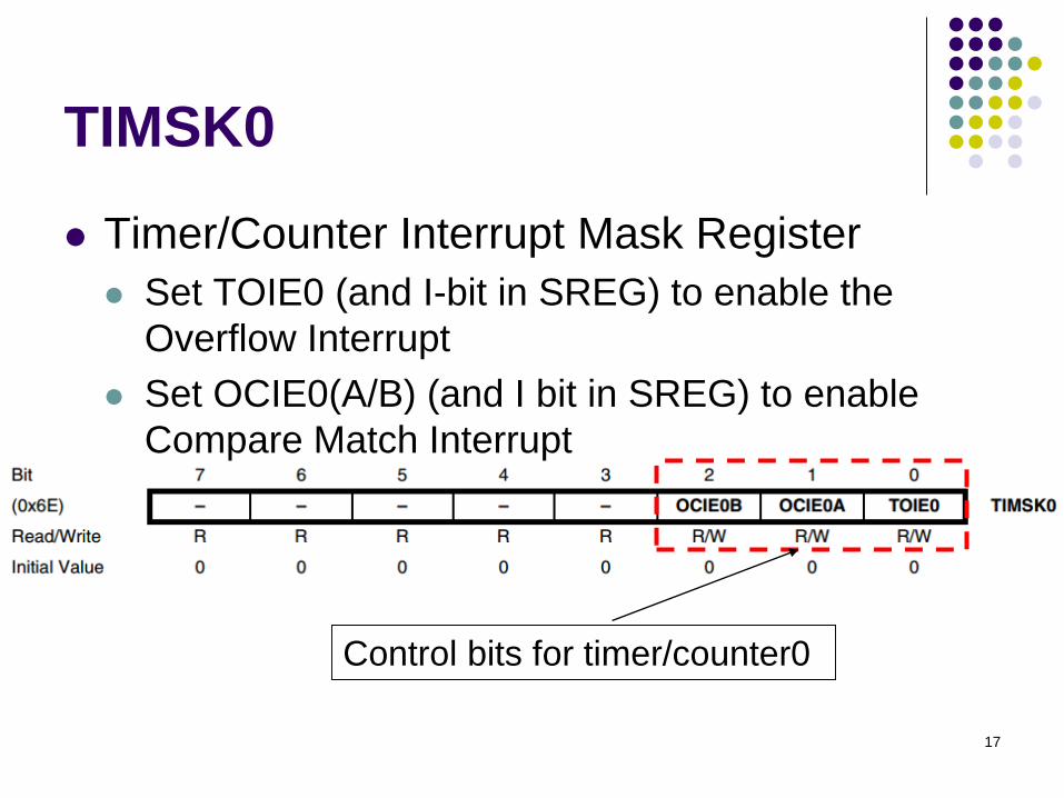
TIMSK0
Timer/Counter Interrupt Mask Register
Set TOIE0 (and I-bit in SREG) to enable the
Overflow Interrupt
Set OCIE0(A/B) (and I bit in SREG) to enable
Compare Match Interrupt
Control bits for timer/counter0
18
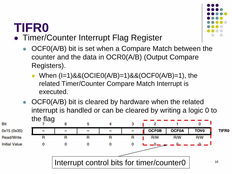
TIFR0 Timer/Counter Interrupt Flag Register
OCF0(A/B) bit is set when a Compare Match between the
counter and the data in OCR0(A/B) (Output Compare
Registers).
When (I=1)&&(OCIE0(A/B)=1)&&(OCF0(A/B)=1), the
related Timer/Counter Compare Match Interrupt is
executed.
OCF0(A/B) bit is cleared by hardware when the related
interrupt is handled or can be cleared by writing a logic 0 to
the flag
Interrupt control bits for timer/counter0
19
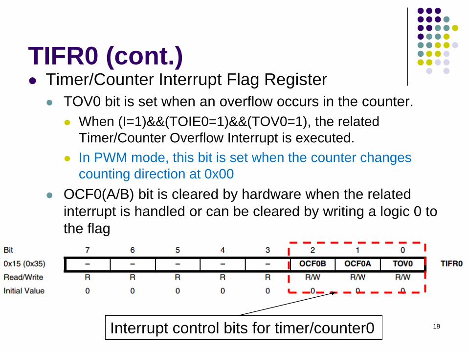
TIFR0 (cont.) Timer/Counter Interrupt Flag Register
TOV0 bit is set when an overflow occurs in the counter.
When (I=1)&&(TOIE0=1)&&(TOV0=1), the related
Timer/Counter Overflow Interrupt is executed.
In PWM mode, this bit is set when the counter changes
counting direction at 0x00
OCF0(A/B) bit is cleared by hardware when the related
interrupt is handled or can be cleared by writing a logic 0 to
the flag
Interrupt control bits for timer/counter0
20
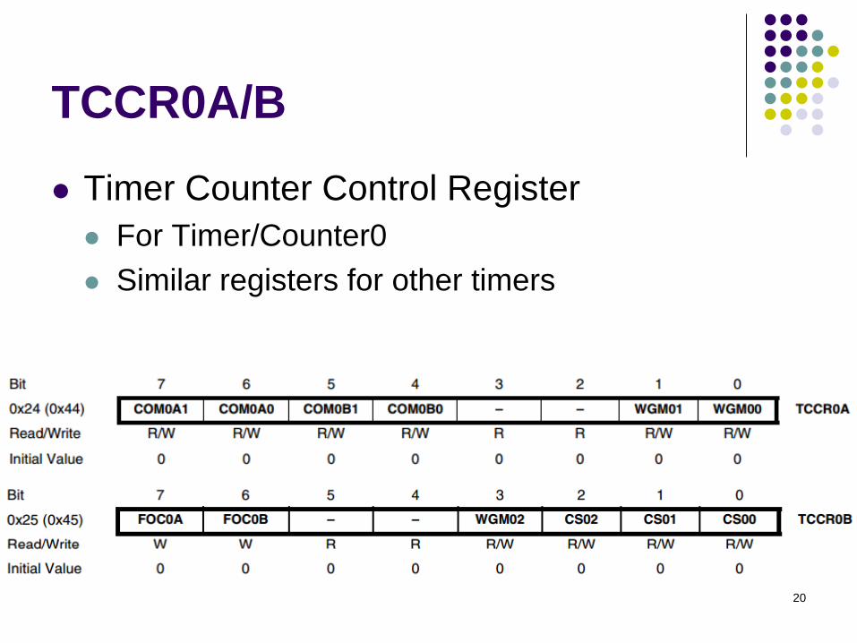
TCCR0A/B
Timer Counter Control Register
For Timer/Counter0
Similar registers for other timers
21
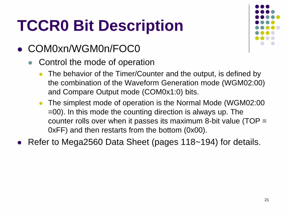
TCCR0 Bit Description
COM0xn/WGM0n/FOC0
Control the mode of operation
The behavior of the Timer/Counter and the output, is defined by
the combination of the Waveform Generation mode (WGM02:00)
and Compare Output mode (COM0x1:0) bits.
The simplest mode of operation is the Normal Mode (WGM02:00
=00). In this mode the counting direction is always up. The
counter rolls over when it passes its maximum 8-bit value (TOP =
0xFF) and then restarts from the bottom (0x00).
Refer to Mega2560 Data Sheet (pages 118~194) for details.
22
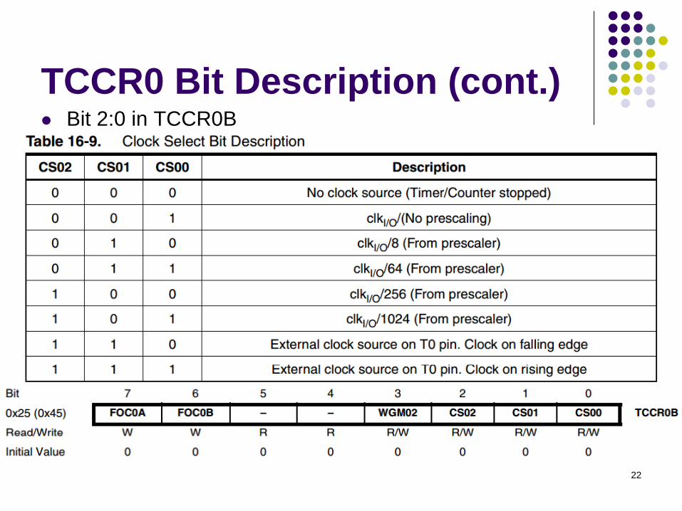
TCCR0 Bit Description (cont.) Bit 2:0 in TCCR0B
Control the clock selection
23
Example 2
Implement a scheduler that can execute a
task every one second.
24
Example 2 (solution)
Use Timer0 to count the time
Let’s set Timer0 prescaler to 8
The time-out for the setting should be▪ 256*(clock period) = 256*8/(16 MHz)
= 128 us
▪ Namely, we can set the Timer0 overflow interrupt that is to occur every 128 us.
▪ Note, Clktos = 1/16 MHz (obtained from the data sheet)
For one second, there are ▪ 1000000/128 = ~7812 interrupts
In code,
Set Timer0 interrupt to occur every 128 microseconds
Use a counter to count to 7812 interrupts for counting 1 second
To observe the 1 second time period, toggle an LED every second.
25
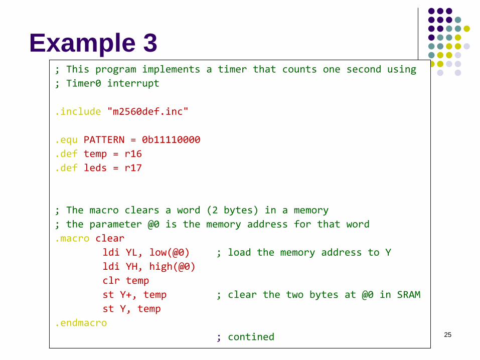
Example 3; This program implements a timer that counts one second using
; Timer0 interrupt
.include "m2560def.inc"
.equ PATTERN = 0b11110000
.def temp = r16
.def leds = r17
; The macro clears a word (2 bytes) in a memory
; the parameter @0 is the memory address for that word
.macro clear
ldi YL, low(@0) ; load the memory address to Y
ldi YH, high(@0)
clr temp
st Y+, temp ; clear the two bytes at @0 in SRAM
st Y, temp
.endmacro
; contined
26
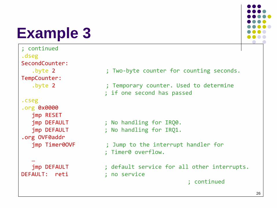
Example 3; continued.dsegSecondCounter:
.byte 2 ; Two-byte counter for counting seconds.TempCounter:
.byte 2 ; Temporary counter. Used to determine ; if one second has passed
.cseg
.org 0x0000 jmp RESET jmp DEFAULT ; No handling for IRQ0.jmp DEFAULT ; No handling for IRQ1.
.org OVF0addrjmp Timer0OVF ; Jump to the interrupt handler for
; Timer0 overflow.…jmp DEFAULT ; default service for all other interrupts.
DEFAULT: reti ; no service; continued
27
Example 3
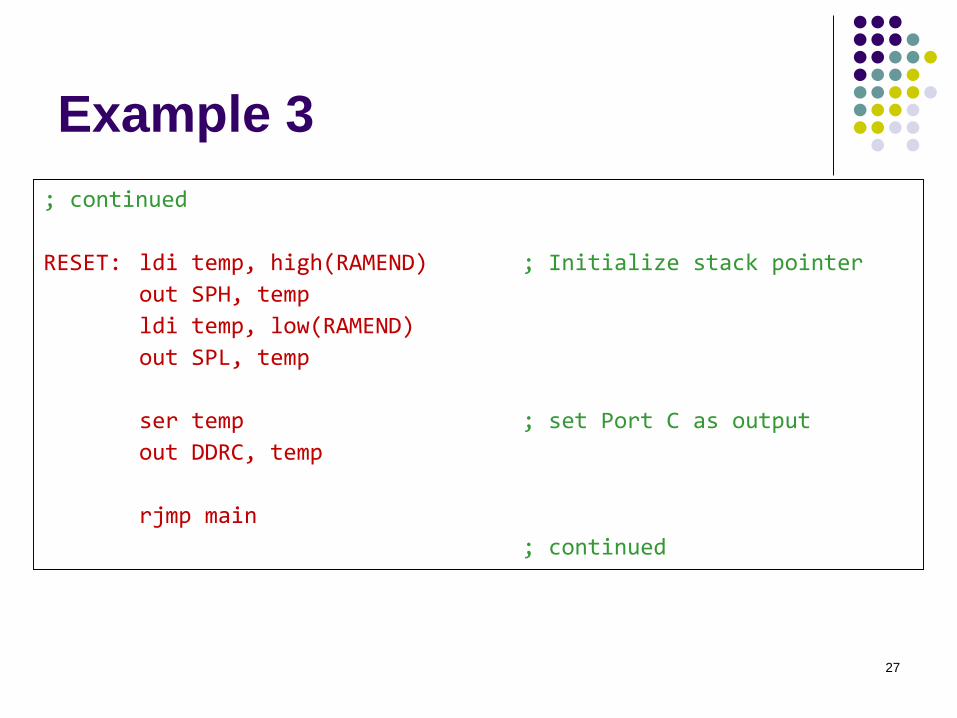
; continued
RESET: ldi temp, high(RAMEND) ; Initialize stack pointer
out SPH, temp
ldi temp, low(RAMEND)
out SPL, temp
ser temp ; set Port C as output
out DDRC, temp
rjmp main
; continued
28
Example 3
; continued
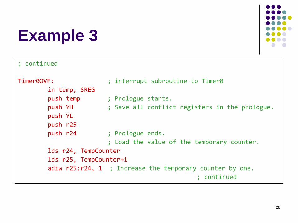
Timer0OVF: ; interrupt subroutine to Timer0
in temp, SREG
push temp ; Prologue starts.
push YH ; Save all conflict registers in the prologue.
push YL
push r25
push r24 ; Prologue ends.
; Load the value of the temporary counter.
lds r24, TempCounter
lds r25, TempCounter+1
adiw r25:r24, 1 ; Increase the temporary counter by one.
; continued
29
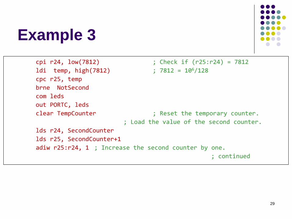
Example 3
cpi r24, low(7812) ; Check if (r25:r24) = 7812
ldi temp, high(7812) ; 7812 = 106/128
cpc r25, temp
brne NotSecond
com leds
out PORTC, leds
clear TempCounter ; Reset the temporary counter.
; Load the value of the second counter.
lds r24, SecondCounter
lds r25, SecondCounter+1
adiw r25:r24, 1 ; Increase the second counter by one.
; continued
30
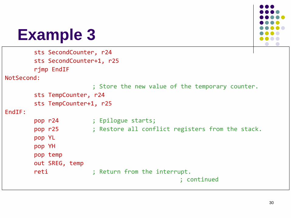
Example 3sts SecondCounter, r24
sts SecondCounter+1, r25
rjmp EndIF
NotSecond:
; Store the new value of the temporary counter.
sts TempCounter, r24
sts TempCounter+1, r25
EndIF:
pop r24 ; Epilogue starts;
pop r25 ; Restore all conflict registers from the stack.
pop YL
pop YH
pop temp
out SREG, temp
reti ; Return from the interrupt.; continued
31
Example 3
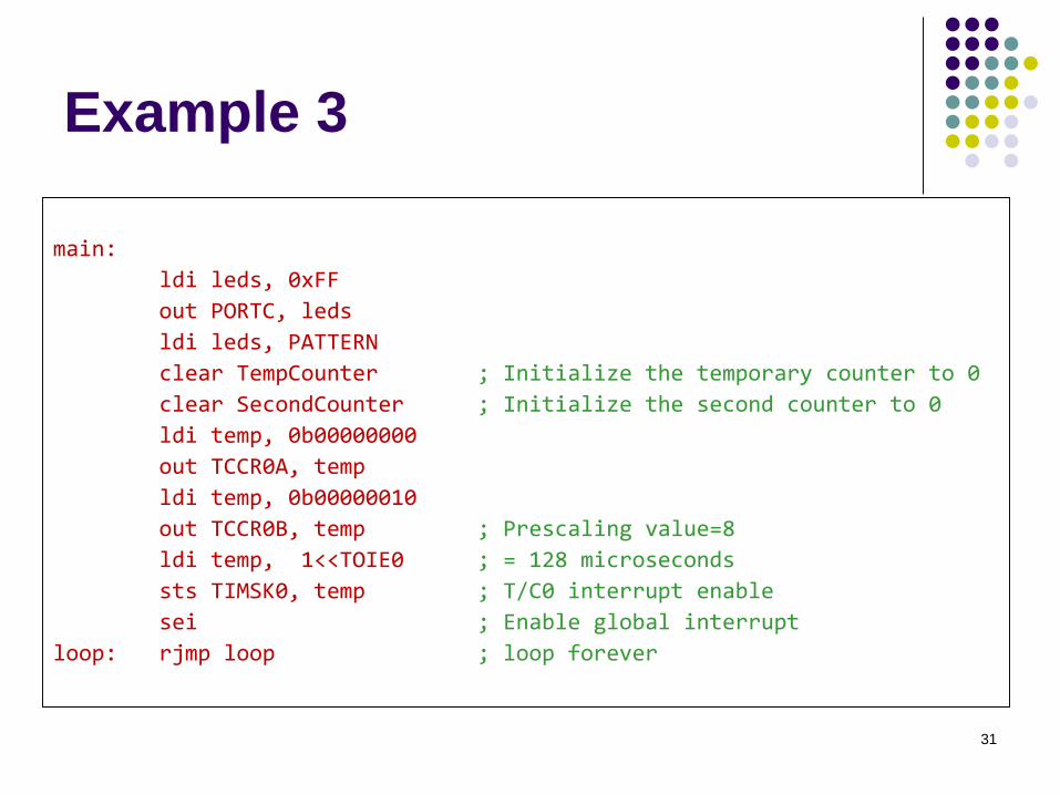
main:
ldi leds, 0xFF
out PORTC, leds
ldi leds, PATTERN
clear TempCounter ; Initialize the temporary counter to 0
clear SecondCounter ; Initialize the second counter to 0
ldi temp, 0b00000000
out TCCR0A, temp
ldi temp, 0b00000010
out TCCR0B, temp ; Prescaling value=8
ldi temp, 1<<TOIE0 ; = 128 microseconds
sts TIMSK0, temp ; T/C0 interrupt enable
sei ; Enable global interrupt
loop: rjmp loop ; loop forever
32
Reading Material
Chapter 8: Interrupts and Real-Time Events.
Microcontrollers and Microcomputers by
Fredrick M. Cady.
Mega2560 Data Sheet.
External Interrupts.
Timer0
33
Homework
1. What do you need to do to set up an Timer0
Output Compare Match Interrupt?
34
Homework
2. Based on the Example 1 in this week lecture
slides, implement a software interrupt such
that when there is an overflow in the counter
that counts the number of LED toggles, all
LEDs are turned on.