Embed Size (px)
Citation preview

Interrogation and Mitigation of Polarization Effects for Standard and
Birefringent FBGs Selwan K. Ibrahim*a, Jan Van Roosbroeckb, John A. O’Dowda, Bram Van Hoeb, Eric Lindnerbc,
Johan Vlekkenb, Martin Farnana, Devrez M. Karabacakad, Johannes M. Singerad aFAZ Technology Ltd., 9c Beckett Way, Park West Business Park, Dublin 12, Ireland;
bFBGS International, Bell Telephonelaan 2H, 2440 Geel, Belgium; cFBGS Technologies GmbH, Winzerlaer Straße 2, 07745 Jena, Germany;
dFugro Technology BV, Veurse Achterweg 10, 2264 SG Leidschendam, The Netherlands
ABSTRACT
Optical sensors based on Fiber Bragg Gratings (FBGs) are used in several applications and industries. Several inscription
techniques and types of fibers can be used. However, depending on the writing process, type of fiber used and the
packaging of the sensor a Polarization Dependent Frequency Shift (PDFS) can often be observed with polarized tunable
laser based optical interrogators. Here we study the PDFS of the FBG peak for the different FBG types. A PDFS of
<1pm up to >30pm was observed across the FBGs. To mitigate and reduce this effect we propose a polarization
mitigation technique which relies on a synchronous polarization switch to reduce the effect typically by a factor greater
than 4. In other scenarios the sensor itself is designed to be birefringent (Bi-FBG) to allow pressure and/or simultaneous
temperature and strain measurements. Using the same polarization switch we demonstrate how we can interrogate the
Bi-FBGs with high accuracy to enable high performance of such sensors to be achievable.
Keywords: Fiber optics, fiber Bragg gratings, fiber sensor, sensor interrogation, birefringence, polarization maintaining
fiber, polarization dependent frequency shift
1. INTRODUCTION
Fibre Bragg Grating (FBG) sensors [1-4] can be interrogated using different techniques (e.g. tunable/swept laser source
with direct detection, broadband source with a spectrometer, phase/interferometric detection) where the overall
performance depends on the combination of the interrogator and FBG sensor used. FBGs interrogated with polarized
frequency swept sources (e.g. polarized tunable lasers) could suffer from polarization dependent frequency shift (PDFS)
[5-6] which could be typically sub pm and up to 40pm. PDFS in FBG sensors is due to inherent birefringence in the FBG
due to the fiber or due to transversal strain applied on the FBG during mounting/packaging of the sensor.
The PDFS is unwanted because it can significantly contribute to the measurement error. It can cause drifts in the FBG
sensor for long term static applications and it can cause erroneous temperature or strain readings. Typically FBGs have a
10pm/°C temperature sensitivity. Therefore, a 30pm wavelength shift due to PDFS for example could cause a 3°C error
in the temperature measurement. An obvious way to reduce the PDFS is to use passive de-polarizers (e.g. Lyot
depolarizer) which are compatible with wide linewidth tunable lasers and broadband sources commonly used with a
direct detection photo-receivers or a spectrometer to form an optical interrogator. However for high precision
applications, narrow linewidth polarized tunable lasers are typically used to provide better resolution measurements. But
for such narrow linewidth tunable lasers, passive de-polarizers are not practical due to the long length of fiber required
[6]. Alternative ways to mitigate the PDFS is to use active polarization controllers, polarization switches or polarization
scramblers while maintaining the high precision measurements provided by narrow linewidth tunable laser based optical
interrogator systems.
Optical sensors based on Fiber Bragg Gratings (FBGs) are used in several applications and industries. Several inscription
techniques and types of fibers can be used. The standard FBG inscription process involves stripping/re-coating the fiber
and using a UV source and phase mask allowing the control of the FBG shape and characteristics [2]. However the
stripping/re-coating process limits the maximum strain that could be applied to the FBG. Draw tower grating (DTG)
enables the inscription of the grating during the fiber drawing process which avoids stripping the coating enabling higher
tensile strength for the sensor [4]. Also femtosecond lasers can be used to inscribe FS-FBGs using point-by-point, line-
by-line or phase mask inscription techniques which enable FBGs to operate at high temperature [7, 8]. However the side
Fiber Optic Sensors and Applications XIII, edited by Eric Udd, Gary Pickrell, Henry H. Du, Proc. of SPIE Vol. 9852, 98520H · © 2016 SPIE · CCC code: 0277-786X/16/$18 · doi: 10.1117/12.2223002
Proc. of SPIE Vol. 9852 98520H-1
Downloaded From: http://proceedings.spiedigitallibrary.org/ on 05/27/2016 Terms of Use: http://spiedigitallibrary.org/ss/TermsOfUse.aspx

effect of the writing process, type of fiber used and the packaging of the sensor highlights a polarization dependency
which could be observed with polarized tunable laser based optical interrogators. However for certain applications, the
FBGs are intended to be birefringent by inscribing them on birefringent fibers (Bi-FBG), such as polarization
maintaining FBGs (PM-FBG) [9-11] and micro-structured FBGs (MS-FBG) [12-13].
Standard FBGs are sensitive to both strain and temperature. In order to measure one parameter independently from the
other, an extra FBG would be required. For absolute strain measurements for example, one FBG will measure
simultaneously strain and temperature, while another FBG placed closely to the first one and isolated from strain will be
used for temperature measurement and compensation. This compensation will be limited by the mechanical restrictions
on co-locating and isolating the sensors, sensor drifts and the absolute measurement performance of the instrument.
Furthermore, the use of an additional FBG for compensation purposes often results in loss of effectively usable optical
bandwidth due to the required spectral gaps because of the manufacturing tolerances on the spectral positioning of two
reflective gratings. Additionally, use of a second grating can incur additional manufacturing costs. On the other hand, Bi-
FBGs such as PM-FBG sensors can provide strain‐independent temperature measurements and self-compensating strain
measurements without a requirement for an extra temperature FBG, while MS-FBG sensors can provide
temperature‐independent pressure measurements without a requirement for an extra FBG. In both of these birefringent
sensors, two reflection peaks corresponding to two orthogonal polarizations (i.e. slow and fast axis) are measured. The
wavelength spacing between those peaks contains temperature information for PM-FBG sensors and pressure
information for MS-FBG sensors. However, in both fibers, the induced relative wavelength shifts between the two
polarization-dependent reflection peaks resulting due to external effects (e.g. pressure, temperature, strain) may be
relatively small. As such, both birefringent sensing fibers generally require very high precision monitoring of their
polarization-dependent reflection wavelengths to enable sensing applications with the desired accuracy.
To measure the two peaks with a polarized swept source interrogator, an extra polarization controller/scrambler would be
required to either scramble the polarization or track the polarization at high speed. The speed of the polarization
controller will depend on the laser tuning rate, sweep rate, and interrogator receiver bandwidth. For tuning rates
>0.1pm/ns and receiver BW >20MHz, the polarization scrambler speed needs to be in the order of hundreds of MHz
which means high speed, high cost, multi-wave plate polarization controllers would be required. In addition to that in
order to resolve the wavelength spacing between the two orthogonal responses/peaks, high accuracy and high resolution
measurements are also required.
In this paper we evaluate the PDFS observed on three different type of FBGs (standard FBG, DTG, and FS-FBG) [2, 4,
7, 8] supplied from different vendors. The PDFS was mitigated (reduced) by using polarization mitigation scheme based
on a polarization switch synchronous with the tunable laser interrogator sweep. The same system was used to interrogate
birefringent optical sensors Bi-FBG (PM-FBG and MS-FBG) by measuring the two orthogonal FBG responses with high
precision.
2. TUNABLE LASER INTERROGATOR OPERATION
The FAZ Technology (FAZT) tunable laser based optical interrogator platform (V4 and I4) is based on a semiconductor
tunable laser diode that has no moving parts delivering high level of reliability and accuracy in addition to a power and
wavelength reference section that includes several fine and coarse periodic wavelength references (e.g. Etalon). The
main basic building blocks of the interrogator are shown in figure 1 below consisting of the transmitter section,
polarization controller (switch/scrambler), passive optics section which interfaces between the fiber sensor array and the
receiver section, all connected and controlled by a computer on board (COB) which transfers the data to the end
user/client via a high speed data communication link. The polarization switch/scrambler is connected between the laser
output and the FBG channels for polarization control and polarization dependent frequency shift (PDFS) mitigation.
The laser in the V4/I4 interrogator scans the C-band (40nm) at a rate of 1kHz (tuning rate of 0.1pm/ns) and the output
power is split over four separate channels (typically +3dBm/channel) with the minimum detectable power (noise floor) at
the receive end <-40dBm. The received reflected signal is sampled with 1pm resolution. The four separate fiber optic
channels can each simultaneously measure up to 30 FBG sensors @1kHz sample rate (120 sensors in total).
This is achieved by implementing the FBG peak processing algorithms in hardware on a field programmable gate array
(FPGA) connected internally to a computer on board (COB) unit which enables streaming data over a 1Gbit/s Ethernet
connection for the V4, and 100Mbit/s Ethernet connection for the I4.
Proc. of SPIE Vol. 9852 98520H-2
Downloaded From: http://proceedings.spiedigitallibrary.org/ on 05/27/2016 Terms of Use: http://spiedigitallibrary.org/ss/TermsOfUse.aspx

...........::<:.. High Speed DataCommunications Sub - System
COB
TransmitterPolarization OpticsController (Rx and ref.)
:
Receiver Sensor Array
Figure 1. Block diagram of the FAZT tunable laser interrogator
The highly repeatable tunable laser combined with precise wavelength referencing enables long term high precision
measurements (DC) (precision <30/100fm (1σ) (V4/I4) measured by tracking HCN Gas Cell line P10 [1549.7305]
>10hours [5, 14]). The V4/I4 long term absolute accuracy specified over the life time of the product (bias/deviation from
the true value using a HCN gas cell) over the operating target temperature (0-55°C) and wavelength range (C-band) is
<1pm. This may be improved to <0.5pm when operating at room temperature for both V4/I4. For dynamic
measurements (AC), a repeatability of <25/50fm (1σ) @1kHz sample rate (<40seconds) is achieved for the V4/I4 which
defines the noise floor in the frequency domain [5].
3. FBG POLARIZATION SENSITIVITY MITIGATION
The FAZ interrogator uses a laser with a polarized output and includes the option to interrogate and mitigate polarization
effects for different types of sensors using either a 2 state polarization switch (Pol. SW), a multi-state (>2) polarization
switch, or a high speed scrambler which could be required for certain applications. Here we study the birefringence
effect on the fiber/sensor by measuring the PDFS of the FBG peak for the different FBG types. A PDFS of sub pm up to
>30pm was observed across the FBGs. To mitigate and reduce this effect we propose a polarization mitigation technique
which relies on a synchronous polarization switch to reduce the PDFS effect by a typical factor between 4 and 10
depending on the FBG characteristics and its birefringence.
Figure 2 (left) below shows a setup consisting of an I4 four channel interrogator connected to 3 types of FBGs from
different vendors (standard grating (FBG), draw tower grating (DTG), and femtosecond inscribed grating (FS-FBG).
Several standard FBGs (strip/re-coat) have been tested from different vendors and the PDFS varied between sub pm to
<5pm. The FBG vendor with the FBG having the lowest measured PDFS was selected for the standard FBG type test.
The specifications of all the FBGs and their spectral shape are shown in figure 2 (right) where the full width half
maximum (FWHM) was 0.05nm, 0.1nm, and 0.5nm for the FBG, DTG, and FS-FBG, respectively. As for the grating
length, it was approximately 28mm, 8mm, and 4mm for the FBG, DTG, and FS-FBG, respectively based on
manufacturer specification. It should be noted for some applications the shorter grating is more desirable to enable the
packaging and mounting of the FBG in certain transducer designs.
Proc. of SPIE Vol. 9852 98520H-3
Downloaded From: http://proceedings.spiedigitallibrary.org/ on 05/27/2016 Terms of Use: http://spiedigitallibrary.org/ss/TermsOfUse.aspx
r MIIIMMMENNEMwIMIM1===1=11111M=1=1====1111=MOiMIIMI=======i1M111==MI=1=1MIMMIIMa=1=MMIMMI=I8=MIIMOMIMIENIMMdI=aMM=====1=11i1=1=-111=-EMINE=1=1MNIMMEME=lMIMIl=ME11==M111=M=IIIMEM=MNIM=1=====l1=M11=11M=IMII=M=MIIIMIMIllil===111=11===11=11M=IMEMINE=IMMEI=M111=MI_ÓinPIE1===1 =
Standard FBGX 1550nmLL28mmR >15%
FWHM- 0.05nm
PolarizationController/Polarimeter
1x4 Splitterand
4 x Circulators(4 FBG Channels)
DTG
X-1534nmL-8mmR>20%
FWHM-0.1nm
{ FS-FBG
A-1556.2nm"L-4mmR>SO%
FWHM-O.Snm
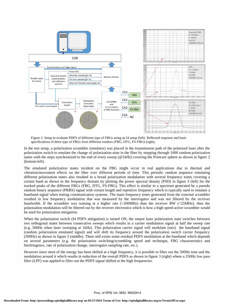
Figure 2. Setup to evaluate PDFS of different type of FBGs using an I4 setup (left). Reflected response and basic
specifications of three type of FBGs from different vendors (FBG, DTG, FS-FBG) (right).
In the test setup, a polarization scrambler (emulator) was placed in the transmission path of the polarized laser after the
polarization switch to emulate the change of polarization state in the fiber by stepping through 1000 random polarization
states with the steps synchronized to the end of every sweep (@1kHz) covering the Poincare sphere as shown in figure 2
(bottom-left).
The emulated polarization states incident on the FBG might occur in real applications due to thermal and
vibration/movement effects on the fiber over different periods of time. This periodic random sequence emulating
different polarization states also resulted in a broad polarization modulation with several frequency tones covering a
certain band as shown in the frequency domain by plotting the power spectral density (PSD) in figure 3 (left) for the
tracked peaks of the different FBGs (FBG, DTG, FS-FBG). This effect is similar to a spectrum generated be a pseudo
random binary sequence (PRBS) signal with certain length and repetitive frequency which is typically used to emulate a
baseband signal when testing communication systems. The main frequency tones generated from the external scrambler
resulted in low frequency modulation that was measured by the interrogator and was not filtered by the receiver
bandwidth. If the scrambler was running at a higher rate (>200MHz) than the receiver BW (<25MHz), then the
polarization modulation will be filtered out by the receiver electronics which is how a high speed active scrambler would
be used for polarization mitigation.
When the polarization switch (I4 PDFS mitigation) is turned ON, the output laser polarization state switches between
two orthogonal states between consecutive sweeps which results in a carrier modulation signal at half the sweep rate
(e.g. 500Hz when laser sweeping at 1kHz). This polarization carrier signal will modulate (mix) the baseband signal
(random polarization emulated signal) and will shift its frequency around the polarization switch carrier frequency
(500Hz) as shown in figure 3 (middle). There still exists some residual PDFS modulation at the baseband which depends
on several parameters (e.g. the polarization switching/scrambling speed and technique, FBG characteristics and
birefringence, rate of polarization change, interrogator sampling rate, etc.).
However since most of the energy has been shifted at a high frequency, it is possible to filter out the 500Hz tone and the
modulation around it which results in reduction of the overall PDFS as shown in figure 3 (right) where a 250Hz low pass
filter (LPF) was applied to filter out the PDFS signal shifted at the high frequencies.
Proc. of SPIE Vol. 9852 98520H-4
Downloaded From: http://proceedings.spiedigitallibrary.org/ on 05/27/2016 Terms of Use: http://spiedigitallibrary.org/ss/TermsOfUse.aspx

Polarization scrambling(Low Freq. Broadband Pol. Modulation)
FBGDTG
FS-FBG
!.aMf4i,yR'i1,dAlwh, ';.if6{ Idli..,
Polarization scrambling + Polarization SW4 Polarization Modulation 4 Freq. Shift @500Hz
Reduction in low freq. pol. noise Polarization scrambling+ Polarization SW+ 250Hz LPF (filters out high freq. Pol. mod.)
Figure 3. PSD response of the tracked FBG peaks (FBG, DTG, FS-FBG) when the pol. scrambler is ON, pol. SW OFF
(left), pol. scrambler is ON, pol. SW ON (middle), and pol. scrambler is ON, pol SW ON, 250Hz LPF is ON (right).
In the time domain the concept of PDFS mitigation can be viewed as changing the polarization state incident on the FBG
and measuring the PDFS (interrogating the polarization sensitivity PDFS of the FBG) and averaging out the effect (by
averaging several scans or using a digitally implemented LPF) as shown in figure 4 below.
Figure 4. Peak tracking of the three different FBGs (FBG, DTG, FS-FBG) with a 250Hz LPF applied to all data when the
pol. scrambler (emulator) is turned OFF and pol. mitigation OFF (left), pol. scrambler (emulator) is turned ON and pol.
mitigation OFF (middle), pol. scrambler (emulator) is turned ON and pol. mitigation ON (right).
It can be noted from figure 4 that the FBG had the lowest PDFS <0.1pm peak-to-peak (p-p), the DTG had PDFS~7.7pm
(p-p), while the FS-FBG had the highest PDFS~34.4pm (p-p) without polarization mitigation. When the polarization
mitigation was turned ON the PDFS p-p values dropped down within the noise level/drift of the measurement for the
Proc. of SPIE Vol. 9852 98520H-5
Downloaded From: http://proceedings.spiedigitallibrary.org/ on 05/27/2016 Terms of Use: http://spiedigitallibrary.org/ss/TermsOfUse.aspx

ReceiverReferenceSection
EMIPolarization
SwitchCirculatoror Coupler
35 /30 / FOG DT6 FSFB6
25 /20V
15
a 10
5 0.1166 0.1011 0.18348
0
34.4045
7.72146.2019
0.168 0.10261.1251
Scrambler OFF + Pol SW OFF Scrambler ON + PoI SW Off Scrambler ON + PoI SW ON
standard FBG, and dropped down to 1.125pm, and 6.2pm for both the DTG and FS-FBG respectively as shown in figure
5. The PDFS reduction factor varies and depends on several variables such as the polarization mitigation technique used,
type and shape of FBG, birefringence, speed of polarization change, averaging, etc.
Figure 5. Measured PDFS (peak-to-peak) of the three different FBGs (FBG, DTG, FS-FBG) with a 250Hz LPF applied to
all data when the pol. scrambler (emulator) is turned OFF and pol. mitigation OFF (left), pol. scrambler (emulator) is turned
ON and pol. mitigation OFF (middle), pol. scrambler (emulator) is turned ON and pol. mitigation ON (right).
4. BIREFRINGENT FBG INTERROGATION
In the previous section we have demonstrated how the PDFS induced due to the FBG birefringence can be mitigated by
measuring the PDFS at high speed and filtering out the effect. However in other scenarios the sensor itself can be
intentionally designed to be birefringent (Bi-FBG) to allow simultaneous pressure and temperature or temperature and
strain measurements [9-13]. Using the same polarization switch used for PDFS mitigation, we demonstrate how we can
interrogate the polarization effects with high accuracy to enable high performance of such sensors to be achievable.
Figure 6 shows a basic schematic diagram illustrating a simple single channel of a FAZT tunable laser interrogator
(figure 6 (left)) used to interrogate a Bi-FBG sensor with the polarization switch and the spectral response of a PM-FBG
(figure 6 (right)) [10].
Figure 6. Basic schematic diagram for a single channel FAZT interrogator showing the detection of two birefringent peaks.
When birefringent FBGs are interrogated with a polarized tunable laser, the reflected spectrum will be dependent on the
incident state of polarization on the FBG as shown in figure 7 (left) where either one of the Bi-FBG peaks is detected (a,
b) or both (c). For high accuracy interrogation however, both peaks should be detected simultaneously and preferably
with maximum power level. The polarization state in the fiber also tends to change with temperature and movement of
the fiber and so in practice it is difficult to control the incident state of polarization.
To overcome these issues, one could use several approaches. The most obvious one is to depolarize the optical source,
either via a high speed scrambler or via a passive depolarizer. But these solutions are not always easy. High speed
scramblers are required for high sweep rates and these are difficult to find. And the possibility to use a passive
depolarizer depends on the coherence length of the laser source and for long coherence lengths this becomes unpractical.
Proc. of SPIE Vol. 9852 98520H-6
Downloaded From: http://proceedings.spiedigitallibrary.org/ on 05/27/2016 Terms of Use: http://spiedigitallibrary.org/ss/TermsOfUse.aspx

An alternative approach is to use a 2-state polarization switch in order to change the polarization state in synchronization
with the laser sweep, figure 7 (right). The two orthogonal reflection responses of the FBG are detected and the spectra
are averaged. The power levels of both peaks in the averaged spectra will be less susceptible to polarization changes and
so accurate peak detection can be performed. The peak wavelength position of the FBG responses in addition to the
wavelength difference between the two peaks contains all the required sensor information. Typically the spacing between
the peaks is in the order of 0.5 to 2nm and the temperature sensitivity for the wavelength difference of PM-FBGs are
lower than standard FBGs. In order to achieve high resolution measurements with low sensitivity sensors, accurate
interrogation system with high precision is required.
Figure 7. Reflected response from a Bi-FBG for different static polarization states (left), basic operation of the polarization
switch in synchronization to the laser sweep to enable spectrum averaging and double peak detection (right).
One limitation of the above proposed polarization switch approach used on the I4 interrogator is that the averaging needs
to be done on spectrum level at a reduced scan rate (4 Hz for 4 channels or 16 Hz single channel). Therefore, high speed
measurements are not possible with this measurement mode due to the high throughput required for the spectral data on
the I4 interrogator (40000 wavelength data points × scan rate throughput is required for the full 40nm@1pm resolution
spectrum data capture). In order to be able to measure at high scan rates, the spectral averaging and peak processing will
need to be implemented in the interrogator unit.
An alternative approach to support high speed sampling without requiring spectral averaging was also developed. In this
approach, the path between the interrogator and Bi-FBG needs to be fully polarization maintaining (PM) and should be
aligned properly with the polarization state of the source. In this case, on every sweep only one of the peaks can be
detected at full power and it will alternate with the other peak depending on the state of the polarization switch.
Therefore peak processing can be applied before the spectrum averaging at high speed, with the on board peak
processing algorithm contained in the FPGA. This method of interrogation was used to demonstrate simultaneous high
speed strain and temperature measurements of a PM-FBG. Figure 8 (top) shows two tracked peaks corresponding to the
two orthogonal responses (λ1, λ2) where the data was re-sampled to 250Hz to enable the delay between the two detected
orthogonal peaks to be compensated. During the measurement, different levels of strain were applied 3 times at the start
to the PM-FBG, then followed by heating the PM-FBG twice, and finally cooling the PM-FBG as shown in figure 8
(top). Figure 8 (bottom) shows the difference in wavelength for the two detected orthogonal peaks (Δλ1, Δλ2) with
respect to their reference wavelengths (at room temperature and no strain applied).
Proc. of SPIE Vol. 9852 98520H-7
Downloaded From: http://proceedings.spiedigitallibrary.org/ on 05/27/2016 Terms of Use: http://spiedigitallibrary.org/ss/TermsOfUse.aspx

Figure 8. Tracked peaks corresponding to the two orthogonal responses (λ1, λ2) of a PM-FBG exposed to strain, heating and
cooling with scan rate =250Hz (top), wavelength shift Δλ of the orthogonal peaks with respect to their reference λ (bottom).
The response of the individual wavelengths λ1, λ2 to ε and T variations is very similar to the response for regular
DTG/FBGs but there will be slight differences in sensitivity between the two peaks. Mathematically, we get a set of two
equations that relate λ1, λ2 to ε and T with coefficients that are slightly different [10, 11] as shown in equations 1 and 2.
λ1 - λ10 = a ΔT + b Δɛ (1)
λ2 - λ20 = c ΔT + d Δɛ (2)
In equations (1) and (2), λ1 is the low wavelength peak and λ2 the high wavelength peak for the PM-DTG. The a, b, c and
d parameters are the sensitivity parameters for strain (Δɛ) and temperature (ΔT) and λ10 and λ20 are the reference
wavelengths at known strain and temperature. For the PM-FBG used for the experiment the sensitivities values where:
a = 13.37 pm/°C, b = 1.175 pm/µɛ, c = 12.6 pm/°C, and d = 1.19 pm/µɛ. The small differences in sensitivity originate
predominantly from the temperature dependence of the stress birefringence, and the peak separation can be regarded as a
direct measure for it. The sensitivity of the peak separation is a key parameter for the decoupling between ε and T. The
inverse relation can be used to directly calculate the decoupled strain and temperature as shown in equations 3 and 4.
ΔT= (dΔλ1 - bΔλ2)/D (3)
Δɛ = (aΔλ2 - cΔλ1)/D (4)
Where D = ad-bc is the determinant of the matrix. In this way, all cross sensitivity between strain and temperature should
be completely removed as shown in figure 9 where the temperature measurements is shown on the top and the strain
measurements are shown on the bottom.
Proc. of SPIE Vol. 9852 98520H-8
Downloaded From: http://proceedings.spiedigitallibrary.org/ on 05/27/2016 Terms of Use: http://spiedigitallibrary.org/ss/TermsOfUse.aspx

ReferenceSection
Polarization5 ,: itch
Figure 9. Simultaneous measurement of temperature (Top) and strain (bottom) for the PM-FBG showing the different times
where the strain, heating, and cooling was applied to the sensor.
Another example of a Bi-FBG is a micro-structured FBGs (MS-FBG) [12, 13] that could be used for temperature
independent pressure measurements is shown in figure 10 using the same setup and polarization interrogation scheme
previously described.
Figure 10. Basic schematic diagram for a single channel FAZT V4 interrogator showing the detection of two birefringent
peaks of a MS-FBG pressure sensor installed in a pressure vessel.
Proc. of SPIE Vol. 9852 98520H-9
Downloaded From: http://proceedings.spiedigitallibrary.org/ on 05/27/2016 Terms of Use: http://spiedigitallibrary.org/ss/TermsOfUse.aspx

1
1
sta
aaaaa aaaaa
f)
The pressure was varied between 0 - 5 - 0 bar in 1 bar steps using a pressure controller while the spectrum was captured
at 100Hz with 1pm resolution using a FAZT V4 interrogator and then averaged down to 5Hz with the polarization switch
turned ON to guarantee two orthogonal peaks are detected. Figure 11 shows the peak tracking of one of the orthogonal
peaks across the 0-5-0 bar pressure scan range. A first observation are spikes at every pressure step. These spikes are
originating from the temperature changes that coincide with the rapid pressure changes for each pressure step (gas law at
constant volume), see figure 11 (left). The heat that is generated by the pressure change rapidly dissipates and this
explains why the signal quickly restores to its original level. It can also be observed that each increasing (decreasing)
temperature step is followed by a small temperature decrease (increase). This comes from the same effect in combination
with the pressure controller correcting for a small pressure overshoot (undershoot). The next observation is that the start
and end point of the measurement @0bar are at different positions. Most likely this comes from a small change in
temperature (< 0.2°C) on the sensor, see figure 11 (right).
Figure 11. Peak tracking of one of the orthogonal peaks (λ1) of the MS-FBG sensor showing the temperature dependency at
the start and end of measurement @0bar.
The two orthogonal peaks tracked are shown in figure 12 (top), while the wavelength separation between the orthogonal
peaks are shown in figure 12 (bottom) highlighting the strong correlation between the orthogonal peak wavelength
spacing and the applied pressure. The wavelength difference between the detected peaks varied by -1pm for every 1 bar
step. The standard deviation/noise of a 100 scans @5Hz were measured to be ~40fm which represents the minimum
detectable change in delta wavelength due to pressure change. Neither the temperature spikes nor the temperature drift at
0 bar was observed on the delta wavelength between the two orthogonal peaks, which clearly indicates the ability of the
MS-FBG to separate temperature from pressure.
Figure 12. Peak tracking of the two orthogonal peaks (λ1, λ2) of the MS-FBG sensor (top), wavelength difference between
the two orthogonal peaks when the pressured was changed between 0 - 5 - 0 bar in 1 bars steps.
Proc. of SPIE Vol. 9852 98520H-10
Downloaded From: http://proceedings.spiedigitallibrary.org/ on 05/27/2016 Terms of Use: http://spiedigitallibrary.org/ss/TermsOfUse.aspx

A similar MS-FBG sensor was also tested with an I4 using the same interrogation technique but over a narrow range of 1
bar and with smaller steps of 0.1 bar and 0.2 bar as shown in figure 13 top, and bottom respectively.
Figure 13. Peak tracking of the two orthogonal peaks (λ1, λ2) of the MS-FBG sensor over a 1 bar range using 0.1 bar steps
(top), and 0.2bar steps (bottom).
5. CONCLUSION
We have shown that different type of FBGs (FBG, DTG, FS-FBG) supplied from different vendors exhibit different
levels of Polarization Dependent Frequency Shift when used with a polarized tunable laser interrogator. We have
demonstrated that the PDFS can be mitigated/reduced in the sensors by applying a polarization mitigation technique
using a polarization switch synchronized to the sweep. The same polarization control and interrogation technique was
also used to demonstrate the interrogation of birefringent FBGs such as PM-FBG sensors to simultaneously measure
strain and temperature and MS-FBG sensors to enable temperature independent pressure measurements.
ACKNOWLEDGMENTS
The authors would like to thank all the FAZ Technology engineering team. This work was supported by the ESA GSTP
program.
REFERENCES
[1] Kersey, A.D., Davis, M.A., Patrick, H.J., LeBlanc, M., Koo, K.P., Askins, C.G., Putnam, M.A. and Friebele, E.J.,
“Fiber grating sensors,” IEEE Journal of Lightwave Technology, 15(8), 1442-1463, (1997).
[2] Hill, K.O. and Meltz, G., “Fiber Bragg grating technology fundamentals and overview,” IEEE Journal of Lightwave
Technology, 15(8), 1263-1276 (1997).
[3] Kinet, D., Mégret, P., Goossen, K.W., Qiu, L., Heider, D. and Caucheteur, C., “Fiber Bragg grating sensors toward
structural health monitoring in composite materials: Challenges and solutions,” Sensors, 14(4), 7394-7419, (2014).
[4] Lindner, E., Mörbitz, J., Chojetzki, C., Becker, M., Brückner, S., Schuster, K., Rothhardt, M., Willsch, R. and
Bartelt, H., “Tailored draw tower fiber Bragg gratings for various sensing applications,” Asia Pacific Optical
Sensors Conference, 835112-835112, (2012).
Proc. of SPIE Vol. 9852 98520H-11
Downloaded From: http://proceedings.spiedigitallibrary.org/ on 05/27/2016 Terms of Use: http://spiedigitallibrary.org/ss/TermsOfUse.aspx

[5] Ibrahim, S.K., O'Dowd, J., McCue, R., Honniball, A. and Farnan, M., “Design Challenges of a High Speed Tunable
Laser Interrogator for Future Spacecraft Health Monitoring,” CLEO: Applications and Technology, ATu1M-3,
(2015).
[6] Kang, M.S., Yong, J.C. and Kim, B.Y., “Suppression of the polarization dependence of fiber Bragg grating
interrogation based on a wavelength-swept fiber laser,” Smart materials and structures, 15(2), 435, (2006).
[7] Mihailov, Stephen J., "Fiber Bragg grating sensors for harsh environments," Sensors, 12 (2), 1898-1918, 2012.
[8] Liao, C.R. and Wang, D.N., “Review of femtosecond laser fabricated fiber Bragg gratings for high temperature
sensing,” Photonic Sensors, 3(2), 97-101, (2013).
[9] Chen, G., Liu, L., Jia, H., Yu, J., Xu, L., and Wang, W., “Simultaneous strain and temperature measurements with
fiber Bragg grating written in novel Hi-Bi optical fiber,” IEEE Photonics Technology Letters, 16(1), 221-223,
(2004).
[10] Van Roosbroeck, J., Ibrahim, S.K., Lindner, E., Schuster, K. and Vlekken, J., “Stretching the Limits for the
Decoupling of Strain and Temperature with FBG based sensors,” International Conference on Optical Fibre Sensors
(OFS24), 96343S-96343S, (2015).
[11] Ferreira, L.A., Santos, J.L., Farahi, F., Araujo, F.M., “Simultaneous measurement of strain and temperature using
interferometrically interrogated fiber Bragg grating sensors,” Opt. Eng. 39(8), 2226-2234 (2000).
[12] Berghmans, F., Geernaert, T., Baghdasaryan, T. and Thienpont, H., “Challenges in the fabrication of fibre Bragg
gratings in silica and polymer microstructured optical fibres,” Laser & Photonics Reviews, 8(1), 27-52, (2014).
[13] Sulejmani, S., Sonnenfeld, C., Geernaert, T., Mergo, P., Makara, M., Poturaj, K., Skorupski, K., Martynkien, T.,
Statkiewicz-Barabach, G., Olszewski, J. and Urbanczyk, W., “Control over the pressure sensitivity of Bragg grating-
based sensors in highly birefringent microstructured optical fibers,” IEEE Photonics Technology Letters, 24(6), 527-
529, (2012).
[14] Gilbert, S.L., Swann, W.C. and Wang, C.M., “Hydrogen cyanide H13C14N absorption reference for 1530 nm to
1565 nm wavelength calibration–SRM 2519a,” NIST special publication, 260, p.137, (2005).
Proc. of SPIE Vol. 9852 98520H-12
Downloaded From: http://proceedings.spiedigitallibrary.org/ on 05/27/2016 Terms of Use: http://spiedigitallibrary.org/ss/TermsOfUse.aspx