Embed Size (px)
Citation preview
102 rue Etienne Dolet Tel: 33 1 40 92 79 3092240 MALAKOFF, France Fax: 33 1 46 55 62 65Web Site: www.eurocae.eu Email: [email protected]
Interoperability Standards for VoIP ATM Components
Part 1: Radio
ED-137 Part 1 “Month Year”
The European Organisation for Civil Aviation Equipment L’Organisation Européenne pour l’Equipement de l’Aviation Civile
© EUROCAE, 2009
Interoperability Standards for VoIP ATM Components
Part 1: Radio
ED-137 Part 1 “Month Year”
© EUROCAE, 2009
i
FOREWORD
1 The document ED-137 “Interoperability Standards for VoIP ATM Components” was
prepared by EUROCAE Working Group 67 and was accepted by the Council of EUROCAE on “Month Year”.
2 EUROCAE is an international non-profit making organisation. Membership is open to manufacturers and users in Europe of equipment for aeronautics, trade associations, national civil aviation administrations and non-European organisations. Its work programme is principally directed to the preparation of performance specifications and guidance documents for civil aviation equipment, for adoption and use at European and world-wide levels.
3 The findings of EUROCAE are resolved after discussion among its members and, where appropriate, in collaboration with RTCA Inc, Washington D.C. USA and/or the Society of Automotive Engineers (SAE), Warrendale, PA, USA through their appropriate committee.
4 The document represents “the minimum specification required for Manufacturers and Users to assure Interoperability between VoIP ATM Components”.
5 EUROCAE performance specifications are recommendations only. EUROCAE is not an official body of the European governments; its recommendations are valid statements of official policy only when adopted by a particular government or conference of governments.
6 Copies of this document may be obtained from:
EUROCAE 102 rue Etienne Dolet
92240 MALAKOFF France
Tel: 33 1 40 92 79 30 Fax: 33 1 46 55 62 65
Email: [email protected] Web Site: www.eurocae.eu
© EUROCAE, 2009
ii
TABLE OF CONTENTS CHAPTER 1 INTRODUCTION................................................................................................................ 1
1.1 BACKGROUND..................................................................................................................... 1 1.2 ED-137 PRESENTATION ..................................................................................................... 3 1.3 TERMINOLOGY FOR REQUIREMENTS, RECOMMENDATIONS AND OPTIONS............ 3
CHAPTER 2 RADIO COMMUNICATION MODEL.................................................................................. 5 2.1 DEFINITIONS........................................................................................................................ 5 2.2 PROTOCOL STACK ............................................................................................................. 8 2.3 BASIC PROTOCOL REQUIREMENTS ............................................................................... 8 2.4 MODES OF OPERATION ..................................................................................................... 9
2.4.1 Real time Transport Protocol (RTP) and Real time Transport Header Extension ........... 9 2.4.2 Connection init using SIP signalling protocol ................................................................... 9 2.4.3 SIP connections with separate Tx and RX Radio equipment ........................................ 10 2.4.4 SIP connections with different Radio equipment working in CLIMAX mode.................. 12
CHAPTER 3 SIGNALLING.................................................................................................................... 13 3.1 INTRODUCTION ................................................................................................................. 13 3.2 SESSION INITIATION PROTOCOL ................................................................................... 13
3.2.2 PROFILE STANDARD FOR THE USE OF SIP IN AN AGVN ....................................... 13 3.2.3 SUPPORTED REQUESTS ............................................................................................ 14 3.2.4 SUPPORTED RESPONSES.......................................................................................... 16 3.2.5 MESSAGE BODY (SDP)................................................................................................ 20
3.3 ADDRESS FORMAT........................................................................................................ 22 3.4 SIP CONNECTION FACILITIES ......................................................................................... 22
3.4.1 Basic call functionalities ................................................................................................. 22 3.4.2 AUDIBLE TONES........................................................................................................... 24 3.4.3 Call Set Up Procedure.................................................................................................... 24
CHAPTER 4 AUDIO.............................................................................................................................. 26 4.1 INTRODUCTION ................................................................................................................. 26 4.2 AUDIO SPECIFICATION..................................................................................................... 26
4.2.1 Audio Level..................................................................................................................... 26 4.2.2 Audio Quality .................................................................................................................. 26 4.2.3 Voice Coding .................................................................................................................. 28
4.3 GUIDELINES FOR SAMPLE-BASED AUDIO CODECS .................................................... 28 4.4 AUDIO CODECS................................................................................................................. 28
CHAPTER 5 RTP: REAL TIME PROTOCOL........................................................................................ 30 5.1 AUDIO STREAM USING RTP WITH HEADER EXTENSION ............................................ 30
5.1.1 Introduction..................................................................................................................... 30 5.1.2 Objectives of this section................................................................................................ 30 5.1.3 Basic System Topology.................................................................................................. 30
5.2 RTP/RTCP PROTOCOL DEFINITION................................................................................ 31 5.3 RTP HEADER ..................................................................................................................... 31 5.4 RTP-PAYLOAD TYPES COMPLIANT WITH RFC 3551 .................................................... 31
5.4.1 AUDIO CODECS............................................................................................................ 32 5.4.2 Profile specific items....................................................................................................... 32
5.5 INDEPENDENT ENCODING RULES FOR AUDIO ............................................................ 33 5.6 OPERATING RECOMMENDATIONS................................................................................. 33
5.6.1 Voice packetization ........................................................................................................ 33 5.6.2 Voice transmission performance.................................................................................... 33 5.6.3 Real time signals management and control ................................................................... 33 5.6.4 Class of Service (CoS) and Quality of Service (QoS) ................................................... 34
5.7 GUIDELINES FOR SAMPLE-BASED AUDIO CODECS .................................................... 35 5.8 AUDIO CODECS PAYLOAD TYPE .................................................................................... 36 5.9 PORT ASSIGNMENT.......................................................................................................... 36 5.10 RTP HEADER EXTENSION FOR RADIO APPLICATIONS............................................... 36
5.10.1 Principle of operations ................................................................................................. 36 5.10.2 RTP Header Extension description.............................................................................. 40 5.10.3 RTPTx Information field ............................................................................................... 41 5.10.4 RTPRx Information field............................................................................................... 44 5.10.5 Additional Features...................................................................................................... 45
© EUROCAE, 2009
iii
CHAPTER 6 .......................................................................................................................................... 49 6.1 Real Time Session Supervision .......................................................................................... 49
6.1.1 Introduction..................................................................................................................... 49 6.1.2 Signalling message types............................................................................................... 49 6.1.3 R2S Keep Alive Signalling Operation............................................................................. 49
ANNEX A REFERENCES ..................................................................................................................... 53 ANNEX B BEST SIGNAL SELECTION AND AUDIO LEVEL QUALITY INDEX RECEPTION ............ 55
B.1.1. Objectives of this Annex .............................................................................................. 55 B.1.2. BSS definition .............................................................................................................. 55 B.1.3. Architectures ................................................................................................................ 57
B.2. Quality Index Coding ........................................................................................................... 59 B.2.1. Parameters coding....................................................................................................... 59
B.3. Conclusion........................................................................................................................... 61 ANNEX C CLIMAX CONSIDERATIONS............................................................................................... 62
C.1. Purposes.............................................................................................................................. 62 C.2. Principle ............................................................................................................................... 62 C.3. Issues raised ....................................................................................................................... 62 C.4. Echo effects......................................................................................................................... 62 C.5. SIGNAL FADING................................................................................................................. 62 C.6. Implementation precautions ................................................................................................ 63 C.7. air-to-ground communications............................................................................................. 63 C.8. ground-to-air communications............................................................................................. 63
ANNEX D SECURITY CONSIDERATIONS.......................................................................................... 64 D.1.1. SIP Call control ............................................................................................................ 64 D.1.2. Voice packet spoofing.................................................................................................. 64 D.1.3. Denial of Service (DoS) attacks................................................................................... 64
ANNEX E RTP HEADER EXTENSION BIT RATE CALCULATION..................................................... 65 ANNEX F ACRONYMS ......................................................................................................................... 66 ANNEX G LIST OF EUROCAE WG-67 SG2 CONTRIBUTORS .......................................................... 68
© EUROCAE, 2009
iv
Requirements table 1 [COMMUNICATION MODEL] Aim of the specifications ................................................................... 8 2 [COMMUNICATION MODEL] Applicable configurations .................................................................. 8 3 [COMMUNICATION MODEL] Applicable Protocol ........................................................................... 8 4 [COMMUNICATION MODEL] Simultaneous communications between VCS and Radios............... 9 5 [COMMUNICATION MODEL] Communication initiation between VCS and Radios ........................ 9 6 [COMMUNICATION MODEL] Communication initiation between VCS and separate Tx and Rx
Radios .................................................................................................................................... 10 7 [COMMUNICATION MODEL] Communication between VCS and Radios in Climax mode........... 12 1 [SIP] SIP Version............................................................................................................................. 13 2 [SIP] SIP Supported requests ......................................................................................................... 14 3 [SIP] SIP Supported response ........................................................................................................ 16 4 [SIP] SIP Message body (SDP)....................................................................................................... 20 5 [SIP] SIP Address Format ............................................................................................................... 22 6 [SIP] Basic call functionnalities........................................................................................................ 22 7 [SIP] SIP Audible Tones control ....................................................................................................... 24 8 [SIP] SIP Call Set Up procedure ...................................................................................................... 24 1 [AUDIO] Audio level specifications.................................................................................................... 26 2 [AUDIO] Voice quality........................................................................................................................ 26 3 [AUDIO] Voice latency time performance........................................................................................ 26 4 [AUDIO] Voice Packetization interval requirement........................................................................... 27 5 [AUDIO] Side tone control requirement........................................................................................... 28 6 [AUDIO] Voice coding requirement .................................................................................................. 28 1 [RTP] RTP Audio and Radio Signalling protocol requirement......................................................... 30 2 [RTP] RTP Header specifications................................................................................................... 31 3 [RTP] RTP Profile specific items requirement.................................................................................. 32 4 [RTP] RTP Encoding Rules.............................................................................................................. 33 5 [RTP] RTP Voice packetization ........................................................................................................ 33 6 [RTP] RTP PTT transmission performance...................................................................................... 33 7 [RTP] RTP A/C Call transmission performance ............................................................................. 34 8 [RTP] RTP Class of Service ............................................................................................................. 34 9 [RTP] RTP Packet Voice samples number ...................................................................................... 35 10 [RTP] RTP CODEC Payload Type ................................................................................................. 36 11 [RTP] RTP and RTCP UDP Port number....................................................................................... 36 12 [RTP] RTP Radio PTT activation/de activation ............................................................................. 37 13 [RTP] RTP Radio A/C Call activation/de activation........................................................................ 39 14 [RTP] RTP Header Extension description...................................................................................... 40 15 [RTP] RTPTx Information field ....................................................................................................... 41 16 [RTP] RTPRx Information field ...................................................................................................... 44 17 [RTP] RTP BSS quality index method- RSSI ................................................................................ 47 18 [RTP] RTP Climax operation timing .............................................................................................. 48 19 [RTP] Keepalive messages ........................................................................................................... 49
© EUROCAE, 2009
v
FIGURE INDEX Figure 1: Vienna Agreement ................................................................................................................... 2 Figure 2: SIP connection between VCS and Single Tx/Rx Radio......................................................... 10 Figure 3: SIP connection between VCS and separated Rx and Tx radios ........................................... 11 Figure 4: Successful Call Setup from a SIP User to a radio station...................................................... 25 Figure 5: Expected performances example related to voice latency .................................................... 27 Figure 6: RTP header (RFC 3550 p.12) ................................................................................................ 31 Figure 7: PTT Signalling timing diagram example ................................................................................ 34 Figure 8: A/C Call Signalling timing diagram example .......................................................................... 34 Figure 9: RTP Packets types................................................................................................................. 37 Figure 10: Transmission Timing Diagram ............................................................................................. 38 Figure 11: Signalling Status operating mode ........................................................................................ 38 Figure 12: Reception Timing Diagram................................................................................................... 39 Figure 13: RTP header extension ......................................................................................................... 40 Figure 14: Basic Radio System topology .............................................................................................. 41 Figure 15: RTPTx Information field ....................................................................................................... 41 Figure 16: Partitioning of the Extension for additional features ............................................................ 43 Figure 17: RTPRx Information field ....................................................................................................... 44 Figure 18: BSS TLV Coding .................................................................................................................. 46 Figure 19: ClIMAX Time Delay TLV Coding.......................................................................................... 48 Figure 20: Keep Alive message structure ............................................................................................. 50 Figure 21: Keep Alive message parameters ......................................................................................... 51 Figure 22: AGC Voltage Law................................................................................................................. 56 Figure 23: Simple Radio-VCS connection............................................................................................. 57 Figure 24: Climax Configuration; voter not included within VCS........................................................... 58 Figure 25: Climax configuration; voter embedded within VCS.............................................................. 59
© EUROCAE, 2009
vi
TABLE INDEX Table 1 – Supported Requests.............................................................................................................. 14 Table 2 – SIP UA Request Header Fields............................................................................................. 18 Table 3 – Mapping between Requests and UA Response Header Fields............................................ 20 Table 4 – Priority Header Field Values.................................................................................................. 20 Table 5 – Subject Header field values................................................................................................... 20 Table 6 – Supported SDP Types and Parameters................................................................................ 22 Table 7 – Properties of Audio Codecs (RFC 3551 p.10)....................................................................... 29 Table 8 – Payload types (PT) for Audio Codecs (RFC 3551 p.28) ....................................................... 29 Table 9 – Properties of Audio Codecs (RFC 3551 p.10)....................................................................... 32 Table 10 – Profile Specification of RFC 3550 ....................................................................................... 32 Table 11 – Payload types (PT) for Audio Codecs (RFC 3551 p.28) ..................................................... 36 Table 12 – PTT Value List ..................................................................................................................... 42 Table 13 – RTPRx PTT Type information field...................................................................................... 44 Table 14 – Squelch Information bit........................................................................................................ 44 Table 15 – List of additional features .................................................................................................... 45 Table 16 – TLV Values for BSS ............................................................................................................ 46 Table 17 – Definition of Quality Index Values ....................................................................................... 47 Table 18 – List of BSS Quality Index Methods...................................................................................... 47 Table 19 – TLV Values for CLIMAX Time Delay................................................................................... 48 Table 20 – Keep alive messages possible interconnections................................................................ 49 Table 21 – BSS Parameters.................................................................................................................. 60 Table 22 – Level Partitioning................................................................................................................. 61 Table 23 – S-Meters for VHF/UHF ........................................................................................................ 61 Table 24 – Bit Rate Calculation for 3 different RTP Packet types......................................................... 65
© EUROCAE, 2009
1
CHAPTER 1
INTRODUCTION
1.1 BACKGROUND Ground-Ground (G-G) ATM voice systems have been based upon analogue and more recently, digital Time Division Multiplexing / Pulsed Code Modulation (TDM/PCM) technologies for many years. Nowadays, however, convergence of voice and data into one multimedia network is a popular trend with a variety of technical solutions available on the market. Following in this direction ATM communication networks are adopting, by a process of gradual evolution, a common infrastructure for voice and data services. As the technology has developed IP Technology has now the true potential to fulfil operational and technical ATM communication requirements - including those of voice / data convergence, Quality of Services (QoS), security and safety. There is also the possibility that IP may deliver solutions that will, over time, bring about true savings in investment and operating costs. EUROCAE Working Group 67 (WG-67) undertook the mission to assess the feasibility of using Voice over Internet Protocol (VoIP) for providing ATM voice services. The group defined criteria, requirements and guidelines based upon the following operational needs and constraints:
• Operational and Technical Air-Ground (A-G) and Ground-Ground (G-G) ATM Voice system requirements;
• Existing IP Voice protocols and signalling standards;
• IP network capabilities for Voice services;
• Security, Quality of Service (QoS), and Convergence (infrastructure, protocol, applications);
• Existing IP Voice ATM system capabilities and service interfaces.
The following tasks were identified to fulfil the WG-67 mission:
• Define ATM Systems and identify their components (Voice Communication System / VCS, Ground-based Radio Station / GRS)
• Determine possible additional operational and technical ATM requirements for new ATM voice systems, also taking into consideration A-G communications.
• Make recommendations to upgrade current standardisation documents.
• Develop a Technical Specification for a VoIP Voice ATM System including:
o Minimum performance and safety/security requirements for the system and, if appropriate, for components;
o Interoperability requirements between IP components of the VoIP ATM system;
o Minimum performance requirements of an IP Network to support ATM Voice services;
o Guidelines for qualification tests of VoIP ATM systems and their components.
Consequently the following four documents were delivered:
ED-136 - VoIP ATM System Operational and Technical Requirements ED-137 - Interoperability Standards for VoIP ATM Components
© EUROCAE, 2009
2
ED-138 - Network Requirements and Performances for VoIP ATM Systems ED-139 - Qualification tests for VoIP ATM Components and Systems
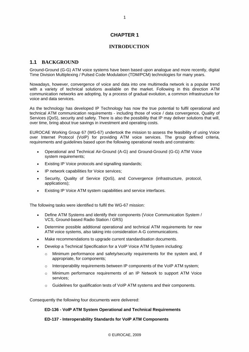
The contents of all four documents are premised on the “Vienna Agreement” which defines the different components of a VoIP ATM system and their mutual interfaces as depicted in Figure 1.
Figure 1: Vienna Agreement VoIP components are interconnected through an IP network and suppliers are free to define their internal architecture (IP/Ethernet, TDM/PCM - Time Division Multiplexing/Pulsed Code Modulation,…). Between VoIP components, required interfaces are defined to guarantee their functional and technical interoperability. Therefore, VoIP ATM Systems are composed of:
• VoIP VCS Components performing Radio and / or Telephone functions, including: 1. Controller Working Positions, assuring HMI including voice devices (microphone and
loudspeaker); 2. Possible local VCS Maintenance and Configuration stations; 3. Possible local Recording devices; 4. Possible LAN for local interconnection; 5. Possible Media Gateways to legacy systems (ATS-QSIG, ATS-R2, ATS-No.5, PSTN,
Radio analogue lines, …). • VoIP Ground Radio Station Components performing AM VHF and UHF Radio functions. • VoIP Supervision System Components performing monitoring and control functions.
© EUROCAE, 2009
3
• VoIP Recording Components performing recording functions. • IP WAN Components performing interconnection services between two or more different
physical components.
1.2 ED-137 PRESENTATION The scope of the WG67 ED-137 Document is to define the rules for VoIP implementations to support ATM communications. This includes the performances requested for radio (Part 1 of ED-137) and the existing signalling in use for telephone (Part 2 of ED-137). The present document, that is the Part 1 of the ED-137, proposes a profile standard for the use of SIP to establish, terminate and modify speech media sessions of the Ground Radio communication service in an Air Traffic Services Ground Voice Network (AGVN). Current Ground-to-Ground (G-G) Air Traffic Management (ATM) voice communication systems (VCS) are based on a hybrid analogue or digital technology, using point-to-point circuits, radios and disparate service infrastructures. ETHERNET and VoIP bring a revolutionary change to provide reliable, cost-effective, and scalable communications capacity to meet future ATM demands. A promising approach exists that will enable an upgrade of the aviation voice network infrastructure using Voice over Internet Protocol (VoIP) technology. The IP technology improvement is capable of supporting a broad variety of ATM applications (Radar data information, Voice communication for Radio and Telephone. This approach yields significant cost savings, enables centralized management, and provides dynamic scalability and reconfiguration of service deployments to meet the changing demands of modern ATM services. SIP is an application layer protocol for establishing, terminating and modifying multimedia sessions. It is typically carried over the Internet Protocol (IP) (RFC 791 [3] and RFC 2460 [6]). Telephone calls are considered as a type of multimedia session where just audio is exchanged. SIP is defined in RFC 3261 [12]. This document proposes a specification for the signalling profile both for basic services, which provide a bi-directional transfer capability for speech media between user terminals in an IP AGVN employing SIP, and for call-related signalling in support of ATS supplementary services.
1.3 TERMINOLOGY FOR REQUIREMENTS, RECOMMENDATIONS AND OPTIONS
The terminology for requirements, recommendations and options in this document is based on RFC 2119 [6], which specifies Best Current Practice regarding the use of Key Words for the Internet Community. As such, the following terminology is applied:
• The word SHALL denotes a mandatory requirement; • The word SHOULD denotes a recommendation; • The word MAY denotes an option.
To avoid confusion with their natural meanings in the English language, the words SHALL, SHOULD, and MAY take on the meaning stated above only where printed in boldface. When printed in normal (Arial) typeface, the natural English meaning is meant.
© EUROCAE, 2009
4
Detailed description of terminology:
1. SHALL: This word has the same meaning as the phrase "REQUIRED" and means that the definition is an absolute requirement of the specification.
2. SHALL NOT: This phrase means that the definition is an absolute prohibition of the
specification.
3. SHOULD: This word, or the adjective "RECOMMENDED", means that there may exist valid reasons in particular circumstances to ignore a particular item, but the full implications must be understood and carefully weighed before choosing a different course.
4. SHOULD NOT: This phrase, or the phrase "NOT RECOMMENDED" mean that there may
exist valid reasons in particular circumstances when the particular behaviour is acceptable or even useful, but the full implications should be understood and the case carefully weighed before implementing any behaviour described with this label.
5. MAY: This word, or the adjective "OPTIONAL", mean that an item is truly optional.
© EUROCAE, 2009
5
CHAPTER 2
RADIO COMMUNICATION MODEL
2.1 DEFINITIONS The following terms are used in this document:
• A/C Call Indication: A/C Call is a term used at the Controller Working Position (CWP) meaning that a transmission is being received on a particular frequency. This event is usually indicated by means of a lamp or other display device.
• A/C TxRx: Aircraft combined Transmitter/Receiver “Transceiver” • Aircraft Call Indication Delay (ACD): The end-to-end delay between a transmission being
received at the ground radio station antenna and the A/C call indication at the Controller Working Position (CWP)
• ARx: A timing parameter associated with a signal received by an aircraft
• ATx: A timing parameter associated with a signal transmitted from an aircraft • Best Signal Selection Input Delay Differential (BIDD): the comparative time difference
between two received signals as inputs to a VCS BSS Device.
• BIDD Max: The maximum value of BIDD as specified by the VCS supplier
• BIDD Variation/Jitter: The range by which BIDD MAY vary over time.
• Best Signal Selection (BSS) Delay: The time taken for BSS to be completed.
• Best Signal Selection (BSS): A process by which a particular radio audio signal is selected “as best” for presentation to the User - and retransmission if cross-coupling is selected.
• Call Established: A call established condition exists when a one-way voice channel (i.e. in half-duplex radio operation) is fully available for use between two Users.
• Call Establishment Delay (CED): The total time taken between the Push-To-Talk (PTT)
action by a User and the time for the squelch to operate in the called party’s receiver. After this time a Call Established condition exists. This is assumed to be equivalent to the FAA term “Voice Channel Set-up delay” below
• Called Party: The User who receives the transmission from the Calling Party.
• Calling Party: The User who initiates a transmission by means of their Push-To-Talk (PTT)
key.
• Controller Working Position (CWP): Contains all the HMI components (i.e. radio, telephone and radar facilities etc) as MAY be required by an individual User in carrying out their operational duties (See also “Sector Suite”).
• Endpoint: is a logical instance responsible with transmission and/or reception of a media
stream
• ECMA: An international industry association dedicated to the standardisation of information and communication systems.
© EUROCAE, 2009
6
• GRx: A timing parameter associated with a signal received on the ground.
• GTx: A timing parameter associated with a signal to be transmitted from the ground.
• PTT- A/C Call Round-Trip Delay: The total time taken between a User operating their Push-To-Talk (PTT) key and when an A/C Call indication appears on their CWP.
• Push-To-Talk Delay (PTTD): This is the delay arising from the need to operate a transmitter
remotely and would be nil if the User was actually physically located in the same place as the transmitter.
• PTT Key: Push to Talk Key – a physical device for carrying out a Push-To-Talk (PTT) action.
• Push To Talk (PTT): The physical action taken by the User in operating their transmit key.
The term “Key” is used to denote any type of device including buttons, levers, foot switches, computer mouse and LCD/Plasma panel segments etc.
• Radio Control Equipment (RCE): used to control radio transmitters and receivers remotely
on the ground.
• Radio Control Equipment – Local (RCE-L): RCE in the locality of the controller.
• Radio Control Equipment - Remote (RCE-R): RCE remote from the controller (i.e. located at the radio station).
• Receiver Activation Time (RAT): The total time taken for a receiver to have detected the
presence of a radio signal of desired minimum quality, causing both the Automatic Gain Control (AGC) proceeded by the squelch mechanism to operate. After this time period the audio channel is fully available within the receiver to present any de-modulated audio at the receiver audio output.
• Receiver De-activation Time (RDAT): The total time taken for a receiver to have detected
the absence of a radio signal that had previously caused Receiver Activation resulting in inhibition of the Automatic Gain Control (AGC) and de-activation of the squelch mechanism. After this time period the audio channel is silent with no audio at the receiver audio output.
• Receiver Recovery After Transmission (RRAT): Receiver Recovery after Transmission
A timing parameter characterising the airborne transceiver operation and specifying the time taken for the receiver audio level after transmission to return to and remain within 3 dB of the steady output obtained with an input signal of 10 microvolts (-93 dBm), modulated 30% at 1000 Hz. (Reference: ED-23B – Minimum Operational Performance Specification for Airborne VHF Receiver – Transmitter operating in the Frequency Range 117.975 – 136.975 MHz (March 1995)).
. • Sector Suite: A number of Controller Working Positions (CWPs) that are co-located so that a
number (typically two or three) Users perform the function of managing a defined area or sector of airspace. As an example a typical Sector Suite MAY be manned by a Controller, Planner and an Assistant each with their own CWP.
• SIP: SIP is the session initiation protocol defined by RFC 3261 [12]. It defines the control
messages to create and terminate communications sessions between multiple endpoints on IP networks.
• SIP Headers: SIP Headers are a set of parameters that could be assigned specific values
inside a SIP message. They convey information about the SIP request or response.
• SIP Messages: SIP Messages are the basic language elements in SIP. Each SIP message contains SIP headers and may contain a message body. There are two types of SIP Messages: Request and Response.
© EUROCAE, 2009
7
• SIP Network Entity: A SIP Network Entity is any network component that supports SIP
signalling.
• SIP Profiles: Profiles in SIP define headers to be used as well and values restrictions and definitions. It also defines which SIP Internet Draft to use and how to use them. Profiles may be defined by any organization. This document defines one of such profiles.
• SIP Request Methods: SIP Request Methods are messages, typically, sent by the SIP client
to initiate a transaction. For example, an INVITE method starts a new call. A CANCEL method cancels the request.
• SIP Responses: SIP Responses are messages received by the SIP client during a
transaction that was initiated by a request. One or more responses can take place in answer to a single request.
• Squelch Delay (SqD): The delay arising from the need to operate the squelch output device
at a location remote from the receiver (usually a Controller Working Position – if installed) and would be nil if the User was actually physically located in the same place as the receiver.
• System: implies entire VCS, Controller Working Positions, IP WAN and all related internal and external interfaces.
• Transmitter Activation Delay Differential (TADD): the comparative difference in time taken
for two transmitters to be activated when keyed from a common point. • Transmitter Activation Delay Differential (TADD) Max: The maximum value of TADD to
ensure satisfactory Multi-carrier/Climax operation. • Transmitter Activation Delay Differential (TADD) Variation / Jitter: The range by which
TADD MAY vary over time. • Transmitter Activation Delay (TAD): the total time taken between the Push-To-Talk (PTT)
action by the User and the time that the transmitter has attained the power level as detailed in the Transmitter Activation Time (TAT) definition.
• Transmitter Activation Time (TAT): the total time taken for a transmitter to have attained a
nominal usable RF power output using a local Push-To-Talk (PTT). After this time the radio frequency is regarded as being in use.
• Transmitter De-activation Time (TDAT): The total time taken for a transmitter power output
to have decayed to a nominal RF power output after removal of a local Push-To-Talk (PTT). After this time the radio frequency is regarded as being free for further use.
• User: an Air Traffic Controller or other operational person carrying out the duties of Air Traffic
Management.
• User Agent Client: A User Agent Client (UAC) is the logical entity within each network component that creates new requests.
• User Agent Server: A User Agent Server (UAS) is the logical entity within each network
component that generates a response to a SIP request. • Voice Communication System (VCS) or Voice Communication Control System (VCCS):
the main equipment providing radio (and telephone) facilities to the Controller Working Position.
• VAD: Voice Activity Detection
© EUROCAE, 2009
8
• Voice Delay: the one-way User-to-User voice delay between analogue system interfaces (Example: Controller microphone to Pilot Earphone) once the call is established.
• XC1 (Frequency coupling time): a timing parameter specifying the time taken for a VCS (or
other device) to couple one frequency to another. In practical terms this is the time taken for an A/C Call (Squelch) signal as an input to the VCS to be converted to a Push-To-Talk (PTT) signal as an output from the VCS.
• XC2 (Cross-coupled Push-To-Talk Inhibition Period): a timing parameter specifying a
period imposed by a VCS (or other device) during which retransmission is inhibited after any transmission (within the cross-coupled group) via the VCS has ended. This inhibition is a technical solution necessary to prevent either cross-coupling oscillation and/or blocking behaviour in cross-coupled mode.
• X-Couple (Cross-Coupling 2 or more radio frequencies): frequency cross-coupling is a
CWP selected function causing automatic retransmission of one received signal on other pre-selected radio frequencies. With Cross-Coupling it is possible to merge a number of physical radio frequencies into a kind of logical frequency.
2.2 PROTOCOL STACK
1 [COMMUNICATION MODEL] Aim of the specifications
The specifications provided hereafter SHALL concern the interface between the VCS and the Radio remote sites for the following subjects:
• Audio • Signalling • Management
2 [COMMUNICATION MODEL] Applicable configurations
The specification SHALL provide the definition of the interface between VCS and Radios in the following configurations:
• VCS to radios with Tx and Rx located at the same site; • VCS to radios with Tx and Rx located at different sites.
2.3 BASIC PROTOCOL REQUIREMENTS To establish a communication between a VCS site and a Radio equipment, the basic protocol requirements for the equipment to provide the functionality are the following
• SIP protocol used to initiate the link between the VCS and the radio equipment. • RTP protocol allowing the transport of audio packets and radio signalling using header
extension included in RTP protocol;
3 [COMMUNICATION MODEL] Applicable Protocol
SIP Protocol and RTP protocol SHALL be the minimum implementation to provide VoIP communication between VCS and Radio
© EUROCAE, 2009
9
4 [COMMUNICATION MODEL] Simultaneous communications between VCS and Radios
A radio may be shared by several VCS sites. To comply with this requirement,
a radio SHALL be able to establish 7 SIP sessions and process 7 RTP connections
2.4 MODES OF OPERATION 2.4.1 Real time Transport Protocol (RTP) and Real time Transport Header Extension
The Real time Transport Protocol will be used to transport voice packets in real time. The Real time Transport Protocol Header Extension will be employed to transport the following signalling information in real time:
a) PTT (Push To Talk) b) Aircraft Call (A/C call), also nominated Squelch (SQL); c) Quality index (used for the Best Signal Signalling feature) d) Time stamping information (used for CLIMAX application) e) Reserved field for proprietary applications f) Keep alive message
When no voice has to be exchanged, the Real time Transport Protocol does not need to transport voice packets. Smaller RTP packet including Header extension will be employed for signalling exchange only.
2.4.2 Connection init using SIP signalling protocol
5 [COMMUNICATION MODEL] Communication initiation between VCS and Radios
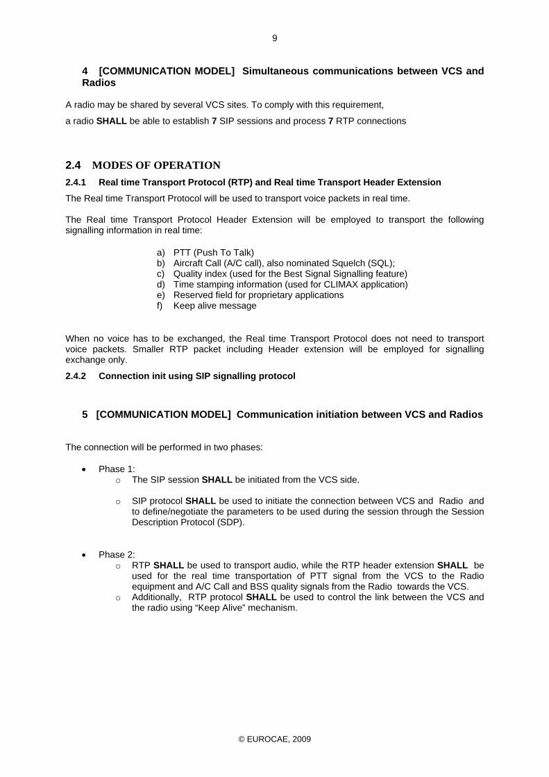
The connection will be performed in two phases:
• Phase 1: o The SIP session SHALL be initiated from the VCS side. o SIP protocol SHALL be used to initiate the connection between VCS and Radio and
to define/negotiate the parameters to be used during the session through the Session Description Protocol (SDP).
• Phase 2:
o RTP SHALL be used to transport audio, while the RTP header extension SHALL be used for the real time transportation of PTT signal from the VCS to the Radio equipment and A/C Call and BSS quality signals from the Radio towards the VCS.
o Additionally, RTP protocol SHALL be used to control the link between the VCS and the radio using “Keep Alive” mechanism.
© EUROCAE, 2009
10
Figure 2: SIP connection between VCS and Single Tx/Rx Radio
2.4.3 SIP connections with separate Tx and RX Radio equipment
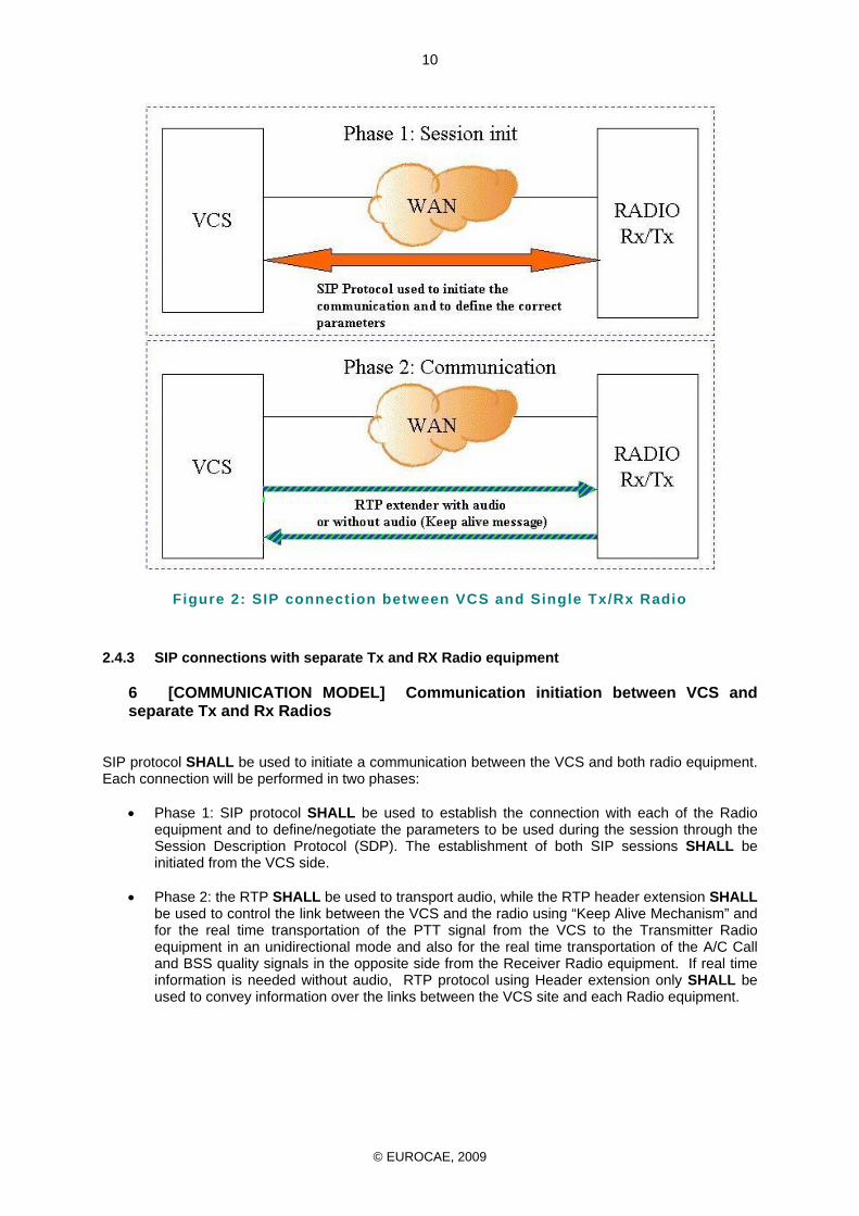
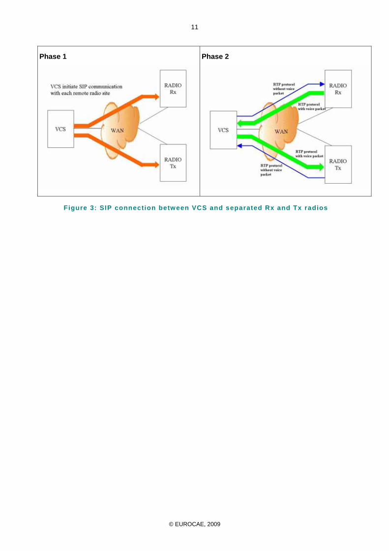
6 [COMMUNICATION MODEL] Communication initiation between VCS and separate Tx and Rx Radios
SIP protocol SHALL be used to initiate a communication between the VCS and both radio equipment. Each connection will be performed in two phases:
• Phase 1: SIP protocol SHALL be used to establish the connection with each of the Radio equipment and to define/negotiate the parameters to be used during the session through the Session Description Protocol (SDP). The establishment of both SIP sessions SHALL be initiated from the VCS side.
• Phase 2: the RTP SHALL be used to transport audio, while the RTP header extension SHALL
be used to control the link between the VCS and the radio using “Keep Alive Mechanism” and for the real time transportation of the PTT signal from the VCS to the Transmitter Radio equipment in an unidirectional mode and also for the real time transportation of the A/C Call and BSS quality signals in the opposite side from the Receiver Radio equipment. If real time information is needed without audio, RTP protocol using Header extension only SHALL be used to convey information over the links between the VCS site and each Radio equipment.
© EUROCAE, 2009
11
Phase 1 Phase 2
Figure 3: SIP connection between VCS and separated Rx and Tx radios
© EUROCAE, 2009
12
2.4.4 SIP connections with different Radio equipment working in CLIMAX mode
7 [COMMUNICATION MODEL] Communication between VCS and Radios in Climax mode
The CLIMAX mode is the capability to operate a frequency using simultaneously several radios located on different sites.
- 2 to 7 Radios SHALL be operated in CLIMAX mode.
The CLIMAX implementation is mainly driven by the need to : - reduce the influence of terrain mask especially for low-level sectors - enable extended range coverage - cope with the unavailability or the lack of suitable location of existing ground stations
The consequences when using several radios on the same frequency is echo due to transmission delay between lines or voice packetization. The echo occurs when two or more identical audio signals are received and demodulated with relative time delays. This phenomenon can appear either on board or on ground where these incoming signals are combined in the audio circuitry of the airborne receiver or of the VCS respectively. The time delay differences in ground-ground transmission need to be compensated for controller to pilot communications. This could be adjusted by introducing fitted delay line or software equivalent delay for voice at VCS and /or Radio equipment Due to the variation of the delay using VoIP technology, information regarding the relative time delay between remote radio equipment and VCS site SHALL be evaluated. Time stamping included in RTP SHALL be used for this purpose. CLIMAX delay parameter is also defined and SHALL be transmitted from the VCS to the Radio equipment. (See Chapter 2.4.1d) The System SHALL provide compensation to keep time delay differences within the 10ms limit. The means of compensation SHALL not result in degradation of voice quality. At the VCS side, compensation SHALL be provided between the different radios receivers, involved in a CLIMAX frequency, to guarantee voice delay not exceeding the 10 ms difference. At the remote sites, information SHALL be provided to transmitters, involved in a CLIMAX frequency, regarding the delay adjustment needed to compensate the voice delay, not exceeding the 10 ms difference, between transmission sites Remark: Clock synchronization using standard IP protocol or external synchronization system needed to update Time Stamp field of the RTP protocol are out of scope of this document.
-
© EUROCAE, 2009
13
CHAPTER 3
SIGNALLING
3.1 INTRODUCTION SIP protocol is used to initiate a connection. SIP SHALL permit the establishment of a connection between two endpoints. SIP is an application-layer control protocol which has been developed and designed within the IETF and is defined by RFC 3261 [12]. The protocol is used for creating, modifying, and terminating sessions with one or more participants. For the Ground Radio application the main purpose of the SIP signalling protocols is to create a communication path between endpoints and once this is achieved, the voice and signalling relevant to the radio communication itself SHALL employ RTP with header extension as described in the next chapter. The audio transport SHALL be supported by the Real-time Transport Protocol (RTP) (RFC 3550 [22] and MAY be augmented by its associated control protocol (RTCP) to allow monitoring of voice packet delivery. The benefits of this implementation can be described as follows
• Support for legal voice recording at any point between the session endpoints.
• Support for Firewall traversal by RTP streams.
• Support for traversal of NAT points by RTP packets.
• A stronger control over the session’s establishment, life and termination due to the simplicity and thus predictability of all aspects.
3.2 SESSION INITIATION PROTOCOL The objective of SIP is to establish, terminate and modify speech media sessions of the Ground Radio Service in an Air Traffic Services Ground Voice Network (AGVN).
3.2.1.1 Signalling Signalling in an IP AGVN SHALL be based on the Session Initiation Protocol (SIP) [12]. SIP is an application-layer transaction protocol that provides advanced signalling and control functionality for a large range of multimedia communications.
3.2.2 PROFILE STANDARD FOR THE USE OF SIP IN AN AGVN
1 [SIP] SIP Version
An Air Traffic Services VoIP Communications System SHALL support SIP version 2 as specified in RFC 3261 [12].
3.2.2.1 LOGICAL ATS-SIP ENTITIES The logical ATS SIP Entities like, User Agent, Registrar and Proxy Server are described in the EUROCAE ED-137 Part 2 – Telephone document [38]. For the Ground Radio Service of the IP AGVN the SIP Entities Registrar and Proxy Server are optional. Therefore also all services of the User Agent
© EUROCAE, 2009
14
regarding Registration are optional.
3.2.3 SUPPORTED REQUESTS
2 [SIP] SIP Supported requests
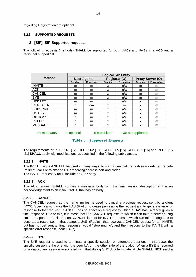
The following requests (methods) SHALL be supported for both UACs and UASs in a VCS and a radio that support SIP:
Logical SIP Entity User Agents Registrar (O) Proxy Server (O) Method
Sending Receiving Sending Receiving Sending Forwarding INVITE m m x n/a m m ACK m m x n/a m m CANCEL m m x n/a m m BYE m m x n/a m m UPDATE m m x n/a x m REGISTER o n/a x m x m SUBSCRIBE m m x n/a x m NOTIFY m m x n/a x m OPTIONS o m x n/a x m REFER o m x n/a x m MESSAGE o m x n/a x m
m: mandatory; o: optional; x: prohibited; n/a: not applicable
Table 1 – Supported Requests
The requirements of RFC 3261 [12], RFC 3262 [13] , RFC 3265 [15], RFC 3311 [16] and RFC 3515 [21] SHALL apply with modifications as specified in the following sub-clauses.
3.2.3.1 INVITE The INVITE request SHALL be used in many ways: to start a new call, refresh session-timer, reroute (redirect) calls or to change RTP receiving address port and codec. The INVITE request SHALL include an SDP body.
3.2.3.2 ACK The ACK request SHALL contain a message body with the final session description if it is an acknowledgement to an initial INVITE that has no body.
3.2.3.3 CANCEL The CANCEL request, as the name implies, is used to cancel a previous request sent by a client (VCS). Specifically, it asks the UAS (Radio) to cease processing the request and to generate an error response to that request. CANCEL has no effect on a request to which a UAS has already given a final response. Due to this, it is most useful to CANCEL requests to which it can take a server a long time to respond. For this reason, CANCEL is best for INVITE requests, which can take a long time to generate a response. In that usage, a UAS (Radio) that receives a CANCEL request for an INVITE, but has not yet sent a final response, would "stop ringing", and then respond to the INVITE with a specific error response (code: 487).
3.2.3.4 BYE The BYE request is used to terminate a specific session or attempted session. In this case, the specific session is the one with the peer UA on the other side of the dialog. When a BYE is received on a dialog, any session associated with that dialog SHOULD terminate. A UA SHALL NOT send a
© EUROCAE, 2009
15
BYE outside of a dialog.
3.2.3.5 REGISTER Registration entails sending a REGISTER request to a special type of UAS known as a REGISTRAR. A registrar acts as the front end to the location service for a domain, reading and writing mappings based on the contents of REGISTER requests. This location service is then typically consulted by a proxy server that is responsible for routing requests for that domain. If a registration between a SIP UA and a SIP server (SIP proxy, SIP registrar) is accomplished, the (authentication) process SHALL be made in accordance with section 10 of RFC 3261 [12], and section 2 of RFC 3265 [15] SUPPORTED RESPONSES.
3.2.3.6 WG67 KEY-IN Event Package This event package SHALL be used to inform a SIP UA about actual bindings between ptt-id and SIP URI from a SIP UA (e.g. VCS) keyed-in at a transmitter. The binding information SHALL be transmitted as a comma separated text string, with each pair separated using carriage return and line feed (crlf) within a NOTIFY message body defined as follows: <ptt-id-1, decimal value>, <sip-from-uri-1, sipuri format>crlf<ptt-id-2, decimal value>, <sip-from-uri-1, sipuri format>crlf <ptt-id-3, decimal value>, <sip-from-uri-2, sipuri format>crlf <ptt-id-n, decimal value>, <sip-from-uri-n, sipuri format>crlf Example: 1,sip:user_a@domain 2,sip:user_b@domain SIP specific event notification mechanisms ([15]) SHALL be used to distribute this data.
3.2.3.6.1 SUBSCRIBE
The SUBSCRIBE method is used to request current state and state updates from a remote node. The Request URI of a SUBSCRIBE request,contains enough information to route the request to the appropriate entity (e.g. radio or radio gateway equipment). It SHALL include exactly one "Event" header indicating the event being subscribed. The "Event" header SHALL contain the token “WG67 KEY-IN” which is indicating the type of state for which a subscription is being requested. If subscription between SIP UAs (e.g. VCS and radio) is accomplished, the process SHALL be made in accordance with RFC 3265 [15]
3.2.3.6.2 NOTIFY
NOTIFY messages are sent to inform subscribers of changes in state to which the subscriber has a subscription. As in SUBSCRIBE requests, the NOTIFY "Event" header SHALL contain “WG67 KEY-IN” as single event package name for which a notification is being generated. The “Content-type” header SHALL contain: text/plain. The radio or radio gateway equipment SHALL notify all subscribers whenever a new participant keys-in or keys-out this frequency with the complete list of bindings between ptt-id and SIP URIs, meaning that key-in or key-out are events that trigger a notification, containing the list of all current bindings. A SIP UA (e.g. VCS) SHOULD use this binding information to identify an entity currently transmitting on that radio (identified by the “From” header in the notification) by its SIP URI. The ptt-id identifying the current speaker will be received via the PTT header extension, see 5.10.2 RTP Header extension. If subscription between SIP UAs (e.g. VCS and radio) is accomplished, the process SHALL be made in accordance with RFC 3265 [15]
© EUROCAE, 2009
16
3.2.4 SUPPORTED RESPONSES
The following sections specify the default requirements for a VCS or a Radio that supports SIP.
3 [SIP] SIP Supported response
The requirements of RFC 3261 [12] and RFC 3265 [15] SHALL apply with modifications as specified in the following sub-clauses.
3.2.4.1 1xx Provisional Responses Support for the following SIP responses SHALL be required for all UAs: • 100 Trying • 180 Ringing • 181 Call Is Being Forwarded • 182 Queued • 183 Session Progress
3.2.4.1.1 100 Trying The SDP body SHALL NOT be used in the 100 Trying response; if such a message contains this field, it SHALL be ignored.
3.2.4.1.2 180 Ringing This response SHOULD not be used on the radio. When receiving an INVITE, the radio SHALL provide Trying. The SDP body SHALL NOT be used in the 180 Ringing response; if such a message contains this field, it SHALL be ignored. Early Media functionality is only done via the 183 Session Progress response.
3.2.4.1.3 183 Session Progress The 183 response SHALL be sent when audio has to be sent. This response MAY contain an SDP body, which also includes information of the codec and audio port for early audio session. This response SHALL contain an SDP body if the UAS wants to provide early media.
3.2.4.2 2xx Successful Responses Support for the following SIP responses is REQUIRED for all UAs: • 200 OK • 202 Accepted
3.2.4.2.1 200 OK A 200 OK response SHALL be sent if the request is properly processed. It Should contain an SDP body to exchange the radio’s capabilities. The 200 OK response to a CANCEL, BYE, SUBSCRIBE, NOTIFY, MESSAGE SHALL NOT have an SDP body. If these messages contain this field, it SHALL be ignored.
3.2.4.2.2 202 Accepted The 202 Accepted response SHALL be sent when a SUBSCRIBE request has been accepted for processing, but the processing has not been completed.
© EUROCAE, 2009
17
3.2.4.2.3 3xx Redirection Responses Support for 3xx Redirection Responses is OPTIONAL for all UAs. UACs that do not support 3xx Redirection Responses SHALL treat a 3xx response as a 4xx Request Failure response.
3.2.4.2.4 4xx Request Failure Responses Support for the following 4xx Request Failure responses SHALL be REQUIRED for all UAs: • 400 Bad Request • 401 Unauthorized • 403 Forbidden • 404 Not Found • 405 Method Not Allowed • 406 Not Acceptable • 407 Proxy Authentication Required • 408 Request Timeout • 410 Gone • 413 Request Entities Too Large • 414 Request URI Too Long • 415 Unsupported Media Type • 416 Unsupported URI Scheme • 420 Bad Extension • 421 Extension Required • 423 Interval Too Brief • 480 Temporarily Unavailable • 481 Call Leg/Transaction Does Not Exist • 482 Loop Detected • 483 Too Many Hops • 484 Address Incomplete • 485 Ambiguous • 486 Busy Here • 487 Request Cancelled • 488 Not Acceptable Here • 489 Bad Event • 491 Request Pending • 493 Undecipherable
3.2.4.2.5 5xx Server Error Responses Support for the following 5xx Server Error responses SHALL be REQUIRED for all UAs: • 500 Internal Server Error • 501 Not Implemented • 502 Bad Gateway • 503 Service Unavailable • 504 Server Time-out • 505 Version Not Supported • 513 Message Too Large
3.2.4.2.6 6xx Global Failure Responses Support for the following 6xx Global Failure responses SHALL be REQUIRED for all UAs: • 600 Busy Everywhere • 603 Decline • 604 Does Not Exist Anywhere • 606 Not Acceptable
© EUROCAE, 2009
18
3.2.4.3 SUPPORTED HEADER FIELDS The requirements of RFC 3261 [12], RFC 3265 [15], RFC 3311 [16] and RFC 3515 [23] SHALL apply with modifications as specified in the following sub-clauses.
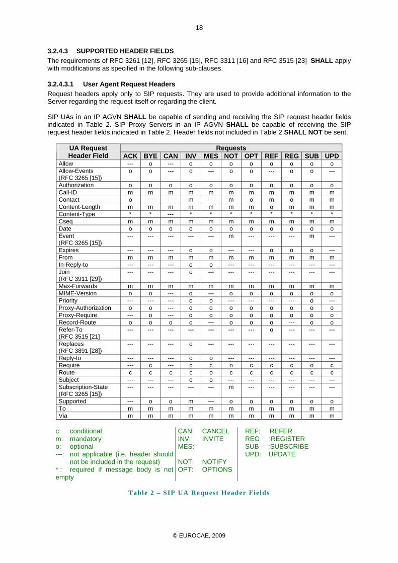
3.2.4.3.1 User Agent Request Headers Request headers apply only to SIP requests. They are used to provide additional information to the Server regarding the request itself or regarding the client. SIP UAs in an IP AGVN SHALL be capable of sending and receiving the SIP request header fields indicated in Table 2. SIP Proxy Servers in an IP AGVN SHALL be capable of receiving the SIP request header fields indicated in Table 2. Header fields not included in Table 2 SHALL NOT be sent.
Requests UA Request Header Field ACK BYE CAN INV MES NOT OPT REF REG SUB UPD
Allow --- o --- o o o o o o o o Allow-Events (RFC 3265 [15])
o o --- o --- o o --- o o ---
Authorization o o o o o o o o o o o Call-ID m m m m m m m m m m m Contact o --- --- m --- m o m o m m Content-Length m m m m m m m o m m m Content-Type * * --- * * * * * * * * Cseq m m m m m m m m m m m Date o o o o o o o o o o o Event (RFC 3265 [15])
--- --- --- --- --- m --- --- --- m ---
Expires --- --- --- o o --- --- o o o --- From m m m m m m m m m m m In-Reply-to --- --- --- o o --- --- --- --- --- --- Join (RFC 3911 [29])
--- --- --- o --- --- --- --- --- --- ---
Max-Forwards m m m m m m m m m m m MIME-Version o o --- o --- o o o o o o Priority --- --- --- o o --- --- --- --- o --- Proxy-Authorization o o --- o o o o o o o o Proxy-Require --- o --- o o o o o o o o Record-Route o o o o --- o o o --- o o Refer-To (RFC 3515 [21]
--- --- --- --- --- --- --- o --- --- ---
Replaces (RFC 3891 [28])
--- --- --- o --- --- --- --- --- --- ---
Reply-to --- --- --- o o --- --- --- --- --- --- Require --- c --- c c o c c c o c Route c c c c o c c c c c c Subject --- --- --- o o --- --- --- --- --- --- Subscription-State (RFC 3265 [15])
--- --- --- --- --- m --- --- --- --- ---
Supported --- o o m --- o o o o o o To m m m m m m m m m m m Via m m m m m m m m m m m
c: conditional m: mandatory o: optional ---: not applicable (i.e. header should
not be included in the request) * : required if message body is not empty
CAN: CANCEL INV: INVITE MES:
NOT: NOTIFY OPT: OPTIONS
REF: REFER REG :REGISTER SUB :SUBSCRIBE UPD: UPDATE
Table 2 – SIP UA Request Header Fields
© EUROCAE, 2009
19
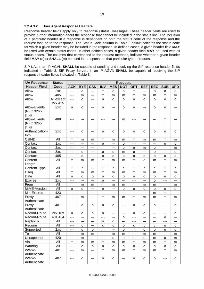
3.2.4.3.2 User Agent Response Headers Response header fields apply only to response (status) messages. These header fields are used to provide further information about the response that cannot be included in the status line. The inclusion of a particular header in a response is dependent on both the status code of the response and the request that led to the response. The Status Code column in Table 3 below indicates the status code for which a given header may be included in the response. In defined cases, a given header field MAY be used with certain status codes. In other defined cases, a given header field MAY be used with all status codes. The columns that correspond to the request methods, indicate whether a given header field MAY (o) or SHALL (m) be used in a response to that particular type of request. SIP UAs in an IP AGVN SHALL be capable of sending and receiving the SIP response header fields indicated in Table 3. SIP Proxy Servers in an IP AGVN SHALL be capable of receiving the SIP response header fields indicated in Table 3.
Requests UA Response Header Field
Status Code ACK BYE CAN INV MES NOT OPT REF REG SUB UPD
Allow 2xx --- o --- m o o m --- o o o Allow 405 --- m --- m m m m m m m m Allow All except
2xx,415 --- o --- o o o o o o o o
Allow-Events (RFC 3265 [15])
2xx o o --- o --- o o --- o o ---
Allow-Events (RFC 3265 [15])
489 --- --- --- --- --- m --- --- --- m ---
Authentication-Info
2xx --- o --- o o o o o o o o
Call-ID All m m m m m m m m m m m Contact 1xx --- --- --- o --- o --- --- --- o o Contact 2xx --- --- --- m --- o o m o m m Contact 3xx --- o --- o o m o --- o m o Contact 485 --- o --- o o o o o o o o Content-Length
All m m m m m m m o m m m
Content-Type All * * --- * * * * * * * * Cseq All m m m m m m m m m m m Date All o o o o o o o o o o o Expires 2xx --- --- --- o --- --- --- --- o --- --- From All m m m m m m m m m m m MIME-Version All o o --- o --- o o o o o o Min-Expires 423 --- --- --- --- --- --- --- --- m m --- Proxy-Authenticate
407 --- m --- m m m m m m m m
Proxy-Authenticate
401 --- o o o o --- o o o --- o
Record-Route 2xx,18x o o o o --- --- o o --- --- o Record-Route 401,484 --- --- --- --- --- o --- --- --- o --- Reply-To All --- --- --- o o --- --- --- --- --- --- Require All --- c --- c c o c c c o c Supported 2xx --- o o m --- o m o o o o To All m m m m m m m m m m m Unsupported 420 --- m --- m o o m o m o m Via All m m m m m m m m m m m Warning All --- o o o o o o o o o o WWW-Authenticate
401 --- m --- m m m m m m m m
WWW-Authenticate
407 --- o --- o o --- o o o --- o
© EUROCAE, 2009
20
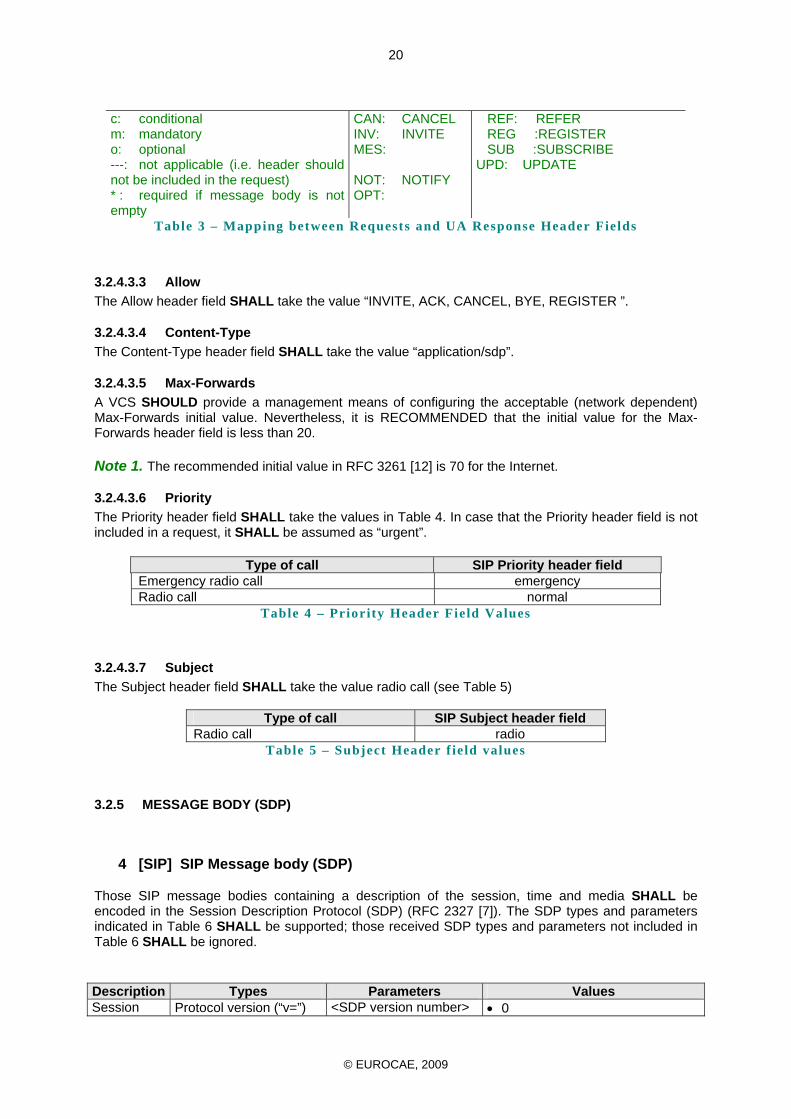
c: conditional m: mandatory o: optional ---: not applicable (i.e. header should not be included in the request) * : required if message body is not empty
CAN: CANCEL INV: INVITE MES:
NOT: NOTIFY OPT:
REF: REFER REG :REGISTER SUB :SUBSCRIBE
UPD: UPDATE
Table 3 – Mapping between Requests and UA Response Header Fields
3.2.4.3.3 Allow The Allow header field SHALL take the value “INVITE, ACK, CANCEL, BYE, REGISTER ”.
3.2.4.3.4 Content-Type The Content-Type header field SHALL take the value “application/sdp”.
3.2.4.3.5 Max-Forwards A VCS SHOULD provide a management means of configuring the acceptable (network dependent) Max-Forwards initial value. Nevertheless, it is RECOMMENDED that the initial value for the Max-Forwards header field is less than 20. Note 1. The recommended initial value in RFC 3261 [12] is 70 for the Internet.
3.2.4.3.6 Priority The Priority header field SHALL take the values in Table 4. In case that the Priority header field is not included in a request, it SHALL be assumed as “urgent”.
Type of call SIP Priority header field Emergency radio call emergency Radio call normal
Table 4 – Priority Header Field Values
3.2.4.3.7 Subject The Subject header field SHALL take the value radio call (see Table 5)
Type of call SIP Subject header field Radio call radio
Table 5 – Subject Header f ie ld values
3.2.5 MESSAGE BODY (SDP)
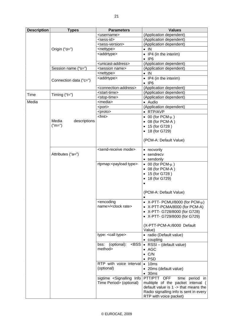
4 [SIP] SIP Message body (SDP)
Those SIP message bodies containing a description of the session, time and media SHALL be encoded in the Session Description Protocol (SDP) (RFC 2327 [7]). The SDP types and parameters indicated in Table 6 SHALL be supported; those received SDP types and parameters not included in Table 6 SHALL be ignored. Description Types Parameters Values Session Protocol version (“v=”) <SDP version number> • 0
© EUROCAE, 2009
21
Description Types Parameters Values <username> (Application dependent) <sess-id> (Application dependent) <sess-version> (Application dependent) <nettype> • IN <addrtype> • IP4 (in the interim)
• IP6
Origin (“o=”)
<unicast-address> (Application dependent) Session name (“s=”) <session name> (Application dependent)
<nettype> • IN <addrtype> • IP4 (in the interim)
• IP6 Connection data (“c=”)
<connection-address> (Application dependent) <start-time> (Application dependent) Time Timing (“t=”) <stop-time> (Application dependent) <media> • Audio <port> (Application dependent) <proto> • RTP/AVP
Media descriptions (“m=”)
<fmt> • 00 (for PCM-μ ) • 08 (for PCM-A ) • 15 (for G728 ) • 18 (for G729) (PCM-A: Default Value)
<send-receive mode> • recvonly • sendrecv • sendonly
rtpmap:<payload type> • 00 (for PCM-μ ) • 08 (for PCM-A ) • 15 (for G728 ) • 18 (for G729) • (PCM-A: Default Value) •
<encoding name>/<clock rate>
• X-PTT- PCMU/8000 (for PCM-μ) • X-PTT-PCMA/8000 (for PCM-A) • X-PTT- G728/8000 (for G728) • X-PTT- G729/8000 (for G729) (X-PTT-PCM-A:/8000 Default Value)
type: <call type> • radio (Default value) • coupling
bss: (optional): <BSS method>
• RSSI – (default value) • AGC • C/N • PSD
RTP with voice interval (optional)
• 10ms • 20ms (default value) • 30ms
Media
Attributes (“a=”)
sigtime <Signalling Info Time Period> (optional)
PTT/PTT OFF time period in mulitiple of the packet interval ( default value is 1 -> that means the Radio signalling info is sent in every RTP with voice packet)
© EUROCAE, 2009
22
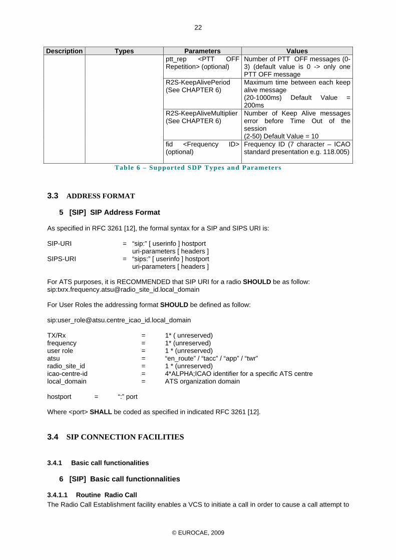
Description Types Parameters Values ptt_rep <PTT OFF Repetition> (optional)
Number of PTT OFF messages (0-3) (default value is 0 -> only one PTT OFF message
R2S-KeepAlivePeriod (See CHAPTER 6)
Maximum time between each keep alive message (20-1000ms) Default Value = 200ms
R2S-KeepAliveMultiplier (See CHAPTER 6)
Number of Keep Alive messages error before Time Out of the session (2-50) Default Value = 10
fid <Frequency ID> (optional)
Frequency ID (7 character – ICAO standard presentation e.g. 118.005)
Table 6 – Supported SDP Types and Parameters
3.3 ADDRESS FORMAT
5 [SIP] SIP Address Format
As specified in RFC 3261 [12], the formal syntax for a SIP and SIPS URI is: SIP-URI = “sip:” [ userinfo ] hostport uri-parameters [ headers ] SIPS-URI = “sips:” [ userinfo ] hostport uri-parameters [ headers ] For ATS purposes, it is RECOMMENDED that SIP URI for a radio SHOULD be as follow: sip:txrx.frequency.atsu@radio_site_id.local_domain For User Roles the addressing format SHOULD be defined as follow: sip:[email protected]_icao_id.local_domain TX/Rx = 1* ( unreserved) frequency = 1* (unreserved) user role = 1 * (unreserved) atsu = “en_route” / “tacc” / “app” / “twr” radio_site_id = 1 * (unreserved) icao-centre-id = 4*ALPHA;ICAO identifier for a specific ATS centre local_domain = ATS organization domain hostport = “:” port Where <port> SHALL be coded as specified in indicated RFC 3261 [12].
3.4 SIP CONNECTION FACILITIES
3.4.1 Basic call functionalities
6 [SIP] Basic call functionnalities
3.4.1.1 Routine Radio Call The Radio Call Establishment facility enables a VCS to initiate a call in order to cause a call attempt to
© EUROCAE, 2009
23
be made to the Radio supplied address, this is equivalent to normal dialled telephone operation. The establishment and clearing of a Radio call SHALL be handled as specified in RFC 3261 [12] and RFC 3665 [24].
3.4.1.2 Call Priority The Priority facility is a means to force access to a radio for high priority or emergency calls. If the INVITE includes the Priority header field with value “emergency” and the radio doesn’t allow an additional radio call, the device SHALL interrupt a call with a lower priority and accept this high priority call.
3.4.1.3 Interaction with Other ATS Supplementary Services
3.4.1.3.1 Call Priority Interruption A priority radio call SHALL NOT be interrupted.
3.4.1.3.2 Call Intrusion Call Intrusion SHALL NOT be allowed.
3.4.1.3.3 Call Pickup The Call Pickup service enables a user to answer a call that is in the alerting phase (ringing) at another user's terminal. Call Pickup SHALL NOT be allowed.
3.4.1.3.4 Call Hold The Hold service allows a user to disconnect temporarily from an established call in order to carry out other telephony functions before returning to the original established call. Call Hold SHALL NOT be allowed.
3.4.1.3.5 Call Transfer The Call Transfer service enables a user involved in an active call to establish a new call between the other user in the active call and a third party. Call Transfer SHALL NOT be allowed.
3.4.1.3.6 Conference The Conference service enables a user to interconnect a number of parties. Call conference SHALL NOT be allowed.
3.4.1.3.7 Call Diversion The Call Diversion service enables a user to cause all incoming DA and IDA calls to that user to be routed to another user in the following circumstances: Call Diversion SHALL NOT be allowed.
3.4.1.3.8 Position Monitor The Position Monitor service enables a user to hear any active voice call at other user terminal (position); the served user hears audio transmitted and received by the monitored position. Position monitor SHALL NOT be allowed.
© EUROCAE, 2009
24
3.4.2 AUDIBLE TONES
7 [SIP] SIP Audible Tones control
Normally, All SIP User Agents must be capable of providing users with audible tones, in order to indicate call progress following the receipt of signalling messages in different call states. As Radio equipment will be connect automatically, audible tone SHALL NOT be provided
3.4.3 Call Set Up Procedure
8 [SIP] SIP Call Set Up procedure
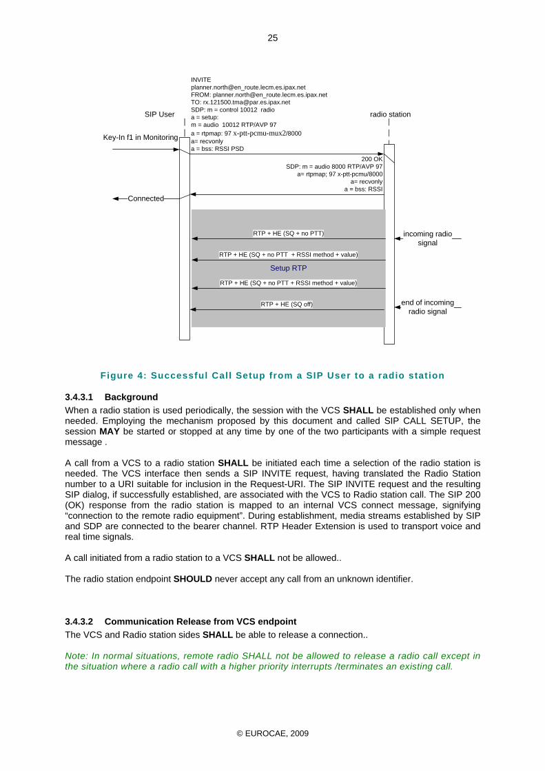
The following sequence is a simple example of a call set-up procedure :
1. To initiate a session, the caller (or User Agent Client) sends a request with the SIP URL of the called party. In the Radio application, the caller will be the VCS side and the called party the remote radio side.
2. If the client knows the location of the other party it can send the request directly to their IP address; if not, the client can send it to a locally configured SIP network server.
3. The server will attempt to resolve the called user's location and send the request to them. There are many ways it can do this, such as searching the DNS or accessing databases. Alternatively, the server may be a redirect server that may return the called user location to the calling client for it to try directly. During the course of locating a user, one SIP network server can proxy or redirect the call to additional servers until it arrives at one that definitely knows the IP address where the called user can be found.
4. Once found, the request is sent to the user and then several options arise. In the simplest case, the user's remote radio client receives the request, that is, the user's remote radio client responds to the invitation with the designated capabilities* of the client software and a connection is established.
* "Designated capabilities" refers to the functions that the user wants to invoke. The client software might support voice compression, for example, but the user may only want to use the ITU-T G.711 voice codec [35].
Below is a typical message sequence for a successful Radio call setup between the SIP user agent’s on the VCS side and Radio Station Side. The SIP call is made from a controller at the VCS side over the IP network to a nominated Frequency at the Radio Station Side.
© EUROCAE, 2009
25
Key-In f1 in Monitoring
SIP User
INVITE planner.north@en_route.lecm.es.ipax.netFROM: planner.north@en_route.lecm.es.ipax.netTO: [email protected]: m = control 10012 radioa = setup:m = audio 10012 RTP/AVP 97a = rtpmap: 97 x-ptt-pcmu-mux2/8000a= recvonlya = bss: RSSI PSD
200 OKSDP: m = audio 8000 RTP/AVP 97
a= rtpmap; 97 x-ptt-pcmu/8000a= recvonly
a = bss: RSSI
Setup RTP
incoming radio signal
end of incoming radio signal
Connected
RTP + HE (SQ + no PTT)
RTP + HE (SQ + no PTT + RSSI method + value)
RTP + HE (SQ + no PTT + RSSI method + value)
RTP + HE (SQ off)
radio station
Figure 4: Successful Call Setup from a SIP User to a radio stat ion
3.4.3.1 Background When a radio station is used periodically, the session with the VCS SHALL be established only when needed. Employing the mechanism proposed by this document and called SIP CALL SETUP, the session MAY be started or stopped at any time by one of the two participants with a simple request message . A call from a VCS to a radio station SHALL be initiated each time a selection of the radio station is needed. The VCS interface then sends a SIP INVITE request, having translated the Radio Station number to a URI suitable for inclusion in the Request-URI. The SIP INVITE request and the resulting SIP dialog, if successfully established, are associated with the VCS to Radio station call. The SIP 200 (OK) response from the radio station is mapped to an internal VCS connect message, signifying “connection to the remote radio equipment”. During establishment, media streams established by SIP and SDP are connected to the bearer channel. RTP Header Extension is used to transport voice and real time signals. A call initiated from a radio station to a VCS SHALL not be allowed.. The radio station endpoint SHOULD never accept any call from an unknown identifier.
3.4.3.2 Communication Release from VCS endpoint The VCS and Radio station sides SHALL be able to release a connection.. Note: In normal situations, remote radio SHALL not be allowed to release a radio call except in the situation where a radio call with a higher priority interrupts /terminates an existing call.
© EUROCAE, 2009
26
CHAPTER 4
AUDIO
4.1 INTRODUCTION The proposed audio transmission over an IP network is based on the Real time Transport Protocol as defined by RFC3550 [22] . Based on this protocol, an extension field is used to insert some real time commands needed by radio applications for the transport of the PTT, SQL and BSS signals..
4.2 AUDIO SPECIFICATION 4.2.1 Audio Level
1 [AUDIO] Audio level specifications
4.2.1.1 Rx path requirement
The radio receiver SHALL produce a –10 dbm0 +/- 1dB audio output level when a 30% AM modulated RF signal is applied at the RF input.
4.2.1.2 TX path requirement The radio transmitter SHALL produce a 30% AM modulated RF output signal, when a –10dBm0 +/- 1dB audio input level is applied in the digital domain.
4.2.2 Audio Quality
4.2.2.1 Qualification of the communication
2 [AUDIO] Voice quality
The voice quality of a radio communication is defined using a voice quality estimation methodology nominated “Mean Opinion Score” (MOS) rating. The MOS scale was formulated as the result of subjective studies. In subjective testing, subjects are requested to classify the perceived voice quality into categories (MOS rates the quality of the voice signal in one of the following categories: excellent (5), good(4), fair(3), poor(2) and bad(1)).
• To minimize the consequence of voice degradation, the MOS value of the Radio Call over the ground segment to and from the Radio equipment SHALL be equal or better than 4;
4.2.2.2 Delay introduced by audio processing and propagation
3 [AUDIO] Voice latency time performance
The transmission time for connections with digital segments comprises of delay due to equipment processing as well as propagation delay, such that both types of delay can be significant contributors to overall transmission time. As these delays may introduce some detrimental effects on service quality, the system engineering SHALL respect the ITU-T Recommendation G.114. Due to particular requirements for radio, the voice latency for ground transmission components within the ATS Ground Voice Network SHALL have a maximum one-way delay of 130ms
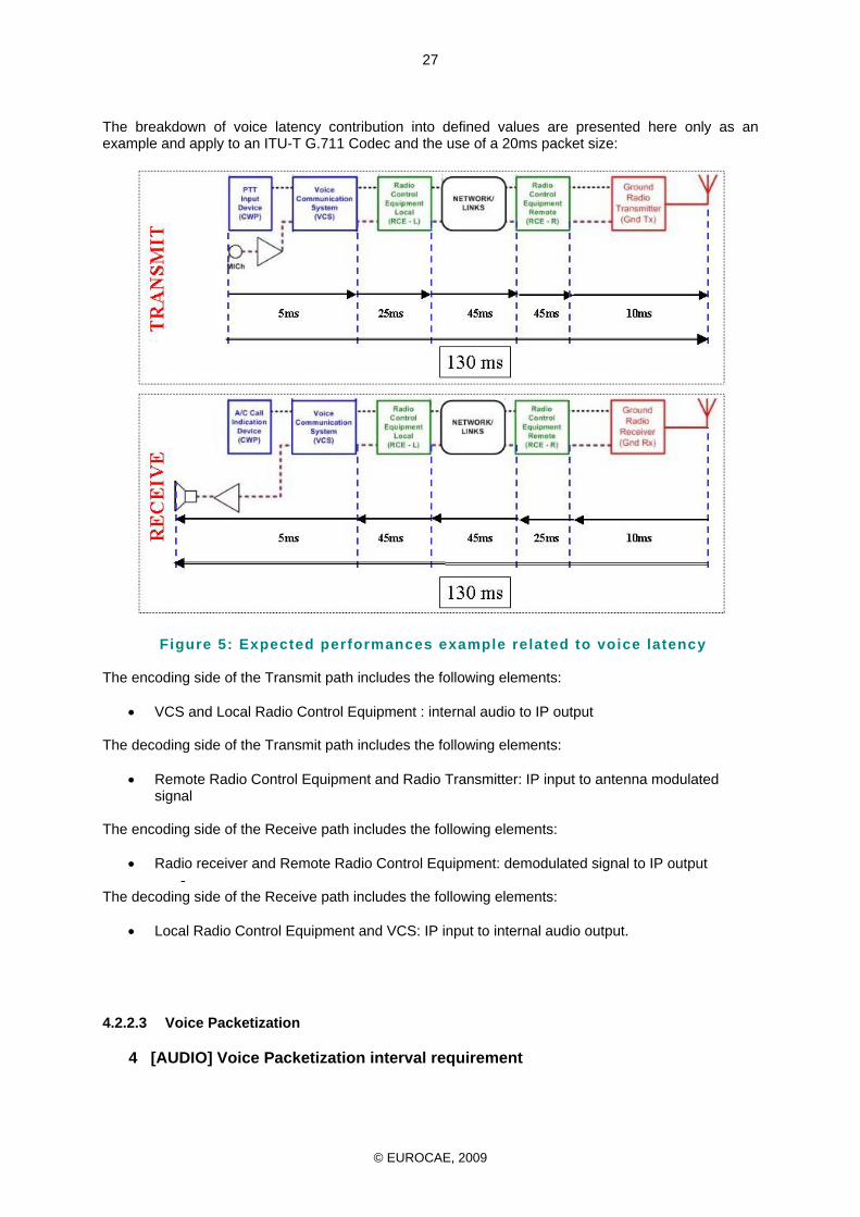
© EUROCAE, 2009
27
The breakdown of voice latency contribution into defined values are presented here only as an example and apply to an ITU-T G.711 Codec and the use of a 20ms packet size:
Figure 5: Expected performances example related to voice latency The encoding side of the Transmit path includes the following elements:
• VCS and Local Radio Control Equipment : internal audio to IP output The decoding side of the Transmit path includes the following elements:
• Remote Radio Control Equipment and Radio Transmitter: IP input to antenna modulated signal
The encoding side of the Receive path includes the following elements:
• Radio receiver and Remote Radio Control Equipment: demodulated signal to IP output -
The decoding side of the Receive path includes the following elements:
• Local Radio Control Equipment and VCS: IP input to internal audio output.
4.2.2.3 Voice Packetization
4 [AUDIO] Voice Packetization interval requirement
© EUROCAE, 2009
28
The VCS and Radio Equipment SHALL operate with 10, 20, 30 ms packet sizes. The size of the packet SHALL be defined during the SIP session negotiation The default packetization interval SHALL have a duration of 20 ms
4.2.2.4 Support for Audio side tone at the operator position level
5 [AUDIO] Side tone control requirement
The Audio side tone occurs when a PTT activation signal sent by a controller to activate the transmitter provide an audio signal which is returned at the VCS side to the controller on the receive path in order to confirm the voice transmission. A delay in the audio signal being returned can disturb the controller, in the case that it exceeds 10ms approximately. Audio side tone control devices SHALL be activated when the delay exceeds 10 ms.
4.2.3 Voice Coding
6 [AUDIO] Voice coding requirement
• The Voice SHALL be coded according to ITU-T G.711 A-law or µ-law. G.711 is the basic companding algorithm used for the voice transport application in the communication world. It is considered as the benchmark for digitally encoded voice quality against which other Voice Coding and Voice Compression algorithms are measured.
• In order to improve robustness, the ITU-T G.711PLC codec [35] SHOULD be used
• Should voice compression be required, the ITU-T G.728 [36] LD-CELP algorithm SHOULD be used;
• Should voice compression be required, the ITU-T G.729 [37] CS-ACELP algorithm SHOULD be used.
4.3 GUIDELINES FOR SAMPLE-BASED AUDIO CODECS
Among others, the RFC 3551 [23] standard defines the following guidelines for sample-based audio codecs:
• An RTP voice packet MAY contain any number of voice samples, subject to the constraint that the number of bits per sample multiplied by the number of samples per packet yields an integral octet count.
• The RTP timestamp reflects the instant at which the first sample in the packet was sampled,
that is, the oldest information in the packet.
4.4 AUDIO CODECS
The Audio codecs shown in Table 7 below are defined by RFC 3551 [23]. The payload type numbers are defined as shown by Table 11 below.
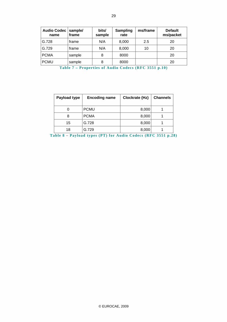
© EUROCAE, 2009
29
Audio Codec name
sample/ frame
bits/ sample
Sampling rate
ms/frame Default ms/packet
G.728 frame N/A 8,000 2.5 20
G.729 frame N/A 8,000 10 20
PCMA sample 8 8000 20
PCMU sample 8 8000 20 Table 7 – Propert ies of Audio Codecs (RFC 3551 p.10)
Payload type Encoding name Clockrate (Hz) Channels
0 PCMU 8,000 1
8 PCMA 8,000 1
15 G.728 8,000 1
18 G.729 8,000 1 Table 8 – Payload types (PT) for Audio Codecs (RFC 3551 p.28)
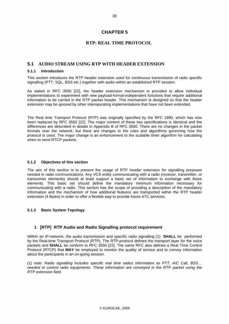
© EUROCAE, 2009
30
CHAPTER 5
RTP: REAL TIME PROTOCOL
5.1 AUDIO STREAM USING RTP WITH HEADER EXTENSION 5.1.1 Introduction
This section introduces the RTP header extension used for continuous transmission of radio specific signalling (PTT, SQL, BSS etc.) together with audio within an established RTP session. As stated in RFC 3550 [22], the header extension mechanism is provided to allow individual implementations to experiment with new payload-format-independent functions that require additional information to be carried in the RTP packet header. This mechanism is designed so that the header extension may be ignored by other interoperating implementations that have not been extended. The Real time Transport Protocol (RTP) was originally specified by the RFC 1890, which has now been replaced by RFC 3550 [22]. The major content of these two specifications is identical and the differences are described in details in Appendix B of RFC 3550. There are no changes in the packet formats over the network, but there are changes to the rules and algorithms governing how the protocol is used. The major change is an enhancement to the scalable timer algorithm for calculating when to send RTCP packets.
5.1.2 Objectives of this section
The aim of this section is to present the usage of RTP header extension for signalling purposes needed in radio communications. Any VCS entity communicating with a radio (receiver, transmitter, or transceiver elements) should at least support a basic set of information to exchange with these elements. This basic set should define the mandatory minimum information necessary for communicating with a radio. This section has the scope of providing a description of the mandatory information and the mechanism of how additional features are transported within the RTP header extension (4 Bytes) in order to offer a flexible way to provide future ATC services.
5.1.3 Basic System Topology
1 [RTP] RTP Audio and Radio Signalling protocol requirement
Within an IP-network, the audio transmission and specific radio signalling (1) SHALL be performed by the Real-time Transport Protocol (RTP). The RTP-protocol defines the transport layer for the voice packets and SHALL be conform to RFC 3550 [22]. The same RFC also defines a Real Time Control Protocol (RTCP) that MAY be employed to monitor the quality of service and to convey information about the participants in an on-going session. (1) note: Radio signalling includes specific real time radios information as PTT, A/C Call, BSS… needed to control radio equipments. These information are conveyed in the RTP packet using the RTP extension field.
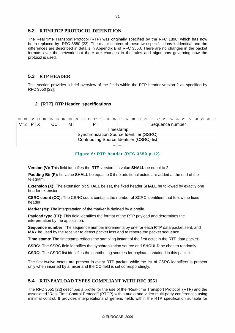
© EUROCAE, 2009
31
5.2 RTP/RTCP PROTOCOL DEFINITION
The Real time Transport Protocol (RTP) was originally specified by the RFC 1890, which has now been replaced by RFC 3550 [22]. The major content of these two specifications is identical and the differences are described in details in Appendix B of RFC 3550. There are no changes in the packet formats over the network, but there are changes to the rules and algorithms governing how the protocol is used.
5.3 RTP HEADER
This section provides a brief overview of the fields within the RTP header version 2 as specified by RFC 3550 [22]:
2 [RTP] RTP Header specifications
00 01 02 03 04 05 06 07 08 09 10 11 12 13 14 15 16 17 18 19 20 21 22 23 24 25 26 27 28 29 30 31
V=2 P X CC M PT Sequence number Timestamp
Synchronization Source Identifier (SSRC) Contributing Source Identifier (CSRC) list
........
Figure 6: RTP header (RFC 3550 p.12)
Version (V): This field identifies the RTP version. Its value SHALL be equal to 2.
Padding-Bit (P): Its value SHALL be equal to 0 if no additional octets are added at the end of the telegram.
Extension (X): The extension bit SHALL be set, the fixed header SHALL be followed by exactly one header extension
CSRC count (CC): The CSRC count contains the number of SCRC identifiers that follow the fixed header.
Marker (M): The interpretation of the marker is defined by a profile.
Payload type (PT): This field identifies the format of the RTP payload and determines the interpretation by the application.
Sequence number: The sequence number increments by one for each RTP data packet sent, and MAY be used by the receiver to detect packet loss and to restore the packet sequence.
Time stamp: The timestamp reflects the sampling instant of the first octet in the RTP data packet.
SSRC: The SSRC field identifies the synchronization source and SHOULD be chosen randomly
CSRC: The CSRC list identifies the contributing sources for payload contained in this packet. The first twelve octets are present in every RTP packet, while the list of CSRC identifiers is present only when inserted by a mixer and the CC-field is set correspondingly.
5.4 RTP-PAYLOAD TYPES COMPLIANT WITH RFC 3551
The RFC 3551 [22] describes a profile for the use of the “Real-time Transport Protocol” (RTP) and the associated “Real Time Control Protocol” (RTCP) within audio and video multi-party conferences using minimal control. It provides interpretations of generic fields within the RTP specification suitable for
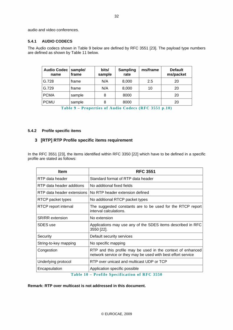
© EUROCAE, 2009
32
audio and video conferences.
5.4.1 AUDIO CODECS
The Audio codecs shown in Table 9 below are defined by RFC 3551 [23]. The payload type numbers are defined as shown by Table 11 below.
Audio Codec name
sample/ frame
bits/ sample
Sampling rate
ms/frame Default ms/packet
G.728 frame N/A 8,000 2.5 20
G.729 frame N/A 8,000 10 20
PCMA sample 8 8000 20
PCMU sample 8 8000 20 Table 9 – Propert ies of Audio Codecs (RFC 3551 p.10)
5.4.2 Profile specific items
3 [RTP] RTP Profile specific items requirement
In the RFC 3551 [23], the items identified within RFC 3350 [22] which have to be defined in a specific profile are stated as follows:
Item RFC 3551 RTP data header Standard format of RTP data header
RTP data header additions No additional fixed fields
RTP data header extensions No RTP header extension defined
RTCP packet types No additional RTCP packet types
RTCP report interval The suggested constants are to be used for the RTCP report interval calculations.
SR/RR extension No extension
SDES use Applications may use any of the SDES items described in RFC 3550 [22].
Security Default security services
String-to-key mapping No specific mapping
Congestion RTP and this profile may be used in the context of enhanced network service or they may be used with best effort service
Underlying protocol RTP over unicast and multicast UDP or TCP
Encapsulation Application specific possible Table 10 – Prof i le Specif icat ion of RFC 3550
Remark: RTP over multicast is not addressed in this document.
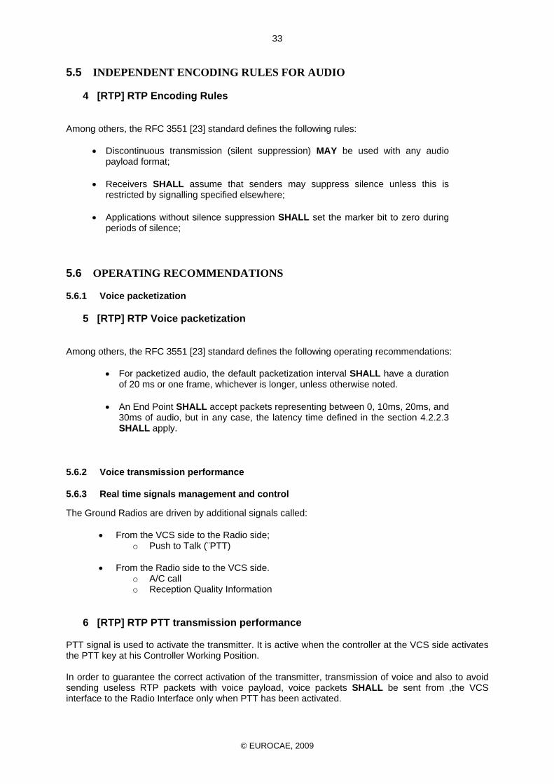
© EUROCAE, 2009
33
5.5 INDEPENDENT ENCODING RULES FOR AUDIO
4 [RTP] RTP Encoding Rules
Among others, the RFC 3551 [23] standard defines the following rules:
• Discontinuous transmission (silent suppression) MAY be used with any audio payload format;
• Receivers SHALL assume that senders may suppress silence unless this is restricted by signalling specified elsewhere;
• Applications without silence suppression SHALL set the marker bit to zero during periods of silence;
5.6 OPERATING RECOMMENDATIONS
5.6.1 Voice packetization
5 [RTP] RTP Voice packetization
Among others, the RFC 3551 [23] standard defines the following operating recommendations:
• For packetized audio, the default packetization interval SHALL have a duration of 20 ms or one frame, whichever is longer, unless otherwise noted.
• An End Point SHALL accept packets representing between 0, 10ms, 20ms, and 30ms of audio, but in any case, the latency time defined in the section 4.2.2.3 SHALL apply.
5.6.2 Voice transmission performance
5.6.3 Real time signals management and control
The Ground Radios are driven by additional signals called:
• From the VCS side to the Radio side; o Push to Talk (¨PTT)
• From the Radio side to the VCS side. o A/C call o Reception Quality Information
6 [RTP] RTP PTT transmission performance
PTT signal is used to activate the transmitter. It is active when the controller at the VCS side activates the PTT key at his Controller Working Position. In order to guarantee the correct activation of the transmitter, transmission of voice and also to avoid sending useless RTP packets with voice payload, voice packets SHALL be sent from ,the VCS interface to the Radio Interface only when PTT has been activated.
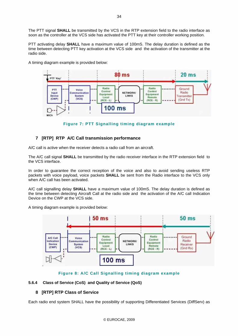
© EUROCAE, 2009
34
The PTT signal SHALL be transmitted by the VCS in the RTP extension field to the radio interface as soon as the controller at the VCS side has activated the PTT key at their controller working position. PTT activating delay SHALL have a maximum value of 100mS. The delay duration is defined as the time between detecting PTT key activation at the VCS side and the activation of the transmitter at the radio side.
A timing diagram example is provided below:
Figure 7: PTT Signall ing t iming diagram example
7 [RTP] RTP A/C Call transmission performance
A/C call is active when the receiver detects a radio call from an aircraft. The A/C call signal SHALL be transmitted by the radio receiver interface in the RTP extension field to the VCS interface. In order to guarantee the correct reception of the voice and also to avoid sending useless RTP packets with voice payload, voice packets SHALL be sent from the Radio interface to the VCS only when A/C call has been activated. A/C call signalling delay SHALL have a maximum value of 100mS. The delay duration is defined as the time between detecting Aircraft Call at the radio side and the activation of the A/C call Indication Device on the CWP at the VCS side. A timing diagram example is provided below:
Figure 8: A/C Call Signall ing t iming diagram example
5.6.4 Class of Service (CoS) and Quality of Service (QoS)
8 [RTP] RTP Class of Service
Each radio end system SHALL have the possibility of supporting Differentiated Services (DiffServ) as
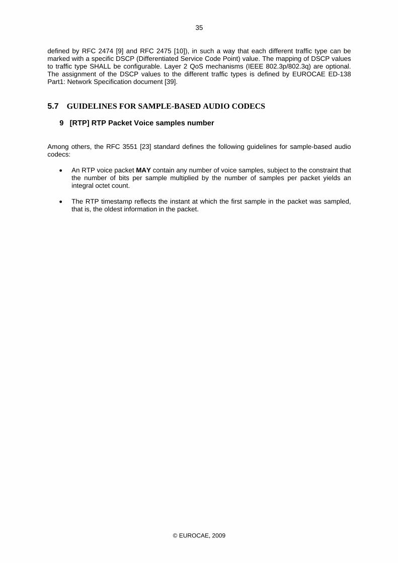
© EUROCAE, 2009
35
defined by RFC 2474 [9] and RFC 2475 [10]), in such a way that each different traffic type can be marked with a specific DSCP (Differentiated Service Code Point) value. The mapping of DSCP values to traffic type SHALL be configurable. Layer 2 QoS mechanisms (IEEE 802.3p/802.3q) are optional. The assignment of the DSCP values to the different traffic types is defined by EUROCAE ED-138 Part1: Network Specification document [39].
5.7 GUIDELINES FOR SAMPLE-BASED AUDIO CODECS
9 [RTP] RTP Packet Voice samples number
Among others, the RFC 3551 [23] standard defines the following guidelines for sample-based audio codecs:
• An RTP voice packet MAY contain any number of voice samples, subject to the constraint that the number of bits per sample multiplied by the number of samples per packet yields an integral octet count.
• The RTP timestamp reflects the instant at which the first sample in the packet was sampled,
that is, the oldest information in the packet.
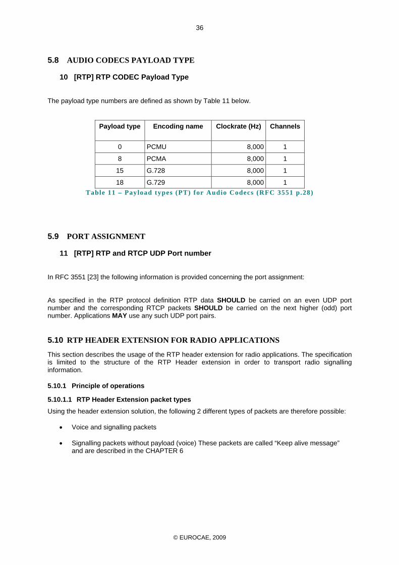
© EUROCAE, 2009
36
5.8 AUDIO CODECS PAYLOAD TYPE
10 [RTP] RTP CODEC Payload Type
The payload type numbers are defined as shown by Table 11 below.
Payload type Encoding name Clockrate (Hz) Channels
0 PCMU 8,000 1
8 PCMA 8,000 1
15 G.728 8,000 1
18 G.729 8,000 1 Table 11 – Payload types (PT) for Audio Codecs (RFC 3551 p.28)
5.9 PORT ASSIGNMENT
11 [RTP] RTP and RTCP UDP Port number
In RFC 3551 [23] the following information is provided concerning the port assignment: As specified in the RTP protocol definition RTP data SHOULD be carried on an even UDP port number and the corresponding RTCP packets SHOULD be carried on the next higher (odd) port number. Applications MAY use any such UDP port pairs.
5.10 RTP HEADER EXTENSION FOR RADIO APPLICATIONS
This section describes the usage of the RTP header extension for radio applications. The specification is limited to the structure of the RTP Header extension in order to transport radio signalling information.
5.10.1 Principle of operations
5.10.1.1 RTP Header Extension packet types
Using the header extension solution, the following 2 different types of packets are therefore possible:
• Voice and signalling packets
• Signalling packets without payload (voice) These packets are called “Keep alive message” and are described in the CHAPTER 6
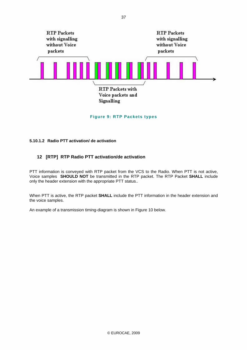
© EUROCAE, 2009
37
Figure 9: RTP Packets types
5.10.1.2 Radio PTT activation/ de activation
12 [RTP] RTP Radio PTT activation/de activation
PTT information is conveyed with RTP packet from the VCS to the Radio. When PTT is not active, Voice samples SHOULD NOT be transmitted in the RTP packet. The RTP Packet SHALL include only the header extension with the appropriate PTT status.. When PTT is active, the RTP packet SHALL include the PTT information in the header extension and the voice samples. An example of a transmission timing-diagram is shown in Figure 10 below.
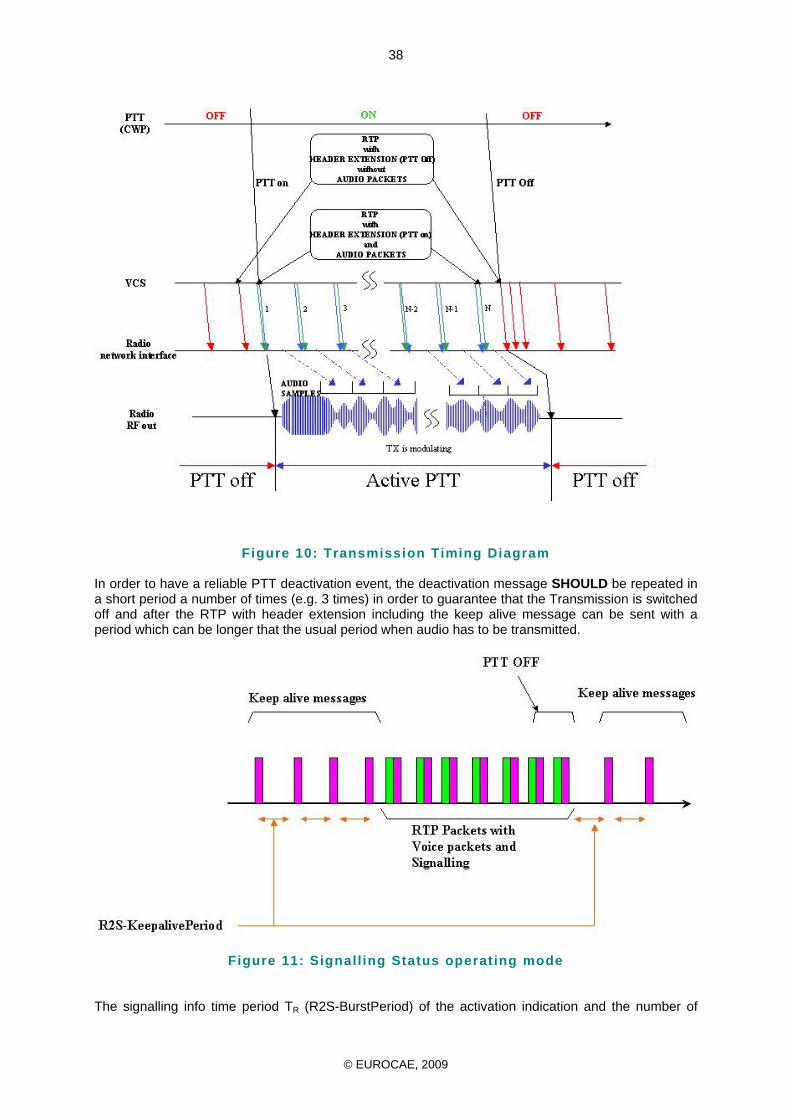
© EUROCAE, 2009
38
Figure 10: Transmission Timing Diagram
In order to have a reliable PTT deactivation event, the deactivation message SHOULD be repeated in a short period a number of times (e.g. 3 times) in order to guarantee that the Transmission is switched off and after the RTP with header extension including the keep alive message can be sent with a period which can be longer that the usual period when audio has to be transmitted.
Figure 11: Signall ing Status operating mode The signalling info time period TR (R2S-BurstPeriod) of the activation indication and the number of
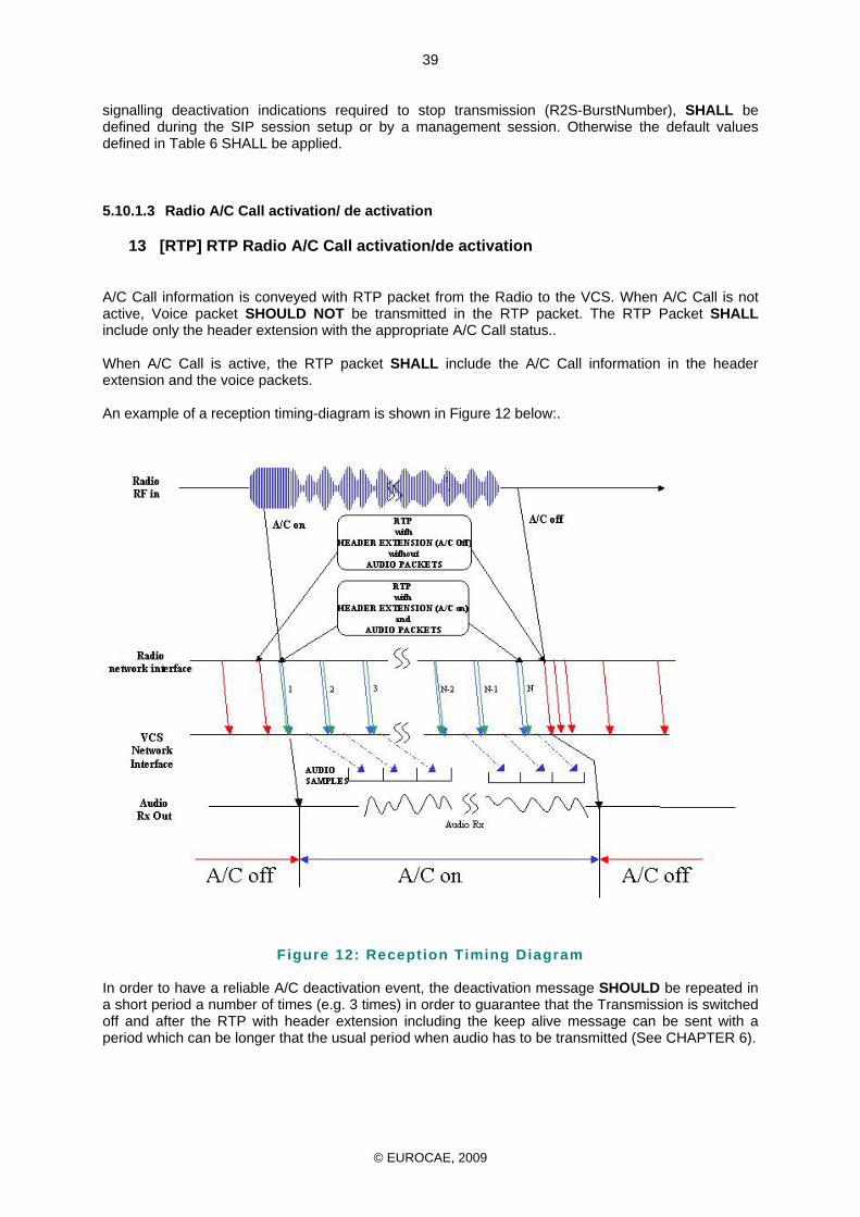
© EUROCAE, 2009
39
signalling deactivation indications required to stop transmission (R2S-BurstNumber), SHALL be defined during the SIP session setup or by a management session. Otherwise the default values defined in Table 6 SHALL be applied.
5.10.1.3 Radio A/C Call activation/ de activation
13 [RTP] RTP Radio A/C Call activation/de activation
A/C Call information is conveyed with RTP packet from the Radio to the VCS. When A/C Call is not active, Voice packet SHOULD NOT be transmitted in the RTP packet. The RTP Packet SHALL include only the header extension with the appropriate A/C Call status.. When A/C Call is active, the RTP packet SHALL include the A/C Call information in the header extension and the voice packets. An example of a reception timing-diagram is shown in Figure 12 below:.
Figure 12: Reception Timing Diagram
In order to have a reliable A/C deactivation event, the deactivation message SHOULD be repeated in a short period a number of times (e.g. 3 times) in order to guarantee that the Transmission is switched off and after the RTP with header extension including the keep alive message can be sent with a period which can be longer that the usual period when audio has to be transmitted (See CHAPTER 6).
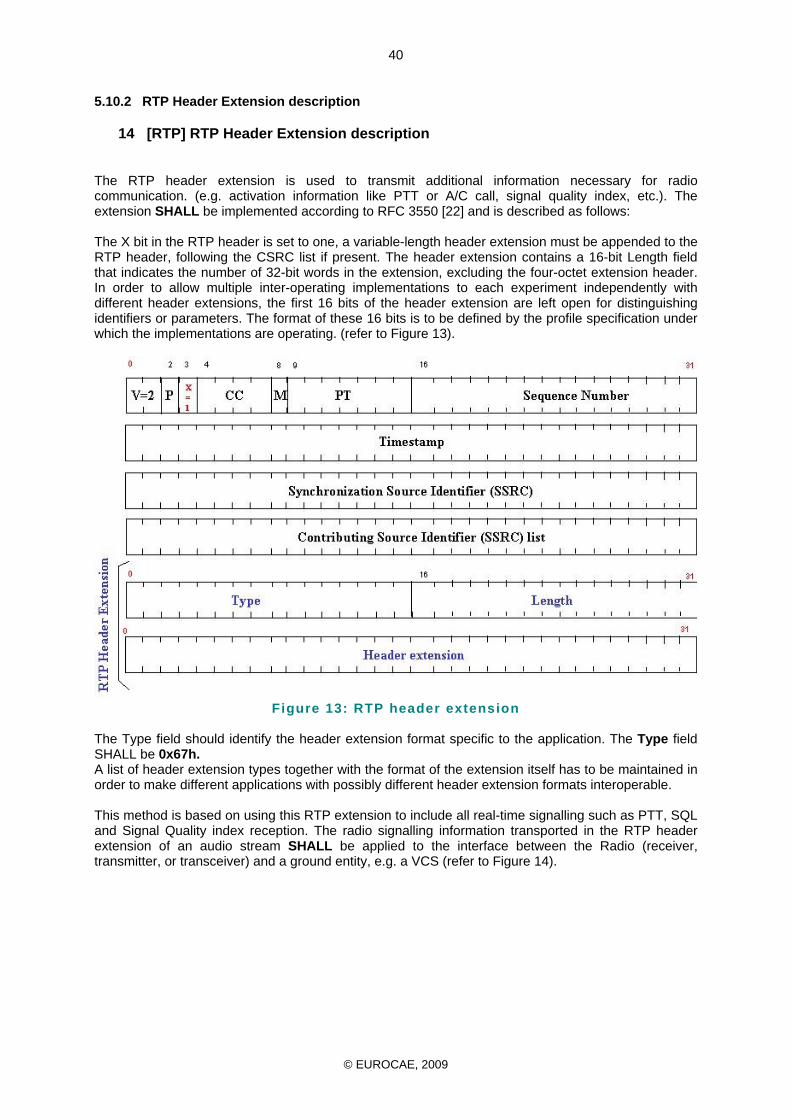
© EUROCAE, 2009
40
5.10.2 RTP Header Extension description
14 [RTP] RTP Header Extension description
The RTP header extension is used to transmit additional information necessary for radio communication. (e.g. activation information like PTT or A/C call, signal quality index, etc.). The extension SHALL be implemented according to RFC 3550 [22] and is described as follows: The X bit in the RTP header is set to one, a variable-length header extension must be appended to the RTP header, following the CSRC list if present. The header extension contains a 16-bit Length field that indicates the number of 32-bit words in the extension, excluding the four-octet extension header. In order to allow multiple inter-operating implementations to each experiment independently with different header extensions, the first 16 bits of the header extension are left open for distinguishing identifiers or parameters. The format of these 16 bits is to be defined by the profile specification under which the implementations are operating. (refer to Figure 13).
Figure 13: RTP header extension
The Type field should identify the header extension format specific to the application. The Type field SHALL be 0x67h. A list of header extension types together with the format of the extension itself has to be maintained in order to make different applications with possibly different header extension formats interoperable. This method is based on using this RTP extension to include all real-time signalling such as PTT, SQL and Signal Quality index reception. The radio signalling information transported in the RTP header extension of an audio stream SHALL be applied to the interface between the Radio (receiver, transmitter, or transceiver) and a ground entity, e.g. a VCS (refer to Figure 14).
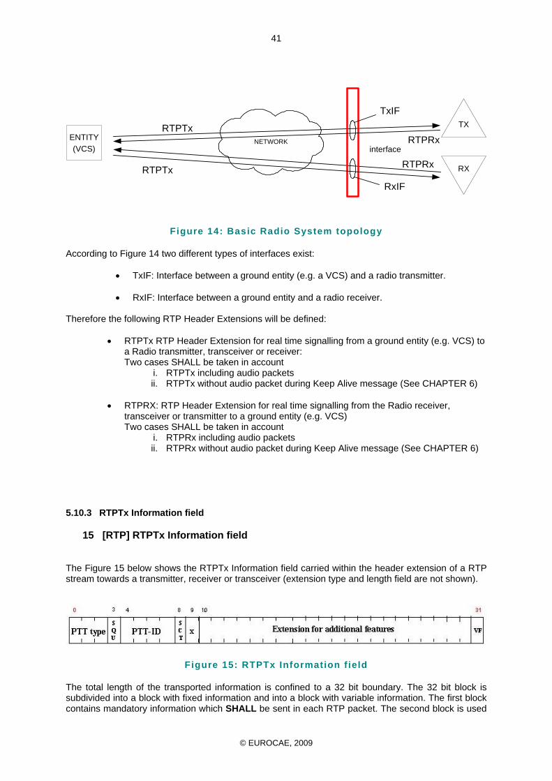
© EUROCAE, 2009
41
Figure 14: Basic Radio System topology According to Figure 14 two different types of interfaces exist:
• TxIF: Interface between a ground entity (e.g. a VCS) and a radio transmitter. • RxIF: Interface between a ground entity and a radio receiver.
Therefore the following RTP Header Extensions will be defined:
• RTPTx RTP Header Extension for real time signalling from a ground entity (e.g. VCS) to a Radio transmitter, transceiver or receiver: Two cases SHALL be taken in account
i. RTPTx including audio packets ii. RTPTx without audio packet during Keep Alive message (See CHAPTER 6)
• RTPRX: RTP Header Extension for real time signalling from the Radio receiver,
transceiver or transmitter to a ground entity (e.g. VCS) Two cases SHALL be taken in account
i. RTPRx including audio packets ii. RTPRx without audio packet during Keep Alive message (See CHAPTER 6)
5.10.3 RTPTx Information field
15 [RTP] RTPTx Information field
The Figure 15 below shows the RTPTx Information field carried within the header extension of a RTP stream towards a transmitter, receiver or transceiver (extension type and length field are not shown).
Figure 15: RTPTx Information f ield The total length of the transported information is confined to a 32 bit boundary. The 32 bit block is subdivided into a block with fixed information and into a block with variable information. The first block contains mandatory information which SHALL be sent in each RTP packet. The second block is used
NETWORKENTITY(VCS)
RX
TX
interface
RTPTx
RTPRxRTPTx
RTPRx
TxIF
RxIF
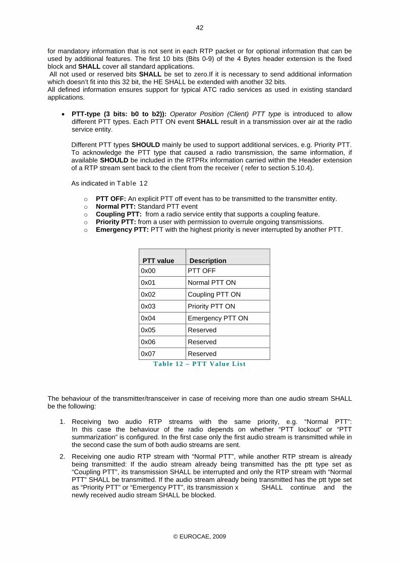
© EUROCAE, 2009
42
for mandatory information that is not sent in each RTP packet or for optional information that can be used by additional features. The first 10 bits (Bits 0-9) of the 4 Bytes header extension is the fixed block and SHALL cover all standard applications. All not used or reserved bits SHALL be set to zero.If it is necessary to send additional information which doesn’t fit into this 32 bit, the HE SHALL be extended with another 32 bits. All defined information ensures support for typical ATC radio services as used in existing standard applications.
• PTT-type (3 bits: b0 to b2)): Operator Position (Client) PTT type is introduced to allow different PTT types. Each PTT ON event SHALL result in a transmission over air at the radio service entity. Different PTT types SHOULD mainly be used to support additional services, e.g. Priority PTT. To acknowledge the PTT type that caused a radio transmission, the same information, if available SHOULD be included in the RTPRx information carried within the Header extension of a RTP stream sent back to the client from the receiver ( refer to section 5.10.4).
As indicated in Table 12
o PTT OFF: An explicit PTT off event has to be transmitted to the transmitter entity. o Normal PTT: Standard PTT event o Coupling PTT: from a radio service entity that supports a coupling feature. o Priority PTT: from a user with permission to overrule ongoing transmissions. o Emergency PTT: PTT with the highest priority is never interrupted by another PTT.
PTT value
Description
0x00 PTT OFF
0x01 Normal PTT ON
0x02 Coupling PTT ON
0x03 Priority PTT ON
0x04 Emergency PTT ON
0x05 Reserved
0x06 Reserved
0x07 Reserved Table 12 – PTT Value List
The behaviour of the transmitter/transceiver in case of receiving more than one audio stream SHALL be the following:
1. Receiving two audio RTP streams with the same priority, e.g. “Normal PTT”: In this case the behaviour of the radio depends on whether “PTT lockout” or “PTT summarization” is configured. In the first case only the first audio stream is transmitted while in the second case the sum of both audio streams are sent.
2. Receiving one audio RTP stream with “Normal PTT”, while another RTP stream is already being transmitted: If the audio stream already being transmitted has the ptt type set as “Coupling PTT”, its transmission SHALL be interrupted and only the RTP stream with “Normal PTT” SHALL be transmitted. If the audio stream already being transmitted has the ptt type set as “Priority PTT” or “Emergency PTT”, its transmission x SHALL continue and the newly received audio stream SHALL be blocked.
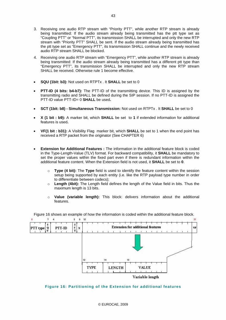
© EUROCAE, 2009
43
3. Receiving one audio RTP stream with “Priority PTT”, while another RTP stream is already being transmitted: If the audio stream already being transmitted has the ptt type set as “Coupling PTT” or “Normal PTT”, its transmission SHALL be interrupted and only the new RTP stream with “Priority PTT” SHALL be sent. If the audio stream already being transmitted has the ptt type set as “Emergency PTT”, its transmission SHALL continue and the newly received audio RTP stream SHALL be blocked.
4. Receiving one audio RTP stream with “Emergency PTT”, while another RTP stream is already being transmitted: If the audio stream already being transmitted has a different ptt type than “Emergency PTT”, its transmission SHALL be interrupted and only the new RTP stream SHALL be received. Otherwise rule 1 become effective.
• SQU (1bit: b3): Not used on RTPTx . It SHALL be set to 0 • PTT-ID (4 bits: b4-b7): The PTT-ID of the transmitting device. This ID is assigned by the
transmitting radio and SHALL be defined during the SIP session. If no PTT-ID is assigned the PTT-ID value PTT-ID= 0 SHALL be used.
• SCT (1bit: b8) - Simultaneous Transmission: Not used on RTPTx . It SHALL be set to 0
• X (1 bit : b9): A marker bit, which SHALL be set to 1 if extended information for additional
features is used.
• VF(1 bit : b31): A Visibility Flag marker bit, which SHALL be set to 1 when the end point has received a RTP packet from the originator (See CHAPTER 6)
• Extension for Additional Features : The information in the additional feature block is coded
in the Type-Length-Value (TLV) format. For backward compatibility, it SHALL be mandatory to set the proper values within the fixed part even if there is redundant information within the additional feature content. When the Extension field is not used, it SHALL be set to 0.
o Type (4 bit): The Type field is used to identify the feature content within the session
setup being supported by each entity (i.e. like the RTP payload type number in order to differentiate between codecs);
o Length (4bit): The Length field defines the length of the Value field in bits. Thus the maximum length is 13 bits.
o Value (variable length): This block: delivers information about the additional
features.
Figure 16 shows an example of how the information is coded within the additional feature block.
Figure 16: Part it ioning of the Extension for addit ional features
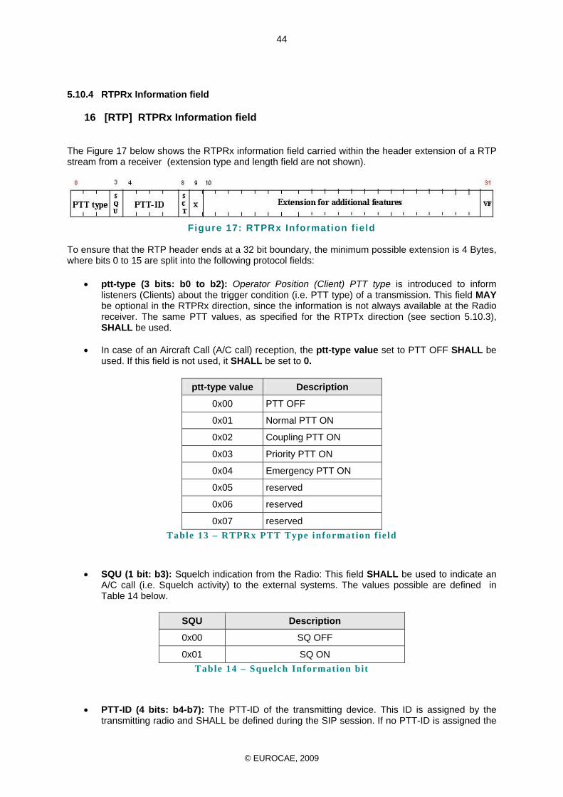
© EUROCAE, 2009
44
5.10.4 RTPRx Information field
16 [RTP] RTPRx Information field
The Figure 17 below shows the RTPRx information field carried within the header extension of a RTP stream from a receiver (extension type and length field are not shown).
Figure 17: RTPRx Information f ield
To ensure that the RTP header ends at a 32 bit boundary, the minimum possible extension is 4 Bytes, where bits 0 to 15 are split into the following protocol fields:
• ptt-type (3 bits: b0 to b2): Operator Position (Client) PTT type is introduced to inform
listeners (Clients) about the trigger condition (i.e. PTT type) of a transmission. This field MAY be optional in the RTPRx direction, since the information is not always available at the Radio receiver. The same PTT values, as specified for the RTPTx direction (see section 5.10.3), SHALL be used.
• In case of an Aircraft Call (A/C call) reception, the ptt-type value set to PTT OFF SHALL be
used. If this field is not used, it SHALL be set to 0.
ptt-type value Description
0x00 PTT OFF
0x01 Normal PTT ON
0x02 Coupling PTT ON
0x03 Priority PTT ON
0x04 Emergency PTT ON
0x05 reserved
0x06 reserved
0x07 reserved Table 13 – RTPRx PTT Type information f ield
• SQU (1 bit: b3): Squelch indication from the Radio: This field SHALL be used to indicate an
A/C call (i.e. Squelch activity) to the external systems. The values possible are defined in Table 14 below.
SQU Description
0x00 SQ OFF
0x01 SQ ON Table 14 – Squelch Information bit
• PTT-ID (4 bits: b4-b7): The PTT-ID of the transmitting device. This ID is assigned by the transmitting radio and SHALL be defined during the SIP session. If no PTT-ID is assigned the
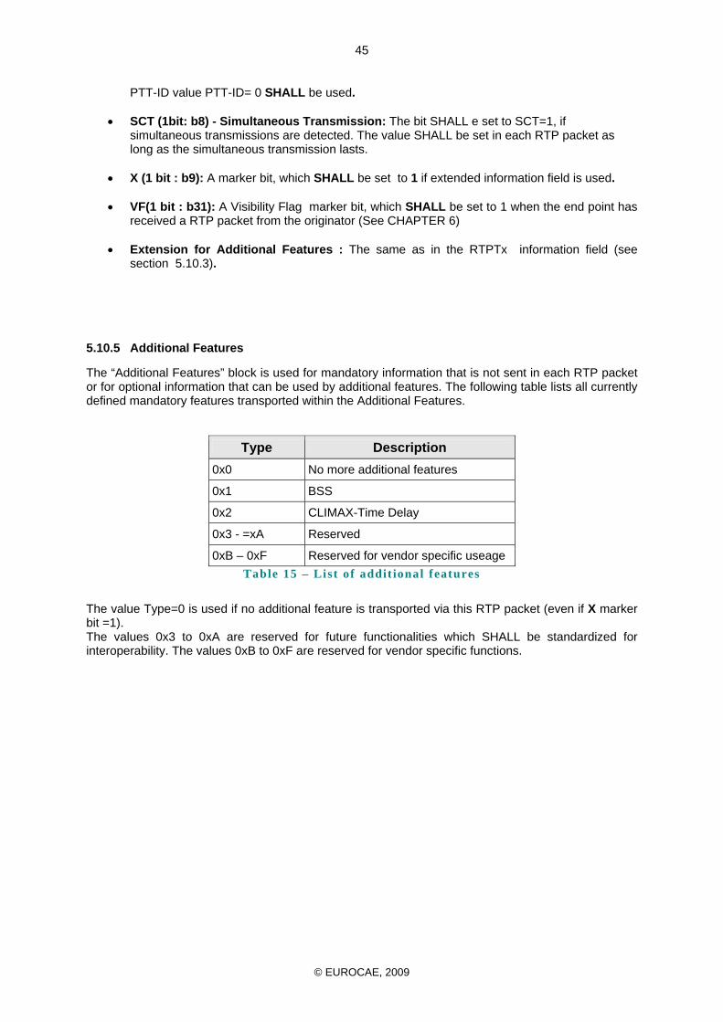
© EUROCAE, 2009
45
PTT-ID value PTT-ID= 0 SHALL be used. • SCT (1bit: b8) - Simultaneous Transmission: The bit SHALL e set to SCT=1, if
simultaneous transmissions are detected. The value SHALL be set in each RTP packet as long as the simultaneous transmission lasts.
• X (1 bit : b9): A marker bit, which SHALL be set to 1 if extended information field is used.
• VF(1 bit : b31): A Visibility Flag marker bit, which SHALL be set to 1 when the end point has
received a RTP packet from the originator (See CHAPTER 6)
• Extension for Additional Features : The same as in the RTPTx information field (see section 5.10.3).
5.10.5 Additional Features
The “Additional Features” block is used for mandatory information that is not sent in each RTP packet or for optional information that can be used by additional features. The following table lists all currently defined mandatory features transported within the Additional Features.
Type Description 0x0 No more additional features
0x1 BSS
0x2 CLIMAX-Time Delay
0x3 - =xA Reserved
0xB – 0xF Reserved for vendor specific useage Table 15 – List of addit ional features
The value Type=0 is used if no additional feature is transported via this RTP packet (even if X marker bit =1). The values 0x3 to 0xA are reserved for future functionalities which SHALL be standardized for interoperability. The values 0xB to 0xF are reserved for vendor specific functions.
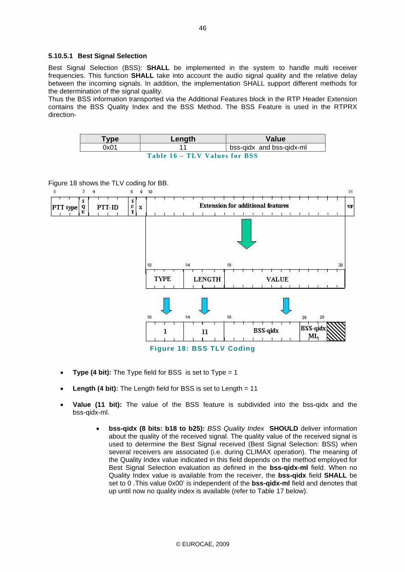
© EUROCAE, 2009
46
5.10.5.1 Best Signal Selection
Best Signal Selection (BSS): SHALL be implemented in the system to handle multi receiver frequencies. This function SHALL take into account the audio signal quality and the relative delay between the incoming signals. In addition, the implementation SHALL support different methods for the determination of the signal quality. Thus the BSS information transported via the Additional Features block in the RTP Header Extension contains the BSS Quality Index and the BSS Method. The BSS Feature is used in the RTPRX direction-
Type Length Value 0x01 11 bss-qidx and bss-qidx-ml
Table 16 – TLV Values for BSS
Figure 18 shows the TLV coding for BB.
Figure 18: BSS TLV Coding
• Type (4 bit): The Type field for BSS is set to Type = 1 • Length (4 bit): The Length field for BSS is set to Length = 11
• Value (11 bit): The value of the BSS feature is subdivided into the bss-qidx and the
bss-qidx-ml.
• bss-qidx (8 bits: b18 to b25): BSS Quality Index SHOULD deliver information about the quality of the received signal. The quality value of the received signal is used to determine the Best Signal received (Best Signal Selection: BSS) when several receivers are associated (i.e. during CLIMAX operation). The meaning of the Quality Index value indicated in this field depends on the method employed for Best Signal Selection evaluation as defined in the bss-qidx-ml field. When no Quality Index value is available from the receiver, the bss-qidx field SHALL be set to 0 .This value 0x00’ is independent of the bss-qidx-ml field and denotes that up until now no quality index is available (refer to Table 17 below).
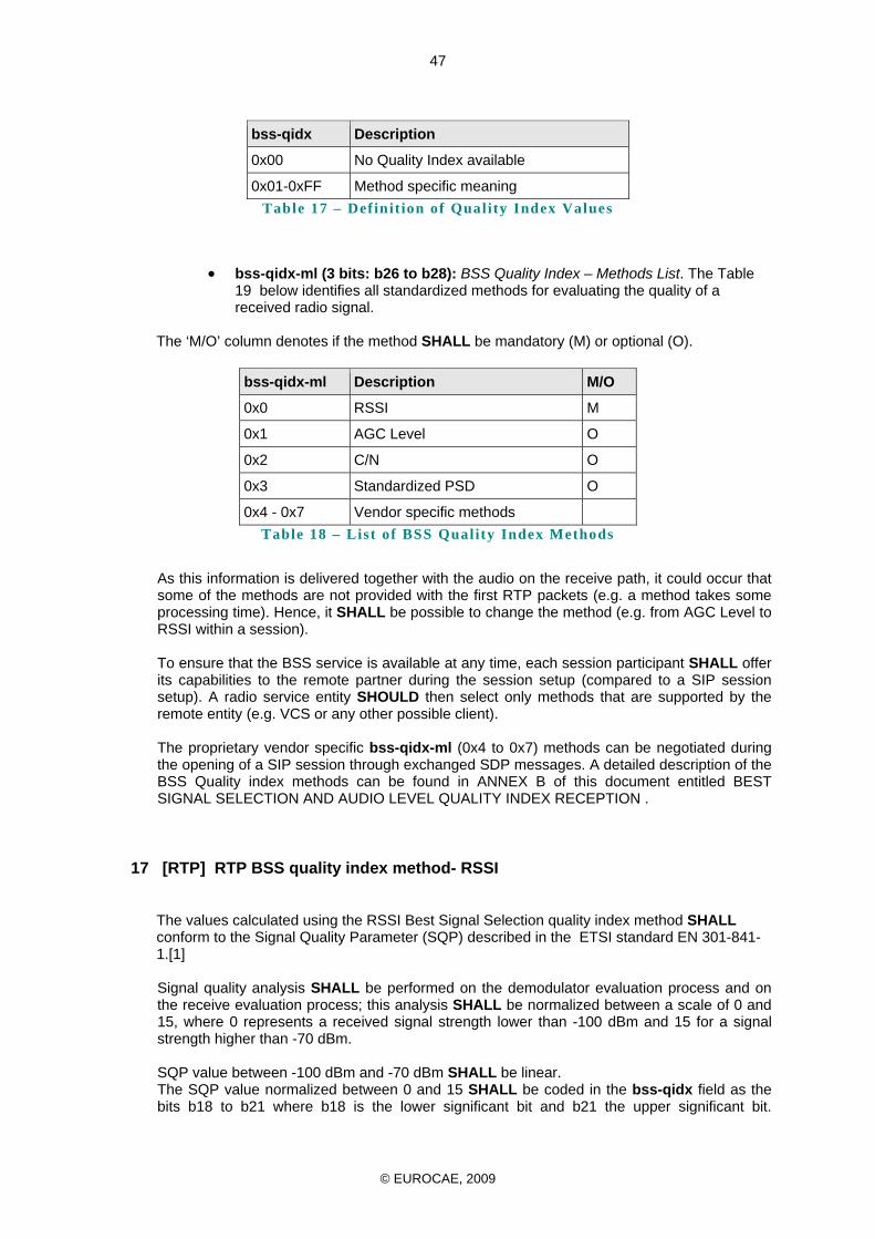
© EUROCAE, 2009
47
bss-qidx Description
0x00 No Quality Index available
0x01-0xFF Method specific meaning Table 17 – Def init ion of Quality Index Values
• bss-qidx-ml (3 bits: b26 to b28): BSS Quality Index – Methods List. The Table 19 below identifies all standardized methods for evaluating the quality of a received radio signal.
The ‘M/O’ column denotes if the method SHALL be mandatory (M) or optional (O).
bss-qidx-ml Description M/O
0x0 RSSI M
0x1 AGC Level O
0x2 C/N O
0x3 Standardized PSD O
0x4 - 0x7 Vendor specific methods Table 18 – List of BSS Quality Index Methods
As this information is delivered together with the audio on the receive path, it could occur that some of the methods are not provided with the first RTP packets (e.g. a method takes some processing time). Hence, it SHALL be possible to change the method (e.g. from AGC Level to RSSI within a session). To ensure that the BSS service is available at any time, each session participant SHALL offer its capabilities to the remote partner during the session setup (compared to a SIP session setup). A radio service entity SHOULD then select only methods that are supported by the remote entity (e.g. VCS or any other possible client). The proprietary vendor specific bss-qidx-ml (0x4 to 0x7) methods can be negotiated during the opening of a SIP session through exchanged SDP messages. A detailed description of the BSS Quality index methods can be found in ANNEX B of this document entitled BEST SIGNAL SELECTION AND AUDIO LEVEL QUALITY INDEX RECEPTION .
17 [RTP] RTP BSS quality index method- RSSI
The values calculated using the RSSI Best Signal Selection quality index method SHALL conform to the Signal Quality Parameter (SQP) described in the ETSI standard EN 301-841-1.[1] Signal quality analysis SHALL be performed on the demodulator evaluation process and on the receive evaluation process; this analysis SHALL be normalized between a scale of 0 and 15, where 0 represents a received signal strength lower than -100 dBm and 15 for a signal strength higher than -70 dBm. SQP value between -100 dBm and -70 dBm SHALL be linear. The SQP value normalized between 0 and 15 SHALL be coded in the bss-qidx field as the bits b18 to b21 where b18 is the lower significant bit and b21 the upper significant bit.
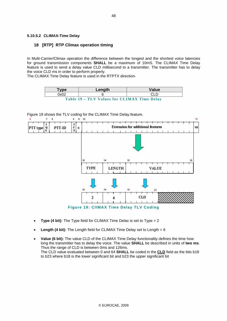
© EUROCAE, 2009
48
5.10.5.2 CLIMAX-Time Delay
18 [RTP] RTP Climax operation timing
In Multi-Carrier/Climax operation the difference between the longest and the shortest voice latencies for ground transmission components SHALL be a maximum of 10mS. The CLIMAX Time Delay feature is used to send a delay value CLD millisecond to a transmitter. The transmitter has to delay the voice CLD ms in order to perform properly. The CLIMAX Time Delay feature is used in the RTPTX direction-
Type Length Value 0x02 6 CLD
Table 19 – TLV Values for CLIMAX Time Delay
Figure 19 shows the TLV coding for the CLIMAX Time Delay.feature.
Figure 19: ClIMAX Time Delay TLV Coding
• Type (4 bit): The Type field for CLIMAX Time Delax is set to Type = 2 • Length (4 bit): The Length field for CLIMAX Time Delay set to Length = 6
• Value (6 bit): The value CLD of the CLIMAX Time Delay functionality defines the time how
long the transmitter has to delay the voice. The value SHALL be described in units of two ms. Thus the range of CLD is between 0ms and 126ms. The CLD value evaluated between 0 and 64 SHALL be coded in the CLD field as the bits b18 to b23 where b18 is the lower significant bit and b23 the upper significant bit
© EUROCAE, 2009
49
CHAPTER 6
6.1 Real Time Session Supervision 6.1.1 Introduction
The SIP provides no inherent mechanism for monitoring the status of the network link. Without a monitoring mechanism one session endpoint which is not receiving any packet will not be able to distinguish between the case when there are no packets issued by the sender and the case when packets issued by the sender are lost somewhere along the travelling path. The Real-time Session Supervision in short R2S comes in addition to every SIP established session in order to provide the endpoint the awareness about the reachability of the peer. The mechanism providing fault detection is employed by periodical exchange of signalling messages. Depending upon the “visibility” of the hello messages received The remarkable characteristic of R2S signalling messages is that these shares the same envelope with the voice stream associated to that session up to Layer 3 inclusive and therefore are indistinguishable one from another from network point of view. 6.1.2 Signalling message types
The signalling message is a chunk of data transmitted as extension of an RTP packet wrapped almost identically as the associated voice packet. There are six types of possible signalling messages depending of the originator and the destination of the message.
Message type Originator Destination Description 1 VTx VCS Transmitter Refreshing the status of PTT to the transmitter 2 TxV Transmitter VCS Transmitting the status of the transmitter to VCS 3 VRx VCS Receiver Transmitting mainly the visibility flag b31 4 RxV Receiver VCS Refreshing the status of the receiver to VCS 5 RxTx Receiver Transmitter Refreshing the status of the receiver to the transmitter
(Optional) 6 TxRx Transmitter Receiver Refreshing the status of the transmitter to the receiver
(optional) Table 20 – Keep al ive messages possible interconnect ions
For all this messages the bit b31 of the RTP extender field is the visibility flag (VF) VF bit is included in the Header Extender of the RTP signalling sent with or without voice. When session is established between two end points A and B, each of the endpoint send a RTP stream periodically. The Visibility Flag (VF) included in the header extension field is set as soon as an endpoint is receiving a RTP stream from the other Endpoint. As long as an endpoint does not receive any RTP stream from the other endpoint, VF is reset 6.1.3 R2S Keep Alive Signalling Operation
19 [RTP] Keepalive messages
The Keep alive signalling message is a RTP packet with the following specifications. X=1 PT=123 (dynamic) No RTCP reports are issued for this type of payload. There is an exception when PT will not have the value of 123 but instead will indicate the codec associated to the voice samples. See “Signalling Operations” chapter.
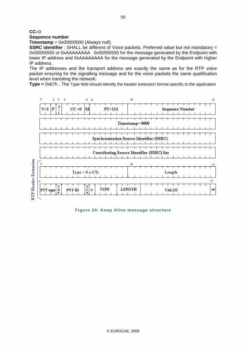
© EUROCAE, 2009
50
CC=0 Sequence number Timestamp = 0x00000000 (Always null). SSRC identifier : SHALL be different of Voice packets. Preferred value but not mandatory = 0x55555555 or 0xAAAAAAAA. 0x55555555 for the message generated by the Endpoint with lower IP address and 0xAAAAAAAA for the message generated by the Endpoint with higher IP address. The IP addresses and the transport address are exactly the same as for the RTP voice packet ensuring for the signalling message and for the voice packets the same qualification level when transiting the network. Type = 0x67h . The Type field should identify the header extension format specific to the application
Figure 20: Keep Alive message structure
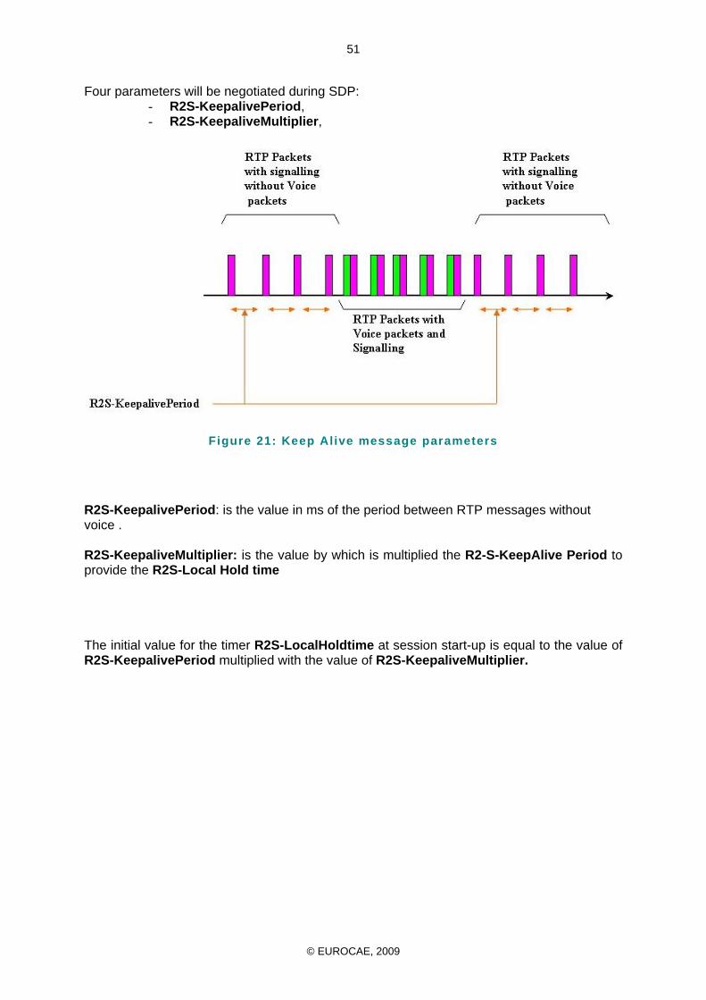
© EUROCAE, 2009
51
Four parameters will be negotiated during SDP: - R2S-KeepalivePeriod, - R2S-KeepaliveMultiplier,
Figure 21: Keep Alive message parameters
R2S-KeepalivePeriod: is the value in ms of the period between RTP messages without voice . R2S-KeepaliveMultiplier: is the value by which is multiplied the R2-S-KeepAlive Period to provide the R2S-Local Hold time The initial value for the timer R2S-LocalHoldtime at session start-up is equal to the value of R2S-KeepalivePeriod multiplied with the value of R2S-KeepaliveMultiplier.
© EUROCAE, 2009
52
A) Rule to transmit signalling messages: The signalling messages are to be sent with the cadence specified by the value R2S-KeepalivePeriod. When voice is present the signalling messages are sent as within the extension of the RTP header while the voice samples are sent as payload.
B) Rule for resetting the visibility flag, SIP session tearing down and setup retry:
When a signalling message from the corresponding Endpoint is received having the visibility flag value set to logical 1, the local timer R2S-LocalHoldtime is initialised. R2S-LocalHoldtime is initialised with the value of R2S-KeepaliveMultiplier The local timer R2S-LocalHoldtime is decremented by a unit every R2S-KeepalivePeriod message sent by the system as long as the Visibility Flag received from the other end point is reset or as long as no message is coming back from the other endpoint.. When the R2S-LocalHoldtime reach zero, the SIP session SHALL be released by sending the SIP BYE message. The SIP session will remain in the unacknowledged state until the SIP stack timers will expire or until an acknowledge message will arrive. The SIP initiator SHALL try to establish a new session immediately after the first BYE message of the previous session has been sent.
© EUROCAE, 2009
53
ANNEX A
REFERENCES [1] ETSI standard EN 301-841-1 [2] IETF RFC 768: User Datagram Protocol (UDP), August 1980. [3] IETF RFC 791: Internet Protocol” (IP) version 4, September 1981. [4] IETF RFC 793: Transmission Control Protocol (TCP), September 1981. [5] IETF RFC2104: HMAC: Keyed-Hashing for Message Authentication, February 1997. [6] IETF RFC 2119: Key words for use in RFCs to Indicate Requirement Levels, BCP 14, March
1997. [7] IETF RFC 2327: SDP: Session Description Protocol, April 1998. [8] IETF RFC 2460: Internet Protocol, Version 6 (IPv6) Specification, December 1998. [9] IETF RFC 2474: Definition of the Differentiated Services Field (DS Field) in the IPv4 and IPv6
Headers, December 1998. [10] IETF RFC 2475: An architecture for Differentiated Services, December 1998. [11] IETF RFC 2508: Compressing IP/UDP/RTP Headers for Low-Speed Serial Links, February
1999. [12] IETF RFC 3261: “SIP: Session Initiation Protocol”, June 2002. [13] IETF RFC 3262: “SIP: Reliability of Provisional Responses in the Session Initiation Protocol
(SIP)”, June 2002 [14] IETF RFC 3264: An Offer/Answer Model with the Session Description Protocol (SDP), June
2002. [15] IETF RFC 3265: Session Initiation Protocol (SIP)-Specific Event Notification, June 2002. [16] IETF RFC 3311: The Session Initiation Protocol (SIP) UPDATE Method, September 2002. [17] IETF RFC 3325: Private Extensions to the Session Initiation Protocol (SIP) for Asserted Identity
within Trusted Networks, November 2002. [18] IETF RFC 3411: An Architecture for Describing SNMP Management Frameworks;
[19] IETF RFC 3414: Virtual User-based Security Model (USM) for version 3 of the Simple Network
Management Protocol (SNMPv3), December 2002. [20] IETF RFC 3489 – STUN - Simple Traversal of User Datagram Protocol (UDP) Through Network
Address Translators (NATs), March 2003. [21] IETF RFC 3515: The Session Initiation Protocol (SIP) Refer Method, April 2003. [22] IETF RFC 3550: RTP: A Transport Protocol for Real-Time Applications, July 2003.
© EUROCAE, 2009
54
[23] IETF RFC 3551: RTP Profile for Audio and Video Conferences with Minimal Control, July 2003. [24] IETF RFC 3665: Session Initiation Protocol (SIP) Basic Call Flow Examples, December 2003. [25] IETF RFC 3711: The Secure Real-Time Transport Protocol (SRTP), March 2004. [26] IETF RFC 3768: Virtual Router Redundancy Protocol (VRRP), April 2004. [27] IETF RFC 3840: Indicating User Agent Capabilities in the Session Initiation Protocol (SIP),
August 2004. [28] IETF RFC 3891: Session Inititation Protocol (SIP) “Replaces” Header, September 2004. [29] IETF RFC 3911: Session Inititation Protocol (SIP) “Join Header”, October 2004. [30] IETF RFC3916: Requirements for Pseudo-Wire Emulation Edge-to-Edge (PWE3), September
2004. [31] IETF RFC 4235: An INVITE-Initiated Dialog Event Package for the Session Initiation Protocol
(SIP), November 2005. [32] IETF RFC 4346: The Transport Layer Security (TLS) Protocol - Version 1.1, April 2006. [33] IETF RFC 4566: SDP: Session Description Protocol, July 2006. [34] EUROCONTROL. “Voice Communication System (VCS) Procurement Guidelines”, Ed. 2.0,
February 2005. [35] ITU-T. Rec. G.711. “Pulse Code Modulation (PCM) of Voice Frequencies”, November 1988. [36] ITU-T. Rec. G.728. “Coding of Speech at 16 Kbit/s Using Low-delay Code Excited Linear
Prediction”, September 1992. [37] ITU-T. Rec. G.729 “Coding of Speech Signals at 8 kbit/s using Conjugate- Structure Algebraic-
Code-Excited Linear-Prediction (CS-ACELP), January 2007. [38] EUROCAE ED-137 “Interoperability Standards for VoIP ATM Components, Part 2: Telephone” [39] EUROCAE ED-138 “Network Requirements and Performances for Voice over Internet Protocol
(VoIP) for Air Traffic Management (ATM) Systems” Part 1: Network Specification [40] EUROCAE WG67-2_V01_RTP_HEADER_EXTENTION – Frequentis GmBH [41] EUROCAE WG67_BSS_03_B – SELEX Communications
© EUROCAE, 2009
55
ANNEX B
BEST SIGNAL SELECTION AND AUDIO LEVEL QUALITY INDEX RECEPTION
B.1.1. Objectives of this Annex
The objective of this Annex is to provide a definition of Best Signal Selection (BSS) and a brief description of the most commonly used methods employed to perform it. This Annex considers BSS operation within an ATM environment and the use of IP networks for connecting the different infrastructures.
B.1.2. BSS definition
Within a radio system where there is more than one incoming signal source, it is necessary to select the best signal source available. The Best Signal Selection is an automatic method for selecting the best signal source at any instant. The BSS (also nominated Receiver Voting) is performed through the continuous monitoring of a parameter that is correlated to the quality of the received signal.
Comparing the magnitude of this parameter measured in each of the Rx paths allows the choice of Best Signal Selection to be made. The entity performing the Receiver voting can use a combination of multiple parameters in order to ensure that the signal with the best quality is selected.
B.1.2.1. Parameters
This section identifies which parameters can be employed in measuring the signal quality and at the same time easily permits calculations to be performed for real time monitoring.
In the receive path, between the antenna and operator console, it is possible to identify two main points where the signal quality estimation can be performed; the first is located at the Ground Station Computer, Controller (GSC) or Radio itself and the second is located within the Voice Communication System (VCS).
The main parameters that can be used for monitoring the quality of the signal are defined below:
RSSI: The Received Signal Strength Indication is a measure of the carrier’s energy, it is normally expressed in dBm and a dedicated circuit measures it. This circuit outputs an electrical signal or a numerical value proportional to the Received Signal Strength.
The RSSI can be used also for providing indications about the presence of activity on a Radio Channel. This functionality is used by the CSMA/CA (802.11) algorithm in order to check if a channel is free for starting a transmission.
The RSSI is normally evaluated at the IF stage within the RX equipment. When there is no IF stage the measurement is made directly at base-band level, where the DC level is proportional to the carrier amplitude.
With modern Receivers, that include microprocessors, Digital Signal Processors (DSP) and Ethernet connectivity, the processing power is powerful enough to calculate the RSSI in real Time.
Giving the RSSI directly, in dBm, no scale calibration is requested and consequently the provided value is absolute and manufacturer-independent.
C/N Ratio: The C/N ratio is measured in a manner similar to the way the signal-to-noise ratio (S/N) is measured, and both specifications give an indication of the quality of a communications channel. However, the S/N ratio specification is more meaningful in practical situations. The C/N ratio is commonly used in satellite communications systems to point or align the receiving dish; the best dish alignment is indicated by the maximum C/N ratio.
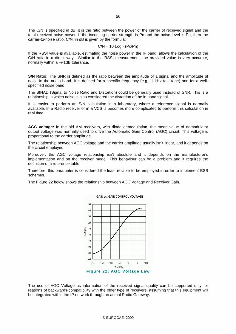
© EUROCAE, 2009
56
The C/N is specified in dB, it is the ratio between the power of the carrier of received signal and the total received noise power. If the incoming carrier strength is Pc and the noise level is Pn, then the carrier-to-noise ratio, C/N, in dB is given by the formula:
C/N = 10 Log10 (Pc/Pn)
If the RSSI value is available, estimating the noise power in the IF band, allows the calculation of the C/N ratio in a direct way. Similar to the RSSI measurement, the provided value is very accurate, normally within a +/-1dB tolerance.
S/N Ratio: The SNR is defined as the ratio between the amplitude of a signal and the amplitude of noise in the audio band. It is defined for a specific frequency (e.g., 1 kHz test tone) and for a well-specified noise band.
The SINAD (Signal to Noise Ratio and Distortion) could be generally used instead of SNR. This is a relationship in which noise is also considered the distortion of the in band signal.
It is easier to perform an S/N calculation in a laboratory, where a reference signal is normally available. In a Radio receiver or in a VCS is becomes more complicated to perform this calculation in real time.
AGC voltage: In the old AM receivers, with diode demodulation, the mean value of demodulator output voltage was normally used to drive the Automatic Gain Control (AGC) circuit. This voltage is proportional to the carrier amplitude.
The relationship between AGC voltage and the carrier amplitude usually isn't linear, and it depends on the circuit employed.
Moreover, the AGC voltage relationship isn't absolute and it depends on the manufacturer’s implementation and on the receiver model. This behaviour can be a problem and it requires the definition of a reference table.
Therefore, this parameter is considered the least reliable to be employed in order to implement BSS schemes.
The Figure 22 below shows the relationship between AGC Voltage and Receiver Gain.
Figure 22: AGC Voltage Law
The use of AGC Voltage as information of the received signal quality can be supported only for reasons of backwards-compatibility with the older type of receivers, assuming that this equipment will be integrated within the IP network through an actual Radio Gateway.
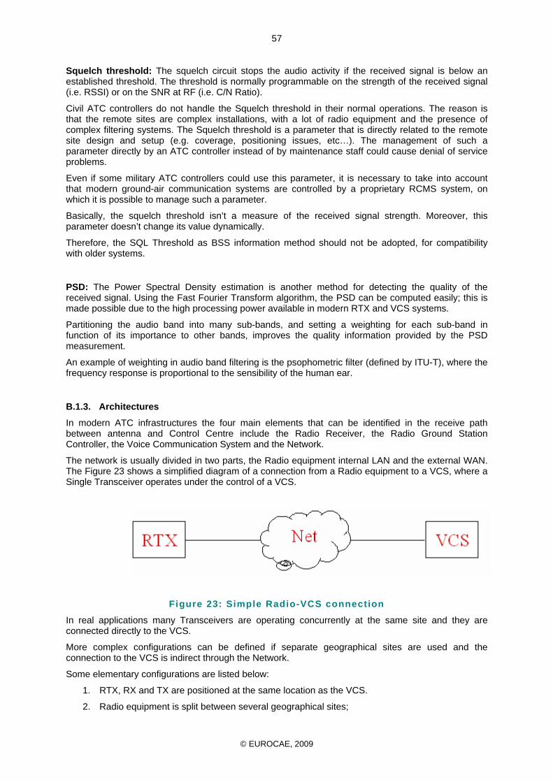
© EUROCAE, 2009
57
Squelch threshold: The squelch circuit stops the audio activity if the received signal is below an established threshold. The threshold is normally programmable on the strength of the received signal (i.e. RSSI) or on the SNR at RF (i.e. C/N Ratio).
Civil ATC controllers do not handle the Squelch threshold in their normal operations. The reason is that the remote sites are complex installations, with a lot of radio equipment and the presence of complex filtering systems. The Squelch threshold is a parameter that is directly related to the remote site design and setup (e.g. coverage, positioning issues, etc…). The management of such a parameter directly by an ATC controller instead of by maintenance staff could cause denial of service problems.
Even if some military ATC controllers could use this parameter, it is necessary to take into account that modern ground-air communication systems are controlled by a proprietary RCMS system, on which it is possible to manage such a parameter.
Basically, the squelch threshold isn’t a measure of the received signal strength. Moreover, this parameter doesn’t change its value dynamically.
Therefore, the SQL Threshold as BSS information method should not be adopted, for compatibility with older systems.
PSD: The Power Spectral Density estimation is another method for detecting the quality of the received signal. Using the Fast Fourier Transform algorithm, the PSD can be computed easily; this is made possible due to the high processing power available in modern RTX and VCS systems.
Partitioning the audio band into many sub-bands, and setting a weighting for each sub-band in function of its importance to other bands, improves the quality information provided by the PSD measurement.
An example of weighting in audio band filtering is the psophometric filter (defined by ITU-T), where the frequency response is proportional to the sensibility of the human ear.
B.1.3. Architectures
In modern ATC infrastructures the four main elements that can be identified in the receive path between antenna and Control Centre include the Radio Receiver, the Radio Ground Station Controller, the Voice Communication System and the Network.
The network is usually divided in two parts, the Radio equipment internal LAN and the external WAN. The Figure 23 shows a simplified diagram of a connection from a Radio equipment to a VCS, where a Single Transceiver operates under the control of a VCS.
Figure 23: Simple Radio-VCS connection
In real applications many Transceivers are operating concurrently at the same site and they are connected directly to the VCS.
More complex configurations can be defined if separate geographical sites are used and the connection to the VCS is indirect through the Network.
Some elementary configurations are listed below:
1. RTX, RX and TX are positioned at the same location as the VCS.
2. Radio equipment is split between several geographical sites;
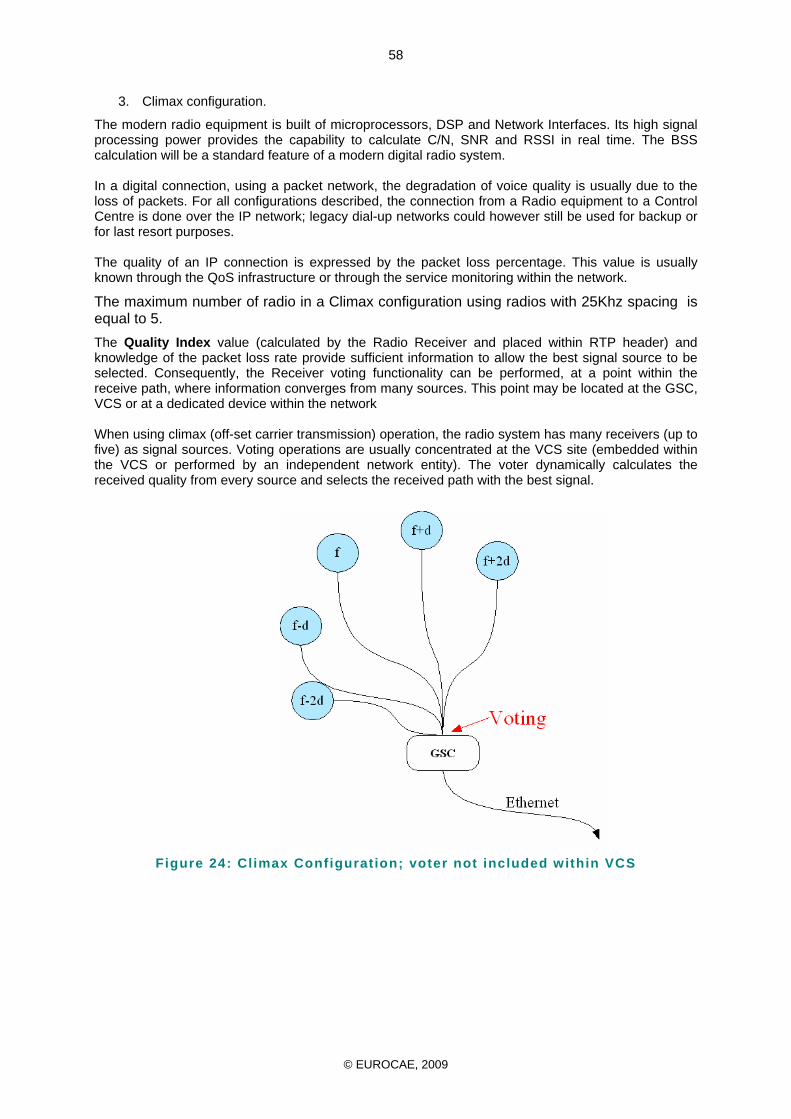
© EUROCAE, 2009
58
3. Climax configuration.
The modern radio equipment is built of microprocessors, DSP and Network Interfaces. Its high signal processing power provides the capability to calculate C/N, SNR and RSSI in real time. The BSS calculation will be a standard feature of a modern digital radio system. In a digital connection, using a packet network, the degradation of voice quality is usually due to the loss of packets. For all configurations described, the connection from a Radio equipment to a Control Centre is done over the IP network; legacy dial-up networks could however still be used for backup or for last resort purposes. The quality of an IP connection is expressed by the packet loss percentage. This value is usually known through the QoS infrastructure or through the service monitoring within the network.
The maximum number of radio in a Climax configuration using radios with 25Khz spacing is equal to 5. The Quality Index value (calculated by the Radio Receiver and placed within RTP header) and knowledge of the packet loss rate provide sufficient information to allow the best signal source to be selected. Consequently, the Receiver voting functionality can be performed, at a point within the receive path, where information converges from many sources. This point may be located at the GSC, VCS or at a dedicated device within the network When using climax (off-set carrier transmission) operation, the radio system has many receivers (up to five) as signal sources. Voting operations are usually concentrated at the VCS site (embedded within the VCS or performed by an independent network entity). The voter dynamically calculates the received quality from every source and selects the received path with the best signal.
Figure 24: Climax Configuration; voter not included within VCS
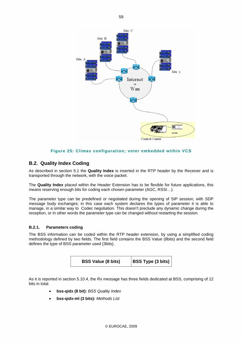
© EUROCAE, 2009
59
Figure 25: Climax configuration; voter embedded within VCS
B.2. Quality Index Coding As described in section 5.1 the Quality Index is inserted in the RTP header by the Receiver and is transported through the network, with the voice packet. The Quality Index placed within the Header Extension has to be flexible for future applications, this means reserving enough bits for coding each chosen parameter (AGC, RSSI…). The parameter type can be predefined or negotiated during the opening of SIP session, with SDP message body exchanges; in this case each system declares the types of parameter it is able to manage, in a similar way to Codec negotiation. This doesn't preclude any dynamic change during the reception, or in other words the parameter type can be changed without restarting the session.
B.2.1. Parameters coding
The BSS information can be coded within the RTP header extension, by using a simplified coding methodology defined by two fields. The first field contains the BSS Value (8bits) and the second field defines the type of BSS parameter used (3bits).
BSS Value (8 bits) BSS Type (3 bits)
As it is reported in section 5.10.4, the Rx message has three fields dedicated at BSS, comprising of 12 bits in total.
• bss-qidx (8 bit): BSS Quality Index
• bss-qidx-ml (3 bits): Methods List
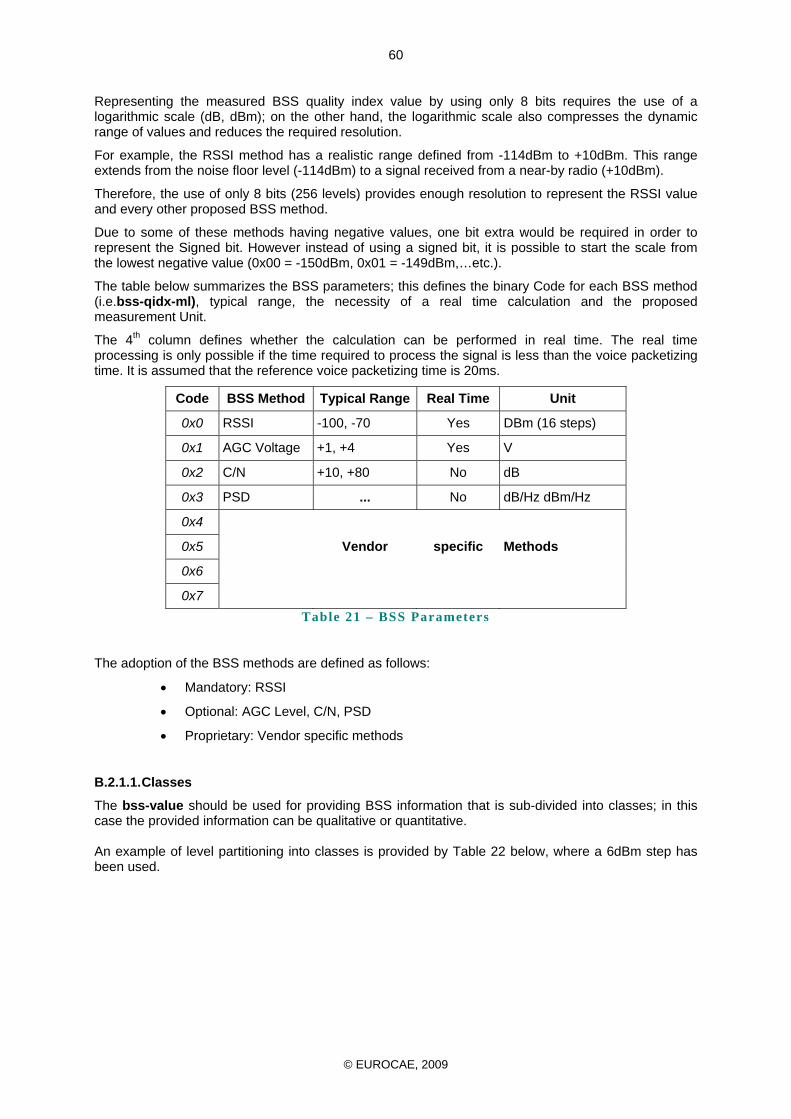
© EUROCAE, 2009
60
Representing the measured BSS quality index value by using only 8 bits requires the use of a logarithmic scale (dB, dBm); on the other hand, the logarithmic scale also compresses the dynamic range of values and reduces the required resolution.
For example, the RSSI method has a realistic range defined from -114dBm to +10dBm. This range extends from the noise floor level (-114dBm) to a signal received from a near-by radio (+10dBm).
Therefore, the use of only 8 bits (256 levels) provides enough resolution to represent the RSSI value and every other proposed BSS method.
Due to some of these methods having negative values, one bit extra would be required in order to represent the Signed bit. However instead of using a signed bit, it is possible to start the scale from the lowest negative value (0x00 = -150dBm, 0x01 = -149dBm,…etc.).
The table below summarizes the BSS parameters; this defines the binary Code for each BSS method (i.e.bss-qidx-ml), typical range, the necessity of a real time calculation and the proposed measurement Unit.
The 4th column defines whether the calculation can be performed in real time. The real time processing is only possible if the time required to process the signal is less than the voice packetizing time. It is assumed that the reference voice packetizing time is 20ms.
Code BSS Method Typical Range Real Time Unit
0x0 RSSI -100, -70 Yes DBm (16 steps)
0x1 AGC Voltage +1, +4 Yes V
0x2 C/N +10, +80 No dB
0x3 PSD ... No dB/Hz dBm/Hz
0x4
0x5 Vendor specific Methods
0x6
0x7 Table 21 – BSS Parameters
The adoption of the BSS methods are defined as follows:
• Mandatory: RSSI
• Optional: AGC Level, C/N, PSD
• Proprietary: Vendor specific methods
B.2.1.1. Classes
The bss-value should be used for providing BSS information that is sub-divided into classes; in this case the provided information can be qualitative or quantitative. An example of level partitioning into classes is provided by Table 22 below, where a 6dBm step has been used.
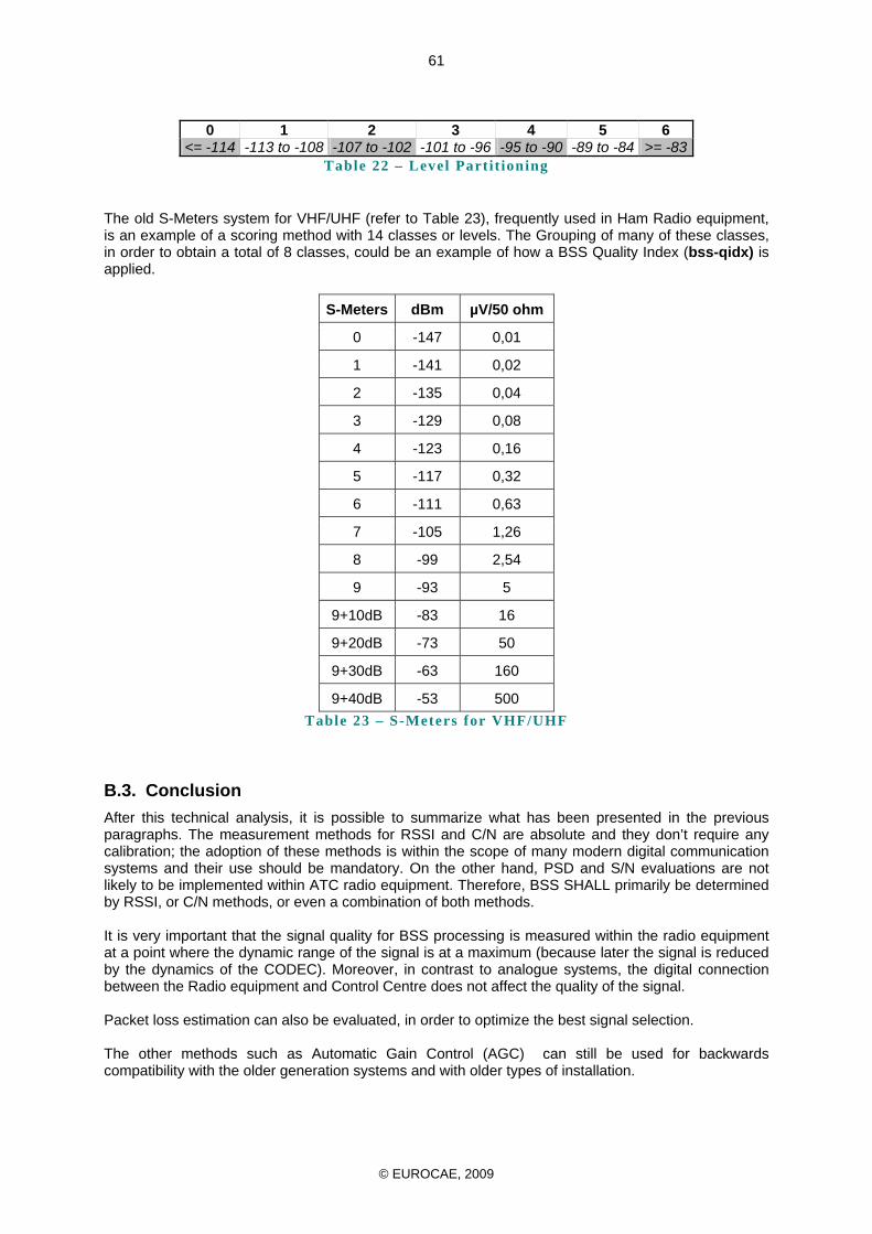
© EUROCAE, 2009
61
0 1 2 3 4 5 6
<= -114 -113 to -108 -107 to -102 -101 to -96 -95 to -90 -89 to -84 >= -83 Table 22 – Level Part it ioning
The old S-Meters system for VHF/UHF (refer to Table 23), frequently used in Ham Radio equipment, is an example of a scoring method with 14 classes or levels. The Grouping of many of these classes, in order to obtain a total of 8 classes, could be an example of how a BSS Quality Index (bss-qidx) is applied.
S-Meters dBm µV/50 ohm
0 -147 0,01
1 -141 0,02
2 -135 0,04
3 -129 0,08
4 -123 0,16
5 -117 0,32
6 -111 0,63
7 -105 1,26
8 -99 2,54
9 -93 5
9+10dB -83 16
9+20dB -73 50
9+30dB -63 160
9+40dB -53 500 Table 23 – S-Meters for VHF/UHF
B.3. Conclusion After this technical analysis, it is possible to summarize what has been presented in the previous paragraphs. The measurement methods for RSSI and C/N are absolute and they don’t require any calibration; the adoption of these methods is within the scope of many modern digital communication systems and their use should be mandatory. On the other hand, PSD and S/N evaluations are not likely to be implemented within ATC radio equipment. Therefore, BSS SHALL primarily be determined by RSSI, or C/N methods, or even a combination of both methods. It is very important that the signal quality for BSS processing is measured within the radio equipment at a point where the dynamic range of the signal is at a maximum (because later the signal is reduced by the dynamics of the CODEC). Moreover, in contrast to analogue systems, the digital connection between the Radio equipment and Control Centre does not affect the quality of the signal. Packet loss estimation can also be evaluated, in order to optimize the best signal selection. The other methods such as Automatic Gain Control (AGC) can still be used for backwards compatibility with the older generation systems and with older types of installation.
© EUROCAE, 2009
62
ANNEX C
CLIMAX CONSIDERATIONS C.1. Purposes Due to environmental or infrastructure constraints, some control sector coverage can not be achieved by only one ground station. In response to such operational constraints it is necessary to use simultaneously several independent ground stations operating with the same frequency. Technically feasible up to five stations (normalized by ICAO annex 10, but usually limited to 4 in practice), this process is called offset-carrier. The offset-carrier implementation is mainly driven by the need to :
- reduce the influence of terrain mask especially for low-level sectors - enable extended range coverage - cope with the unavailability or the lack of suitable location of existing ground stations - provide redundancy for back-up
In Europe, most of the offset-carrier frequencies are operated in two legs (68%) or three legs (28%) configuration.
C.2. Principle In the ground-to-air direction (controller to pilot), the same audio signal is transmitted by all the ground stations involved. To prevent heterodyne interference in the overlapping coverage area of the transmitters, the associated carriers must be offset while staying within the channel width (25kHz). This way, the signal resulting from the recombination of the carriers within the airborne receiver is shifted out of the audio bandwidth. For instance, for two-carrier systems the offsets are set to +/- 5 kHz. In the air to ground direction (pilot to controller) the audio signal received from all or part of these ground stations (depending on the relative location of the aircraft) is sent back to VCSS.
C.3. Issues raised The offset-carrier technique induces some specific interferences that impact the service quality. Thus, it’s use must be restricted to the justified cases only.
C.4. Echo effects Offset-carrier echo, also called “Barrel effect”, occurs when two or more identical audio signals are received and demodulated with relative time delays. This phenomenon can appear either on board or on ground where these incoming signals are combined in the audio circuitry of the airborne receiver or of the VCS respectively. For ground-to-air communications, the echo effects are mainly limited to the overlapping coverage area of the ground transmitters where signal strengths are rather equal (power ratio less than 8dB in practice – no predominance). This area can be more or less complicated due to topography (diffraction) and fluctuate in accordance with propagation change (atmospheric conditions). For air-to-ground communication, this area can be widespread due to AGC action of the ground receivers capable to compensate a large variation of signal levels. In most cases, the relative time delays result from the combination of ground-ground transmission media that are used for linking the ACC to the corresponding remote stations. These time delays can vary to a large extent
- according to the type of medium : leased phone lines, radiolinks, optic fiber links, VSAT links, private copper cable
- or according to new technology as VoIP using Voice packetization process.
C.5. SIGNAL FADING In addition to echo effects, some particular signal fading may happen in the overlapping coverage area. It can be noticed either on board or on ground reception.
© EUROCAE, 2009
63
This phenomenon is mainly due to phase differences between the incoming audio signals that are received via different paths. Moreover, this situation can worsen when carrier-to-noise threshold in implemented in the airborne receiver. Indeed, receiver sensitivity may be deteriorated in the overlapping coverage area with such a particular squelch circuitry,
Contrary to echo effects that result from relative delay of several milliseconds, signal fading in mainly due to both delay differences less than a millisecond (fluctuant part that varies according to aircraft movement) and the “route” used by the audio signal along the ground/ground transmission path .
For ground-to-air communications, when two (or more) carriers are received with similar level by the aircraft, both RF signals are demodulated and the corresponding audio signals are combined on the output line. Hence, the output audio signal to be delivered to pilot headset will be affected both by the relative time delays of the incoming RF signals (echo effects) and the relative phase of the corresponding modulation (signal fading). It will be more or less attenuated, distorted and can be cancelled at specific frequencies. In the worst case (opposite phase – no relative time delay), this output voice signal can be attenuated up to cancellation. For air-to-ground communications, any message received by all or part of the ground stations taking part in climax is sent to VCSS with the same level after AGC compensation. If no selection device is implemented, these incoming signals are simply mixed which entails the same problem as aboard.
C.6. Implementation precautions In the few justified cases where offset-carrier is strictly needed, particular precautions have to be adopted to reduce the impact of the various disturbance effects . IP technology and RTP protocol provide additional information as Time Stamping which can be used to synchronize VCS and radio equipment. Additionally, NTP protocol or local time synchronization can be used by the equipments to provide accurate time stamp which is needed to calculate the time delay between each radio equipment involved in a Climax mode and the VCS.
C.7. air-to-ground communications In the case of air-to-ground communications, all the offset-carrier drawbacks can be easily avoided by introducing Best Signal Selection device . With such a voting process, only one of the incoming audio signals is delivered to controller headset with no echo and no risk of signal fading.
C.8. ground-to-air communications a) Echo effects
If this phenomenon can be countered by introducing Best Signal Selection device on controller reception, time delay differences in ground-ground transmission need to be compensated for controller to pilot communications. This could be adjusted by introducing delay line at VCS or/and Radio equipment.
© EUROCAE, 2009
64
ANNEX D
SECURITY CONSIDERATIONS The first assumption taken in this document was that the underlying IP network that transports the SIP protocol and RTP extender voice packet traffic is a closed network and therefore secure. Although at IP level this infrastructure is by no means public, potential risks will however be considered and for some of them an optional protection mechanism is proposed. A malicious third party who gains access to the IP infrastructure supporting SIP and RTP extender voice traffic may be able to initiate SIP Call to radios or to intercept legitimate packets and attempt to send their own spoofed packets towards one or both Endpoints.
D.1.1. SIP Call control
SIP signalling traffic must be viewed with considerable suspicion, malformed SIP messages should be discarded. If possible originator address SHALL be identified and any unknown originator address SHALL be rejected. As the SIP signalling passes through various servers on route to its destination, the SIP messages acquires information about where the message came from and what devices it passed through. Since global networks are made up of a mesh of service provider networks this information gets passed from network to network. It is therefore important to strip all this information from the signalling prior to it being passed from one network to another. This prevents internal network addresses and client address details from being propagated
D.1.2. Voice packet spoofing
Depending of the processing power of the system hardware that performs the processing of media streams, the extension of the authentication mechanism to voice packets may or may not be effective. If sufficient processing power is available, the authentication code may be added as an extension to every voice packet header as well as the real time signalling extension. If no authentication mechanism is employed and the attacker is unable to suppress the legitimate media flow towards the attacked target, the target will be able to detect that an attack is in progress. The detection is performed by observing a non uniform increment in “sequence number” and “timestamp” fields within the header of the incoming voice packets..
D.1.3. Denial of Service (DoS) attacks
A “Denial of Service” attack consists in a malicious party targeting a very high flow of packets created in such way so as to pass over the regular filters positioned within the network. Depending on the processing power of the system hardware that performs the processing of the media streams, a DoS type of attack may or may not lead to the target entering in a default state. An authentication mechanism is not effective at preventing a DoS attack, moreover it will enhance the destructiveness of such an attack.
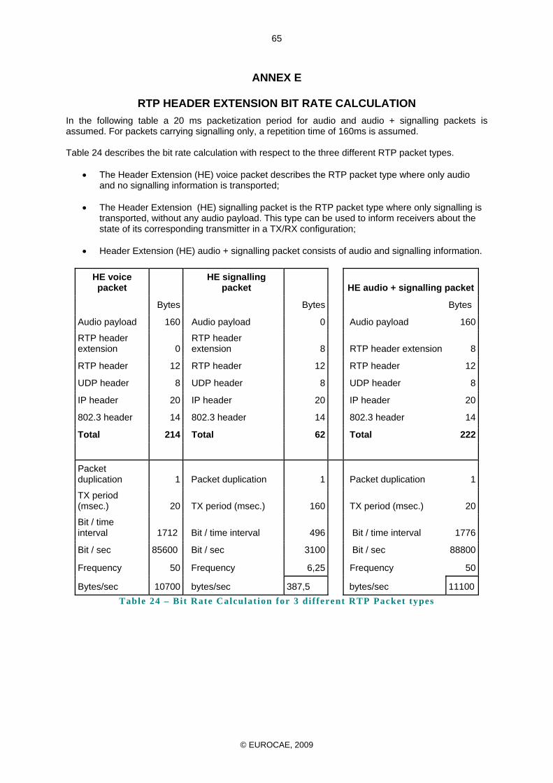
© EUROCAE, 2009
65
ANNEX E
RTP HEADER EXTENSION BIT RATE CALCULATION In the following table a 20 ms packetization period for audio and audio + signalling packets is assumed. For packets carrying signalling only, a repetition time of 160ms is assumed. Table 24 describes the bit rate calculation with respect to the three different RTP packet types.
• The Header Extension (HE) voice packet describes the RTP packet type where only audio and no signalling information is transported;
• The Header Extension (HE) signalling packet is the RTP packet type where only signalling is
transported, without any audio payload. This type can be used to inform receivers about the state of its corresponding transmitter in a TX/RX configuration;
• Header Extension (HE) audio + signalling packet consists of audio and signalling information.
HE voice packet
HE signalling packet HE audio + signalling packet
Bytes Bytes Bytes
Audio payload 160 Audio payload 0 Audio payload 160
RTP header extension 0
RTP header extension 8 RTP header extension 8
RTP header 12 RTP header 12 RTP header 12
UDP header 8 UDP header 8 UDP header 8
IP header 20 IP header 20 IP header 20
802.3 header 14 802.3 header 14 802.3 header 14
Total 214 Total 62 Total 222
Packet duplication 1 Packet duplication 1 Packet duplication 1
TX period (msec.) 20 TX period (msec.) 160 TX period (msec.) 20
Bit / time interval 1712 Bit / time interval 496 Bit / time interval 1776
Bit / sec 85600 Bit / sec 3100 Bit / sec 88800
Frequency 50 Frequency 6,25 Frequency 50
Bytes/sec 10700 bytes/sec 387,5 bytes/sec 11100Table 24 – Bit Rate Calculat ion for 3 different RTP Packet types
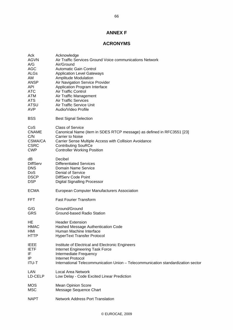
© EUROCAE, 2009
66
ANNEX F
ACRONYMS Ack Acknowledge AGVN Air Traffic Services Ground Voice communications Network A/G Air/Ground AGC Automatic Gain Control ALGs Application Level Gateways AM Amplitude Modulation ANSP Air Navigation Service Provider API Application Program Interface ATC Air Traffic Control ATM Air Traffic Management ATS Air Traffic Services ATSU Air Traffic Service Unit AVP Audio/Video Profile BSS Best Signal Selection CoS Class of Service CNAME Canonical Name (item in SDES RTCP message) as defined in RFC3551 [23] C/N Carrier to Noise CSMA/CA Carrier Sense Multiple Access with Collision Avoidance CSRC Contributing SouRCe CWP Controller Working Position dB Decibel DiffServ Differentiated Services DNS Domain Name Service DoS Denial of Service DSCP DiffServ Code Point DSP Digital Signalling Processor ECMA European Computer Manufacturers Association FFT Fast Fourier Transform G/G Ground/Ground GRS Ground-based Radio Station HE Header Extension HMAC Hashed Message Authentication Code HMI Human Machine Interface HTTP HyperText Transfer Protocol IEEE Institute of Electrical and Electronic Engineers IETF Internet Engineering Task Force IF Intermediate Frequency IP Internet Protocol ITU-T International Telecommunication Union – Telecommunication standardization sector LAN Local Area Network LD-CELP Low Delay - Code Excited Linear Prediction MOS Mean Opinion Score MSC Message Sequence Chart NAPT Network Address Port Translation
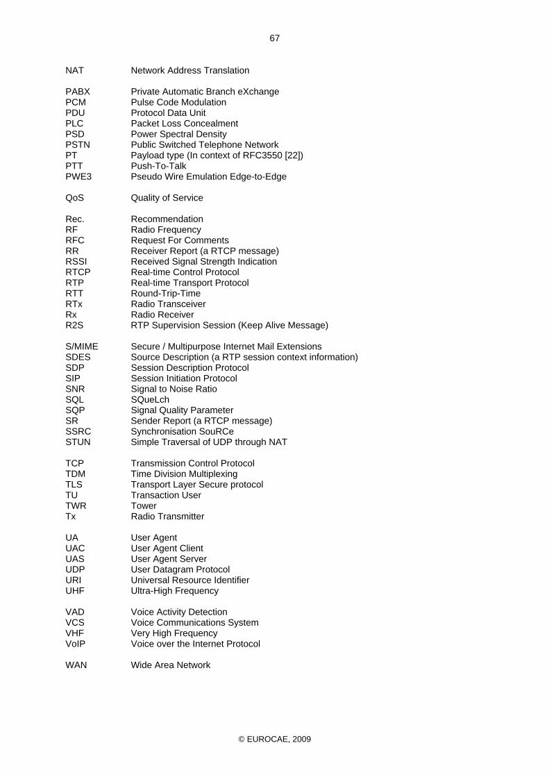
© EUROCAE, 2009
67
NAT Network Address Translation PABX Private Automatic Branch eXchange PCM Pulse Code Modulation PDU Protocol Data Unit PLC Packet Loss Concealment PSD Power Spectral Density PSTN Public Switched Telephone Network PT Payload type (In context of RFC3550 [22]) PTT Push-To-Talk PWE3 Pseudo Wire Emulation Edge-to-Edge QoS Quality of Service Rec. Recommendation RF Radio Frequency RFC Request For Comments RR Receiver Report (a RTCP message) RSSI Received Signal Strength Indication RTCP Real-time Control Protocol RTP Real-time Transport Protocol RTT Round-Trip-Time RTx Radio Transceiver Rx Radio Receiver R2S RTP Supervision Session (Keep Alive Message) S/MIME Secure / Multipurpose Internet Mail Extensions SDES Source Description (a RTP session context information) SDP Session Description Protocol SIP Session Initiation Protocol SNR Signal to Noise Ratio SQL SQueLch SQP Signal Quality Parameter SR Sender Report (a RTCP message) SSRC Synchronisation SouRCe STUN Simple Traversal of UDP through NAT TCP Transmission Control Protocol TDM Time Division Multiplexing TLS Transport Layer Secure protocol TU Transaction User TWR Tower Tx Radio Transmitter UA User Agent UAC User Agent Client UAS User Agent Server UDP User Datagram Protocol URI Universal Resource Identifier UHF Ultra-High Frequency VAD Voice Activity Detection VCS Voice Communications System VHF Very High Frequency VoIP Voice over the Internet Protocol WAN Wide Area Network
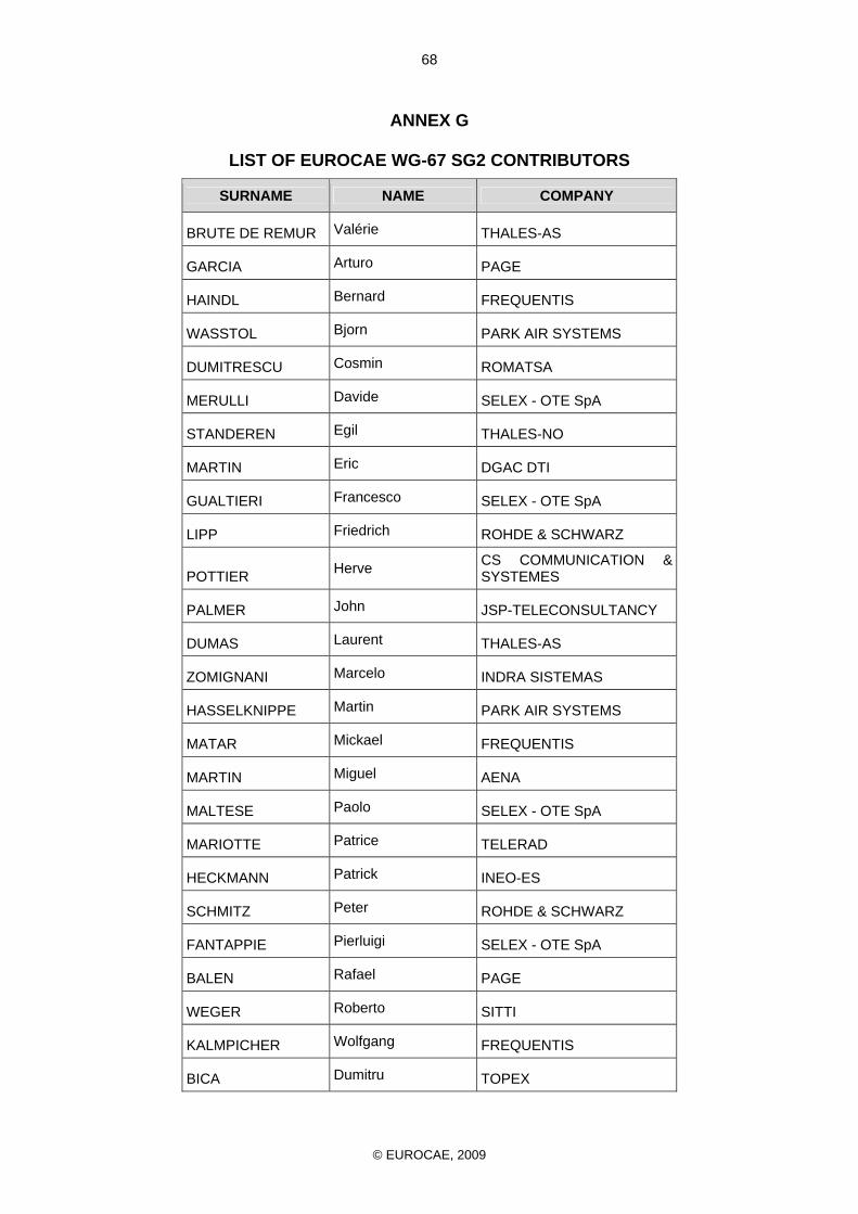
© EUROCAE, 2009
68
ANNEX G
LIST OF EUROCAE WG-67 SG2 CONTRIBUTORS
SURNAME NAME COMPANY
BRUTE DE REMUR Valérie THALES-AS
GARCIA Arturo PAGE
HAINDL Bernard FREQUENTIS
WASSTOL Bjorn PARK AIR SYSTEMS
DUMITRESCU Cosmin ROMATSA
MERULLI Davide SELEX - OTE SpA
STANDEREN Egil THALES-NO
MARTIN Eric DGAC DTI
GUALTIERI Francesco SELEX - OTE SpA
LIPP Friedrich ROHDE & SCHWARZ
POTTIER Herve CS COMMUNICATION & SYSTEMES
PALMER John JSP-TELECONSULTANCY
DUMAS Laurent THALES-AS
ZOMIGNANI Marcelo INDRA SISTEMAS
HASSELKNIPPE Martin PARK AIR SYSTEMS
MATAR Mickael FREQUENTIS
MARTIN Miguel AENA
MALTESE Paolo SELEX - OTE SpA
MARIOTTE Patrice TELERAD
HECKMANN Patrick INEO-ES
SCHMITZ Peter ROHDE & SCHWARZ
FANTAPPIE Pierluigi SELEX - OTE SpA
BALEN Rafael PAGE
WEGER Roberto SITTI
KALMPICHER Wolfgang FREQUENTIS
BICA Dumitru TOPEX


![Jaba Satcom S.A. de C.V. - [ VoIP Satelital ] Telefonia … Satcom S.A. de C.V. [ Ingeniería SatCom ] [ RF Technology ] [ Interoperability ] [ AeroSpace] [Comunicaciones ] [ Telefonía](https://img.pdfslide.us/doc/110x75/5ae2fc697f8b9a7b218c85c1/jaba-satcom-sa-de-cv-voip-satelital-telefonia-satcom-sa-de-cv.jpg)


![An Empirical Analysis of Handoff Performance for …startrinity.com/VoIP/Resources/sip316.pdfSaleh [24] investigated the performance of Mobile IP in the context of an interworking](https://img.pdfslide.us/doc/110x75/5aaee3217f8b9a5d0a8cc507/an-empirical-analysis-of-handoff-performance-for-24-investigated-the-performance.jpg)


![[VoIP] Cisco CallManager Basics (VoIP)](https://img.pdfslide.us/doc/110x75/55cf99c3550346d0339f0d92/voip-cisco-callmanager-basics-voip.jpg)