Embed Size (px)
Citation preview
NTIA Report 83-123
Interoperabi Iityofthe European DefenseCommunications System with Tri-Service
Tactical Communications
J.A. Hoffmeyer
u.s. DEPARTMENT OF COMMERCEMalcom Baldrige, Secretary
Susan G. Stuebing, Acting Assistant Secretaryfor Communications and Information
May 1983


PREFACE
This report is part of a multiphase project to investigate survivability, interoperability, reconstitution, and performance-relatedissues for the Europe~an Defense Communications System (DCS). The project is being conducted by the Institute for Telecommunication Sciencesin Boulder, Colorado, for the U.S. Army Communications Systems P~gency
(CSA) in Ft. Monmouth, New Jersey, on Project Order Number 105-RD.This report, the third report in the series, discusses interopera
bility of the Europea.n portion of the DCS with the TRI-Service TacticalCommunications System (TRI-TAC). The emphasis is on the European Telephone System (ETS) and the Digital European Backbone (DEB) portion ofthe European DCS. Both the digital pipeline and end-to-end levels ofinteroperability are discussed. Recommendations are made for new R&Dprograms to be initia.ted by the CSA.
Other reports in this series are:
"Requirements Analysis for the European DefenseCommunications Systems," by J. A. Hoffmeyer,J. Lemp, Jr., and R. F. Linfield, March 1982,324 pages.
"Integrated Services Digital Networks, Standards,and Related Techno1ogy," NTIA Report 82-103 byD. V. Glen, April 1982, 114 pages. Availablefrom NTIS, Springfield, VA 22161, AccessionNumber PB 83-107573.
The views, opinions, and findings contained in this report arethose of the author and should not be construed as official U.S. ArmyCommunications Systems Agency policy or decisions, unless designatedby other official documentation.
Administration and technical monitoring of this study contractwas performed by Mr. R. Brynildsen of the U.S. Army CommunicationsSystems Agency. Technical management supervision of the program atthe Institute for Telecommunication Sciences was provided by Mr. R. F.Linfield and Dr. P. M. McManamon.
iii


TABLE OF CONTENTS
Page
LIST OF FIGURES
LIST OF TABLES
LIST OF ACRONYMS
ABSTRACT
1. INTRODUCTION
1. 1 Background1.2 Study Objectives and Task Breakdown1.3 Study Assumptions1.4 Report Overview
2. TYPES OF INTEROPERABILITY
vi i
x
xii
1
1
3
5
8
8
10
2.1 Terminology 112.2 Characteristics of Different Types of Interoperability 162.3 Relation to Seven Levels of Interoperability Proposed by LaVean 21
3. REQUIREMENTS
3.1 General Requirements3.2 Digital Pipeline Interoperability Requirements3.3 End-to-End Interoperability Requirements3.4 Mapping of General User Requirements into Technical
Specifications3.5 Specific Requirements
4. EXISTING DCS/TACTICAL INTEROPERABILITY
4.1 AN/TTC-39 and AUTOVON Interface Capability4.2 Requirements Not Satisfied by Existing TRI-TAC/AUTOVON
Interoperabi 1i t,Y
24
27
27
30
3142
42
44
46
5. DIGITAL PIPELINE INTEROPERABILITY ALTERNATIVES AND EVALUATION 48
5.1 Related Work on Pipeline Interoperability5.2 Alternative A: New Intelligent First-Level Multiplexer5.3 Alternative B: Advanced Second-Level Multiplexer
v
50
5969

TABLE OF CONTENTS (cant.)
Page
5.4 Alternative C~ Digital Radio Interface5.5 Evaluation of Alternatives for Digital Pipeline Inter
operability
6. END-TO-END DIGITAL INTEROPERABILITY
74
74
83
6.1 Interoperability Between ETS and TRI-TAC Signaling Systems 856.2 Interoperability Between ETS and TRI-TAC SYSCON Facilities 936.3 Voice Digitization 1006.4 Alternatives for End-to-End Interoperability 101
7. SUMMARY, CONCLUSIONS, AND RECOMMENDATIONS 102
7.1 Recommended Tasks for Digital Pipeline Interoperability 1037.2 Recommended Tasks for End-to-End Interoperability 109
8. REFERENCES
APPENDIX A: EUROPEAN DCS AND TRI-TAC ARCHITECTURE AND EQUIPMENTCHARACTERISTICS
APPENDIX 8: VOICE DIGITIZATION COMPARISON
APPENDIX C: LINE CODES
vi
115
119
153
160

LIST OF FIGURES
Page
Figure 1.
Figure 2.
Figure 3.
Figure 4.
Figure 5.
DCS/TRI-TAC interoperability as it relates to communicationsservices survivability and extettsion of network coverage.
Interrelationship of the tasks being performed.
Interoperabi 1i ty i s·sue broken intosubtasks.
Examples of different types of;:nteroperabi 1; ty.
Example of need for DCS/TRI-TAC/DCSdigital pipelineinteroperability.
2
6
7
12
14
Figure 6.
Figure 7.
Figure 8.
Figure 9.
Figure 10.
Figure 11 .
Figure 12.
Figure 13.
Figure 14.
Figure 15.
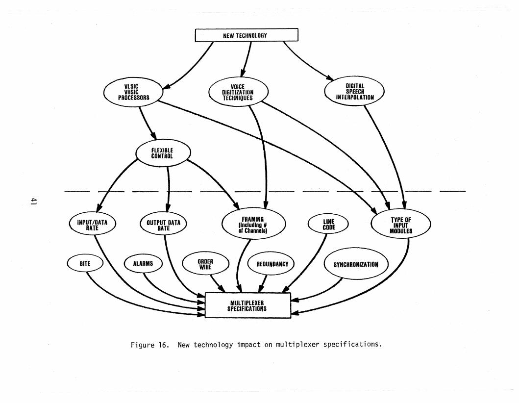
Figure 16.
Figure 17.
Figure 18.
Figure 19.
Figure 20.
Example of need for TRI-TAC/DCS/TRI-TAC digital pipe~ine
interoperability. 15
Tree diagram on interoperability including unified signalstructure. 28
Factors that have an impact on radio and multiplexerspecifications. 32
User requirements impact on radio specifications. 34
Network operator requirements impact on radio specifications. 35
New technology impact on radio specifications. 36
Regulatory requirements impact on radio specifications. 37
Operating environment impact on radio specifications. 38
User requirements impact on multiplexer specifications. 39
Network operator requirements impact on multiplexerspecifications. 40
New technology impact on multiplexer specifications. 41
Possible interface points for digital pipeline interopera-bility. 49
DCS/tactic~l interface facility. 51
Digital access and cross-connect system (DACS) concept. 53
Digital channel efficiency model (DCEM) operational modes. 54
vii

LIST OF FIGURES (cont.)
Page
Figure 21. DCEM frame format.
Figure 22. DCS/TRI-TAC interoperability proposed by CSC.
Figure 23. Alternative A: intelligent, first-level multiplexer.
58
60
61
Figure 24. First-level intelligent mUltiplexer operational examples. 63
Figure 25. First-level intelligent multiplexer functional blockdiagram (multiplexer portion only). 67
Figure 26. Alternative B: advanced second-level multiplexer. 70
Figure 27. Advanced second-level multiplexer concept. 73
Figure 28. Alternative C: modified DRAMA radio. 75
Figure 29. Typical DEB nodes. 81
Figure 30. Typical TRI-TAC switching configuration for a call. 87
Figure 31. Typical TRI-TAC signaling generated by call setup/teardown. 88
Figure 32. Comparison of TRI-TAC CCS and CCITT #7 formats.
Figure 33. DCS system control (SYSCON) structure.
Figure 34. System control functions.
Figure 35. TCCF functional flows.
94
95
97
98
Figure 36. Translation of general requirements as stated by DCA intorecommendations for new R&D programs at CSA. 104
Figure 37. Digital pipeline interoperabi1ity alternatives. 105
Figure 38. Recommended tasks for intelligent first level multiplexerdevelopment. 106
Figure 39. Recommended tasks for end-to-end interoperability. 110
Figure A-l. ETS architecture. 120
Figure A-2. Typical ETS switch and DCS transmission node. 121
Figure A-3. Typical DEB nodes using DRAMA equipment. 122
viii

LIST OF FIGURES (cont.)
Page
Figure A-4. DRAMA multiplexers and radio. 123
Figure A-5. AN/FCC-99 block diagram. 124
Figure A-6. Evolution of Army tactical communications to the INTACSobjective system. 132
Figure A-7. Typical TRI-TAC equipment interconnects. 133
Figure A-B. TRI-TAC multiplexer hierarchy. 137
Figure A-g. TRI-TAC multiplexer signal format organization - fourminor frames (used in RLGM). 138
Figure A-10. TRI-TAC ,multiplexer signal format organization - eightminor frames. 139
Figure A-ll. TRI-TAC AN/TRC-170 radio terminal set. 144
Figure A~12. AN/TTC-39 nodal circuit ~witch interconnectivity. 147
Figure A-13. Nodal message switch (AN/TYC-39) interconnectivity. 148
Figure B-1. Speech quality versus codec complexity for several bitrates. 155
Figure C-l. Comparison of commonly used line codes. 161
Figure C-2. Comparison of conditioned diphase (COP) encoding withdiphase (Manchester) coding. 162
ix
LIST OF TABLES
Page
Table 1. Problem Areas Selected for Detailed Analysis 4
Table 2. Constraints 9
Table 3. Terminology Describing Different Types of Interoperability 17
Table 4. Parameters Affected by Different Types of Interoperabi1ity 18
Table 5. Characteristics of Digital Transmission Facilities andDigital Voice Networks in Europe 20
Table 6. Relationship to the Seven Levels of InteroperabilityIntroduced by LaVean 23
Table 7. Basic User Requirements for DCS/TRI-TAC Interoperability 26
Table 8. DEB/TRI-TAC Interoperability Requirements 43
111
Table 10.
Table 11 .
Table 12.
Table 13.
Table 14.
Table 15.
Table 16.
Table 9. Alternative A - Example Data Rates and Corresponding Numberof Channels for Intelligent First Level Multiplexer 64
Alternative B - Example Data Rates and Corresponding Numberof Channels for New Second-Level Multiplexer 71
Alternative C - Example Data Rates for Modified DRAMARadio 76
Approaches to Digital Pipeline DCS/TRI-TAC Interoperability 77
TRI-TAC Trunk Signaling Messages 89
Equivalency Between TRI-TAC and CCITT No.7 Signaling Messages 91
First Level Intelligent Multiplexer Development Task 1:Operational Mode Definition 107
First Level Intelligent Multiplexer Development Task 2:Specifications Development (Detailed Design Study) 108
Table 17. End-to-End Interoperabi1ity Task 2: Detailed Study ofSYSCON Interoperability
Table 18. End-to-End Interoperability Task 3: Detailed Study ofCommon Channel Signaling Interoperability 112
Table 19. End-to-En~ Interoperability Tas 4: Detailed Study ofOther Major Parameters of ETS a d TRI-TAC 113
x

LIST OF TABLES (cant.)
Page
Table' 20. End-to-End Interoperability Task 5: Survey of ExistingSwitch Technology 114
Table A-1. Characteristics of DRAMA Radio 125
Table A-2. DRAMA Radio Versions 126
Table A-3. FCC-98 Configuration Options 127
Table A-4. AN/FCC-99 Second Level ~1u1tiplexer I/O Rates 128
TableA-5. FCC-99 Port Data Rate Combinations 129
Table A-6. Features of KN-101 Switch 131
Table A-7. Equipment Being Developed for TRI-TAC 134
Table A-8. Characteristics of TRI-TAC Multiplexers 140
Table A-9. Remote Multiplexer Combiner (RMC) 141
Table A-10. DGM Equipment Usage
Table A-ll. Digital Transmission Group Bit Rates (Nominal)
142
143
Table A-12. AN/GRC-144 Radio Characteristics 145
Table A-13. AN/TRC-170 Radio Characteristics 146
Table A-14. AN/TTC-39 Hybrid Circuit Switch Interface Capabilities 149
Table B-1. Evaluation Factors for Voice Digitization Algorithms
Table B-2. Comparison of Voice Digitization Techniques
Table B-3. Conclusions of Speech Coding
xi
154
157
159
ASSACCACKAIDADCCPADPCMATACSAUTODINAUTOSEVOCOMAUTOVONBERBITEBPCAlCCITTCCNCCSCOPCEPT
CESECINCEURCNCECOMSTRESSCRFCSACSCCSCECSPECVSDD/ADACSDCA
LIST OF ACRONYMS
- aggregate bit stream- Army Communications Command- acknowledge- analog-to-digital- Advanced Data Communications Control Procedure- adaptive differential pulse code modulation- Army Tactical Communication System- Automatic Digital Network- Automatic Secure Voice Network- Automatic Voice Network- bit error rate- built-in test equipment- bipolar- channel assignment information- International Telegraph and Telephone Consultative Committee- Control Communications Network- common channel signaling- conditioned diphase- European Conference of Postal and Telecommunications
Administrations- Communications Equipment Support Element- Commander-in-Chief, Europe- Communications Nodal Control Element- Communications Under Stress- Channel Reassignment Facility- Communications Systems Agency - U.S. Army- Computer Sciences Corporation- Communications System Control Element- Communications System Planning Element- continuous variable slope delta- digital-to-analog- Digital Access and Cross-Connect System- Defense Communications Agency
xii
DCAOCDCECDeEMDCSDDRDEBDEMUXDPDPASDRAMADSIDSNDTIFDTMFETSGMHDB3HSCDMICDIOCSIRAOINTACSITSJCSJMTSSKP
LBLCCLGMLOSLSCDMLSTDM
LIST OF ACRONYMS (cont.)
- DCA Operations Center- Defense Communications Engineering Center- Digital Channel Effic1en~y Model- Defense Communications System- Digroup Data Reduction- Digital European Backbone- demultiplexer- dipul'se- Digital Patch Access System- Digital Radio and Multiplexer Acquisition- digital speech interpolation- Defense Switched Network- DeS/Tactical Interface Facility- dual tone multifrequency- European Telephone System- Group Modem- high density binary - 3- High Speed Cable Driver Modem- Interface Control Document- Integrated Defense Communications System- internal research and development- Integrated Tactical Communication System- Institute for Telecommunication Sciences- Joint Chiefs of Staff- Joint Multichannel Trunking and Switching System- key pul se
line busy- life cycle cost- Loop Group Multiplexer- line-of-sight- Low Speed Cable Driver Modem- Low Speed Time Division Multiplexer
xiii
MBS
MEPMFMFCMGM
MIL-DEPMLPPMSCMUXNBNCFNICSNRZO&MPBXPCMPROMPTTQAM
QPSKRADCRAMRCOCRDT&E
RECONRFRMCROMSCBSSCFSR\~BR
SSB-AM
LIST OF ACRONYMS (cont.)
- mission bit stream
- Management Engineering Plan
- multifrequency- Military Function Controller- Master Group Multiplexer- Military Department- multilevel precedence and preemption- Maintenance Service Center
- multiplexer- narrowband- Network Control Facility- NATO Integrated Communication System
- non-return-zero- operation and maintenance- private branch exchange- pulse code modulation- programmable read-only memory- Postal, Telephone and Telegraph- quadrature-amplitude modulation- quadrature phase shift keying- Rome Air Development Center- random access memory- Regional Control Operations Center- Research, Development, Test, and Engineering
- reconstitution- radio frequency- Remote Multiplexer Combiner
read-only memory- service channel bit stream- Sector Control Facility- Short RangeWideband Radio- single-sideband amplitude modulation
xiv
SYSCONT8
TCCFTCFTOMTGMTIFTRAMCONTRI-TACVFVHSICVLSICWWDSAWWOLS
LIST OF ACRONYMS (cont.)
- system control- trunk busy- Tactical Communications Control Facility- Technical Control Facility- time division multiplexing- Trunk Group Multiplexer- Tactical Interface Facility- Transmission Monitor and Control- TRI-Service Tactical Communications System- Voice Frequency- very high scale integrated circuits- very large scale integrated circuits- Worldwide Digital Systems Architecture- Worldwide On-Line System
xv


INTEROPERABILITY OF THE EUROPEA~DEFENSE COMMUNICATIONSSYSTEM ~JITH TRI-SERVICE TACTICAL COMMUNICATIONS
lJ. A. Hoffmeyer*
This report discusses the different types of interoperability requirements, summarizes several relatedres,earch and development projects,and presents a1terna ti ves for achi evi ng i nte/roperabi 1i ty between theDefense Communications System and the TRI-Se,rvice Tactical CommunicationsSystem. These alternatives are evaluated,and a preferred alternative isrecommended. The report concludes with.brief tasking statements whichare recommended to the U.S. Army Communications Systems Agency as thenext steps in pursuing a research and development program for developinginteroperability of the two systems at both the transmission subsystemlevel and at the end-to-end subscriber level. For transmission subsysteminteroperability, emphasis is placed on the Digital European Backbone andDigital Radio and Multiplexer Acquisition portions of the European DCS.
Key words: DCS; DEB; Digital European Backbone; digital radio; DRAMA;interoperability; multiplexer acquisition; TRI-TAC
1. INTRODUCTIONCommunications netwoY'k survivability is currently a subject of considerable
interest throughout the defense communications community. One reason for thisinterest is that the nodes and links of the European Defense CommunicationsSystem (DCS) have been shown to be quite vulnerable to sabotage, conventionalwarfare, and jamming in addition to the widely recognized vulnerabili'ty tonuclear attack. The emphasis in this report ison the survivability of communication services, especially to critical users, rather than on the survivabilityof communication facilities. A well-designed network may continue to provide
t
essential communications services despite damage to lportions of the network.There are several approaches to enhancing the survivability of communication
services. This is illustrated in Figure 1. As a starting point, one should havea robust network design with dual or multiple homing between nodes. Secondly,site hardening and the provision of physical security should be added as appropriate. Thirdly, provisions should be made for restoring communications serviceafter a disruption caused by network damage through the use of prepositioned
*The author is with the Institute for Telecommunication Sciences, National Telecommunications and Infornlation Administration, U./S. Department of Commerce,Boulder, CO 80303.

i -
ISSUE
SURVIVABILITY OF CONNUNICATION SERVICES
ISSUE
GEOGRAPHICAL COVERAGE
ROBUSTNETWORKDESIGN
SITEHARDENING
~
POST-ATTACKSERVICE
RESTORATION
•Des
INTEROPERABlllTYWITH OTHERNETWORKS
Ir
USE OF THE DCSTO INTERCONNECT
TACTICALOPERATIONAL AREAS
•EXTENSIONOi THE DCS
USING TACTICALASSETS
_-----....1-..... . , •
f")
DCSRECONSTITUTION
PACKAGES
RECONSTITUTIONOF THE DCS USINGTACTICAL ASSETS
~ • * •DCS/TRI-TAC INTEROPERA81LITY REQUIREMENTS
Figure 1. DCS/TRI-TAC interoperabilityas it relates to communications servicessurvivability and extension of network coverage.
reconstitution packages. As a fourth step, the network should be made to beinteroperable with other networks thereby providing more diversity in the pathsbetween any pair of users. The focus of the paper will be on the interoperability approach including the use of tactical assets to re-establish service
for damaged DCS nodes and links.11There is another~motivating factor for~he investigation of the interopera-
bility of the DCS with the TRI-Service Tactical Communications Systern. The geographical coverage of the DCS could be extended using TRI-TAC facilities or,conversely, the DCScould be used to extend TRI-TAC coverage. For example, onecan envision two or more ~)eographica lly separated tactical operational areasinterconnected using the DCS as the backbone transmission facilities between thetactical areas.
The specific problem addressed in this report is that of achieving interoperability between the Digital European Backbone (DEB) and the European Telephone System (ETS) on the DCS side of the interface and on TRI-TAC on the tactical side. A more general treatment of theinteroperability problem might includeATACS (Army Tactical Communication System), NICS (NATO Integrated CommunicationSystem), AUTOVON, etc. However, it is expected that the ETS, DEB, and TRI-TACwill be the predominate U.S. communication systems in Europe startinH in thelate 1980's. Therefore this report will consider only these systems.
1. 1 BackgroundThis report is part of a multiphase project to investigate U.S. military
conmunications systems requirernents in the European Theater. The oVE~rall purposeof this study is to assist the U.S. Army Communications Systems Agency (CSA) inidentifying R&D (research and development) programs needed to achieve the goal ofa highly survivable, and high performance DCS in Europe that is interoperablewith other networks. The intent is to emphasize those portions of the survivability, interoperability, reconstitution, and performance issues that influencethose hardware and software items that are the responsibility of CSA. Much ofthis study effort is therefore oriented around multiplexer, radio, and modemrequirements. Some discussion of switch requirements is also included.
Previous phases of this study have identified numerous issues in the Euro-
pean DCS. Of the long list of issues that have been identified, several have been
chosen for a detailed analysis. These issues are listed in Table 1. The issuesare divided into the near-term (1984-1990) and far-term (1988-2000) categories.
3

Table 1. Problem Areas Selected for Detailed Analysis
Near-Term Issues Far-Term Issues
-+:::a
1. DCSjTRI-TAC Interoperability
2. Reconstitution
3. LOS Multipath Fading
1. Far Term Architectural Issues
- Application of ISDN Technology to theDeS
- Evaluation of WWDSA and Identificationof R&D Programs Needed to Realize theWWDSA Goal Architecture
4. Vulnerability of High Efficiency Modemsto Jamming - Protocols and Standards
2. Survivability Modeling

The far-term issues are those that may require major new development programs oreven new architectural concepts such as the Worldwide Digital ;Systems Architecture(W~~DSA). The near-term issues are those that are seen to be solvable, at leastin part, in the 1980·s.
The subject of this report is the DCS/TRI-TAC interoperability 'issue. Separate reports are planned that address the remainder of the issues listed in Table 1.
Figure 2 depicts the interrelationship of tasks being performed. The TRITAC/DCS interoperability issue is partially related to the reconstitution issuebecause TRI-TAC assets could, if interoperable, be utilized to reconstitute damaged or destroyed portions of the DCS.
There are three different levels of DCS/TRI-TACinteroperability that areclearly identifiable and these are shown in Figure 2. These levels are the digital pipeline level, the end-to-end interoperability level, and the highest levelwhere the same system' i sused to meet therequi rem~nts for both tact"i ca1 andstrategic communications. The first two levels are addressed in this report.The II same system ll level can be achieved only in the far, far term (post 2000),and will probably be influenced by the evol~tion to the WWDSA architecture.Other authors (LaVean, 1980) have identified some additional lintermediate levels
U~
of interoperability for a total of seven levels. This will b:~ discussed morei .~ ::
fully in Section 2. "One purpose in presenting Figure 2 is to indicate completed tasks. Note
that the investigation of the DCS/TRI-TAC interoperability issue has as its output recommendations for R&D programs for radio, multiplexer, or switch development or modification. These recommendations are found in Section 7 after discussing various alternatives in Sections 5 and 6.
1.2 Study Objectives and Task BreakdownThe objective of the DCS/TRI-TAC interoperability task is to identify alter
natives for achieving different levels of interoperability, to evaluate thesedifferent alternatives,and to make recommendations to CSA for any new hardwareor software development or modifications. The task is broken down into severalsubtasks as is illustrated in Figure 3. The two major levels of interoperabilitytreated in this report, are the transparent digital pipeline level and the en'dto-end subscriber interoperability level. The latter is more complex than theformer because it involves such parameters as numbering plans, signaling, androuting control, while the former is merely a sharing of transmission resources.
5

Q)
I I·Ongoln.T....
~aC~TaoIc
<=> "Output
Figure 2.
Multiplexef, Radio orlSwitch Modification
or Development
Interrelationship of the tasks being performed.

ISSUEOCS/TRI-TAC INTEROPERABILITY
DEFINE REQUIREMENTS FORSection 3.21 PARTIAL INTEROPERA BILITY
(TRANSPARENT DIGITAL PIPELINE)DEFINE REQUIREMENTS FOR "'I S · '2 '2.
END-TO-END INTEROPEJ1ABILITY .echon ~.J
Appendix A-2ASSESS CHARACTERISTICS
Of ETS l DEB
Section 1.3
ASSESS .,CHAR ACTERISTICSOF TR I-lACAppendix A-I
SectionS
IDENTIFY POSS tBLEIHTE RFACE POINTS
EVALUATE AND COMPAREALTERNATIVES
SELECTEVALUATIONCRITERIA-...---
"
Section' 5
EXISTINGSection 411NTEROPERABIli lY
..........
DEVELOP SPECIFICATIONS FORMOST LIKELY CA NDIDATE(MULTIPLEXERS OR RADIO)
RECOMMENDATIONS FORRlD PROGRAM FOR THE
FAR-TERM
Sec tion 7RECOMMENDATIONS FOR
FUTURE RlO TASKS
Figure 3. Interoperability issue broken into subtasks.

The end-to-end level of interoperability is thought to be a far-term problem,while the digital pipeline level is viewed as a near-term problem. The abilityto make the transition from a near-term limited interoperability solution to an
end-to-end or subscriber-to-subscriber level of interoperability also must beaddressed. Figure 3 indicates the section number of this report in which eachof the subtasks is discussed.
1.3 Study AssumptionsTable 2 lists several assumptions that have been made. The first assumption
is that a requirement exists for a DCS/TRI-TAC interface at some level above theanalog voice frequency (VF) level. Since the requirements for interoperabilityor, indeed, its very definition, are not generally agreed upon it is necessaryto state at the start that the view taken herein is that there is a requirementfor a higher level of interoperability other than at the VF level. Requirementswhich support this assumption are discussed in Section 3.
Because the traffic levels for the gateways between the DCS and TRI-TAC networks have not been fully defined, it is necessary that the interface points beassumed to have sufficient flexibility to handle a growth in traffic. Documentssuch as the INTACS System Architecture (Pound, 1979) identify the need for interfaces between tactical communications systems and the DCS, but do not discuss thelevel of traffic through the interface.
A further assumption made is that some equipment development can be accomplished in the near term, but that major new systems {such as switches} can bedeveloped only to satisfy requirements in the far term (1988 and beyond). It isassumed that for the near term (1984-1988) that the DRAMA (Digital Radio andMultiplexer Acquisition) equipment will be fielded approximately on schedule,that the Digital European Backbone (DEB) will be implemented according to theplanned schedule, and that the TRI-TACfamily of digital multiplexers and radioswill be available. These equipments are all assumed to be the fundamental elements of the DCS and TRI-TAC during the mid- to late-1980·s. Interface alternatives will be developed in later sections of this report that will be orientedaround these equipments.
1.4 Report OverviewSection 2 of this document contains a discussion of different types and
levels of interoperability. Because the word ~nteroperability means different
8

\D
Table 2. Constraints
- a requirement exists for a DCS/TRI-TAC interface at some level abovethe analog VF level of interoperability
== the traffic has no impact on the features of the network components;the DCS and the TRI-TAC networks and their major components as wellas the gateways between the networks can be designed with sufficientmodularity that traffic levels need not be considered in this study
- some equipment development can be accomplished in>thenear-term(e.g., an intelligent 'multiplexer). The development of new switchesor switch modification (Which might be required ,for~he fullinteroperability case) could be accomplished only in the far-term
- DCS and TRI-TAC multiplexers and radios will be fielded approximatelyon schedule
things to different people, it is important to define how the word is used inthis report. Section 2 also contains a brief discussion of the characteristicsof various types of interoperability and relates the types of interoperabilitydiscussed in this report to the seven levels of interoperability that have beenidentified by LaVean (1980).
Section 3 is a discussion of the requirements for the digital pipeline andend-to-end levels of interoperability. Section 3 concludes with a discussionof how communications network user1s and operator1s general requirements may bemapped into specifications for radios and multiplexers.
Section 4 is a brief description of the existing capability for DCS/TRI-TACinteroperation at the VF level. Problems and deficiencies with this type ofinteroperability are identified.
Sections 5 and 6 contain discussions of alternatives for achieving interoperability at the digital pipeline and end-to-end levels, respectively.
Section 7 contains recommendations for specific R&D tasks that should beconducted by CSA as the next step toward achieving full interoperability betweenthe DCS and TRI-TAC.
Appendix A provides a summary of the major characteristics of the EuropeanTelephone System (ETS), the Digital European Backbone (DEB), Digital Radio andMultiplexer Acquisition (DRAMA) equipment, and TRI-TAC architecture and equipment. Appendix B provides a brief comparison of the performance of differentvoice digitization techniques. Appendix C compares different line codes.
2. TYPES OF INTEROPERABILITYThe Joint Chiefs of Staff PUB 1 provides the following definition of inter
operability:
"Interoperability - the ability of systems, units, or forcesto provide services to and accept services from other systems,units, or forces and to use the services so exchanged to enablethem to operate effectively together. II
Unfortunately, this general definition of interoperability does not address thedegree, or level, of interoperability between systems. Nor does it indicatewhat is meant by "serv ices." For communications network interoperability, oneneeds to define whether "services" means end-to-end user services, transmissionservices, or some other level of service. Furthermore, the interoperability oftwo communications networks may consist of any of the following:
10

1) . manually assisted interconnects at the analog VF level
2) partially automated interconnects that are achieved throughthe use of inteY'face boxes for signal format conversion
3) a fully automatic interconnect.
The word interoperability means different things to different people. Awhite paper on interoperability prepared by the Army Communications Command (ACC,1980) states that while interoperational needs are conceptually outlined in general terms, the specific degree, scope, and level of interoperability are notusually defined. There is no unanimity on the degree of interoperation that isrequired. Consequently, major systems eyolve separately resulting in systemslacking common standards and having inherent incompatibilities between the hierarchies of the major systems. The ACC white paper further states that:
IILacking are definitive and commonly understood and accepteddefinitions/standards forin-teroperability between systems, deflinitions of military networks architectures for major systems ... andsufficient interoperation requirements. 1I
In order to clarify the meaning of the word interoperability as it is usedin this report, the following subsections include a discussion of some interoperability-related terminology that is frequently encountered, a discussion of thecharacteristics of different types of interoperability, and a discussion of thetypes of interoperability addressed in this report as they relate to the sevenlevel interoperability hierarchy defined by DCA.
2.1 TerminologyTwo levels of interoperabilityare discussed in this report. The first is
the digital pipeline (or limited) interoperability level, while the second isthe end-to-end (or full) if nteroperabi 1i ty level. Figure 4 introduces these concepts. The digital pipeli:ne concept is one in which the resources of one network are used to satisfy partially the transmission requirements of a second,while the end-to-end concept implies that a subscriber in one network can communicate directly, and automatically, with a subscriber in another network.These concepts are elaborated on in the following paragraphs.
Under the digital pipeline concept a subscriber in one network (say DCS)cannot dial directly a subscriber in a second network (say TRI-TAC), or viceversa. We restrict the pipeline concept to be a digital pipeline, because the
11

(0) DIGITAL PIPELINE (Limited Interoperability)
EXTENSION OFa·l DeS COVERAGE
AND DCSRECONSTITUTION
a-2 EXTENSiON OFTRI--TAC COVERAGE
DCSSUBSCRIBER
TRI·TACSUBSCRIBER
Tnl-TACTRANSMISSION
FACILITIES
DCSTRANSMISSION
FACILITIES
DCSSUBSCRIBER
TRI-TACSUBSCRIBER
N
(b) END-TO-END (Full Interoperobility)
~fi~seRIBER rl DeS I IrBI-rAC h
Figure 4. Examples of different types of interoperability.
TRI-TACSUBSCRIBER

transmission facilities of both the ETS andTRI-TAC will be changing toward anall digital network. In order to achieve the digital pipeline level of interoperability~ there must be compatible digital bit rates between the two networks~
the line codes (see Appendix C for adiscription of line codes) must be compatible~ and synchronization rnust be achi,eved. However~ there is no nee~ for compatibility between numbering plans~ signaling techniques~ routing control~ etc.The pipeline is transparent to the type of information being carried. The pipeline can carry any bit stlream as long as the data rates and line codes are compatible.
As depicted in Figure 4 there are two cases for the digital pip~~line levelof interoperability. The first ;s the use of TRI-TAC transmission facilities toprovide connectivity between two segments of the DCS. This case may be thoughtof as the IIrecons ti tuti on caselO where tacti ca1 facil i ti es are uti 1i zed to res torecommunication service between two or more disjoint portions of the DeS that havebeen disconnected due to damage to the network. The second case is the use ofDeS transmission facilities to serve as the backbone between two geo~}raphically
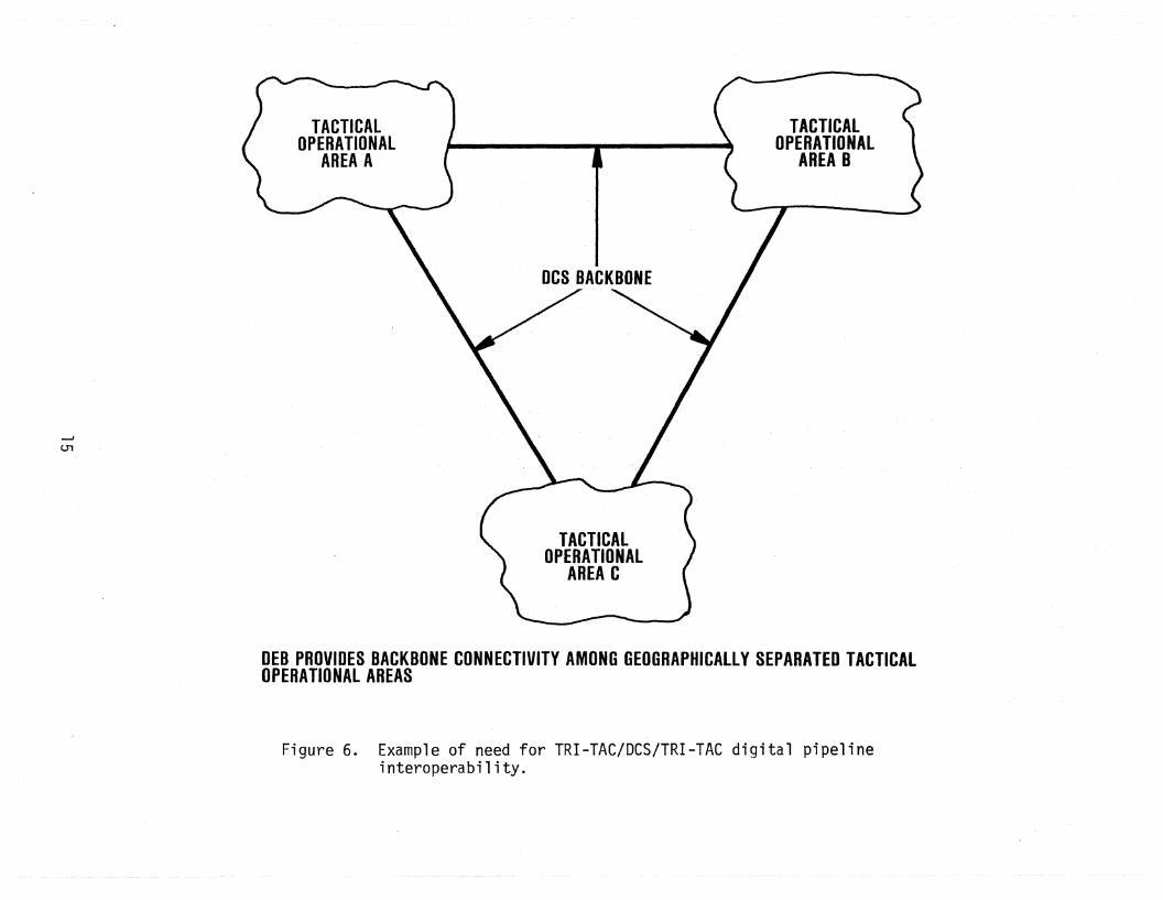
separated tactical operational areas. This would provide an extension of TRITAC coverage.
Figures 5 and 6 illustrate the need for each of the two cases of the digitalpipeline level of interoperability. More will be said in Section 3 about requirements as they have been stated by DCA. Here, we shall limit out~selves toa brief discussion of how the digital pipeline might be applied in two theoretica1 scena ri os .
Figure 5 illustrates a hypothetical use of tactical assets to restore connectivity in a damaged portion of the Digital European Backbone. A typical portion of the DEB is illusty'ated in Figure 5a that is typical of connectivity foundthroughout DEB. In our hypothetical example we assume that the back-to-back repeater site at Hohenpeissen has been eliminated either by hostile action, perhapssabotage, or by some natuY'al disaster. Service between Munich and Reese Augsburgcould be restored using tactical assets as long as the digital pipeline level ofinteroperability is provided between DEB and TRI-TAC equipments. Note that thereis no DCS or TRI-TAC switch involved in this interopera,bility requirement. Whilepre-positioned DCS reconstitution packages could also be used to re-establish
connectivity between disjoint portions of the DCS, other options should also beconsidered such as the use of tactical assets.
13

TO HEIDENHEIM
TO HOHENSTADT
MUNiCH
laJ TYPICAL DEB CONNECTIVITY
HOHENPEISSENBERGIBACK·TO:-BACK REPEATERJ
------ GABLINGEN
--J
...r:::::.
(bl ASSUMED ELIMINATION OF HOHENPEISSENBERG REPEATER SITE
Figure 5. Example of need for DCS/TRI-TAC/DCS digital pipeline interoperability.
---J
(J1
TACTICALOPERATIONAL
AREAC
TACTICALOPERATIONAL
AREA B
DEB PROVIDES BACKBONE CONNECTIVITY AMONG GEOGRAPHICALLY SEPARATED TACTICALOPERATIONAL AREAS
Figure 6. Example of need for TRI-TAC/DCS/TRI-TAC digital pipelineinteroperability.

Figure 6 illustrates the use of the DCS to serve as a transmission backbonefor providing connectivity between geographically separated tactical operationalareas. This, again, requires that a digital pipeline level of interoperabilitybe developed between DEB and TRI-TAC equipment.
Table 3 lists terminology that appears in the literature that is eithersynonymous with, or very similar to, the digital pipeline and end-to-end interoperability terminology that is used in this report. It can be argued that thedigital pipeline described previously does not represent interoperability at all,but rather connectivity. That is, the digital pipeline merely allows two networksto be connected together, but not to be interoperable. This, of course, dependson what is meant by interoperability. The argument could be, and has been, madethat the digital pipeline provides interoperability of transmission facilities,but not interoperability at the user service level.
~Jnuk (1981) introduces the concept of IITO II and IITHROUGH II interoperability.The IITHROUGH II concept is similar to the pipeline concept in which the capability
exi sts for a communi ca ti ons pa th from Network A, throug h Network B, and bac k toNetwork A. Thus, Network B is providing transmission facilities or a pipelinefor Network A. The liTO" concept used by Wnuk is similar to the end-to-end terminology used in this report. In the IITO II concept, a subscriber in one network
can dial, and be automatically connected to, a subscriber in another network.The terminology II subscriber-to-subscriber interoperabilityll is synonymous withliTO interoperability.1I The phrase IIfull interoperabilityll is also similar tothe terms end-to-end interoperability, subscriber-to-subscriber interoperability,or "TO" interoperability. The term full interoperability may be confusing, however, in regard to whether the term means subscriber-to-subscriber interoperability for all operational modes or just some modes. In this report the term endto-end interoperability does not necessarily imply all operational modes. Itsimply means that a subscriber in one network can talk directly with, and beconnected automatically to, a subscriber'in an~ther network in at least oneoperational mode.
2.2 Characteristics of Different Types of InteroperabilityTable 4 is a list of parameters that are affected by the two types of inter
operability being addressed in this report. For example, the voice digitizationtechnique employed is of concern when considering end-to-end interoperability,
16

Table 3. Terminology Describing Different Types of Interoperability
'...J
Digital Pipeline:
End-to-End Interoperability:
Transmission Facilities Interoperability
THROUGH Interoperability
Transmission Connectivity
Subscriber-to-Subscriber Interoperability
TO Interoperability
Full or Complete Interoperability or UserCampa ti bi 1i ty

Table 4. Parameters Affected by Different Types of Interoperability
Parameter Digital Pipeline End-to-End Interoperability
co
Voice Digitization Technique
Tandeming of AID and O/A Conversions
Line Code
Bi t Ra te
Multiplexer Hierarchy (Number of Channels)
Framing
Error Control
Timing and Synchronization
Signaling
Numbering Plan
Routing
Sys tern Control
Technical Control
Security
x
X
X
X
X
X
xX
X
X
X
X
X
X
X
X
X
X
X
X
but not when considering the digital pipeline interoperability. For a digitalpipeline, it does not matter whether the bit stream has been generated using PCM(pulse code modulation) encoded voice, CVSD (continuously variable slope delta)modulation encoded voice or, for that matter, the bit stream is computer generated data. For end-to-end inte.roperability, knowing the type of voice encodingemployed is essential. If the two networks employ different voice encoding techniques, then the interface must be able to convert from one digitization technique to the other. For A-law PCM (used in Europe) to ll-law PCM (us,ed in NorthAmerica and in the Digital European Backbone), this conversion process is relativelystraightforward. It is somewhat more difficult to convert from PCM toCVSD, but devices have been developed that have this capability (Zakanycz andBetts t 1978).
Tandem conversions may be asynchronous (A/D-D/A-A/D, etc.) or synchronous(A/Dl-Dl/D2-D2/Dl, etc.). The Dl/D2 notation implies a direct conversion fromone digital format to another digital format without an intermediate conversionto analog. In any event, making tandem conversions is of interest for the endto-end interoperability case only. For the digital pipeline there is no conversion necessary from one voice digitization scheme to another. The digitalpipeline is not affected by what the bits that are being transported represent.
The system parameters that are of interest in the digital pipeline case are:
line code,bit rate,error control,
. timing and synchronization,technical control, andsecurity.
More will be said about each of these parameters in Section 5, where the alternatives for achieving a digital pipeline level of interoperability between the DCSand TRI-TAC are discussed. The end-to-end level of interoperability case essentially involves all system parameters.
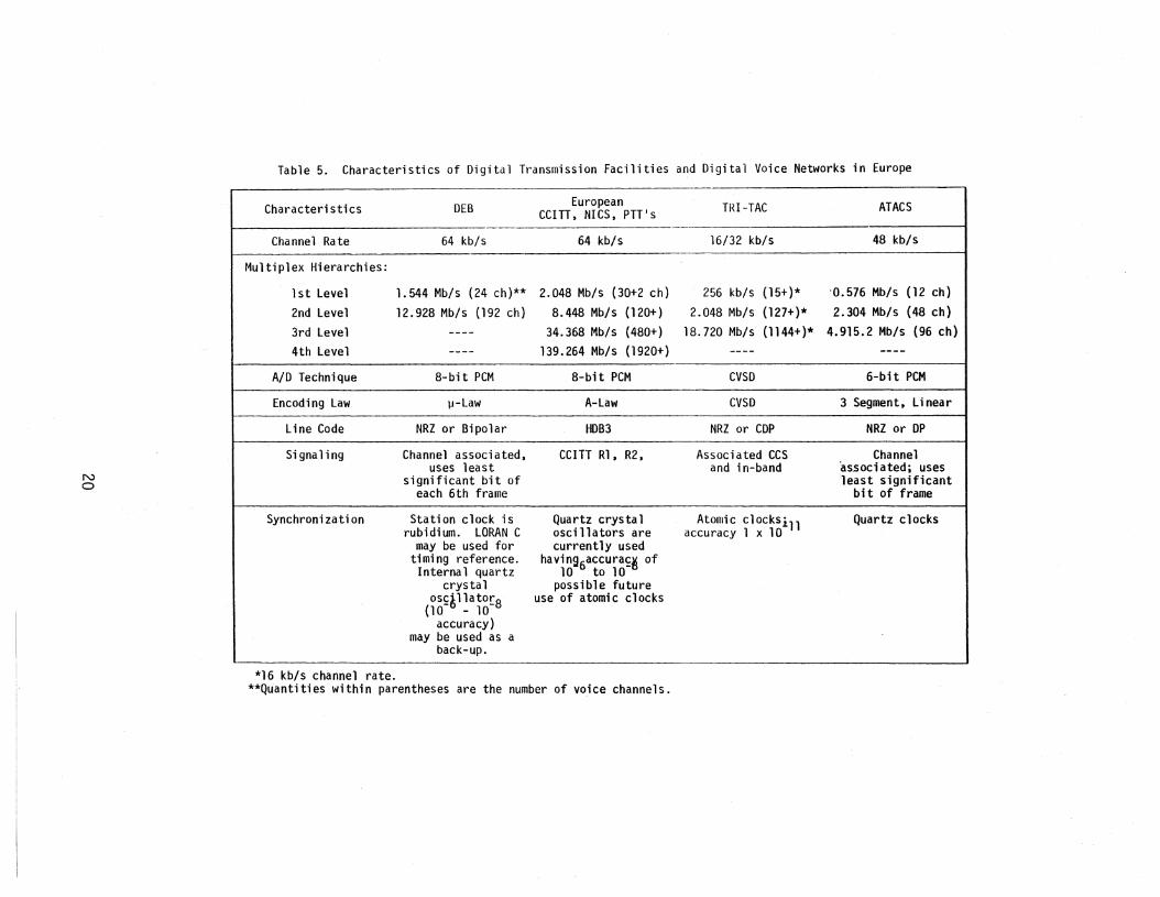
The difficulty in achieving either pipeline or end-to-end interoperabilityamong the various networks in the European theater can be seen by scanning Table5. This table itemizes some of the major parameters for DEB, TRI-TAC, ATACS,and NICS. The NATO Integl~ated Communication System will employ the EuropeanCCITT (International Telegraph and Telephone Consultative Committee) standards
19
No
Table 5. Characteristics of Digital Transmission Facilities a~d Digital Voice Networks in Europe
Characteristics DEB European TRI-TAC ATACSCCITT, NICS, PTTls
Channel Rate 64 kb/s 64 kb/s 16/32 kb/s 48 kb/s
Multiplex Hierarchies:
1st Level 1.544 Mb/s (24 ch)** 2.048 Mb/s (30+2 ch) 256 kb/s (15+)* '0.576 Mb/s (12 ch)
2nd Level 12.928 Mb/s (192 ch) 8.448 Mb/s (120+) 2.048 Mb/s (127+)* 2.304 Mb/s (48 ch)
3rd Level ---- 34.368 Mb/s (480+) 18.720 Mb/s (1144+)* 4.915.2 Mb/s (96 ch)4th Level ---- 139.264 Mb/s (1920+) ---- ----
AID Technique 8-bit PCM 8-bit PCM CVSD 6-bit PCM
Encoding Law ll-Law A-Law CVSD 3 Segment, Linear
Line Code NRZ or Bipolar HDB3 NRZ or CDP NRZ or DP
Signaling Channel associated, CCITT R1, R2, Associated CCS Channeluses least and in-band associated; uses
significant bit of least significanteach 6th frame bit of frame
Synchronization Station clock is Quartz crystal Atonrlc clocksil1 Quartz clocksrubidium. LORAN C oscillators are accuracy 1 x 10
may be used for currently usedtiming reference. having6accura~~ ofInternal quartz 10 to 10
crystal possible futureos~il1ator8 use of atomic clocks
(10 - 10accuracy)
may be used as aback-up.
*16 kb/s channel rate.**Quantities within parentheses are the number of voice channels.

that are used by the PTTls (Postal, Telephone, and relegraph). The table indicates that almost all of the parameters are different among the various networks.The task of achieving interoperability on a multichannel, end-to-end basis is aformidable one. Further details of the DEB, ETS, and TRI-TAC systems are provided in Appendix A.
2.3 Relation to Seven Levels of Interoperability Proposed by LaVeanLaVean (1980) defines an interoperability spectrum consisting of seven
levels th:at has been developed by the Defense Communications Agency" The sevenlevels o~ interoperability are:
1) s~parate systems,2) shared resources,3) ga teways,4) multiple entry points,5) conformal or compatible systems,6) completely interoperable systems, and7) same system.
The levels increase in degree of interoperability as the number o·f the optionincreases. The primary benefit of the "sharedresources" option is that anlIeconomy of scale ll may be~ achieved, e.g., the cost per voice channel may be significantly less if two or' more networks are sharing the same transmission link.An example of the shared resources would be the use of DEB links by both AUTOVONand AUTODIN networks.
True interoperability is achieved through the use of gateways. For example,a gateway may be provided between a tactical network and the DCS. Multiple entrypoints in the DCA interoperabili'ty hierarchy is simply an extension of the gateway concept. Numerous gateways (12 to 20 as defined by LaVean, 1980) would berequired for the interoperability level to be classified as multiple entry points.The number of gateways is increased primarily to enhance survivability.
Conformal or compatible systems is the next highest level in the hierarchy.The systems are not identical, but the system parameters are such that it iseasy to make the transition from one system to the other at the network inter-
faces. The completely interoperable level, on the other hand, requires an identical set of signaling formats, preemption protocols, etc. It requires that thesystem control elements be able to comnunicate with each other.
21

While the seven levels of interope,rability discussed above provide a logicalstructure for addressing the interoperability issue, much work remains to be donein applying this structured approach to actual network interfaces. A classifiedDefense Communications Agency -report provides guidance on u.s. policy on communications network interoperability. This guidance is not stated in terms of thelevel of interoperability, however. Consequently, most work has been concentratedon levels 2 and 3 (shared resources and gateways). In considering interoperability solutions for the far term (1990's and beyond), emphasis should be on thehigher levels of interoperability (conformal or c~mpatible systems and completelyinteroperable systems). The highest level (same system) may never occur becausethe rapid change of technology causes each network to evolve with time, and toIIl eap frog ll others in their implementation of new technology. It is not entirelyclear that the "same system ll level is a desirable goal becau-se of survivabilityconsiderations.
The Worldwide Digital Systems Architecture (WWDSA) study (DCA, 1981b) doesnot discuss the interoperability issue in terms of the seven levels. However,it is clear that in the recommendations made in the WWDSA study, higher levelsof interoperability are a key feature of the goal architecture. For example,Feature N of the goal architecture is to lIencourage common standards for all networks, where feasible, for improved interoperability.1I Feature Mis an lIimprovedinternetwork system control between DeS, tactical, and commercial networks ... 11.
Thus, the WWDSA goal architecture, although not related explicitly to the sevenlevel interoperability hierarchy, appears to be oriented toward the higher interoperability levels such as level 5 (conformal or compatible systems) or level 6(completely interoperable systems).
Table 6 relates the digital pipeline and end-to-end interoperability conceptsaddressed here to the seven interoperability levels discussed above. The digitalpipeline is one form of resource sharing. In this case it is the transmissionfacilities that are being shared. The correlation between the end-to-end interoperability concept and the seven-level hierarchy is a little less clear. Depending upon the number of gateways or entry points incorporated and the degreeof standardization of protocols, the end-to-end interoperability concept fallssomewhere between levels 3 and 5 as shown in Table 6. In levels 3 and 4, the
gateways must perform protocol conversions while in level 5 (conformal or compatible systems) some degree of standardization has been achieved which minimizesthe amount of protocol conversion required. An example of this might be in the
22

Table 6. Relationship to the Seven Levels of InteroperabilityIntroduced by LaVean
NW
Level
2
3.
4.
5.
6.
7
TerminologyUsed by LaVean
Separate Systems
Shared Resources
Gateways
Multiple EntryPoints
Conformal/CompatibleSystems
Conlp1ete1yInteroperable
Systems
Same System
Terminology Usedin this Report
Digital Pipeline
End-to-EndInteroperability
Full Interoperabilityfor all
Operational Modes(~~WDSA Goa 1
Architecture)
IDse (?)
Parameters Affected
Line code, bit rate,synchronization, security,and some technical control
'-
All of the above plus users'service features.

signaling systems. The ETS will utilize CCITT #7 common channel and Rl signaling while TRI-TAC can use a common channel signaling system unique to TRI-TAC.Information on CCITT #7 signaling can be found in CCITT (1981). A gateway interface (level 3) could be developed to perform signaling protocol translation. Forthe far-term it may be found desirable to use a standard signaling system whichwould be part of level 5 interoperability (conformal/compatible systems).
One purpose of Table6is to show an orderly evolution in the interoperability of two networks such as the DCS and TRI-TAC. The evolution is from a comparatively simple digital pipeline, through a much more complex, multichannel,end-to-end interoperability concept, to the goal 1995 Worldwide Digital SystemsArchitecture. The far far-term goal is the Integrated Defense CommunicationsSystem (IDCS) described by McKee (1982).
Having reviewed various types or levels of interoperability, the next taskis to discuss the requirements for the different levels of interoperability asthey have been identified in various DCA and Joints Chiefs of Staff (JCS) documents. This is briefly treated in Section 3.
3. REQUIREMENTSA white paper on communications interoperability prepared by the U.S. Army
Communications Command (ACC, 1980) concluded that:
II ••• specific requirements for interoperation, particularlybetween major systems/networks, and their equipments andprotocols, such as DCS-JMTSS, US-NATO, military-commercial,and combinations thereof, are largely unstated or inadequately defined today. II
The reason that specific requirements are not well-defined is that even thegeneral interoperability requirements are not fully agreed upon. The ACC whitepaper further states that:
II ••• unfortunately there is no unanimity on the degree ofinteroperation which is satisfactory and required. 1I
For example, it has been stated that sufficient interoperability between theDCS and TRI-TAC is achievable with a VF analog interface at the TTC-39 TRI-TACswitch. Others state that the interface should be at a digital multichannellevel. Some state that the digital transmission level of interoperability isneeded, but should be restricted to the case of the DCS serving as a transmission
24

backbone between separated tactical operational areas. A view is held that thereis no requirement for the use of tactical assets to restore connectlivity be.tweentwo disconnected portions of the DCS in a stressed environment.
The ETS will be a major portion of the European DCS in the late 1980'sandbeyond. However, the tactical/ETS interoperability requirements have not beendefined. Therefore, the DCS tactical interoperability requirements are statedonly in general terms.
Because of the widely varying points of view that have been encounteredduring the course ofthfs study, itis important to establish a baseline set ofDCS/TRI-TAC interoperability requirements as they have been stated in DCA andJCS documents. The unclassified reference documents reviewed that provide guidance on interoperability are DCA (1980), DCA (1981a), DCA (1981b), and Pound(1979). The classified documents reviewed were:
a) JCSMessage 20 2004Z December, 1979, liThe Joint MultichannelTrunking and Switching System ll
,
b) DCECTR 2-82, IIFY-1983/FY 1989 DCS RDT&T Program ll,
c) DCA report, IIDefense Communications System/European Communication System Interoperabi1ity Base1ine ll
,
d) DCA report, IIDe~fense Conmuni ca ti ons Under Stress (COMSTRESS)Phase II Report ll
,
e) DCA report, IIWor1dwide Digital Systems Architecture (WWSDAI)Transition Plan ll
,
f) DCEC TR 1-81, liThe DCS: FY, 1984 and Beyond ll,
g) DCEC TR 4-81, II Requ; rements and Overview of the Future DCS II ,and
h) DCEC TR 5-81, IIDeficiencies of the Baseline DCS II .
In the following sections, these documents will be used to show that thereare valid requirements for the interoperability of the DCS and TRI-TAC at boththe digital pipeline (transmission resource sharing) level and at the end-to-end(subscriber-to-subscriber) level. It will also be shown that requirements havebeen stated for multichannel interfaces, not merely single-channel, VF interfaces.Table 7 lists the general user requirements that are being addressed in thisreport. The following sections show the basis for the assertion that these arevalid user requirements.
25
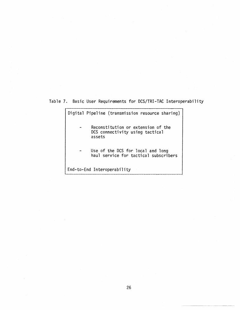
Table 7. Basic User Requirements for DCS/TRI-TAC Interoperability
Digital Pipeline (transmission resource sharing)
Reconstitution or extension of theDes connectivity using tacticalassets
Use of the DCS for local and longhaul service for tactical subscribers
End-to-End Interoperability
26
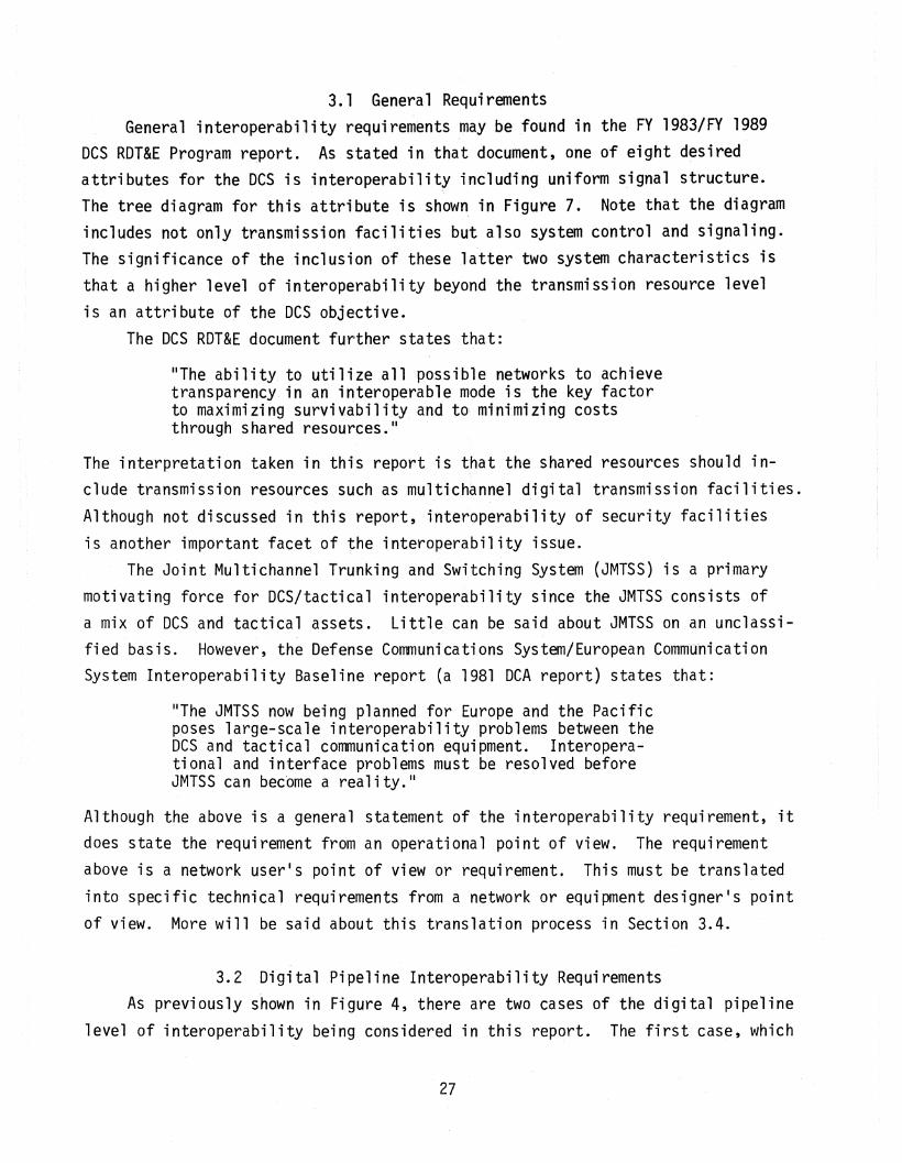
3.1 General RequirementsGeneral interoperabiltity requirements may be found in the FY 1983/FY 1989
DCS RDT&E Program report. As stated in that document, one of eight desiredattributes for the Des is interoperability including uniform signal structure.The tree di agram for thi s attri bute is shown in Figure 7. No·te that the di agramincludes not only transmission facilities but also system control and signaling.The significance of the inclusion of these latter two system characteristics isthat a higher level of interoperability beyond the transmission resource levelis an attribute of the DCS objective.
The DCS RDT&E document further states that:
liThe ability to utilize all possible networks to achievetransparency in an interoperable mode is the key factorto maximizing survivability and to~ mini.mizing coststhrough shared resources. 1I
The interpretation taken in this report is that the shared resources should include transmission resources such as multichannel digital transmission facilities.Although not discussed in this report, interoperability of security facilitiesis another important facet of the interoperability issue.
The Joint Multichannel Trunking and Switching System (JMTSS) is a primarymotivating force for DCS/tactical interoperability since the JMTSS consists ofa mix of DCSand tactical assets. Little can be said about JMTSS on an unclassifi ed bas is. However, the Defense Communi ca ti ons Sys tern/European Comrnuni ca ti onSystem Interoperabi1ity Ba.seline report (a 1981 DCA report) states that:
liThe JMTSS now being planned for Europe and the Pacificposes large-scale interoperability problems between theDCS and tactical communication equipment. Interoperational and interface problems must be resolved beforeJMTSS ca n bec'ome a rea1i ty . II
Although the above is a general statement of the interoperability requirement, itdoes state the requirement from an operational point of view. The requirementabove is a network user's point of view or requirement. This must be translatedinto specific technical requirements from a network or equipment designer's pointof view. More will be said about this translation process in Section 3.4.
3.2 Digital Pipeline Interoperability RequirementsAs previously shown in Figure 4, there are two cases of the digital pipeline
level of interoperability being considered in this report. The first case, which
27

'"'lRort.R"81l It, 'NClUU'N(; meuno SIGtf"l S,RtJCt",,(
. I I I IIlfl£llJr.tnt rttXllILt "MO"ROIlA""" tftt£ROrtR"'Ul'"
Iftf(RfN:{ UNit 1tl'1IOR~ rl-, ".", Olll"
ISl.ftm[ • 'WORtS
r---, I , I"IrMn Soft.,. ',otoco',Int'!tf.c tnt
tontro1 S''''~y!: tetll$
~1'gn.1In9 SysteMI tl....nls
~I
"'dets 0lI1 of ,.,.... I ....
'roIklst tentr.''oUbael 'htt',",t~
tnte~hdn" ,,"Tn"5",h~ '0" 'Mr!,ff"~:t:;t;~~:Yn:t:.. I ~... Inter,.el", ",'n Oote '_'no"
"nalo" "/0 --,--, rl,fr .tod·
r--h.:I . Cod'"" r...... t . '. ..1tt! ,ott "~otocoh st"nd"r" .fft$
N1I CYSlI Ootp.t
PllCld. ----.I-, POC~d' '" "hi .. .. ,
Prnl""nh st...... "...10<:'"
'nterf"cfn"S..curHy
r-hkey ('I,lolt"'" I\cquhl
OhtrtbuUD" Duty !;ynefutnf
N00
Figure 7. Tree diagram on interoperability including unified signal structure.

might be called the reconstitution case, is when tactical transmission facilitiesare used to provide connectivity between separated DCS nodes. The second caseis the use of DCS transmission facilities' to provide a transmission backbone forg~bgraphicallY separated tactical operational areas.
The COMSTRESS (Communications Under Stress) report, DCS FY 1983/FY 1989RDT&E Program report, the' DCS interoperability baseline report, and the DEBManageme,nt Engineering Plan (DCA, 1980) all support the contention that thecapability for tactical assets to reconstitute the DCS is a valid requirement.
One of the COMSTRESS study reconmendations is that:
IIReconstitution assets should consist of a mix of both DEBand tactical assets."
The requirements stated in COMSTRESSare validated requirements. The DeS RDT&EProgram report states that a thrust for integrated design and system control isto:
IIDevelop the control interoperability criteria and interfacecapability for interoperation between the Des control processessubsystem and those of conmon carriers, tactical systems, andallied systems to enable servicerestorals through non-DCSresources. II
The DCS interoperability baseline report states that:
"tactical equipment could, if it were interoperable, be deployedto reconstitute the damaged DCS in less time than fixed assetscould (even if available) be deployed and installed."
The concept of using the DCS to interconnect geographically separated tactical operational areas is introduced in the DEB Management Engineering Plan (DCA,1980). Tactical elements will be provided direct access to the DEB through theTactical Interface Facility (TIF). The TIF is to provide interconnect capabilityat VF, 1.544 Mb/s, and 12.928 Mb/s. The existing wideband interface modules forthe first level DEB multiplexer IIcould be used for tactical data rates of 256 kb/sand 512 kb/s when the requisite timing and buffering subsystems are deployed. II
The DEB MEP explicitly states that:
"Tactical interconnects are required to provide an access tothe DCS backbone for tactical elements and for reconstitutionin the event of wholesale destruction of the DCS. II
29

This establishes the requirement for the use of the DCS to provide backbone transmission services for connecting tactical nodes, as well as for the use of tacticalassets for re-establishing DCS communication services.
3.3 End-to-End Interoperability RequirementsThe trend in military communications networks is to evolve toward an all
digital network. The primary motivating factor is th~t voice encryption is morereadily accomplished in a digital system than in an analog system. Despite thefact that more voice circuits can be packed into an analog wideband channel (suchas that provided by the Bell system1s AR-6A SSB-AM radio), military transmissionfacilities are evolving toward an all digital system for security reasons. Thelong-range goal architecture is that described in the DCA Worldwide DigitalSystems Architecture (WWDSA) reports. Some of the key baseline deficiencies thathave been identified by the l~WDSA committee in their final report are:
II poor interoperability with tactical systems except at VF,II
IIsl ow restoration/reconstitution,1I
"inadequate interoperabilityll for secure voice, and
"inadequate information transfer between networks for systemcontrol. II
These deficiencies are in relation to an objective architecture that among otherthings requires end-to-end interoperability between networks, muitichannel digital interfaces, and the exchange of system control information between fullyinteroperable networks.
The current OCS RDT&E Program document (OCEC TR 2-82) also supports theseend-to-end interoperability objectives. Part of the thrust for the secure voiceimprovement program is to:
"Develop specification and standards for secure interfaces withtactical, NATO, and civil networks to provide end-to-end securecommunications across network boundaries for critical commandand control users of the DCS. II
Furthermore, one of the thrusts for AUTOVON/DSN is to:
"Develop a DOD common channel signaling (CCS) concept to includeinteroperability with commercial and tactical systems, dynamicrerouting and provision for disseminating system control information. 1I
30

The deficiencies ide1ntified by the WWDSA committee as well as the RDT&Ethrusts described above plus on-going RDT&Eprojects (DCEC TR 2-82) support thecontention that general requirements" have been stated for high-level, end-to-end,multichannel interoperability between the DCS and U.S. tactical, NATO, and alliedcountry telecommunication networks. As noted in the DeS baseline interoperabilitystudy (a 1981 DCA report) the distinction between the DCS and tactical worlds isbecoming clouded. As the division line between the two becomes less distinct,higher levels of communications interoperab;lity are required. The end-to-endlevel of interoperability is therefore viewed in this report as a valid requirement. The emphasis in this report is on DCS interoperability with TRI-TAC. Abroader examination of the interoperability issue would also include DeS interoperability with NATO, PTT and host nation military and civil communicationsystems. Such a broad purview is outside the scope of this study.
3.4 Mapping of General User" Requirements intoTechnical Specifications
To this point the interoperability requirements have been discussed in general terms and primarily from an operational or user's point of view. As notedin the introductory section of this report, the ultimate objective of "this studyis to identify R&D programs needed for the present DeS to evolve toward a goalDSN or eventually WWDSAthat is fully responsive to the users' or operators'requirements. The task then is to translate these general operational requirements into more specific technical requirements. The focus here will be primarilyon the radio, multiplexer, or modem requirements as these are the assigned responsibility of the U.S. Army Communications Systems Agency.
Figure 8 sets the framework for performing the translation of general requirements into technical requirements or specifications for multipliexers orradios. The users and network operators originate all requirements for communications network services. The network designer or equipment designe'r must consider many other factors in designing a network or equipment that satisfies theusers' or operators' requirements. First of all, the characteristics of existingequipment or systems must be considered. Because of the large amount of existingequipment in the inventory, communications systems must gradually evolve. Itsimply isn't economically feasible to start over with an entirely new system.The designer must also consider regulatory requirements. For example, frequencyallocations, bandwidth requirements including spectral shaping, spectral efficiency
31

w;"\)
SYSTEMSPECIFICATIONSFORMULTIPLEXERS
----SYSTEMSPECIFICATIONSFORRADIOS
Figure 8. Factors that have an impact on radio and multiplexerspecifications.

in terms of bits/second per hertz, and power limitations are all radio paramet~rs
that must comply with specifications promulgated by regulatory agencies. Theavailability of new technology also affects the design of new systems, radios,or multiplexers. The operating environment also is a major influence. Theoperating environment includes such things as flat and multipath fading, interference and jamming. The expected fading or jamming environment, obviously,greatly influences the specification ·of radios.
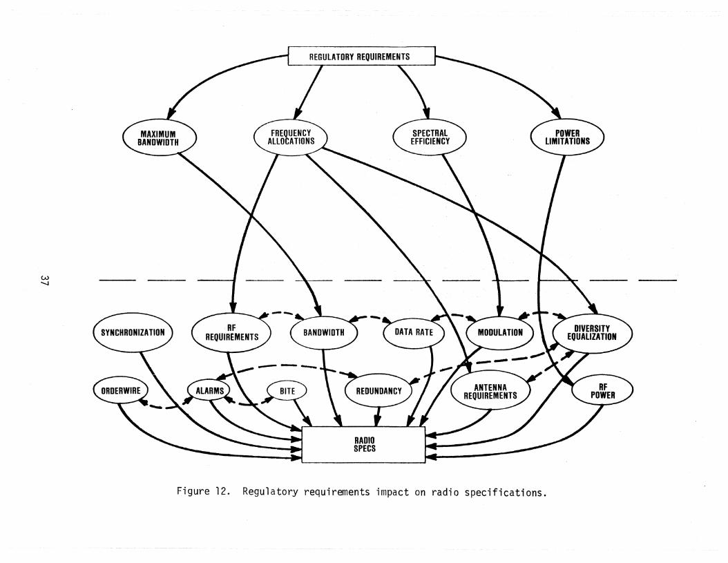
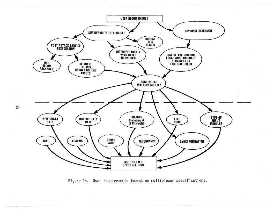
Figures 9 through 13 are an expansion of Figure 8 for radio specificationwhile Figures 14 through 16 are an expansion for multiplexer specification. InFigures 9 through 13, the bottom portion of each figure contains the major parameters that must be specified for radios. The dashed lines indicate parametersthat are closely related. The translation of users· and operators· requirementsinto radio specifications is shown conceptually in Figures 9 and 10. Figures 11,12, and 13 depict the impact of new technology, regulatory requirements, and theoperating environment on radio specifications.
Some elaboration is needed on Figure TO. The network operator ;s interestedin achieving interoperability from a logistics point of view. The operator isalso interested in minimizing cost. Efficient utilization of the spectrum ortransmission resources is one method of minimizing costs. McKee (1982) statesthat the major cost factor in the DeS as a whole is transmission, not switching.The DeS RDT&E Program (DCEC TR 2-82) and WWDSA (final report and transition planreport) also indicate the importance of reducing transmission costs. There arethree technical approaches to reducing transmission costs, namely:
high efficiency modulation techniques (high bits/second perhertz ratio),
efficient voice digitization, and
digital speech interpolation (OSI).
Amajor attribute of the future DCS as stated in the DCS RDT&E five year plan(DCEC TR 2-82) is efficient spectral utilization. One of the DCS deficiencies/drivers for this attribute is Ilinefficient use of transmission channels, e.g.,inefficient voice A/D with high rate 64 kb/s PCM. II One of the alternativesdeveloped later in Section 5 is responsive to the requirement for efficientspectral utilization as well as the DCS/TRI-TAC interoperability requirement.
33

w~
c .. I
RADIOSPECS
COVERAGE EXTENSION
Figure 9. User requirements impact on radio specifications.

wU"I
Figure 10. Network operator requirements impact on radio specifications.

wm
ALL RADIOSUBSYSTEMS
--- .......
VLSICVHSIC
NEW MODULATIONTECHNIQUES
• 64·QAM• SSB-AM• SPREAD
SPECTRUM
Figure 11. New technology impact on radio specifications.
w-.......
RADIOSPECS
Figure 12. Regulatory requirements impact on radio specifications.

wco
JAMMING ENVIRONMENT
ENVIRONMENT
Figure 13. Operating environment impact on radio specifications.
W\.0
RECON OFTHE DCS
USING TACTICAL
~
MUlTIPlEXERSPECIFICATIONS
Figure 14. User requirements impact on multiplexer specifications.

EFFICIENTSPECTRUM
UTlllZAliON
MULTIPLEXERSPECIFICATIONS
OPERATOR REQUIREMENTS
~o
Fi gure 15. Network operator requirenlents impact on mul ti pl exerspecifications.
+::=----'
MULTIPLEXERSPECIFICATIO"S
Figure 16. New technology impact on multiplexer specifications.

3.5 Specific RequirementsTable 8 lists DEB/TRI-TAC interoperabi1ity requirements as they are stated
in the DEB Management Engineering Plan (DCA, 1980). A Tactical Interface Facility(TIF) with interconnects at VF, 1.544 Mb/s, and 12.928 Mb/s is a stated requirement. Interconnects between DEB and TRI-TAC could be provided at 256 kb/s and512 kb/s (both are TRI-TAC group rates) through the FCC-98 first level multiplexer multiple rate, wideband data input module if necessary timing and buffering is provided. This buffering and timing interface has not been developed.
The WWDSA specifies the following standard transmission rates:
75 x 2n b/s16 kb/s64 kb/s
256 kb/s288 kb/s512 kb/s576 kb/s
1,544 kb/s2,048 kb/s
1 < n < 8
Any new multiplex equipment should support one or more of these transmissionrates. Higher transmission rates such as 8.448, 34.368, 139.264 Mb/s in theEuropean multiplexer hierarchy, 6.312, 44.736, and 274.176 Mb/s in the NorthAmerican multiplexer hierarchy, 9.36 and 18.72 Mb/s in the TRI-TAC multiplexerhierarchy, and 12.928 Mb/s in the DRAMA hierarchy have not been specified inthe WWDSA reports.
4. EXISTING DCS/TACTICAL INTEROPERABILITYThe current European Defense Communications System consists of AUTOVON,
AUTODIN, and AUTOSEVOCOM. It is expected that the European Telephone Systemwhich is currently being implemented will eventually merge with the EuropeanAUTOVON to form the European portion of the Defense Switched Network (DSN).Plans for interfacing the ETS and tactical systems are incomplete. In thetactical world, the existing system for Army tactical communications is ATACS.
42

+::=w
Table 8. DEB/TRI-TAC Interoperability Requirements
- Designated DEB sites will be equipped with a TacticalInterface Facility (94 sites; up to 48 tactical voicecircuits per site)
Interconnects will be at VF, 1.544 Mb/s, and 12.928 Mb/s
- 256 kb/s and 512 kb/s tactical data rates could be usedif necessary timing and buffering is~provided
- Modifications of DRAMA equipment to handle 288 kb/s,576 kb/s, and 2.048 Mb/s are being considered
- U.S. Army is responsible for providing the tacticalinterface capability for DEB
Reference: DEB Management Engineering Plan (DCA, 1980).
~~wever, TRI-TAC equipment is expected to be fielded in the near future according to plans received from the TRI-TAC office.' The emphasis in this section onexisting DCS/tactical interoperability will therefore be AUTOVON and TRI-TAC.
In this section, the meaning of the phrase "existing interoperability" hasbeen extended to include capabilities that are planned for the very near future.Since TRI-TAC equipment has not been placed in operation in the field, there obviously is no "existing" interoperability between TRI-TAC and the DCS today. However~ the specifications for TRI-TAC large circuit-switches (AN/TTC-39) includerequirements for interfacing with an AUTOVON switch. This TRI-TAC/AUTOVON interface is considered to be the baseline "existing" capability for TRI-TAC interoperability with the DCS.
Section 4.1 is a brief description of the AN/TTC-39 capability for interfacing with AUTOVON loops~ trunks, and switches. This is followed in Section4.2 by a discussion of additional interface capabilities that will be needed asthe European DCS evolves.
4.1 AN/TTC-39 and AUTOVON Interface CapabilityThe TRI-TAC specifications for the AN/TTC-39 central office circuit-switch
require that the switch be compatible with the AUTOVON numbering plan, AUTOVONtrunk signaling, and AUTOVON loop signaling (TRI-TAC~ 1982a and TRI-TAC~ 1982b).The AN/TTC-39 switch is also required to be able to act as an AUTOVON switch insignaling to and from PBX's (Private Branch Exchanges). These requirements willbe briefly described in the following subsections.
4.1.1 Numbering PlanOne type of numbering plan used in the AN/TTC-39 is of the form (NYX) NNX
XXXX where:
N = 2 - 9~
X = 0 - 9, andY = 0 - 1.
Other numbering plans for the TTC-39 switch exist. However, the numbering plandescribed above is of the same format as AUTOVON, and therefore is of primary
interest in this report. On calls from an AUTOVON area to a tactical area, orvice versa, each number exclusive of prefixes consists of 7 or 10 digits. Ifcalls originate and complete within an AUTOVON area code only seven digits are
44

required (theNYX area code is not dialed). The AUTOVON and AN/TTC-39 switchesdistinguish la-digit numbers from 7-digit numbers by the fact that every areacode has an a or a 1 as the second digit, but the NNX switch code never has an
o or 1 as the second digit.In addition to the 7- or la-digit basic numbering plan, there is an optional
PR prefix where the "p" is one of four special characters used to denote thelevel of precedence. Absence of the lip" indicates a routine call. The IIRII
represents a control code' used to signify special service and routing requests.Detailed information on the lip" and IIR" c·odes may be found in the Overseas
AUTOVON network Switching Plan (DCA, 1967). For AUTOVON calls routed throughTRI-TAC, the integrity of the PR prefi~ is preserved; i.e., it is transmittedon the outgoing AUTO VON trunk group unchanged. The tactical AN/TTC-39 switch
uses the prefix for subscriber and transmission compatibility checks and todetermine routing restrictions. For·AUTOVON calls generated by tactical AN/TTC39 subscribers it generates and transmits any prefix required to extend the callinto AUTOVON.
4.1.2 AUTOVON/TRI-TAC Switch Trunk Signaling and Subscriber Loop SignalingThe signaling between the AN/TTC-39, when operating as an AUTOVON switch,
and other AUTOVON switches use analog trunk signaling that complies with the DCACircular on AUTOVON switching (DCA, 1967). The signaling is in-band, singlefrequency (2,600 Hz) for supervision and MF 2/6 (multifrequency) in-band confirmation or nonconfirmation address signaling. In the confirmation signaling mode,AUTOVON responds to a trunk seizure by the AN/TTC-39 switch by sending a keypulse (KP) signal. Upon receipt of KP, the AN/TTC-39 sends KP to the AUTOVONswitch. The AUTOVON switch sends interdigit (ID) and the AN/TTC-39 then sendsthe first digit of the addressing sequence (P + R + NYX + NNX + XXXX). Aftereach digit is sent by the AN/TTC-39, the AUTOVON confirms with interdigit. Uponcompletion, the AUTOVON switch sends the end of signaling (ST) digit to the
AN/TTC-39 switch. After completion of the address signaling, the AN/TTC-39 takesno further action unless a busy, pre-emption, or release signal is initiated.AUTOVON completes routing of the call. The release cycle with AUTOVON is completed by applying the correct supervisory tone conditions to the trunk and
marking the trunk idle. The AN/TTC-39 recognizes the trunk busy (T8), line busy(LB), and pre-emption signals generated by AUTOVON and specified in DCAC-370-V185-7(DCA, 1967).
45
It is possible to program any trunk group for MF 2/6 nonconfirmation signaling. In this Jrlode, the destination switch does not respond with a confirmationinterdigit signal for every digit sent by the originating switch. The digitpulse is 70 ~ 15 ms wide.
The AUTOVON telephone set is a four-wire unit, requiring common battery (48V,60 rnA nominal) power and utilizes DTMF (dual tone, multifrequency) signaling, dcloop supervision, and dc loop controlled ringing. This mode of operation can
also be used with the AN/TTC-39 switch (TRI-TAC, 1982a). Through use ofa specialadapter on long loops, the telephone set may be converted to local battery, withE&M (rIceive and trans~it) supervision. Application of a single frequency (SF)unit in conjunction with the adapter provides 2,600 Hz in-band supervision forlonger loop transmission and carrier interface.
Further information on the trunk and loop signaling maybe found in TRI-TAC(1982a, b), and DCA (1967). The brief overview provided above is presented toshow that the AN/TTC-39 switch can be operated in an AUTOVON switch mode as faras trunk and loop signaling are concerned. The AN/TTC-39 specifications alsorequire the AN/TTC-39 switch to be able to act as a PBX and signaling to an .AUTOVON swi tch.
4.2 Requirements Not Satisfied by ExistingTRI-TAC/AUTOVON Interoperability
The existing tactical/DCS interoperability (which currently is limited toAUTOVON/TRI-TAC interoperability) described above has several deficiencies ashas been noted in WWDSA documentation (DCA, 1981b) and the DCS RDT&E Programreport (DCEC TR 2-82). These deficiencies include:
poor transmission interoperability except at VF (DCA, 1981b),
need to develop II standards, for secure interfaces with tactical, NATO, and civil networks to provide end-to-end securecommunications act:'oss network boundaries" (DCEC TR 2-82),
need to develop a DOD common channel signaling (CCS) systemconcept to include interoperability with commercial andtactical systems, dynamic rerouting and provision for disseminating system control information (DCEC TR 2-82), and
a need to develop the system control interoperation betweenthe DCS control subsystem and those of common carriers, tactical subsystems, and allied systems to enable service restorals through non-DCS resources (DCEC TR 2-82).
The following paragraphs provide some elaboration of these deficiencies.
46

The direction in which defense corrmunications networks are evolving istoward all digital switching and transmission. The Worldwide Digital! SystemsArchitecture (WWDSA) documentation (DCA, 1981b) supports this contention. Onemotivating factor is the ease of digital encryption compared to analog. ThelIexisting ll interoperability described in the previous section is not supportiveof the goal WWDSA architecture, which specifies digital transmission, or ofend-to-end secure communications defined as a thrust in the DCS RDT&E Program.
The European AUTOVON and the European Telephone System (ETS) are likely tomerge into a single network by the late.1980·s. According to a draft ETS systemarchitecture document the goal ETS will utilize the CCITT #7 Common Channel Signaling. The TRI-TAC architecture utilizes its own unique version of common channel signaling protoGol. The two signaling structures have been develloped independently of each other. It is likely that they may be made to interoperate atleast for some signaling functions. This problem will be addressed ifn Section6, but a full investigation is outside the scope of this report. The point tobe made here is that even though existing interoperability between AUTOVON andTRI-TAC includes signaling, the system that will service most strategic usersin Europe in the late 1980's and beyond will be ETS, not AUTOVON. TheETS andTRI-TAC signaling systems are not currently interoperable.
Interoperable system control is required for network managers to efficientlycontrol network resources. This is especially important in a stress environmentwhere assets from other networks, such as TRI-TAC, may be utilized to restorecommunication services. Efficient usage of such reconstitution resources requires an interoperables.ystem control subsystem. Types and formats of systemcontrol information between the DeS and TRI-TAC should be made compatible.
In summary, a low level of interoperability currently exists between AUTOVON and TRI-TAC. However 'I in comparing the existing c.apability against therequirements stated in Section 3, several deficiencies have been noted. Alternatives for resolving the poor transmission interoperability will be describedin Section 5 on digital pipeline interoperability. The common-channel signalingand system control defici€~ncies will be discussed more fully in Section 6 onend-to-end interoperability. Alternative concepts for resolving the end-to-endinteroperability deficiencies will be briefly discussed.
47

5. DIGITAL PIPELINE INTEROPERABILITY ALTERNATIVES AND EVALUATIONThe digital pipeline concept was introduced in Section 2. Requirements for
this level of interoperability were described in Section 3. In this present section, alternative concepts for satisfying these requirements are discussed. Thesection concludes with a qualitative evaluation of the alternatives and a recommendation for a suggested approach for achieving digital pipeline interoperability.
As noted previously in Table 4, the system characteristics that are ofprimary importance for the digital pipeline level of interoperability are:
bit rate,line code,error control,timing and synchronization,technical control, andsecurity.
The bit rate is emphasized here rather than the number of channels because thedigital pipeline is impartial to the type of information being transmitted.The line code, although essential to interoperability, will not be discussed indetail, because translations between different line codes can be easily implemented (see Appendix C for a discussion of line codes). Timing, technical control, and interfacing with encryption devices are all important system characteristics that must be addressed. These parameters must be considered regardless of how the digital pipeline interoperability is achieved. The main questionthat needs to be addressed is the question of where in the transmission chainshould the transmission level of interoperability between the DeS and TRI-TACshould be achieved. Should it be at the first level of multiplexer, secondlevel, or at the radio? Figure 17 indicates some possible points for digitalpipeline interoperability. This figure is generic in the sense that it appliesto both the DCS/TRI-TAC/DCS and TRI-TAC/DCS/TRI-TAC digital' pipeline cases. Acorollary to the point-of-interoperation question is the question of what arethe transmission bit rates that should be used. These questions will be addressed for each of the alternatives described in Sections 5.2, 5.3, and 5.4.
Before turning to these alternatives, however, it is appropriate to discusssome related work for interoperability that has either been proposed or is inthe development stage.
48

(j) cv @ Q) ® (j)
~\.0
SWITCH RADIO
--z,. -
RADIO SWITCH
Figure 17. Possible interface points for digital pipeline interoperability.
5.1 Related Work on Pipeline InteroperabilitySeveral different government or industrial organizations have performed
studies, made proposals, or constructed engineering deve19pment models forachieving interoperability between the DeS and one or more other networks suchas TRI-TAC, NATO, etc. Because specific requirements have 'not been identifiedand because of some overlap in organizational responsibilities, there is acertain amount of overlap in the objectives of these programs. The existenceof these programs was made known to the author well after the ITS study wasinitiated.
5.1.1 Joint DCA and TRI-TAC Program Office Approaches to InteroperabilityThere are three approaches to interoperability that have been agreed upon
between the Systems Division in the TRI-TAC Program Office and the TacticalInterface Branch in DCA. These approaches are:
1) VF analog (described in Section 4 as existing capability),
2) message switch interface using the tactical ICD-015 (Interface Control Document) standard, and
3) a digital interface.
The digital interface is to be at 512 kb/s between the TRI-TAC Trunk Group Multiplexer (TGM) and the DCS FCC-98 first level multiplexer (see Appendix A for details on these multiplexers). This interface is to provide a capability forTRI-TAC-through DCS-to-TRI-TAC only. The converse capability of DCS-throughTRI-TAC-to DCS is not being addressed. There is a requirement for the lattercapability, which corresponds to the case of using tactical assets to reconsti
tute the DCS. As noted in Section 3, theCOMSTRESS report (DCA report publishedin 1982) states that reconstitution assets should consist of a mix of both DEBand tactical assets.
5.1.2 DCS/Tactical Interface FacilityA DCS/Tactical Interface Facility (DTIF) concept originated by the u.S.
Army Center for Communications (CENCOMS) has been forwarded to various DODagencies for comment. The DTIF concept is depicted in Figure 18. This facility
would be capable of providing an interface for either tactical through DCS orfor DCS through tactical. Unlike the digital interface described in the preceding subsection, the DTIF provides for rerouting DCS traffic through tactical
50

I• TACTICAL ~ • « DeS ~ I
AN/TSO-III
4
COP - CONDITIONED DIPHASEDP- DIPULSEBP- BIPOLAR
NRl- NOI-RETURI-TO-ZEROLScDM - LOW SPEED CABLE DRIVEN MODElHSCOM - HIGH SPEED CABLE DRIVEN MODEM
GM - GROUP MODEMMGM - MASTER BROUP MULTIPLEXER
eRF - CHANNEL REASSIGN.ENT FACILITYTT - TII-TAC
ATAes - ARMY TACTICAL COMMUNICATIONS SYSTEM
AN/FCC·.
TACTICAL THROUGH DCI ...------DCS THROUGH TACTICAL
ACCESS
DIGITAL
SYSTEM(DACSI
CROSS ·CONNECT
1644 kb/l
2048 kbtl
1544 kb/.
2048 kb/s
30-8 BIT PCM CHANNELS
24.8 BIT PCM CHANNElS
1162 kb/.
518 kb/. 12304 kb/ll
512 kb/l
518 kb/.
1162 kb/'12304 kb/ll
24-8 BIT PCM CHANNELS
12-8 BIT PCM CHANNELS
15-32 kb/. CVSO CHANNELS31-16 kb/l cvsn CHANNELS
15-32 kbtl cvao CHANNELS31-18 kb/l cvsn CHANNELS
VI.....J
Fi gure 18. DeS/tactical interface facility.

transmission facilities as well as for the rerouting of tactical traffic throughDCS transmission facilities. The 576 kb/s and 1,152 kb/s transmission rates arecompatible with the Army Tactical Communication System (ATACS) as well as withTRI-TAC. The 1,152 kb/s transmission rate is not one of the standard rates ofthe WWOSA architecture, however. The proposed use of the Digital Access andCross-Connect System (DACS) is to provide a DCS interface with the DTIF.
The OACS is not an integral or necessary equipment for achieving the tactical/DCS interoperability. The DACS is normally used for switching individual channels of a Tl carrier to a different Tl carrier. This is illustrated in Figure19. Up to 127 DS-l signals (3,048 DS-O voice channels) can be accommodated byDACS. Its usefulness is in being able to switch DSO channels (64 kb/s) from oneDS-l group (1.544 Mb/s) to another OS-l group without conversion back to analog.This is accomplished through time slot interchange chips. The DACS can also beused for switching OS-l groups from one port to another.
5.1.3 Digital Channel Efficiency ModelThe Digital Channel Efficiency Mo'del (DCEM) is responsive to two require
ments of the DCS. The requirements are:
1) to provide interoperability between the DCS and networks usingthe CCITT European Standards (such as the NATO Integrated Communication System (NICS) and the PTT networks), and
2) to reduce transmission costs through efficient spectrum utilization.
A discussion of the DCEM is pertinent to this report because some of the conceptsincorporated in the OCE~1 could also be utilized for DCS/TRI-TAC interoperability.In the DCEM concept, Digital Speech Interpolation (DSI) is used to increase thecapacity of a digital transmission facility. At the same time, the DCEM providesnodes for transmission interoperability between the DCS and NATO.
Figure 20 depicts the eight operational modes of the DCEM (RADC, 1980). Thefirst three modes are compression modes, the next two are rate conversion modes,and the final three are format conversion modes. For example, mode A is a compression mode in which two 24 channel, 1.544 Mb/s terminals (03 channel banks)are compressed by the DCEM using DSI techniques into a single 1.544 Mb/s carrier.
This compression mode is designated as 48/24/48~ i.e., 48 source channels are
compressed into 24 channels for transmission and then expanded into 48 channelsat the destination. The three compression modes of the DCEM are:
52
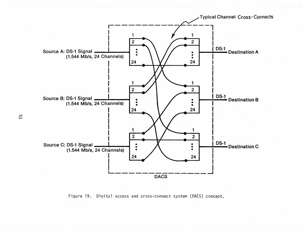
Typical Channel Cross-Connects
05-1I . Destination A
2
1
2
2
•••
1
•••
1
24
24
•••
•••
2
2
2
1
1
1
24
24
r----------III
05·1 D·· B...--1-- estlnatlon
IIIIII
Source C: OS-1 Signal _: : OS-1 Destination C(1.544 Mb/s, 24 Channels) • • I
I 24 24 II II IL--------~---~__ __J
DACS
Source A: 08-1 Signal ' I
(1.544 Mb/s, 24 Channels)
IIIII
Source B: OS-1 Signal I I
(1.544 Mb/s, 24 Channels)
IIIIII
CJ'1W
Figure 19. Digital access and cross-connect system (DACS) concept.

A. 48/24/48 48CHAN. 48
CHAN.
B•. 48/30/43
c. 30/24/30
D. 24/30/24
E. 30148/30
F. 24124/30(241
G. 24/30/30(24'
48CHAN..
30CHAN•.
24CHAN•.
allCHAN.
24CHAN.
24CHAN.
~.. DeEM ,. DCS IDCat~__ 3J188 Mb/s _
~ T1__1 DCEM~
==L.:J 1.544 Mb/S-..-_
E-1 DC~M 1-.tD48-E1-M-b/-.·-----B
,48CHAN.
30CHAN.
24CHAN~
30CHAN.
24 CHAN.EQUIPPED
24 CHAN.EQUIPPED
if. 30/48/48(301 30CHAN.
30 CHAN.EQUIPPED
Figure 20. Digital channel efficiency model (DeEM) operationalmodes.
54

48/24/48,48/30/48, and30/24/30.
The latter two compression modes provide interoperability between the DeS andthe CCITT European standard (30 voice channels, 2.048 Mb/s).
In the rate conversion modes (modes Dand E), the incoming bit stream issimply stuffed up to the desired rate by adding framing and fill bits to eachframe of data. The rate conversion mode is impartial to the data format, whichallows the transmission of PCM voice encoded bit streams, encrypted PCM, computergenerated data, etc. The rate conversion ~odes are:
24/30/24 and30/48/30.
In the format conversion modes (modes F, G, and H), the D5-1 signal formatof a D3 channel bank (CCITT North American Standard) is converted to the CCITTEuropean Standard and vice versa. This conversion process includes compandingconversion, encoding converston, signaling conversion, and framing pattern conversion. The D3 channel bank uses ~-law companding, inverted signed magnitudeencoding, and two 667 b/s in-'band signaling channels per voice channel. TheCCITT European Standard uses A-law companding, signed magnitude encoding withalternate digit inversion, and four 500 b/s out-af-band signaling channels pervoice channel. The companding conversion (A-law to ~-law) and vice versa canbe achieved through a simple table look-up. The format conversion modes are:
24/24/30 (24),
24/24/30 (24), and30/48/48 (30).
In these modes, 'the full capacity at the destination end is not used. For example, in the 24/24/30 (24) mode, only 24 of the 30 channel slots available at thedestination terminal are utilized, as indicated by the number in the parentheses.
The compression operating modes are the most complex. One problem with anyOSI system is how to handle the situation where the number of active speech channels exceeds the number of traffic channels. One approach used in some DSI
systems is freezeout which is the truncating or clipping of the speech until achannel becomes available. Another approach is to delay the speech burst untila channel becomes available. This results in nonuniform time gaps between
55

speech bursts rather than the original, natural time gaps. A third approach isto steal the least significant bit of other channels. This reduces clipping atthe expense of signal-to-noise ratios of the other channels. A fourth approach,which is the one used,in the DCEM, is to use speech compression during periodsof high channel activity.
The speech compression used in the DCEM is Adaptive Differential Pulse CodeModulation (AOPCM). During periods of low-channel activity the channel is encoded using 8-bit PCM. During periods of high channel activity the channel isencoded using ADPCM. The number of bits used for ADPCM is from 7 to 3 dependingupon the channel activity. Systems incorporating both OSI and ADPCM have beeninvestigated by other authors. DINeil (1978) and other researchers at NorthCarolina State University conducted research that included the development of aprototype system called the Digroup Data Reduction (DDR) System. The DDR wasthe forerunner of the DCEM. Recent papers by Yatsuka (1982a, b) and Langenbucher(1982) are indicative of DSI/ADPCM systems in the nonmilitary sector.
Three functions that the DCEM must perform in the compression modes are:
1) detection of channel activity and the subsequent discrimination between speech ~nd voice-band data,
2) generation and transmission of channel assignment informationto the distant receive, DCEM, and
3) the coding of speech channels using ADPCM with fewer than 8bits.
Channel activity is determined by monitoring the short-term power level of eachchannel. If the power level does not exceed a specified threshold, the channelis inactive and is not connected through. If the channel is active, the DCEMmust then determine if the channel contains speech or voice-band data from amodem. This is necessary because voice-band data channels that pass throughADPCM would result in an unacceptable bit error rate (BER). If a channel hasbeen identified as carrying voice-band data it will retain its PCM encoding,whereas if it is carrying voice it will be passed either as 8-bit PCM or as 7to 3 bit ADPCM with the bits per word a function of loading. The DCEM voiceldata discriminator uses an autocor~elation technique to estimate the spectralcontent of each channel. Those channels whose energy is concentrated below1,000 Hz are presumed to be speech. In addition, every channel is programmableas active 64 kb/s data, speech only, inactive, or normal.
56

Channel assignment information (CAl) must be sent from the originating DCEMto convey channel active/inactive and speech/data information to the receivingDCEM. Because of the importance that this information be received correctly, itis encoded using a Hamming code capable of correcting single errors and detecting double errors.
Figure 21 depicts the frame format used in Digroup Data Reduction systemwhich is the forerunner of the DCEM. The signaling rate is 64 kb/s which willaccommodate the signaling from two D5-1 signals at 32 kb/s each. ThE~ channel
assignment information rate is 32 kb/s. The bit rate for each voice channeldepends upon the number of data channels (which are transmitted at 64 kb/s PCM)and the number of active speech channels. If there are no voice-band data channels, the 180 nonoverhead bits are shared equally among the active speech channels. If all 48 channels are active, the transmission rate per channel is 30kb/s. Daumer (1982) has found that 32 kb/s ADPCM is rated good by listeners ina subjective listening test.
Because the signals entering the DCEM are from a 03 channel bank (or theEuropean equivalent) the channels have been previously PCM encoded. For compression mode A, if there are more than 24 channels active, the PCM encoded channels must be converted to ADPCM encoded channels. In the DDR this is done byfirst converting from PCM to l4-bit linear code. This is accomplished throughthe use of a look-up tablE~ that is programmed in a PROM (programmablE~ read-onlymemory). The DDR then converts from linear code to ADPCM. Details of this conversion are provided by OnNeil (1978). Raulin, et ale (1982) describe othertechniques for PCM/ADPCM conversion.
5.1.4 Other Studies on DCS/TRI-TAC InteroperabilityDuring the final stages of this study, ITS became aware of other on-going
investigations into DCS/TRI-TAC interoperability. For example, the u.S. Army5th Signal Command in Europe is finishing a study on interoperability for theCommander-in-Chief, Europe (CINCEUR).. An in-house IRAD (internal research anddevelopment) study has been conducted by TRW. l Another study has been conductedfor the Defense Communications Engineering Center by the Computer Sci'ences Corporation under contract number DCA-100-78-C-0053.
lprivate co~unications, F. Skalbania, TRW.
57
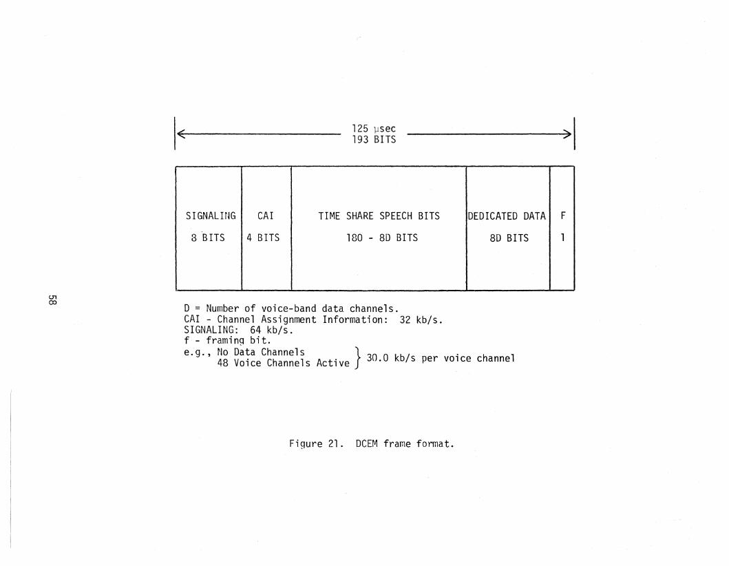
./~
125 lJsec193 BITS
.........-"
01()j
SIGNALING CAl TIME SHARE SPEECH BITS DEDICATED DATA F
3 BITS 4 BITS 180 - 8D BITS 80 BITS 1
o = Number of voice-band data channels.CAl - Channel Assignment Information: 32 kb/s.SIGNALING: 64 kb/s.f - framin9 bit.e.g., No Data Channels }. .
48 Voice Channels Active 30.0 kb/s per VOlce channel
Figure 21. DCEM frame format.

DCEC2 has developed a concept of five categories of interoperation, namely
channel interconnection,transmission interconnection,
group interconnection,
switched system interconnection, and
restoration capability.
The first three categories are differing approaches to digital pipeline interoperability while the fourth is end-to-end interoperability. The re1storation
capability is similar to the transmission interconnection except that the latter
is not necessarily bilateral.Figure 22 depicts DCS/TRI-TAC interoperability concepts discussed in the
draft CSC report (contract no. DCA-100-78-C-0053) for the digital channel level,
the group level, and the analog VF level that are closely related to DCEC·sfive
categories. Detailed information of the various DCS and TRI-TAC equipment shown
in Figure 22 may be found in Appendix A. The key to digital channel level interoperability is the FCC-100 (low-speed time division multiplexer - LSTDM). This
multiplexer has the capability of multiplexing low speed asynchronous or synchro
nous channels into group rates that are compatible with the FCC-99 multi rate (56,
64, 128, 256, 512 kb/s) synchronous input module. The 16/32 kb/s conditioneddiphase signal from the TRI-TAC LGM (loop group multiplexer) may be connected
into the FCC-100 as shown in Figure 22 (a). At the group level (Figure 22 (b))the TRI-TAC TGM (trunk group multiplexer) or the group modem have rates that are
compatible with the FCC-98 multirate synchronous input module. The purpose of
the group modem in this application is to convert from conditioned diphase to
non-return-to-zero (NRZ). The VF interface shown in Figure 22 (c) is self
explanatory.
5.2 Alternative A: New Intelligent FirstLevel Multiplexer
The first of the three alternatives for the pipeline level of interopera
bility is shown conceptually in Figure 23. The interface point for this alter
native is the first level multiplexer, which is a user-level interface as opposedto a group level interface. Because various types of user interfaces exist, both
voice and data, this alternative tends to be more complex than those described
2private £ommunications, J. Mensch, Defense Communications Engineering Center.
59
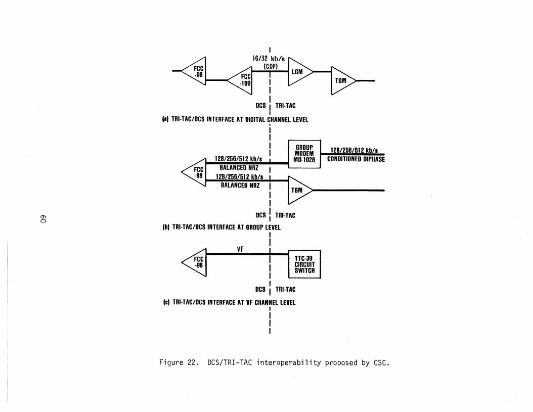
128/256/512 kb/lCONDITIONED DIPHASE
BALANCED NHZ I,I
DeS !TRI·TAC
(bl TRI-TAC/Des INTERFACE AT GROUP LEVELII
III
DCS I TRI-TACI
III TAI·TAC/DCS INTERFACE AT DIGITAL CHANNEL LEVELt
I,I I GROUPI MODEMI 128/256/512 kb/s , MO-l026
BALANCED HHZ128/256/512 kb/s
0)
a
TTC-3UCIRCUITSWITCH
YFIIII
DCS , rRI·TAC
lei Tnl·TAC/DCS INTERFACE AT VF CHANNEL LEVEL,III
Figure 22. DCS/TRI-TAC interoperability proposed by csc.
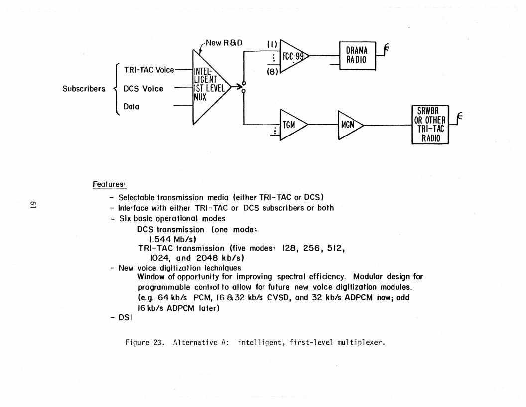
( I )
SRWBR~ OR OTHER
I TRI-TACRADIO
DRAMARADIO
TRI-TAe Voice
Data
Des VoiceSubscribers
())--J
Features:
- Selectable transmission' media (either TRI-TAe or DeS)- Inferface with either TRI-TAC or DeS subscribers or both- Six basic operafional modes
DeS transmission (one mode;1.544 Mb/s)
TRI-TAC transmission (five modes: 128, 256.512,1024, and 2048 kb/s)
- New voice digitization techniquesWindow of opportunity for improvi ng spectral efficiency. Modular design forprogrammable control to allow for future new voice digitization modules.(e.g. 64 kb/s peM. 16 a 32 kb/s CVSD, and 32 kb/s ADPCM now; odd16 kb/s ADPCM later)
- OSI
Figure 23. Alternative A: intelligent, first-level multiplexer.

in the suceeding sections. However, the interface at the user level provides a"window of opportunity" for using digital speech interpolation (DSI) techniquesalong with adaptive voice digitization to improve transmission efficiency, whileat the same time providing DCS/TRI-TAC interoperability.
As can be seen in Figure 23, not only will the new first-level multiplexerinterface simultaneously with both DCS and TRI-TAC subscribers on the channelside, but it will also interface with either the second level DCS multiplexer(FCC-99) or the second level TRI-TAC multiplexer (trunk group multiplexer - TGM)on the combined channel or group side. As shown, the combined channel interfaceis with the FCC-99 or the TGM, but not both simultaneously. The operationalscenario will dictate whether the transmission facilities beyond the new firstlevel multiplexer are tactical or DCS.
Figure 24 provides some elaboration on conceptual operational modes. Inparts (a) and (b) of the figure the traffic is assumed to be a mixture of bothDCS and TRI-TAC traffic. In part (a), tactical assets are used to provide transmission facilities between the new multiplexers at either end of the link. Thisis a capability that would satisfy both of the two following requirements:
(1) The use of tactical assets to provide temporary reconstitutionof a damaged DCS link, and
(2) the use of tactical assets to extend DCS coverage.
In part (b) of Figure 24, DCS assets are used to provide transmissionfacilities between the new multiplexers at either end of the link. This wouldsatisfy the requirement for the use of Des transmission facilities to interconnect two geographically separated tactical operational areas.
Parts (c) and (d) illustrate examples of the use of the new first-levelmultiplexer in DCS and TRI-TAC transparent modes. The point is' that the newmultiplexer should be capable of replacing the FCC-98 (DCS transparent example)or the LGM (TRI-TAC transparent example). Whether the new multiplexer wouldneed to be fully compatible with all operational modes (input and output datarates, number of channels, etc.) is an open question at this point. In thisreport, we wish merely to introduce examples of the potential utilization ofthe new first level intelligent multiplexer.
Table 9 provides examples of data rates for six basic operational modes.The basic operational modes correspond to six different output rates of thenew first-level multiplexer. One of the modes is DCS compatible and five are
62

(al MIXED DCS AND TRI·TAC TRAFFIC: TRI-TAC TRANSMISSION
DCS DCSSUBSCRIBERS .... SUBSCRIBERS
TRI-TAC TRI-TAC TOI-TAC THI-TACSUBSCRIBERS RADIO RADIO SUBSCRIBERSle.g. TRC-l101 fe.g. TRC-l101
(bl MIXED DCSANO TRI-TAC TRAFFIC: DCS TRANSMISSION
DCS ~DCSSUBSCRIBERS
"'"'SUBSCRIBERS
TRI-TAC DRAMA DRAMA K.FCClo ~TRI.TACSUBSCRIBERS RADIO RADIO 99 : SUBSCRIBERS
()) lei DCS TRANSPARENT IUSED IN PLACE OF AN FCC-gOIw
DCS ~ FCCI : DCSSUBSCRIBERS rA" .. D8· SUBSCRIBERS
DRAMA DRAMARADIO RADIO
l/"
(dl TRI-lAC TRANSPARENT (USED IN PLACE OF AN lGM)
Tnl-TAC ~
~LGMI: TRI·TACSUBSCRIBERS TRI-TAC TRI-TAC SUBSCRIBERS
RADIO RADIO,e.g. TRC·170) le.g. TRC·l10J
Figure 24. First-level intelligent multiplexer operational examples.

Table 9. ATternative A - Example Data Rates and Corresponding Number ofChannels for Intelligent First Level Multiplexer
First Level Mux Input Rates (kb/s)Mode Output Rates Comments
(kb/s) 16 32 64 128 256 512 1024
I. 1544 (DCS compatible)la. --- --- 24 --- --- --- ---- DCS transparent (voice)lb. --- --- --- --- --- 3 ---- DCS transparent (data)Ie. --- --- --- --- 6 --- ---- DCS transparent (data)Ide --- --- --- 12 --- --- ---- DCS transparent (data)Ie. --- --- 24 --- --- --- ---- DCS transparent (data)If. 90 --- --- --- --- --- ---- TRI-TAC only19· --- 45 --- --- --- --- ---- TRI-TAC onlylh. --- 20 12 --- --- --- ---- Possible combined DCS/TRI-TACI; . 40 --- 12 Possible combined DCS/TRI-TAC
II . 128 (TGM compatible)IIa. 8 --- --- --- --- --- ---- TRI-TAC transparent (7 VF channels)lIb. --- --- 2 --- --- --- ---- 2 64-kb/s PCM or data channelslIe. --- 2 1 --- --- --- ---- Combined DCS/TRI-TAC (1 IT TC)lId. 4 --- 1 --- --- --- ---- Combined DCS/TRI-TAC (3 TT TC)
III . 256 (TGM compatible)IlIa. 16 --- --- --- --- --- ---- TRI-TAC transparent (15 VF channels)IIIb. --- 8 --- --- --- --- ---- TRI-TAC transparent (7 VF channels)IIlc. --- --- 4 --- --- --- ---- 4 64-kb/s PCM or data channelsIIld. --- 4 2 --- --- --- ---- Combined DCS/TRI-TAC (3 TT Te)IIIe. 8 --- 2 --- --- --- ---- Combined DCS/TRI-TAC (7 n TC)IIlf. --- --- --- 2 --- ---- Data channel
IV. 512 (TGM compatible)IVa. --- ' 16 --- --- --- --- ---., TRI-TAC transparent (7 VF channels)IVb. 32 --- --- --- --- --- ----IVc. --- --- 8 --- --- --- ---- 8 64-kb/s PCM or data channelsIVd. --- 8 4 --- --- --- ---- Combined DCS/TRI-TAC (7 TT TC)IVe. 16 --- 4 --- --- --- ---- Combined DCS/TRI-TAC (15 IT TC)IVf. --- --- --- 4 --- --- ---- Data channelsIVg. --- --- --- --- 2 --- ---- Data channels
V. 1024 (TGM compatible)Va. --- --- --- 8 --- --- ---- TRI-TAC transparent (63 TT TC)Vb. --- --- --- 4 -_ ... ---- TRI-TAC transparent (31/59 TT TC)Ve. --- --- --- --- --- 2 -- .. - TRI-TAC transparent (31 TT TC)Yd. --- --- 16 --- --- --- ---- 16 64-kb/s PCM or data channelsVee --- --- --- 8 --- --- ---- Data channelsVf. --- --- --- --- 4 --- ---- Data channelsVg. --- --- --- --- --- 2 ---- Data channels
VI. 2048 (TGM compatible)VIa. --- --- --- 16 --- --- ---- TRI-TAC transparent (127 TT TC)Vlb. --- --- --- --- 8 --- ---- TRI-TAC transparent (63/127 TT TC)VIc. --- --- --- --- .....- 4 ---- TRI -TAC transparent (47 TT TC)VIde --- --- -_.- --- --- --- 2 TRI-TAC transparentVIe. --- --- 32 --- --- --- ---- 32 64-kb/s PCM or data channelsVlf. --- --- --- 16 --- --- ---- Data channelsVIg. --- --- --- --- 8 --- ---- Data channelsVlh. --- --- --- --- --- 4 ----- Data channels
Notes: I TT TC = TRI-TAC traffic channelsI Not all DCS or TRI-TAC modes are illustrated (e.g., other first level Des mux output bit
rates are 192, 384, and 768 kb/s).I Asynchronous data modules (O-20 kb/s and 50 kb/s modules in DeS) can replace the 64 kb/s
module 'on a one-for-one basis.
64

TRI-TAC compatible. The output rate for the DeS mode is 1.544 Mb/s which iscompatible with the FCC-99 multiplexer input. The output rates for the fiveTRI-TAC modes are compatible with the TGM multiplexer input. For each of thebasic modes, numerous combinations of voice and data channels could be accommoed. Some suggested combinations. are listed in Table 9 for the purpose of illustration. The exact input voice and data combinations that will be permissibleis an unresolved question at this time. For the purpose of introducing the newfirst-level multiplexer concept, it is not necessary to answer this question.
The example operational modes and inp~t data rates of Table 9 do not takeinto consideration the possible transmission efficiencies that could be achievedthrough the use of digital speech interpolation and adaptive speech digitization.Although efficient transmission utilization (or spectral efficiency) and DCSjTRI-TAC interoperability can be thought of as separate issues, the developmentof a new, intelligent first-level multiplexer provides a "window of opportunity"for addressing both issues simultaneously.
Voice encoding is currently achieved in the DCS in the FCC-98 first-levelmultiplexer. In the TRI-TAC system, voice encoding is performed at the subscriberinstrument. Voice encoding can also take place at the multiplexers or switches.In the new, intelligent first-'level multiplexer, there is an opportunity toachieve transmission efficiencies using a DSI/ADPCM concept similar to that employed in the Digital Channel Efficiency Model previously described.
There are several differences between the DCEM and the new intelligent,first-level multiplexer being considered here. The DCEM is not a multiplexer.Rather the DCEM performs compression, rate, and protocol conversion (interoperability) functions. The DeEM operates on one or more DS-l (1.544 Mb/s) or CEPTsignals (2.048 Mb/s). By contrast, the system being considered as alternativeII All performs multiplexing functions as well as compression functions. ~~hereas
the DCEM is capable of providing interoper~bility between the DCS and the PTTls(or the NATO Integrated Communication System), the new, intelligent first-levelmultiplexer would provide interoperability between the DCS and TRI-TAC. If theintelligent first-level multiplexer concept is accepted, interoperability betweenthe DCS and other networks such as NICS and ATACS should be considered as well.
One disadvantage of the approach used in the DeEM is that when heavy traf
fic conditions exist, conversion of the voice channel from PCM encoding to ADPCMmust take place. In the intelligent, first-level multiplexer there would be noneed for the PCM to ADPCM conversion. By assessing channel utilization prior to
65

digitization, the appropriate digitization technique (PCM or 7-3 bit ADPCM) canbe selected initially. If end-to-end digital encryption is employed, this advantage is negated.
Figure 25 is a functional block diagram of the intelligent first-levelmultiplexer. Note that this is the analog-to-digital conversion, data-input,and multiplexer portion only. The inverse functions of demultiplexing, digitalto-analog conversion, and data output are not shown. The basic concepts of theintelligent first level multiplexer can be described without providing the details of the inverse functions.
In Figure 25, TRI-TAC voice channels are assumed to be digitized at 16 or32 kb/s CVSD. The DSI/ADPCM technique will not be utilized on these channelsbecause they are already digitized at a comparatiVely low data rate. Whilehardware for converting from CVSD to PCM and vice versa has been developed(Zakanycz and Betts, 1978), it would be pointless to convert from CVSD to PCMto ADPCM just to accommodate traffic channel overloads when using DSI. As indicated in Figure 25 both digital data and CVSD encoded voice are sent to thedigital multiplexer. The CVSD channels first go through an activity detectorto determine if the channel is active, however.
The activity detectors for both the TRI-TAC CVSD digital channels and theDCS analog channels provide information to the microprocessor that provides theintelligence for this multiplexer. The microprocessor needs this channel activity information to determine the voice digitization technique (PCM or ADPCM) touse with the DCS anal,og channels, the number of bits to use if ADPCM encodingis required to avoid voice clipping for heavy channel utilization, the frameformatting employed by the digital multiplexer, and the channel assignment information which is transmitted to the new, intelligent first-level multiplexer atthe other end of the link. Techniques for voice activity detection have beenreported in the literature (see Drago et al., 1978, Kuhn et al., 1973, and Seitzet al., 1975, for example).
The voice/data detector is required because some of the input analog channels may be carrying voice-band data. Encoding such quasi-digital channelsusing ADPCM would likely cause unacceptably high bit-error rates (BER). Thevoice/data detector determines whether or not the channel is carrying voice-banddata and informs the control microprocessor of its decision. The control micro
processor uses this information to determine whether the channel may be encoded
66

TO T8M"RZ 128/258
512/1024/2048 kb/*
II'lIWEI _umy ~
+
IIIJI,1II . I
II I, .
I lL--- J --L -.J
V~
M-UAn
VtM-UAo
V~
M·LtADDes
AftAlOGTRUNKS
1i-20 kb/.
~ DIGITAL JASVFf.DATA
50 kb/.DATA ASVI
DATA
MULTI-RATESYNCDATA
lRHAC .rIB OR 32 khliDIGITAt CVSD
VOICE COP
Figure 25. First-level intelligent multiplexer functional block diagram(multiplexer portion only).
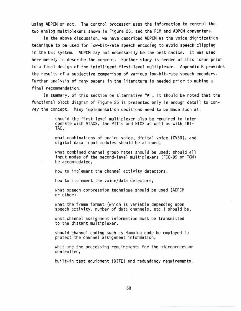
using AOPCM or not. The control processor uses the information to control thetwo analog multiplexers shown in Figure 25, and the PCM and ADPCM converters.
In the above discussion, we have described ADPCM as the voice digitizationtechnique to be used for low-bit-rate speech encoding to avoid speech clippingin the OSI system. AOPCM may not necessarily be the best choice. It was usedhere merely to describe the concept. Further study is needed of this issue priorto a final design of the intelligent first-level multiplexer. Appendix B providesthe results of a subjective comparison of various low-bit-rate speech encoders.Further analysis of many papers in the literature is needed prior to making afinal recommendation.
In summary, of this section on alternative IIA II, ,it should be noted that the
functional block diagram of Figure 25 is presented only in enough detail to convey the concept. Many implementation decisions need to be made such as:
should the first level multiplexer also be required to interoperate with ATACS, the PTT's and NICS as well as with TRITAC,
what combinations of analog voice, digital voice (CVSO), anddigital data input modules should be allowed,
what combined channel group rates should be used; should allinput modes of the second-level multiplexers (FCC-99 or TGM)be accommodated,
how to implement the channel activity detectors,
how to implement the voice/data detectors,
what speech compression technique should be used (ADPCMor other)
what the frame format (which is variable depending uponspeech activity, number of data channels, etc.) should be,
what channel assignment information must be transmittedto the distant multiplexer,
should channel coding such as Hamming code be employed toprotect the channel assignment information,
what are the processing requirements for the microprocessorcontroller,
built-in test equipment (BITE) and redundancy requirements.
68

how to interface with tech-control facilities in the DCSand TRI-TAC,
how to interface with encryption devices, and
how timing and synchronization problems arising from interfacing two plesiochronous systems are overcome.
All of the fundamental building blocks of the intelligent first level multiplexer have been previously investigated by other researchers. The activitydetectors and voice/data detectors are integral parts of any digital speech interpolation system. Using adaptive voice digitization to avoid speech clippingin DSI system has been under investigation by several organizations. As notedearlier, the DCEM uses the DSIjADPCM technique. Recent papers by Langenbucher(1982) and Yatsuzka (1982) also report on combined DSI/ADPCM systems. The intelligent, first-level multiplexer, although complex, does not require any advanced or basic research. All of the pieces have been developed previously byothers. The novelty in the intelligent first-level multiplexer lies in howthese pieces are put together to simultaneously address the DCS/TRI-TAC interoperability requirement along with the requirement for improved spectral efficiency.
5.3 Alternative B: Advanced Second-Level MultiplexerFigure 26 depicts the second alternative for the digital pipeline level of
interoperability between the Des and TRI-TAC. This alternative provides a DCS/TRI-TAC interface at the second multiplexer level. As shown in the figure, thenew second-level multiplexer will accommodate inputs from either the DeS firstlevel multiplexer (FCC-98), the TRI-TAC first level multiplexer (Loop GroupMultiplexer - LGM or Remote Multiplexer Combiner - RMC) or from a combinationof DCS and TRI-TAC first-level multiplexers. Depending upon the operationalmode selected, the combined bit stream is then fed into either the DRAMA radiofor transmission through DCS facilities or into a TRI-TAC radio for transmissionthr~ugh tactical facilities.
Table 10 provides an example of both input data rates (group rates) and output data rates (combined group rates). Seven operational modes are suggested inthe table. The seven modes are defined by the output (combined group) data rates.Four of the modes are DCS compatible, i.e., compatible with the DRAMA radio mission bit stream (MBS) whil'e three are compatible with TRI-TAC radios. Various
69
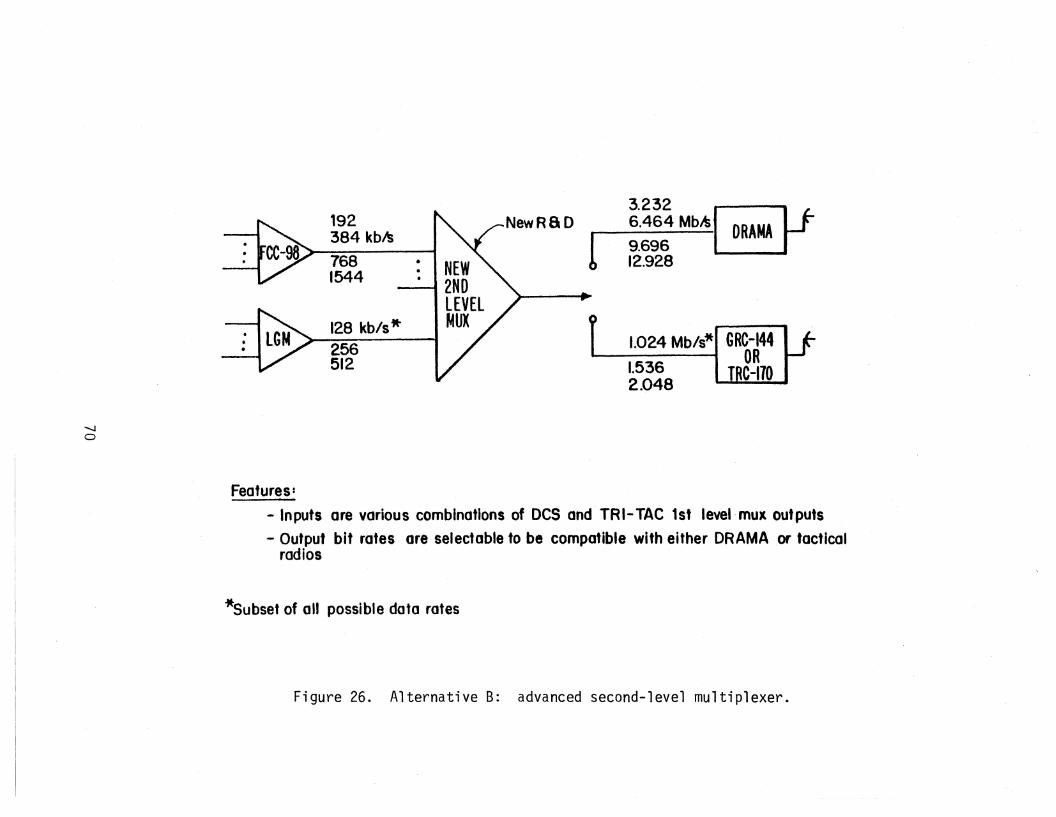
1.024 Mb/s* GRC-144OR
1.536 TRC-1702.048
3.232 ~New Ra0 6.464 MbltI DRAMA tI 9.696
12.928
192384 kbls
7681544
..-
: ILGN.> 128 kb/s*"256512
"-Jo
Features:
- Inputs are various combinations of DeS and TRI- TAe 1st level/mux outputs
- Output bit rates ore selectable to be compatible with either DRAMA or tacticalradios
*Subset of 011 possible data rates
Figure 26. Alternative B: advanced second-level multiplexer.

""""'-J....J
Table 10. Alternative B - Example Data Rates and Corresponding Number of Channels for NewSecond-Level Multiplexer
Second Level Multiplexer Input Data Rates (kb/s)Mode Output Data Rates Comments
(Mb/s) 128 256 512 1544
I. 3.232 (DCS compatible)Ia. --- --- --- 2 DCS transparentlb. --- --- 6 ---- TRI-TAC input; DCS transmissionIc. --- 12 --- ---- TRI-TAC input; DCS transmissionId. 24 --- --- ---- TRI-TAC input; DCS transmissionIe. --- --- 3 1 Combined TRI-TAC and DCS inputs; DCS transmission
I I . 6.464 (DCS compatible)IIa. --- --- --- 4 DCS transparentlIb. --- --- 12 TRI-TAC input; DCS transmissionIlc. --- 24 --- ---- TRI-TAC input; DCS transmissionlId. --- --- 3 3 Combined TRI-TAC and DCS inputs; DCS transmissionlie. --- --- 6 2 Combined TRI-TAC and DCS inputs; DCS transmissionIlf. --- 6 --- 3 Combined TRI-TAC and DCS inpqts; DCS transmissionIlg. 12 --- _._- 3 Combined TRI-TAC and DCS inputs; DCS transmission
III. 9.696 (DCS compatible)Ilia. --- --- --- 6 DCS transparentI I lb. --- --- 18 ---- TRI-TAC input; DCS transmissionIllc. --- --- 12 2 Combined TRI-TAC and DCS inputs; DCStransmissionIlld. --- --- 6 4 CombinedTRI-TAC and DCS inputs'; DCS tr,ansmissionIlle. --- 12 --- 4 Combi ned TRI -TAC and DCS inputs:; 'DCS transmi ss ionIllf . 24 --- --- 4 Combined TRI-TAC and DCS inputs; DCS transmission
IV. 12.928 (DCS compatible)IVa. _._- --- --- a DCS transparentIVb. --- --- 24 ---- TRI-TAC input; DCS transmissionIVc. --- --- 12 4 Combined TRI-TAC and DCS inputs; DCS transmissionIVd. --- 24 --- 4 Combined TRI-TAC and DCS inputs; DCS transmission
V. 1.024 (TRI-TAC compatible)Va. --- --- 2 ---- TRI-TAC transparentVb. --- 4 --- ---- TRI-TAC transparentVc. a --- --- ---- TRI-TAC transparent
VI. 1.536 (TRI-TAC compatible)Via. --- --- 3 ---- TRI-TAC transparentVlb. --- 6 --- ---- TRI-TAC transparentVic. 12 --- --- ---- TRI-TAC transparent
VII. 2.048 (TRI-TAC compatible)Vila. --- --- 4 ---- TRI-TAC transparentVllb" --- 8 --- ---- TRI-TAC transparentVile. 16 --- --- ---- TRI-TAC transparentVlld. --- --- --- 1 DCS input; TRI-TAC transmissionVile. --- 1 --- 1 Combined TRI-TAC and DCS inputs; TRI-TAC trans-
mission
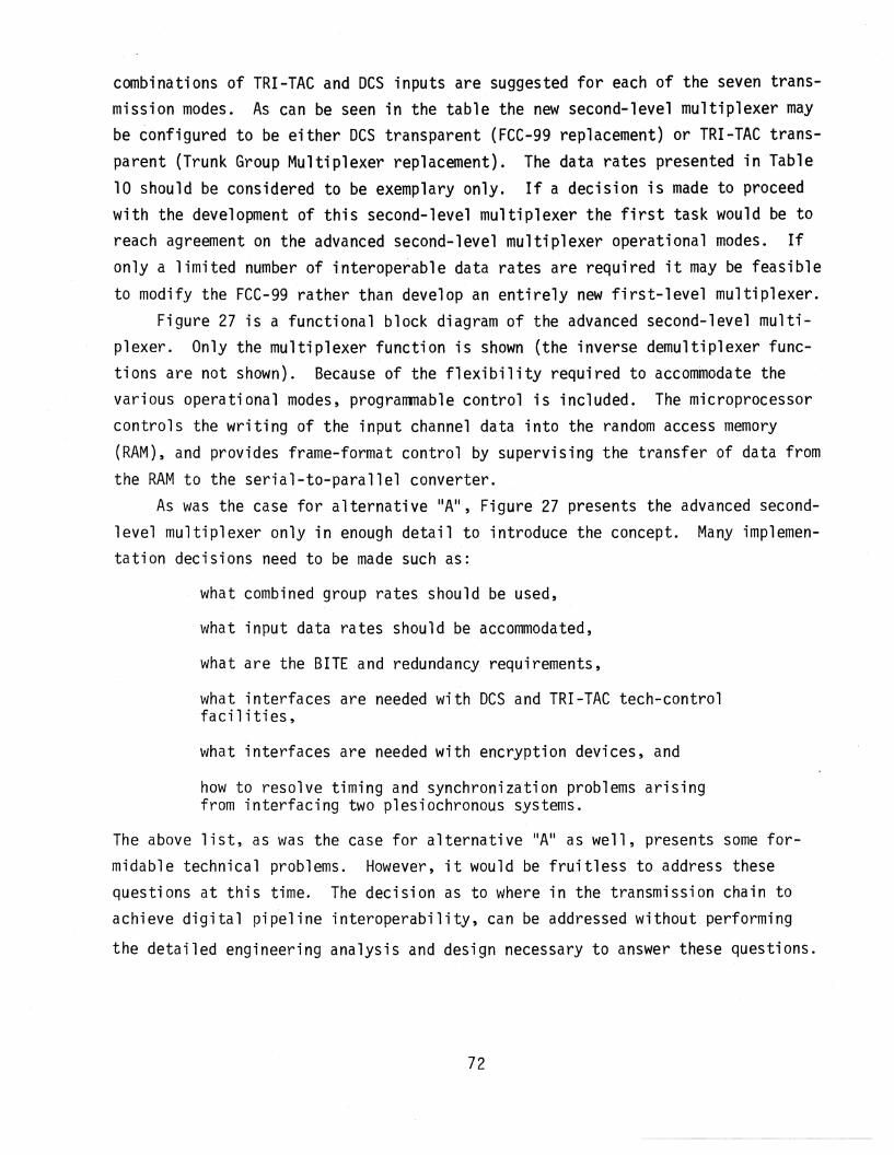
combinations of TRI-TAC and DCS inputs are suggested for each of the seven transmission modes. As can be seen in the table the new second-level multiplexer maybe configured to be either DCS transparent (FCC-99 replacement) or TRI-TAC transparent (Trunk Group Multiplexer replacement). The data rates presented in Table10 should be considered to be exemplary only. If a decision is made to proceedwith the development of this second-level multiplexer the first task would be toreach agreement on the advanced second-level multiplexer operational modes. Ifonly a limited number ofinterope~able data rates are required it may be feasibleto modify the FCC-99 rather than develop an entirely new first-level multiplexer.
Figure 27 is a functional block diagram of the advanced second-level multiplexer. Only the multiplexer function is shown (the inverse demultiplexer functions are not shown). Because of the flexibility required to accommodate thevarious operational modes, progranmable control is included. The microprocessorcontrols the writing of the input channel data into the random access memory(RAM), and provides frame-format control by supervising the transfer of data fromthe RAM to the serial-to-parallel converter.
As was the case for alternative IIA II , Figure 27 presents the advanced secondlevel multiplexer only in enough detail to introduce the concept. Many implementation decisions need to be made such qS:
what combined group rates should be used,
what input data rates should be accommodated,
what are the BITE and redundancy requirements,
what interfaces are needed with DCS and TRI-TAC tech-controlfacilities,
what interfaces are needed with encryption devices, and
how to resolve timing and synchronization problems arisingfrom interfacing two plesiochronous systems.
The above list, as was the case for alternative IIA II as well, presents some formidable technical problems. However, it would be fruitless to address thesequestions at this time. The decision as to where in the transmission chain toachieve digital pipeline interoperability, can be addressed without performing
the detailed engineering analysis and design necessary to answer these questions.
72

I ... loAUModules
TININGIr------.J
I· Data Bus
L_ -Llnput~elect Control __ ..,
INPUT• PORT
#1
fL_-
lI
INPUTIIPORT I#2 II
~.
I CombinedIL---i ELASTIC STORE SERIAL TO PARAlLEL Bit Stream
I (RAN) ~ CONVERTER to Rc.I.I
~IINPUT I
I
PORT I IFrame#24 I f ••
I f="ormat
I tIControl
f- a I I
InputChannels
.........w
r-I
MICROPROCESSOR ..., RONCONTROLLER ~
L I
I.
External Clock
Mode and Rato _ _ _ _ _ --JSelection by Operator
Figure 27. Advanced second-level multiplexer concept.
5.4 Alternative C: Digital Radio InterfaceThe DRAMA radio includes an internal mUltiplexer which might be considered
to be the third-level mUltiplexer in the DeS multiplex hierarchy. The functionof this multiplexer is to combine two mission bit streams from the FCC-99 secondlevel multiplexer into an aggregate bit stream (ABS) which ;s fed to the modemof the DRAMA radio (see Appendix A for details on DRAMA). Conceptually the DRAMAradio multiplexer could be modified to accommodate TRI-TAC mission bit streamsfrom the TRI-TAC Trunk Group Multiplexer (TGM) as well as from the DCS FCC-99second-level multiplexer. This is shown conceptually in Figure 28.
Table 11 provides some example aggregate bit stream data rates for variouscombinations of TRI-TAC and DCS mission bit streams. The table is exemplary only.Other combinations are feasible. Only the MBS and ABS that are specified as partof the DCS reconstitution radio have been included in Table 11. The DRAMA MBSrates of 3.232 and 9.696 Mb/s and ABS rates of 9.952 and 19.648 have not beenincluded. Also not included are the TRI-TAC mission bit stream rates of 9.36
and 18.72 Mb/s, which are available from the Master Group Multiplexer (MGM).Note that Alternative C bears a strong resemblance to the proposed recon
stitution radio which also has a programmable multiplexer which can accommodatea variety of mission bit stream data rates.
5.5 Evaluation of Alternatives for DigitalPipeline Interoperability
Having introduced several alternatives for achieving the digital pipelinelevel of interoperability, it is now appropriate to subjectively compare thevarious approaches for pipeline interoperability. Table 12 summarizes the concepts that were introduced in Sections 5.1 through 5.4. The Digital ChannelEfficiency Model is included in Table 12 because the DSI/ADPCM technology usedin the DCEM to simultaneously provide spectral efficie'ncy and interoperabilitybetween the DeS and the PTTls could be adapted to the DCS/TRI-TAC interoperability problem.
The approach currently being pursued jointly by the TRI-TAC program officeand DCA does not address the requirement for transmission from DCS through TRITAC to a DCS destination. 3 This approach is therefore not responsive to JCS andDCA requirements as summarized in Section 4.
3private communications, Johann Holzer, Joint Tactical Communications Office,Ft. Monmouth, New Jersey'.
74

RADIOI I FREQUENCY
UNIT• QPR.• QPSK•OTHER?
RECONFIGURA BLEMODEMMUX/DEMUX
PROGRAMMABLE- I
3RD LEVEL IIIII
I~ I ." "L __I ~
r--------------------~
I I I I I I I IIIII
1.0241.536 Mb/s*
2.048
3.2326.464 Mb/s
9.69612.928
'.JCJ1
192 kb/s **
*Subset ofTGM multiplexer andTRC-170 and GRC-144 radios
**Service Channel Bit Stream ;...SCBS
Features:
- Possibly new modulation technique (e.g. 64-QAM)
- Modulation could be changed depending upon multipath fading, jamming, etc.
- Transparent modes
- DCS
- TRI-TAC
- Adoptive equalization
Figure 28. Alternative C: modified DRAMA radio.

..........
""'
Table 11. Alternative C - Example Data Rates for Modified DRAMA Radio
Mission Bit Stream (MBS)Mode Aggregate Bit Stream (ABS) Data Rates (Mb/s) ConmentsData Rate (Mb/s)
6.464 12.928 1.024 1.536 2.048
I . 6.720la. 1 --- --- --- --- Des transparentlb. --- --- 6 --- --- TRI-TAC input; DCS transmissionIc. --- --- --- 4 --- TRI-TAC input; DeS transmissionId. --- --- --- --- 3 TRI-TACinput; DeS transmission
I I. 13. 184IIa. 2 --- --- --- --- DCS transparentlIb. --- 1 --- --- --- DCS transparentIIc. 1 --- 6 --- --- Combined DeS and TRI-TAe inputs; DeS transmissionlId. 1 --- --- 4 Combined DCS and TRI-TAC inputs; DeS transmissionlIe. 1 --- --- --- 3 Combined DCS and TRI-lAe inputs; DeS transmissionIIf. --- --- --- --- 6 TRI-TAC input; DCS transmission
III. 26.112IlIa. --- 2 --- --- --- DCS transparentIllb. 1 --- 18 --- --- Combined DeS and TRI-TAe inputs; DeS transmissionIllc. --- 1 12 --- --- Combined DeS and TRI-TAe inputs; DeS transmissionIlId. --- 1 --- --- 12 Combined DeS and TRI-TAC. inputs; Des transmissionIIIe. --- --- 24 TRI-TAC input; DeS transmission
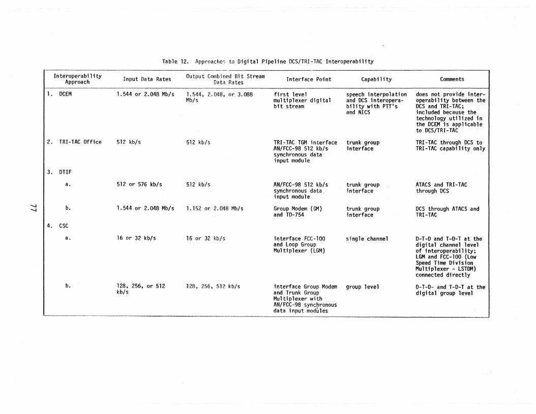
Table 12. Approaches to Digital Pipeline DCS/TRI-TAC Interoperabi1ity
.........
.........
lnteroperabi 1i tyApproach
1. DCEM
2.TRI-TAC Office
3. DTIF
a.
b.
4. CSC
Input Data Rates
1.544 or 2.048 Mb/s
512 kb/s
512 or 576 kb/s
1.544 or 2.048 Mb/s
Output Combined£it StreamData Rates
1.544, 2.048, or 3.088Mb/s
512 kb/s
512 kb/s
1.152 or 2.048 Mb/s
Interface Point
first levelmultiplexer digitalbit stream
TRI-TAC TGM interfaceAN/FCC-98 512 kb/ssynchronous datainput module
AN/FCC-98 512 kb/ssynchronous data.input module
Group Modem(GM)and TO-754
Capabi 1ity
speech interpolationand DCS interoperabi1ity with PTTISand NICS
trunk groupinterface
trunk groupinterface
trunk groupinterface
Comments
does not provide interoperability between theDCS and TRI-TAC;included because thetechnology utilized inthe DCEM is applicableto DCS/TRI-TAC
TRI-TAC through DeS toTRI-TAC capability only
ATACS ·and TRI-TACthrough DCS
DCS through ATACS andTRI-TAC
a.
b.
16 or 32 kb/s
128, 256, or 512kb/s
16 or 32 kb/s
~28, 256, 512 kb/s
i~terface FCC-100 single channeland loop GroupMultiplexer (LGM)
interface Group Modem group leveland Trunk GroupMultiplexer withAN/FCC-98 synchronousdata input modules
D-T-O and T-D-T at thedigital channel levelof interoperability;LGM and FCC-100 (LowSpeed Time DivisionMultiplexer - LSTDM)connected directly
O-T-O- and T-D-T at thedigttal group level

Table 12. (continued)
Interoperabi 1i tyApproach
5. AlternativesDescribed inthis Report
a.
Input Data Rates
16, 32, 64, 128,256, 512, and1,024 kb/s
Output Combined Bit StreamData Rates
128, 256, 512, 1,0241,544, and 2,048 kb/s
Interface Point
first levelmultiplexer
Capabi 1i ty
user levelinterface
Comments
provides both 0-1-0 and1-0-1 interoperability;provides spectralefficiency through theuse of OSI/ADPCM
128, 256, 512, and1,544 kb/s
-......,JCO
b.
c.
1.024, 1.536, 2.048,3.232, 6.565, 9.696,12.928 Mb/s
1.024, 1.536, 2.048, 6.720, 13.184, and6.464, and .12.928 26. 112 Mb/sMb/s
second levelmultiplexer
third levelmultiplexerinternal toDRAMA radio
group· levelinterface
highest levelinterface
provides both 0-1-D and1-0-1 interoperability
1-0-1 capability only

The approaches of the DTIF and that of CSC to DCS/TRI-TAC inter'operabi1ityare respons i ve to both the DCS-through TRI -TAC to DCS (0-T-0) requi r'ement as we11as its inverse (T-D-T). However, theDTIF does not address the spectral efficiency issue which is addressed by Alternative A described earlier in this report.The DTIF appears to be an expensive approach because of the inclusion of the DACSwhich is not needed for interoperabi1ity. As noted in the study by ComputerSciences Corporation (CSC, 1982), the use of the DACS (or its military equivalentthe Digital Patch and Access System - DPAS) may be an overkill for many DCS nodalrequirements. The DACS can handle up to 1,524 through connected PCM channels(64 kb/s 05-0 signals). Its use may not be economically attractive in many DCSnodal applications. The use of the DACS in the DTIF does not appear warrantedfor interoperability purposes. Several of the studies such as the DTIF effortand the CSC study were made known to ITS nnly after the ITS study was nearlycomplete.
A subjective evaluation of the three alternatives is provided in the following paragraphs. This evaluation must necessarily be subjective because, as notedin Section 4, the DCS/tactical interoperability requirements are stated only invery general terms. Even these general requirements are not universally agreedupon. Without firmly established and agreed upon general requirements (such asthe level of interoperability needed) it is obviously difficult to establishspecific requirements (such as the number of DCS voice channels that interoperableTRI-TAC equipment should be designed to handle). Without these spec'ific requirements a quantitative evaluation of alternatives is not possible. Therefore thealternative evaluation in the following paragraphs must necessarily be subjective.
The following evaluation factors will be used in comparing the alternativesfor DCS/TRI-TAC interoperability:
performance,operational flexibility,complexity and risk, andcost.
Performance
It is· difficult to generate a quantifiable performance measure because the
interoperability requirements are not specific. The identification of a viableperformance measure is made more difficult because the three alternatives areat three different points in the transmission chain. One cannot compare the
79

performance of a first level multiplexer with the performance of a second-levelmultiplexer. One performance measure that is common to all three multiplexerlevels and which could be used for comparison purposes might be spectral efficiency. However only Alternative A addresses the spectral efficiency questionor its equivalent, efficient source digitization. Alternative A (intelligentfirst-level multiplexer) is responsive to the spectral efficiency requirement aswell as the interoperability requirement. Up to 4:1 compression has been reported(Langenbucher, 1982) for systems using a combined DSI/ADPCM approach. A 4:1 com-pression was demonstrated by Kuhn et al., (1973) using DSI with a variable numberof quantizing bits for PCM. Depending upon the number of active TRI-TAC voicechannels and number of data channels, both of which will not be compressed usingADPCM, it might be expected that a 2:1 efficiency improvement might be achievedin the intelligent first level multiplexer.Operational Flexibility
Alternatives A and B are responsive to the requirement for both DCS throughTRI-TAC to DCS (D-T-D) and TRI-TAC through DCS to TRI-TAC (T-D-T). AlternativeC meets only the T-D-T requirement. Alternatives A and B have both DCS and TRITAC transparent modes, combined traffic modes, modes in which TRI-TAC transmission equipment is used to carry only DCS traffic (reconstitution case), and modesin which DCS transmission equipment is used to carry only TRI-TAC traffic. Alternative C does not provide for TRI-TAC RF transmission.
When considering the problem of reconstitution of the Digital European Backbone (DEB) using tactical assets, the highest level of transmission interoperability is desirable. Highest level of transmission interoperability refers tothe highest multiplexer level. To illustrate this consider Figure 29 whichdepicts three typical DEB nodes. Suppose that node B has been made inoperationalby some natural disaster, sabotage, etc. To achieve connectivity from node A tonode C using tactical assets, interoperability must exist between the DCS andtactical equipment at some point in the first-level multiplexer, second-levelmultiplexer or radio transmission chain. If the point of interoperability isat the user-level (first level) multiplexer, more tactical equipment is requiredthan if the point of interoperability is further along in the transmission chain.Therefore from the standpoint of operational considerations, the third-level
multiplexer interface, which is internal to the modified DRAMA radio (Alternative
C), is the most desirable of the three alternatives.
80
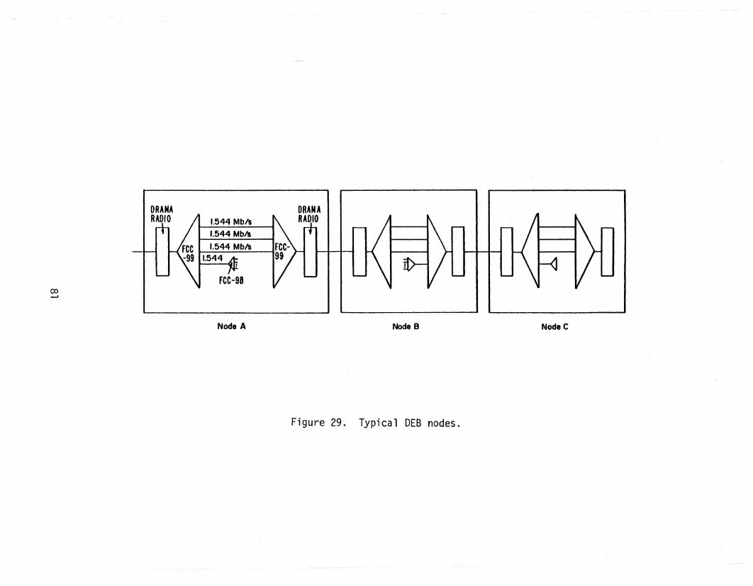
co......
Node A Node B
Figure 29. Typical DEB nodes.
NodeC

Complexity and RiskAlternative A (intelligent first-level multiplexer) is the most complex of
the three alternatives. However, no technological breakthroughs are required.As noted earlier all of the technical concepts have been previously provenalthough not in the configuration that has been suggested in Alternative A.Cost
There are two parts to the cost question. The first is the development costwhile the second is the operational and maintenance (O&M) costs. Together theyconstitute the total life-cycle cost (LCC). The development cost is directlyrelated to complexity. Therefore the development cost of Alternative A wouldlikely exceed the development costs for any of the other alternatives. Estima
tion of O&M costs is clearly beyond the scope of this study. Note, however, thatif the requirement to interoperate with the PTT's is added to the requirement tointeroperate with TRI-TAC, operational costs for the Alternative A are likely tobe greatly reduced because of the use of DSI/ADPCM technology. The tradeoff isbetween reduced operational costs and high development costs.Recommendation
It is recommended that CSA pursue Alternative A, the intelligent first-levelmultiplexer, and possibly Band C as well. Despite the higher development costsof Alternative A compared to Band C, the added benefit of speech compressionappears to outweigh the added complexity. Frequency assignments in Europe canbe expected to become increasingly difficult to obtain. Therefore efficientspectrum utilization becomes as important an issue as the interoperability issue.The intelligent first-level multiplexer addresses both of these issues.
The importance of the spectral efficiency issue is evident by the DCS RDT&EPlan 1983-1989 (DCEC TR 2-82). One of the eight system attributes of the unifiedDCS/DSN RDT&E program is efficient spectrum utilization. The threads for achieving this include:
(1) exploitation of higher electromagnetic frequencies,
(2) efficient use of transmission bandwidth,
(3) improved source coding,
(4) data and voice resource sharing, and
(5) diverse common resources through interoperability.
The Alternative A concept is responsive to items (2) through (5).
82

Section 7 contains a suggested series of tasks that need to be undertaken inthe development of a new 'intelligent first-level multiplexer. It is worthwhilementioning the first task at this point, however. The first task would be todetermine the operational modes (mission bit stream and aggregate bit stream datarates). In this report, we have addressed only DCS/TRI-TAC interoperability.Prior to development of the suggested new first-level multiplexer, a decisionshould be made as to whether the concept should be expanded to include interoperability with ATACS and the PTTIS (or NICS) as well. If interoperability withthe PTTls is included, then the spectral-efficiency issue takes on even greaterimportance. Several of the PTTls are in the process of making fundalnental changesin their tariff structures. Rather than tariffs that are based on a flat rate fora specified distance, the tariffs will be volume or usage dependent. Therefore,the spectral efficiency that may be attained using the DSI/ADPCM concept of Alternative A is a very desirable attribute.
6. END-TO-END DIGITAL INTEROPERABILITYAs noted in Section 4, a limited end-to-end TRI-TAC capability for inter
operation with AUTOVON is currently being planned using a VF analog interfaceand SF (single frequency) signaling. However, the predominate DCS network inEurope in the late 1980 ls and beyond will be the European Telephone System. Itis expected that the ETS and AUTOVON will eventually merge and become the European portion of the DCS or its successor the Defense Switched Network - DSN. TheETS will be primarily a d-igital network using primarily digital trunking andhybrid switches (switching is digital, but both line and trunk interfaces may.beeither analog or digital). Interswitch signaling will be based upon the CCITT#7 common channel signaling (CCS) system. By way of contrast, TRI-TAC uses anentirely different set of digital transmission parameters, different hybridswitches, its own version of common channel signaling, and a system control(SYSCON) hierarchy entirely independent from that of the DCS. These differencesmake full end-to-end interoperability between the ETS and TRI-TAC on the digitallevel difficult to achieve.
As noted in Section 3, the report on the DCS RDT&E Program for FY 1983/1989
(DCEC TR 2-82) states that one of the thrusts for integrated design and systemcontrol is to ,develop interoperation between the DCS control subsystem and thatof tactical systems. The WWDSA transition plan (DCA report published in 1982)
83

describes the deficiencies of the DCS. One such deficiency listed is the poorinteroperability be.tween the DCS and TRI-TAC except at VF. These documents validate the requirement to conduct RDT&E programs aimed at achieving end-to-enddigital interoperability between TRI-TAC and the DCS.
Table 4 listed the major parameters or system characteristics that must beinvestigated to achieve full end-to-end interoperability. A complete investigation of all of these parameters is beyond the scope of this report. The following two sections contain discussions of two of these parameters, namely, signaling and system control. An entire'report could (and should) be written on eachof these two aspects of the full end-to-end interoperability problem. An overview of these two topics is appropriate here because the U.S. Army has majorresponsibilities for switches, both for the ETS switch used in West Germany, andfor the TTC-39 switches used in TRI-TAC. Signaling, of course, is a function ofswi tches.
Both the U.S. Air Force and the U.S. Army have some responsibilities forDCS/tactical system control (SYSCON) interoperability. The U.S. Army has responsibility for the development ofa Military Function Controller that will providefor interoperation between control elements of theDCS and those of the commoncarriers, tactical and allied systems in order to support rapid reconstitutionand restoration of the DCS (see DCEC TR 2-82 for a description of the MFC program) .
The discussions on signaling and system control will be followed by a briefdiscussion on voice digitization conversion. The section is concluded with theintroduction of some approaches to end-to-end interoperability. It would be premature to attempt a full discussion of alternatives, and evaluation of thesealternatives. Other, more detailed, analyses of specific requirements must beaccomplished before such alternative definition and evaluation can be realistically accomplished. A list of suggested tasks for achieving these objectives willbe presented in Section 7. The end-to-end interoperability concept in generaland in particular the interoperability of signaling systems and SYSCON systemsare desirable long-term goals for military communications networks. The following sections on signaling and system control will provide some insight on thecomplexity of the issue and for the need for more detailed analyses.
84

6.1 Interoperabi1ity' Between ETS and TRI-TAC Signaling SystemsThe discussion on the signaling aspects of DCS/tactical interoperability
will be limited to ETS (since it is expected to be the major element of the DCSin Europe in the late 1980's and beyond) and to the TRI-TAC TTC-39 switch thatuses CCS for interswitch signaling. There are other smaller unit level switchesthat are part of TRI-TAC as well as other tactical switches (existing inventory)that interface with TRI-TAC. These other switches do not use CCS. The signaling interface between tactical systems and the ETS is most likely to occur inthe TTC-39 switch. Therefore, only the TRI-TAC CCS signaling will be discussedeven though other signaling techniques are also used in TRI-TAC (for exampledigital in-band signaling is used for signaling between parent switches and subordinate switches [TRI-TAC, 1982f]).
The ETS will utilize common channel signaling based upon CCITT SignalingSystem #7 (DCA, 1981a): However, the military may develop its own signalingsystem by modifying CCITT #7 in order to meet unique military signaling requirements (DCEC, 1981). The proposed modifications to CCITT #7 for supportingunique Defense Switched Network features include support for:
multilevel precedence and preemption (MLPP),community of interest screening,protected hotline,automatic off-net interconnect,inward off-net accesszone restrictions,call forwarding,operator call,satellite link limiting control,protocol and rate checks~
conferencing, andSYSCON.
If in fact, eeITT #7 is modified to meet DSN (including ETS) requirements~ thelist of modifications should include changes needed to make ETS signaling compatible with the TRI-TAC common channel signaling. Possibly the unique militaryrequirements could be met by using the user portion of the eCITT #7 format.
One of the differences between eCITT #7 and the TRI-TAC ecs is that the latter is associative while the former may be either associative or nonassociative.
85

Figure 30 illustrates a typical TRI-TAC switching configuration for a call.Because the TRI-TAC CCS is associative, the signaling messages are relayed fromswitch to switch along the same path that the information message (digitizedvoice) follows.
The associative concept is further illustrated in Figure 31 where signalingmessages are shown to be relayed. Fi.gure 31 also illustrates another differencebetween CCITT #7 and theTRI-TAC CCS. Each signaling message in the latter systemis acknowledged by the receiving switch. Acknowledgment messages are sent byeach intermediate switch as well as the origination and destination switches. Byway of contrast, the CCITT Signaling System #7 does not use acknowledgment signaling messages.
Table 13 provides a partial list of TRI-TAC trunk signaling messages. Certain other signaling messages that deal with satellite link control and communications security are not included because their formats are classified. Furtherinformation on these messages may be found in the TRI-TAC CCS specification.Inclusion of these messages is not pertinent to the current discussion becausethey would not be utilized betweenTRI-TAC and DCS. These messages are usefulonly internally to TRI-TAC (DCEC, 1981).
Table 14 provides a comparison between the TRI-TAC CCS messages previouslygiven in Table 13 and the CCITT #7 equivalent. This table, which was preparedby a contractor for the Defense Communications Engineering Center (DCEC), is afirst step in addressing the TRI-TAC CCS/CCITT #7 interoperability question.However, much additional work remains. As noted in the table there are nineTRI-TAC messages that have no CCITT equivalent. Note, however, that seven ofthese messages are useful only to TRI-TAC, i.e., there is no need for the message to cross the interface.
The messages in Table 14 that indicate equivalency are only roughly equivalent functionally. Obviously, any common channel signaling system must have sometype of call initiation message. As shown in the top line of Table 14, both theTRI-TAC CCS and the CCITT have a functionally equivalent call initiation message.The content of the functionally equivalent messages listed in Table 14 differssignificantly in some cases. A full field-by-field comparison of these functionally equivalent messages is beyond the scope of this report. This is a necessary(and complicated) next task. Before this task can proceed, however, it would bedesirable to have a firmly established CeITT #7 that has been modified for military applications.
86

Q00'.J
~ TTC-39 TTC-39 TTC-39SWITCH A SWITCH B SWITCH B
~
CALLINGPARTY
ORIGINATINGSWITCH
TANDEMS\1JITCH
TERMINATINGSWITCH
CALLEDPARTY
Figure 30. Typical TRI-TAC switching configuration for a call.

0000
TTC-39SWITCH A
CALL INITIATE >< ACK
CALL INITIATE ..........
ACK.",
(
< CALL COMPLETEACK "-
CALL COMPLETE "<
ACK :> TTC-39SWITCH B <: CALL ANSWER
ACK "-
CALL ANSWER/
<ACK >
CALL RELEASE :>./ ACK" CALL RELEASE ;>
< ACK
TTC-39SWITCH C
Figure 31. Typical TRI-TAC signaling generated by call setup/teardown.
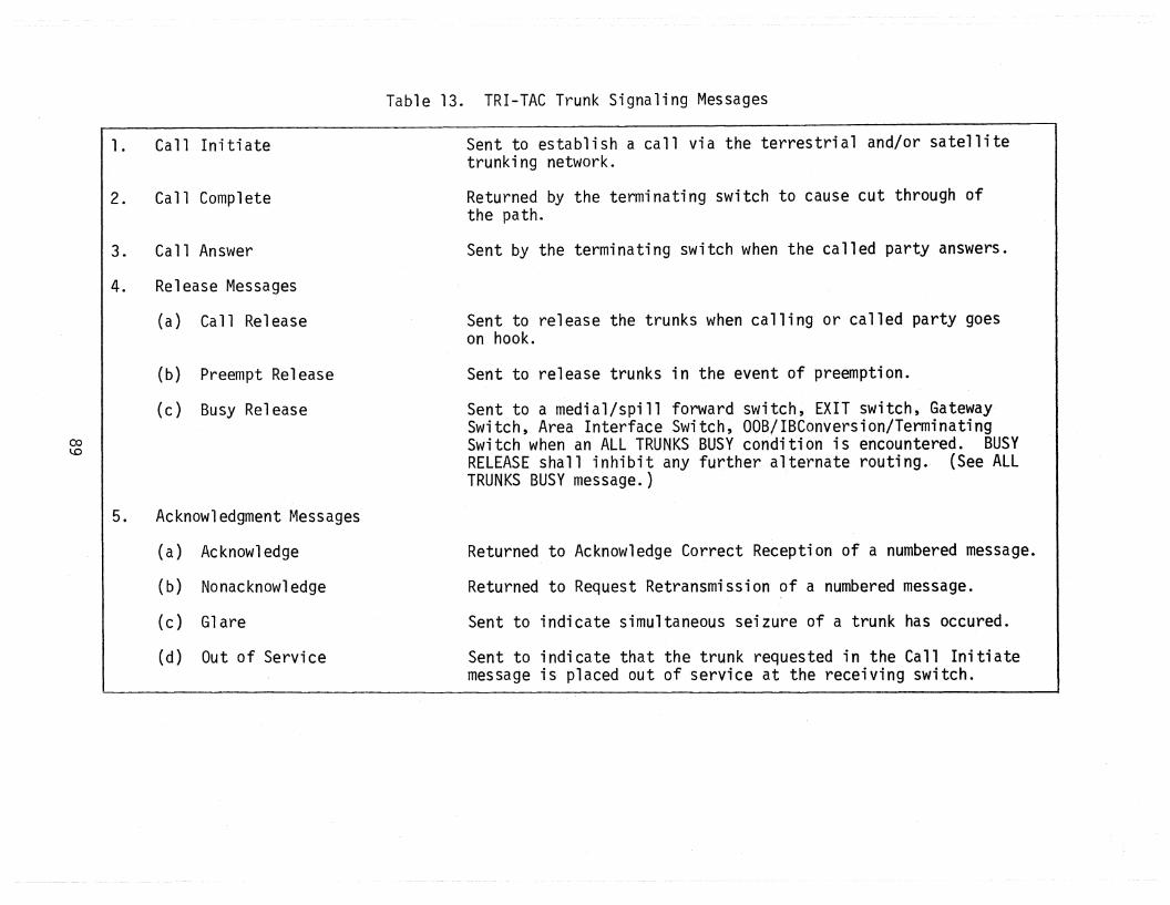
1• Call Initiate
2. Call Complete
3. Call Answer
4. Release Messages
(a) Call Release
(b) Preempt Release
(c) Busy ReleaseI
0:>~
Table 13. TRI-TAC Trunk Signaling Messages
Sent to establish a call via the terrestrial and/or satellitetrunking network.
Returned by the terminating switch to cause cut through ofthe path.
Sent by the terminating switch when the called party answers.
Sent to release the trunks when calling or called party goeson hook.
Sent to release trunks in the event of preemption.
Sent to a medial/spill forward switch, EXIT switch, GatewaySwitch, Area Interface Switch, OOB/IBConversion/TerminatingSwitch when an ALL TRUNKS BUSY condition is encountered. BUSYRELEASE shall inhibit any further alternate routing. (See ALLTRUNKS BUSY message.)
5. Acknowledgment Messages
(a) Acknowledge Returned
(b) Nonacknowledge Returned
(c) Glare Sent to
(d) Out of Servi ce Sent tomessage
to Acknowledge Correct Reception of a numbered message.
to Request Retransmission of a numbered message.
indicate simultaneous seizure of a trunk has occured.
indicate that the trunk requested in the Call Initiateis placed out of service at the receiving switch.

\.0a
6. Call Incomplete Messages
(a) Called Party Unavailable
(b) All Trunks Busy
(c) Unassigned Loop
(d) Incompatible Connection
(e) Invalid Route
7. Synchronization Message TestSync
8. Trunk Test Messages
(a) Loop Back Trunk
(b) Loop Back Complete
Table 13. (continued)
Returned to indicate that the called party or trunk is busy ona call of equal or higher precedence.
Returned by a medial switch when it encounters the ALL TRUNKSBUSY condition or if the equipment necessary to complete thecall is unavailable. This message is not used by other typesof switches (e.g., EXIT, GATEWAY, etc.). These switches returnBUSY RELEASE instead. (See BUSY RELEASE message.)
Returned to indicate that the called number is not assigned.
Returned to indicate that the called terminal is not compatiblewith the calling terminal.
Returned by a switch which cannot continue to route a callbecause of insufficient entries in the routing table.
Sent to verify interswitch signaling channel synchronization.
Sent to have a trunk looped back on itself for testing purposes.
Confirmation that loop back is completed.

Table 14. Equivalency Between TRI-TAC and CCITT No.7 Signaling Messages
\..0--'
TRI-TAC Message
Ca 11 In i t i ate
Call Complete
Ca 11 Ans\'tJer
Call Release
Preempt Release
Busy Release
Acknowledge*
Nonacknowledge*
Glare*
Out of Service*
StandardCCITT No. 7 Equivalent
Initial Address Message
Address Complete
Answer
Clear Forward
None
Congestion
None
None
None
None
Comments
Also Initial Address with Additional Information
Depending on Call Direction, #7 may first sendClear Back, then Clear Forward or just ClearForward only.
Adapted #7 will have Preempt~ Preempt in Progress,and Preempt Complete- messages.
Causes #7 to generate Clear message to releasetrunks.
In #7 Acknowledgments are contained in the Backward Sequence Number. Not an internetwork function. Will not cross interface.
Retransmission in #7 requested by Inverting Backward Indicator Bit. But not an internetwork function. Will not cross interfaces.
Adjacent switches detect glare in both networks.Not an internetwork function. Will not crossinterface.
Refers to adjacent switch trunks. Not an internetwork function. Will not cross interfaces.
*Message will not cross interface.

TRI-TAC Message
Called PartyUnavailable
Table 14. (continued)
StandardCCITT No. 7 Equivalent
Subscriber Busy
Comments
\DN
All Trunks Busy
Unassigned Loop
IncompatibleConnection
Invalid Route
Congestion(See Comments)
Unallocated NationalNumber
None
Call Failure
No. #7 signaling generated unless TRI-TAC hasexhausted all alternate routes, then TRI-TACsends Busy Release, + #7 sends congestion + clear.
Adapted CCITT #7 will include Protocol, RateChecks and Terminal Parameter Incompatibilitymessage.
Test Sync* None
Loop Back Trunk* None
Loop Back Complete* None
*Message will not cross interface.
Checks Link Synchronization. Not an internetworkfunction. Will not cross interface.
#7 has messages for continuity checking on a percall basis. TRI-TAC routinely tests individualtrunks. Not an internetwork function. Will notcross interface.
#7 has messages for continuity checking on a percall basis. TRI-TAC routinely tests individualtrunks. Not an internetwork function. Will notcross interface.

Table 14 is only a one-way comparison of TRI-TAC CCS and CCITT #7, i.e., itshows all of the pertinent TRI-TAC messages, and their CCITT functional equivalent. It does not show all of the 35 cCln messages. However, eleven of theCCITT messages have no usefulness outside of the CCITT system', i.e. ,there is noneed for them to cross the CCITT/TRI-TAC signaling systems boundaries.
Figure 32 depicts the gene~ral CCITT #7 and TRI-TAC CCS signaling formats.These formats are the same for each of the 18 TRI-TAC signaling messages and the35 CCITT #7 signaling messages. A meaningful comparison can be made only by looking at specific messages such as the call initiate messages.
In summary of the discussion on signaling the following differences betweenCCITT #7 and the TRI~TAC CCS have be~n noted:
1) TRI-TAC acknowledges the receipt of each message; CCITT doesnot,
2) TRI-TAC is associative CCS and has either a 16 kb/s or 32 kb/sdigital signaling channel ot a 1.2 or 2.4 kb/s analog (quasidigital) signaling channel; CCITT #7 may be either associativeornonassociative and can accommodate data rates up to 64 kb/s,
3) there are 18 unclassified message types in TRI-TAC CCS; CCITThas 35 message types,
4) there are TRI-TAC message types that have no functional equivalentin CCITT #7 and vice versa,
5) message types that are generally functionally equivalent in thetwo signaling systems may differ significantly in the actualcontent of the message fields,
6) CCITT #7 does not accommodate some required military functionssuch as MlPP that TRI-TAC does perform; however CCITT #7 maybe adapted to handle these functions.
6.2 Interoperability Between ETS and TRI-TAC SYSCON FacilitiesFigure 33 depicts the DCS system control hierarchy (Rosner, 1980). The
highest level of the hierarchy is the DCA Operations Center (DCAOC) located atDCS headquarters. There are two Area Communication Operations Centers (ACOC),one in Europe and one in the Pacific. The upper levels of the hierarchy areautomated using the Worldwide On-line'System (WWOlS). The WWOlS centers areconnected usi,ng the AUTODIN network. The lower levels of the hierarchy dependupon the internal control features of the various DCS subsystems and tend to behighly manual. The two upper levels of the hierarchy are managed and operated
93

\..D~
~ SIGNAL INFORMATION FIELD ~
S CIC OPC DPCB F P OPTIONAL
FLAG BSN I FSN I LI A SID HO Hl INFOR~lATION CK FLAGB B R LABEL FIELDS
E
(a) CCITT #7 FORMAT
MSG MSG OPTIONAL OPTIONALSOM TYPE NUMBER TRUNK INFORt~ATION EOM PARITY
NUMBER FIELDS
(b) TRl-TAC CCS FOR~,1AT
BSN - backward sequence numberBIB - backward indicator bitFSN - forward sequence numberFIB - forward indicator bitLI - length indicatorSID - service information octetCIC - circuit identification code
OPC - origination point codeOPC - destination point codeH0/Hl - header informationCK - check bitsSOM - start of messageEOM - end of message
Figure 32. Comparison of TRI-TAC CCS and CCITT #7 formats.

vJORLDt4IDECONTROL
V. STAT.IONCONTROL(TFC)
NODALCONTROL(t~SC )
SECTORCONTROL(SCF)
TECHNICALCONTROL
FACILITY
II. THEATER CONTROLEUROPEAN ACOC IS INVIAHINGEN, WEST GERfvlANY
TRANS~~ ISS IONSYSTEM
EQUIPMENT
DCAOPERATIONS
CENTER (DCAOC)
AREACOMMUNICATION
OPERATIONS CENTER (ACOC)
MAJOR TECH CONTROL CENTER
REGIONALCONTROL
OPERATIONS CENTER (RCOC)
AUTOVONOR AUTODIN
SWITCH
~
0"1
SCF - Service Control FacilityMSC - Maintenance Service CenterTCF - Technical Control Facility
Figure 33~ DCS system control (SYSCON) structure.

by DCA while the MIL-DEP's have been assigned responsibility for the lower levels.Figure 34 depicts the assignment of the SYSCON functions to the various levels inthe hierarchy.
The ETS SYSCON will be designed to support the DCS SYSCON hiearachy. TheDefense Communications Agency headqua~ters will be responsible for the overallmanagement control of ETS. The DCA-Europe will have day-to-day responsibilityfor management control and configuration control. Network and traffic routingcontrols, network configuration management and configuration control and analysisof network performance and operation will be the responsibility of DCA. A Network Control Facility (NCF) will be established at the ACOC in Viahingen, WestGermany, to support DCAls day-to-day management control responsibilities. TheMIL-DEP's are responsible for operation and maintenance, configuration controlof end offices, loops, and cable plants and administration of the subscribers.Two Service Control Facilities and several Maintenance Service Centers (MSCls)will be provided to support the t1ILDEP SYSCON responsibilities.
The ETS NCF, SCFls, and MSCls will be interconnected via the ETS ControlCommunications Network (CCN). Consideration is being given to the use of thecommon channel signaling (CCS) network for the purpose of routing real timeSYSCON information, i.e., the implementation of the CCN may be on the CCS network (DCA, 1981a). Each of the nodes (NCF, SCFls, and MSC's) of the CCN will beequipped with processors, displays, data bases, and software to accomplish theprocessing and displaying of information. The general functional description ofETS SYSCON messages is described in the ETS System Engineering Architecture report (DCA, 1981a). As of the date of that report (September 1981), the frameworkfor the ETS SYSCON had been generally defined. Actual implementation of the ETSSYSCON had not been specified as of that time.
Figure 35 shows the interconnection of the functional flow of the TRI-TACSYSCON system which is known as the Tactical Conmunications Control Facility(TCCF) (TRI-TAC, 1981). The major components of the TCCF are:
Communications System Control Element (CSCE),Communications Nodal Control Element (CNCE), andCommunications Equipment Support Element (CESE).
The CSCE provides dynamic operational management and control of a sector of adeployed communications system, while the CNCE provides management and technicalcontrol of communications resources at a node (TRI-TAC, 1982e). The CSCE and
96
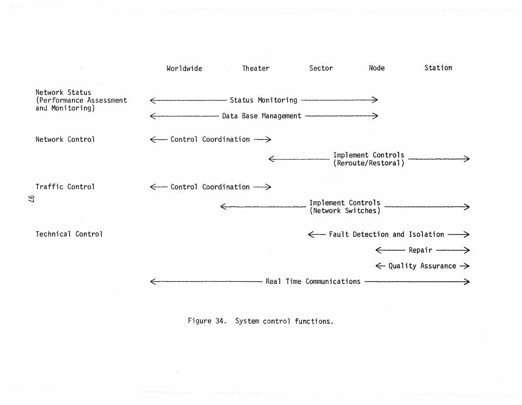
Worldwide Theater Sector Node Station
Network Status(Performance Assessmentand Monitoring)
< Status Monitoring ~
< Data Base Management >
Network Control ~ Control Coordination~
~mplement Control~ ~< (Reroute/Restoral) ,
Traffic Control ~ Control Coordination~
~<: Implement Controls _
(Network Switches)
"-0..........
Technical Control ~ Fault Detection and Isolation ~
~ Repair ~
<- Quality Assurance ~
< Real Time Communications ~
Figure 34. System control functions.
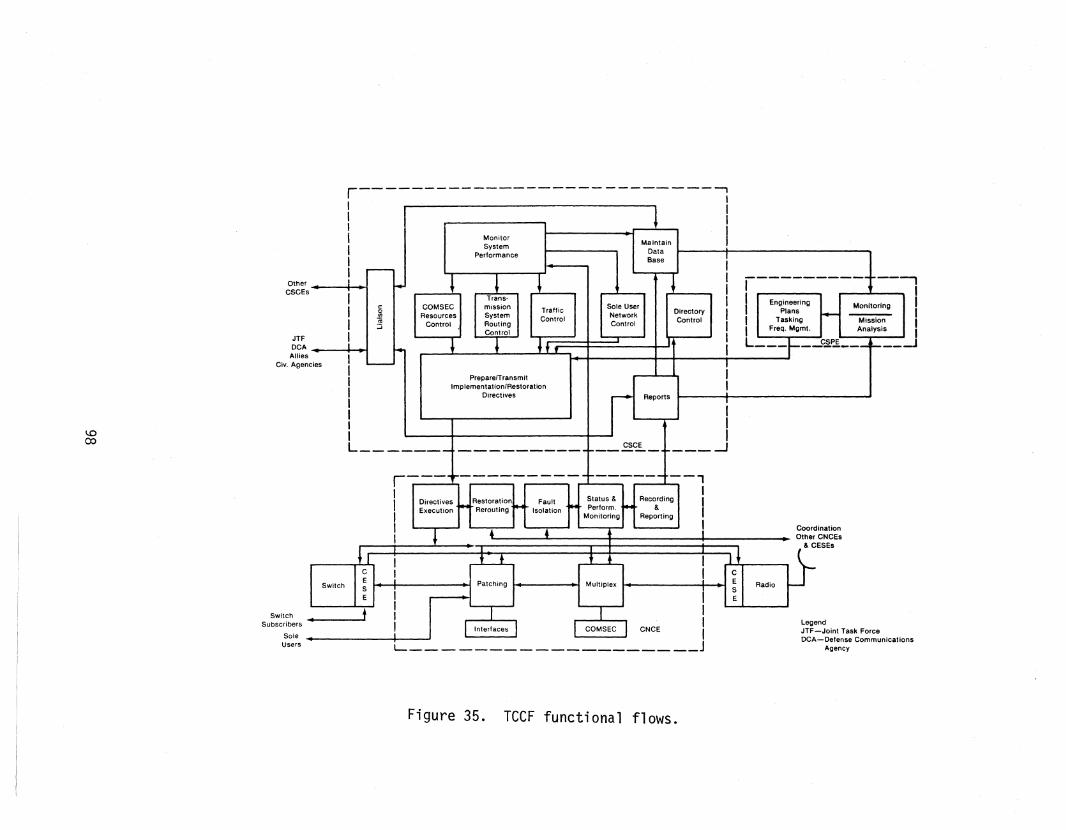
DirectoryControl
1
I
III
~ .-J
IIIIIIII
I I III
Reports
MaintainDataBase
,.........
Sole UserNetworkControl
CSCE----------...------
PreparelTransmitImplementation/Restoration
Directives
L _
r---------------------------~I
I I· i II
IIII I I Monitor
SystemI PerformanceII _rU,
-~hI I Traffic
Control
i 1ff
g~g~s • I. I
JTF
DCA. I' IAllies
Civ. Agencies
\.0CO
LegendJTF-Joint Task ForceDCA-Defense Communications
AgencyL---------- J
r--- --------- --,I . I1
Directives Restoration Fault Status & Recording IExecution Rerouting Isolation Perform. & II Monitoring Reporting
I I CoordinationI Other CNCEs
& CESEs
Switch I Patching Multiplex
CNCE
• tSwitchSubscribers
SoleUsers
Figure 35. rCCF functional flows.

the CNCE are roughly functionally equivalent respectively to the Service ControlFacility (SCF) and the Maintenance Service Center (MSC) of the ETS SYSCON. TheCESE is roughly functionally equivalent to the TRAMCON (Transmission Monitor andControl) system of the DeS. A fourth element of the TCCF, the CommunicationsSystem Planning Element (CSPE), has been discussed but not implemented. The CSPEwould perform functions for higher level of TRI-TAC management, but not on a dayto-day basis. The CSPE would perform functions equivalent to those performed bythe ACOC in the DCS.
One point in Figure 35 that should be emphasized is the connection betweenthe CSCE and DCA, allied, and civil agency system control facilities. This interface is unfortunately not defined in CSCE specifications. This points to the needfor a study to define the SYSCON interoperability requirements. Several documents(TRI-TAC, 1981; the WWDSA transition plan; and the DCS RDT&E five-year plan) provide a general requirement for tactical/DCS SYSCON interoperability. Specificrequirements have not been addressed, however.
The elements of the TeCF will be interconnected using either 2 or 4 kb/ssystem control subchannels for direct processor-to-processor communications. Inaddition a 16/32 kb/s traffic channel can be used to carry up to sev1en SYSCONchannel s.
In contrast to the ETS SYSCON, the TCCF SYSCON message formats, communications protocols, and data elements have been well-defined at this point in time.The message formats and communications protocols are specified in the InterfaceControl Document 004 (TRI-TAC, 1982g) and the CSCE Data Element Dict'ionary (TRITAC, 1982e). A more detailed overview of the TCCF may be found in the CNCE specifications (TRI-TAC, 1981).
The brief overview, given in this section of the SYSCON facilities of ETS andTRI-TAC is provided to show the complexity of the SYSCON interoperab'ility issue.The 'SYSCON i nteroperabi 1i ty issue is seen as a subi ssue of the full, end-to-endinteroperability issue. There appears to be a window of opportunity at thepresent time to address the SYSCON interoperability issue because the ETS SYSCONhas not been fully defined (DCA, 1981a). During the future development of theETS SYSCON provision should be made to provide ETS SYSCON interoperability withTRI-TAC SYSCON. What types of information and their format is not clear at this
point. This question should be addressed during future tasks. The study should
address the following:
99

the level(s) in the hierarchy that ETS and TRI-TAC SYSCONfacilities interoperate,
the types of information that must be exchanged,
the message types and formats,
data elements,
the communications protocol (TRI-TAC uses a modified ADCCPprotocol) that should be used, data transmission rates, and
the encryption and channel coding techniques employed.
It is not entirely clear as to which MIL-DEP has the primary responsibilityfor SYSCON. The U.S. Air Force has some responsibilities, but the U.S. Army
must be involved because SYSCON involves the switches which are U.S. Army responsibility.
6.3 Voice DigitizationOne of the original questions that was posed at the start of this study was
how can networks that utilize different voice digitization techniques be made tointeroperate. The concern at that time was interoperation of the DEB with theEuropean PTT's since the DEB uses ~-law co~panding while the PTT's use A-law companding. This problem turns out to be trivially simple because A-law to ~-law
conversion can be accomplished with a simple table look-up. Bellamy (1982) provides tables that can be used for this purpose. The conversion can be accomplished digitally without the need to revert back to the analog domain. Thereis no problem in the tandem conversions (A to ~ to A to ~ etc.) since it is asimple table look-up function with a one-to-one correspondence of values.
A significantly more difficult problem is the conversion from CVSD to PCMand vice versa. Zakanycz and Betts (1978), report on the development of a deviceto convert 64 kb/s PCM to 16 or 32 kb/sCVSD and vice versa. This conversion isaccomplished digitally. Details of this conversion process may be found in thecited reference.
For end-to-end ETS/TRI-TAC interoperability to be achieved, conversion fromCVSD to peM must be accomplished. Where this conversion takes place is subjectto further study. The most likely contender is a gateway switch. This againputs a further requirement on switch development or modification.
100

6.4 Alternatives for End-to-End InteroperabilityThe preceding three sections discussed the signaling, system control, and
voice digitization aspects of providing full end-to-end interoperability betweenthe ETS and TRI-TAC. The common thread through these discussions was their relati·onshi p to the swi tches of the two networks. The obvi ous concl us ion, then, isthat the alternatives for end-to-end interoperability will involve the ETS switch,the TRI-TAC TTC-39 switch or both. What is not clear is the extent of the hardware and software modifications that must be made. Conceivably, the developmentof a new switch may be required.
The WWDSAcalls for the development of multirate switching and modularly
expandable switches. Themultirate switch will also be capable of combininglower speed bit streams into 16 kb/s or 64 kb/s composite channels through theuse of an internal first-level multiplexer. Several switch makers are currentlyworking on the development of multirate switches. Utilization of commerciallyavailable switches (modified as necessary to provide unique militar.y features)is a desirable approach. The WWDSA multi rate switching requirements and thepotential availability of commercially available switches provides some credenceto the suggestion that the development of a new switch is a viable alternative.
Some suggested alternatives for end-to-end interoperability are:
(a) modification of ETS switches,(b) modification of the TTC-39 switch,(c) combination of (a) and (b), and(d) development of a new multi rate switch.
One problem with (a) and (c) is the fact that the same switch will not be usedthroughout ETS. A switch from a German company will be used in West Germany,while a Canadian switch will be used in the United Kingdom. It is not clear asto what switch will be used as the ETS expands to other countries. One concernwith alternative (d) is that it may be quite expensive.
Before one can perform a detailed analysis of the above alternatives (oreven confirm that the list is a valid list of candidate alternatives to startwith) additional studies are required. As ,suggested in Sections 6.1 and 6.2,signaling and system control are extremely complex issues. Separate, very de-
tailed, studies should be made of both of these technical areas. The focus ofthese efforts should be on establishing requirements for switch modification or
101

development. Section 7 includes a suggested series of tasks for further investigation of the end-to-end interoperability issue.
7. SUMMARY, CONCLUSIONS, AND RECOMMENDATIONSSection 1 of this report discussed the objectives and task breakdown for
studies on survivability, interoperability, reconstitution, and performancerelated issues of the European Defense Communications System that are being con-.ducted by ITS for the U.S. Army Communications Systems Agency. This report isthe output of the task on DCS/TRI-TAC interoperability. Section 1 also itemizedseveral assumptions and constraints that this report is based on. This is followed in Section 2 by a discussion of different concepts of interoperabilityand the terminology used in this report. In Section 3 a discussion is providedof the general interoperability requirements as they have been stated in variousDCA and JCS documents. As noted in Section 4, current planning for AUTOVON/TRITAC interoperability will not result in capabilities that will satisfy the requirements as summarized in Section 3. This background analysis set the stagefor defining conceptual approaches for the digital pipeline level of interoperability in Section 5 and the end-to-end level of interoperability in Section 6.The recommendations stated in Sections 5 and 6, respectively, were to:
1) develop a first level intelligent multiplexer, and possibly inparallel perform initial R&D for the other digital pipelinealternatives outlined in Section 5, and
2) perform further more detailed studies on the end-to-end interoperability issue with emphasis on the system control and CCSaspects.
In Section 3 (requirements), Section 4 (deficiencies), and Section 6 (endto-end interoperability) a common thread is the need for interoperable SYSCONand common channel signaling. The reason for highlighting these parts of theend-to-end interoperability issue is because of the complexity in making thesesubsystems interoperable between the DCS and TRI-TAC.
Throughout this report, emphasis was placed on the following:
1) interoperability and spectral efficiency requirements as specified in DCA and JCS documents, and
2) the translation of these general requirements into more specific requirements for equipment that is the responsibility ofCSA (multiplexers, radios, modems, and switches).
102

The transition from general requirements into specific recommendations is shownin Figure 36. Sections 7.1 and 7.2 will elaborate on the recommendations fordigital pipeline and end-to-end interoperability, respectively.
7.1 Recommended Tasks for Digital Pipeline InteroperabilityFigure 37 presents a diagram of a sequence of decisions that should be made
for the digital pipeline interoperability issue. The decision process starts offwith a cryptic statement of the requirements~ namely that:
1) both DCS-through TRI-TAC-to DCS (D-T-D) and TRI-TAC-throughDCS-to TRI-TAC digital pipeline interoperability is required,and
103

Spectral EfficiencyRequirements
Poor InteroperabilityExcept at VF
Digital PipelineRequirements
End-to-EndInteroperabiIityRequirements
OtherInteroperabil ityRequirements
Voice DigitizationInteroperabilityRequirements
Recommendationfor Additional Study
for Switch Modificationor Development
SYSCONInteroperabilityRequirements
SignalingInteroperabi IityRequirements
Recommendationfor the Development of
an Intelligent FirstLevel Multiplexer
o~
Figure 36. Translation of general requirements as stated by DCA intorecommendations for new R&D programs atCSA.

--'aCJ1
DETERMIN NICSCOMPATIBLE RATES
ALTERNATIVE A
FIRST LEVEL MUX(USER LEVEL)
DETERMINE OPERATIONAL MODESINCLUDING DCS AND TRI-TAC
COMPATlBL E IN PUT AND OUTPUTBIT RATES
PROCURE fiRST LEVELINTELLIGENT MULTI PLEX ER
(SEE FIGURE 1-3)
DET ERMINE NICSCOMPATIBLE RATES
REQUIREMENTS•D-T-D AND T-D-1 INTEROPERABILITY·SPECTRAL EFFICIENCY
SECOND LEVEL MUX(GROUP LEVEL)
DETERMI NE OPE RATIONALMODES AND DATA
RATES
PROCURE ANEWSECOND LEVELMULTIPLEX ER
ALTERNATIVE C
TH IRD LEVEL NUX(DRAMA RADIO INTERNAL
MUX)
DETERMINE OPERATIONALMODES AND DATA
RATES
PROCURE A MODIFIED DRAMARADIO OR POSSIBLY CHANGE
THE SPECifiCATIONS FORTH E RECONSTITUTIONRADIO PROCUREMENT
Figure 37. Digital pipeline interoperability alternatives.

TASK 2DEVELOP MULTI PLEXER
SPECIFICATIONS
I
TASI1OPERATIONAL NODE DEFINITION
1 rTASl4
DETERMINE IMPLICATIONS ONEND-TO-END INTEROPERABIUTY
~TASK 5
LI FE CYCLECOST ANALYSI S
TASK 6PROCURE ENGINEERING
DeSI GN MODELS
TASK.7TEST AND EVALUATION
(l ABORATO RY)
TASK 8TEST AND EVALUATION
(FIELD)
TASK 9PROCUREMENT OF
PRODUCTION NODE LS
TASK 10INSTALLATION AND
OPERATIO N
1TASK 3
OPERATIONAL ANALYSISTO DETERMINE THE NUMBEROf MULTiPlEXERS REQUIRED
r
Figure 38. Recommended tasks for intelligent first levelmultiplexer development.
106

Table 15. First Level Intelligent Multiplexer DevelopmentTask 1: Operational Mode Definition
Subtask Description
determine TRI-TAC/DCS/TRI-TAC modes including the mix ofdedicated data and voice channels
define DCS transparent modes (i.e., FCC-98 replacementmodes)
define TRI-TAC transparent modes (i.e., LGM replacementmodes)
determine modes for interoperating with NICS (or PTTIS)and ATACS
la. estimate the number of traffic channels expected to crossthe TRI-TAC/DCS interface
determine DCS/TRI-TAC/DCS modes including the mix ofdedicated data and voice channels.
1b.
0
I1c.
'-.J
1d.
1e.
1f.

Table 16. First Level Intelligent Multiplexer DevelopmentTask 2: Specifications Development (Detailed Design Study)
Subtask
2a.
2b.
2c.
2d.
2e.
2f.
2g.
2h.
2i .
2j.
2k.
21.
2m.
2n.
20.
2p.
2q.
Description
input module specification- VF input modules- 16/32 kb/s CVSD input modules- data (synchronous and asynchronous) input modules;
what data rates and line codesspecification of what combinations of input modules areallowable (i.e., what combinations of CVSD digital voice,analog voice, and data are allowable)
specification for combined channel group rates that shouldbe used; what input modes of the second level multiplexers(FCC-99 or TGM) should be accommodatedspecification of channel activity detectorsspecification of voice/data detectors
specification of the speech compression technique to be used(e.g., ADPCM) to avoid speech clipping for DSI; furtheranalysis of papers on speech digitization is needed
specification of the channel assignment information (CAl)requirements
specification of the CAl channel encoding (such as theHamming code) requirementsspecification of the frame format (which is variabledepending on the speech activity, number of data channels,etc. )
specification of timing requirements for both internal clockand external clocks; address the question of interoperationof two pleisochronous systems (DEB and TRI-TAC)specification of encryption device interfacesspecification of tech control interfaces in the DCS andTRI-TACspecification of BITE and redundancy requirements
specification of processing requirement for the microprocessor controllerspecification of modularity requirements
specification of physical characteristics including physicalinterfaces, size and weight, and ruggedness requirements
specification of acceptance testing
108

This would consist of a more de,tailedfunctional design of the new multiplexerthan was given in Section 5. The remainder of the tasks depicted in Figure 38are mostly self explanatory as they consist of generic tasks that are germaneto any applied R&D program that has the objective of fielding operational hardware. The life-cycle cost analysis should include both the development costanalysis and O&M (operations and maintenance) cost analysis.
7.2 Recommended Tasks for End-to-End InteroperabilityFigure 39 depicts thereconmended sequence of tasks for a furthE~r i nv.est i
gation of the end-to-end interoperability issue. The first task is to refinethe end-to-end interoperability requirements that were stated in genE~ral termsin Section 3. The identification of specific requirements is a difficult problem because most interoperability requirements are stated only in general terms.
As indicated in Figure 39, Tasks 2 through 5 may be conducted in parallel.Note, however, that the SYSCON interoperability study (Task 2) and the CCS interoperability study (Task 3) are not totally independent tasks. The ETS ControlCommunications Network which provides the transmission media for SYSCON information may be implemented on the ETS common channel signaling network. Therefore,there is overlap between Tasks 2 and 3.
Tables 17 through 20 are expansions of Tasks 2 through 5 depicted in Figure39.
Task 5 warrants further explanation. This task is a survey of state-of-theart switch technology. As indicated in Section 6 of this report, the initialalternative concepts for achieving end-to-end interoperability are ol~iented
around switch modification or development. Of particular interest is the requirement for multirate switching and integrated voice and data switching. Switchdevelopment is, of course, an expensive undertaking. Therefore, it is desirableto utilize available commercial switches (possibly with some modifications toimplement unique military user service features). This is the reason that asurvey of available switch technology is an essential task.
Task 6 consists of the development of alternative concepts for end-to-endinteroperability with the emphasis on switch requirements. Some preliminaryalternative concepts were provided in Section 6 of this report. The alternativeconcepts introduced were:
109

--'---'a
TASK 1REFI NEMENT OF SPECIFIC
REau IREMENTS FO REND -TO-END INT EROPERABI LITY
. .==r=----- --~r__---.---_----.--L-_~
TASK 2 TASK 3 TASK 4 TASK 5STUDY OF INTEROPERABILITY STUDY OFINTEROPERABILITY DETAILED STUDY OF SURVEY OF
BETWEEN ETS SYSCON BETWEEN ETS CCS OTHER MAJOR PARAMETERS EX ISTI NG SWITCHAND TRI-TAC SYSCON AND TRI-TAC CCS OF ETS AND TRI-TAC TECHNOLOGY
_ ..- ---
TASK 6DEVELOP ALTERNATIVE CONCEPTSFOR END-TO-END INTEROPERABILITY
WITH THE EMPHASISON SWITCH REQUIREMENTS
TASK 7EVALUATE AND MAKE
RECOMMENDATIONS FOR SWITCHDEVELOPMENT OR MODIFICATIONS
!TASK 8
DEVELOP AN R&D PROGRAMFOR NEW SWITCH
PROCUREMENT AS NECESSARY
Figure 39. Recommended tasks for end-to-end interoperability.

Table 17. End-to-End Interoperability Task 2: Detailed Studyof SYSCON Interoperability
Description
determine the levels in the system control hierarchy thatETS and TRI-TAC SYSCON facilities shouldinteroperate
define the SYSCON message types and formats
define the data elements
define the communications protocol to be used (TRI-TACuses a modified ADCCP protocol)
determine the types of information that must be exchanged
determine the data rates to be used and the transmissionfacilities to be employed (ETS employs a separatenetwork for SYSCON information transmission)
2g. determine the encryption and channel coding techniques tobe employed
Subtask-2a.
2b.
2c.--J I--J
2d.--J
2e.
2f.

Table 18. End-to-End Interoperability Task 3: Detailed Studyof Common Channel Signaling Interoperability
-..J......N
Subtask
3a.
3b.
3c.
3d.
Description
investigate differences in CCITT #7 CCS and TRI-TAC CCSprotocol s
determine how the CCITT #7 CCS will be modified to meetspecial military requirements for MLPP, community-ofinterest screening, hotline, etc.
perform a detailed comparison of the functional equivalencyof CCITT #7 and TRI-TAC CCS messages
for CCITT #7 and TRI-TAC CCS messages that are functionallyequivalent, perform a fielu-by-field comparison of themessage information content
3e. devise a methodology for implementing new message formatsas required to resolve problems of missing informationfields (derived from Task 3c above) or messages that haveno functional equivalency (derived from Task 3b above)
3f. investigate the ramifications of differences in CCS datarates (CCITT #7 uses 64 kb/s while TRI-TAC uses 16 or 32kb/s)

Table 19. End-to-End Interoperability Task 4: Detailed Studyof Other Major Parameters of ETS and TRI-TAC
.....J
.....J
W
Subtask
4a.
4b.
4c .
Description
study voice digitization techniques for minimizing and controlling the number of tandem conversions betweenCVSD and64 kb/s PCM; determine where to convert from CVSD to PCMand vice versa
detailed study of ETS and TRI-TAC numbering plans and routing control
detailed comparison on the ETS and TRI-TACmultiplexerhierarchies with emphasis on the number of channels ratherthan transmission rate
4d. study of timing and synchronization problems encounteredwhen interfacing two plesiochronous networks
4e. study encryption differences
4f. investigate user service feature requirements for bothTRI-TAC and ETS

---l
--oJ
-I=::-
Table 20. End-to-End Interoperability Task 5: Surveyof Existing Switch Technology
integrated voice/data
- multirate switching
line capacity
- user service features
- ability to interface with both North Americanstandard and European standard digital groups

(a) modification of ETS switches;(b) modification of the TRI-TAC AN/TTC-39 switch;(c) combination of (a) and (b), and(d) the development of a new multi rate switch.
Examination of these alternatives in detail as valid alternatives must be deferredpending the outcome of Tasks 1 through 5. Task 6 then would define these or otheralternatives in detail.
Tasks 7 and 8 involve the evaluation of the alternatives formulated in Task 6and the development of an R&D program for implementing the selected alternative.
8. REFERENCESACC (1980), White paper addressing communications interoperability and network
evaluation, u.s. Army Communications Command, Ft. Huachuca, AZ 85615.
Bellamy, J. (1982), Digital Telephony (John Wiley and Sons, New York, New York) ..
CCITT (1981), Specifications of signalling system no. 7, Vol. VI, CCITT SeventhPlenary Assembly (Yellow Books), ITU, Geneva, Switzerland.
CEEIA (1979), Specification for low speed time division multiplexer/demultiplexer,u.S. Army Communications-Electronics Engineering Installation Agency, Ft.Huachuca, AZ 85613.
Daumer, R. (1982), Subjective evaluation of several efficient speech codes, IEEETrans. on Comm. COM-3D, pp. 665-662, April.
DCA (1967), Overseas AUTOVON network switching plan, Report No. DCAC-370-V-185-7,Defense Communications Agency, Washington, DC 20405.
DCA (1980), Management engineering plan for the Digital European Backbone (DEB),Defense Communications Agency, Washington, DC 20405.
DCA (1981a), European Telephone System (ETS) system engineering architecture, draftDCA Circular, Defense Communications Agency, Washington, DC 20405.
DCA (1981b), Worldwide Digital System Architecture final report, draft report,Defense Communications Agency, Washington, DC 20405.
DCEC (1981), Adaptation of the CCITT Signaling System No.7 for the DSN, Engineering publication No. A02-Bl, Defense Communications Engineering Center,Reston, VA 22090.
Drago, P. G., A. M. Molinari, and F. C. Vagliani (1978), Digital dynamic speechdetectors, IEEE Trans. on Comm. COM-26, pp. 140-145, January.
115

Kuhn, T., J. Chiang, H. Ingorrate, W. Kernazitskas, and N. Seitz (1973), DynamicDemand Assignment (DDA) System Final Report, TR ECOM-0038-1, prepared un·dercontract DAAB07-73-C-0038 for U.S. Army Electronics Command, Ft. Monmouth,NJ 07703.
Langenbucher, G. (1982), Efficient coding and speech interpolation: principlesand performance characterization, IEEE Trans. on Comma COM-30, pp. 769-779,April.
LaVean, G. (1980), Interoperability in defense communications, IEEE Trans. onComma COM-28, pp. 1445-1455, September.
McKee, W. (1982), Architectural considerations for the defense communicationssystem of 2004, IEEE Comma Magazine 20, pp. 5-12, July.
'OINeil, J. B. (1978), Digroup data reduction system, Rome Air Development CenterTechnical Report TR-78-139, Available from the Defense Technical InformationCenter, Alexandria, VA 22314, Report No. AD A056986.
Pound, R. (1979), INTACS system architecture, Available from Defense TechnicalInformation Center, Alexandria, VA 22314, .Report No. AD B048156L.
RADC (1980), Statement of work and prime item development specification fordigital channel efficiency model (DCEM), Procurement Request No. C-0-2019,Rome Air Development Center, Griffiss AFB, NY 13441.
Raulin, J. M., G. Bonnerot, J. L. Jeandot, and R. Lacroix (1982), A 60-channelPCM-ADPCM converter, IEEE Trans. on Comma COM-30, pp. 567-573, April.
Rosner, R. D. (1980), An integrated distributed cont~ol structure for globalcommunications, IEEE Trans. on Comma COM-28, pp. 1505-1515, September.
Seitz, N., J. Chiang, W. Kernazitaskas, T. Kuhn (1975), Dynamic Demand Assignment/Continuous Variable Slop Delta (DDA/CVSD) Project Final Report, TRECOM-0207-1, prepared under contract DAAB07-74-C-0207 for U.S. Army Electronics Command, Ft. Monmouth, NJ 07703.
TRI-TAC (1981), Performance specification for the communications nodal controlelement (CNCE) Type l(V), AN/TSQ-l11(V)(1) and Type III, AN/TSQ-lll(V)(3),TRI~TAC specification # TT-Bl-3006-0096, Joint Tactical CommunicationsOffice, Ft. Monmouth, NJ 07703.
TRI~TAC (1982a), Performance specification central office telephone automaticAN/TTC-39, TT-Bl-l101-00018, Joint Tactical Communications Office, Ft.Monmouth, NJ 07703.
TRI-TAC (1982b), Addendum specification for central office communications, automatic AN/TTC-39 for system expansion, TT-Bl-ll03-0054, Joint TacticalCommunications Office, Ft. Monmouth, NJ 07703.
TRI-TAC (1982c), Performance specification for AN/TRC-170 (V) radio terminal set,TT-Bl-2203-0025A, Change No. 20, Joint Tactical Communications Office,Ft. Monmouth, NJ 07703.
116

TRI-TAC (1982d), Performance specification Communications ~stem Control IlementAN/TYQ-16,TRI-TAC specification TT-Bl-3005-0093A, Joint Tactical Communications Office, Ft. Monmouth, NJ 07703.
TRI-TAC (1982e), Performance Specification Communications ~stem Control IlementAN/TYQ-16, Appendix I - Data Element Dictionary, TRI-TAC specifiicationTT-Bl-3005-0093A, Joint Tactical Communications Office, Ft. Monmouth, NJ07703.
TRI-TAC (1982f), Digital in-band trunk signaling/supervision plan, TRI-TACSpecification No. TT-A3-90l5-0055, Joint Tactical Communications Office,Ft. Monmouth, NJ 07703.
TRI-TAC(1982g), TCCF report and directive message protocols, Interface ControlDocument (ICD-004), Joint Tactical Communications Office, Ft. Monmouth, NJ07703.
TRW (1982), Direct Support Maintenance Manual for Radio Set AN/FRC-170(V), AN/FRC-171(V), AN/FRC-172(V) and AN/FRC-173(V), Army Technical Manual DEP11-5820-863-30.
Wnuk, J. (1981), Considerations of Digital European Backbone interoperability withtactical and European communications systems at the digital group level,Report No. MTR-81W00004, Mitre Corp., McLean, VA 22102.
Yatsuzka, Y. (1982a), Highly sensitive speech detector and high-speed voicebanddiscriminator in DSI-ADPCM system, IEEE Trans. on Comm. COM-3D, pp. 739-750,April.
Yatsuzka, Y. (1982b), High-gain digital speech interpolation with ADPCM encoding,IEEE Trans. on Comm. COM-3Q., pp. 750-761, April.
Zakanycz, P., and W. Betts (1978), Digital communications/interoperabi1ity techniques, Technical Report 73-0304-F, U.S. Army Electronics Command" Ft. Monmouth,NJ 07703.
117


APPENDIX A: EUROPEAN DCS AND TRI-TAC ARCHITECTUREAND EQUIPMENT CHARACTERISTICS
This appendix contains nurnerous figures and tables that provide informationon the ETS, DEB, DRAMA, and TRI-TAC architecture, radios, multiplexers, andswitches. A detailed description of each of these tables and figures is notprovided because they are all fairly self-explanatory. It was necessary toinvestigate the characteristics of these DCS and TRI-TAC equipments in order tohave sufficient background to ~generate alternatives for achieving DCS/TRI-TACinteroperability. The figures and tables of this appendix are the result ofthat investigation. Because they are thought to be useful reference material,they are included in this report. If detailed descriptions of this equipmentare desired the reader is referred to the bibliography at the end of thisappendix.
The figures and tables are grouped by subject matter as follows:
Subject.ETS architectureTypical DEB nodeDRAMAETS switch (KN-10l)Evolution of tactical communicationsTRI-TAC typical architectureTRI-TAC equipment listingTRI-TAC multiplexersTRI-TAC radiosTRI-TAC switches
FiguresA-l to A-2
A-3A-4 to A-5
A-6A-7
A-8 to A-10A-ll
A-12 to A-13
Tables
A-l to A-5A-6
A-7A-8 to -A-ll
A-12 to A-13A-14
Pages120-121
122123~130
131132133
134-136137-143144-146147-149
119

EXISTINGNON-MILITARY EO MILITARY EXCHANGES
EO - end officeISC - intermediate
switching center
--'Na
SWITCHES
FRG - SIEMENS KN10lUK - NORTHERN TELCON OMS-lOD/200Elsewhere-?
TRANSMISSION
DEB (PCM-24)Leased Digital (PCM-30)leased Analog 12W and 4WIU.S. Owned 2W and 4W Cable
Figure A-l. ETS architecture.
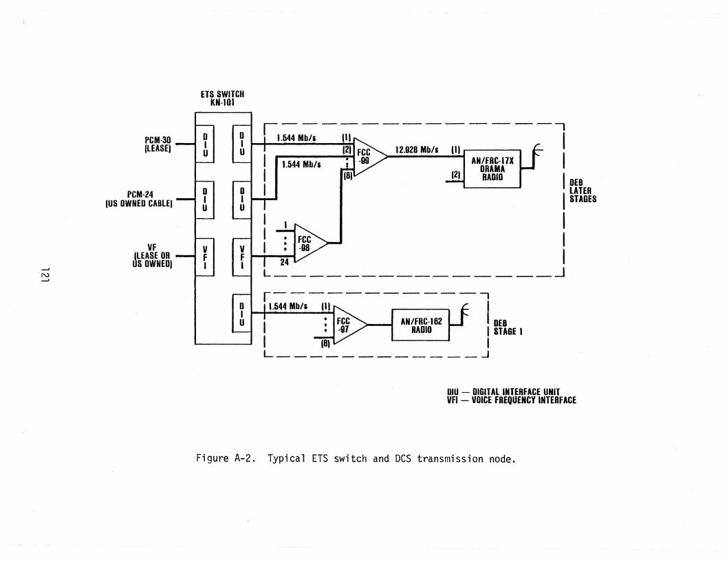
ETS SWITCHKN-l01
VF
--J
JLEASE OR -l V I IfN
S OWNED) F
--'
. I
I I0IU
r--------------.1.544 Mb/s 11) I
(2) FCC 12.928 Mb/s 11) ....------.,I 1544 Mb/s ; -99 AN/FRC-I7X I. DRAMAI (8) (2) RADIO IDEB
I LATERISTAGES
II
I I 24 V IL --3
r-·--------··-· -.-,1.544 Mb/s (1) I
: FCC AH/FRC-162 I DEB• -91 RAPID I STAGE I
I (8) IL -'
oIU
oIU
oIU
oIU
PCM·30(LEASE)
PCM-24(US OWNED CABLE)
DIU - DIGITAL INTERFACE UNITVFI - VOICE FREQUENCY INTERFACE
Figure A-2. Typical ETS switch and DeS transmission node.

DUERH' 'DOE' D""D£NDEn HO(NE '08'" .ltr" 'Sl'"
r•c'I GU.., ., TI FttD8tR8 p:tU
MAT·FEt
'H 5 tDF·f(t ""Mo,~kd'~'bJ'C FCC 4 KAl.FEt. rcc c c c . C
HUM IJ DD 3 ·00 J 81.8 hI J 'G4.1''''
N l0I10ElIlOE": , ~ - , 1 { {N
A A A
tiilAlT£HottiOrtRATm.
Figure A-3. Typical DEB nodes using DRA~1A equipment.
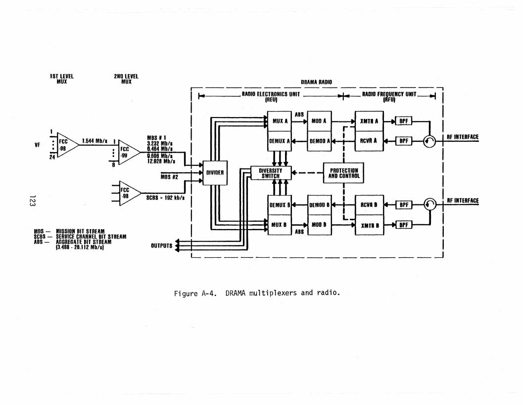
III!RFINTERFACE
PROTECTIONAtfD CONTROl
II
R~
LMOD 8 I •
DEMon B
III
L . --l
DRAMA RADIOr-._----- -- -- -- -- -- -- -- ---- -,
I f-e RADIO ELECTRONICS UNIT -+--- RADIO fREQUENCY UNIT -----I IIREUJ . ·IIIFUJ----....
I ABS II MUX A MOD A r II DEMUX A DEMOO A ' RF INTERFACE
I ~
MDS 112 I III DIVIDER
OUTPUTS. I '
9.690 Mb/s12.928 Mb/l
MOS" 13.232 Mb/l8.484 Mb/l
SCBS = 192 kb/l
FCC.gg
2ND LEVELMUX
8
1.644 Mb/a
1ST lEVELMUX
FCC·98..... /
24
MOS - MISSION BIT STREAMSCUS - SERVICE CHANNEL BIT STREAMADS - AGGREGATE BIT STREAM
13.488 - 28.112 Mb/sl
VF
.....J
NW
Figure A-4. DRAMA multiplexers and radio.
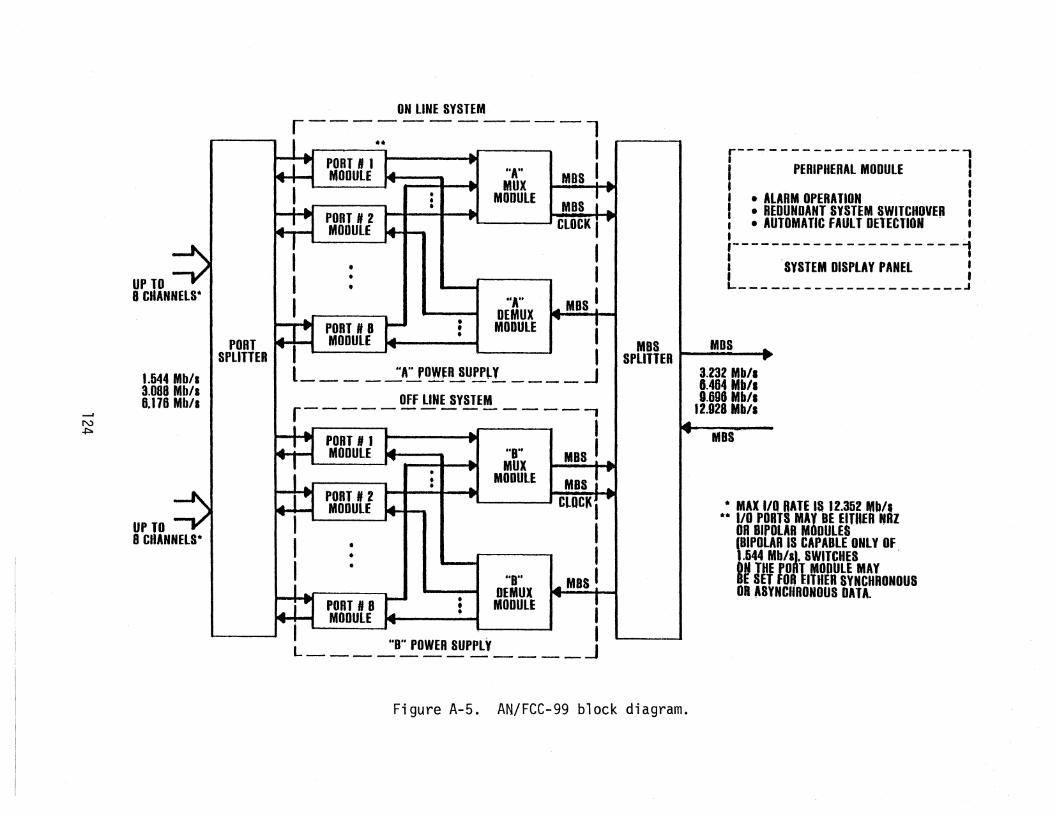
r--------------------,i PERIPHERAL MODULE !I • ALARM OPERATION II • REDUNDANT SYSTEM SWITCHOVEP ;I • AUTOMATIC FAULT DETECTION •, ..,---- - -- - - - - - - - - - - - - - - -1I 'SYSTEM DISPLAY PANEL :L------- J
• MAX I/O RATE IS 12.352 Mb/l.* 110 PORTS MAY BE ElftiER NHZ
OR BIPOLAH MODULES(BIPOLAR IS CAPABLE ONLY OF.1.544 Mb/s), SWITCHES
INTHE PORT MODULE MAYESET FOR EITHER SYNCHRONOUS
OR ~SYNCIIRONOUS DATA.
MOS
3.232 Mb/.8.464 Mb/.0.690 Mb/.
12.028 Mb/l
MBS .
MBSSPLITTER
MBS
ClOCIt I
II
MBS I~
"A"DEMUX
MODULE
fiB"MUX
MODULE
"A"MUX
MODULE
"0"BEMUX
MODULE
•••
•••
ON LINE SYSTEMr--------.---1
-----.* . IMBSI~
ponTSPLITTER
1.544 Mb/s3.088 Mb/a6.116 Mb/a
UP TO8 CHANNELS·
UP TO8 CHANNELS"
--'N+:::-
Figure A-5. AN/FCC-99 block diagram.

Table A-1. Characteristics of DRAMA Radio
Frequency: 4 GHz and 8 GHz
Modulation: QPSK andQPR
IF: 70 MHz
Bandwidth: 3.5, 7.0, 10.5, 14.0, or 20 MHz dependingupon modulation andABS data rates
Frequency and Space Diversity - no adaptive equalization
Aggregate Bit Stream Data Rates:
MBS Rate 1 MBS 2 MBS·s
3.232 3.488 6.7206.464 6.720 13. 1849.696 9.952 19.648
12. 924 13. 184 26.112
125

Table A-2. DRAMA Radio Versions
AN/FRC-170 (V) 4 GHz, space diversity-171 (V) 8 GHz, space diversity-172 (V) 4 GHz, frequency diversity-173 (V) 8 GHz, frequency diversity
Radio # of MBS ASS Bandwidth(V) MBS Rate Rate Modulation (MHz)Number Ports (Mb/s) (Mb/s)*
2 2 3.232 6.720 QPSK 7
1 1 6.464 6.720 QPSK 7**5 2 6.464 13.184 QPR 7**9 2 6.464 13. 184 QPSK 14**
3 1 9.696 9.952 QPR 76 1 9.696 9.952 QPSK 10.57 2 9.696 19.648 QPR 10.5
11 2 9.696 19.648 QPSK 20
4 1 12.928 13. 184 QPR 7**8 1 12. 928 13. 184 QPSK 14**
10 2 12.928 26.112 QPR 14**12 2 12.928 26.112 QPSK 20
*Inc1udes 0.192 Mb/s SCBS and 0.064 Mb/s overhead.**Reconstitution Radio Modes.
126

==-'N.........
Table A-3. FCC-98 Configuration Options
Data Timing Module 24 ch version or 3/6/12/24 channel version
Bite 1 each
Input Power Module -48 VDC or 117 VAC or 230 VAC
VF Channel Modules < Max. No. in mode - No. Data Channel Modules
Data Channel Modules
3/6/12/24 channel version 24 channel versionchannel mode data format
3 6 12 24 bipolar NRZ
0-20 Kb/s Asynchronous 3 6 12 121 122 121
50 kb/s Asynchronous 3 6 12 121 122 121
56 kb/s Synchronous 3 6 12 121 122 121
64 kb/s Synchronous 3(0) 9(0) 121 122 121
128 kb/s Synchronous 1(0) 4(0) 12(6) 62 12(6)
256 kb/s Synchronous 2(0) 6(3) 32 6(3)
512 kb/s.Synchronous 1(0) 3(1 ) ,2 3(1 )
1) Limited by power consumption could go to 18.2) Limited by lis density.3) Numbers in () are from specification.

Table A-4. AN/FCC-99 Second Level Multiplexer I/O Rates
Input
3 Rates: 1.544, 3.088, 6.176 Mb/s
2 Modes: synchronous/asynchronous
2 Formats: NRZ/bipo1ar
Output
4 Rates: 3.232, 6.464, 9.696, 12.928 Mb/s
128

Table A-5. FCC-99 Port Data Rate Combinations
Port Slots MinimumMBS
1 2 3 4 5 6 7 8 Rate
1.544 3.232
1 .544 1.544 3.232
1.544 1.544 1.544 6.464
1.544 1.544 1.544 1.544 6.464
1.544 1.544 1.544 1.544 1.544 9.696
1.544 1.544 1.544 1.544 1.544 1.544 9.696
1.544 1.544 1.544 1i.544 1.544 1.544 1.544 12.928
1.544 1.544 1.544 l,t 544 1.544 1.544 1.544 1.544 12.928
3.088 3.232
3.088 1.544 6.464
3.088 1.544 1.544 6.464
3.088 1.544 1.544 1,.544 9.696
3.088 1.544 1.544 1.544 1.544 9.696
3.088 1.544 1.544 1.544 1.544 1.544 12. 928
3.088 1.544 1.544 1.544 1.544 1.544 1.544 12.928
3.088 3.088 6.464
3.088 3.088 1.544 9.696
3.088 3.088 1.544 1.544 9.696
3.088 3.088 1. 544 1.544 1.544 12.928
3.088 3.088 1.544 1.544 1.544 1.544 12.928
129

Table A-5. (continued)
Port Slots MinimumMBS
1 2 3 4 5 6 7 8 Rate
3.088 3.088 3.088 9.696
3.088 3.088 3.088 1.544 12.928
3.088 3.088 3.088 1.544 1.544 12.928
3.088 3.088 3.088 3.088 12.928
6.176 6.464
6.176 1.544 9.696
6. 176 1.544 1.544 9.696
6.176 1.544 1.544 1.544 12.928
6.176 1.544 1.544 1.544 1.544 12.928
6.176 3.088 9.696
6.176 3.088 1.544 12.928
6.176 3.088 1.544 1.544 12.928
6.176 3.088 3.088 12.928
6.176 6.176 12.928
130

Table A-6. Features of KN-10l Switch
Line Trunk Group Features
Subscriber Line Circuits, Analog (SLCA) - converted to64 kb/s digital
Subscriber Line Circuits, Digital (SLCD)
Attendant Consoles - digital interface
Trunk Lines - E&M, CCITT Rl/R2 signaling
PCM Digital Interface Units - PCM-24 and PCM-30maximum of 4 DIU'sper LTG
Subscriber Features
attendant recall, conferencing, camp-on, speed calling,call forwarding, etc.
Attendant Features
busy override, busy verification, displays, nightservice, information console, etc.
Switching System Features
AMA, classes of service, redundancy, priority andpreemption, etc.
131

--'WN
en~W.en>(J)
WI
(,)
I INTACS ARCHITECTURE fI TRI-TAC ~
l IATACS I
I ATACS I
1960 1970 1980
CALENDER YEAR1990 2000
Figure A-6. Evolution of Army tactical communications to theINTACS objective system.

....••'1.1.WIII",1
11111
~.....
TAC11CM...,aunTEn.I'"
lUI••
i.e AI' lB. UIE O"E F1ft.L CltM. ,.. mlldAIIlIM U8Ell/2 CIAI.n FOR milIEU
CIICE.I/TSO·' " COMMUNICATION. MOOR CONTROl WIIEI'
MElfii
III. 144.2511.•I". 111.111. l~.'" TRAFFIC CIII. GIl"
IRUTtI
nltl: • _·,.....xtom'."!!!' -Itlltn lim, llIOur Ittlf mlt[I :- "I:!'JE ..UlI"UX£1I co .f' =~1U,,'':.:::;,rf~'Wr8t(•... - ••'flIlIRflUP .Ol"",Utl
• =UW f"''\Ull==11l...1C1 ~'"Tll''' '"0UP MO•• CAllE ""'"
"'n=\I Iml~II""'"CII- aRE II......'
'1 ''''1 If ""J Itl n,. I i&e "".I_t«l"-l na_~IJ/.
II HI 'fl/, 112 ""., 'II ..,. '7' ..,.
11''''.
IlUM ~ INPUT: ii ••,.,u .",. ,......DUfPUT: 1! ''''t,t44"I.
I ~
~.
: II&.ii
*:IJ:,
ww
Figure A-7. Typical TRI-TAC equipment interconnects.

Table A-7. Equipment Being Developed for TRI-TAC
Switches
AN/TTC-39AN/TTC-42SB-3865
AN/TTC-39AN/TYC-11AN/GYC-7
TRI-TAC Equipment
large Circuit SwitchMedium Circuit SwitchSmall Unit level Circuit Switch
large Message SwitchMedium Message SwitchSmall Unit level Message Switch
EquipmentStatus*
Ju1 83May 86May 86
July 83TBD
May 84(lOT)
Comments
600 line switch; expandable to 2,400 lines150 line switch; up to 24 analog30 line switch; 2 or 3 switches can beconverted
Store and forward message switch; 50 lines12 line switch; part of MTCC12 line switch
Note: all switches are digital with varying degrees of analog termination capability.
Radios
--'w~
AN/TRC-170
AN/GRC-144 (mod)
C-6709
Digital Tropo Radio
Short Range Wideband RadioShort Range Wideband Radio (SRWBR)Basic Net Radio Interface Unit (BNRIU)
Secure Digital Net Radio Interface Unit (SDNRIU)
Jun 84
Jan 84TBD
Apr 83
May 86
4.4-5.0 GHz; 2.048 Mb/s; 200 miles (320 km);4 digital groups of 15 channels eachUsed in AN/TRC-139 (mod) and AN/TRC-175
Connects single channel radios to analoginput· of switchConnects single channel radios to digitalinput of switch
Multiplexers, Modems, and Associated Equipment (Digital Group Multiplex Family - DGM)
TD-1233TD-1234TD-1235TO-1236TD-1237
TO-1218TO-1219
Remote Loop Group Multiplexer (RlGM)Remote Multiplexer Combiner (RMC)Loop Group Multiplexer Combiner (LGM)Trunk Group Multiplexer (TGM)Master Group Multiplexer (MGM)
Low Speed Pulse Restorer (LSPR)High Speed Pulse Restorer (HSPR)
May 84May 84May 84May 84May 84
May 84May 84
4 channels8 channels17 channels4 groups12 groups
*Equipment status dates are initial production dates unless otherwise indicated. Dates obtained from TRI-TAC office, April 1982 - Not forpublic release.
lOT - initial operational test; TBD - to be determined; UNK - unknown or unavailable.

TRI-TAC Equipment
Table A-7. (continued)
EquipmentStatus* Conments
Multiplexers, Modems) and Associated Equipment (DJgital Group Multiplex Family - DGM) (cont.)
MD-1023MD-1024MD-1025
MD-1026MD-1065
C-10716C-10717
TS-3647
Low Speed Cable Driver Modem (LSCDM)High Speed Cable Driver Modem (HSCDM)Remote Loop Group Multiplexer Cable Driver (RLGM/CD)
Group Modem (GM)103 modem
Orderwire Control Unit (OCU-1)Orderwire Control Unit (OCU-2)
Cable Orderwire Unit (COU)
May 84May 84May 84
May 84May 84
May 84May 84
May 84
2.048 Mb/s18.720 Mb/sInterfaces with 2 RLGM's; 2 mile cablelengthInterfaces with 6 group multiplexers
OCU's provides operator access to analog anddigital voice orderwires. Used with different·assemb1ages.Cable link test set
Tactical Communications Control Facilities (TeeF)
.....w(J1
AN/TSQ-l11AN/TYQ-16
Conmunications Nodal Control Element (CNCE)Communications System Control Element (CSCE)
Nov 85UNK
Technical controlNear real-time allocation of resources;routing control·
Note: CSCE's and CNCE's are interconnected by 2 kb/s SYSCON channels.
Tennina1s
TA-954/TA-984CV-3591
TSEC/KY-68, TSEC/KY-78
AN/UXC-4
AN/UGC-74
Digital Nonsecure Voice Terminal (DNVT)Advanced Narrowband Digital Voice Terminal (ANDVT)
Digital Subscriber Voice Terminal (DSVT)
Tactical Digital Facsimile (TDF)
Single Subscriber Tenminals (SST) Keyboard Print
Oct 83Jun 83
(lOT)UNK
Sep 84
Aug 85
4 wire, 16/32 kb/s CVSD2,400 b/s LPC-10; interface with SDNRIU
4 wire, 16/32 kb/s CVSD; TDF/SST/DTEinterfaces16 shades of grey; 1.2, 2.4, 4.8, 9.6,16, 32 kb/sIntelligent TTY; compose, edit, store,transmit and receive messages
*Equipment status dates are initial production dates unless otherwise indicated. Dates obtained from TRI-TAC office, April 1982 - Not forpublic release.
lOT - initial operational test; TBD - to be determined; UNK - unknown or unavailable.

Assemblages
Table A-7. (continued)
TRI-TAC Equipment
Modular Tactical Communications Center (MTCe)
Mobile Subscriber Equipment (MSE)
Modular Record Traffic Terminal (MRTT)
EquipmentStatus*
TBD
TBD
Conments
Includes TYC-ll, terminals, and COMSECdevicesWill include switches, transmission,control, COMSECFamily of terminals; includes SST
W0'\
*Equipment status dates are initial production dates unless otherwise indicated. Dates obtained from TRI-TAC office, April 1982 - Not forpublic release.
lOT - initial operational test; TBD - to be determined; UNK - unknown or unavailable.

9.36 OR18.72 Mb/s(1144 TC)
{72 kb/s TO4.915 Mb/s
144,288 OR576 kb/s(17 TC)
--------------112 .
INPUTS
144 kb/s TO4,.608 Mb/s r(132 Te)
If---- -------~265/512288/576 kb/s'('17'TC)
7,8,15OR 17
USERS
4 OR 8USERS
4 {72 kb/s TOINPUT 2.304 Mb/s
72 OR144 kb/s4
USERS
--'W""""'-J
• RLGM =
• RMC
• LGM• TGM
=
==
REMOTE lOOP GROUPMUlTIPlEXERREMOTE MULTIPLEXERCOMBINERlOOP GROUP MULTIPLEXERTRUNK GROUP MULTIPLEXER
• MGM• TC
• USER
= MASTER GROUP MULTIPLEXER= TRAFFIC CHANNELS
(max capability shown)= 16 or 32 kb/s DIGITAL
SUBSCRIBER
Figure A-8. TRI-TAC multiplexer hierarchy.
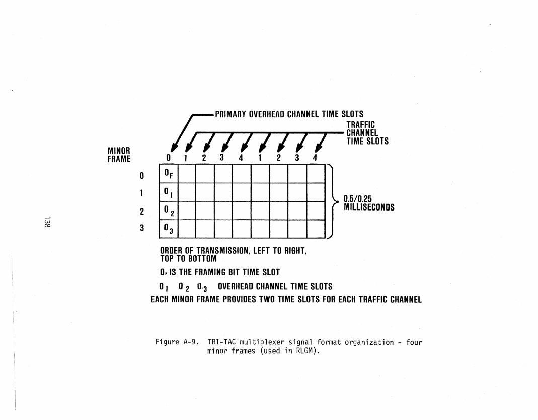
MINORFRAME
iJ PRIMARY OVERHEAD CHANNEL TIME SLOTSTRAFFIC
~~~~~~..~~~~~~~~~~~¥~r~TS012341234
.......wco
o1
2
3
0.5/0.25MILLISECONDS
ORDER OF TRANSMISSION, LEFT TO RIGHT,TOP TO BOTTOM
OF IS THE FRAMING BIT TIME SLOT
o1 0 2 0:3 OVERHEAD CHANNEL TIME SLOTSEACH MINOR FRAME PROVIDES TWO TIME SLOTS FOR EACH TRAFFIC CHANNEL
Figure A-g. TRI-TAC multiplexer signal format organization - fourminor frames (used in RLGM).

..... MAJOR fRAME tiME PERIOD ....= 0.5/0.25 MILlIS£COHDS
MINOR I h MINOR~ MINOR~ IIIIDR. __FRAME , FRAME2· FRAME 8 FRAM~ Io '. 2 3 fl.. It 12. 3 It· i I ! 3 ., 0 • 2 TIME BLOT TIME .rgICr==O [5[II]~~= =~~~ °t ~==D ~~~~-~~
--a.~ PRIMARY OVERIIEAO CHANNEl TIME SLOT. O. IS THE FRAMINO TlMl iL8T
o TRAFFIC CIIA.MEL TIME SLot
MAJOR FRAME COMPOSED OF l'OIiT MINOR fRAMESMU'On fRIlME ALLOCATES ONE TIME SLOT TO OVERIt£AO CIIANHEL Atio ONE TIMt SLOT TO EAcH
'TRAFfiC CHANNEl. 81t INfrRlAClD.
MAJOR flAMEfiXED LE OT" ."8.6/0.26 MILUIECONDI
- _. - - - - - -,........u.-
tI
0,
0,
0 3
04
O.
o•
0,
r
3
~
8
•J
MINOR rHAME'
o
III SERIAltZtO BtT STREAM REPRESENTATION OR MAJOR fRAMt .c.. PRIMARY OVERHEAD CHANNEL ilME SLOTS
117711111 I TRAFFIC CHA.tlEL TIME SLITS--'W\.0
onDER OF TRANSMISSION. lEFT TO RIOHT. TOP TO BOTTOM
'b' RECTAflGULAII ARRAY REPRESENTATION OF MAJOR FRAME ORoANIZATION
Figure A-10. TRI-TAC multiplexer signal format organization - eightminor frames.

....J
+::=ao
Table A-8. Characteristics of TRI-TACMu1tip1exers
Input Characteristics Output Characteristics
Equipment Number Bit Rates MaximumFormat Number of Bit Rates FormatTraffic
Channels Groups Channels Groups Channels
Remote Loop up to 4 --- 16 or 32 --- COP 4 72 kb/s for 16 kb/s channels COP(RLGM) kb/s 144 kb/s for 32 kb/s channelsTD-1233
Remote up to 8 1 16 or 32 72, 128, 144 COP 16 128, 144, 256, 288 COPMultiplexer kb/s 256, or 512, or 576 kb/sCombiner 288 kb/s(RMC)TO-1234
Loop Group 7, 8, 15 --- 16 or 32 --- COP 17 # chns NRZMultiplexer or 17 kb/s --7- 128/256 kb/sTD-1235 8 144/288 kb/s
15 256/512kb/s17 288/576 kb/s
Trunk Group --- up to 4 --- 1. 128, 256, 512, NRZ 143 1. 128,256,512,1,024, NRZMultiplexer 1,024, and 1,536, 2,048, and(TGM) 2,048 4,096 kb/sTD-1236 2. 144, 288, 576, 2. 144, 288, 576, 1,152,
1, 152, and 2,304, and 4,608 kb/s2,304 kb/s
Master Group up to 12 1. 128, 256, 512, NRZ 1,144 9.36 and "18.72 Mb/s NRZMultiplexer 1,024, 1,536,(MGM) 2,048, andTD-1237 4,096 kb/s
2. 72, 144, 288,576, 1,152,2,304, and4,608 kb/s
3. 4,915.2 kb/s

~......
Table A-g. Remote Multiplexer Combiner (RMC)
16 kb/s Input Channels 32 kb/s Input Channels
Number of Number of Total Input Group Output Number of Number of Total Input Group OutputInput Input Number of Rate (kb/s) Bit Rate Input Input Number of Rate (kb/s) Bit Rate
Channels Groups Channels (kb/s) Channels Groups Channels (kb/s)
3 1 7 72 128 3 1 7 144 256(4 channels)
7 --- 7 --- 128 7 --- 7 --- 256
8 8 --- 144 8 -- 8 --- 288
4 1 8 72 144 4 1 8 144 288(4 cha nne1s ) (4 channels)
8 1 15 128 256 8 1 15 256 512(7 channels) (7 channels)
8 1 16 144 288 8 1 16 288 576(8 channels) (8 channels)
Notes: a. 1 equal rate channel is used .for overhead including framing and telemetry.b. All channel quantities refer to traffic channels.

.....I.
+:=N
Table A-l0. OGM Equipment Usage
"
TRI-TAC Assemblagef--..
AN/TRe- AN/TRC- AN/TRC- AN/TRC- AN/TRe- AN/TRC- AN/TRC- AN/TSQ- AN/TSQ- AN/TTC-OGM Unit 173 174 175 138 170 170 170 111 111 42MOO Vl V2 V3 Type I Type III
TO-1233 (RLGM)
TO-1234 (RMC) 4
TO-1235 (LGM) 2 2 2
TO-1236 (TGM) 2 1 1 1
TO-1237 (f.1GM) 2 1 2 1
MO-1023 (LSCOM) 2 3 1 1 1 8 6 1
MO-1024 (HSCOM) 2 1 2 1
MD-1025 4 6 4(RlGM/CO)
MO-1026 (GM) 2 1 6 2 1 1 1
MO-1065 1 2(GRC-l03 MODEM)
C-10716()/TRC 1 1OCU-1
C-10717()/TRC 1 1OCU-2

Ta b1e A-ll. Digital Transmission Group Bit Rates (Nominal)
Total Channels N Bit Rate at Bit Rate at(Includes Primary Maximum VDR of 16 kb/s VDR of 32 kb/sAvailableOverhead) Traffic Channels (kb/s) (kb/s)
4 1/2 1 4 72 144
8 7 128 256
9 8 144 288
16I
15 256 512
18 17 288 576
32 31 512 1024
36 35 576 1152
48 47 1536
64 63 1024 2048
72 71 1152 2304
96 95 1536 2
128 127 2048 4096
144 142 2304 4608
Notes: 1. 8/16 kb/s overhead channel, 16/32 kb/s traffic channels.2. TGM capability only.
143
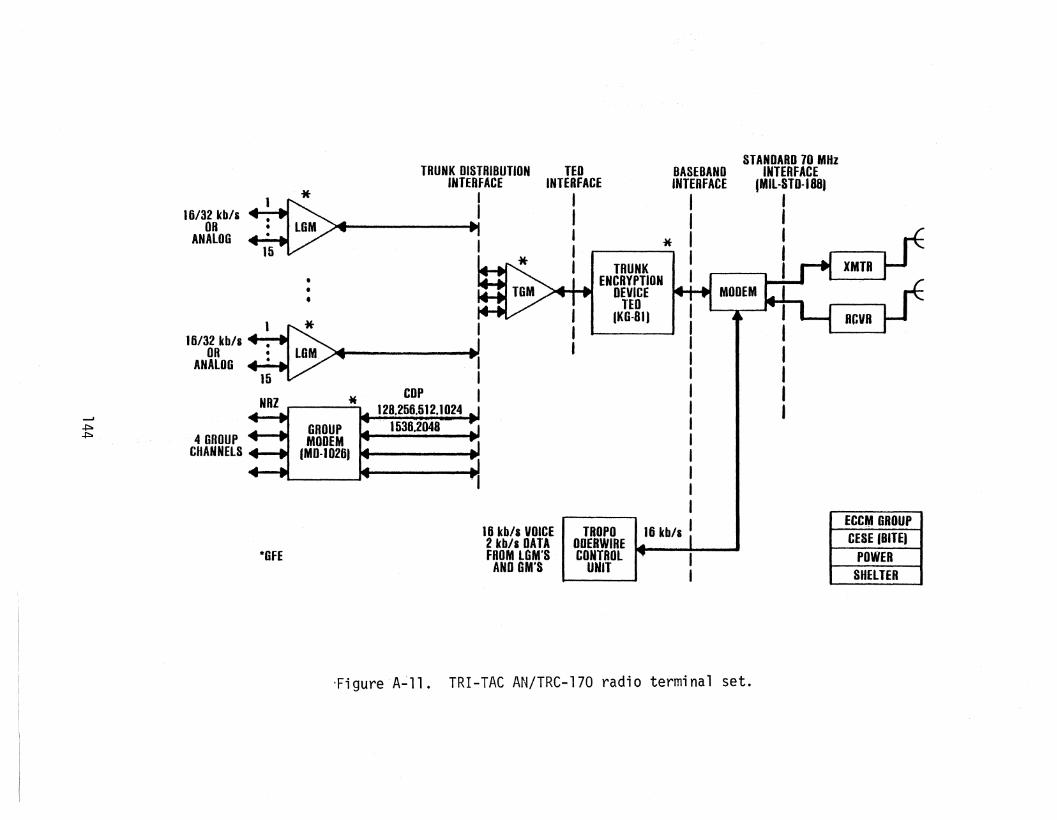
*
TRUNK DISTRIBUTION TEO
16/32 kb/s :TIINTERFACE INTERFACE
BASEBANDSTANDARD 70 MH
OR •
I
ANALOG : ~~4I
IINTERFACE
INTERFACE Z
ItMIL-STD-ISB)
11 II
I II I
•
I * I I
•I I
• l:::I IGM
II I
16/32 kb/s -I _""'ft"
OR
I
ANALOG -15 -V
--J.
COP
-IS
*-+==a 4GROUP~
~ 128.256.512.1024
CHANNELS
GRnUp _ 1536,2048
*GFE
16 kb/a VOICE2 kb/s DATAFROM LOM'S
AND GM'S
TROPOODERWIRE •• ' •CONTROL
UNIT
ECCM GROUPCESE (BITE)
POWERSHELTER
-Figure A~ll. TRI-TAC AN/TRC-170 radio terminal set.

Table A-12. AN/GRC-144 Radio Characteristics
-='+::0'1
Frequency:
Tuning:
Mode:
Range:
IF Bandwidth:
Da ta Rates:
BER for asimulatedpath lossof 107.7 dB:
Interfaces:
AN/GRC-144 (V3)
4.4-5.0 GHz
6,000 RF channels(100 kHz steps)
high capacity LOS
5.0 MHz
1,024, 1,152, 1,536, 2,0482,304, 4,096, 4,608,
4915.2 kb/s
10-5
MGM on channel side,gt"oup modem (GM)
AN/GRC-144 (V4)
14.4-15.0 GHz
2,000 RF channels(300 kHz steps)
short range wideband radio(SRWBR) - IIdown the hill
communications"
8 km for data rates from9.36-18.72 Mb/s
24 km for data rates upto 9.36 Mb/s
10 MHz for 9.36 Mb/s data rate20 MHz for 18.72 Mb/s data rate
same as for V3 plus 9.36and 18.72 Mb/s
10-5
high speed cable drivermodem (HSCDR), master group
multiplexer (MGM)

Table A-13. AN/TRC-170 Radio Characteristics
Frequency: 4.4-5.0 GHz
Tuning: 100 kHz steps
Mode: Troposcatter or LOS
1I: standard 70 MHz (MIL-STD-188)
IF Bandwidth: 3.5 and 7.0 MHz
Three Sets Having Differing "Capabilities:
- Set 1: 200 mile (320 km) range; capable oftransmitting simultaneously at twodifferent frequencies
- Set 2: 150 mile (240 km) range; two frequencies
- Set 3: 100 mile (160 km) range; single frequency
LOS Mode:
- All sets are capable of LOS mode
- Lower power; interface with existing LOS antennas
- 3.5 MHz IF bandwidth only
Data Rates: 128,256, 512,1,024, 1,536, 2,048 kb/s (bothLOS and tropo modes)
BER: 10-5
146
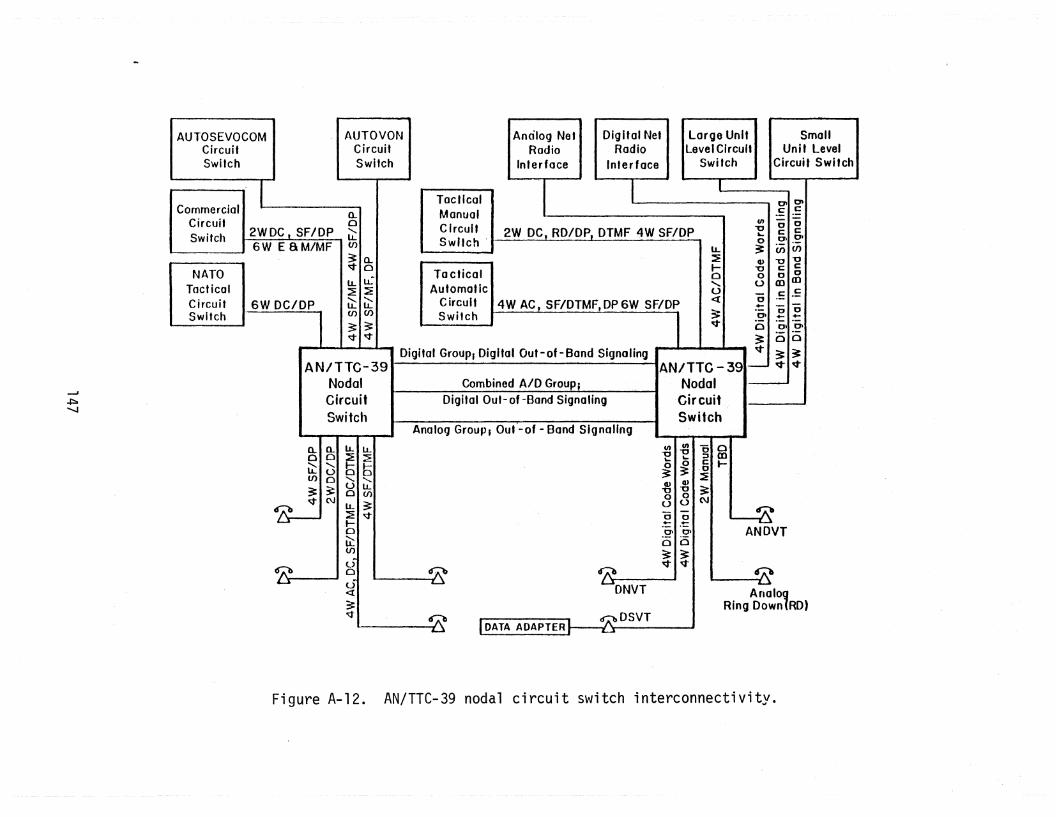
Analog GrouPI Ouf-of - Band Signaling
Digital Group, Digital Out-ot-Band Signaling
AUTOSEVOCOMCircuitSwitch
AN/TTC-39NodalCircuitSwitch
g-Ig'
SmallUnit Level
Circuit Switch
cCOt
Cl>"'0o
U
I
LL:efe"u<{
;:v
Lorge UnitLevel Circuit
Switch
o.... --.- 0 0oa .... +-(5 00. 00-~ 0 av ~.~
AN/TTC- 391 v vNodal --CircuitSwitch
1
Digital NetRadio
Inter face
I
Analog NetRadio
Interface
2W DC, RD/DP, DTMF 4W SF/OP
4W AC. SF/OTMF.OP6W SF/01
Combined AID GrouPiDigital Out-of -Bond Signaling
TacticalManualCircuitSwitch'
To eticolAutomatic
CircuitSwitch
AUTO VONCircuitSwitch
1
6W DC/DP
2WDC, SF/DP6WE 8M/MF
NATOTocticalCircuitSwitch
CommercialCircuitSwitch
~"""'-J
0.. a..00
~ 0(f) 0
:: ~~ C\J
~
~
IJ... LL:E~
55III III -10
......... "-
"C -0 0
ULL
...... ~ m
Den
o 0 C I-~ ~c
LL ~
~ Q) ~
:E ~
'U "0 3:
.t-
0 0
0
u u (\J
LLI~
U)
<...)
ANDVT
0
u<t
I;:
DNVT~
~.
47b
Ana'o~
d':"'b DSVTRing Down RD)
Figure A-12. AN/TTC-39 nodal circuit switch interconnectivity.

Manual TacticalMessage Relay
InventoryTTY
Terminal
I
InventoryData
Terminal
ModularRecord
-I .Traffic
Terminal
AUTODINNodal Nodal
Switching Message Message HUnit Level
CenterSwitch Sw itch Message
+::=a AN ITYC -39 AN/TYC-39 Switchco
NATO and AlliedMessageSwitches
.-
Noda I CircuitSwitch
AN/TTC-39or CNCE
Nodal CircuitSwitch
AN/TTC-39or CNCE
Figure A-13. Nodal message switch (AN/TYC-39) interconnectivity.

~\.0
Table A-14.AN/TTC~39 Hybrid Circuit Switch Interface Capabilities
Interface Type Line Bandwidth or Bit Rate Supervision SignalingType
I. Analog Loops 2W nominal 3 kHz AC, SF, DC DTMF, DP, manual4t~ nominal 3 kHz AC, SF, DC6~'J nominal 3 kHz AC, SF, DC
4~J nominal 50 kHz SF DP
I I. Analog Trunks 2~'J nominal 3 kHz AC, DC, SF, E&M DTMF, DP, MF 2/6, MF4~J nominal 3 kHz AC, DC, SF, E&M DTMF, DP, MP 2/6, MF6~·J nominal 3 kHz AC, DC, SF, E&M DTMF, DP, MF 2/6, MF
4~J nominal 50 kHz SF r4F, DP
I I I. Digital Loop 4vJ 16 or 32 kb/s digital codewords digital codewordsTT-A3-90l5-0046 TT-A3-90l5-0046
4\tJ 2.4 kb/s TSD TSD
IV. Digital Trunk 4H 16 or 32 kb/s digital in-band digital in-bandsignaling signaling
TT-A3-90l2-0055 TT-A3-90l2-0055
V. Digital Trunk 4W 256-4,608 kb/s digital out-of digital out-ofGroup band signaling band signaling
TT-A3-9016-0056 TT-A3-9016-0056

BIBLIOGRAPHY FOR APPENDIX AArmy (1978), Operator1s, organizational, and direct support maintenance manual,
multiplexer sets AN/FCC-98(V)1 and AN/FCC-98(V)lX, Army TM 11-5805-711-13,available from TRW Defense and Space Systems Group, Redondo Beach, CA.
Army (1981a), Operator1s, organizational, and Direct Support Maintenance ManualMultiplexer Set AN/FCC-99 (V) AnnyTM 11-5805-713-13, available from TRWDefense and Space Systems Group, Redondo Beach, CA.
Army (1981b), DEP technical manual - direct support maintenance manual multiplexer set AN/FCC-99(V), "Army DEP 11-5805-713-30, available from TRW Defenseand Space Systems Group, Redondo Beach, CA.
Army (1982a), Direct support maintenance manual for radio sets AN/FRC-170, -171,-173(V), Army DEP 11-5820-863-30, available from TRW Defense and SpaceSystems Group, Redondo Beach, CA.
Army (1982b), Operators, organizational, and direct support maintenance manualfor radio sets AN/FRC-171 (Vlthrough V12), available from TRW Defenseand Space Systems Group, Redondo Beach, CA.
DCA (1980), Management engineering plan for the Digital European Backbone (DEB),Defense Communications Agency, Washington, DC 20405.
DCA (1981), European Telephone System (ErS) system engineering architecture, draftDCA Circular, Defense Communications Agency, Washington, DC 20405.
Pound, R. (1979), INTACS system architecture: objective system refinement, u.S.Army Signal Center, Ft. Gordon, GA, available from Defense Technical Information Center, Alexander, VA 22314, Report No. AD-B048156L.
Raytheon (1981), TRI-TAC digital group multiplex (DGM)equipments - characteristics,specifications and system interfaces, Raytheon company brochure, April.
Siemens (1979), Communication system KN-10l switch: introduction, Siemens Corp.Tech. Report.
Thomas, C., J. Alexander, and E. Rahneberg (1979), A new generation of digitalmicrowave radios for u.S. military telephone networks, IEEE Trans. on Comm.COM-27, pp. 1916-1927, December.
TRI-TAC (1979a), The next generation of tactical switched communications equipmentfor the Armed Forces of the United States, Joint Tactical CommunicationsOffice Pamphlet.
TRI-TAC (1979b), Performance specification for radio sets AN/GRC-144(V3)-Hi capLOS and AN/GRC-144(V4) short range wideband radio, TT-81-2205-0027B, JointTactical Communications Office.
TRI-TAC (1980a), TRI-TAC system orderwire, Interface Control Document lCD-002,Chg 6, Joint Tactical Communications Office.
150
TRI-TAC (1980b), Framing synchronization protocols, Interface Control DocumentICO-003, Chg 4, Joint Tactical Communications Office.
TRI-TAC (1981a), Performance specification family of digital group multiplexers,pulse restorers, cable driver modems and cable orderwire units, T1-Bl-22020013A, Joint Tactical CorrmunicationsOffice.
TRI-TAC (1981b), Voice and data orderwire content and signaling information, Interface Control Document lCD-DOl, Chg 3, Joint Tactical Communications Office.
TRI-TAC (1981c), Performance specification for the communications nodal controlelement (CNeE) Type l(V), AN/TSQ-1l1(V)(l) and Type III, AN/TSQ-111(V)(3),TRI-TAC specification # TT-B1,-3006-0096, Joint Tactical Commun'icationsOffice.
TRI-TAC (1982a), Performance specification central office telephone automaticAN/TTC- 39, TT-81-1101-0001 B, Joi ntTacti ca1 Communi ca ti ons Off'; ce.
TRI-TAC (1982b), Addendum specification for central office communications, automatic AN/TTC-39 for system expansion, TT-81-1103-0054, Joint TacticalCommunications Office.
TRI-TAC (1982c), Performance specification for AN/TRC-170 (V) radio terminal set,TT-Bl-2203-0025A, Change No. 20, Joint Tactical Communications Office.
TRI-TAC (1982d), Performance specification ~ommunications~stemfontrol flementAN/TYQ-16, TRI-TAC specification TT-Bl-3005-0093A, Joint Tactical Communica ti ons Offi ce.
TRI-TAC (1982e), Performance Specification ~ommunications ~stem fontrol IlementAN/TYQ-16, Appendix I - Data Element Dictionary, TRI-TAC specificationTT-Bl-3005-0093A, Joint Tactical Communications Office.
TRI-TAC (1982f), Digital in-band trunks;gnaling/superv;sion plan, TRI-TACSpecification No. TT-A3-90l5-0055, Joint Tactical Communications Office.
TRI-TAC (1982g), TCCF report and directive message protocols, Interface ControlDocument (ICD-004), Joint Tactical Communications Office.
TRW (1979a), Equipment specification for plug-in unit, timing for radio setsAN/FRC-170, -171, -172, and -173, Doc. No. EQ4-2313, July.
TRW (1979b), Equipment specification for plug-in unit, modem for radio sets AN/FRC-170, -171, -172, and -173, Doc. No. EQ4-2310, August.
TRW (1979c), Equipment specification for plug-in unit, multiplexer for radio setsAN/FRC-170, -171, -172, and -173, Doc. No. EQ4-2311.
TRW (1980a), Equipment specification for display panel assembly for AN/FCC-99,Doc. No. EQ4-2343 Rev. A, October.
TRW (1980b), Equipment specification plug-in unit, demultiplexer, for radio setsAN/FRC-170, -171, -172, -173, Doc. No. EQ4-2312, January.
151

TRW (198la), Equipment specification for multiplexer module for AN/FCC-99, Doc.No.EQ4-2347 Rev. B, September.
TRW (198lb), Equipment specification for demultiplexer module for AN/FCC-99, Doc.No. EQ4-2346 Rev. A, September.
TRW (198lc), Equipment specification for plug-in unit, bipolar port for AN/FCC-99,Doc. No. EQ4-234l Rev. A, September.
TRW (198ld), Equipment specification for plug-in unit, non-return-to-zero portfor AN/FCC-99, Doc. No. EQ4-2340Rev. A,September~
TRW (1981e), Equipment specification peripheral module for AN/FCC-99, Doc. No.EQ4-2345 Rev. A, October.
TRW (1981f), Functional training manual AN/FCC-98(V), TM 11-5805-711-40, December.
TRW (1982a), Composite specification CCC-74049 radio set, AN/FRC-170, -17T, -172,and -173(V) Doc. No. DO 2434C TRW Defense and Space Systems Group, RedondoBeach, CA, May.
TRW (1982b), Direct support maintenance manual for radio set AN/FRC-170(V),AN/FRC-171(V),AN/FRC-172(V), and AN/FRC-173(V), Army Technical Manual DEP11-5820-863-30, available from TRW Defense and Space Systems Group, RedondoBeach, CA.
TRW (1982c), Composite specification CCC-74048 multiplexer set, AN/FCC-99(V), Doc.No. DO 2153, TRW Oefnse and Space Systems Group, Redondo Beach, CA, May.
152
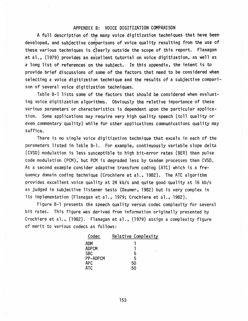
APPENDIX B: VOICE DIGITIZATION COMPARISONA full description of t~~ many voice digitization techniques that have been
developed, and subjective co~Iparisons of voice quality resulting from the use ofthese various techniques is diear1y outside the scope of this report. Flanagan
,~ ;J
et al., (1979) provides an extellent tutorial on voice digitization, as well asa long list of references on the subject. In this appendix, the intent is toprovide brief discussions of some of the factors that need to be considered whenselecting a voice digitization technique and the results of a subjective comparison of several voice digitizationtechniques.
Table B-1 lists some of the factors that should be considered when evaluating voice digitization algorithms. Obviously the relative importance of thesevarious parameters or cha.racteristics is dependent upon the particular application.' Some applications may require very high quality speech (toll quality oreven commentary quality) ~hile for other applications communications·quality maysuffice.
There is no single voice digitization technique that excels in each of theparameters listed in Table B-1. For example, continuously variable slope delta(CVSD) modulation is less susceptible to high bit-error rates (BER) than pulsecode mod.U1ati on (PCM), but PCM i s degraded 1ess by ta ndem processes than CVSD.As a second example consider adaptive transform coding (ATC) which ;'s a frequency domain coding technique (Crochiere et al., 1982). The ATC algorithmprovides excellent voice quality at 24 kb/s and quite good quality at 16 kb/sas judged in subjective listener tests (Daumer, 1982) but is very complex inits implementation (Flanagan et al., 1979; Crochiere et al., 1982).
Figure B-1 presents the speech quality versus codec complexity for severalbit rates. This figure was derived from information originally presented byCrochiere et al., (1982). Flanagan et al., (1979) assign a complexity figureof merit to various codecs as follows:
Codec---ADMADPCMSBCPP-ADPCMAPeATC
Relative Complexity1155
5050
153

U"1~
Table B-1. Evaluation Factors for Voice Digitization Algorithms
- Voice Quality (communications quality, toll quality, commentary quality,etc. )
o performance in the presence of background noise, bit errorrate, network losses echoes, etc.
o subjective measures: intelligibility, speaker recognition,voice naturalness, etc.
o objective measures
- Bit Rate
- Complexity of Hardware
- Cost (directly related to complexity)
- Tandem Capability
o asynchronous (A/D-D/A-A/D etc.)
o synchronous (A/D1-D1/D 2-D2/D, etc.)
- Delay (related to tandem encodings)
- Voice-Band Data and Signal Tone Encoding
- Dynamic Range
- Submultiple of 64 kb/s

--.I
U1U1
~+J-.-4
.......o::J
C
.cuOJOJC1.en
Excellent
Good
Fair
Poor
16 kb/sATe
'- ./
L SSUnsatisfactory , Complexi ty Factor ----?
Figure B=l. Speech quality versus codec complexity forseveral bit rates.
Table B-2 is a comparison of voice'digitization techniques that s~mmar;zes
the results obtained by Daumer (1982) of subjective listening tests. While thetesting was not exhaustive and some variation in the results could reasonably beexpected for a different set of listeners or test phrases, the results nevertheless are indicative of the type of performance that can be expected for the various low bit-rate voice coders. The test consisted of seven speech samples (bothmale and female) that were evaluated by 42 listeners thereby giving 292 votes foreach voice encoding technique. Each listener gave a rating from 5 through 1
(excellent, good, fair, poor, and unsatisfactory). The mean opinion score (MOS)
is simply the arithmetic mean of the ratings. The voice encoding techniquesevaluated included:
PCM (pulse code modulation)ATe (adaptive transform coding)APC (adaptive predictive coding)SBC (sub-band coding)CJF-ADPCM (Cummisky-Jayant-Flanagan adaptive differential
PCM), andPP-ADPCM (pitch predictive ADPCM)
Both single and tandem encodings were evaluated. The tandem encodings includedboth asynchronous conversions (A/D/A/D etc.) and synchronous conversions(A/Dl/D2/Dl/D2 etc.).
As can be seen from Table B-2 32 kb/s CJF-ADPCM was actually rated higher(but not significantly higher) than 64 kb/s PCM. High ratings were also given to24 kb/s APC and ATC for single encodings. The point is that for single encodings(which is the case for an all-digital network) substantial improvements in bandwidth utilization can be achieved without significantly degrading voice quality.For tandem encodings, there is little degradation in the voice quality for peMwhile the degradation for other voice encoders may be significant. As notedearlier the acceptability of the performance of a particular voice encoder isdependent upon the network requirements such as the expected number of tandemconversions and the voice quality required (communications quality, toll quality,etc.).
The reader is cautioned that the results in Table B-2 were arrived at without considering such realistic network characteristics as the allowable encodingdelay limitations and the existence of nonvoice signals such as voice band datain in-band signaling. Furthermore, the testing did not include modeling of
156

--'(J"'I
'-J
Table B-2. Comparison of Voice Digitization Techniques
Single Encoding Tandem Encoding Tandem Encoding(asynchronous) (synchronous)
Technique fvl0S Technique r~os Technique MOS
32 kb/s CJF-ADPCM 4.44 Single Conversion64 kb/s ~-255 peM 4.43 64 kb/s ~-255 peM 4.53Sources 4.39 32 kbjs CJF-ADPCM 4.3032 kb/s PP-ADPCM 4.27 16 kbjs APC 3.9824 kb/s APe 4.25 16 kb/s SSC 3. 1832 kbjs SSC 4.2524 kbjs ATC 4. 11 Double Conversions Double Conversions32 kbjs CJF-ADPCM 4.04 64 kbjs ~-255 PCM 4.5324 kb/s SSC 3.91 32 kbjs CJF-ADPCM 3.7016 kbjs APC 3.86 16 kbjs APC 3.62 16kbls APC 3.6824 kb/s PP-ADPCM 3.86 16 kbjs SSC 2.44 16 kb/s SBC 2.6516 kb/s ATC 3.7512 kbjs APC 3.42 Four Conversions Four Conversions16 kb/s PP-ADPCM 3.12 64 kbjs ~-255 PCM 4.3816 kbjs SSC 3.11 32 kbjs CJF-ADPCM 3.2032 kbjs ~-255 PCM 2.90 16 kbjs APe 2.74 16 kbjs APe 2.7324 kb/s CJF-ADPCM 2.52 16 kbjs SSC 1.86 16 kb/s SBC 2.0016 kbjs CJF-ADPCM 2.52
9.6 kbjs ATC 2.39 Eight Conversions Eight Conversions16 kbjs PCM 1.06 ~4 kb7s ~-255 PCM 4. 16
32 kb/s CJF-ADPCM 2.4016 kb/s APC 1. 74 16 kb/s APC 1.8916 kb/s SSC 1.41 16 kb/s sse 1.51
MOS = mean opinion score
network losses, noise, and echoes. The conclusions reached are for pa~ticular
implementations of the algorithm; other implementations may resul't in differentperformance evaluations.
Another po,int that should be emphasized is that voice performance alone is anecessary, but not sufficient, figure of merit for evaluating coder performance.If the network also carries voiceband data, the BER that results from passingsuch signals through the codec must be considered. Many codecs are optimallydesigned for the unique spectral and temporal characteristics of the speech signal. Voice band data BER performance for low bit-rate cadecs is degraded incomparison to the BER performance for the same data passing through a PCM coder.The higher voice band data rates such as 4,800 b/s are especially susceptible todegraded BER performance for some codecs. For such voice band data signals thecodec may have to be bypassed entirely.
Table B-3 summarizes the conclusions that may be drawn from Table B-2. Obviously more work must be done in evaluating all of the factors, listed in Table B-1for a particular set of network requirements. This is clearly outside the scopeof this appendix.
REFERENCESCrochiere, R., R. Cox, and J. Johnston (1982), Real-time speech coding, IEEE
Trans. on Comm. COM-3D, pp. 621-634, April.
Daumer,W. (1982), Subjective evaluation of several efficient speech coders, IEEETrans. on Comm. COM-3D, pp. 655-662, April.
Flanagan, J., M. Schroeder, B. Atal, R. Crochiere, N. Jayant, and J. Tribo1et(1979), Speech coding, IEEE Trans. on Comm. COM-27, pp. 710-737, April.
158

U'1\.0
Table B-3. Conclusions of Speech Coding
Single Encoding
- PCM is greatly degraded at bit rates lower than 64 kb/s
- PP-ADPCM performs better than CJF-ADPCM
- delays introduced by PCM and CJF-ADPCM are negligible
- complex coders introduce more delay e.g., vocoder driven ATC hasa delay of about 128 ms
- no coding techniques below 16 kb/s are acceptable for highquality telephone "service
Tandeming
64 kb/s PCM is degraded very little by tandem encoding
- SSC and APC perform poorly in either asynchronous or synchronoustandeming
- asynchronous tandem encoding is more of a problem thansynchronous tandem encoding (although the difference is smallfor sse and APC)
- as many as 4 tandem conversions are acceptable for 32 kb/sADPCM
General
- coder selection is highly dependent upon the application (voicequality required, expected number of tandem- conversions,economics, etc.)
- more work is needed

APPENDIX C: LINE CODESLine code compatibility is necessary to achieve ~;gital pipeline interopera
bility. Numerous types of line codes have been developed. Some line codes areself-synchronizing in that they always have a transition between levels during themiddle of a bit interval. Other considerations in choosing a line code are:
a. spectrum of the code and the available bandwidth,
b. noise and interference levels,
c. synchronization acquisition times, and
d. implementation requirements.
Figure C-l provides a comparison of the most commonly used line codes including non-return-to-zero (NRZ) which ;s used in both TRI-TAC and OCS equipment.Figure C-2 provides a detailed comparison of conditioned diphase (COP) which isused in some TRI-TAC equipment and regular diphase (Manchester) coding.
160

Unipolar (unbalanced coding)
Bi-0-L.. Transition at beginning of each symbol.Ones cause an additional transition at mid-symool.Zeroes have no mid-symbol transition.
Return to Zero (RZ)
Polar (balanced coding or NRZ-L)
Bipolar (alternate mark inversion·· AMI)
Miller Code. A one is represented by a transitionat mid-symbol. A zero results in no transitionexcept for two consecutive zeroes in which case thetransition takes place at the end of the first zero.
Coded Mark Inversion. Zeroes transition at midsymbol (from low level to high level). Alternateone's have alternate levels and do not transitionat mid-symbol.
Differentially encoded diphase. Ones cause achange of state (phase); zeroes do not.
Differentially encoded NRZ (NRZ-M). Ones cause achange of state (level); zeroes do not.
Diphase (Manchester coding or bi-0-M). Transitionsoccur in the middle of every symbol; ones transitionfrom a high level to a low level and zeroes transition from a low level to a high 1eve-l.
0 a 0 a 0, , , J, I
QJ 0 ·0I I I I
I J I I I I I
R::J R RI tI ,I I
I I
I I I, I I
~ I I I
I I I I
I I , I
I I ,I I
I
I'"
I I II I , . I I
1 R J t:JI
I I I I I.1 I I , I
f
I
I ,t I I
I I II I II I I tI I I I I I II
I Rj tRf1::Ji
I I I t It I I I
:=1 r+l I tJt I
Notes: NRZ-S (not shown) is the inve~se of NRZ-M. 81-0-5 (not shown) is the inverse of Bi-0-M.
Figure C-l. Comparison of commonly used line codes.
161
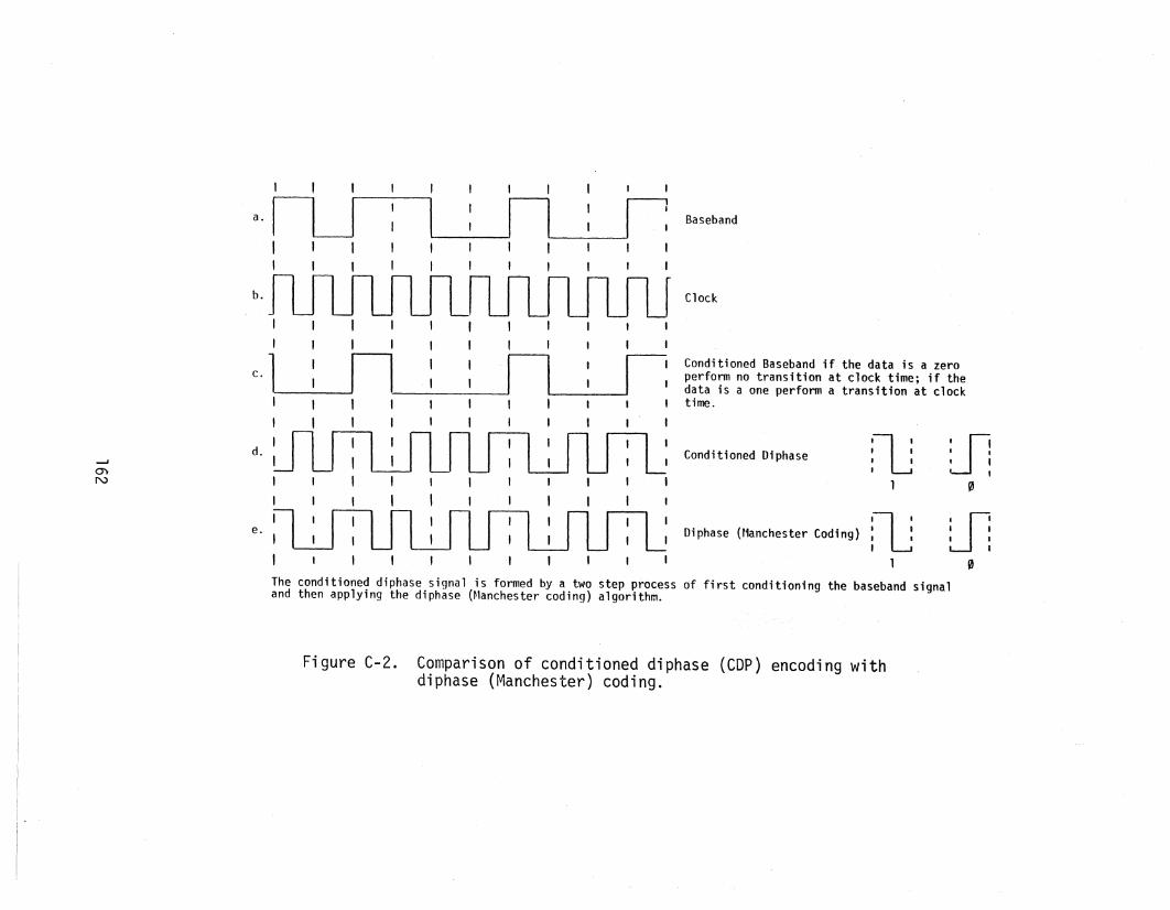
a.
b.
Baseband
Clock
Conditioned Baseband if the data is a zeroperform no transition at clock time; if thedata is a one perform a transition at clocktime.
--J
0)
N
II I I I I I I , , I I
c.LlJl : : n : r:I t I I I I I , ,
" I I I , t I I
d. I 11 rill I, I U I ~" I I I ,
I I I
:LJ:l' I r
e., I I
I , I
Conditioned Diphase
Oi phase (t1anches ter Codi ng)
'lJ' ,. ,,
'lJ·,, ., t
I
U!t t, ,•o
WII I, ,
I
"The conditioned diphase signal is formed by a two step process of first conditioning the baseband signaland then applying the diphase (Nanchester coding) algorithm.
Figure C-2. Comparison of conditioned diphase (COP) encoding withdiphase (Manchester) coding.

FORM NTIA-29(4-80)
u.s. DEPARTMENT OF COMMERCENAT'L. TELECOMMUNICATIONS AND INFORMATION ADMINISTRATION
BIBLIOGRAPHIC DATA SHEET
1. PUBLICATION NO.
NTIA Report 83-123
2. Gov't Accession No. 3. Recipient's Accession No.
4. TITLE AND SUBTITLE
Interoperability of the European DefenseCommunications System with TRI-Service TacticalCommunications
7. AUTHOR(S)
J. A. Hoffmeyer8. PERFORMING ORGANIZATION NAME AND ADDRESS
U.S. Department of CommerceNTIA/ITS325 BroadwayBoulder, Colorado 80303
11. Sponsoring Organization Name and Address
U.s. Army Communications Systems AgencyCCM-RDFt. Monmouth, New Jersey 07703
14. SUPPLEMENTARY NOTES
5. Publication Date
~1a.y 19836. Performing Organization Code
9. ProjecVTask/Work Unit No.
10. ContracVGrant No.
12. Type of Report a.nd Period Covered
13.
15. ABSTRACT (A 200-word or less factual sUlnmary of most significant information. If document includes a significant bibliography or literaturesurvey, mention it here.)
III This report discusses the different types of interoperability requirements,
summarizes several related research and development projects, and presentsalternatives for achieving interoperability between the Defense CommunicationsSystem and the TRI-Service Tactical Communications System. These alternativesare evaluated, and a preferred alternative is recommended. The report concludeswith brief tasking statements which are recommended to the u.S. Army Communications Systems Agency as the next steps in pursuing a research and developmentprogram for developing interoperability of the two systems at both the transmission subsystem level and at the end-to-end subscriber level. For transmission subsystem interoperability, emphasis is placed on the Digital EuropeanBackbone and Digital Radio and Multiplexer Acquisition portions of the EuropeanDCS.
16. Key Words (Alphabetical order, separated by semicolons)
Des; DEB; Digital European Backbone; digital radio; DRAMA; interoperability;multiplexer acquisition; TRI-TAC
17. AVAILABILITY STATEMENT
lXlX UNLIMITED.
o FOR OFFICIAL DISTRIBUTION.
18. Security Class. (This report)
Unclassified19. Security Class. (This page)
Unclassified
20. Number of pa.ges
18121. Price:
*U.S. Government Printing Office: 1980-678-495/529