Embed Size (px)
Citation preview
2012
YASEEN RAZA
NED University of Engineering
And Technology
INTERNSHIP REPORT
Yaseen Raza Ned University Of Engineering And Technology Page 2
INTERNSHIP
REPORT
SUBMITTED TO
MR. SHERAZ BHATTI
DEPUTY MANAGER CRM
SUBMITTED BY
YASEEN RAZA (MY-50)
NED UNIVERSITY OF ENGINEERING AND TECHNOLOGY
BATCH: 2009~2010
DURATION: 21ST MAY 2012 TO 30TH JUNE 2012
Yaseen Raza Ned University Of Engineering And Technology Page 3
ACKNOWLEDGMENT
Starting with the name of Allah who is the most merciful and
beneficent
My report work has accomplished under excellent guidance and
supervision of production and management team of
International Steels Limited, Karachi. I offer my heartiest
gratefulness to ISL team for its step to step guidance and close
supervision during the conduct of all the period of internship at
ISL.
No acknowledgement could ever adequately express my
obligations to my affectionate parents for their all inspirations
and guidance which always motivated us to carry ourselves
through the noblest ideas of life and solving all troubles and
boosted my moral to fly high to accomplish our goals.
I convey special thanks to my dear class adviser MR
IFTIKHAR AHMED CHANNA, NED University for his
excellent, efficient, accurate and reliable help to completion of
this internship as well as completed our report.
Yaseen Raza Ned University Of Engineering And Technology Page 4
I also convey special thanks to CRM plant production team
MR Yasir Sohail (SR.Manager CRM Operations)
MR Sheraz Bhatti (Deputy Manager CRM)
MR Imran Wasti (Deputy Manager CRM)
MR Danish Aftab (Asst.Manager CRM)
MR Abu Talha Kalimi (Asst.Manager CRM)
MR Umair baig (Deputy Manager CRM)
MR Shamsher Ali (Asst.Manager CRM)
MR Faraz Shafiq (Asst.Manager CRM)
MR Danish khan (Asst.Manager CRM)
MR Waseem (Operator Pickling)
MR Ayaz (Sr.shift Incharge Annealing)
MR Farhan (Operator Annealing)
MR Tasawar (Operator Rewinding)
MR Ahsan Munir (Shift Incharge Skin Pass)
Yaseen Raza Ned University Of Engineering And Technology Page 5
INDEX
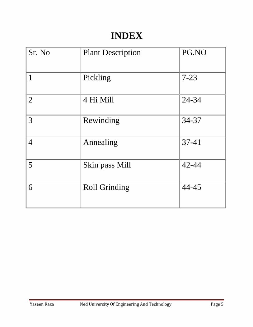
Sr. No Plant Description PG.NO
1 Pickling 7-23
2 4 Hi Mill 24-34
3 Rewinding 34-37
4 Annealing 37-41
5 Skin pass Mill 42-44
6 Roll Grinding 44-45
Yaseen Raza Ned University Of Engineering And Technology Page 6
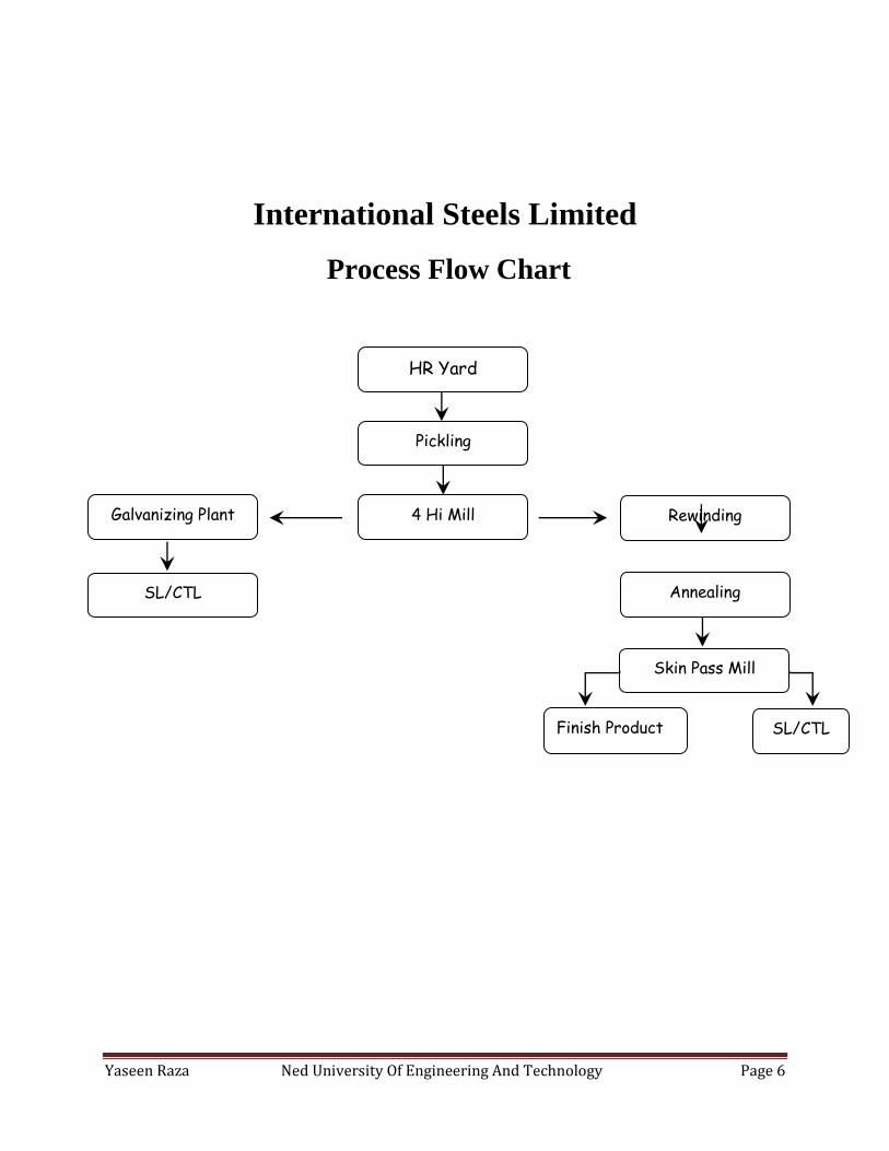
International Steels Limited
Process Flow Chart
HR Yard
Pickling
Rewinding 4 Hi Mill
Annealing
Galvanizing Plant
Skin Pass Mill
SL/CTL
SL/CTL
Finish Product
Yaseen Raza Ned University Of Engineering And Technology Page 7
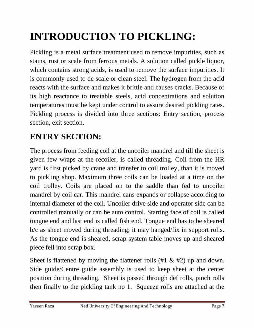
INTRODUCTION TO PICKLING:
Pickling is a metal surface treatment used to remove impurities, such as
stains, rust or scale from ferrous metals. A solution called pickle liquor,
which contains strong acids, is used to remove the surface impurities. It
is commonly used to de scale or clean steel. The hydrogen from the acid
reacts with the surface and makes it brittle and causes cracks. Because of
its high reactance to treatable steels, acid concentrations and solution
temperatures must be kept under control to assure desired pickling rates.
Pickling process is divided into three sections: Entry section, process
section, exit section.
ENTRY SECTION:
The process from feeding coil at the uncoiler mandrel and till the sheet is
given few wraps at the recoiler, is called threading. Coil from the HR
yard is first picked by crane and transfer to coil trolley, than it is moved
to pickling shop. Maximum three coils can be loaded at a time on the
coil trolley. Coils are placed on to the saddle than fed to uncoiler
mandrel by coil car. This mandrel cans expands or collapse according to
internal diameter of the coil. Uncoiler drive side and operator side can be
controlled manually or can be auto control. Starting face of coil is called
tongue end and last end is called fish end. Tongue end has to be sheared
b/c as sheet moved during threading; it may hanged/fix in support rolls.
As the tongue end is sheared, scrap system table moves up and sheared
piece fell into scrap box.
Sheet is flattened by moving the flattener rolls (#1 & #2) up and down.
Side guide/Centre guide assembly is used to keep sheet at the center
position during threading. Sheet is passed through def rolls, pinch rolls
then finally to the pickling tank no 1. Squeeze rolls are attached at the
Yaseen Raza Ned University Of Engineering And Technology Page 8
starting and end of each tank so that acid from 1 tank may not enter to
another tank.
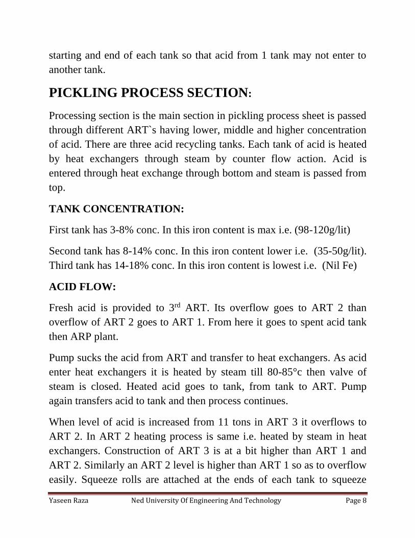
PICKLING PROCESS SECTION:
Processing section is the main section in pickling process sheet is passed
through different ART`s having lower, middle and higher concentration
of acid. There are three acid recycling tanks. Each tank of acid is heated
by heat exchangers through steam by counter flow action. Acid is
entered through heat exchange through bottom and steam is passed from
top.
TANK CONCENTRATION:
First tank has 3-8% conc. In this iron content is max i.e. (98-120g/lit)
Second tank has 8-14% conc. In this iron content lower i.e. (35-50g/lit).
Third tank has 14-18% conc. In this iron content is lowest i.e. (Nil Fe)
ACID FLOW:
Fresh acid is provided to 3rd ART. Its overflow goes to ART 2 than
overflow of ART 2 goes to ART 1. From here it goes to spent acid tank
then ARP plant.
Pump sucks the acid from ART and transfer to heat exchangers. As acid
enter heat exchangers it is heated by steam till 80-85°c then valve of
steam is closed. Heated acid goes to tank, from tank to ART. Pump
again transfers acid to tank and then process continues.
When level of acid is increased from 11 tons in ART 3 it overflows to
ART 2. In ART 2 heating process is same i.e. heated by steam in heat
exchangers. Construction of ART 3 is at a bit higher than ART 1 and
ART 2. Similarly an ART 2 level is higher than ART 1 so as to overflow
easily. Squeeze rolls are attached at the ends of each tank to squeeze
Yaseen Raza Ned University Of Engineering And Technology Page 9
acid, so that concentration of each tank may not get mixed. Since acid is
heated, fumes are generated. They may damage wall roofs and other
equipment so they have to be condensed.
SCRUBBER:
Scrubber is used to condense acid fumes. Each tank has yellow pipe
which is used to transfer fumes from tank to scrubber. Blower is used to
suck fumes from tanks and transfer to scrubber.
Scrubber has three floors each floor is filled inside with some fibers and
shower of water to convert these acid vapors into liquid. At a rate of
350Lit/hr, water is delivered to tower. Water is provided at the bottom,
pump suck this water and delivered it from the top. This acidic water is
than transfer to rinse conc. tank.
Certain fumes do not condense and moved to next chamber. Again water
is sprayed from the top, the water become acidic and this goes to
previous tank. Now remaining fumes are exhaust by a chimney by a fan
which blows away fumes from this section.
RINSE SECTION:
This section consists of series of chambers. Its function is to remove acid
droplets from sheet by spraying of water. First there is a rinse conc. tank.
In which water is sprayed by set of two nozzles. Water is provided from
scrubber section; water is pumped by pump and transferred to tank.
Again here it runs a cycle means acidic water is sprayed on sheet than
returns to tank, it goes on until as its condition become dead it is
delivered to ARP. There are 5 rinse tanks; in each there is a set of
nozzles and set of squeeze rolls at start and end of each section. Fresh
Yaseen Raza Ned University Of Engineering And Technology Page 10
water is provided to tank 5 its overflow goes to tank#4 and then to
tank#3, than to tank#2, than to tank#1.tank#2&1 have same acidic nature
or it may go to ARP. At end of tank#5 there is a pair of two squeeze
rolls.
PICKLING EXIT SECTION:
As sheet came out from rinse section, it may have some water droplets
at the edges. Edge knife blower is used to remove water from edges of
sheet then sheet is passed in hot dryer, in which heated air is used to dry
the sheet. Temperature is about 100-200°c in hot air dryer. Center guide
assembly is used to maintain sheet`s position at the centre.
After passing through pinch rolls and deflector rolls sheet is fed to
recoiler mandrel where it is fixed in recoiler mandrel. Mandrel collapse
then sheet is fixed in it and mandrel collapse again and given few wraps,
than tension is provided by tension units (#1 & #2). Line starts and
process goes on. Fish end/last end of sheet is sheared then coil car
moves in. pusher plate pushes the pickled coil on to coil car than it is
transferred to 4-HI plant.
ASSIGNMENTS OF PICKLING:
Following assignments were given by MR Danish Aftab & MR Imran
Wasti during our learning at pickling plant.
ASSIGNMENT # 1
Task: To analyze the problem and observe how it is removed
NAME OF THE PART:
The name of the given part is side guide assembly. It is also called center guide
assembly.
Yaseen Raza Ned University Of Engineering And Technology Page 11
FUNCTION:
The function of center guide assembly is to guide the sheet towards the
center.
It is only used during the charging of the sheet at the entrance and exit
during recoiling.
It consists of two balancing shafts at the bottom and a lead screw.
Two blocks move on the lead screw supported by the balancing rods.
On lead screw the threads are on opposite separated by a bush which is
mounted through dowel pins
Two vertical side rollers which support movement of the sheet
FAULT:
When sheet moved away from its path it pushed one guide roll too much that its
alignment became out. This led to non uniform movement of side guide rolls.
MAINTENANCE:
For maintenance assembly is turned upside down. Bush which separates the two
lead screw rods is uncoupled; alignment is adjusted and coupled again.
TIME REQUIREMENT:
Total approximated time for maintenance of center guide assembly is 2 hours.
ASSIGNMENT # 2
TASK:
“To study and observe installation of spent acid tank.”
I had been provided the diagram of tank and parts detail.
This tank was fabricated at Lahore then delivered to ISL. From main gate, it
was transferred to pickling entrance gate by truck.
lifter was used to lift the tank from hook
Accessories of tanks were also provided in a box.
Lifter put both of tanks & box on coiler & delivered inside the pickling shop.
Yaseen Raza Ned University Of Engineering And Technology Page 12
List of all accessories was provided from which all parts were verified.
Reducer FRD 80x mm was missing.
Tank was lifted from coiler & was placed on the floor in horizontal position
b/c if we lift it vertically it nozzle may get damaged.
It was then turned in vertical position then transferred to its place.
Now its position was adjusted so as to connect necessary accessories like
overflow pipe & drainage pipe etc.
ASSIGNMENT # 3
Pickling Entry section:
1. CRANE:
It is used to pick the coil from the coil yard. Its capacity is 30 tons
2. COIL CAR:
Pick coil is then transferred to the coil car. Maximum two coils can be placed on
coil car.
3. BABY COIL CAR:
It is used to transfer coils from the coil car to the saddle and also to uncoiler. It is
hydraulically operated. It has two buttons on the panel.
*Baby coil car (In/Out)
*Baby coil car (Lift/Lower)
4. SADDLE:
It is the place where extra coils are placed so that our operation remains
continuous.
Yaseen Raza Ned University Of Engineering And Technology Page 13
Description Of Entry Panel Buttons And
Their Functions:
5. UNCOILER:
It is used uncoil the coil for processing. It has four buttons on the panel for
controlling it.
*Uncoiler (Operator side In/Out)
*Uncoiler (Driver side In/Out)
*Uncoiler (both side in and both side out)
6. UNCOILER MANDREL:
It is that part where the coil is attached. It has two buttons on the panel,
*One for the expansion of the mandrel
* Other for mandrel collapse.
7. UNCOILER HOLDS DOWN:
It is that part, which is used to hold the sheet so that it may not fall backward
because of its weight. One button on the panel is used for upward or downward
movement.
*uncoiler hold down (up/down)
8. PEELER TABLE:
Peeler table is used to make the face of the sheet and push the sheets towards pinch
rolls. It also acts as support. Two buttons are placed (up/down) and (Lift/lower).
*Peeler table (up/down)
*Peeler table (lift/lower)
Yaseen Raza Ned University Of Engineering And Technology Page 14
9. FLATTENER PINCH ROLLS:
They are used to hold the sheet and remove edge defects. Also have two buttons.
*Flattener cum pinch rolls (up/down)
*Flattener cum pinch rolls (forward/reverse)
10. FLATTENER:
Flattener rolls are used to flat the face of the sheet and there are 5 rollers for
flattening, 3 on downward side and 2 on upward side. Two upward sides one can
move only and individually as well.
*Flattener rolls#1 (up/down)
*Flattener rolls#2 (up/down)
*Quick lift for quick movement of both in any emergency.
*Flattener (increase/decrease) this button is used to increase or decrease the speed
of the rolls.
11. CENTER GUIDE (UNCOILER):
When the sheet is out, it is used to place the sheet on center, it can be manually be
operated and automatically as well.
*Center guide (auto/manual)
12. SHEAR CUTTER:
To cut the face of the sheet, this is treated as scrap. One button named entry shear
mode safe has two options (manual/cut). For cut only there is one more button
named cut which we press it will cut the sheet. Cutter movement is not operator’s
control. For manual only there is one more button named entry
* shear (up/down) which controls the movement of the shear cutter.
Yaseen Raza Ned University Of Engineering And Technology Page 15
13. SCRAP SYSTEM TABLE:
It is used to place the table upward so that scrap which is cut through shear cutter
does not go forward on the line.
*Scrap system table (up/down)
14. CENTER GUIDE ASSEMBLY:
When sheet is out of center then it is used to place the on center.
*Side guide (in/out)
15. EDGE TRIMMING:
If the requirement is of less sheet width then we use edge trimmer to cut the
desired sheet width. Two buttons are used on the panel.
* Edge trimmer (up/down) *Edge trimmer (forward/reverse)
16. EDGE TRIMMER HOLD DOWN:
It is used to hold the sheet when trimming is performed.
*Edge trimmer hold down (up/down)
17. SCRAP WINDER:
It is used to wind the scrap which is cut through edge trimmer.
*Driver side (in/out)
*Operator side (in/out)
Yaseen Raza Ned University Of Engineering And Technology Page 16
ASSIGNMENT # 4
Pickling Process Section:
Processing section is the main section in pickling process sheet is passed
through different ART`s having lower, middle and higher concentration of
acid.
There are three acid recycling tanks. Each tank is heated by regenerates
through acid in stem by counter flow action.
Acid is entered through heat exchange through bottom and steam is passed
from top.
First tank has 3-8% conc. In this iron content is max i.e. (98-120g/lit)
Second tank has 8-14% conc. In this iron content is max i.e. (35-50g/lit)
Third tank has 14-18% conc. In this iron content is max i.e. (Nil Fe)
Fresh acid is providing to 3rd ART.
Its flow overflow goes to ART 2 than overflow of ART 2 is gone to ART 1.
From here it goes to spent acid tank then ARP.
Pump sucks the acid from ART than to HX. As acid enter HX it is heated by
steam till 80-85 then valve of steam is closed. Acid goes to tank from tank to
ART then suck by pump again transfer to tank and then process kept going
on.
When level of acid is increased from 11 tons in ART 3 it is overflow to ART
2. In ART 2 heating process is same i.e. heated by steam in HX.
ART 3 is at a bit higher than ART 1 and ART 2.
An ART 2 level is higher than ART 1 so as to overflow easily.
Squeeze nuts are attached at the ends of each tank to squeeze at acid. So that
conc. of each tank may not get mixed.
Since acid is heated fumes are generated.
4 tons of acid is flowing in pipes. They may damage wall roofs and other
equipment so they have to be condensed.
Yaseen Raza Ned University Of Engineering And Technology Page 17
Scrubber:
Scrubber is used to condense acid fumes each tank has yellow pipe which is
used to transfer fumes from tank to scrubber. Blower is used to suck fumes
from tanks and transfer to scrubber.
Scrubber has three floors each floor is filled inside with some fibers and
shower of water to convert these acid vapors into liquid. 350L/hr water is
delivered to tower.
Water is provided at the bottom pump suck this water and shivered it from
the top.
This acidic water is than transfer to rinse conc. tank. Certain fumes do not
condense and moved to next chamber again water is sprayed from the top,
the water become acidic and this goes to tank. Now remaining fumes are
exhaust by exhaust by a chimney.
A fan is used to blown away fumes from this section.
Rinse Section:
This section consists of series of chambers. Its function is to remove acid
droplets from sheet by spraying of water.
First there is a rinse conc. tank. In which water is sprayed by set of two
nozzles.
Water is provided from scrubber section; water is pumped by pump and
transferred to tank. Again here it runs a cycle as its condition become dead it
is delivered to ARP.
After this the 5 rinse tanks. Each there is a set of nozzle and set of squeeze
rolls at start and end of each section. Fresh water is provided to tank 5 its
overflow goes to 4 and then 3, 2, 1. 2, 1 has same acidic nature or it may go
to ARP.
At end of set 5 there are two squeeze rolls then there is an edge knife blower
which removes water from edges of sheet then it comes in hot dryer.
Yaseen Raza Ned University Of Engineering And Technology Page 18
ASSIGNMENT # 5
EXIT BUTTONS DESCRIPTION:
(NOTE; * shows button)
1. MAIN HYDRAULIC PUMP:
*Main hydraulic pump is first on because all hydraulic system is activated through
this button.
2. FEED MODE BUTTON:
*Feed mode button is pressed when sheet has passed through the center guide
assembly.
3. EDGE KNIFE BLOWER:
This is used to clear the remaining water on the edges of the sheets so that sheet
may not become rusty again. It has one button.
*Edge blower (on/off)
4. HOT AIR DRYER:
When the sheet comes out of the rinse tank it may be wet, to remove the water
spread on the sheet it is dried through air in hot air dryer. It has one button. *Hot
dryer (on/off)
5. CENTER GUIDE #1
When the sheet came out from hot dryer, it is used to place the sheet on center.
6. PINCH ROLLS:
They are used to hold the sheet and remove edge defects. Also have two buttons.
*Pinch rolls (up/down) *Pinch rolls (forward/reverse)
Yaseen Raza Ned University Of Engineering And Technology Page 19
8. EDGE GUIDE PUMP:
To remain sheet on the center edge guide pump must be on so that recoiler can
move adjust the sheet. It has one button.
*Edge guide pump (on/off)
9. APRON TABLE:
Apron table is used to support the sheet when it is recoiled. Two buttons are
*placed for (up/down) and (lift/lower).
10. DB SUPPORT:
To support the recoiler mandrel
11. RECOILER LUBRICATION:
To provide lubrication during process:
12. RECOILER MANDREL:
It is that part where the coil is recoiled. It has two buttons on the panel, one for the
expansion of the mandrel and other for mandrel collapse.
13. LINE BUTTON:
It is activated when the sheet is fixed into the recoiler the end of threading. * Line
(on/off)
14. TENSION UNITS BUTTON:
To provide tension in the sheet when it is recoiled it must have passed through the
tension units. These units also flatten the sheet. There are two tension units at the
exit.
*Tension unit#1(up/down)
*Tension unit#2(up/down)
Yaseen Raza Ned University Of Engineering And Technology Page 20
15. SHEAR CUTTER:
To cut the end of the sheet which is treated as scrap. One button named exit shear
mode safe has two options (manual/cut). For cut only there is one more button
named cut which we press it will cut the sheet. Cutter movement is in operator’s
control. For manual only there is one more button named entry shear (up/down)
which controls the movement of the shear cutter.
16. SCRAP SYSTEM TABLE:
It is used to place the table upward so that scraps which are cut through shear
cutter do not go forward on the line. *Scrap system table (up/down).
17. CENTER GUIDE #2:
When sheet is out of center then it is used to place the on center.
*Side guide (in/out)
19. PUSHER PLATE:
When sheet is completely recoiled it is used to remove the coil from the mandrel.
*Pusher plate (in/out)
20. COIL CAR PUMP:
This pump must be on so that coil car can move. It has one button
*Coil car pump (on/off)
21. COIL CAR:
Coil car is used to transfer coils from the recoiler to the saddle. It is hydraulically
operated. It has two buttons on the panel.
*Baby coil car (In/Out)
*Baby coil car (Lift/Lower)
Yaseen Raza Ned University Of Engineering And Technology Page 21
ASSIGNMENT # 6 In pickling three is one main hydraulic pump which provides hydraulic power to
all hydraulic pipes. Following information is about main hydraulic pump.
GENERAL KNOWLEDGE:
Max working pressure 105 bar
Operating temperature min=40°c and max=55°c
Working fluid=mineral oil.
Power source ac 415v-50Hz and operate on 3 phase.
All pipes joint with tag welding only.
ABOUT:
There are two induction motors in main hydraulic pump.
One motor work and other motor for safety if some problem occur then we
use second motor to avoid down time.
In main hydraulic machine there is a filter which also has silica jell for
absorbing moisture.
Some times due to leakage and other factor the quantity of hydraulic oil will
be low then we add hydraulic oil in machine.
Hydro motors are more powerful then electric motors and in speed electric
motors more than hydraulic.
WORKING:
The main hydraulic pump provide power to all hydraulic cylinders for
moving many machines
There are two pipes in every machine which proceed by hydraulic one are in
let and other is out let.
In let for in the pressure of hydraulic oil and out let for return to the machine
USES:
Baby coil car moves due to hydraulic power.
Squeeze roll also move due to hydraulic.
UN coiler also moves due to hydraulic.
Yaseen Raza Ned University Of Engineering And Technology Page 22
Re coiler also move due to hydraulic.
Peeler table also move due to hydraulic system
ASSIGNMENT # 7
TASK: The quality of sheet is not proper and acid is not complete wash away from
sheet, so inspect the nozzle.
BASIC KNOWLEDGE:
When sheet comes from acid tank the acid wash from sheet with water.
The water shower through nozzles.
There are one concentration tank and five cascade tanks.
In concentration tank there are 32 nozzles while in each cascade tank there
are 16 nozzles.
The water pass supply of concentration tank is separate while water supply
in 5 cascade tank and then its flow pass in fourth then 3rd till 1st cascade tank
INSPECTION AND MAINTAINANCE:
First main steam wall done off.
Then check the flow of water from nozzles also check the damage of nozzles
If flow of water is not properly then take out headers and set the direction of
nozzles.
If any nozzle break or have crack then change nozzle.
The important thing is when you fit the nozzle you should not fit it much
tight it chance to break or crack.
The error comes in nozzles generally when sheet strike with nozzle.
Yaseen Raza Ned University Of Engineering And Technology Page 23
ASSIGNMENT # 8
Manometer:
DEFINATION:
Pressure measuring devices using liquid columns in vertical or inclined
tubes are called manometers.
A manometer is referred to a pressure measuring instrument, usually limited
to measuring pressures near to atmospheric. The term manometer is often
used to refer specifically to liquid column hydrostatic instruments.
PRINCIPLE:
The level of the liquid being determined by the fluid pressure and the height
of the liquid being indicated on a scale.
Pressure is exerted on one end of a U-shaped tube partially filled with liquid;
the liquid is displaced upwards on the other side of the tube by a distance
proportional to the pressure difference on each side of the tube.
Manometers are cheap, simple, and reliable. They are widely used,
particularly in undergraduate fluid mechanical laboratories.
The most serious drawback of a manometer, is that is has a very poor
temporal response. A manometer can not pick up rapid changes in pressure.
As a result, they are best suited to applications where steady-state pressure is
being measured.
Yaseen Raza Ned University Of Engineering And Technology Page 24
4 HI COLD ROLLING MILL:
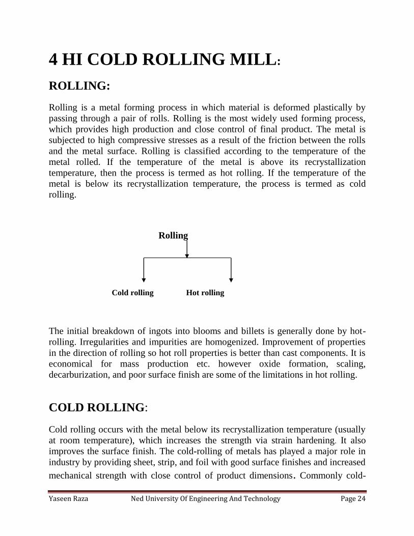
ROLLING:
Rolling is a metal forming process in which material is deformed plastically by
passing through a pair of rolls. Rolling is the most widely used forming process,
which provides high production and close control of final product. The metal is
subjected to high compressive stresses as a result of the friction between the rolls
and the metal surface. Rolling is classified according to the temperature of the
metal rolled. If the temperature of the metal is above its recrystallization
temperature, then the process is termed as hot rolling. If the temperature of the
metal is below its recrystallization temperature, the process is termed as cold
rolling.
Rolling
Cold rolling Hot rolling
The initial breakdown of ingots into blooms and billets is generally done by hot-
rolling. Irregularities and impurities are homogenized. Improvement of properties
in the direction of rolling so hot roll properties is better than cast components. It is
economical for mass production etc. however oxide formation, scaling,
decarburization, and poor surface finish are some of the limitations in hot rolling.
COLD ROLLING:
Cold rolling occurs with the metal below its recrystallization temperature (usually
at room temperature), which increases the strength via strain hardening. It also
improves the surface finish. The cold-rolling of metals has played a major role in
industry by providing sheet, strip, and foil with good surface finishes and increased
mechanical strength with close control of product dimensions. Commonly cold-
Yaseen Raza Ned University Of Engineering And Technology Page 25
rolled products include sheets, strips, bars, and rods; these products are usually
smaller than the same products that are hot rolled. Because of the smaller size of
the work pieces and their greater strength, as compared to hot rolled stock, four-
high or cluster mills are used. Cold rolling cannot reduce the thickness of a work
piece as much as hot rolling in a single pass.
REDUCTION IN COLD ROLLING:
The total reduction achieved by cold-rolling generally will vary from about 50 to
90%. The reduction in each stand should be distributed uniformly without falling
much below the maximum reduction for each pass. Generally the lowest
percentage reduction is taken place in the last pass to permit better control of
flatness, gage, and surface finish. Cold-rolled sheets and strips come in various
conditions: full-hard, half-hard, quarter-hard, and skin-rolled. Full-hard rolling
reduces the thickness by 50%, while the others involve less of a reduction.
Cold rolling mills reduce hot rolled coils to lighter thicknesses; establish uniform
hardness, accurate dimensional tolerances and the required surface finish
PROCESS:
Cold rolling is performed by unwinding the hot roll coil and passing the strip
through pairs of horizontal rolls or mill "stands". Coils are received from pickling
and placed in the stock area, then transferred to POR (Pay off Reel) mandrel. The
process from feeding coils at the POR mandrel and till the sheet is given few wraps
at the recoiler is called threading.
Reduction is not carried out completely in a single pass; however in each pass
reduction occurs to a certain limit. A reduction of max 38% is possible in first pass
then reduction rate decreases in upcoming passes. The number of passes depend on
the thickness of HR sheet, higher the thickness; greater will be the number of
passes required.
Yaseen Raza Ned University Of Engineering And Technology Page 26
EMULSION:
Emulsion, which is a mixture of soluble oil and water, is used as a roll coolant,
lubricant and cleaner. Its composition is 2-4% oil and remaining is water.
Emulsions contain both a dispersed and a continuous phase; the boundary between
these phases is called the interface. Emulsions tend to have a cloudy appearance
because the many phase interfaces scatter light as it passes through the emulsion.
Emulsions appear white when all light is scattered equally. Used emulsion goes to
emulsion tank, where it is cleaned. Emulsion tank has two parts; dirty section and
clean section. Used emulsion is filtered, cleaned and then came back to mill again.
Temperature of emulsion is about 50°c. Temperature at rolling mill is about 200°c
due to friction and plastic deformation. Therefore, we use emulsion of 50°c to
avoid chilling of sheet. Two pumps are used for roll bite and roll coolant. Roll bite
is contact area between work rolls and roll coolant is area between work rolls and
backup rolls.
The water used in emulsion is demineralized water. The minerals present in water
are normally calcium, magnesium, sodium, alkalinity, chlorides, sulfates, nitrates,
and silica can harm pipes, assemblies etc by causing corrosion, scale building,
spotting etc.
Yaseen Raza Ned University Of Engineering And Technology Page 27
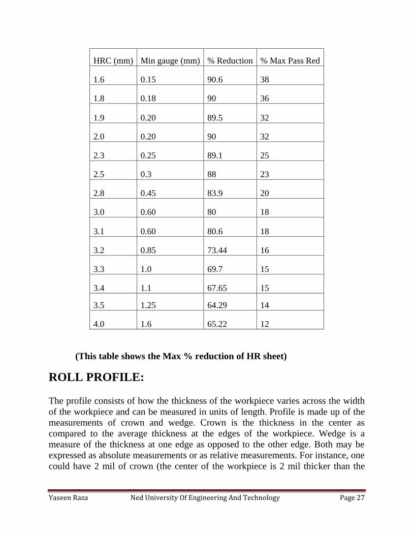
HRC (mm) Min gauge (mm) % Reduction % Max Pass Red
1.6 0.15 90.6 38
1.8 0.18 90 36
1.9 0.20 89.5 32
2.0 0.20 90 32
2.3 0.25 89.1 25
2.5 0.3 88 23
2.8 0.45 83.9 20
3.0 0.60 80 18
3.1 0.60 80.6 18
3.2 0.85 73.44 16
3.3 1.0 69.7 15
3.4 1.1 67.65 15
3.5 1.25 64.29 14
4.0 1.6 65.22 12
(This table shows the Max % reduction of HR sheet)
ROLL PROFILE:
The profile consists of how the thickness of the workpiece varies across the width
of the workpiece and can be measured in units of length. Profile is made up of the
measurements of crown and wedge. Crown is the thickness in the center as
compared to the average thickness at the edges of the workpiece. Wedge is a
measure of the thickness at one edge as opposed to the other edge. Both may be
expressed as absolute measurements or as relative measurements. For instance, one
could have 2 mil of crown (the center of the workpiece is 2 mil thicker than the
Yaseen Raza Ned University Of Engineering And Technology Page 28
edges), or one could have 2% crown (the center of the workpiece is 2% thicker
than the edges).
4 HI ROLLS:
4 Hi Rolling Mill consist of four rolls, two work rolls which perform reduction and
two backup rolls. Backup rolls are intended to provide rigid support required by the
working rolls to prevent bending under the rolling load. Rolling balance system is
use to ensure that the upper work and back up rolls are maintain in proper position
relative to lower rolls. AGC (Automatic Gap Control) controls the roll gap. In Roll
changing process a unit designed to attach to the neck of the roll to be removed
from or inserted into the mill.
THICKNESS MEASUREMENT:
Thickness is measured by x-ray gauges and reading is provided to computer. Initial
and final thicknesses at the entry and exit of each pass are fed in computer.
Thickness at exit of first pass became the entry thickness of second pass, similarly
for each pass. A graph continuously shows the variation in thickness at entry and
exit. This thickness variation gives feedback to AGC which controls the roll gap.
The arc of the contact is circular and the coefficient of friction is constant at all
points on the arc of contact. The elastic deformation of the sheet is negligible in
comparison with the plastic deformation.
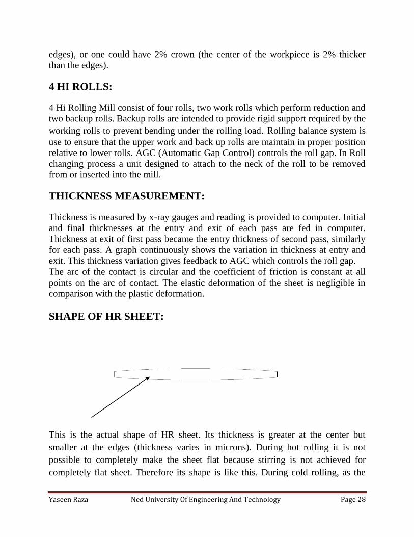
SHAPE OF HR SHEET:
This is the actual shape of HR sheet. Its thickness is greater at the center but
smaller at the edges (thickness varies in microns). During hot rolling it is not
possible to completely make the sheet flat because stirring is not achieved for
completely flat sheet. Therefore its shape is like this. During cold rolling, as the
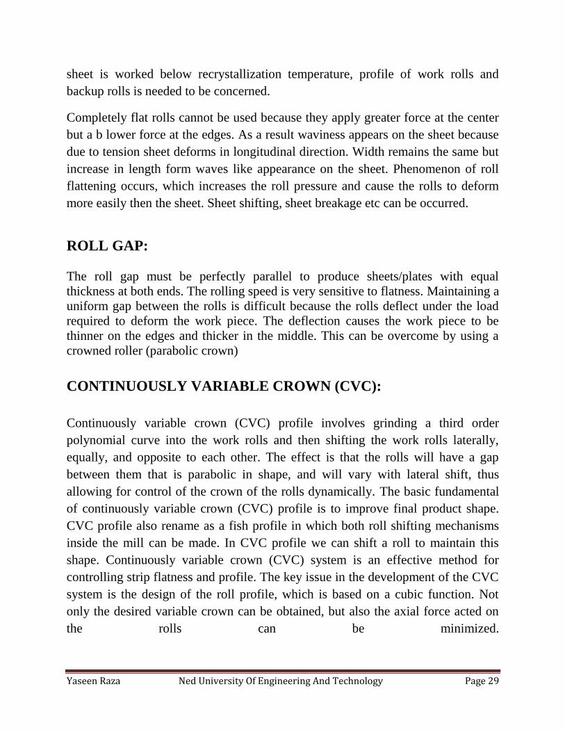
Yaseen Raza Ned University Of Engineering And Technology Page 29
sheet is worked below recrystallization temperature, profile of work rolls and
backup rolls is needed to be concerned.
Completely flat rolls cannot be used because they apply greater force at the center
but a b lower force at the edges. As a result waviness appears on the sheet because
due to tension sheet deforms in longitudinal direction. Width remains the same but
increase in length form waves like appearance on the sheet. Phenomenon of roll
flattening occurs, which increases the roll pressure and cause the rolls to deform
more easily then the sheet. Sheet shifting, sheet breakage etc can be occurred.
ROLL GAP:
The roll gap must be perfectly parallel to produce sheets/plates with equal
thickness at both ends. The rolling speed is very sensitive to flatness. Maintaining a
uniform gap between the rolls is difficult because the rolls deflect under the load
required to deform the work piece. The deflection causes the work piece to be
thinner on the edges and thicker in the middle. This can be overcome by using a
crowned roller (parabolic crown)
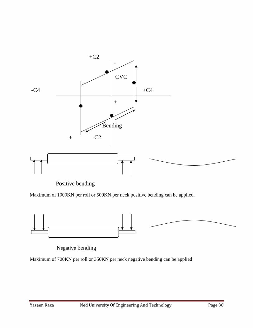
CONTINUOUSLY VARIABLE CROWN (CVC):
Continuously variable crown (CVC) profile involves grinding a third order
polynomial curve into the work rolls and then shifting the work rolls laterally,
equally, and opposite to each other. The effect is that the rolls will have a gap
between them that is parabolic in shape, and will vary with lateral shift, thus
allowing for control of the crown of the rolls dynamically. The basic fundamental
of continuously variable crown (CVC) profile is to improve final product shape.
CVC profile also rename as a fish profile in which both roll shifting mechanisms
inside the mill can be made. In CVC profile we can shift a roll to maintain this
shape. Continuously variable crown (CVC) system is an effective method for
controlling strip flatness and profile. The key issue in the development of the CVC
system is the design of the roll profile, which is based on a cubic function. Not
only the desired variable crown can be obtained, but also the axial force acted on
the rolls can be minimized.
Yaseen Raza Ned University Of Engineering And Technology Page 30
+C2
-
CVC
-C4 +C4
+
-
Bending
+ -C2
Positive bending
Maximum of 1000KN per roll or 500KN per neck positive bending can be applied.
Negative bending
Maximum of 700KN per roll or 350KN per neck negative bending can be applied
Yaseen Raza Ned University Of Engineering And Technology Page 31
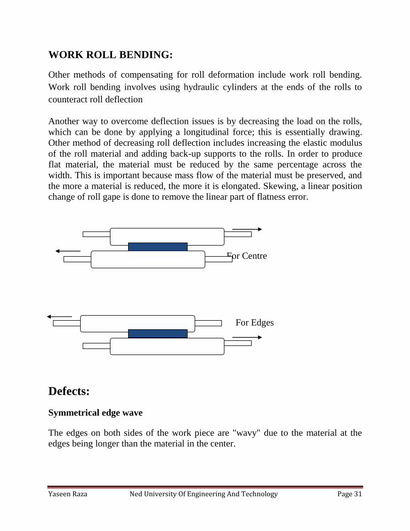
WORK ROLL BENDING:
Other methods of compensating for roll deformation include work roll bending.
Work roll bending involves using hydraulic cylinders at the ends of the rolls to
counteract roll deflection
Another way to overcome deflection issues is by decreasing the load on the rolls,
which can be done by applying a longitudinal force; this is essentially drawing.
Other method of decreasing roll deflection includes increasing the elastic modulus
of the roll material and adding back-up supports to the rolls. In order to produce
flat material, the material must be reduced by the same percentage across the
width. This is important because mass flow of the material must be preserved, and
the more a material is reduced, the more it is elongated. Skewing, a linear position
change of roll gape is done to remove the linear part of flatness error.
For Centre
For Edges
Defects:
Symmetrical edge wave
The edges on both sides of the work piece are "wavy" due to the material at the
edges being longer than the material in the center.
Yaseen Raza Ned University Of Engineering And Technology Page 32
Asymmetrical edge wave
One edge is "wavy" due to the material at one side being longer than the other side.
Center buckle
The center of the strip is "wavy" due to the strip in the center being longer than the
strip at the edges.
ASSIGNMENTS:
Following assignments were given to us at the 4 hi rolling mill.
Assignment # 1
To find out the number of wraps in a coil:
GIVEN:
Internal dia of coil = 610mm
Outer dia of coil = 2500mm
Thickness = 2.0mm
No of wraps =?
SOLUTION:
NO OF WRAPS = (O.D-I.D)/2
= (2500-610)/2
= 945
NO OF WRAPS = 945/2
= 473 wraps
Yaseen Raza Ned University Of Engineering And Technology Page 33
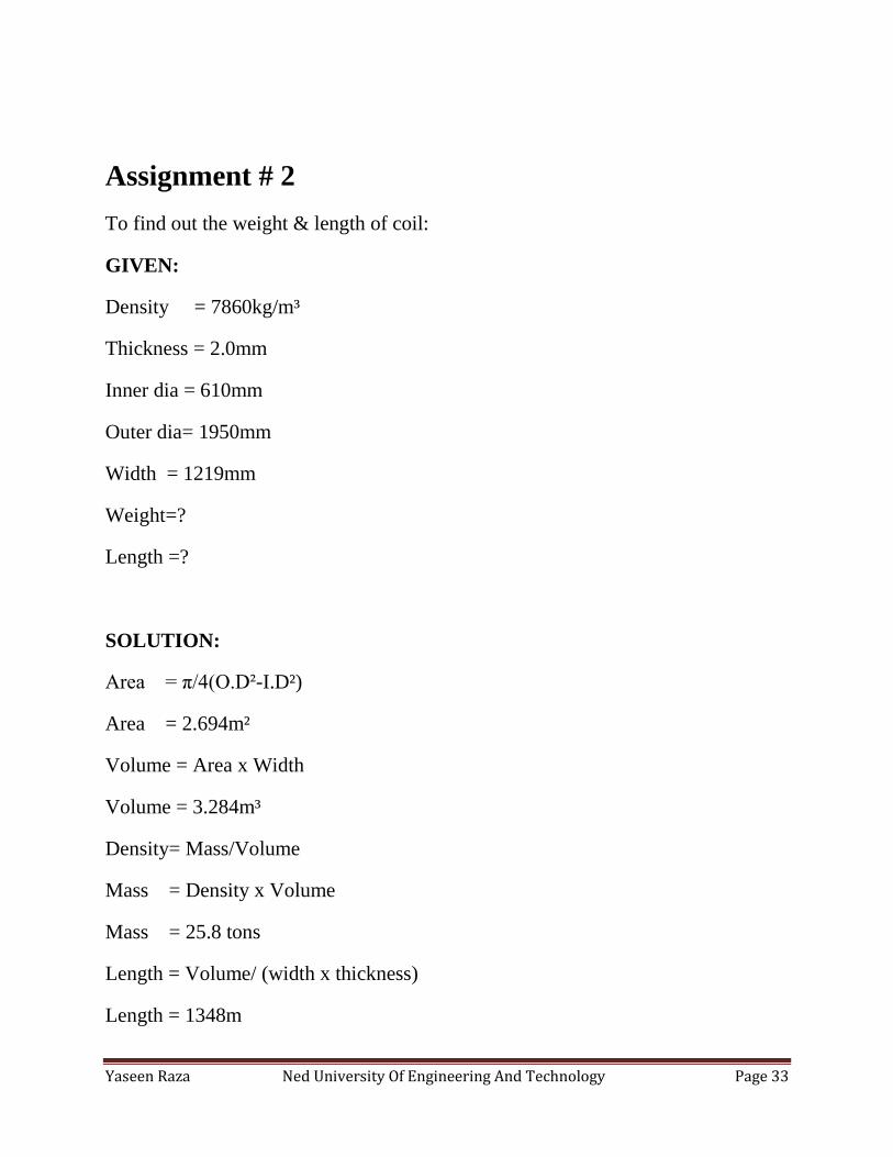
Assignment # 2
To find out the weight & length of coil:
GIVEN:
Density = 7860kg/m³
Thickness = 2.0mm
Inner dia = 610mm
Outer dia= 1950mm
Width = 1219mm
Weight=?
Length =?
SOLUTION:
Area = π/4(O.D²-I.D²)
Area = 2.694m²
Volume = Area x Width
Volume = 3.284m³
Density= Mass/Volume
Mass = Density x Volume
Mass = 25.8 tons
Length = Volume/ (width x thickness)
Length = 1348m
Yaseen Raza Ned University Of Engineering And Technology Page 34
Assignment # 3
We were given assignment to calculate the thickness of two different samples of
sheet and generate a graph to observe the variation of thickness across the width of
sheet. We also learned the CVC profile calculation. Working of this assignment
has been attached.
Assignment # 4
In order to understand the microstructure of steel sheet during the complete
process of cold rolling, we were given task to perform the microscopy of different
samples of sheet.
These samples were following:
1) After SPM (0.828mm) 2) After 4hi (1.085mm)
3) After 4 hi2 (1.173mm) 4) Pickled HR (2.156mm)
5) HR (2.240mm) 6) After annealing (0.196mm)
Other than these samples, three more samples were provided. We went
to NED to perform microscopy. After performing microscopy, we
provide them the microstructure images etc.
REWINDING:
Coils are wound at high tension at 4 hi mill (6000kgf). The reason for
rewinding is that if coils are wind at high tension they may stick together
during annealing and annealing would not be achieved properly. At
Yaseen Raza Ned University Of Engineering And Technology Page 35
rewinding shop their tension is released and winds at lower tension of
about 2150kgf. Therefore their tension is released at rewinding section.
TAPER TENSION:
In winding systems, decreasing the tension while the winder radius
increases is called taper tension, this can make the inner of the winder
tighten and the outer of the winder loosen, thus avoid slipping.
It is therefore necessary to analyze the relationship between taper
tension in winding section and internal stress distribution within center-
wound roll to prevent winding failure (starring, buckling, telescoping
etc).
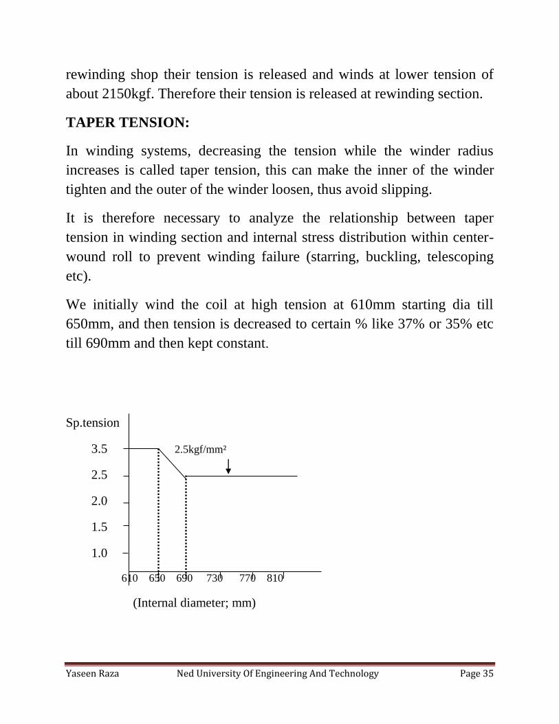
We initially wind the coil at high tension at 610mm starting dia till
650mm, and then tension is decreased to certain % like 37% or 35% etc
till 690mm and then kept constant.
Sp.tension
3.5 2.5kgf/mm²
2.5
2.0
1.5
1.0
610 650 690 730 770 810
(Internal diameter; mm)
Yaseen Raza Ned University Of Engineering And Technology Page 36
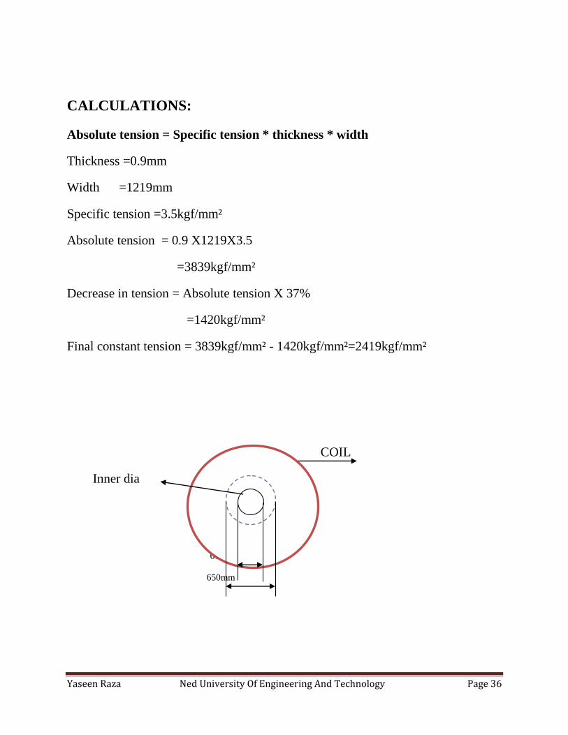
CALCULATIONS:
Absolute tension = Specific tension * thickness * width
Thickness =0.9mm
Width =1219mm
Specific tension =3.5kgf/mm²
Absolute tension = 0.9 X1219X3.5
=3839kgf/mm²
Decrease in tension = Absolute tension X 37%
=1420kgf/mm²
Final constant tension = 3839kgf/mm² - 1420kgf/mm²=2419kgf/mm²
COIL
Inner dia
610mm
650mm
Yaseen Raza Ned University Of Engineering And Technology Page 37
REWINDING PROCESS:
Coil is first loaded from stock area and placed on the saddle then fed to uncoiler
mandrel. The process from feeding coil at the uncoiler mandrel and till the sheet is
given few wraps at the recoiler, is called threading. Centre is adjusted for the coil
and then threading is carried out. Coil`s face bending and shearing is made if
required. Recoiler mandrel is collapse and sheet is fixed in it and mandrel is
expanded. Sheet is given few wraps on uncoiler and then tension is provided
3800kgf initially to give a tighten core.
The tension is decreased to certain level and rest of the coil is wind at that constant
tension. CPC cameras are placed at the entry just after the apron table for
managing the centre position of the sheet. Threading is made manually than rest of
the line runs on auto process. Line speed should be control b/c wraps may become
out during rewinding which is not desirable. Wraps out may get bend during
annealing and thus increase the chance of scrap.
CORE OUT PROBLEM:
We also observed a problem about wrap out during rewinding. Wraps of coil
became out suddenly after half of the coil had winded. Rewinding machine was
running on center mode properly but not accurately on the auto mode. First CPC
cameras were checked, and replaced by new ones but still problem wasn`t solved.
Actual problem was with the gear box slider which was not functioning properly.
As the center of sheet became out it moves back but came forward slowly due to
friction. Gear box was lubricated and minimized the problem.
ANNEALING:
Annealing is a heat treatment process in which Controlled heating and controlled
cooling is carried out. It is a process that produces desire conditions by heating to
above the critical temperature, maintaining a suitable temperature, and then
Yaseen Raza Ned University Of Engineering And Technology Page 38
cooling. Annealing is a heat treatment process in which is used to induce ductility,
soften material, relieve internal stresses, refine the structure by making it
homogeneous, and improve cold working properties.
DIFFUSION IN ANNEALING:
Diffusion phenomenon occurs in annealing. The movement of atoms has the effect
of redistributing and destroying the dislocations in metals. This alteration in
dislocations allows metals to deform more easily, so increases their ductility. On
heating at specific temperature and cooling it is possible to bring the atom at the
right lattice site and new grain growth can improve the mechanical properties
OBSERVATION & LEARNING:
Currently 3Cooling Bells and 2 Heating Bells are operating. Coil is first received
from rewinding to tilter, where its face is changed (from axial to longitudinal).
Then it is feed to stock area. A strip is tightened after two or three wraps so in
rewinding (so as to hold the core raps tight together). Before loading the base
check the base fan, sealing rubber. Clean the work base as it contains some
particles of emulsion, they may cause problems during annealing like make the
surface appear dull, and they may stick on the coils during flow of gas.
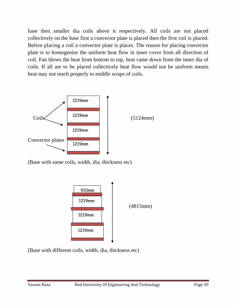
PARAMETERS FOR ANNEALING:
As coils are placed one above each other, their edges may get damaged or bend
hence increase the chance of scrap. In case if single coil is wrap out it must be
placed on the top. Generally four coils of width 1219mm each are placed one
above the other. A convector plate is placed in b/w each coil. Total height of the
furnace is 5300mm therefore total height of coils after placing must be below this.
Also 6 coils of 772mm with each or 5 coils of 910mm width each can be placed on
the base.
PARAMETERS FOR COIL PLACEMENT:
For good and proper annealing layers of coil should be wind proper so that weight
of coil must act uniformly on charge plate. It is generally in practice that all coils
placed in furnace must have same thickness, diameter, and width, no of passes etc.
If different dia coils are to be placed, the larger diameter coil must place first at the
Yaseen Raza Ned University Of Engineering And Technology Page 39
base then smaller dia coils above it respectively. All coils are not placed
collectively on the base first a convector plate is placed then the first coil is placed.
Before placing a coil a convector plate is places. The reason for placing convector
plate is to homogenize the uniform heat flow in inner cover from all direction of
coil. Fan blows the heat from bottom to top, heat came down from the inner dia of
coils. If all are to be placed collectively heat flow would not be uniform means
heat may not reach properly to middle wraps of coils.
Coils (5124mm)
Convector plates
(Base with same coils, width, dia, thickness etc)
(4815mm)
(Base with different coils, width, dia, thickness etc)
1219mm
1219mm
1219mm
910mm
1219mm
1219mm
1219mm
1219mm
Yaseen Raza Ned University Of Engineering And Technology Page 40
CONVECTOR PLATES:
Two different thickness convector plates are used
For < 0.5mm 82mm thickness convector plate is used. For > 0.5mm 62mm
thickness convector plate is used. Convertor plate is placed by arm gripper.
ANNEALING PROCESS:
It takes about an hour to charge the base with capacity of 4 coils. After placing the
inner cover we perform a test to check out leakage if any in the cover after physical
inspection of cover we hold it for 18-20min by flowing N2. This is to remove
oxygen content from inner cover when there is no alarm during safety purge we
plug the heating bell then the heating start (nozzle of CH4+H2+N2 are placed
properly).
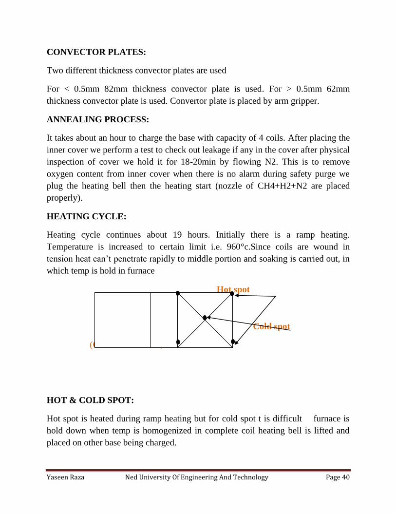
HEATING CYCLE:
Heating cycle continues about 19 hours. Initially there is a ramp heating.
Temperature is increased to certain limit i.e. 960°c.Since coils are wound in
tension heat can’t penetrate rapidly to middle portion and soaking is carried out, in
which temp is hold in furnace
Hot spot
Cold spot
(Coil cross section)
HOT & COLD SPOT:
Hot spot is heated during ramp heating but for cold spot t is difficult furnace is
hold down when temp is homogenized in complete coil heating bell is lifted and
placed on other base being charged.
Yaseen Raza Ned University Of Engineering And Technology Page 41
BURNERS:
Total 8 burners are used ignited by natural gas and oxygen from blower air is
transferred to heat exchanger than to burners first pilot burner is start to start
ignition than all burner starts. One outer burner is than ignited by used hydrogen
going out. Inner cover is filled by hydrogen gas when burning starts in heating
bell, heat energy which is generated heats up the inner cover. Heat from inner
cover is conducted by hydrogen gas & transferred to coils in this way coils are
heated to softening point direct heat is not applied b/c it may melt the sheets or
may cause change in structure.
COOLING CYCLE:
As heating is completed heating bell is allowed to slow cool to a temp of 600°C.
Then heating bell is lifted & cooling bell is placed on the base two types of coiling
mechanism is used.
Air cooling & Water cooling:
Air cooling is carried out first. Temp is reduced to 380°c. For two hours it is
continue than water coiling starts from 380°c. A temperature is set i.e. 60°C but
time duration is not set.
It is a slow cooling process if we cool the inner cover rapidly certain problems may
be caused. Outer layers will cool more than the inner layers of coil. As the temp is
reached the cooling bell is lifted & placed on other base whose heating is complete
or about to complete. Coils are discharged from the base. First inner cover is
removed by the help of arm gripper the coil is removed. Convector plate is
removed than coil is removed respectively. It takes about 1 hour to discharge base
coils are placed in stock area then transferred to tilter than to skin pass mill.
Yaseen Raza Ned University Of Engineering And Technology Page 42
SKIN PASS ROLLING:
Skin pass rolling also called Temper rolling, is a finishing operation in the
production of thin strips of steel and nonferrous metals. It consists of cold rolling
with very low reduction of area (not more than 3 percent). As a rule, the metal is
subjected to temper rolling after heat treatment. Temper rolling increases the yield
point reducing the possibility of formation of flow lines, which mark the surface of
products, on the metal during cold stamping
OBJECTIVE OF SKIN PASS:
The main objectives of the skin-pass are to modify the mechanical features of the
strip steel and provide the surface finish required by the client. This improves the
range and quality of the manufactured product whereby the required roughness, the
sheet is given well defined mechanical, technological and geometrical properties
(yield stress, roughness, and flatness) by the final cold forming process in the skin
pass mill. Temper rolling is necessary for sheet metal that is to undergo cold
forging with deep drawing, such as sheet steel intended for making motor-vehicle
body parts and sheet iron. Depending on the purpose of the sheet metal, its surface
is worked to various degrees during temper rolling, and it is partially aligned in the
process. Temper rolling is done in skin-pass mills, usually in one stroke, and less
frequently in several strokes. This involves a controlled light reduction to establish
the final thickness, impart the desired surface finish, flatten the strip to improve
shape and create the required hardness of the material.
SKIN PASS MILL:
After annealing, the steel has been so thoroughly relieved of internal stresses that it
has a tendency not to bend uniformly, resulting in localized strains during
subsequent forming operations. To counter this, a light reduction, between ½ to 3
percent of the thickness, is taken at the Skin Pass Mill/ Temper Mill. Temper Mill
is made up of a ‘4-Hi’ rolling mill stands. This arrangement gives operators the
flexibility to improve the flatness of the product and to allow a ‘matte’ surface
finish to be applied by the shot-blasted work-rolls while meeting the targeted
reduction, or ‘extension’. Work rolls are changed each day or so, after which the
scheduled coils are processed.
Yaseen Raza Ned University Of Engineering And Technology Page 43
SKIN PASS PROCESS:
Power is delivered from the mill motors to the backup rolls, which turn the work
rolls, which in turn roll the steel. The reductions are much smaller, so less tension
is held between stands and the roll coolant / emulsion is normally used. Operators
at the temper mill are relied upon to make most adjustments based on the rolling
parameters and product appearance.
Oil can be applied either ‘light’ or ‘heavy’ by coating the top surface of the coil as
it is wound onto the tension reel. If necessary to make the customer’s coil weight
requirements, coils can be split with a shear at the exit of the last stand. At the exit
side of the mill, an X-ray thickness measurement device uses to record the gauge
of the steel. Both the entry and exit ends consist of rubber-coated wheels that are
turned by the strip; each revolution is counted and translated into a length
measurement.
PREPARATION AND THREADING:
Coils are first transferred from annealing to skin pass mill. First coils are placed on
a tilter than transferred to SKM stock area. Then coil is placed on uncoiler
mandrel. Large electro-mechanical screws allow for adjustment of the gap between
work rolls. An operator monitors the threading of the sheet. After the head-end is
under wound onto the tension reel, and tension has been established through the
mills, the operator makes further adjustments to the roll gaps, tension settings, and
work-roll bending (up to 110 tons).
Initially, steel is slowly rolled while final adjustments are made; when the operator
is satisfied, the mills accelerate to their run speed - up to 300 meters per minute at
which further adjustments are not normally made. The low-volume lubrication
system applies the lubricant in the skin-pass stand entry. This reduces the friction
in the roll gap and hence the roll force, and improves flatness while using a
minimum amount of lubricant.
TAIL-OUT AND INSPECTION:
When the coil has paid off down to the last few wraps, it is sheared and the inner-
most, off-gauge wraps are removed from the mandrel with the help of coil car and
scrapped. At the exit end, the finished coil is manually banded by an operator with
a single, circumferential, strip. A short sample is sheared from the tail of the coil at
Yaseen Raza Ned University Of Engineering And Technology Page 44
the exit end and examined to assess the quality of the coil’s surface, confirm the
dimensions, and evaluate the hardness and thickness. Where indicated on the
schedule, the surface texture of the sample is evaluated to ensure the customer will
be able to paint, or otherwise process, the steel efficiently.
DISCHARGING:
The metallurgical properties of the steel are evaluated by examining the Rockwell
Hardness of the steel. It improves the range and quality of the manufactured
product whereby the required roughness, surface quality, and metallurgic product
modifications are obtained to attain excellent homogenization of the crystalline
grain and the final surface shine. Coils are packed at the packing plant to protect
the steel: high-quality paper is wrapped around the coil and protectors placed on
the corners reduce transportation damage.
ROLL GRINDING:
In grinding shop, grinding of rolls for 4hi mill and skin pass mill is carried out. The
purpose of grinding is to eliminate the roll defects like cracks, fire cracks, sheet
sticking etc.
ROLL GRINDING PARAMETERS:
Each roll has to be ground after certain duration of running. Work roll for 4 hi mill
has to be grind after running of 200Km circumferential distance. Backup roll for 4
hi mill has to be grind after running of 3000km circumferential distance. Rolls are
detached from the mill by roll changing machine, and then transferred to roll
grinding shop by crane and placed on the saddle. Initially they are in hot condition;
therefore, they are cooled for about 24 hours at room temperature.
PROCESS:
Roll is cleaned first by cleaner so that the surface may clean of emulsion, grease
etc. Grinding of work roll requires approximate one hour and for backup roll, about
twelve hours minimum requires.
Yaseen Raza Ned University Of Engineering And Technology Page 45
As the roll is placed on the steady of grinding machine, its alignment has to be
adjusted manually by gears. Initially surface of the rolls has to be observed i.e.
either it has visible cracks, sheet sticking etc or not. If surface does not have visible
cracks, a predefined program runs on grinding machine`s computer to perform
grinding. About twenty microns (200µm) is grind for this condition. Sometimes
rolls may have visible cracks or sheet stick to it. Their grinding process is a bit
different from normal grinding of roll. They are grind to about fifty microns
(500µm).
Before starting the grinding, position of roll is set according to parameters.
Emulsion flow is checked, condition of grinding wheel is inspected. Silicon
carbide grinding wheel is used for grinding. Dia of grinding wheel is 710mm.
NON DESTRUCTIVE TESTING (NDT):
In non destructive testing, the sample under test is not destroyed. A penetrant is
sprayed on the barrel of roll. It penetrates into the crack surface. Again the surface
is cleaned, a developer is sprayed and if there are cracks, they become visible.
Then with respect to the depth of the crack, roll is grind again to eliminate the
crack.
CONCLUSION:
My internship duration at ISL was superb, I had learned a lot regarding all the
processes. All personals; HODs`, managers, operators etc were very cooperative.
Furthermore I want to say that there are a few things need to be looked out. There
was not any proper planning of HR department regarding internees. We were
divided in groups for ten days of each department, but plan wasn’t followed, we
were at CRM for about a month.
ISL provides a very good environment for learning process like Cold rolling,
galvanizing etc. Hope that it will progress more in upcoming future and keep on
providing such type of learning sessions to us.