Embed Size (px)
Citation preview
Internship Report HPFL 2012
1
INTERNSHIP REPORT
SCHOOL OF CHEMICAL AND MATERIALS ENGINEERING (SCME)
NATIONAL UNIVERSITY OF SCIENCES AND TECHNOLOGY
H-12 , ISLAMABAD
Internship Report HPFL 2012
2
1 DECLARATION
_____________________________________ July 30, 2012
TO WHOM IT MAY CONCERN Dear Sir:
Submitted for your review is the report of our internship at Production Unit of
Hazara Phosphate Fertilizer Private Ltd. Haripur Hazara plant, during July 2012.
It is hereby declared that the report is compiled in long report format, as per
the guidelines and is based upon the literature review; plant manuals and
standard operating procedures; process flow diagrams and sharing and
learning from management and staff of the company.
It is anticipated that response will be reflected.
Regards ,
Muhammad Zubair
Undergraduate Student
School of Chemical and Materials Engineering (SCME)
National University of Sciences and Technology (NUST)
H-12 Campus, Islamabad – 44000
2010 – NUST – BE – CHE– 19
Email: [email protected]
Contact: 0321-6711529
Kashif Nadeem
Undergraduate Student
School of Chemical and Materials Engineering (SCME)
National University of Sciences and Technology (NUST)
H-12 Campus, Islamabad – 44000
2010 – NUST – BE – CHE– 10
Email: [email protected]
Contact: 0341-7448894
Internship Report HPFL 2012
3
2 ACKNOWLEDGEMENTS
Author is thankful to
Almighty Allah,
For His unlimited blessings and bounties,
And for keeping him sane, sound and successful;
His parents and friends,
For all their support and trust in him and his aims;
His teachers and guides,
For teaching him things he knew not;
Lec Abdur Razzaq,
For bringing the opportunity of this excellent learning and exposure;
And last but never the least
Management and Staff of Hazara Phosphate Fertilizer Private Ltd
Especially Plant Managers, Shift Engineers and Operators,
For their utmost help, guidance and time
Which made author make most of his internship at plant site;
Internship Report HPFL 2012
4
INTRODUCTION
LOCATION OF THE PLANT
PURPOSE OF THE PLANT
SINGLE SUPERPHOSPHATE PLANT
SULPHURIC ACID PLANT
WATER TREATMENT PLANT
SAFETY
ANALYSIS LAB
Internship Report HPFL 2012
5
INTRODUCTION
Hazara Phosphate Fertilizers (Private) Limited (HPFL) is a public sector company.
HPFL is located in Haripur, NWFP 75 KM from Islamabad. The factory is situated
on 57 acres of developed land, and includes factory, housing and other
amenities. HPFL was incorporated under the Companies Ordinance 1984 in June
1985 as a private limited company and commenced commercial operation in
1989.
HPFL is operating in the fertilizer industry and manufactures Granulated Single
Super Phosphate (GSSP) fertilizers using a combination of indigenous phosphate
rock from the Kakul mines in proximity of plant and imported rock from Jordan
and Morocco. Since 1999 rock phosphate is being imported mainly from Jordan
for manufacture of GSSP, because of non-availability of local rock phosphate.
HPFL has authorized share capital of Rs.200 million divided into 20 million
ordinary shares of Rs.10 each. Out of these 19,143,207 ordinary shares have
been issued, subscribed and fully paid up as on June 30, 2007.
National Fertilizers Corporation (NFC) holds 100% equity in HPFL. NFC was
incorporated as a private limited company on August 11, 1973, with an
authorized share capital of Rs.1,000 million, which was subscribed entirely by
the Government of Pakistan.
Operational management comprises of a Managing Director and General
Manager. Total personnel strength of regular staff plus daily wages labour as at
June 30, 2007 was 261.
The break down of staff is given as under;
Management / Executives 35
Non-Executive 88
Daily Wages Labour 138
Internship Report HPFL 2012
6
LOCATION OF THE PLANT
HPFL is located in Haripur, KPK 75 KM from Islamabad. The factory is situated
on 57 acres of developed land, and includes factory, housing and other
amenities.
PURPOSE OF THE PLANT
To produce single super phosphate to keep the agricultural system of our
country up right and to ensure maximum production of crops.
.
Internship Report HPFL 2012
7
SINGLE SUPERPHOSPHATE PLANT

Internship Report HPFL 2012
8
SINGLE SUPERPHOSPHATE PLANT:
Single Super Phosphate Plant consists of Three separate units namely
Run of Pile (ROP) section
Granulation plant(GP) Section
Bagging section
ROP SECTION:
ROP section consists of following parts :
Crusher
Hopper
Bucket elevator
Level hopper
Feeder
Grinding mill
Cyclones
Screw conveyor
Main bucket elevator
Main hopper
screw conveyor
Dosimeter
Acid dilution unit
Mixer
Drum den
Leather conveyor
Storage
Internship Report HPFL 2012
9
RAW MATERIAL
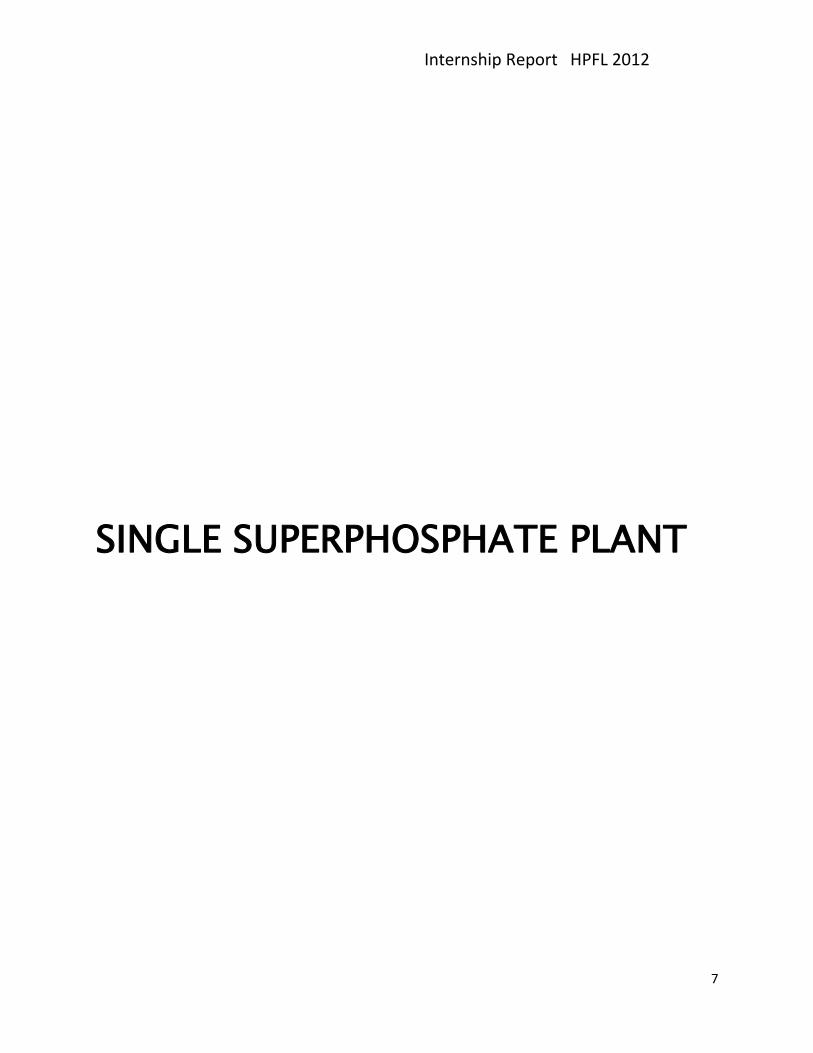
Raw material taken is containing about 10% phosphate content and is taken
from Kakul . This phosphate cannot be taken by plants and is not taken uproot
by the plants . Raw material is transported to the plant by trucks . The material
is weighed in the weighing place . Now the material is unloaded into the
crusher which crushes it to about 4-5 mm in size . This size is enough for the
feed to the mill . A storage is present on the plant to store this raw material to
ensure a good stock for the batch preparation .
The basic purpose which we have to do is to make the phosphate soluble , so
that it can be easily used in the soil . In Run Of Pile (ROP) system , basically all
physical processes are taking place and the raw material is mixed with
sulphuric aicd to make it a substance which has a phosphate which can be
readily absorbed by the crops . Fine groundeng of the material ensures that the
material gets easily mixed with the sulphuric acid .
The phosphorus content of the raw material is checked in the laboratory for
further calculations and the batch preparation . This is necessary because we
want about 16% amount of soluble phosphorus at the end .
Internship Report HPFL 2012
10
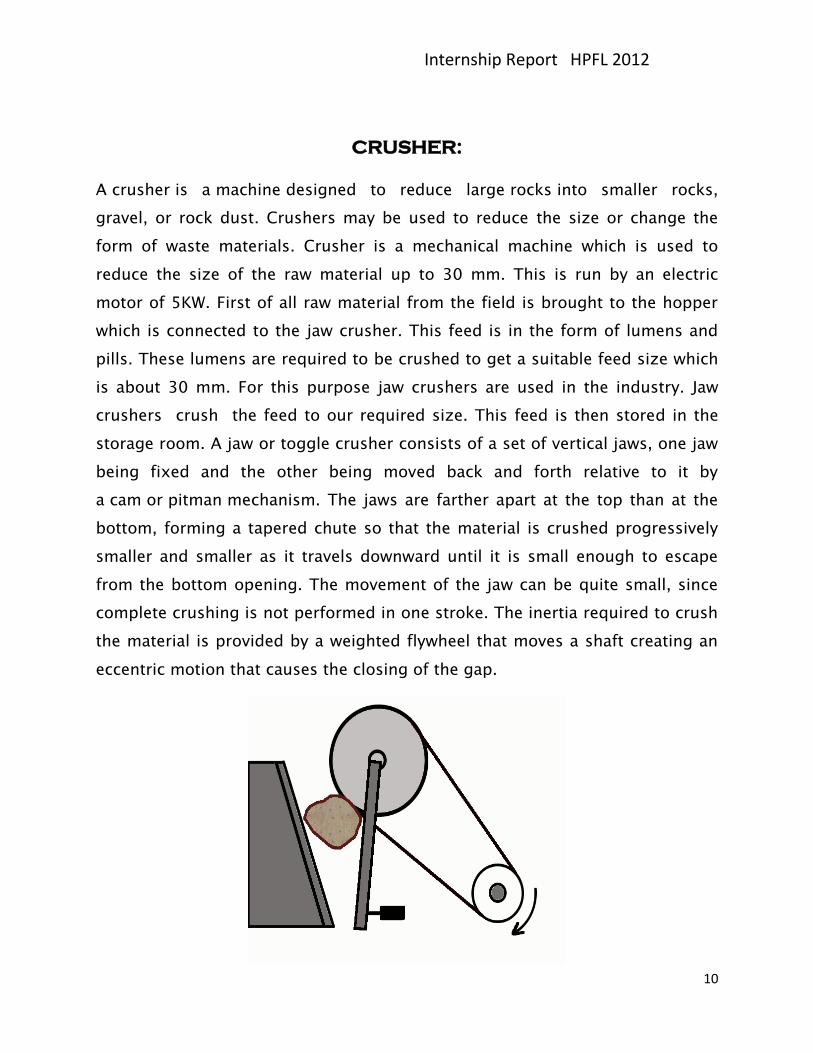
CRUSHER:
A crusher is a machine designed to reduce large rocks into smaller rocks,
gravel, or rock dust. Crushers may be used to reduce the size or change the
form of waste materials. Crusher is a mechanical machine which is used to
reduce the size of the raw material up to 30 mm. This is run by an electric
motor of 5KW. First of all raw material from the field is brought to the hopper
which is connected to the jaw crusher. This feed is in the form of lumens and
pills. These lumens are required to be crushed to get a suitable feed size which
is about 30 mm. For this purpose jaw crushers are used in the industry. Jaw
crushers crush the feed to our required size. This feed is then stored in the
storage room. A jaw or toggle crusher consists of a set of vertical jaws, one jaw
being fixed and the other being moved back and forth relative to it by
a cam or pitman mechanism. The jaws are farther apart at the top than at the
bottom, forming a tapered chute so that the material is crushed progressively
smaller and smaller as it travels downward until it is small enough to escape
from the bottom opening. The movement of the jaw can be quite small, since
complete crushing is not performed in one stroke. The inertia required to crush
the material is provided by a weighted flywheel that moves a shaft creating an
eccentric motion that causes the closing of the gap.
Internship Report HPFL 2012
11
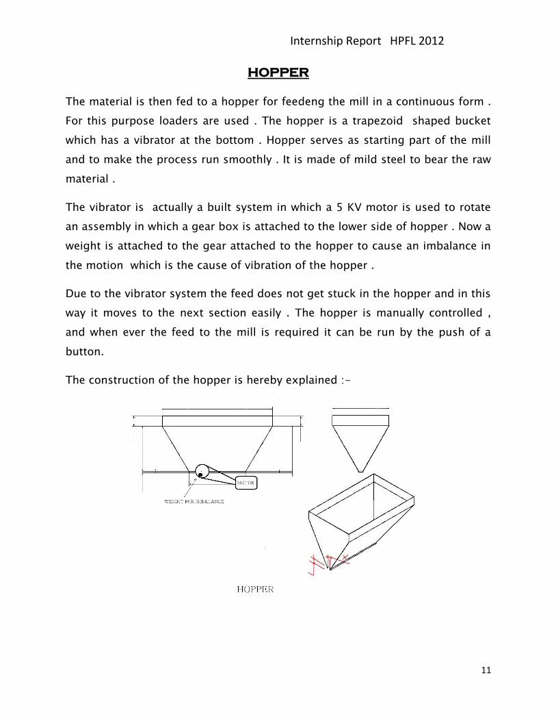
HOPPER
The material is then fed to a hopper for feedeng the mill in a continuous form .
For this purpose loaders are used . The hopper is a trapezoid shaped bucket
which has a vibrator at the bottom . Hopper serves as starting part of the mill
and to make the process run smoothly . It is made of mild steel to bear the raw
material .
The vibrator is actually a built system in which a 5 KV motor is used to rotate
an assembly in which a gear box is attached to the lower side of hopper . Now a
weight is attached to the gear attached to the hopper to cause an imbalance in
the motion which is the cause of vibration of the hopper .
Due to the vibrator system the feed does not get stuck in the hopper and in this
way it moves to the next section easily . The hopper is manually controlled ,
and when ever the feed to the mill is required it can be run by the push of a
button.
The construction of the hopper is hereby explained :-
Internship Report HPFL 2012
12
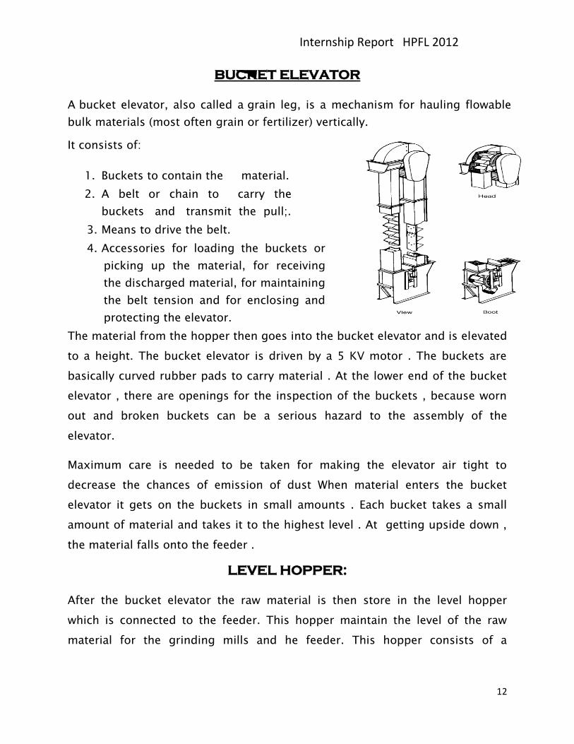
BUCKET ELEVATOR
A bucket elevator, also called a grain leg, is a mechanism for hauling flowable
bulk materials (most often grain or fertilizer) vertically.
It consists of:
1. Buckets to contain the material.
2. A belt or chain to carry the
buckets and transmit the pull;.
3. Means to drive the belt.
4. Accessories for loading the buckets or
picking up the material, for receiving
the discharged material, for maintaining
the belt tension and for enclosing and
protecting the elevator.
The material from the hopper then goes into the bucket elevator and is elevated
to a height. The bucket elevator is driven by a 5 KV motor . The buckets are
basically curved rubber pads to carry material . At the lower end of the bucket
elevator , there are openings for the inspection of the buckets , because worn
out and broken buckets can be a serious hazard to the assembly of the
elevator.
Maximum care is needed to be taken for making the elevator air tight to
decrease the chances of emission of dust When material enters the bucket
elevator it gets on the buckets in small amounts . Each bucket takes a small
amount of material and takes it to the highest level . At getting upside down ,
the material falls onto the feeder .
LEVEL HOPPER:
After the bucket elevator the raw material is then store in the level hopper
which is connected to the feeder. This hopper maintain the level of the raw
material for the grinding mills and he feeder. This hopper consists of a
Internship Report HPFL 2012
13
vibrating motor which is joined to the external wall of the hopper so that if the
feed is wet then it cannot stick to the walls of the hopper to the internal side.
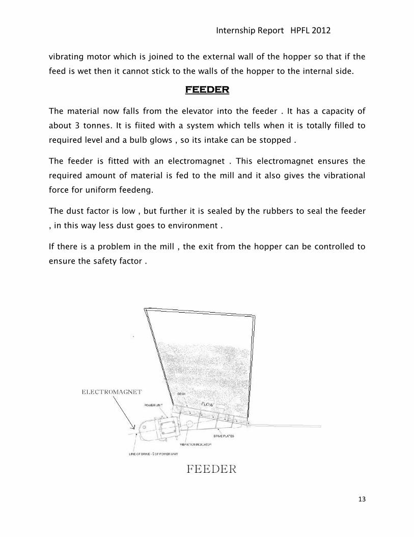
FEEDER
The material now falls from the elevator into the feeder . It has a capacity of
about 3 tonnes. It is fiited with a system which tells when it is totally filled to
required level and a bulb glows , so its intake can be stopped .
The feeder is fitted with an electromagnet . This electromagnet ensures the
required amount of material is fed to the mill and it also gives the vibrational
force for uniform feedeng.
The dust factor is low , but further it is sealed by the rubbers to seal the feeder
, in this way less dust goes to environment .
If there is a problem in the mill , the exit from the hopper can be controlled to
ensure the safety factor .
Internship Report HPFL 2012
14
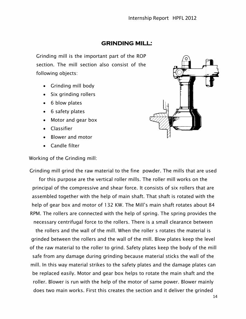
GRINDING MILL:
Grinding mill is the important part of the ROP
section. The mill section also consist of the
following objects:
Grinding mill body
Six grinding rollers
6 blow plates
6 safety plates
Motor and gear box
Classifier
Blower and motor
Candle filter
Working of the Grinding mill:
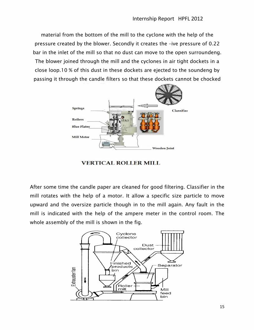
Grinding mill grind the raw material to the fine powder. The mills that are used
for this purpose are the vertical roller mills. The roller mill works on the
principal of the compressive and shear force. It consists of six rollers that are
assembled together with the help of main shaft. That shaft is rotated with the
help of gear box and motor of 132 KW. The Mill’s main shaft rotates about 84
RPM. The rollers are connected with the help of spring. The spring provides the
necessary centrifugal force to the rollers. There is a small clearance between
the rollers and the wall of the mill. When the roller s rotates the material is
grinded between the rollers and the wall of the mill. Blow plates keep the level
of the raw material to the roller to grind. Safety plates keep the body of the mill
safe from any damage during grinding because material sticks the wall of the
mill. In this way material strikes to the safety plates and the damage plates can
be replaced easily. Motor and gear box helps to rotate the main shaft and the
roller. Blower is run with the help of the motor of same power. Blower mainly
does two main works. First this creates the section and it deliver the grinded
Internship Report HPFL 2012
15
material from the bottom of the mill to the cyclone with the help of the
pressure created by the blower. Secondly it creates the –ive pressure of 0.22
bar in the inlet of the mill so that no dust can move to the open surroundeng.
The blower joined through the mill and the cyclones in air tight dockets in a
close loop.10 % of this dust in these dockets are ejected to the soundeng by
passing it through the candle filters so that these dockets cannot be chocked
After some time the candle paper are cleaned for good filtering. Classifier in the
mill rotates with the help of a motor. It allow a specific size particle to move
upward and the oversize particle though in to the mill again. Any fault in the
mill is indicated with the help of the ampere meter in the control room. The
whole assembly of the mill is shown in the fig.
Internship Report HPFL 2012
16
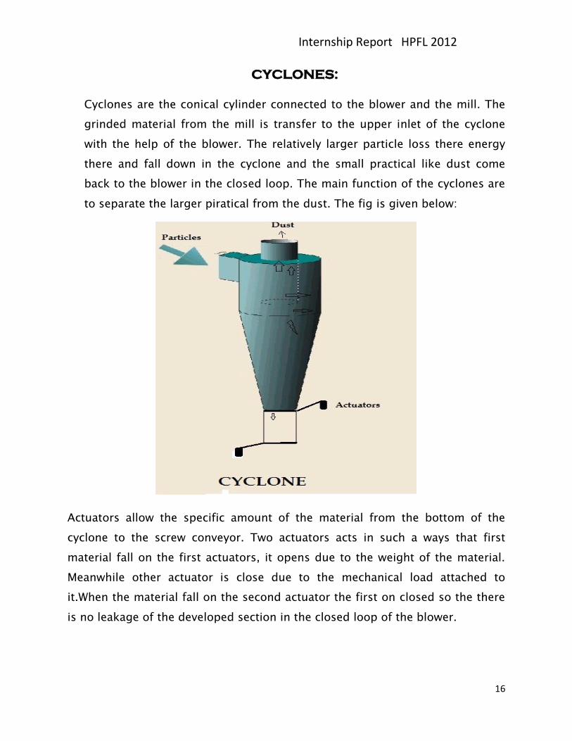
CYCLONES:
Cyclones are the conical cylinder connected to the blower and the mill. The
grinded material from the mill is transfer to the upper inlet of the cyclone
with the help of the blower. The relatively larger particle loss there energy
there and fall down in the cyclone and the small practical like dust come
back to the blower in the closed loop. The main function of the cyclones are
to separate the larger piratical from the dust. The fig is given below:
Actuators allow the specific amount of the material from the bottom of the
cyclone to the screw conveyor. Two actuators acts in such a ways that first
material fall on the first actuators, it opens due to the weight of the material.
Meanwhile other actuator is close due to the mechanical load attached to
it.When the material fall on the second actuator the first on closed so the there
is no leakage of the developed section in the closed loop of the blower.
Internship Report HPFL 2012
17
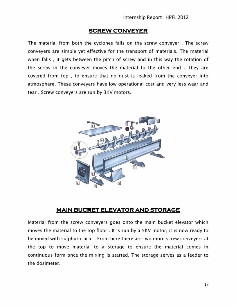
SCREW CONVEYER
The material from both the cyclones falls on the screw conveyer . The screw
conveyers are simple yet effective for the transport of materials. The material
when falls , it gets between the pitch of screw and in this way the rotation of
the screw in the conveyer moves the material to the other end . They are
covered from top , to ensure that no dust is leaked from the conveyer into
atmosphere. These conveyers have low operational cost and very less wear and
tear . Screw conveyers are run by 3KV motors.
MAIN BUCKET ELEVATOR AND STORAGE
Material from the screw conveyers goes onto the main bucket elevator which
moves the material to the top floor . It is run by a 5KV motor, it is now ready to
be mixed with sulphuric acid . From here there are two more screw conveyers at
the top to move material to a storage to ensure the material comes in
continuous form once the mixing is started. The storage serves as a feeder to
the dosimeter.
Internship Report HPFL 2012
18
DOSIMETER:
Dosimeter is a mechanical device which measure the amount of the material
which is convey to the mixer. It is simply a conveyor run by an electric motor of
5 KW. It operating flow rate is about 10054 Kg/h. It takes the material from the
main hopper and drop this this material to the mixer.
ACID DILUTION UNIT
Acid use in the formation of SSP requires is about 68 to 70%. We have 98.5%
acid store in the storage tank. So we have to dilute this acid for the best result.
This is done in the Acid dilution unit. The process of dilution of sulphuric acid
is an exothermic process . This evolves a reasonable amount of heat which is to
be removed before the mixing of this acid .
For this purpose a block heat exchanger is used. Acid solution is moved from
the pipe in many passes and the water in the surrounding of these pipes is
passed to cool the acid solution. Countercurrent flow ensures maximum heat
transfer .The total surface area of the Block is 11.8 m2. In this way we get our
require degree of dilution of the acid.
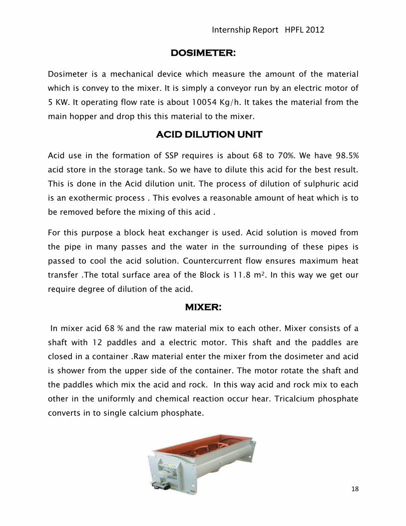
MIXER:
In mixer acid 68 % and the raw material mix to each other. Mixer consists of a
shaft with 12 paddles and a electric motor. This shaft and the paddles are
closed in a container .Raw material enter the mixer from the dosimeter and acid
is shower from the upper side of the container. The motor rotate the shaft and
the paddles which mix the acid and rock. In this way acid and rock mix to each
other in the uniformly and chemical reaction occur hear. Tricalcium phosphate
converts in to single calcium phosphate.
Internship Report HPFL 2012
19
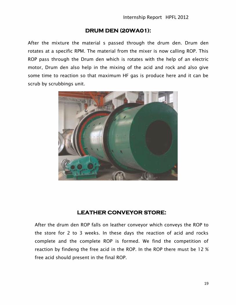
DRUM DEN (20WA01):
After the mixture the material s passed through the drum den. Drum den
rotates at a specific RPM. The material from the mixer is now calling ROP. This
ROP pass through the Drum den which is rotates with the help of an electric
motor, Drum den also help in the mixing of the acid and rock and also give
some time to reaction so that maximum HF gas is produce here and it can be
scrub by scrubbings unit.
LEATHER CONVEYOR STORE:
After the drum den ROP falls on leather conveyor which conveys the ROP to
the store for 2 to 3 weeks. In these days the reaction of acid and rocks
complete and the complete ROP is formed. We find the competition of
reaction by findeng the free acid in the ROP. In the ROP there must be 12 %
free acid should present in the final ROP.
Internship Report HPFL 2012
20
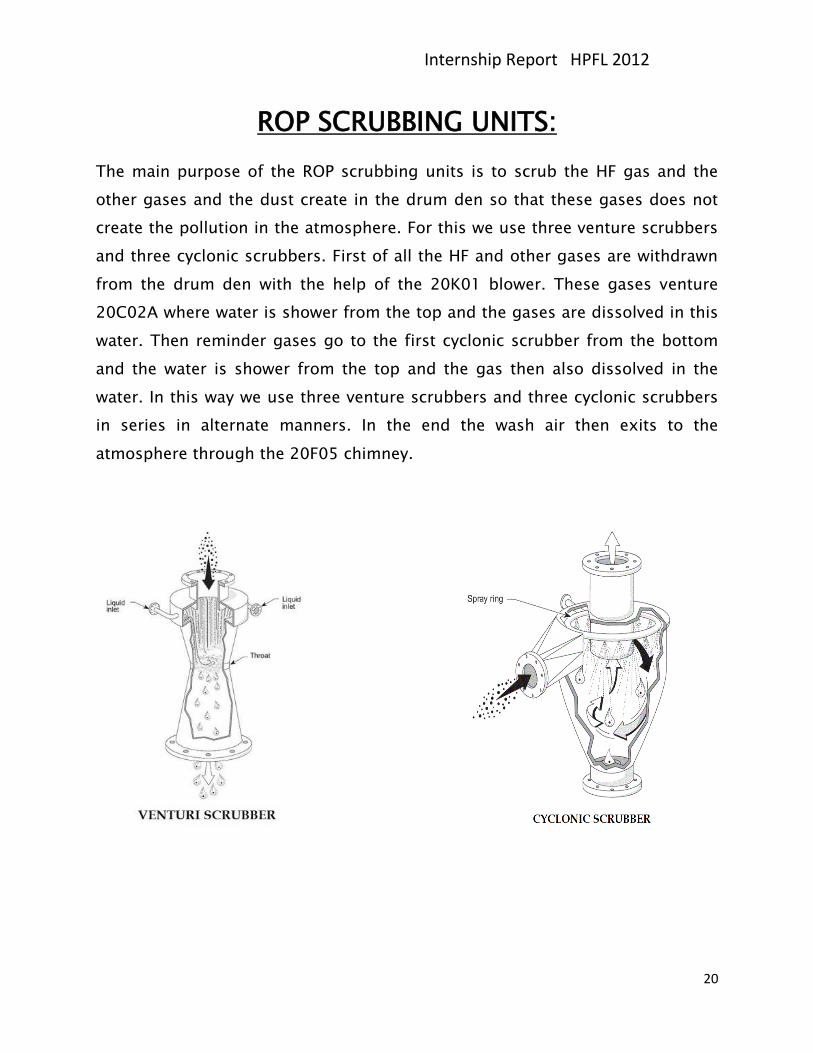
ROP SCRUBBING UNITS:
The main purpose of the ROP scrubbing units is to scrub the HF gas and the
other gases and the dust create in the drum den so that these gases does not
create the pollution in the atmosphere. For this we use three venture scrubbers
and three cyclonic scrubbers. First of all the HF and other gases are withdrawn
from the drum den with the help of the 20K01 blower. These gases venture
20C02A where water is shower from the top and the gases are dissolved in this
water. Then reminder gases go to the first cyclonic scrubber from the bottom
and the water is shower from the top and the gas then also dissolved in the
water. In this way we use three venture scrubbers and three cyclonic scrubbers
in series in alternate manners. In the end the wash air then exits to the
atmosphere through the 20F05 chimney.
Internship Report HPFL 2012
21
PROCESS OF ROP SECTION:
First of all the raw material in the form of large stone is grinded with the help of
the jaw crusher and store the material in the store. The sample of the raw
material is taken and tested in the Chemical Lab and find the amount of the P in
the raw material. If the %age of the P is below then 14% then we add TSP or DAP
to maintain the amount of the P to14% in the feed. Then this feed is convey to
the hopper by the loaded. Feed from the hopper reach the grinding mill
through the bucket elevator ,level hopper and feeder. Grinding mill is the
vertical roller mill which consists of 6 rollers. This mill grinds the feed to the
fine powder. This grinded material goes to the cyclone through the classifier
and the different dockets with the help of the Blower. The size of the grinded
material is up to -270 to -280 mesh. This material goes to the main hopper
with the help of main bucket elevator and screw conveyor. Then material moves
tower the mixer through the dosimeter and acid id added to the feed and
reaction is occur in the mixer and drum den. After drum den the ROP moves
tower the ROP storage through conveyor 11,12, and 13.the HF gas and other
dust moves tower the scrubbing section with the help of blower.
GENERAL STARTUP PROCEDURE:
Before starting the ROP section ,it is necessary to visit all the section and
conveyor of the plant. Confirm it that all the parts are ready.Then start the
section as
1. Start belt conveyor 13
2. Start belt conveyor 12
3. Start belt conveyor 11
4. Start the drum den
5. Start the mixer And supply of the acid
Internship Report HPFL 2012
22
6. Start 20N01
7. Top screw conveyor
8. Main bucket elevator
9. Screw conveyor
10. Classifier
11. Blower
12. Grinding mill
13. Hopper motor
GENERAL SHUTDOWN PROCEDURE:
Stop the section in the following manners:
1. Hopper
2. Blower
3. Classifier
4. Screw conveyor
5. Bucket elevator
6. Top screw conveyor
7. 20N01
8. Mixer
9. Drum den
10. Belt conveyor 11
11. Belt conveyor 12
12. Belt conveyor 13
Internship Report HPFL 2012
23
GRANULATIONS PLANT(GP) SECTION
GP section consists of the following parts:
ROP hopper
Jaw crusher
Belt conveyor
ROP main hopper
Main belt conveyor
Granulator
Furnace and dryer
Double docket screen
Hammer crusher
Product belt conveyor
product storage
ROP HOPPER:
The Rop after the 2 to 3 weeks placed in the ROP hopper with the
help of the loader in the ROP storage room. This hopper vibrates with the help
of the electric moter with unbalance centrifugal force and the spring.
JAW CRUSHER:
The ROP from the hopper comes to the jaw crusher. This crusher crush the ROP
to a specific size.This crusher runs with the help of the Electric motor. Actually
the ROP converted in to large lumens and they are required to crush them for
the granulator.
Internship Report HPFL 2012
24
BELT CONVEYOR AND ROP MAIN HOPPER:
After the crusher the ROP goes in to the main ROP hopper through Belts
conveyorsand finally fall in to the main hopper. The level of the hopper is auto
control . When the level of the ROP increases in the main hopper the system
closed the belts conveyor and the more supply of the ROP stops .After the level
decrease the conveyors run automatically.
MAIN BELT CONVEYOR (20 WE 15):
The ROP from the main hopper falls on the main belt conveyor. This conveyor is
very important because all the Dust practical, oversize, undersize and other
ROP falls on this conveyor. This conveyor feed the Granulator.
GRANULATOR:
Granulator is the very important part of the GP section. It is a cylindrical
shaped drum rotated with the help of the electric motor. It works in such a
way that the ROP from the main conveyor falls in the Granulator and a small
amount of the water is also added in the ROP in it. The amount of the water is
control manually. The amount of the water helps to the ROP to gain granular
shape. The shape of the ROP is form by the restoring force of the rubber wall
of the Granulator.
FURNACE AND DRYER
Furnace and dryer consist of the following parts:
Air blowers (20 K 07 and 20 K o8)
Furnace body
Dryer
Dryer motor and gear box
Internship Report HPFL 2012
25
First of all start the furnace and the two blowers. First blower builds the flame
of the fire in the furnace and other gives the air to produce the hot air for the
drying .The inlet temperature of the furnace is about 1000C and the
temperature on the outlet of the furnace is about 3000C.This high temperature
create the hot air.
The wet ROP from granulator then goes in the dryer. The hit air comes in
the dryer from the furnace. The dryer rotate at a specific rate with the help of
motor and gear box. Hot air dry the wet ROP. The moisture at the end of the
dryer should be about 5-6%. Then the hot SSP is put in the bucket elevator to
the top floor.
DOUBLE DOCKET SCREEN:
After the main bucket elevator the place a Double docket screens to separate
the oversize and undersize product and our actual product. The double docket
screen has two meshes on one another. The first on has a hole of 6 mm2.It
allow the product of size less than 6mm2 to pass it. Larger size particles not
pass through it and they are called over size product. This oversize product
goes tower the hammer. The second mesh has a hole of 1mm2. It allows the
material of this size to pass it. This material is called under size and this goes
tower the main belt conveyor for recycling. The product size between 6 and
1mm2 is our actual product. This product goes tower the product storage
through the belt conveyor.
HAMMER CRUSHER:
The oversize product comes in the hammer crusher. Hammer crusher crush the
material and past this material the main conveyor for recycling. Hammer
crusher consists of a roller and 36 hammers. The roller and hammers are
rotated in the opposite side. The material falls on the drum and the hammer
strikes the material with great impact .Due to this force the material breaks
down into small pieces. The crusher is run by the motor.
Internship Report HPFL 2012
26
PROCESS OF GP SECTION:
First of all the ROP in the storage is loaded in the hopper with the help of
loader. The material form hopper moves to the jaw crusher. Crusher crush the
material to a specific size and then material is moves tower the main ROP
hopper with the help of belt conveyor. From hopper the material goes to the
granulator where it changes in the form of grains. These granulated material
moves tower the dryer. In dryer the wet material dry with the help of hot air
coming from the furnace. The dry material from the dryer goes to the Mesh
through the bucket elevator. Double mesh classifies the mater in to under size,
oversize and product. Oversize goes tower the hammer crusher. Where the size
of the material reduce with the help of hammer. Then this material goes to the
main belt conveyor for recycling. The under size material goes to the main belt
conveyor for recycle. The product goes tower the storage room through the
product conveyor.
GP SCRUBBING UNITS:
In GP section it is necessary to wash the dust and other gases to keep the
surrounding clean. So like ROP section we also scrub all the dust of GP section
also. In GP section There are three scrubber section.
1. The dust created in the granulator 20 WA 02 is drawn from it by the
section created by the blower 20K04.This dust is first pass through the
venture 20C05 where water is shower from the above side. Dust is
dissolved in the water and the mixture of dust and water goes to the tank
20T02.After that the remaining air is passes through the tower 20G06
where water is also shower through the top of the tower. The most of the
Gases dissolved in the water and pure air is exited to the atmosphere.
2. The dust and gases created in the dryer is also passes through the
cyclones 20 JC 01 A,B with the help of the section created by the blower
Internship Report HPFL 2012
27
20K02.this dust and gases goes in to the venture 20C04,where water is
shower from the top of the venture. Dust and gases are dissolved in the
water. Then these remaining gases go to the tower 20G06.where these
gases more washed by the shower of the water. Pure air is exited to the
atmosphere. Over size material in the bottom of the cyclones goes to the
main belt conveyor for the recycling.
3. The dust created by the different belt conveyors, by hammer crusher, by
the Mesh is collected by the section created by the blower 20K04. This
dust is first passed through the cyclone 20JC02.The oversize practical in
the cyclone go tower the main conveyor for recycling. The dust then
moves tower the tower 20G06.where water is shower from the top of the
tower and dust id dissolved in the water and pure air is exited in the
atmosphere.
The water from the tank 20T02 and from tower 20G06 then goes to the water
treatment plant.
GENERAL STARTUP PROCEDURE OF GP SECTION:
First of all visit the GP section and check all the units and ensure it that all are
ready for the process. Then start the every unit according the given manner:
1. Start the product belt conveyor
2. double docket screen
3. Hammer crusher
4. Bucket elevators
5. Dryer
6. Furnace
7. Granulator
8. Main belt conveyor
9. ROP belt conveyor
10. Jaw crusher
Internship Report HPFL 2012
28
11. Hopper
GENERAL SHUTDOWN PROCEDURE FOR GP
SECTION
Stop all the units according to the following manners:
1. Hopper
2. Jaw crusher
3. ROP belt conveyor
4. Main belt conveyor
5. Granulator
6. Furnace
7. Dryer
8. Bucket elevators
9. double docket screen
10. Hammer crusher
11. Product belt conveyor
Internship Report HPFL 2012
29
BAGGING SECTION
This section consists of
product hopper
product conveyors
product storage hopper
mechanical balance
sewing machine
Bagging section consists of a hopper and belt conveyors and a balance. The
product is loaded in the hopper with the help of loader. This product goes to
the storage hopper. The mechanical balance took the product from the hopper
and weighs it and drop 50 Kg of the product to the polymer bag. The
mechanical balance has two portions. When on portion drop the product in the
bag the other portion get material from the storage hopper. These two portions
works in the alternative manner. The polymer bag after getting material are
sealed and loaded to the trucks with the help of conveyor and men labor.
Internship Report HPFL 2012
30
SULPHURIC ACID PLANT (SAP)
Internship Report HPFL 2012
31
SULPHURIC ACID PLANT (SAP):
INTRODUCTION:
Sulfuric acid (alternative spelling sulphuric acid) is a
highly corrosive strong mineral acid with the molecular formula H2SO4. It is a
colorless to slightly yellow viscous liquid which is soluble in water at all
concentrations.
Sometimes, it may be dark brown as dyed during industrial production process
in order to alert people's awareness to its hazards. The historical name of this
acid is oil of vitriol.
It is a diprotic acid which may show different properties depending upon its
concentration. Its corrosiveness on metals, stones, skin, eyes and flesh or other
materials can be mainly ascribed to its strong acidic nature and, if
concentrated, strong dehydrating and oxidizing properties.
Concentrated sulfuric acid can cause very serious damage upon contact as not
only does it hydrolyze proteins and lipids leading to chemical burn, but also
dehydrates carbohydrates resulting in secondary thermal burn. If it
contacts eyes, permanent blindness may occur So, safety precautions should
always be taken when using it. Moreover, it is hygroscopic, readily
absorbing water vapor from the air.
Possessing different chemical properties, the sulfuric acid has a wide range of
applications including domestic acidic drain cleaner electrolyte in lead-acid
batteries and various cleaning agents.
It is also a central substance in the chemical industry. Principal uses
include mineral processing, fertilizer manufacturing, refining, wastewater,
and chemical synthesis. It is widely produced with different methods, such
as contact process, wet sulfuric acid process and some other methods.
Internship Report HPFL 2012
32
GRADES OF SULFURIC ACID
Although nearly 99% sulfuric acid can be made, this loses SO3 at the boiling
point to produce 98.3% acid. The 98% grade is more stable in storage, and is
the usual form of what is described as "concentrated sulfuric acid." Other
concentrations are used for different purposes.
"Chamber acid" and "tower acid" were the two concentrations of sulfuric acid
produced by the lead chamber process, chamber acid being the acid produced
in lead chamber itself (<70% to avoid contamination with nitrosylsulfuric acid)
and tower acid being the acid recovered from the bottom of the Glover
tower They are now obsolete as commercial concentrations of sulfuric acid,
although they may be prepared in the laboratory from concentrated sulfuric
acid if needed. In particular, "10M" sulfuric acid (the modern equivalent of
chamber acid, used in many titrations) is prepared by slowly adding 98%
sulfuric acid to an equal volume of water, with good stirring: the temperature of
the mixture can rise to 80 °C (176 °F) or higher.
Massfraction
H2SO4
Density
(kg/L)
Concentration
(mol/L) Common name
10% 1.07 ~1 dilute sulfuric acid
29–32% 1.25–1.28 4.2–5 Battery acid(lead–acid batteries)
62–70% 1.52–1.60 9.6–11.5 Chamberacid fertilizer acid
78–80% 1.70–1.73 13.5–14 tower acid Glover acid
98% 1.83 ~18 concentrated sulfuric acid
Internship Report HPFL 2012
33
Sulfuric acid reacts with its anhydride, SO3, to form H2S2O7, called pyro sulfuric
acid, fuming sulfuric acid, Disulfuric acid or oleum or, less
commonly, Nordhausen acid. Concentrations of oleum are either expressed in
terms of % SO3 (called % oleum) or as % H2SO4 (the amount made if H2O were
added); common concentrations are 40% oleum (109% H2SO4) and 65% oleum
(114.6% H2SO4). Pure H2S2O7 is a solid with melting point 36 °C.
Pure sulfuric acid is a viscous clear liquid, like oil, and this explains the old
name of the acid ('oil of vitriol').
Commercial sulfuric acid is sold in several different purity grades. Technical
grade H2SO4 is impure and often colored, but is suitable for making fertilizer.
Pure grades such as United States Pharmacopeia (USP) grade are used for
making pharmaceuticals and dyestuffs. Analytical grades are also available.
Sulphuric acid is the basic and very important raw material use in the
formation of SSP in the ROP section. Sulphuric acid is transport from the acid
storage to the SSP plan through the stainless steel pipes. The temperature and
the concentration of the acid kept on a specific to avoid the corrosion in the
pipes.
Internship Report HPFL 2012
34
BASICS UNITS OF THE SULPHURIC ACID PLANT:
Hopper and belt conveyor
Melting pit
Filtring pit
Storage pit
Sulphur feed pumps
Sulphur gun
Drying chamber
Sulphur burning chamber
Waste heat exchanger
Four bed contact chamber
Steam storage
Waste heat boiler
Cold gas heat exchanger
Hot gas heat exchanger
Economizers
Inter absorption tower
Final absorption tower
Acid circulation tank
Pipe collars
Storage tanks
HOPPER AND BELT CONVEYOR:
Raw material from the storage is then feed to the hopper. Hopper is a
trapezium shaped pot which has larger cross-sectional area on upper side and
the area decrease as we move from the top to bottom of the hopper. This
hopper feed the melting pit by the belt conveyor.Best conveyor is a best mover
on the rollers with the help of motor. When the level of the sulphur reach to its
maximum level ,the conveyor stop. When the level of the sulphur is down to the
specific level ,it start again and transfer sulphur in to the melting pit.
Internship Report HPFL 2012
35
MELTING PIT:
Milting pit is a small room where the sulphur is melted with the help of the
steam. Steam is provided from the stem storage tank. The pit consist four helix
of steam pipes in four corners. Steam of 7 bar moves through these pipes. The
sulphur in the pit is melted by gaining the heat from this steam. In working
condition the inlet valve open fully but the outlet valve is open partially. In this
way steam gets more time to transfer heat and melt more sulphur. The melting
temperature of the sulphur in the melting pits keeps 1250C.Above this
temperature the sulphur change in to plastic sulphur and its viscosity increases.
The sulphur in the pit is moves with the mechanical stirrer. In this way Heat
from the steam pipes also reach in the center of the pit and molten sulphur
does not stick on the wall of the steam pipes.
FILTERING PIT:
Filtering pit is like the melting pit in shape. It also consists of for steam pipes
and a mechanical stirrer. The overflow molten sulphur in the melting pit then
moves to the filtering pit. In filtering pit molten sulphur is then filter by the
filtration chamber. All the steam pipes are coated with glass wool to minimize
the heat losses. Filtration chamber is a simply a hopper type cylinder having a
steam coated body. It consists of three leaf filter in series. The molten sulphur
from the filtering pit can pumped through these filter. Molten sulphur pass
through these filter and mud is separate from the sulphur. This mud falls down
through the filtration chamber. The steam coating prevents the sulphur to
solidify in the filtering chamber. After some time the leaf filter are cleaned to
get proper filtration. The temperature of the filtering pit is about to1280C.
STORAGE PIT:
After the melting pit the molten sulphur moves tower the storage pit. Storage
pit also contain the steam pipes to avoid the solidification of sulphur again .The
pressure in the steam lines is about 4 bar and the temperature of the molten
sulphur is 125 to 1300C in the storage pit. Storage pit contain the pure sulphur.
Internship Report HPFL 2012
36
SULPHUR FEED PUMPS:
The storage pit contains three pumps. There are two gear pump and one
centrifugal pump.This pump supply the molten sulphur to the sulphur gun with
high pressure. Some time ago there are two centrifugal pumps and one gear
pump. In the normal operation only one pump is in working condition and the
other two are on standby condition. These pumps are controlled by the control
room.
SULPHUR GUN:
Sulphur gen is made of iron. It is also coated with the steam pipes so that no
steam shuld solidify in the gun. The tip of the gen is about 5 mm in
circumference. Some time ago this tip is about 4mm.Due to the larger
production the tip size of the gum has increased. This gun received the molten
sulphur from the pumps of the storage pit with high pressure. This gun spread
the molten sulphur in the sulphur burning chamber.
DRYING CHAMBER:
Drying chamber is cylindrical tower which contain packing in it.First of all at the
bottom of the tower there is a layer of rashing ring of the diameter of 6 in. After
there is a layer of ceramic saddles of the thickness 1.8 meter. These ceramics
saddles are placed randomly. After this packing there is again a layer of rashing
rings on the top of the tower.
A Blower of the type of the double stage centrifugal type compressor is run by
the motor to give the air for sulphur burning in the sulphur burning chamber.
The pressure created by this compressor is 0.44 mbar. The rotation of the
blower is about 3000 RPM.This collect the air from the atmosphere. This air
contains 21 % oxygen and 79 % nitrogen. This air also contains the moisture in
it. It is necessary to remove this moisture. For his purpose we use drying tower.
This air is introduced in the tower from the bottom and the sulphuric acid is
shower from the top of the tower. Sulphuric acid absorbed the moisture from
Internship Report HPFL 2012
37
the air and dry air goes to the sulphur burning chamber. The packing increase
the surface and contact of the acid and air. At the top of the tower there is mist
eliminator. Mist eliminator removes the mist of air and acid. After the process
the air remove from the top of the column and the acid remove from the
bottom of the column. Ceil pot contain the sulphuric acid. It remove the acid
from the mist eliminator but does not allow to mover air from the ceil pot.
The internal wall of the cylinder is coated with rubber chlorinated paint and
then there is a lining of the stainless steel bricks. This patron saves the tower
from any acid attack and corrosion.
SULPHUR BURNING CHAMBER:
The molten sulphur from the sulphur gun is introduced in to the chamber and
dry air is introduced from the drying tower. The molten sulphur burn in the
presence of oxygen. The molten sulphur reacts with oxygen to for the sulphur
dioxide gas. The %age of SO2 and the oxygen must be in such a way that if
there is 10% SO2 then the oxygen will be 11%.The sum of these two %ages
should be equal to 21 % for the good process. The temperature of the sulphur
burning chamber is about to 1080 0C.
WASTE HEAT EXCHANGER:
Waste heat exchanger is a fire tube boiler. It consists of 169 tubes and a shell.
The hot gases from the sulphur burning chamber are then passes through the
tubes of the exchanger. The temperature of the gases is about to 1080oC.In the
shell of the exchanger we pass water and in the tubes we pass hot gases. Heat
transfer occurs from hot gases to the cooled water in the shell and steam is
produced. The inlet temperature of the hot gases is 10800C and at the outlet
temperature is 3800C.In this way we produce the steam for our process and we
get the required temperature of the SO2 gas for the convertor.
Internship Report HPFL 2012
38
STEAM STORAGE:
Steam storage is a horizontal chamber. The steam produce in the waste
heat exchanger is then store in this storage. It can bear a maximum
pressure of 15 bar. Extra steam is exit to the atmosphere if the pressure in
the storage increases through the safety valve.
FOUR BED CONTACT CHAMBER:
Four bed contact chamber has four chambers. First chamber consists of
the grating and a layer of the aluminum rings. The catalyst V2O5 in the
form of rings is placed in this section. Catalyst is coated with silica to
prevent from breaking and other actions. The tag of the catalyst is 110 and
it contains 10 V. The gases from the heat exchanger inter in the first
chamber and SO2 react with oxygen to produce SO3 gas. Maximum
conversion of SO2 is occurring in this chamber. The temperature of the
entering gases to the chamber is 4150C and the leaving from the first
chamber is 6100C.Because the energy release in this reaction and
temperature of the leaving gases increase. These gases then leave from the
chamber first. After passing the through the waste heat exchanger this
gases inter the 2nd bed at temperature 4400C .again second best has the
same construction as the first one. Remaining SO2 gas reacts with the
oxygen gas and form SO3 gas. After that these gases also leave at
temperature 5320C.This bed contain 111 catalysts which contain 11 V.In
the same manner 3rd and 4th bed acts and achieve the maximum
conversion. The inlet temperature of the 3rd bed is about 4500C and the
outlet temperature is about 4800C. The inlet temperature of the 4th bed is
about 4000C and the outlet temperature is about 4120C.
Internship Report HPFL 2012
39
WASTE HEAT EXCHANGER:
Waste heat exchanger is a shell and tubes heat exchanger. The gases that
release from the 1st bed required cooling them by this exchanger, the
gases passes through the tubes and water passes through the shell of the
exchanger. In this way heat is transfer from the hot gases tower the cool
water. Steam is produce and this heat is transfer in to the steam storage.
There are 139 tubes in this shell. The temperature difference between the
hot inlet and hot outlet is about 2300C.
COOL GAS HEAT EXCHANGER AND HOT GAS
EXCHANGER:
These exchangers are also tube and shell heat exchangers. They cool the
gases coming from the 2nd and 3rd bed respectively. In the tube side we
take the mixture of gases but in the shell side we take SO2 gas from the
inter absorption tower in the shell side. This gas has very low temperature
we have to increase the temperature of this gas. In this way we transfer
heat from the hot gases tower this cool gas. This gas then goes to the 4th
bed.
ECONOMIZERS:
Economizers are also a type of shell and tube heat exchanger. There are
two Economizers in the plant. These Economizers perform two works. First
the reducer the temperature of the exit gas from the 3rd and 4th bed to
achieve the better absorption. Secondly the heat up the boiler water feed.
Water is moving in the tubes and the gases are in the shell of the
exchanger. Due to the heat transfer we get the required temperature.
Internship Report HPFL 2012
40
ABSORPTION TOWER
There are two Absorption tower namely inter Absorption tower And final
Absorption tower. Inter absorption tower absorbe the gases coming from the
first economizer. Final absorption tower absorve the gases from the 2nd
economizer.
Absorption towers is cylindrical tower which contain packing in it.First of all at
the bottom of the tower there is a layer of rashing ring of the diameter of 6 in.
After there is a layer of ceramic saddles of the thickness 1.3 meter. These
ceramics saddles are placed randomly. After this packing there is again a layer
of rashing rings on the top of the tower.
In the inter absorption tower gases is introduce from the bottom to the tower
and aid is shower from the top. Acid absorbed the gas and form the olium.
Absorbable SO2 gas go to the 4th bed and in the final tower the gas come from
the 4th bed to the final absorption tower. In final absorption tower final
absorption occurd. The remaining gases and air then exit to the atmosphere.
ACID CIRCULATION TANK:
The oleum formed in the inter absorption tower and final absorption tower is
goes in the acid circulation tank. Water is added in this tank to the oleum and
the required concentration of acid is achieved. The concentration of acid in the
Tank is about to 98.5 %.this tank contain a centrifugal pump which pumps the
acid to the pipe cooler, drying tower, and absorption tower. The level of the
acid in the tank is 60% to the total capacity of the tank.
PIPE COOLER:
When the dissolution of the acid occur in the acid circulating tank, a lot of heat
is produced which heat the acid in this tank. We have to require a temperature
of 770C of the acid for the drying tower and the absorption towers. At this
temperature we get the maximum absorption. To cool this acid we use pipe
cooler. Hot acid From the Acid circulation tank is move through these pipes
Internship Report HPFL 2012
41
and cool water is shower on these pipes. Water absorbed the heat and we get
the acid at required temperature. The overflow acid from the Acid circulation
tank is also cool to the to the 470C temperature by these pipes and this acid
moves tower the acid storage tank.
ACID STORAGE TANK:
In HPFL there are three acid storage tanks. They are constructed by the
stainless steel. The acid from the Acid circulation tank goes to this storage
tank. The capacity of these tanks is 2000 tons. One tank has a capacity of 1000
ton and other two have a capacity of 500 tons each.
PROCESS OF SAP PLANT:
First of all rock is feeded to the hopper with the help of loader. This sulphur
goes to the melting pit through the belt conveyor. In melting pit sulphur milt
due to the heat of the steam, moving in the pipes. After that this melting
sulphur goes to the filtering pit. Hear the molten sulphur is filter with the help
of leaf filers in series. This filtration occurs in the filtration chamber. After that
the filtered molten sulphur moves to the storage tank. From the storage tank
the molten sulphur goes to the sulphur combustion chamber through the gear
pump and the sulphur gun. Dry air from the drying chamber is also provideng
to the sulphur combustion chamber. In sulphur combustion chamber sulphur
burn in the presence of the air. The sulphur is converted in to the SO2 gas.as
S8(s) + 8 O2(g)
8 SO2(g)
In this reaction very large amount of heat is produce. This hot gas is used in the
boiler to produce the steam. Gas is passes through the tubes and water from
Internship Report HPFL 2012
42
the shell of the tube fire boiler. After cooling the gas, this gas goes to the
convertor .Steam produced is stored in the steam chamber and used in the
melting of the sulphur.
In four bed convertor this gas goes to the 1st bed. There SO2 gas reacts to the
oxygen to form the SO3 gas with the help of V2O5 catalyst. The whole reaction is
given below:
1. Oxidation of SO2 into SO3 by V5+:
2 SO2 + 4V5+ + 2 O2- → 2 SO3 + 4V4+
2. Oxidation of V4+ back into V5+ by oxygen (catalyst
regeneration):
4 V4+ + O2 → 4 V5+ + 2 O2-
After this reaction again a lot of the energy is produce and this gas is then
passing through the waste heat boiler to cool this gas. After the cooling of this
gas, again this gas introduce in to the 2nd bed. There non-reactive SO2 gas
reacts with the oxygen to get better conversion. Again SO3 gas will be at high
temperature. This hot gas passes through the hot gas heat exchanger. After
cooling this gas this gas again introduce in to the 3rd bed. There unconverted
SO2 gas react with oxygen to form the SO3 gas. This gas again passes through
the cold gas heat exchanger. Then this gas passes through the first
economizer. There the temperature of the SO3 gas reduces by the water. In this
way we get the boiler feed water at high temperature. This cold gas pass
through the inter absorption tower. There SO3 gas is absorbed in sulphuric acid
at 77oC in the counter current flow manner. In this way we get the oleum in the
bottom of the tower. The reaction is given below:
H2SO4(l) + SO3(g) → H2S2O7(l)
The SO2 gas does not absorbed in the sulphuric acid. This gas lave from the
top of the inter absorption tower. This gas passes through the shells of the cold
and hot gas heat exchanger respectively. After getting hot this gas then
introduce in to the 4th bed of the convertor. There SO2 react to the oxygen to
form the SO3 again. This SO3 gas passes through the 2nd economizer. After
Internship Report HPFL 2012
43
cooling this gas we introduce it in to the bottom of the final absorption tower.
Acid is shower from the top of the tower to absorb the SO3 gas. We get again
oleum in this tower.
The oleum formed from these two absorption tower moves tower the acid
circulating tank. There water is added in the oleum to get the sulphuric acid of
the required concentration as given below:
H2S2O7(l) + H2O(l) → 2 H2SO4(l)
When the water is added to the oleum very large amount of the heat is produce
this heat up the acid. We have to require the temperature of the acid 770C for
the absorption tower. For this process we use the pipe cooler for this purpose.
The overflow acid after cooling to 470C is store in the storage tank. The acid
for the SSP plant supply from these storage tanks.
Note that directly dissolving SO3 in water is impractical due to the
highly exothermic nature of the reaction. Acidic vapor or mists are formed
instead of a liquid.

Internship Report HPFL 2012
44
WATER TREATMENT
Internship Report HPFL 2012
45
WATER TREATMENT
Water serves a basic necessity in functioning of any plant , from cooing to
steam , from scrubbing to dilution everywhere water is the important . As it is a
cheap resource and universally available .
In a superphosphate and sulphuric acid plant water has much importance . It is
used for many purposes like production of sulphuric acid , in steam generation
, granulation of super phosphate e.t.c
But the quality of water is very concerned part as the plants are costly and the
equipment cannot be replaced easily especially when water is used in boilers
and pipes , it is a concern to check the quality of water being used .
The basic impurities in the water are of two types .
TSS ( Total Suspended Solids)
TDS ( Total Dissolved solids )
The Suspended solids can cause blockages across the pipe bends or valves at
least and specifically can be a huge hazard to the boiler tubes and shell ( if
used in shell). These solids can also cause corrosion of the pipes.
Whereas The dissolved solids can cause fouling or scaling of the equipment
through which water passes , and they can also affect the reactions , if water is
used in any dilution or chemical reaction .
The water which comes into the plant contains a small amount of suspended
solids but contains dissolved solids , but that amount can be disastrous to the
plant . This defines the need for a proper set up of the water treatment plant .
Hazara Phosphate Fertilizers has a proper water treatment plant to make the
water suitable for use in the boiler which includes simple sand filtration to the
ion exchange process for increasing purity to the maximum and removing any
type of TDS or TSS in the water .
Internship Report HPFL 2012
46
RAW WATER INTAKE AND STORAGE
The underground water is pumped by two pumps which provide the water
needed for the entire plant and to make up the water lost during different
processes. This raw water is pumped into a storage . The water storage is
checked regularly for any visible impurity and is sealed to ensure nothing gets
into the storage to make it turbid. This water storage can store about 3 Cusecs
of water . When the water levels in this storage drop , the water can be made up
by the pumps .
WATER CIRCULATION
Two pumps are provided for the flow of water which is to be filtered and
treated for use in plants.
A pump is provided for fire fighting system.
Three pumps are present to pump raw water in the cooling tower.
FIRE FIGHTING AND SAFETY
A pump takes the water from the storage and it can be used whenever there is
need for fire-fighting . This does not require clean water , Instead the raw water
can be used for this purpose . It is used merely but can be operational at any
time .
SAND FILTRATION
The two pumps in which one is at stand-by are used for the transport of water
within plant . The water is passed through a filter containing gravels and sand .
When water passes through the sand , it’s turbidity is removed and greater
insoluble impurities are removed from the water .
With the passage of time the sand gravels get clogged by the impurities and
donot give that much cleaning . In that case the stand-by filter is used , and the
previous filter is made up by passing water in the reverse direction with
pressure , This make the gravel setup to be disturbed and the impurities flow
away with the water . This water is drained out , which takes the impurities with
itself . In this way the filter is again ready for use .
Sand filter is a cheap method and it removes most of the particles like pieces of
wood , any metal particles or other particles.
Internship Report HPFL 2012
47
ION EXCHANGE TREATMENT
The water which was previously removed by the Suspended solids is now
passed through resins which remove the Dissolved Impurities. The impurities
may contain the dissolved solid either comprising of Anionic salts or Cationic
salts . This makes the necessity of Two types of Resins .
The water is passed through two towers containing
Cation Exchange Resins
Anion Exchange Resins
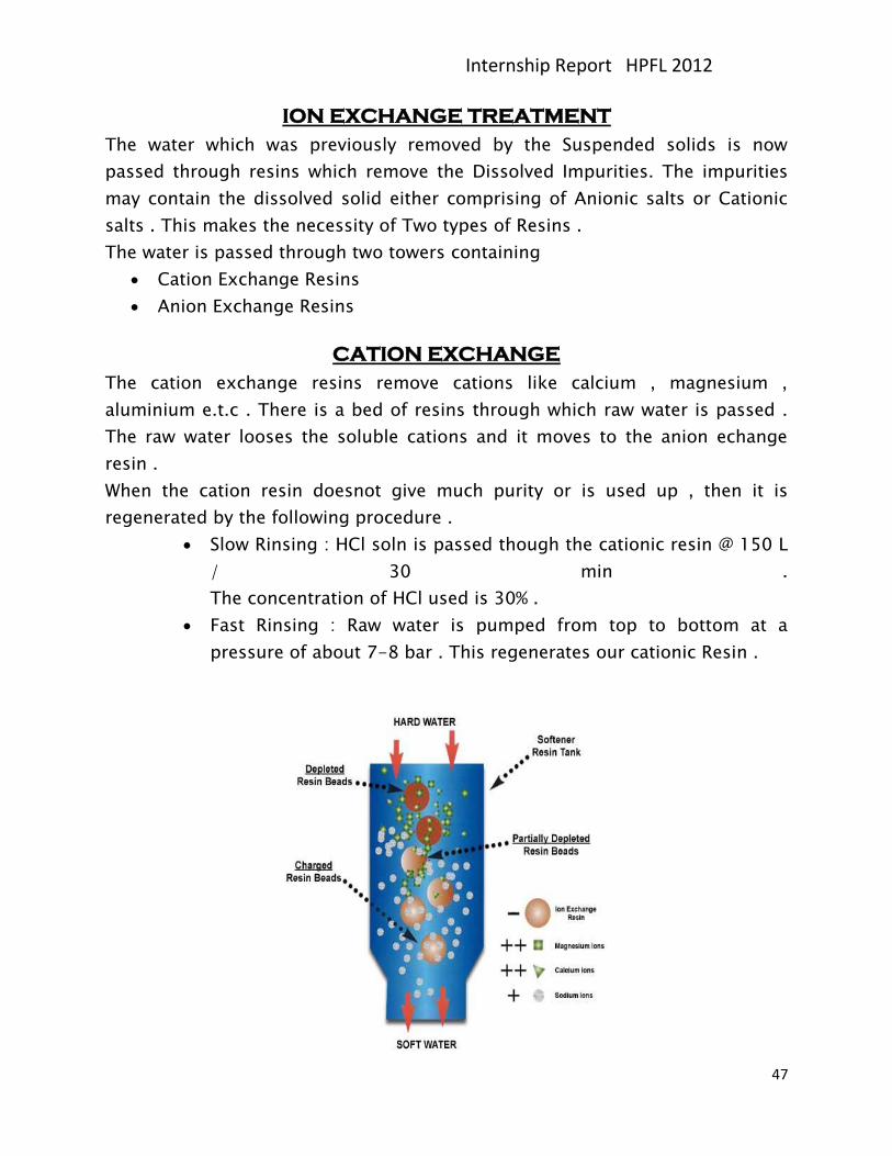
CATION EXCHANGE
The cation exchange resins remove cations like calcium , magnesium ,
aluminium e.t.c . There is a bed of resins through which raw water is passed .
The raw water looses the soluble cations and it moves to the anion echange
resin .
When the cation resin doesnot give much purity or is used up , then it is
regenerated by the following procedure .
Slow Rinsing : HCl soln is passed though the cationic resin @ 150 L
/ 30 min .
The concentration of HCl used is 30% .
Fast Rinsing : Raw water is pumped from top to bottom at a
pressure of about 7-8 bar . This regenerates our cationic Resin .
Internship Report HPFL 2012
48
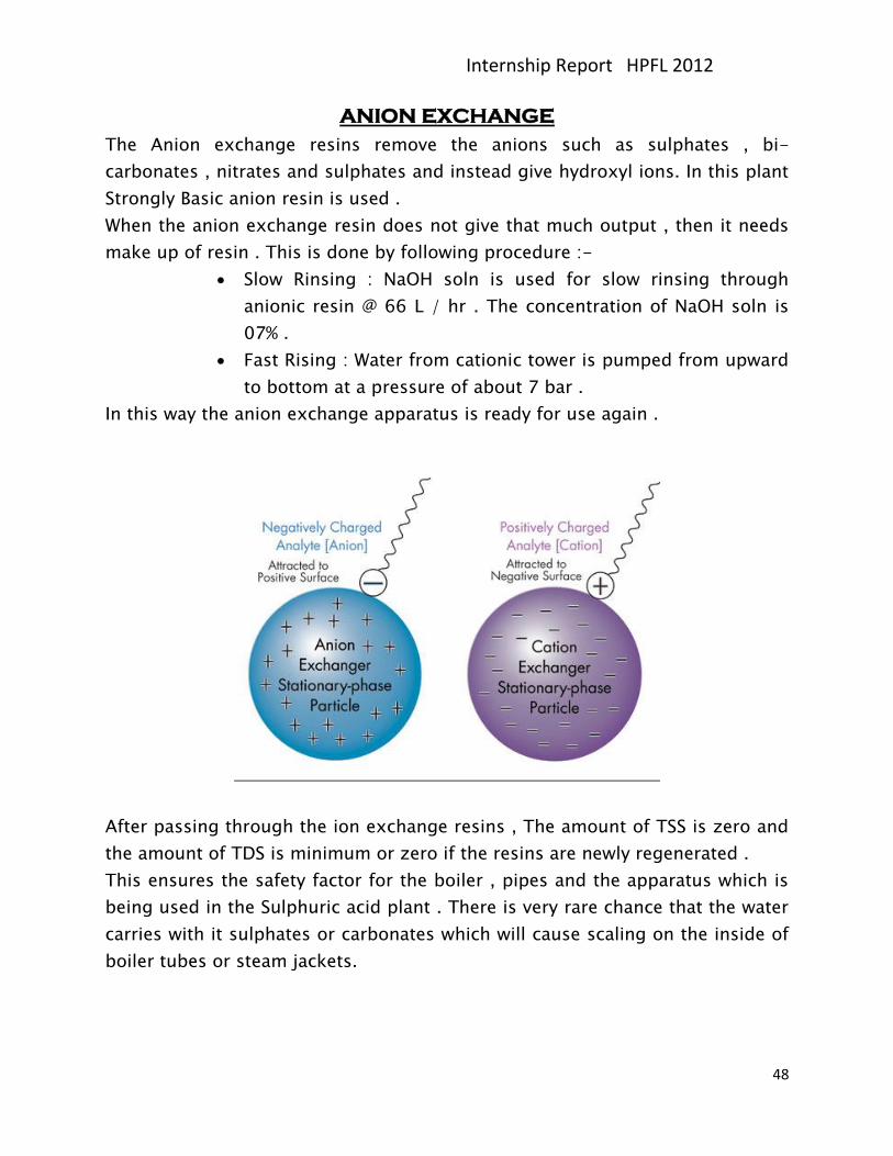
ANION EXCHANGE
The Anion exchange resins remove the anions such as sulphates , bi-
carbonates , nitrates and sulphates and instead give hydroxyl ions. In this plant
Strongly Basic anion resin is used .
When the anion exchange resin does not give that much output , then it needs
make up of resin . This is done by following procedure :-
Slow Rinsing : NaOH soln is used for slow rinsing through
anionic resin @ 66 L / hr . The concentration of NaOH soln is
07% .
Fast Rising : Water from cationic tower is pumped from upward
to bottom at a pressure of about 7 bar .
In this way the anion exchange apparatus is ready for use again .
After passing through the ion exchange resins , The amount of TSS is zero and
the amount of TDS is minimum or zero if the resins are newly regenerated .
This ensures the safety factor for the boiler , pipes and the apparatus which is
being used in the Sulphuric acid plant . There is very rare chance that the water
carries with it sulphates or carbonates which will cause scaling on the inside of
boiler tubes or steam jackets.
Internship Report HPFL 2012
49
COOLING TOWER
The water which comes back to the storage from the sulphuric acid plant and
SSP plant has gained a lot of heat and it needs to be cooled before storage . So
this water is pumped to the top of a cooling tower from where it is showered
down , while keeping a constant forced flow of air upwards which further cools
the water . In this way water and air exchange maximum heat and the water .
The temperature difference is about 11 oC. Hence the water can now be easily
stored for further use .
The storage beside the cooling tower stores this water .
Now if this water has got some acidity or basicity , it can be neutralized by
adding HCl or NaOH solution to maintain the pH of water to about 8. This is
safe value , because the materials can handle some basicity , but a small acidity
in the water can be a problem for the steel structures .
Internship Report HPFL 2012
50
SAFETY
HPFL ensures safe work environment by providing safety training to all
personnel on plant. As per the company policy all news personnel on plant
receive safety training prior taking charge of their responsibilities.
The training comprised of:
Importance of Safety at Plant
Use of Personal Protective Equipment
Use of Fire Extinguishers
IMPORTANCE OF SAFETY AT PLANT:
Safety plays a very important role in the production of the plant . As any
emergency in the plant can cause a shutdown , due to which the annual
production will decrease , which will cause a loss to the company as well as the
land.
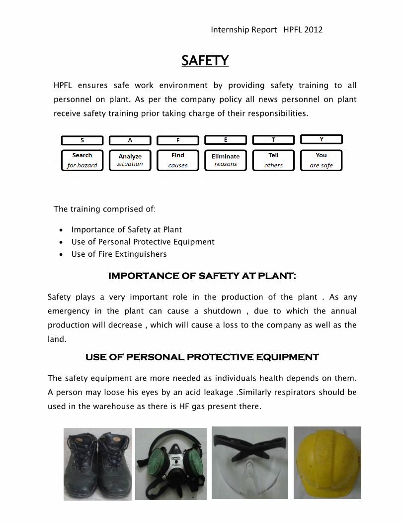
USE OF PERSONAL PROTECTIVE EQUIPMENT
The safety equipment are more needed as individuals health depends on them.
A person may loose his eyes by an acid leakage .Similarly respirators should be
used in the warehouse as there is HF gas present there.
Internship Report HPFL 2012
51
FIRE FIGHTING
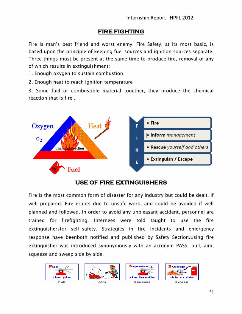
Fire is man’s best friend and worst enemy. Fire Safety, at its most basic, is
based upon the principle of keeping fuel sources and ignition sources separate.
Three things must be present at the same time to produce fire, removal of any
of which results in extinguishment:
1. Enough oxygen to sustain combustion
2. Enough heat to reach ignition temperature
3. Some fuel or combustible material together, they produce the chemical
reaction that is fire .
USE OF FIRE EXTINGUISHERS
Fire is the most common form of disaster for any industry but could be dealt, if
well prepared. Fire erupts due to unsafe work, and could be avoided if well
planned and followed. In order to avoid any unpleasant accident, personnel are
trained for firefighting. Internees were told taught to use the fire
extinguishersfor self-safety. Strategies in fire incidents and emergency
response have beenboth notified and published by Safety Section.Using fire
extinguisher was introduced synonymously with an acronym PASS; pull, aim,
squeeze and sweep side by side.
Internship Report HPFL 2012
52
ANALYSIS LAB
Following tests are performed in the lab to ensure the quality standards of the
company.
Phosphate Rock Test
ROP Test
ROP Test after curing
SSP Product Test
Sulphur Test
Water hardness Test
Water pH Test
SO2 gas Test
SO3 gas Test
Sulphuric Acid Test


![[ This report is NOT for Public Discussion ] INTERNSHIP REPORT : …ensearch.org/.../uploads/2012/04/2004-Internship-Report.pdf · 2017. 1. 14. · Undergraduate Internship: You-Han](https://img.pdfslide.us/doc/110x75/611747fc4585bd6cf00b5257/-this-report-is-not-for-public-discussion-internship-report-2017-1-14.jpg)


![[Internship Report] folder... · Web view[Internship Report] [Internship Report] 3 [Internship Report] Prince Mohammed Bin Fahd University College of Computer Engineering and Science](https://img.pdfslide.us/doc/110x75/5adbc5e37f8b9add658e5f6e/internship-report-folderweb-viewinternship-report-internship-report-3-internship.jpg)