Embed Size (px)
Citation preview

Internet of Things Group
Sensor Circuits IBM WITI Hackathon

Internet of Things Group Intel Confidential
Intel® Edison Block Diagram

Internet of Things Group 3
Edison Arduino Mapping ADC INPUTS
VCC & GND
UART
GPIO + PWM + SPI
I2C

Internet of Things Group
Digital Input / Output • These are used to control single digital singles & can be set to either output a signal or receive a signal.
• Uses – reading input signals like switches, controlling outputs LEDs, Motors, Relays
Analogue Digital Converter • 12 bit accuracy, 6 channels available through Arduino pins
• ADC sampling at 5kHz- take a ‘snapshot’ of the voltage level every 200uS
PWM – Pseudo Analogue Outputs • PWM stands for Pulse Width Modulation
• Used to get analogue results by digital means
• Sends pulses of power to simulate voltage
• The duration of high power is know as the ‘Pulse Width’
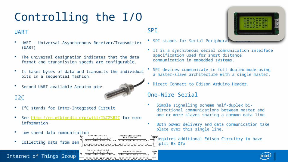
Controlling The I/O
Internet of Things Group
UART UART - Universal Asynchronous Receiver/Transmitter (UART)
The universal designation indicates that the data format and transmission speeds are configurable.
It takes bytes of data and transmits the individual bits in a sequential fashion.
Second UART available Arduino pins
I2C
I²C stands for Inter-Integrated Circuit
See http://en.wikipedia.org/wiki/I%C2%B2C for more information.
Low speed data communication
Collecting data from sensors and other devices.
Available through Arduino pins
SPI
SPI stands for Serial Peripheral Interface
It is a synchronous serial communication interface specification used for short distance communication in embedded systems.
SPI devices communicate in full duplex mode using a master-slave architecture with a single master.
Direct Connect to Edison Arduino Header.
One-Wire Serial
Simple signalling scheme half-duplex bi-directional communications between master and one or more slaves sharing a common data line.
Both power delivery and data communication take place over this single line.
Requires additional Edison Circuitry to have split Rx &Tx
Controlling the I/O

Internet of Things Group 6
Useful Circuits – One-Wire Serial implementation VCC
GND
Sensor

Internet of Things Group 7
Controlling a DC Motor – Drive Circuit
L293DN
Motor Control is a combination of a drive circuit & PWM outputs to control speed.
Circuit shown can drive Motor in both directions.
GPIOs perform control function for Battery Voltage.
Making Pin 2 high and Pin 3 low will rotate the DC motor in one direction.
Making Pin 2 low and Pin 2 high will rotatethe DC motor in the opposite direction.

Placeholder Footer Copy / BU Logo or Name Goes Here