Embed Size (px)
Citation preview
Proceedings of the 4th International Workshop on
Feature-Oriented Software Development (FOSD’12)
September 24-25, 2012 – Dresden, Germany
Editors:Ina Schaefer (University of Braunschweig, DE)Thomas Thum (University of Magdeburg, DE)
Proceedings published online in theACM Digital Library
www.acm.org
Printed proceedings sponsored byMetop GmbH
www.metop.de

Held in conjunction with
the 5th International Conference of Software Language Engineering (SLE’12) and
the 11th International Conference on Generative Programming and Component Engineering (GPCE’12)
sponsored by
i
The Association for Computing Machinery2 Penn Plaza, Suite 701
New York, New York 10121-0701U.S.A.
ACM COPYRIGHT NOTICE. Copyright c© 2012 by the Associationfor Computing Machinery, Inc. Permission to make digital or hardcopies of part or all of this work for personal or classroom use is grantedwithout fee provided that copies are not made or distributed for profitor commercial advantage and that copies bear this notice and the fullcitation on the first page. Copyrights for components of this workowned by others than ACM must be honored. Abstracting with creditis permitted. To copy otherwise, to republish, to post on servers, orto redistribute to lists, requires prior specific permission and/or a fee.Request permissions from Publications Dept., ACM, Inc., fax +1 (212)869-0481, or [email protected].
For other copying of articles that carry a code at the bottom of thefirst or last page, copying is permitted provided that the per-copyfee indicated in the code is paid through the Copyright ClearanceCenter, 222 Rosewood Drive, Danvers, MA 01923, +1-978-750-8400,+1-978-750-4470 (fax).
Notice to Past Authors of ACM-Published Articles ACM intends tocreate a complete electronic archive of all articles and/or other materialpreviously published by ACM. If you have written a work that waspreviously published by ACM in any journal or conference proceedingsprior to 1978, or any SIG Newsletter at any time, and you do NOTwant this work to appear in the ACM Digital Library, please [email protected], stating the title of the work, the author(s), andwhere and when published.
ACM ISBN: 978-1-4503-1309-4
ii

Program Committee
Sven Apel (University of Passau, DE)Joanne Atlee (University of Waterloo, CA)
Maider Azanza (University of the Basque Country, ES)Don Batory (University of Texas at Austin, US)
Paulo Borba (University of Pernambuco, BR)Jan Bosch (Chalmers University of Technology, SE)
Goetz Botterweck (Lero, IE)Manfred Broy (Technische Universitat Munich, DE)Dave Clarke (Katholieke Universiteit Leuven, BE)
Martin Erwig (Oregon State University, US)Kathi Fisler (Worcester Polytechnic Institute, US)
Alessandro Garcia (PUC-Rio, BR)Jeff Gray (University of Alabama, US)
Florian Heidenreich (Technische Universitat Dresden, DE)Patrick Heymans (University of Namur, BE)
Christian Kastner (University of Marburg, DE)Thomas Leich (Metop, DE)
Christian Lengauer (University of Passau, DE)Malte Lochau (Technische Universitat Braunschweig, DE)
Christian Prehofer (Fraunhofer ESK, DE)Rick Rabiser (Johannes Kepler University, AT)
Stephan Reiff-Marganiec (University of Leicester, UK)Bernhard Rumpe (RWTH Aachen, DE)
Stefan Sobernig (Vienna Uni of Economics and Business, AT)Maurice Ter Beek (Consiglio Nazionale delle Ricerche, IT)
Ken Turner (University of Stirling, UK)
iii
Preface
Feature orientation is an emerging paradigm of software development.It supports the largely automatic generation of large software systemsfrom a set of units of functionality called features. The key idea offeature-oriented software development (FOSD) is to emphasize thesimilarities of a family of software systems for a given applicationdomain (e.g., database systems, banking software, text processingsystems) with the goal of reusing software artifacts among the familymembers. Features distinguish different members of the family. Achallenge in FOSD is that a feature does not map cleanly to an isolatedmodule of code. Rather it may affect (“cut across”) many componentsand documents of a software system. Research on FOSD has shownthat the concept of features pervades all phases of the software lifecycle and requires a proper treatment in terms of analysis, design, andprogramming techniques, methods, languages, and tools, as well asformalisms and theory.
The primary goal of the 4th International Workshop on Feature-OrientedSoftware Development is to foster and strengthen the collaboration be-tween the researchers who work in the field of FOSD or in the relatedfields of software product lines, service-oriented architecture, model-driven engineering and feature interactions. The focus of FOSD’12 willbe on discussions, rather than on presenting technical content only. Bothworkshop days start with a keynote by leading researchers in FOSD.Mira Mezini will talk about programming language concepts for FOSDand Salvador Trujillo is going to share experiences in applying FOSD tooffshore wind power and railways. These keynotes will be an excellentstart up for discussions on historical perspectives, current issues, andvisions of FOSD.
iv
Keynotes
Programming Language Concepts for Feature-Oriented Soft-ware DevelopmentMira Mezini, Darmstadt University of Technology, Germany
Object-oriented concepts of classes, inheritance and subtype polymor-phism are praised for supporting the design of software that is open forextensions but closed for modifications. Yet, they fail to properly sup-port feature encapsulation and extensibility. This has motivated workon late bound classes, advanced module concepts, and aspect-orientedprogramming. In the talk, I will present some of the work I have beendoing in this space, specifically related to virtual and dependent classes,aspect-oriented and event-driven programming and will discuss theusefulness of these concepts for supporting feature-oriented softwaredevelopment.
FOSD-Engineering beyond Code: Experiences from OffshoreWind Power and RailwaysSalvador Trujillo, IKERLAN Research Centre, Spain
Feature-Oriented Software Development (FOSD) is a software productline paradigm where products result from composing a set of units offunctionality called features. Code-centric approaches, where a prod-uct’s source code is produced from the automated composition of fea-tures, dominated FOSD in early stages. Recently, research on FOSDhas shown that the concept of features pervades all phases of the soft-ware life cycle and requires a proper treatment in terms of analysis,design, and programming techniques, methods, languages, and tools, aswell as formalisms and theory. This presentation revisits code compo-sition approaches and looks at models as a mechanism to attain higherabstraction levels. This is necessary for FOSD to scale towards largersoftware and systems engineering and to broaden the scope of the FOSDengineering lifecycle from software to systems engineering. Software ar-tifacts become just another piece of the entire system. These ideas areillustrated with our experience FOSD-engineering industrial systems inpractice for offshore wind power and railways domains.
v
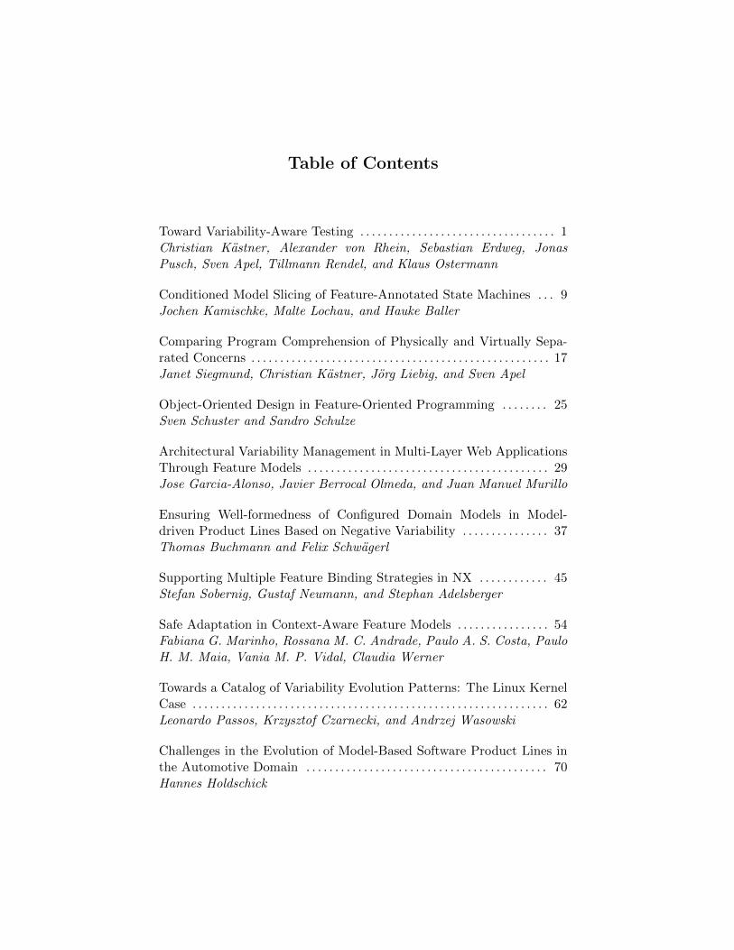
Table of Contents
Toward Variability-Aware Testing . . . . . . . . . . . . . . . . . . . . . . . . . . . . . . . . . . 1Christian Kastner, Alexander von Rhein, Sebastian Erdweg, JonasPusch, Sven Apel, Tillmann Rendel, and Klaus Ostermann
Conditioned Model Slicing of Feature-Annotated State Machines . . . 9Jochen Kamischke, Malte Lochau, and Hauke Baller
Comparing Program Comprehension of Physically and Virtually Sepa-rated Concerns . . . . . . . . . . . . . . . . . . . . . . . . . . . . . . . . . . . . . . . . . . . . . . . . . . . . 17Janet Siegmund, Christian Kastner, Jorg Liebig, and Sven Apel
Object-Oriented Design in Feature-Oriented Programming . . . . . . . . 25Sven Schuster and Sandro Schulze
Architectural Variability Management in Multi-Layer Web ApplicationsThrough Feature Models . . . . . . . . . . . . . . . . . . . . . . . . . . . . . . . . . . . . . . . . . . 29Jose Garcia-Alonso, Javier Berrocal Olmeda, and Juan Manuel Murillo
Ensuring Well-formedness of Configured Domain Models in Model-driven Product Lines Based on Negative Variability . . . . . . . . . . . . . . . 37Thomas Buchmann and Felix Schwagerl
Supporting Multiple Feature Binding Strategies in NX . . . . . . . . . . . . 45Stefan Sobernig, Gustaf Neumann, and Stephan Adelsberger
Safe Adaptation in Context-Aware Feature Models . . . . . . . . . . . . . . . . 54Fabiana G. Marinho, Rossana M. C. Andrade, Paulo A. S. Costa, PauloH. M. Maia, Vania M. P. Vidal, Claudia Werner
Towards a Catalog of Variability Evolution Patterns: The Linux KernelCase . . . . . . . . . . . . . . . . . . . . . . . . . . . . . . . . . . . . . . . . . . . . . . . . . . . . . . . . . . . . . . 62Leonardo Passos, Krzysztof Czarnecki, and Andrzej Wasowski
Challenges in the Evolution of Model-Based Software Product Lines inthe Automotive Domain . . . . . . . . . . . . . . . . . . . . . . . . . . . . . . . . . . . . . . . . . . 70Hannes Holdschick
vi

vii
Toward Variability-Aware Testing
Christian KästnerPhilipps University Marburg
Alexander von RheinUniversity of Passau
Sebastian Erdweg andJonas Pusch
Philipps University Marburg
Sven ApelUniversity of Passau
Tillmann Rendel andKlaus Ostermann
Philipps University Marburg
ABSTRACT
We investigate how to execute a unit test for all products of a productline without generating each product in isolation in a brute-forcefashion. Learning from variability-aware analyses, we (a) designand implement a variability-aware interpreter and, alternatively, (b)reencode variability of the product line to simulate the test cases witha model checker. The interpreter internally reasons about variability,executing paths not affected by variability only once for the wholeproduct line. The model checker achieves similar results by reusingpowerful off-the-shelf analyses. We experimented with a prototypeimplementation for each strategy. We compare both strategies anddiscuss trade-offs and future directions. In the long run, we aim atfinding an efficient testing approach that can be applied to entireproduct lines with millions of products.
1. INTRODUCTION
Analysis of software product lines has attracted much attention byresearchers [26]. The addressed key problem is that traditional analy-sis methods (type checking, static analysis, model checking, testing,and so forth) target only individual programs, whereas a productline with n optional compile-time features gives rise to O(2n) dis-tinct configurations, and thus O(2n) distinct products. Traditionally,obtaining an analysis result for the entire product line (e.g., whetherevery product is well typed) would require to analyze each product inisolation, in a brute-force fashion. Since a brute-force approach doesnot scale due to the huge configuration space, practitioners resort tosampling strategies [5,20–22]: They analyze only a few products cur-rently produced, they analyze a few randomly selected products, orthey analyze a relatively small number of products selected by somecoverage criterion, such as t-way feature coverage. However, sam-pling cannot yield reliable analysis results for the entire product line.
Recently, researchers have investigated alternative strategies toanalyze entire product lines without looking at the generated code ofeach product. We call analyses following these strategies variability-
aware analysis (or family-based analysis [26]), because they takethe variability of the product-line implementation into account dur-ing analysis. Roughly speaking, the idea is to analyze a generator(the product-line implementation itself together with configuration
Permission to make digital or hard copies of all or part of this work forpersonal or classroom use is granted without fee provided that copies arenot made or distributed for profit or commercial advantage and that copiesbear this notice and the full citation on the first page. To copy otherwise, torepublish, to post on servers or to redistribute to lists, requires prior specificpermission and/or a fee.FOSD’12, September 24–25, 2012, Dresden, Germany.Copyright 2012 ACM 978-1-4503-1309-4/12/09 ...$5.00.
knowledge) instead of analyzing the generated products. Variability-aware analysis exploits the fact that products in a product line typ-ically are generated from a common code base and share a signif-icant amount of common code [10, 22]. When using brute forceor sampling, this common code is analyzed repeatedly. In contrast,variability-aware analyses usually perform analysis on commoncode only once, while only variable code that actually affects theanalysis result causes additional effort.
Researchers have successfully developed variability-aware anal-yses for parsing, type checking, model checking, static analysis,and theorem proving (see Sec. 5). Although testing of product lineshas received significant attention, researchers have concentrated onsampling strategies [5, 20, 21], on test suite reduction [15, 24], andon test generation [24, 28]. In all these approaches, though, individ-ual tests are still executed on generated products, one by one. Tothe best of our knowledge, there is no notion of variability-aware
test execution, where a test is run on an entire product line withoutgenerating individual products.
Our goal is to transfer experience from existing variability-awareanalyses to product-line testing. We want to execute a test case (e.g.,
a unit test) in all configurations of a product line, without actually
generating a product for each configuration. In this workshop paper,we explore early steps in this direction. In line with extended mech-anisms used in variability-aware analyses, we build a variability-
aware interpreter to execute a test case in all configurations of aproduct line in parallel (which resembles mixed concrete/symbolicexecution). Additionally, we explore an alternative strategy basedon variability encodings and off-the-shelf analysis tools, in our case,JavaPathfinder (JPF) [29] and the extension jpf-bdd [30].
Specifically, our contributions are: We generalize strategies toimplement variability-aware analyses into white-box and black-boxstrategies, which was only implicit in prior work. We design and im-plement a variability-aware interpreter for a WHILE language (whitebox). We apply JPF for variability-aware testing (black box). Finally,while we cannot yet make claims about scalability to real-worldproblems, we discuss trade-offs and limitations, and we outlineresearch directions.
We want to encourage researchers to investigate testing of wholeproduct lines without the usual sampling strategies. We are still inan early exploration stage toward variability-aware testing. Here,we present initial ideas and early experiences with prototypes andcases studies. We appreciate any feedback and ideas.
2. VARIABILITY-AWARE ANALYSIS
Before we discuss test-case execution in product lines, we brieflyintroduce variability-aware analysis in general, from which we thenadopt many concepts. We start with the general goal, outline howwe represent variability, and discuss two common implementation
1
Product Line
(AST with Variability)
Results with
Variability
(For all Products)
Result
(For one Product)
(4a) configure
(4b) aggregate
(1) configure
(2) traditional
analysis
(3) variability-aware
analysis
Product
(AST without
Variability)
Figure 1: Variability-aware vs. brute-force analysis
1 case class Opt[T](pc: FeatureExpr, value: T)
23 abstract class Cond[T]
4 case class One[T](value: T) extends Cond[T]
5 case class Choice[T](pc: FeatureExpr, a: Cond[T], b: Cond[T])
extends Cond[T]
67 def condFlatMap[T, U](a: Cond[T], vctx: FeatureExpr,
8 fun: (FeatureExpr, T) => Cond[U]): Cond[U] = a match {
9 case One(t) => fun(vctx, t)
10 case Choice(pc, a, b) =>
11 Choice(pc, condFlatMap(a, vctx∧pc, fun),
12 condFlatMap(b, vctx∧¬pc, fun))
13 }
Figure 2: Variability structures and core utility functions imple-
mented with Scala
strategies.We can explain variability-aware analysis with the process pattern
illustrated in Figure 1. Instead of repeatedly generating a product(Step 1) and analyzing each product with a traditional analysis (Step2), we want to analyze the entire product line without generating indi-vidual products (Step 3). Variability-aware analysis should producea result that describes the entire product line. The result explainsin which configuration which specific property holds (e.g., “all con-figurations with feature FOO are ill typed, all other configurationsare well typed”). From this analysis result, we are able to deducethe properties that we would establish for an individual productwith the traditional analysis (Step 4a). Alternatively, by applying thetraditional analysis in a brute-force fashion to all products, we couldaggregate the individual properties to describe the entire productline (Step 4b). While the output should be equivalent, we expectthe variability-aware analysis (Step 3) to be much faster than thebrute-force strategy (repeating Steps 1, 2, and 4b). In this paper, wewant to apply this concept also to testing.
2.1 Variability representation
To perform variability-aware analysis, we need a structural represen-tation of the product-line implementation that contains all compile-time variability. In our work, we encode compile-time variabilitydirectly in abstract syntax trees (ASTs) with presence conditions. Apresence condition is a propositional formula over features of theproduct line that yields true iff the AST element (i.e, the correspond-ing code fragment) should be included in the product for a givenconfiguration.
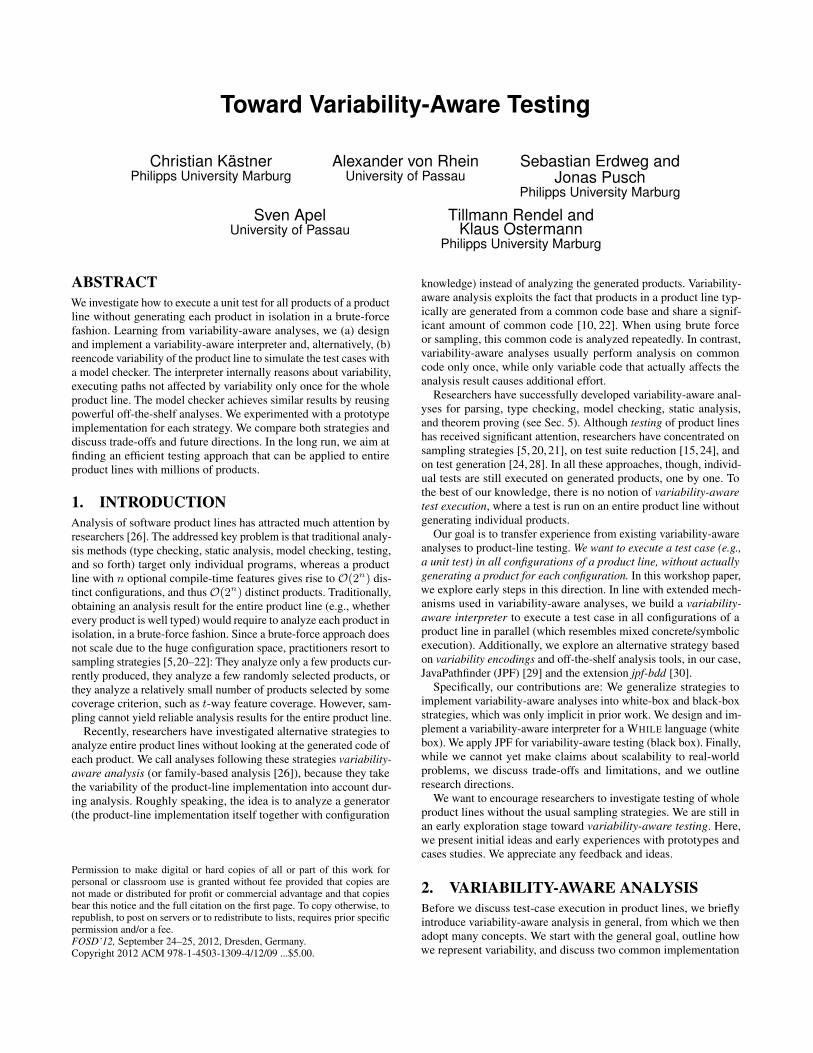
We manage variability with two constructs, as illustrated withScala code in Figure 2: First, program elements can be optional(Opt[T] for elements of type T). An optional element is guarded bya propositional presence condition, which is represented by typeFeatureExpr. Second, type Cond[T] encodes conditional elements,that is, elements that differ between configurations. We have eitherone element (One[T]) or a choice between two elements (Choice[T])depending on a presence condition. Since choices can be nested,
1 abstract class Stmt
2 case class Block(s: List[Opt[Stmt]]) extends Stmt
3 case class Assign(n: String, e: Cond[Expr]) extends Stmt
4 case class If(e: Cond[Expr], s: Stmt) extends Stmt
5 case class While(e: Cond[Expr], s: Stmt) extends Stmt
67 abstract class Expr
8 case class Var(name: String) extends Expr
9 case class Lit(value: Int) extends Expr
10 ...
Figure 3: Abstract syntax of a WHILE language with variability
implemented in Scala
1 a = 1;
2 #ifdef FOO
3 b = true;
4 #endif5 if (a < 3)
6 a = a + 1;
7 #ifndef FOO
8 b = false;
9 #endif10 if (b)
11 a = 0;
12 #ifdef BAR
13 a = 0;
14 #endif1516 b =
17 #if BAR || FOO
18 true
19 #else20 false
21 #endif22 ;
AST Assign“a”
LitOne
Opt true
Assign“b”
trueOne
Opt FOO
If
“a”
Opt trueVarOne
Assign …
…
Assign“b”
Choice BARvFOOOpt true true
false
1
Lit
Lit
Lit
One
One
Assign“b”
falseOne
Opt ¬FOOLit
3Lit
<
Figure 4: Example program with variability and corresponding
AST (choice nodes shown with black background color)
we can express multiple alternative elements. For example, we canexpress that variable v has value 1 if feature X is selected, andvalue 2 if feature Y but not Z is selected, and value −1 in all othercases: v=Choice(X, One(1), Choice(Y∧¬Z, One(2), One(-1))).1 Op-tional elements are typically used inside lists when 0..n elementsare supported (e.g., a list of optional statements can contain no,one, or multiple statements in each configuration), whereas con-ditional elements are used when exactly one element is requiredin each configuration (e.g., an assignment always has exactly oneright-hand-side expression).
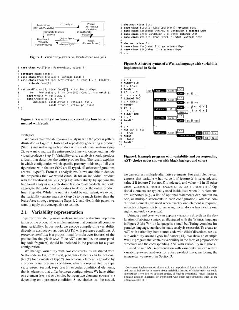
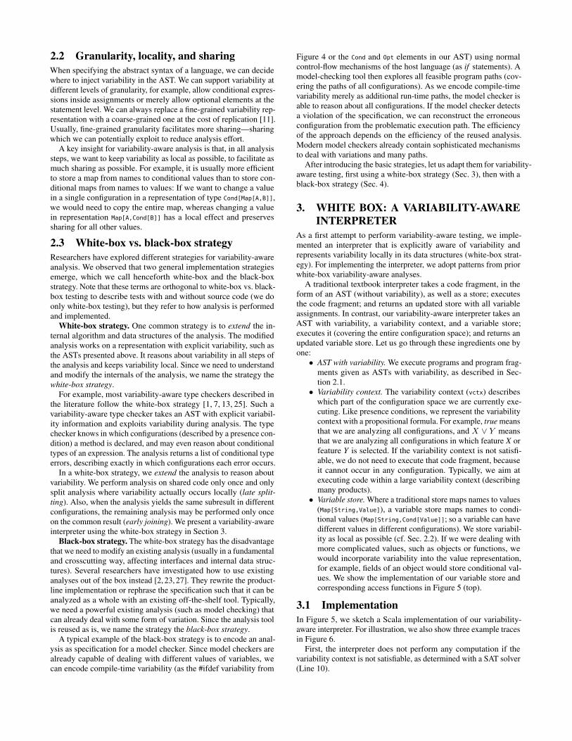
Using Opt and Cond, we can express variability directly in the dec-laration of abstract syntax, as illustrated with the WHILE languagein Figure 3 (the WHILE language is a small but Turing-complete im-perative language, standard in static-analysis research). To create anAST with variability from source code with #ifdef directives, we useour variability-aware TypeChef parser [14]. We show an exampleWHILE program that contains variability in the form of preprocessordirectives and the corresponding AST with variability in Figure 4.
Based on our AST representation with variability, we can realizevariability-aware analyses for entire product lines, including theinterpreter we present in Section 3.
1Our current implementation allows arbitrary propositional formulas in choice nodes
and uses a SAT solver to reason about variability. Instead of choice trees, we couldalternatively store lists of optional entries, or encode conditional values similar toBoolean decision diagrams, or experiment with other representations, such as theChoice calculus [11].
2
2.2 Granularity, locality, and sharing
When specifying the abstract syntax of a language, we can decidewhere to inject variability in the AST. We can support variability atdifferent levels of granularity, for example, allow conditional expres-sions inside assignments or merely allow optional elements at thestatement level. We can always replace a fine-grained variability rep-resentation with a coarse-grained one at the cost of replication [11].Usually, fine-grained granularity facilitates more sharing—sharingwhich we can potentially exploit to reduce analysis effort.
A key insight for variability-aware analysis is that, in all analysissteps, we want to keep variability as local as possible, to facilitate asmuch sharing as possible. For example, it is usually more efficientto store a map from names to conditional values than to store con-ditional maps from names to values: If we want to change a valuein a single configuration in a representation of type Cond[Map[A,B]],we would need to copy the entire map, whereas changing a valuein representation Map[A,Cond[B]] has a local effect and preservessharing for all other values.
2.3 White-box vs. black-box strategy
Researchers have explored different strategies for variability-awareanalysis. We observed that two general implementation strategiesemerge, which we call henceforth white-box and the black-boxstrategy. Note that these terms are orthogonal to white-box vs. black-box testing to describe tests with and without source code (we doonly white-box testing), but they refer to how analysis is performedand implemented.
White-box strategy. One common strategy is to extend the in-ternal algorithm and data structures of the analysis. The modifiedanalysis works on a representation with explicit variability, such asthe ASTs presented above. It reasons about variability in all steps ofthe analysis and keeps variability local. Since we need to understandand modify the internals of the analysis, we name the strategy thewhite-box strategy.
For example, most variability-aware type checkers described inthe literature follow the white-box strategy [1, 7, 13, 25]. Such avariability-aware type checker takes an AST with explicit variabil-ity information and exploits variability during analysis. The typechecker knows in which configurations (described by a presence con-dition) a method is declared, and may even reason about conditionaltypes of an expression. The analysis returns a list of conditional typeerrors, describing exactly in which configurations each error occurs.
In a white-box strategy, we extend the analysis to reason aboutvariability. We perform analysis on shared code only once and onlysplit analysis where variability actually occurs locally (late split-
ting). Also, when the analysis yields the same subresult in differentconfigurations, the remaining analysis may be performed only onceon the common result (early joining). We present a variability-awareinterpreter using the white-box strategy in Section 3.
Black-box strategy. The white-box strategy has the disadvantagethat we need to modify an existing analysis (usually in a fundamentaland crosscutting way, affecting interfaces and internal data struc-tures). Several researchers have investigated how to use existinganalyses out of the box instead [2, 23, 27]. They rewrite the product-line implementation or rephrase the specification such that it can beanalyzed as a whole with an existing off-the-shelf tool. Typically,we need a powerful existing analysis (such as model checking) thatcan already deal with some form of variation. Since the analysis toolis reused as is, we name the strategy the black-box strategy.
A typical example of the black-box strategy is to encode an anal-ysis as specification for a model checker. Since model checkers arealready capable of dealing with different values of variables, wecan encode compile-time variability (as the #ifdef variability from
Figure 4 or the Cond and Opt elements in our AST) using normalcontrol-flow mechanisms of the host language (as if statements). Amodel-checking tool then explores all feasible program paths (cov-ering the paths of all configurations). As we encode compile-timevariability merely as additional run-time paths, the model checker isable to reason about all configurations. If the model checker detectsa violation of the specification, we can reconstruct the erroneousconfiguration from the problematic execution path. The efficiencyof the approach depends on the efficiency of the reused analysis.Modern model checkers already contain sophisticated mechanismsto deal with variations and many paths.
After introducing the basic strategies, let us adapt them for variability-aware testing, first using a white-box strategy (Sec. 3), then with ablack-box strategy (Sec. 4).
3. WHITE BOX: A VARIABILITY-AWARE
INTERPRETER
As a first attempt to perform variability-aware testing, we imple-mented an interpreter that is explicitly aware of variability andrepresents variability locally in its data structures (white-box strat-egy). For implementing the interpreter, we adopt patterns from priorwhite-box variability-aware analyses.
A traditional textbook interpreter takes a code fragment, in theform of an AST (without variability), as well as a store; executesthe code fragment; and returns an updated store with all variableassignments. In contrast, our variability-aware interpreter takes anAST with variability, a variability context, and a variable store;executes it (covering the entire configuration space); and returns anupdated variable store. Let us go through these ingredients one byone:
• AST with variability. We execute programs and program frag-ments given as ASTs with variability, as described in Sec-tion 2.1.
• Variability context. The variability context (vctx) describeswhich part of the configuration space we are currently exe-cuting. Like presence conditions, we represent the variabilitycontext with a propositional formula. For example, true meansthat we are analyzing all configurations, and X ∨ Y meansthat we are analyzing all configurations in which feature X orfeature Y is selected. If the variability context is not satisfi-able, we do not need to execute that code fragment, becauseit cannot occur in any configuration. Typically, we aim atexecuting code within a large variability context (describingmany products).
• Variable store. Where a traditional store maps names to values(Map[String,Value]), a variable store maps names to condi-tional values (Map[String,Cond[Value]]; so a variable can havedifferent values in different configurations). We store variabil-ity as local as possible (cf. Sec. 2.2). If we were dealing withmore complicated values, such as objects or functions, wewould incorporate variability into the value representation,for example, fields of an object would store conditional val-ues. We show the implementation of our variable store andcorresponding access functions in Figure 5 (top).
3.1 Implementation
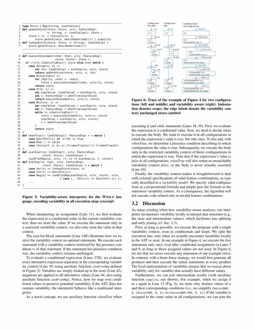
In Figure 5, we sketch a Scala implementation of our variability-aware interpreter. For illustration, we also show three example tracesin Figure 6.
First, the interpreter does not perform any computation if thevariability context is not satisfiable, as determined with a SAT solver(Line 10).
3
1 type Store = Map[String, Cond[Value]]
2 def updateStore(store: Store, vctx: FeatureExpr,
3 n: String, v: Cond[Value]): Store =
4 store + (n -> Choice(vctx, v,
5 store.getOrElse(n, One(VUndefined())) ).simplify)
6 def lookupStore(store: Store, n: String): Cond[Value] =
7 store.getOrElse(n, One(VUndefined()))
8 def executeStatement(stmt: Stmt, vctx: FeatureExpr,
9 store: Store): Store =
10 if (!vctx.isSatisfiable()) store else stmt match {
11 case Assign(n, e) =>
12 val rhs: Cond[Value] = evalExpr(e, vctx, store)
13 return updateStore(store, vctx, n, rhs)
14 case Block(stmts) =>
15 for (Opt(fs, stmt) <- stmts)
16 store = executeStatement(stmt, vctx∧fs, store)
17 return store
18 case If(e, s) =>
19 val exprValue: Cond[Value] = evalExpr(e, vctx, store)
20 val x: FeatureExpr = whenTrue(exprValue)
21 return executeStatement(s, vctx∧x, store)
22 case While(e, s) =>
23 var exprValue: Cond[Value] = evalExpr(e, vctx, store)
24 var x: FeatureExpr = whenTrue(exprValue)
25 while (x.isSatisfiable()) {
26 store = executeStatement(s, vctx∧x, store)
27 exprValue = evalExpr(e, vctx, store);
28 x = whenTrue(exprValue)
29 }
30 return store
31 }
32 def whenTrue(v: Cond[Value]): FeatureExpr = v match {
33 case One(VInt(v)) if (v!=0) => True
34 case One(_) => False
35 case Choice(f, a, b) => (f∧whenTrue(a))∨(¬f∧whenTrue(b))
36 }
37 def evalExpr(ce: Cond[Expr], vctx: FeatureExpr,
38 store: Store): Cond[Value] =
39 condFlatMap(ce, vctx, (f, e) => evalExpr(e, f, store))
40 def evalExpr(e: Expr, vctx: FeatureExpr,
41 store: Store): Cond[Value] = e match {
42 case Var(n) => lookupStore(store, n)
43 case Int(v) => One(VInt(v))
44 case Neg(e) => condFlatMap(evalExpr(e, vctx, store), vctx,
45 { case (_, VInt(v)) => One(VInt(-v)) })
46 ...
47 }
Figure 5: Variability-aware interpreter for the WHILE lan-
guage, encoding variability in all execution steps (excerpt)
When interpreting an assignment (Line 11), we first evaluatethe expression to a conditional value in the current variability con-text, then we store the value. If we execute the statement only ina restricted variability context, we also only store the value in thatcontext.
The case for block statements (Line 14ff) illustrates how we re-strict the variability context on optional statements. We execute eachstatement with a variability context restricted by the presence con-dition fs of that statement. If the statement has presence conditiontrue, the variability context remains unchanged.
To evaluate a conditional expression (Lines 37ff), we evaluateevery alternative expression separately in the corresponding variabil-ity context (Line 39; using auxiliary function condFlatMap definedin Figure 2). Variables are simply looked up in the store (Line 42),negations are applied to all alternative values (Line 44; also usingauxiliary function condFlatMap). Notice, how we map over condi-tional values to preserve potential variability; if the AST does notcontain variability, the interpreter behaves like a traditional inter-preter.
As a novel concept, we use auxiliary function whenTrue when
a=1
a=1
a=1
b=true
b=true
if (a<3)
a=2
b=true
a=a+1
if (b)
a=0
b=true
a=0
a=1
a=1
if (a<3)
a=2
a=a+1
a=2
b=false
b=false
if (b)
a=1
true: a=1
a=1
b=Choice(FOO, true, ⊥)
FOO: b=true
true: if (a<3)
a=2
b=Choice(FOO, true, ⊥)
true: a=a+1
a=2
b=Choice(FOO, true, false)
¬FOO: b=false
true: if (b)
a=Choice(FOO, 0, 2)
b=Choice(FOO, true, false)
FOO: a=0
a=Choice(BARvFOO, 0, 2)
b=Choice(FOO, true, false)
BAR: a=0
Configuration
FOO, BAR
Configuration
BAR Variability-Aware
(all configurations)
a=0
b=true
b = true
a=0
b=true
b = true
a=Choice(BARvFOO, 0, 2)
b=Choice(BARvFOO, true, false)
true: H = …
a=0
b=false
a=0
a=0
b=false
a=0
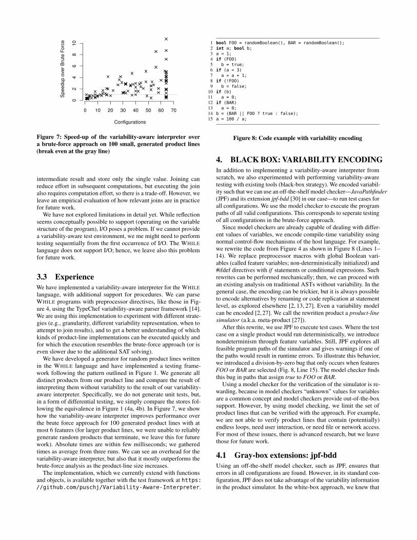
Figure 6: Trace of the example of Figure 4 for two configura-
tions (left and middle) and variability aware (right). Indenta-
tion denotes scope; the edge labels denote the variability con-
text; unchanged stores omitted
executing if and while statements (Lines 18–30). First, we evaluatethe expression to a conditional value. Now, we need to decide whento execute the body. We want to execute it in all configurations inwhich the expression’s value is true, but only once. To this end, withwhenTrue, we determine a presence condition describing in whichconfigurations the value is true. Subsequently, we execute the bodyonly in the restricted variability context of those configurations inwhich the expression is true. Note that if the expression’s value isfalse in all configurations, whenTrue will also return an unsatisfiablevariability context false, so the body is never actually executed(Line 10).
Finally, the variability context makes it straightforward to dealwith external specifications of valid feature combinations, as typi-cally described in a variability model. We specify valid configura-tions as a propositional formula and simply pass the formula as theoutermost variability context. As a consequence, the algorithm willnot execute code related only to invalid feature combinations.
3.2 Discussion
As many existing white-box variability-aware analyses, our inter-preter incorporates variability locally in internal data structures (e.g.,the store and intermediate values), which facilitates late splittingand early joining (cf. Sec. 2.3).
First, as long as possible, we execute the program with a singlevariability context, even in conditionals and loops. We split theexecution late, only when we actually encounter variability locallyin the AST or store. In our example in Figure 4, we execute the firststatements only once, even after conditional assignments in Lines 3and 8, as long as those assigned values are not used. In Figure 6,we see that we never execute any statement of our example twice.In contrast, with a brute-force strategy, we would first generate allproducts and then execute the initial statements in every product.The local representation of variability ensures that we reason aboutvariability only for variables that actually have different values.
Furthermore, we can join intermediate results (with auxiliaryfunction simplify, not shown). For example, when we assign 0to a again in Line 13 (Fig. 4), we store only distinct values of a
and their corresponding conditions (i.e., we simplify Choice(BAR,
0, Choice(FOO, 0, 2)) to Choice(BAR∨FOO, 0, 2)). If the variable isassigned to the same value in all configurations, we can join the
4
0 10 20 30 40 50 60 70
02
46
81
0
Configurations
Sp
ee
du
p o
ver
Bru
te F
orc
e
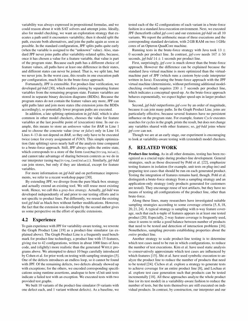
Figure 7: Speed-up of the variability-aware interpreter over
a brute-force approach on 100 small, generated product lines
(break even at the gray line)
intermediate result and store only the single value. Joining canreduce effort in subsequent computations, but executing the joinalso requires computation effort, so there is a trade-off. However, weleave an empirical evaluation of how relevant joins are in practicefor future work.
We have not explored limitations in detail yet. While reflectionseems conceptually possible to support (operating on the variablestructure of the program), I/O poses a problem. If we cannot providea variability-aware test environment, we me might need to performtesting sequentially from the first occurrence of I/O. The WHILE
language does not support I/O; hence, we leave also this problemfor future work.
3.3 Experience
We have implemented a variability-aware interpreter for the WHILE
language, with additional support for procedures. We can parseWHILE programs with preprocessor directives, like those in Fig-ure 4, using the TypeChef variability-aware parser framework [14].We are using this implementation to experiment with different strate-gies (e.g., granularity, different variability representation, when toattempt to join results), and to get a better understanding of whichkinds of product-line implementations can be executed quickly andfor which the execution resembles the brute-force approach (or iseven slower due to the additional SAT solving).
We have developed a generator for random product lines writtenin the WHILE language and have implemented a testing frame-work following the pattern outlined in Figure 1. We generate alldistinct products from our product line and compare the result ofinterpreting them without variability to the result of our variability-aware interpreter. Specifically, we do not generate unit tests, but,in a form of differential testing, we simply compare the stores fol-lowing the equivalence in Figure 1 (4a, 4b). In Figure 7, we showhow the variability-aware interpreter improves performance overthe brute force approach for 100 generated product lines with atmost 6 features (for larger product lines, we were unable to reliablygenerate random products that terminate, we leave this for futurework). Absolute times are within few milliseconds; we gatheredtimes as average from three runs. We can see an overhead for thevariability-aware interpreter, but also that it mostly outperforms thebrute-force analysis as the product-line size increases.
The implementation, which we currently extend with functionsand objects, is available together with the test framework at https://github.com/puschj/Variability-Aware-Interpreter.
1 bool FOO = randomBoolean(), BAR = randomBoolean();
2 int a; bool b;
3 a = 1;
4 if (FOO)
5 b = true;
6 if (a < 3)
7 a = a + 1;
8 if (!FOO)
9 b = false;
10 if (b)
11 a = 0;
12 if (BAR)
13 a = 0;
14 b = (BAR || FOO ? true : false);
15 a = 100 / a;
Figure 8: Code example with variability encoding
4. BLACK BOX: VARIABILITY ENCODING
In addition to implementing a variability-aware interpreter fromscratch, we also experimented with performing variability-awaretesting with existing tools (black-box strategy). We encoded variabil-ity such that we can use an off-the-shelf model checker—JavaPathfinder
(JPF) and its extension jpf-bdd [30] in our case—to run test cases forall configurations. We use the model checker to execute the programpaths of all valid configurations. This corresponds to seperate testingof all configurations in the brute-force approach.
Since model checkers are already capable of dealing with differ-ent values of variables, we encode compile-time variability usingnormal control-flow mechanisms of the host language. For example,we rewrite the code from Figure 4 as shown in Figure 8 (Lines 1–14). We replace preprocessor macros with global Boolean vari-ables (called feature variables; non-deterministically initialized) and#ifdef directives with if statements or conditional expressions. Suchrewrites can be performed mechanically; then, we can proceed withan existing analysis on traditional ASTs without variability. In thegeneral case, the encoding can be trickier, but it is always possibleto encode alternatives by renaming or code replication at statementlevel, as explored elsewhere [2, 13, 27]. Even a variability modelcan be encoded [2, 27]. We call the rewritten product a product-line
simulator (a.k.a. meta-product [27]).After this rewrite, we use JPF to execute test cases. Where the test
case on a single product would run deterministically, we introducenondeterminism through feature variables. Still, JPF explores allfeasible program paths of the simulator and gives warnings if one ofthe paths would result in runtime errors. To illustrate this behavior,we introduced a division-by-zero bug that only occurs when featuresFOO or BAR are selected (Fig. 8, Line 15). The model checker findsthis bug in paths that assign true to FOO or BAR.
Using a model checker for the verification of the simulator is re-warding, because in model checkers “unknown” values for variablesare a common concept and model checkers provide out-of-the-boxsupport. However, by using model checking, we limit the set ofproduct lines that can be verified with the approach. For example,we are not able to verify product lines that contain (potentially)endless loops, need user interaction, or need file or network access.For most of these issues, there is advanced research, but we leavethose for future work.
4.1 Gray-box extensions: jpf-bdd
Using an off-the-shelf model checker, such as JPF, ensures thaterrors in all configurations are found. However, in its standard con-figuration, JPF does not take advantage of the variability informationin the product simulator. In the white-box approach, we knew that
5
variability was always expressed in propositional formulas, and wecould reason about it with SAT solvers and attempt joins. Ideally,also for model checking, we want an exploration strategy that ex-ecutes a path until it encounters variability; then it should split thepath, execute both alternatives, and join the paths again as soon aspossible. In the standard configuration, JPF splits paths quite early(when the variable is assigned to the “unknown” value). Also, stan-dard JPF never joins paths after variability-related splits, because,once it has chosen a value for a feature variable, that value is partof the program state. Because each path has a different choice offeature values, all paths have at least one difference in their states,and different states can never be joined. That is, we split late, butwe never join. In the worst case, this results in one execution pathper configuration, much like in the brute-force approach.
Fortunately, JPF is extensible. For product-line verification, wedeveloped jpf-bdd [30], which enables joining by separating featurevariables from the remaining program state. Feature variables arestored in separate binary decision diagrams (BDDs). Because theprogram states do not contain the feature values any more, JPF cansplit paths later and join more states (the extension joins the BDDsaccordingly), so potentially fewer program paths are executed.
In addition, a late splitting optimization in jpf-bdd, which is alsocommon in other model checkers, chooses the value for featurevariables at the last possible point of (execution) time. In our ex-ample, this means to store an unknown value for BAR in Line 1and to choose the concrete value (true or false) only in Line 14.Lines 4–13 do not depend on BAR, so they only have to be executedtwice (once for every assignment of FOO). This simple optimiza-tion (late splitting) saves nearly half of the analysis time comparedto a brute-force approach. Still, JPF always splits the entire state,which corresponds to a store of the form Cond[Map[String,Value]],and cannot take advantage of sharing between contexts as we do inour interpreter (using Map[String,Cond[Value]]). Similarly, jpf-bdd
can join stores, but only if they are identical, except for featurevariables.
For more information on jpf-bdd and on performance improve-ments, we refer to a recent workshop paper [30].
By extending JPF, we diverge from the pure black-box strategyand actually extend an existing tool. We still reuse most existingwork. Hence, we call this a gray-box strategy. Actually, jpf-bdd wasdeveloped independently of and prior to our testing efforts and isnot specific to product lines. Put differently, we reused the existingtool jpf-bdd as black-box without further modifications. However,the fact that the extension was developed by the second author givesus some perspective on the effort of specific extensions.
4.2 Experience
To gain experience with JPF for variability-aware testing, we rewrotethe Graph Product Line [19] as a product-line simulator (as ex-plained above). The Graph Product Line is a frequently used bench-mark for product-line technology, a product line with 15 features,giving rise to 42 configurations, written in about 1000 lines of Javacode, and (slightly) more realistic than the generated WHILE pro-grams above. We attempted to detect 10 bugs carefully introducedby Cohen et al. for prior work on testing with sampling strategies [5].One of the defects introduces an endless loop, so it cannot be foundwith JPF. Of the remaining defects, two defects already showed upwith exceptions; for the others, we encoded corresponding specifi-cations using runtime assertions, analogue to how xUnit unit testsindicate a failed test with an exception. We executed tests with twoprovided test graphs.
We built 10 variants of the product-line simulator (9 variants withone defect each, and 1 variant without defects). As a baseline, we
tested each of the 42 configurations of each variant in a brute-forcefashion in a standard Java execution environment. Next, we executedJPF (henceforth called jpf-core) and our extension jpf-bdd on all 10variants. We report the arithmetic mean of three executions and thecorresponding standard deviation, with 2 GB RAM on two 1 GHzcores of an Opteron QuadCore machine.
Running tests in the brute-force strategy with Java took 13 ±
0 seconds per product line. In contrast, jpf-core needs 167 ± 50seconds, jpf-bdd 14± 1 seconds per product line.
First, surprisingly, jpf-core is much slower than the brute-forceapproach. However the difference can be explained because thestandard Java virtual machine is more optimized than the virtual-machine part of JPF (which runs a custom byte-code interpreterwritten in Java). Executing the brute-force approach with the JPFvirtual machine (deterministic, without performing additional model-checking overhead) requires 230 ± 7 seconds per product line,which indicates a conceptual speed-up. As the brute-force approachbehaves exponentially, we expect higher speed-ups in larger productlines.
Second, jpf-bdd outperforms jpf-core by an order of magnitude,because it can join many paths. In the Graph Product Line, joins areparticularly effective, because several features have no persistentinfluence on the program state. For example, feature Cycle executessearches for cycles in the graph, prints the result, but does not changeany variables shared with other features; so, jpf-bdd joins wherejpf-core can not.
Though we are at an early stage, our experiment is encouragingto look at variability-aware testing with (extended) model checkers.
5. RELATED WORK
Product-line testing. As in all other domains, testing has been rec-ognized as a crucial topic during product-line development. Generalstrategies, such as those discussed by Pohl et al. [22], emphasizetesting features in isolation (for example, unit tests on plug-ins) andpreparing test cases that should be run on each generated product.Testing the integration of features remains hard, though. Pohl et al.distinguish a brute-force strategy from a sampling strategy and anapplication-only strategy (only products generated for customersare tested). They encourage reuse of test artifacts, but they have nomeans of testing all configurations of the product line, other thanbrute-force.
Along these lines, many researchers have investigated suitablesampling strategies according to some coverage criteria [5, 8, 18,20, 21, 24]. A typical strategy is sampling with n-way feature cover-age, such that each n-tuple of features appears in at least one testedproduct [20]. Especially, 2-way feature coverage is frequently used,since it seems to strike a good balance between number of productsthat need to be tested and detection of interaction problems [16].Nonetheless, sampling prevents establishing properties about theentire product line.
Another strategy to scale product-line testing is to determinewhich test cases need to be run in which configurations, to reducethe number of test executions. Kim et al. have used static analysisto conservatively approximate which test cases are influenced bywhich features [15]. Shi et al. have used symbolic execution to an-alyze the product line to reduce the number of products that needto be tested [24]. Cichos et al. explore a strategy to generate teststo achieve coverage for an entire product line [8], and Lochau etal. explore test case generation such that products can be testedincrementally [18]. All these approaches analyze the whole productline (or its test model) in a variability-aware fashion to reduce thenumber of tests, but the tests themselves are still executed on indi-vidual products. In contrast, by construction, our interpreter and our
6
encoding with model checking cover the entire product line and splittest execution only when needed, without dedicated prior analysis.
Variability-aware analysis. Although a rather recent researchtopic, many researchers have investigated strategies for variability-aware analysis for parsing (white-box [14]), type checking (white-box [1,7,13,25] and black-box [23]), model checking (white-box [9,17] and black-box [2, 23]), static analysis (white-box [4] and black-box [3]), and theorem proving (black-box [27]). For a detailedoverview of that field, we defer the interested reader to a recentsurvey [26].
The specific style of writing a variability-aware analysis by map-ping over conditional data structures was inspired by variational
programming by Erwig and Walkingshaw [11, 12]. They also pre-sented and formalized a type system for the lambda calculus in thisstyle [7]. Our encoding differs from theirs in that we encode choicesand feature models with arbitrary propositional formulas, insteadof using atomic feature names defined within the conditional datastructure. This difference makes our approach potentially simplerand more flexible, but also more expensive to compute (we rely onSAT solvers or BDDs).
Our interpreter implements a form of mixed concrete/symbolicexecution—see [6] for an overview of that field. Conceptually, in thevariability-encoded version, we consider all feature variables as sym-bolic and execute the remaining program with concrete values. Wehave not yet experimented with existing tools for symbolic execution.They seem promising as black-box tools for the variability-encodingstrategy. There is a rich and advanced collection of tools to explorefor product-line testing in future work.
6. DISCUSSION AND CONCLUSIONS
We have investigated variability-aware testing with a white-box strat-egy (variability-aware interpreter), a black-box strategy (variabilityencoding for JPF), and even a gray-box strategy (variability encod-ing for jpf-bdd). In all cases, we run a test case on all configurationsof a product line at once, as opposed to a brute-force or samplingstrategy. Although it is too early to draw sound conclusions, we wantto share our observations and encourage feedback at this early stage.We have gained interesting insights into the spectrum between white-box, gray-box, and black-box analyses regarding implementationeffort and flexibility.
Effort. The white-box strategy obviously requires more effort toimplement than the black-box strategy. We need to write our own in-terpreter from scratch or significantly rewrite an existing interpreter,because variability pervades all data structures and execution steps.While writing interpreters is well understood, writing an interpreterfor a full language such as Java, C, or JavaScript requires significanteffort. In contrast, reusing existing and optimized tools in the black-box strategy allowed us to experiment directly with Java code withmuch less effort.
Flexibility. The white-box strategy is more flexible than the black-box strategy. The black-box strategy depends very much on thepower of the existing analysis and how efficiently it deals withvariability. We have to ‘hope’ that their optimizations fit to ouruse cases (test case execution despite variability in our case). Thevariability encoding does not necessarily have the shape of typicalprograms for which general-purpose analysis may be optimized.
Product-line analysis is special in that variability follows only fewrestricted patterns, reducible to propositional formulas and Booleansatisfiability problems. Those specifics are usually not consideredby the black-box tools or might even get lost in the encoding (i.e.,analyzing arbitrary expressions in if statements is much harder thananalyzing presence conditions in choice nodes). By extending exist-ing tools (gray-box strategy; jpf-bdd in our case), we can attempt to
1 int a, c, res;
2 #ifdef FOO
3 a = 3;
4 #else5 a = 2;
6 #endif7 c = 1;
8 res = 1;
9 while (c < a) {
10 c = c + 1;
11 res = res * c;
12 }
13 assert(res < 10);
a=Choice(FOO, 3, 2)c=1
res=1
true: a=…; c=1; res=1
true: while (c<a)
a=Choice(FOO, 3, 2)c=2
res=2
true: c=c+1; res=res*c
true: while (c<a)
a=Choice(FOO, 3, 2)c=Choice(FOO, 3, 2)res=Choice(FOO, 6, 2)
FOO: c=c+1; res=res*c
FOO: while (c<a)
false: c=c+1; res=res*c
true: assert...
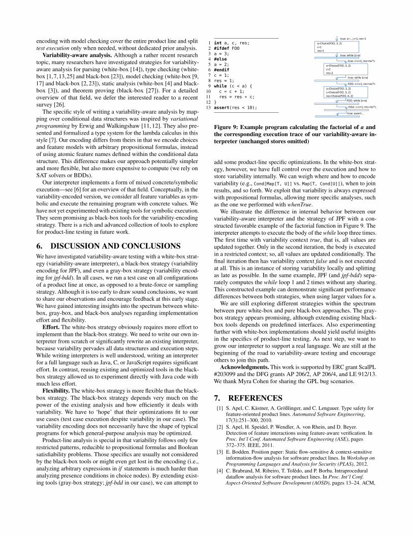
Figure 9: Example program calculating the factorial of a and
the corresponding execution trace of our variability-aware in-
terpreter (unchanged stores omitted)
add some product-line specific optimizations. In the white-box strat-egy, however, we have full control over the execution and how tostore variability internally. We can weigh where and how to encodevariability (e.g., Cond[Map[T, U]] vs. Map[T, Cond[U]]), when to joinresults, and so forth. We exploit that variability is always expressedwith propositional formulas, allowing more specific analyses, suchas the one we performed with whenTrue.
We illustrate the difference in internal behavior between ourvariability-aware interpreter and the strategy of JPF with a con-structed favorable example of the factorial function in Figure 9. Theinterpreter attempts to execute the body of the while loop three times.The first time with variability context true, that is, all values areupdated together. Only in the second iteration, the body is executedin a restricted context; so, all values are updated conditionally. Thefinal iteration then has variability context false and is not executedat all. This is an instance of storing variability locally and splittingas late as possible. In the same example, JPF (and jpf-bdd) sepa-rately computes the while loop 1 and 2 times without any sharing.This constructed example can demonstrate significant performancedifferences between both strategies, when using larger values for a.
We are still exploring different strategies within the spectrumbetween pure white-box and pure black-box approaches. The gray-box strategy appears promising, although extending existing black-box tools depends on predefined interfaces. Also experimentingfurther with white-box implementations should yield useful insightsin the specifics of product-line testing. As next step, we want togrow our interpreter to support a real language. We are still at thebeginning of the road to variability-aware testing and encourageothers to join this path.
Acknowledgments. This work is supported by ERC grant ScalPL#203099 and the DFG grants AP 206/2, AP 206/4, and LE 912/13.We thank Myra Cohen for sharing the GPL bug scenarios.
7. REFERENCES
[1] S. Apel, C. Kästner, A. Größlinger, and C. Lengauer. Type safety forfeature-oriented product lines. Automated Software Engineering,17(3):251–300, 2010.
[2] S. Apel, H. Speidel, P. Wendler, A. von Rhein, and D. Beyer.Detection of feature interactions using feature-aware verification. InProc. Int’l Conf. Automated Software Engineering (ASE), pages372–375. IEEE, 2011.
[3] E. Bodden. Position paper: Static flow-sensitive & context-sensitiveinformation-flow analysis for software product lines. In Workshop on
Programming Languages and Analysis for Security (PLAS), 2012.
[4] C. Brabrand, M. Ribeiro, T. Tolêdo, and P. Borba. Intraproceduraldataflow analysis for software product lines. In Proc. Int’l Conf.
Aspect-Oriented Software Development (AOSD), pages 13–24. ACM,
7
2012.
[5] I. Cabral, M. B. Cohen, and G. Rothermel. Improving the testing andtestability of software product lines. In Proc. Int’l Software Product
Line Conference (SPLC), volume 6287 of LNCS, pages 241–255.Springer, 2010.
[6] C. Cadar, P. Godefroid, S. Khurshid, C. S. Pasareanu, K. Sen,N. Tillmann, and W. Visser. Symbolic execution for software testing inpractice: Preliminary assessment. In Proc. Int’l Conf. Software
Engineering (ICSE), pages 1066–1071. ACM, 2011.
[7] S. Chen, M. Erwig, , and E. Walkingshaw. Extending type inference tovariational programs. Technical report (draft), School of EECS,Oregon State University, 2012.
[8] H. Cichos, S. Oster, M. Lochau, and A. Schürr. Model-basedcoverage-driven test suite generation for software product lines. InProc. Int’l Conf. Model Driven Engineering Languages and Systems
(MoDELS), volume 6981 of LNCS, pages 425–439. Springer, 2011.
[9] A. Classen, P. Heymans, P.-Y. Schobbens, A. Legay, and J.-F. Raskin.Model checking lots of systems: Efficient verification of temporalproperties in software product lines. In Proc. Int’l Conf. Software
Engineering (ICSE), pages 335–344. ACM, 2010.
[10] K. Czarnecki and U. Eisenecker. Generative Programming: Methods,
Tools, and Applications. ACM Press/Addison-Wesley, New York,2000.
[11] M. Erwig and E. Walkingshaw. The choice calculus: A representationfor software variation. ACM Trans. Softw. Eng. Methodol. (TOSEM),21(1):Article 6, 2011.
[12] M. Erwig and E. Walkingshaw. Variation programming with thechoice calculus. In Proc. Int’l Summer School on Generative and
Transformational Techniques in Software Engineering (GTTSE), 2011.
[13] C. Kästner, S. Apel, T. Thüm, and G. Saake. Type checkingannotation-based product lines. ACM Trans. Softw. Eng. Methodol.
(TOSEM), 21(3), 2012.
[14] C. Kästner, P. G. Giarrusso, T. Rendel, S. Erdweg, K. Ostermann, andT. Berger. Variability-aware parsing in the presence of lexical macrosand conditional compilation. In Proc. Int’l Conf. Object-Oriented
Programming, Systems, Languages and Applications (OOPSLA),pages 805–824. ACM, 2011.
[15] C. H. P. Kim, D. S. Batory, and S. Khurshid. Reducing combinatoricsin testing product lines. In Proc. Int’l Conf. Aspect-Oriented Software
Development (AOSD), pages 57–68. ACM, 2011.
[16] D. R. Kuhn, D. R. Wallace, and A. M. Gallo. Software faultinteractions and implications for software testing. IEEE Trans. Softw.
Eng. (TSE), 30:418–421, 2004.
[17] K. Lauenroth, K. Pohl, and S. Toehning. Model checking of domainartifacts in product line engineering. In Proc. Int’l Conf. Automated
Software Engineering (ASE), pages 269–280. IEEE, 2009.
[18] M. Lochau, I. Schaefer, J. Kamischke, and S. Lity. Incrementalmodel-based testing of delta-oriented software product lines. In Proc.
Int’l Conf. Tests and Proofs (TAP), volume 7305 of LNCS, pages67–82. Springer, 2012.
[19] R. Lopez-Herrejon and D. Batory. A standard problem for evaluatingproduct-line methodologies. In Proc. Int’l Conf. Generative and
Component-Based Software Engineering (GCSE), volume 2186 ofLNCS, pages 10–24. Springer, 2001.
[20] S. Oster, F. Markert, and P. Ritter. Automated incremental pairwisetesting of software product lines. In Proc. Int’l Software Product Line
Conference (SPLC), volume 6287 of LNCS, pages 196–210. Springer,2010.
[21] G. Perrouin, S. Sen, J. Klein, B. Baudry, and Y. le Traon. Automatedand scalable t-wise test case generation strategies for software productlines. In Proc. Int’l Conf. Software Testing, Verification, and
Validation, pages 459–468. IEEE, 2010.
[22] K. Pohl, G. Böckle, and F. J. van der Linden. Software Product Line
Engineering: Foundations, Principles and Techniques. Springer,Berlin/Heidelberg, 2005.
[23] H. Post and C. Sinz. Configuration lifting: Verification meets softwareconfiguration. In Proc. Int’l Conf. Automated Software Engineering
(ASE), pages 347–350. IEEE, 2008.
[24] J. Shi, M. Cohen, and M. Dwyer. Integration testing of softwareproduct lines using compositional symbolic execution. In Proc. Int’l
Conf. Fundamental Approaches to Software Engineering, volume
7212 of LNCS, pages 270–284. Springer, 2012.
[25] S. Thaker, D. Batory, D. Kitchin, and W. Cook. Safe composition ofproduct lines. In Proc. Int’l Conf. Generative Programming and
Component Engineering (GPCE), pages 95–104. ACM, 2007.
[26] T. Thüm, S. Apel, C. Kästner, M. Kuhlemann, I. Schaefer, andG. Saake. Analysis strategies for software product lines. TechnicalReport FIN-004-2012, School of Computer Science, University ofMagdeburg, 2012.
[27] T. Thüm, I. Schaefer, S. Apel, and M. Hentschel. Family-baseddeductive verification of software product lines. In Proc. Int’l Conf.
Generative Programming and Component Engineering (GPCE).ACM, 2012.
[28] E. Uzuncaova, D. Garcia, S. Khurshid, and D. Batory. Aspecification-based approach to testing software product lines. In Proc.
Europ. Software Engineering Conf./Foundations of Software
Engineering (ESEC/FSE), pages 525–528. ACM, 2007.
[29] W. Visser, K. Havelund, G. P. Brat, S. Park, and F. Lerda. Modelchecking programs. Autom. Softw. Eng., 10(2):203–232, 2003.
[30] A. von Rhein, S. Apel, and F. Raimondi. Introducing binary decisiondiagrams in the explicit-state verification of Java code. In Proc. Java
Pathfinder Workshop, 2011.
8
Conditioned Model Slicing of Feature-AnnotatedState Machines
Jochen KamischkeInstitut für Programmierung
und Reaktive SystemeMühlenpfordtstr. 23
Braunschweig, [email protected]
Malte LochauInstitut für Programmierung
und Reaktive SystemeMühlenpfordtstr. 23
Braunschweig, [email protected]
Hauke BallerInstitut für Programmierung
und Reaktive SystemeMühlenpfordtstr. 23
Braunschweig, [email protected]
ABSTRACTModel-based behavioral specifications build the basis forcomprehensive quality assurance techniques for complexsoftware systems such as model checking and model-basedtesting. Various attempts exist to adopt those approachesto variant-rich applications as apparent in software productline engineering to efficiently analyze families of similar soft-ware systems. Therefore, models are usually enriched withcapabilities to explicitly specify variable parts by means ofannotations denoting selection conditions over feature pa-rameters. However, a major drawback of model-based en-gineering is still its lack of scalability. Model slicing pro-vides a promising technique to reduce models to only thoseobjects being relevant for a certain criterion under consid-eration such as a particular test goal. Here, we present anapproach for slicing feature-annotated state machine mod-els. To support feature-oriented slicing on those models,our framework combines principles of variability encodingand conditioned slicing. We also present an implementationand provide experimental results concerning the efficiencyof the slicing algorithm.
Categories and Subject DescriptorsD.2.4 [Software Engineering]: Software/Program Veri-fication; D.2.13 [Software Engineering]: Reusable Soft-ware, Reuse Models
General TermsDesign, Theory
KeywordsSoftware Product Lines, Model-Based Software Engineering.
1. INTRODUCTIONModel-based software engineering provides a rich collec-
tion of modeling languages and corresponding techniques for
Permission to make digital or hard copies of all or part of this work forpersonal or classroom use is granted without fee provided that copies arenot made or distributed for profit or commercial advantage and that copiesbear this notice and the full citation on the first page. To copy otherwise, torepublish, to post on servers or to redistribute to lists, requires prior specificpermission and/or a fee.FOSD’12, September 24–25, 2012, Dresden, Germany.Copyright 2012 ACM 978-1-4503-1309-4/12/09 ...$10.00.
the specification, documentation, maintenance, and verifi-cation/validation of high-quality software systems in a sys-tematic way. In particular, modeling approaches for specify-ing the operational behavior of a software system are oftenbased on state-transition diagrams such as UML state ma-chines [18]. Thereupon, various applications of those modelsto verification/validation techniques like model-based test-ing and model checking have been proposed [5, 1].
However, the major drawback of those approaches is stilltheir lack of scalability. This is even worse in the presenceof explicit variability at model level as apparent, e.g., insoftware product line engineering [15]. Herein, models areenriched with capabilities to specify common and variableparts occurring in a family of similar product variants. Forinstance, model elements are annotated with selection con-ditions, i.e., propositional formulas over feature parametersto guide the assembling of model variants w.r.t. a particu-lar feature configuration [5]. Hence, such feature-annotatedmodels integrate any potential behaviors of all product vari-ants of an SPL within a virtual, so-called 150% model. Thisadditional model dimension as tailored by the valid prod-uct configuration space of an underlying domain featuremodel [11] further complicates the application of model-based analysis techniques to variant-rich, real world prob-lems represented by an SPL.
Model slicing provides a promising approach to handlethe complexity problem of behavioral models by perform-ing static, i.e., syntactical model reductions that preservesome aspects of model semantics w.r.t. a slicing criterion un-der consideration [22, 21]. Therefore, model slicing extractsthose model parts affecting certain computational units onlyand, at the same time, ensuring the resulting model slice topreserve a syntactically well-formed model structure. Slicinghas gained applications in various fields of program analysisfor reverse engineering, program integration, software met-rics, component reuse, etc. [3]. Model slicing adopts theconcepts of program slicing to reduce verification/validationefforts. For instance, in model-based testing, choosing testgoals as slicing criteria allows for efficient test case genera-tion, debugging, and change impact analysis during regres-sion testing, whereas slicing along a certain model property,e.g., given as an LTL formula, decreases model checkingcomplexity. However, recent model slicing approaches areincapable to cope with models enriched with feature anno-tations. In the presence of variable model parts, the furthermodel dimension has to be taken into account when slic-ing for a particular criterion in order to yield a well-formed
9
model for every model variant that contains all parts rele-vant for the criterion.
In this paper, we present a framework that enhancesmodel slicing to state machine models with explicit vari-ability in terms of feature annotations. Besides well-knownslicing-based model analysis techniques, we use conditionedslicing [19] to enrich slicing criteria with constraints overfeature values thus constituting a (partial) product config-uration the slice is to be derived from. Therefore, we usevariability encoding [5] to embed feature annotations intomodels such that slicing algorithms are able to treat themas regular computational units. This allows the analysisof behavioral commonality and variability among productvariants, e.g., for efficient verification of complete productfamilies [4, 1], feature interaction detection [20, 12] and in-cremental SPL testing [13]. The concepts are illustrated bya running example based on the Vending Machine SPL [4, 8]and evaluated by means of a case study from the automotivedomain [14]. We also present a sample implementation andevaluation results for our approach.
The paper is organized as follows. In Sect. 2, we reviewbasic notions of state machines and how to enrich them withexplicit feature annotations to model variable behavior inthe SPL context. In Sect. 3, we outline a model slicing al-gorithm for state machines and extend it to be applicableto feature-annotated state machines. In Sect. 4, we presentan implementation based on variability encoding and con-ditioned slicing and show results of some experiments per-formed. Sect. 5 concludes.
2. STATE MACHINE MODELS WITHFEATURE ANNOTATIONS
We first review the common modeling concepts of statemachines. For a detailed survey of the abstract syntax andformal semantics of various state machine variants, we refer,e.g., to [7]. We then describe extensions to model behav-ioral variability among different SPL product variants us-ing feature-annotated state machines with explicit selectionconditions over feature parameters organized in a domainfeature model.
2.1 State Machine ModelsState machines provide behavioral specifications of (soft-
ware) systems by means of computational states s ∈ S andtransitions t = (s, l, s′) ∈ T leading from a source state s ∈ Sto a target state s′ ∈ S, where label l denotes (re-)actionsof the system. Originating from Harel’s Statecharts [10],various variants and implementations of state-machine-likemodeling approaches appeared, e.g., UML state machines[18] and Matlab/Simulink/Stateflow [6].
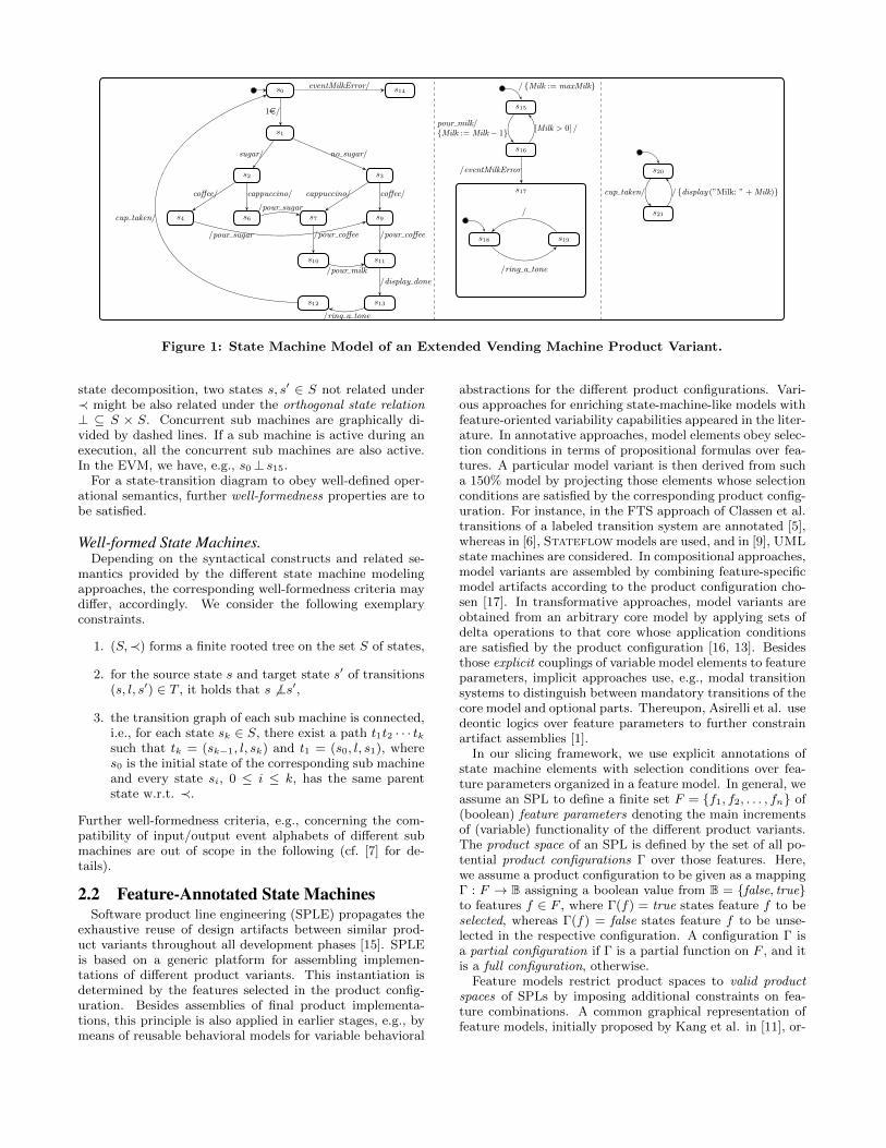
State machines are represented as state-transition graphsenriched with several extensions for modeling complex sys-tem behavior. Vertices are visualized as rectangles withcurved edges and denote states. Transitions between statesare visualized as directed, labeled edges. A sample statemachine model for the control logics of the Extended Vend-ing Machine (EVM) SPL case study is depicted in Fig. 1.The Vending Machine SPL originates from a case study pre-sented in [4, 8]. The state machine is divided into threeconcurrent parts. The left part is the vending machine itselfwith functionality for producing sugared and non-sugaredcoffee and cappuccino. In the middle, we extend the origi-
nal machine by a milk administration system, that tracks themilk usage an produces a warning if a predefined amount ofmilk is consumed. The right part gives an advise to admin-istration staff to refill milk. The control cycle of the vendingmachine lets the user first insert money and then to choosewhether he/she prefers sugared or non-sugared beverage. Inthe second step, the user has to choose the desired bever-age which is then produced. When finished, a ring tone isplayed.
Labels l of transitions t = (s, l, s′) specify the visible,event-based behavior of the system. We sometimes write
sl−→ s′ for short, where l might be omitted if not relevant.
Labels consist of two parts, a trigger and an action. Thetransition trigger denotes an input event ei to occur for re-leasing the transition, whereas the transition action denotesan output event eo emitted as system reaction to this input.The set of behaviors specified by a state machine is givenas the set of, potentially infinite, sequences of action/reac-tion pairs that correspond to valid paths, i.e., a consecutivesequence of transitions in the state-transition graph start-ing from a well-defined initial state s0. In Fig. 1 a samplesequence of action/reaction pairs is
(1 e, ), (no sugar, ), (coffee, ), ( , pour coffee),
( , display done), ( , ring a tone), (cup taken, )
where the corresponding valid path is
s01e/−−→ s1
no sugar/−−−−−−→ s3coffee/−−−−→ s9
/pour coffee−−−−−−−→ s11/display done−−−−−−−−→ s13
/ring a tone−−−−−−−→ s12cup taken/−−−−−−→ s0
A transition with an empty trigger part is always enabledwhenever its source state is active. Branches in the state-transition graph specify alternative behavior, e.g., the choicebetween sugar and no sugar in state s1 yields two differ-ent subsequent paths. Loops specify reactive behavior, e.g.,the EVM returns to the initial state s0 after a service iscompleted. State machine labels are often further extendedto complex transition labels, e.g., incorporating conditionalguarding expressions G in addition to the triggering eventand computational statements in the action part, both ac-cessing and/or changing values of internal variables v tospecify internal data flows. In the EVM example, an in-teger variable Milk is used to store the current amount ofmilk. We use the following notation for transitions labels
ei [ G ] / {act}; eowhere computational actions in the {act} component aregiven as assignment statements on internal variables in ourexample. Again, all label components are optional. Com-plex transition labels cause computational states of a statemachine under execution to be further enriched by internalstatus information, e.g., comprising variable values.
Considering the state structure, recent state machinemodeling approaches provide hierarchical, as well as parallelde-composition of states by means of nested sub machines.Hierarchical state decomposition defines a sub state relation≺⊆ S × S thus for nesting state machines into states. Thestate s17 in our example is extended by adding two sub statess18 and s19. If s17 is entered, s18 is simultaneous entered asit is marked as initial state of this sub machine. Two statess, s′ ∈ S not being related under ≺ are excluding each other,denoted by a state exclusion relation # ⊆ S× S (for exam-ple states s16 and s18). In state machines with concurrent
10
s0
s1
s6s4 s7 s9
s2 s3
s10 s11
s12 s13
1e/
sugar/ no sugar/
coffee/ coffee/cappuccino/ cappuccino/
/pour sugar
/pour sugar /pour coffee /pour coffee
/pour milk
/display done
/ring a tone
cup taken/
s14eventMilkError/
s15
s16
s17
s18 s19
/ring a tone
/
/ {Milk := maxMilk}
pour milk/{Milk := Milk− 1} [Milk > 0] /
/eventMilkError s20
s21
cup taken/ / {display (”Milk: ” + Milk)}
Figure 1: State Machine Model of an Extended Vending Machine Product Variant.
state decomposition, two states s, s′ ∈ S not related under≺ might be also related under the orthogonal state relation⊥ ⊆ S × S. Concurrent sub machines are graphically di-vided by dashed lines. If a sub machine is active during anexecution, all the concurrent sub machines are also active.In the EVM, we have, e.g., s0⊥ s15.
For a state-transition diagram to obey well-defined oper-ational semantics, further well-formedness properties are tobe satisfied.
Well-formed State Machines.Depending on the syntactical constructs and related se-
mantics provided by the different state machine modelingapproaches, the corresponding well-formedness criteria maydiffer, accordingly. We consider the following exemplaryconstraints.
1. (S,≺) forms a finite rooted tree on the set S of states,
2. for the source state s and target state s′ of transitions(s, l, s′) ∈ T , it holds that s 6⊥s′,
3. the transition graph of each sub machine is connected,i.e., for each state sk ∈ S, there exist a path t1t2 · · · tksuch that tk = (sk−1, l, sk) and t1 = (s0, l, s1), wheres0 is the initial state of the corresponding sub machineand every state si, 0 ≤ i ≤ k, has the same parentstate w.r.t. ≺.
Further well-formedness criteria, e.g., concerning the com-patibility of input/output event alphabets of different submachines are out of scope in the following (cf. [7] for de-tails).
2.2 Feature-Annotated State MachinesSoftware product line engineering (SPLE) propagates the
exhaustive reuse of design artifacts between similar prod-uct variants throughout all development phases [15]. SPLEis based on a generic platform for assembling implemen-tations of different product variants. This instantiation isdetermined by the features selected in the product config-uration. Besides assemblies of final product implementa-tions, this principle is also applied in earlier stages, e.g., bymeans of reusable behavioral models for variable behavioral
abstractions for the different product configurations. Vari-ous approaches for enriching state-machine-like models withfeature-oriented variability capabilities appeared in the liter-ature. In annotative approaches, model elements obey selec-tion conditions in terms of propositional formulas over fea-tures. A particular model variant is then derived from sucha 150% model by projecting those elements whose selectionconditions are satisfied by the corresponding product config-uration. For instance, in the FTS approach of Classen et al.transitions of a labeled transition system are annotated [5],whereas in [6], Stateflow models are used, and in [9], UMLstate machines are considered. In compositional approaches,model variants are assembled by combining feature-specificmodel artifacts according to the product configuration cho-sen [17]. In transformative approaches, model variants areobtained from an arbitrary core model by applying sets ofdelta operations to that core whose application conditionsare satisfied by the product configuration [16, 13]. Besidesthose explicit couplings of variable model elements to featureparameters, implicit approaches use, e.g., modal transitionsystems to distinguish between mandatory transitions of thecore model and optional parts. Thereupon, Asirelli et al. usedeontic logics over feature parameters to further constrainartifact assemblies [1].
In our slicing framework, we use explicit annotations ofstate machine elements with selection conditions over fea-ture parameters organized in a feature model. In general, weassume an SPL to define a finite set F = {f1, f2, . . . , fn} of(boolean) feature parameters denoting the main incrementsof (variable) functionality of the different product variants.The product space of an SPL is defined by the set of all po-tential product configurations Γ over those features. Here,we assume a product configuration to be given as a mappingΓ : F → B assigning a boolean value from B = {false, true}to features f ∈ F , where Γ(f) = true states feature f to beselected, whereas Γ(f) = false states feature f to be unse-lected in the respective configuration. A configuration Γ isa partial configuration if Γ is a partial function on F , and itis a full configuration, otherwise.
Feature models restrict product spaces to valid productspaces of SPLs by imposing additional constraints on fea-ture combinations. A common graphical representation offeature models, initially proposed by Kang et al. in [11], or-
11
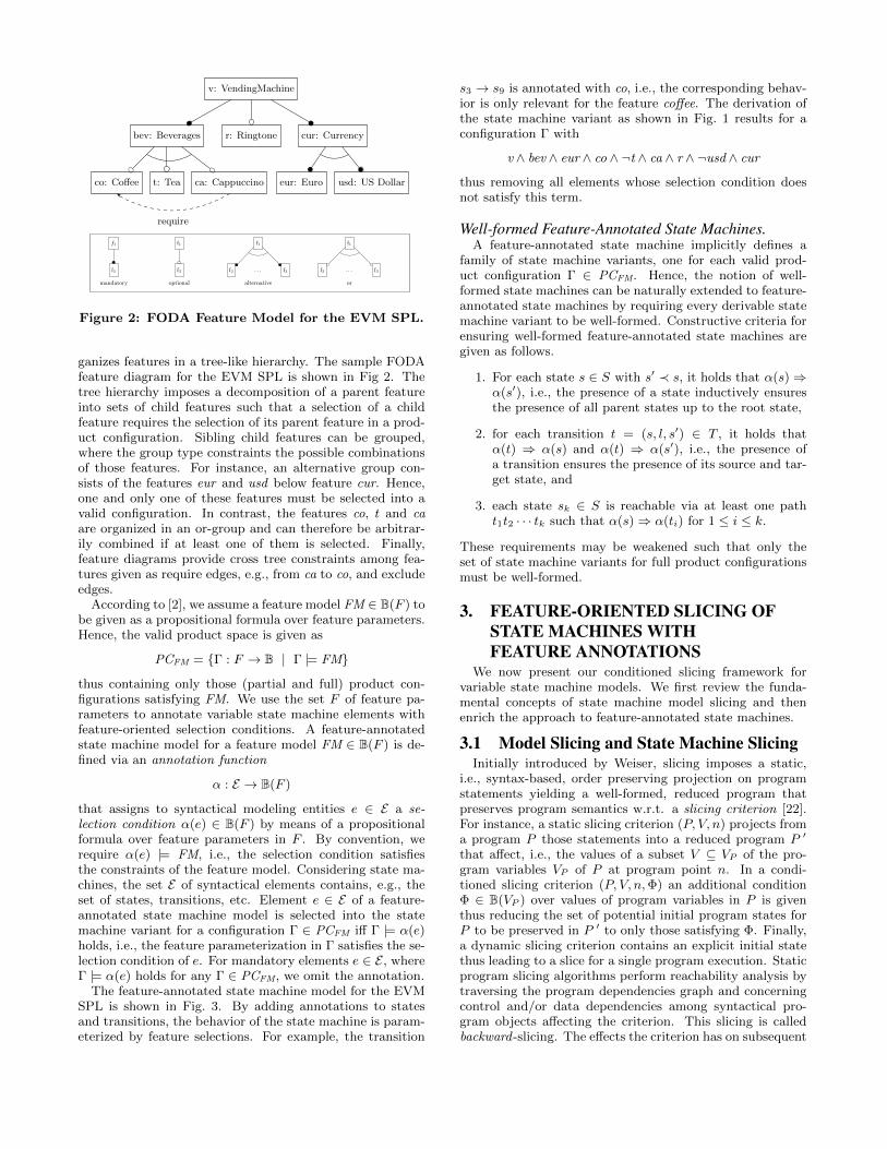
v: VendingMachine
bev: Beverages
co: Coffee t: Tea ca: Cappuccino
r: Ringtone cur: Currency
eur: Euro usd: US Dollar
require
f1
f2
mandatory
f1
f2
optional
f1
f2 . . .
alternative
f3
f1
f2 . . .
or
f3
Figure 2: FODA Feature Model for the EVM SPL.
ganizes features in a tree-like hierarchy. The sample FODAfeature diagram for the EVM SPL is shown in Fig 2. Thetree hierarchy imposes a decomposition of a parent featureinto sets of child features such that a selection of a childfeature requires the selection of its parent feature in a prod-uct configuration. Sibling child features can be grouped,where the group type constraints the possible combinationsof those features. For instance, an alternative group con-sists of the features eur and usd below feature cur. Hence,one and only one of these features must be selected into avalid configuration. In contrast, the features co, t and caare organized in an or-group and can therefore be arbitrar-ily combined if at least one of them is selected. Finally,feature diagrams provide cross tree constraints among fea-tures given as require edges, e.g., from ca to co, and excludeedges.
According to [2], we assume a feature model FM ∈ B(F ) tobe given as a propositional formula over feature parameters.Hence, the valid product space is given as
PCFM = {Γ : F → B | Γ |= FM}
thus containing only those (partial and full) product con-figurations satisfying FM. We use the set F of feature pa-rameters to annotate variable state machine elements withfeature-oriented selection conditions. A feature-annotatedstate machine model for a feature model FM ∈ B(F ) is de-fined via an annotation function
α : E → B(F )
that assigns to syntactical modeling entities e ∈ E a se-lection condition α(e) ∈ B(F ) by means of a propositionalformula over feature parameters in F . By convention, werequire α(e) |= FM, i.e., the selection condition satisfiesthe constraints of the feature model. Considering state ma-chines, the set E of syntactical elements contains, e.g., theset of states, transitions, etc. Element e ∈ E of a feature-annotated state machine model is selected into the statemachine variant for a configuration Γ ∈ PCFM iff Γ |= α(e)holds, i.e., the feature parameterization in Γ satisfies the se-lection condition of e. For mandatory elements e ∈ E , whereΓ |= α(e) holds for any Γ ∈ PCFM, we omit the annotation.
The feature-annotated state machine model for the EVMSPL is shown in Fig. 3. By adding annotations to statesand transitions, the behavior of the state machine is param-eterized by feature selections. For example, the transition
s3 → s9 is annotated with co, i.e., the corresponding behav-ior is only relevant for the feature coffee. The derivation ofthe state machine variant as shown in Fig. 1 results for aconfiguration Γ with
v ∧ bev ∧ eur ∧ co ∧ ¬t ∧ ca ∧ r ∧ ¬usd ∧ cur
thus removing all elements whose selection condition doesnot satisfy this term.
Well-formed Feature-Annotated State Machines.A feature-annotated state machine implicitly defines a
family of state machine variants, one for each valid prod-uct configuration Γ ∈ PCFM. Hence, the notion of well-formed state machines can be naturally extended to feature-annotated state machines by requiring every derivable statemachine variant to be well-formed. Constructive criteria forensuring well-formed feature-annotated state machines aregiven as follows.
1. For each state s ∈ S with s′ ≺ s, it holds that α(s)⇒α(s′), i.e., the presence of a state inductively ensuresthe presence of all parent states up to the root state,
2. for each transition t = (s, l, s′) ∈ T , it holds thatα(t) ⇒ α(s) and α(t) ⇒ α(s′), i.e., the presence ofa transition ensures the presence of its source and tar-get state, and
3. each state sk ∈ S is reachable via at least one patht1t2 · · · tk such that α(s)⇒ α(ti) for 1 ≤ i ≤ k.
These requirements may be weakened such that only theset of state machine variants for full product configurationsmust be well-formed.
3. FEATURE-ORIENTED SLICING OFSTATE MACHINES WITHFEATURE ANNOTATIONS
We now present our conditioned slicing framework forvariable state machine models. We first review the funda-mental concepts of state machine model slicing and thenenrich the approach to feature-annotated state machines.
3.1 Model Slicing and State Machine SlicingInitially introduced by Weiser, slicing imposes a static,
i.e., syntax-based, order preserving projection on programstatements yielding a well-formed, reduced program thatpreserves program semantics w.r.t. a slicing criterion [22].For instance, a static slicing criterion (P, V, n) projects froma program P those statements into a reduced program P ′
that affect, i.e., the values of a subset V ⊆ VP of the pro-gram variables VP of P at program point n. In a condi-tioned slicing criterion (P, V, n,Φ) an additional conditionΦ ∈ B(VP ) over values of program variables in P is giventhus reducing the set of potential initial program states forP to be preserved in P ′ to only those satisfying Φ. Finally,a dynamic slicing criterion contains an explicit initial statethus leading to a slice for a single program execution. Staticprogram slicing algorithms perform reachability analysis bytraversing the program dependencies graph and concerningcontrol and/or data dependencies among syntactical pro-gram objects affecting the criterion. This slicing is calledbackward-slicing. The effects the criterion has on subsequent
12
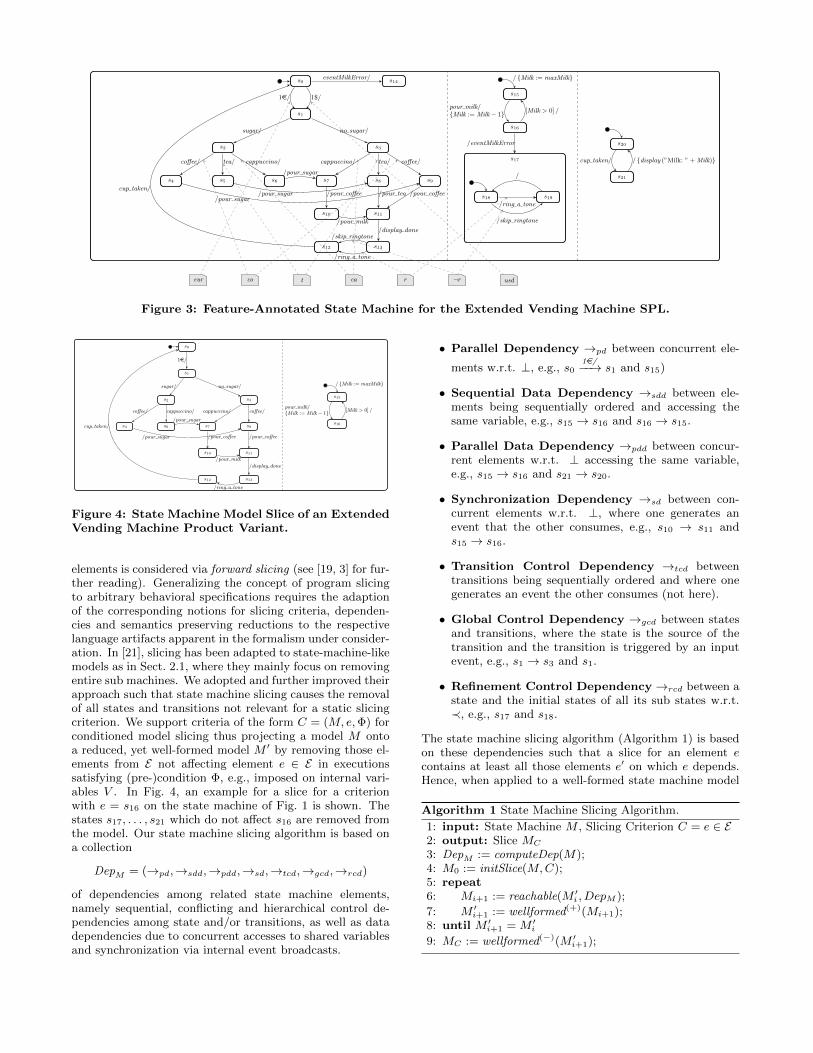
s0
s1
s6s5s4 s7 s8 s9
s2 s3
s10 s11
s12 s13
1e/ 1$/
sugar/ no sugar/
coffee/ coffee/tea/ tea/cappuccino/ cappuccino/
/pour sugar
/pour sugar/pour sugar
/pour coffee /pour tea /pour coffee
/pour milk
/display done/skip ringtone
/ring a tone
cup taken/
s14eventMilkError/
s15
s16
s17
s18 s19
/skip ringtone
/ring a tone
/
/ {Milk := maxMilk}
pour milk/{Milk := Milk− 1} [Milk > 0] /
/eventMilkError s20
s21
cup taken/ / {display (”Milk: ” + Milk)}
r ¬rcatcoeur usd
Figure 3: Feature-Annotated State Machine for the Extended Vending Machine SPL.
s0
s1
s6s4 s7 s9
s2 s3
s10 s11
s12 s13
1e/
sugar/ no sugar/
coffee/ coffee/cappuccino/ cappuccino/
/pour sugar
/pour sugar /pour coffee /pour coffee
/pour milk
/display done
/ring a tone
cup taken/
s15
s16
/ {Milk := maxMilk}
pour milk/{Milk := Milk− 1} [Milk > 0] /
Figure 4: State Machine Model Slice of an ExtendedVending Machine Product Variant.
elements is considered via forward slicing (see [19, 3] for fur-ther reading). Generalizing the concept of program slicingto arbitrary behavioral specifications requires the adaptionof the corresponding notions for slicing criteria, dependen-cies and semantics preserving reductions to the respectivelanguage artifacts apparent in the formalism under consider-ation. In [21], slicing has been adapted to state-machine-likemodels as in Sect. 2.1, where they mainly focus on removingentire sub machines. We adopted and further improved theirapproach such that state machine slicing causes the removalof all states and transitions not relevant for a static slicingcriterion. We support criteria of the form C = (M, e,Φ) forconditioned model slicing thus projecting a model M ontoa reduced, yet well-formed model M ′ by removing those el-ements from E not affecting element e ∈ E in executionssatisfying (pre-)condition Φ, e.g., imposed on internal vari-ables V . In Fig. 4, an example for a slice for a criterionwith e = s16 on the state machine of Fig. 1 is shown. Thestates s17, . . . , s21 which do not affect s16 are removed fromthe model. Our state machine slicing algorithm is based ona collection
DepM = (→pd,→sdd,→pdd,→sd,→tcd,→gcd,→rcd)
of dependencies among related state machine elements,namely sequential, conflicting and hierarchical control de-pendencies among state and/or transitions, as well as datadependencies due to concurrent accesses to shared variablesand synchronization via internal event broadcasts.
• Parallel Dependency →pd between concurrent ele-
ments w.r.t. ⊥, e.g., s01e/−−→ s1 and s15)
• Sequential Data Dependency →sdd between ele-ments being sequentially ordered and accessing thesame variable, e.g., s15 → s16 and s16 → s15.
• Parallel Data Dependency →pdd between concur-rent elements w.r.t. ⊥ accessing the same variable,e.g., s15 → s16 and s21 → s20.
• Synchronization Dependency →sd between con-current elements w.r.t. ⊥, where one generates anevent that the other consumes, e.g., s10 → s11 ands15 → s16.
• Transition Control Dependency →tcd betweentransitions being sequentially ordered and where onegenerates an event the other consumes (not here).
• Global Control Dependency →gcd between statesand transitions, where the state is the source of thetransition and the transition is triggered by an inputevent, e.g., s1 → s3 and s1.
• Refinement Control Dependency→rcd between astate and the initial states of all its sub states w.r.t.≺, e.g., s17 and s18.
The state machine slicing algorithm (Algorithm 1) is basedon these dependencies such that a slice for an element econtains at least all those elements e′ on which e depends.Hence, when applied to a well-formed state machine model
Algorithm 1 State Machine Slicing Algorithm.
1: input: State Machine M , Slicing Criterion C = e ∈ E2: output: Slice MC
3: DepM := computeDep(M);4: M0 := initSlice(M,C);5: repeat6: Mi+1 := reachable(M ′i , DepM );
7: M ′i+1 := wellformed(+)(Mi+1);8: until M ′i+1 = M ′i9: MC := wellformed(−)(M ′i+1);
13
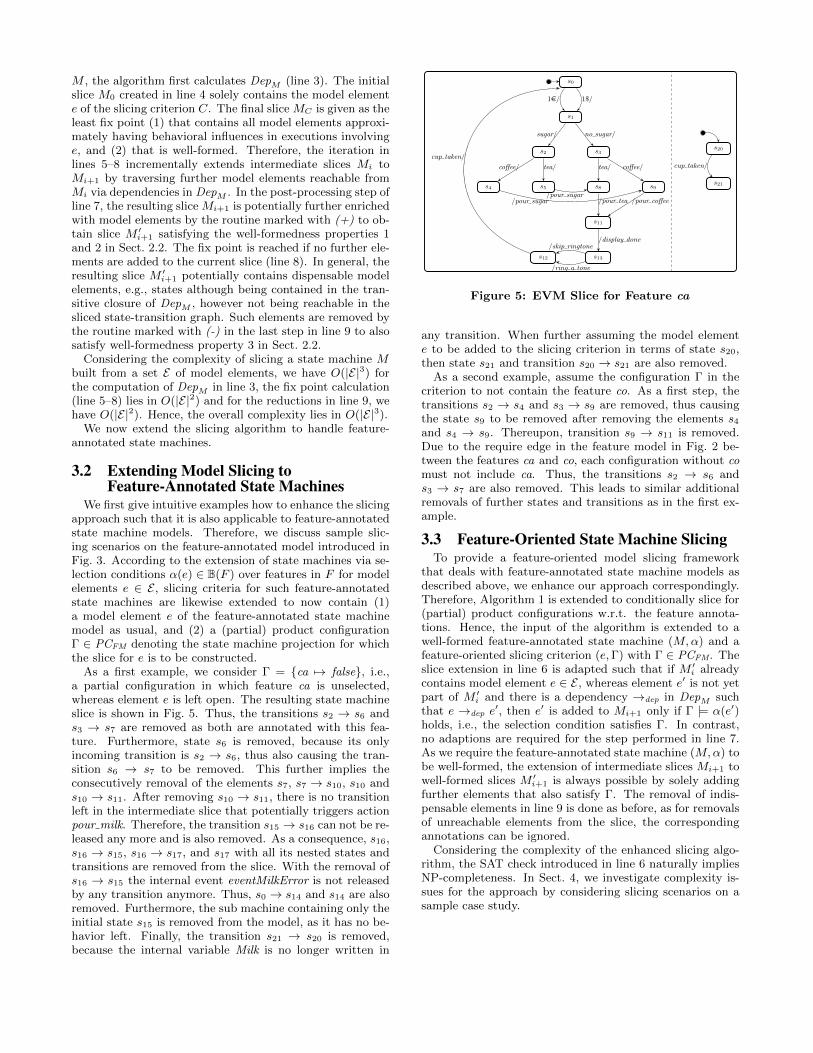
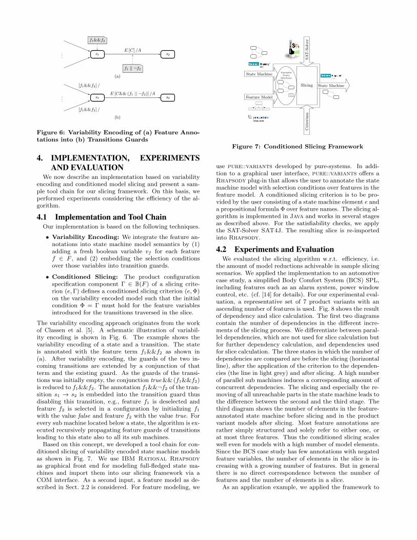
...s1 s2
f1&&f2
E [C] /A
f1 || ¬f2(a)
...s1 s2
[f1&&f2] /
[f1&&f2] /
E [C&& (f1 || ¬f2)] /A
(b)
Figure 6: Variability Encoding of (a) Feature Anno-tations into (b) Transitions Guards
4. IMPLEMENTATION, EXPERIMENTSAND EVALUATION
We now describe an implementation based on variabilityencoding and conditioned model slicing and present a sam-ple tool chain for our slicing framework. On this basis, weperformed experiments considering the efficiency of the al-gorithm.
4.1 Implementation and Tool ChainOur implementation is based on the following techniques.
• Variability Encoding: We integrate the feature an-notations into state machine model semantics by (1)adding a fresh boolean variable vf for each featuref ∈ F , and (2) embedding the selection conditionsover those variables into transition guards.
• Conditioned Slicing: The product configurationspecification component Γ ∈ B(F ) of a slicing crite-rion (e,Γ) defines a conditioned slicing criterion (e,Φ)on the variability encoded model such that the initialcondition Φ = Γ must hold for the feature variablesintroduced for the transitions traversed in the slice.
The variability encoding approach originates from the workof Classen et al. [5]. A schematic illustration of variabil-ity encoding is shown in Fig. 6. The example shows thevariability encoding of a state and a transition. The stateis annotated with the feature term f1&&f2 as shown in(a). After variability encoding, the guards of the two in-coming transitions are extended by a conjunction of thatterm and the existing guard. As the guards of the transi-tions was initially empty, the conjunction true && (f1&&f2)is reduced to f1&&f2. The annotation f1&&¬f2 of the tran-sition s1 → s2 is embedded into the transition guard thusdisabling this transition, e.g., feature f1 is deselected andfeature f2 is selected in a configuration by initializing f1with the value false and feature f2 with the value true. Forevery sub machine located below a state, the algorithm is ex-ecuted recursively propagating feature guards of transitionsleading to this state also to all its sub machines.
Based on this concept, we developed a tool chain for con-ditioned slicing of variability encoded state machine modelsas shown in Fig. 7. We use IBM Rational Rhapsodyas graphical front end for modeling full-fledged state ma-chines and import them into our slicing framework via aCOM interface. As a second input, a feature model as de-scribed in Sect. 2.2 is considered. For feature modeling, we
Cri
teri
um
SA
T-S
olv
er
State MachineSlicing
State Machine
Feature Model
VariableState
Machine
Figure 7: Conditioned Slicing Framework
use pure::variants developed by pure-systems. In addi-tion to a graphical user interface, pure::variants offers aRhapsody plug-in that allows the user to annotate the statemachine model with selection conditions over features in thefeature model. A conditioned slicing criterion is to be pro-vided by the user consisting of a state machine element e anda propositional formula Φ over feature names. The slicing al-gorithm is implemented in Java and works in several stagesas described above. For the satisfiability checks, we applythe SAT-Solver SAT4J. The resulting slice is re-importedinto Rhapsody.
4.2 Experiments and EvaluationWe evaluated the slicing algorithm w.r.t. efficiency, i.e.
the amount of model reductions achiveable in sample slicingscenarios. We applied the implementation to an automotivecase study, a simplified Body Comfort System (BCS) SPL,including features such as an alarm system, power windowcontrol, etc. (cf. [14] for details). For our experimental eval-uation, a representative set of 7 product variants with anascending number of features is used. Fig. 8 shows the resultof dependency and slice calculation. The first two diagramscontain the number of dependencies in the different incre-ments of the slicing process. We differentiate between paral-lel dependencies, which are not used for slice calculation butfor further dependency calculation, and dependencies usedfor slice calculation. The three states in which the number ofdependencies are compared are before the slicing (horizontalline), after the application of the criterion to the dependen-cies (the line in light grey) and after slicing. A high numberof parallel sub machines induces a corresponding amount ofconcurrent dependencies. The slicing and especially the re-moving of all unreachable parts in the state machine leads tothe difference between the second and the third stage. Thethird diagram shows the number of elements in the feature-annotated state machine before slicing and in the productvariant models after slicing. Most feature annotations arerather simply structured and solely refer to either one, orat most three features. Thus the conditioned slicing scaleswell even for models with a high number of model elements.Since the BCS case study has few annotations with negatedfeature variables, the number of elements in the slice is in-creasing with a growing number of features. But in generalthere is no direct correspondence between the number offeatures and the number of elements in a slice.
As an application example, we applied the framework to
15
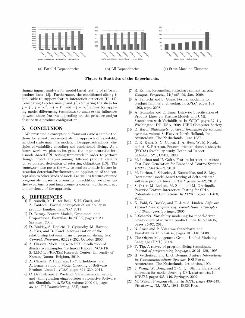
0
5000
10000
15000
20000
25000
30000
35000
40000
45000
50000
after variabilization after slicing before slicing
(a) Parallel Dependencies
0
100
200
300
400
500
600
after variabilization after Slicing before Slicing
(b) All Dependencies
0
50
100
150
200
250
300
after slicing before slicing
(c) State Machine Elements
Figure 8: Statistics of the Experiments.
change impact analysis for model-based testing of softwareproduct lines [13]. Furthermore, the conditioned slicing isapplicable to support feature interaction detection [12, 14].Considering two features f and f ′, comparing the slices forf ∧ f ′, f ∧ ¬f ′, ¬f ∧ f ′, and ¬f ∧ ¬f ′ allows for apply-ing model differencing techniques to analyze the influencesbetween those features depending on the presence and/orabsence in a product configuration.
5. CONCLUSIONWe presented a conceptional framework and a sample tool
chain for a feature-oriented slicing approach of variabilityenriched state machines models. The approach adopts prin-ciples of variability encoding and conditioned slicing. As afuture work, we plan to integrate the implementation intoa model-based SPL testing framework in order to performchange impact analysis among different product variantsfor automated derivation of retesting obligations [13]. Theframework also paves the way to semi-automatic feature in-teraction detection.Furthermore, an application of the con-cept also to other kinds of models as well as feature-orientedprogram slicing seems promising. In addition, we plan fur-ther experiments and improvements concerning the accuracyand efficiency of the approach.
6. REFERENCES[1] P. Asirelli, M. H. ter Beek, S. H. Gnesi, and
A. Fantechi. Formal description of variability inproduct families. In SPLC, 2011.
[2] D. Batory. Feature Models, Grammars, andPropositional Formulas. In SPLC, pages 7–20.Springer, 2005.
[3] D. Binkley, S. Danicic, T. Gyimothy, M. Harman,A. Kiss, and B. Korel. A formalisation of therelationship between forms of program slicing. Sci.Comput. Program., 62:228–252, October 2006.
[4] A. Classen. Modelling with FTS: a collection ofillustrative examples. Technical Report P-CS-TRSPLMC-1, PReCISE Research Center, University ofNamur, Namur, Belgium, 2010.
[5] A. Classen, P. Heymans, P.-Y. Schobbens, andA. Legay. Symbolic Model Checking of SoftwareProduct Lines. In ICSE, pages 321–330, 2011.
[6] C. Dziobek and J. Weiland. Variantenmodellierungund -konfiguration eingebetteter automotive Softwaremit Simulink. In MBEES, volume 2009-01, pages36–45. TU Braunschweig, SSE, 2009.
[7] R. Eshuis. Reconciling statechart semantics. Sci.Comput. Program., 74(3):65–99, Jan. 2009.
[8] A. Fantechi and S. Gnesi. Formal modeling forproduct families engineering. In SPLC, pages 193–202, sept. 2008.
[9] A. Gonzalez and C. Luna. Behavior Specification ofProduct Lines via Feature Models and UMLStatecharts with Variabilities. In SCCC, pages 32–41,Washington, DC, USA, 2008. IEEE Computer Society.
[10] D. Harel. Statecharts: A visual formalism for complexsystems, volume 8. Elsevier North-Holland, Inc.,Amsterdam, The Netherlands, June 1987.
[11] C. K. Kang, S. G. Cohen, J. A. Hess, W. E. Novak,and A. S. Peterson. Feature-oriented domain analysis(FODA) feasibility study. Technical ReportSEI-90-TR-21, CMU, 1990.
[12] M. Lochau and U. Goltz. Feature Interaction AwareTest Case Generation for Embedded Control Systems.ENTCS, 264:37–52, 2010.
[13] M. Lochau, I. Schaefer, J. Kamischke, and S. Lity.Incremental model-based testing of delta-orientedsoftware product lines. In TAP, pages 67–82, 2012.
[14] S. Oster, M. Lochau, M. Zink, and M. Grechanik.Pairwise Feature-Interaction Testing for SPLs:Potentials and Limitations. In FOSD, pages 6:1–6:8,2011.
[15] K. Pohl, G. Bockle, and F. J. v. d. Linden. SoftwareProduct Line Engineering: Foundations, Principlesand Techniques. Springer, 2005.
[16] I. Schaefer. Variability modelling for model-drivendevelopment of software product lines. In VAMOS,pages 85–92, 2010.
[17] N. Szasz and P. Vilanova. Statecharts andVariabilities. In VAMOS, pages 131–140, 2008.
[18] The Object Management Group. Unified ModelingLanguage (UML), 2009.
[19] F. Tip. A survey of program slicing techniques.Journal of programming languages, 3:121–189, 1995.
[20] H. Velthuijsen and L. G. Bouma. Feature Interactionsin Telecommunications Systems. IOS Press,Amsterdam, The Netherlands, 1st edition, 1994.
[21] J. Wang, W. Dong, and Z.-C. Qi. Slicing hierarchicalautomata for model checking UML statecharts. InICFEM, pages 435–446. Springer, 2002.
[22] M. Weiser. Program slicing. In ICSE, pages 439–449,Piscataway, NJ, USA, 1981. IEEE Press.
16
Comparing Program Comprehension of Physically andVirtually Separated Concerns
Janet Siegmund∗
University of Magdeburg,Germany
Christian KästnerPhilipps University Marburg,
Germany
Jörg Liebig, Sven ApelUniversity of Passau,
Germany
ABSTRACTIt is common believe that separating source code along con-cerns or features improves program comprehension of sourcecode. However, empirical evidence is mostly missing. In thispaper, we design a controlled experiment to evaluate thatbelieve for feature-oriented programming based on main-tenance tasks with human participants. We validate ourexperiment with a pilot study, which already preliminarilyconfirms that students use different strategies to completemaintenance tasks.
KeywordsSeparation of Concerns, Program Comprehension, Feature-House, Ifdef
1. INTRODUCTIONSeparation of concerns is an essential strategy to imple-
ment understandable and maintainable software [21]. Be-sides classic programming mechanisms, such as proceduresand objects, many novel mechanisms for separation of con-cerns have been proposed in the past: components [10],aspects [14], hyper-modules [23], and so forth. Similarly,feature-oriented programming (FOP) advocates to structuresoftware along the features it provides (i.e., user-visible char-acteristic of a software system) [5, 22]. That is, featuresare made explicit in design and code in the form of featuremodules—one feature module implementing one feature.
In our field, it is common to believe that separating codealong features improves program comprehension. However,program comprehension is an internal cognitive process thatwe cannot observe directly [15]. Thus, it is not sufficient torely on plausibility arguments in the debate of whether someconcept or mechanism improves program comprehension.Instead, we need controlled experiments to measure it [3, 8].
In this paper, we set out to evaluate whether separat-ing features into separate feature modules improves program
∗The author published previous work as Janet Feigenspan.
Permission to make digital or hard copies of all or part of this work forpersonal or classroom use is granted without fee provided that copies arenot made or distributed for profit or commercial advantage and that copiesbear this notice and the full citation on the first page. To copy otherwise, torepublish, to post on servers or to redistribute to lists, requires prior specificpermission and/or a fee.FOSD’12, September 24–25, 2012, Dresden, Germany.Copyright 2012 ACM 978-1-4503-1309-4/12/09 ...$15.00.
comprehension. In particular, we concentrate on the mech-anism of FOP as implemented in the tool FeatureHouse [2].In FOP, developers can trace each feature to one physi-cally separated feature module. We compare the effect ofphysical separation on program comprehension to an imple-mentation in which features are annotated with conditional-compilation directives such as #ifdefs. We speak of virtualseparation, because the #ifdef directives allow developers totrace a feature to its scattered implementation throughoutthe source code.
To this end, we designed a controlled experiment, in whichwe observe how participants comprehend source code dur-ing maintenance tasks. As material, we used two compara-ble software systems—one decomposed physically in termsof feature modules and one annotated with preprocessor di-rectives. Based on experimental results, we can give rec-ommendations on which technique of separating code alongfeatures is suitable for which task and how to improve them.
Our contributions are twofold:• We design a reusable experiment to evaluate the im-
pact of physical separation with FeatureHouse on pro-gram comprehension.
• We conducted a pilot study to validate the experimentand prepare a large scale run.
We plan to execute the experiment with a larger sam-ple in the fall term. We appreciate feedback and addi-tional research questions to evaluate. We also invite oth-ers to conduct this or similar experiments. Therefore, weprovide all necessary material online at http://fosd.net/
experiments.
2. PHYSICAL VS. VIRTUAL SEPARATIONTo separate crosscutting concerns, several programming
techniques were developed, including aspect-oriented pro-gramming [14] and FOP [22], which aim at dividing thesource code into modules regarding concerns or features.
FOP as implemented by AHEAD [5] and FeatureHouse [2]separates code belonging to different features physically intoseparate folders, one folder per feature (and per interac-tion). Each folder may contain multiple packages and (par-tial) classes that implement the corresponding feature. Togenerate a product for a specific feature selection, the codefrom the selected features is composed, such that classes andmethods that have the same name are merged by superim-position [2].
As a base line for comparison, we use virtual separationwith #ifdef directives, in which features are merely mappedto code fragments with annotations in the source code. A
17
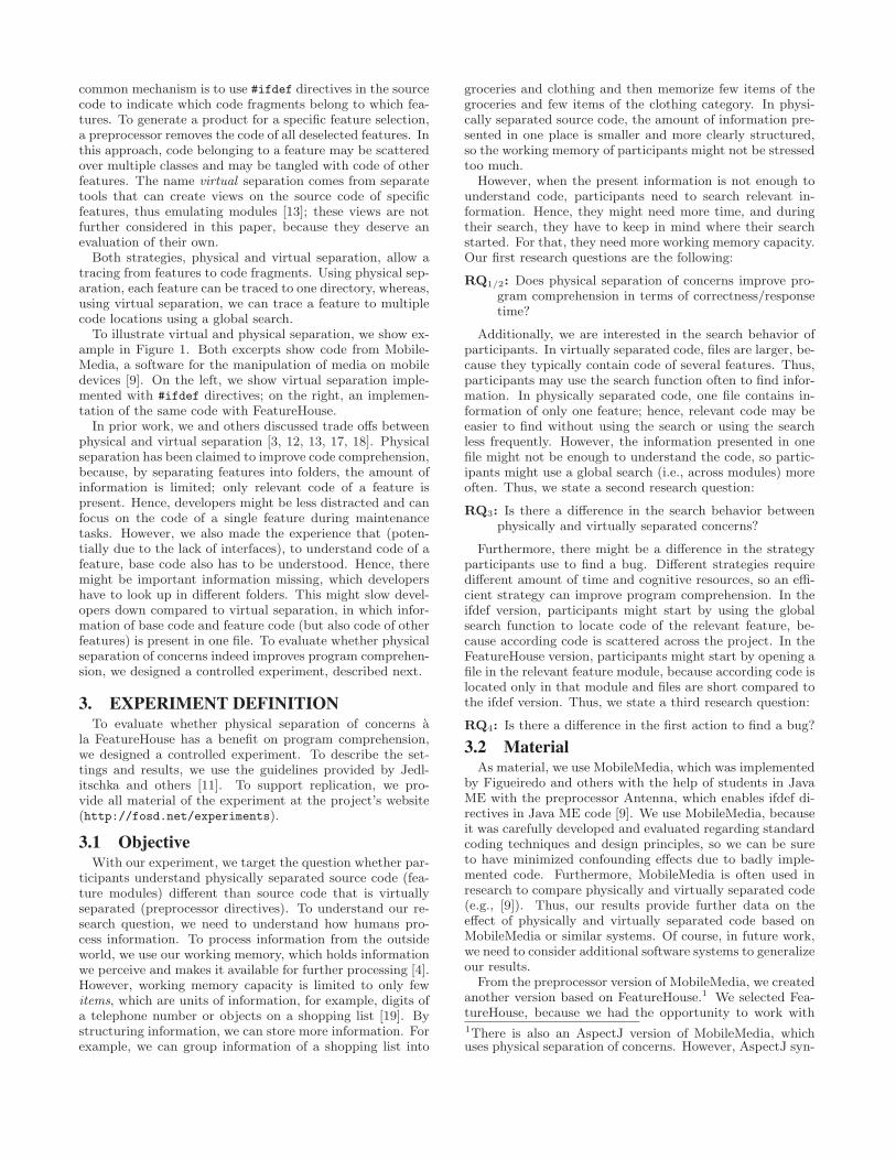
common mechanism is to use #ifdef directives in the sourcecode to indicate which code fragments belong to which fea-tures. To generate a product for a specific feature selection,a preprocessor removes the code of all deselected features. Inthis approach, code belonging to a feature may be scatteredover multiple classes and may be tangled with code of otherfeatures. The name virtual separation comes from separatetools that can create views on the source code of specificfeatures, thus emulating modules [13]; these views are notfurther considered in this paper, because they deserve anevaluation of their own.
Both strategies, physical and virtual separation, allow atracing from features to code fragments. Using physical sep-aration, each feature can be traced to one directory, whereas,using virtual separation, we can trace a feature to multiplecode locations using a global search.
To illustrate virtual and physical separation, we show ex-ample in Figure 1. Both excerpts show code from Mobile-Media, a software for the manipulation of media on mobiledevices [9]. On the left, we show virtual separation imple-mented with #ifdef directives; on the right, an implemen-tation of the same code with FeatureHouse.
In prior work, we and others discussed trade offs betweenphysical and virtual separation [3, 12, 13, 17, 18]. Physicalseparation has been claimed to improve code comprehension,because, by separating features into folders, the amount ofinformation is limited; only relevant code of a feature ispresent. Hence, developers might be less distracted and canfocus on the code of a single feature during maintenancetasks. However, we also made the experience that (poten-tially due to the lack of interfaces), to understand code of afeature, base code also has to be understood. Hence, theremight be important information missing, which developershave to look up in different folders. This might slow devel-opers down compared to virtual separation, in which infor-mation of base code and feature code (but also code of otherfeatures) is present in one file. To evaluate whether physicalseparation of concerns indeed improves program comprehen-sion, we designed a controlled experiment, described next.
3. EXPERIMENT DEFINITIONTo evaluate whether physical separation of concerns a
la FeatureHouse has a benefit on program comprehension,we designed a controlled experiment. To describe the set-tings and results, we use the guidelines provided by Jedl-itschka and others [11]. To support replication, we pro-vide all material of the experiment at the project’s website(http://fosd.net/experiments).
3.1 ObjectiveWith our experiment, we target the question whether par-
ticipants understand physically separated source code (fea-ture modules) different than source code that is virtuallyseparated (preprocessor directives). To understand our re-search question, we need to understand how humans pro-cess information. To process information from the outsideworld, we use our working memory, which holds informationwe perceive and makes it available for further processing [4].However, working memory capacity is limited to only fewitems, which are units of information, for example, digits ofa telephone number or objects on a shopping list [19]. Bystructuring information, we can store more information. Forexample, we can group information of a shopping list into
groceries and clothing and then memorize few items of thegroceries and few items of the clothing category. In physi-cally separated source code, the amount of information pre-sented in one place is smaller and more clearly structured,so the working memory of participants might not be stressedtoo much.
However, when the present information is not enough tounderstand code, participants need to search relevant in-formation. Hence, they might need more time, and duringtheir search, they have to keep in mind where their searchstarted. For that, they need more working memory capacity.Our first research questions are the following:
RQ1/2: Does physical separation of concerns improve pro-gram comprehension in terms of correctness/responsetime?
Additionally, we are interested in the search behavior ofparticipants. In virtually separated code, files are larger, be-cause they typically contain code of several features. Thus,participants may use the search function often to find infor-mation. In physically separated code, one file contains in-formation of only one feature; hence, relevant code may beeasier to find without using the search or using the searchless frequently. However, the information presented in onefile might not be enough to understand the code, so partic-ipants might use a global search (i.e., across modules) moreoften. Thus, we state a second research question:
RQ3: Is there a difference in the search behavior betweenphysically and virtually separated concerns?
Furthermore, there might be a difference in the strategyparticipants use to find a bug. Different strategies requiredifferent amount of time and cognitive resources, so an effi-cient strategy can improve program comprehension. In theifdef version, participants might start by using the globalsearch function to locate code of the relevant feature, be-cause according code is scattered across the project. In theFeatureHouse version, participants might start by opening afile in the relevant feature module, because according code islocated only in that module and files are short compared tothe ifdef version. Thus, we state a third research question:
RQ4: Is there a difference in the first action to find a bug?
3.2 MaterialAs material, we use MobileMedia, which was implemented
by Figueiredo and others with the help of students in JavaME with the preprocessor Antenna, which enables ifdef di-rectives in Java ME code [9]. We use MobileMedia, becauseit was carefully developed and evaluated regarding standardcoding techniques and design principles, so we can be sureto have minimized confounding effects due to badly imple-mented code. Furthermore, MobileMedia is often used inresearch to compare physically and virtually separated code(e.g., [9]). Thus, our results provide further data on theeffect of physically and virtually separated code based onMobileMedia or similar systems. Of course, in future work,we need to consider additional software systems to generalizeour results.
From the preprocessor version of MobileMedia, we createdanother version based on FeatureHouse.1 We selected Fea-tureHouse, because we had the opportunity to work with1There is also an AspectJ version of MobileMedia, whichuses physical separation of concerns. However, AspectJ syn-
18
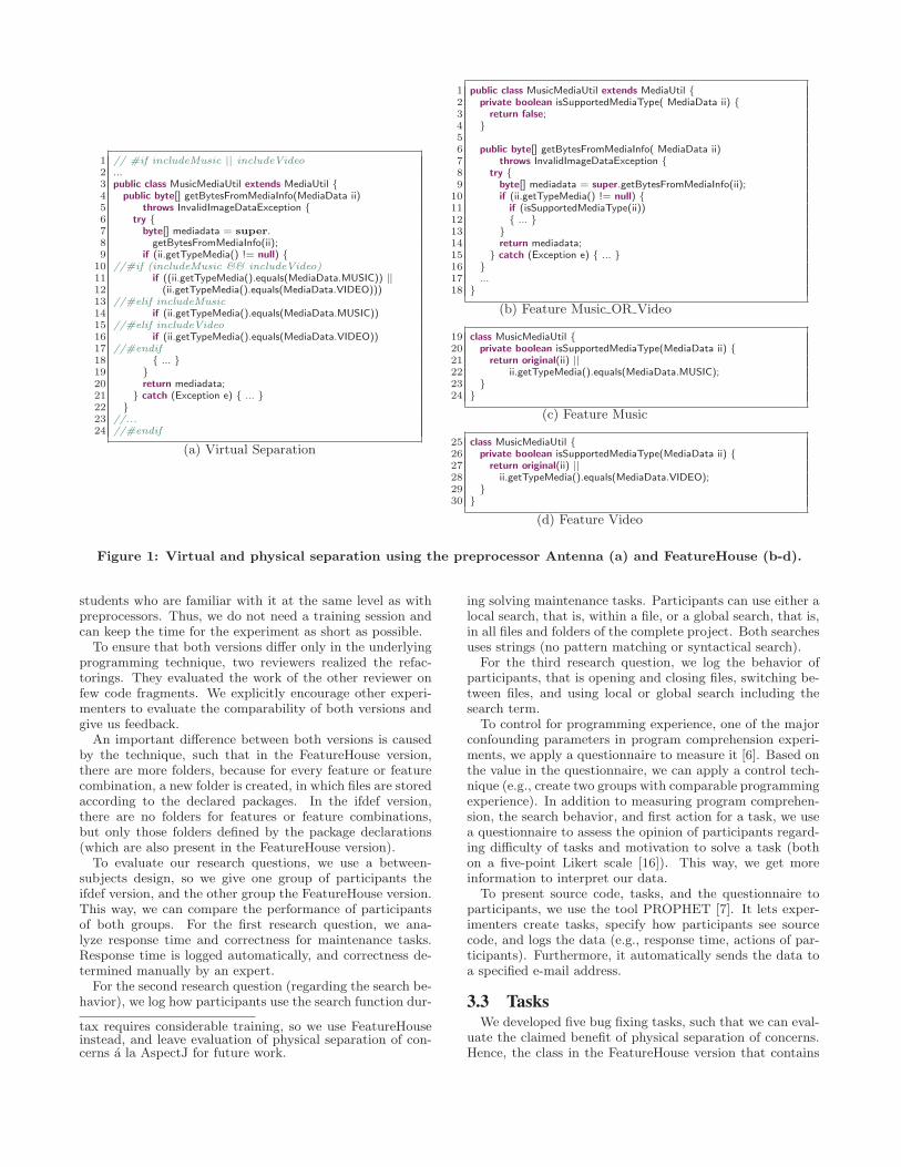
1 // #if includeMusic || includeVideo2 ...3 public class MusicMediaUtil extends MediaUtil {4 public byte[] getBytesFromMediaInfo(MediaData ii)5 throws InvalidImageDataException {6 try {7 byte[] mediadata = super.8 getBytesFromMediaInfo(ii);9 if (ii.getTypeMedia() != null) {
10 //#if (includeMusic && includeVideo)11 if ((ii.getTypeMedia().equals(MediaData.MUSIC)) ||12 (ii.getTypeMedia().equals(MediaData.VIDEO)))13 //#elif includeMusic14 if (ii.getTypeMedia().equals(MediaData.MUSIC))15 //#elif includeVideo16 if (ii.getTypeMedia().equals(MediaData.VIDEO))17 //#endif18 { ... }19 }20 return mediadata;21 } catch (Exception e) { ... }22 }23 //...24 //#endif
(a) Virtual Separation
1 public class MusicMediaUtil extends MediaUtil {2 private boolean isSupportedMediaType( MediaData ii) {3 return false;4 }56 public byte[] getBytesFromMediaInfo( MediaData ii)7 throws InvalidImageDataException {8 try {9 byte[] mediadata = super.getBytesFromMediaInfo(ii);
10 if (ii.getTypeMedia() != null) {11 if (isSupportedMediaType(ii))12 { ... }13 }14 return mediadata;15 } catch (Exception e) { ... }16 }17 ...18 }
(b) Feature Music OR Video
19 class MusicMediaUtil {20 private boolean isSupportedMediaType(MediaData ii) {21 return original(ii) ||22 ii.getTypeMedia().equals(MediaData.MUSIC);23 }24 }
(c) Feature Music
25 class MusicMediaUtil {26 private boolean isSupportedMediaType(MediaData ii) {27 return original(ii) ||28 ii.getTypeMedia().equals(MediaData.VIDEO);29 }30 }
(d) Feature Video
Figure 1: Virtual and physical separation using the preprocessor Antenna (a) and FeatureHouse (b-d).
students who are familiar with it at the same level as withpreprocessors. Thus, we do not need a training session andcan keep the time for the experiment as short as possible.
To ensure that both versions differ only in the underlyingprogramming technique, two reviewers realized the refac-torings. They evaluated the work of the other reviewer onfew code fragments. We explicitly encourage other experi-menters to evaluate the comparability of both versions andgive us feedback.
An important difference between both versions is causedby the technique, such that in the FeatureHouse version,there are more folders, because for every feature or featurecombination, a new folder is created, in which files are storedaccording to the declared packages. In the ifdef version,there are no folders for features or feature combinations,but only those folders defined by the package declarations(which are also present in the FeatureHouse version).
To evaluate our research questions, we use a between-subjects design, so we give one group of participants theifdef version, and the other group the FeatureHouse version.This way, we can compare the performance of participantsof both groups. For the first research question, we ana-lyze response time and correctness for maintenance tasks.Response time is logged automatically, and correctness de-termined manually by an expert.
For the second research question (regarding the search be-havior), we log how participants use the search function dur-
tax requires considerable training, so we use FeatureHouseinstead, and leave evaluation of physical separation of con-cerns a la AspectJ for future work.
ing solving maintenance tasks. Participants can use either alocal search, that is, within a file, or a global search, that is,in all files and folders of the complete project. Both searchesuses strings (no pattern matching or syntactical search).
For the third research question, we log the behavior ofparticipants, that is opening and closing files, switching be-tween files, and using local or global search including thesearch term.
To control for programming experience, one of the majorconfounding parameters in program comprehension experi-ments, we apply a questionnaire to measure it [6]. Based onthe value in the questionnaire, we can apply a control tech-nique (e.g., create two groups with comparable programmingexperience). In addition to measuring program comprehen-sion, the search behavior, and first action for a task, we usea questionnaire to assess the opinion of participants regard-ing difficulty of tasks and motivation to solve a task (bothon a five-point Likert scale [16]). This way, we get moreinformation to interpret our data.
To present source code, tasks, and the questionnaire toparticipants, we use the tool PROPHET [7]. It lets exper-imenters create tasks, specify how participants see sourcecode, and logs the data (e.g., response time, actions of par-ticipants). Furthermore, it automatically sends the data toa specified e-mail address.
3.3 TasksWe developed five bug fixing tasks, such that we can eval-
uate the claimed benefit of physical separation of concerns.Hence, the class in the FeatureHouse version that contains
19
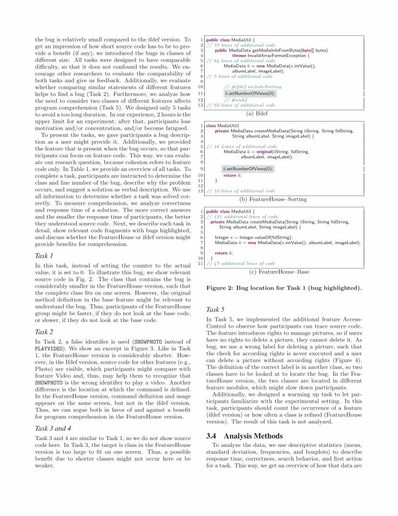
the bug is relatively small compared to the ifdef version. Toget an impression of how short source code has to be to pro-vide a benefit (if any), we introduced the bugs in classes ofdifferent size. All tasks were designed to have comparabledifficulty, so that it does not confound the results. We en-courage other researchers to evaluate the comparability ofboth tasks and give us feedback. Additionally, we evaluatewhether comparing similar statements of different featureshelps to find a bug (Task 2). Furthermore, we analyze howthe need to consider two classes of different features affectsprogram comprehension (Task 5). We designed only 5 tasksto avoid a too long duration. In our experience, 2 hours is theupper limit for an experiment; after that, participants losemotivation and/or concentration, and/or become fatigued.
To present the tasks, we gave participants a bug descrip-tion as a user might provide it. Additionally, we providedthe feature that is present when the bug occurs, so that par-ticipants can focus on feature code. This way, we can evalu-ate our research question, because cohesion refers to featurecode only. In Table 1, we provide an overview of all tasks. Tocomplete a task, participants are instructed to determine theclass and line number of the bug, describe why the problemoccurs, and suggest a solution as verbal description. We useall information to determine whether a task was solved cor-rectly. To measure comprehension, we analyze correctnessand response time of a solution. The more correct answersand the smaller the response time of participants, the betterthey understood source code. Next, we describe each task indetail, show relevant code fragments with bugs highlighted,and discuss whether the FeatureHouse or ifdef version mightprovide benefits for comprehension.
Task 1In this task, instead of setting the counter to the actualvalue, it is set to 0. To illustrate this bug, we show relevantsource code in Fig. 2. The class that contains the bug isconsiderably smaller in the FeatureHouse version, such thatthe complete class fits on one screen. However, the originalmethod definition in the base feature might be relevant tounderstand the bug. Thus, participants of the FeatureHousegroup might be faster, if they do not look at the base code,or slower, if they do not look at the base code.
Task 2In Task 2, a false identifier is used (SHOWPHOTO instead ofPLAYVIDEO). We show an excerpt in Figure 3. Like in Task1, the FeatureHouse version is considerably shorter. How-ever, in the Ifdef version, source code for other features (e.g.,Photo) are visible, which participants might compare withfeature Video and, thus, may help them to recognize thatSHOWPHOTO is the wrong identifier to play a video. Anotherdifference is the location at which the command is defined.In the FeatureHouse version, command definition and usageappears on the same screen, but not in the ifdef version.Thus, we can argue both in favor of and against a benefitfor program comprehension in the FeatureHouse version.
Task 3 and 4Task 3 and 4 are similar to Task 1, so we do not show sourcecode here. In Task 3, the target is class in the FeatureHouseversion is too large to fit on one screen. Thus, a possiblebenefit due to shorter classes might not occur here or beweaker.
1 public class MediaUtil {2 // 73 lines of additional code3 public MediaData getMediaInfoFromBytes(byte[] bytes)4 throws InvalidArrayFormatException {5 // 64 lines of additional code6 MediaData ii = new MediaData(x.intValue(),7 albumLabel, imageLabel);8 // 5 lines of additional code9
10 // #ifdef includeSorting
11 ii.setNumberOfViews(0);
12 // #endif13 // 62 lines of additional code
(a) Ifdef
1 class MediaUtil{2 private MediaData createMediaData(String iiString, String fidString,3 String albumLabel, String imageLabel) {45 // 16 Lines of additional code6 MediaData ii = original(iiString, fidString,7 albumLabel, imageLabel);8
9 ii.setNumberOfViews(0);
10 return ii;11 }1213 // 10 lines of additional code
(b) FeatureHouse–Sorting
1 public class MediaUtil {2 // 121 additional lines of code3 private MediaData createMediaData(String iiString, String fidString,4 String albumLabel, String imageLabel) {56 Integer x = Integer.valueOf(fidString);7 MediaData ii = new MediaData(x.intValue(), albumLabel, imageLabel);89 return ii;
10 }11 // 47 additional lines of code
(c) FeatureHouse–Base
Figure 2: Bug location for Task 1 (bug highlighted).
Task 5In Task 5, we implemented the additional feature Access-Control to observe how participants can trace source code.The feature introduces rights to manage pictures, so if usershave no rights to delete a picture, they cannot delete it. Asbug, we use a wrong label for deleting a picture, such thatthe check for according rights is never executed and a usercan delete a picture without according rights (Figure 4).The definition of the correct label is in another class, so twoclasses have to be looked at to locate the bug. In the Fea-tureHouse version, the two classes are located in differentfeature modules, which might slow down participants.
Additionally, we designed a warming up task to let par-ticipants familiarize with the experimental setting. In thistask, participants should count the occurrence of a feature(ifdef version) or how often a class is refined (FeatureHouseversion). The result of this task is not analyzed.
3.4 Analysis MethodsTo analyze the data, we use descriptive statistics (mean,
standard deviation, frequencies, and boxplots) to describeresponse time, correctness, search behavior, and first actionfor a task. This way, we get an overview of how that data are
20
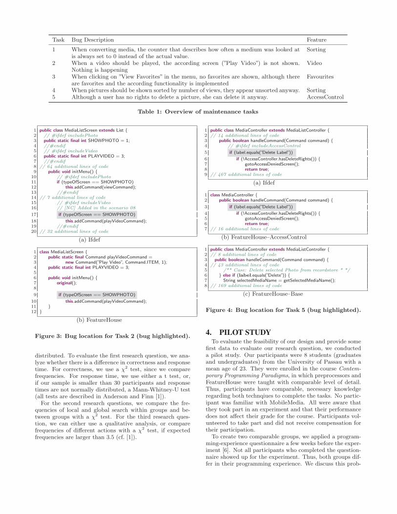
Task Bug Description Feature
1 When converting media, the counter that describes how often a medium was looked atis always set to 0 instead of the actual value.
Sorting
2 When a video should be played, the according screen (”Play Video”) is not shown.Nothing is happening
Video
3 When clicking on ”View Favorites” in the menu, no favorites are shown, although thereare favorites and the according functionality is implemented
Favourites
4 When pictures should be shown sorted by number of views, they appear unsorted anyway. Sorting5 Although a user has no rights to delete a picture, she can delete it anyway. AccessControl
Table 1: Overview of maintenance tasks
1 public class MediaListScreen extends List {2 // #ifdef includePhoto3 public static final int SHOWPHOTO = 1;4 //#endif5 // #ifdef includeVideo6 public static final int PLAYVIDEO = 3;7 //#endif8 // 64 additional lines of code9 public void initMenu() {
10 // #ifdef includePhoto11 if (typeOfScreen == SHOWPHOTO)12 this.addCommand(viewCommand);13 //#endif14 // 7 additional lines of code15 // #ifdef includeVideo16 // [NC] Added in the scenario 08
17 if (typeOfScreen == SHOWPHOTO)
18 this.addCommand(playVideoCommand);19 //#endif20 // 32 additional lines of code
(a) Ifdef
1 class MediaListScreen {2 public static final Command playVideoCommand =3 new Command(”Play Video”, Command.ITEM, 1);4 public static final int PLAYVIDEO = 3;56 public void initMenu() {7 original();8
9 if (typeOfScreen == SHOWPHOTO)
10 this.addCommand(playVideoCommand);11 }12 }
(b) FeatureHouse
Figure 3: Bug location for Task 2 (bug highlighted).
distributed. To evaluate the first research question, we ana-lyze whether there is a difference in correctness and responsetime. For correctness, we use a χ2 test, since we comparefrequencies. For response time, we use either a t test, or,if our sample is smaller than 30 participants and responsetimes are not normally distributed, a Mann-Whitney-U test(all tests are described in Anderson and Finn [1]).
For the second research questions, we compare the fre-quencies of local and global search within groups and be-tween groups with a χ2 test. For the third research ques-tion, we can either use a qualitative analysis, or comparefrequencies of different actions with a χ2 test, if expectedfrequencies are larger than 3.5 (cf. [1]).
1 public class MediaController extends MediaListController {2 // 14 additional lines of code3 public boolean handleCommand(Command command) {4 // #ifdef includeAccessControl
5 if (label.equals(”Delete Label”))
6 if (!AccessController.hasDeleteRights()) {7 gotoAccessDeniedScreen();8 return true;9 // 467 additional lines of code
(a) Ifdef
1 class MediaController {2 public boolean handleCommand(Command command) {3 if (label.equals(”Delete Label”))
4 if (!AccessController.hasDeleteRights()) {5 gotoAccessDeniedScreen();6 return true;7 // 16 additional lines of code
(b) FeatureHouse–AccessControl
1 public class MediaController extends MediaListController {2 // 8 additional lines of code3 public boolean handleCommand(Command command) {4 // 43 additional lines of code5 /** Case: Delete selected Photo from recordstore * */6 } else if (label.equals(”Delete”)) {7 String selectedMediaName = getSelectedMediaName();8 // 169 additional lines of code
(c) FeatureHouse–Base
Figure 4: Bug location for Task 5 (bug highlighted).
4. PILOT STUDYTo evaluate the feasibility of our design and provide some
first data to evaluate our research question, we conducteda pilot study. Our participants were 8 students (graduatesand undergraduates) from the University of Passau with amean age of 23. They were enrolled in the course Contem-porary Programming Paradigms, in which preprocessors andFeatureHouse were taught with comparable level of detail.Thus, participants have comparable, necessary knowledgeregarding both technqiues to complete the tasks. No partic-ipant was familiar with MobileMedia. All were aware thatthey took part in an experiment and that their performancedoes not affect their grade for the course. Participants vol-unteered to take part and did not receive compensation fortheir participation.
To create two comparable groups, we applied a program-ming-experience questionnaire a few weeks before the exper-iment [6]. Not all participants who completed the question-naire showed up for the experiment. Thus, both groups dif-fer in their programming experience. We discuss this prob-
21
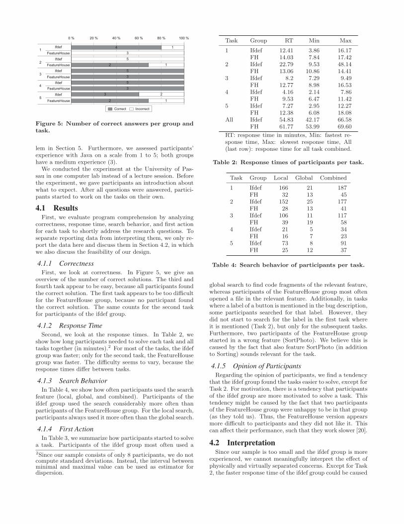
3
23535
15
0 % 100 %80 %60 %40 %20 %
1
2
5
4
3
Ifdef
FeatureHouseIfdef
Ifdef
IfdefFeatureHouse
FeatureHouse
Ifdef
FeatureHouse
FeatureHouse 2
12
3
14
Correct Incorrect
Figure 5: Number of correct answers per group andtask.
lem in Section 5. Furthermore, we assessed participants’experience with Java on a scale from 1 to 5; both groupshave a medium experience (3).
We conducted the experiment at the University of Pas-sau in one computer lab instead of a lecture session. Beforethe experiment, we gave participants an introduction aboutwhat to expect. After all questions were answered, partici-pants started to work on the tasks on their own.
4.1 ResultsFirst, we evaluate program comprehension by analyzing
correctness, response time, search behavior, and first actionfor each task to shortly address the research questions. Toseparate reporting data from interpreting them, we only re-port the data here and discuss them in Section 4.2, in whichwe also discuss the feasibility of our design.
4.1.1 CorrectnessFirst, we look at correctness. In Figure 5, we give an
overview of the number of correct solutions. The third andfourth task appear to be easy, because all participants foundthe correct solution. The first task appears to be too difficultfor the FeatureHouse group, because no participant foundthe correct solution. The same counts for the second taskfor participants of the ifdef group.
4.1.2 Response TimeSecond, we look at the response times. In Table 2, we
show how long participants needed to solve each task and alltasks together (in minutes).2 For most of the tasks, the ifdefgroup was faster; only for the second task, the FeatureHousegroup was faster. The difficulty seems to vary, because theresponse times differ between tasks.
4.1.3 Search BehaviorIn Table 4, we show how often participants used the search
feature (local, global, and combined). Participants of theifdef group used the search considerably more often thanparticipants of the FeatureHouse group. For the local search,participants always used it more often than the global search.
4.1.4 First ActionIn Table 3, we summarize how participants started to solve
a task. Participants of the ifdef group most often used a
2Since our sample consists of only 8 participants, we do notcompute standard deviations. Instead, the interval betweenminimal and maximal value can be used as estimator fordispersion.
Task Group RT Min Max
1 Ifdef 12.41 3.86 16.17FH 14.03 7.84 17.42
2 Ifdef 22.79 9.53 48.14FH 13.06 10.86 14.41
3 Ifdef 8.2 7.29 9.49FH 12.77 8.98 16.53
4 Ifdef 4.16 2.14 7.86FH 9.53 6.47 11.42
5 Ifdef 7.27 2.95 12.27FH 12.38 6.08 18.08
All Ifdef 54.83 42.17 66.58FH 61.77 53.99 69.60
RT: response time in minutes, Min: fastest re-sponse time, Max: slowest response time, All(last row): response time for all task combined.
Table 2: Response times of participants per task.
Task Group Local Global Combined
1 Ifdef 166 21 187FH 32 13 45
2 Ifdef 152 25 177FH 28 13 41
3 Ifdef 106 11 117FH 39 19 58
4 Ifdef 21 5 34FH 16 7 23
5 Ifdef 73 8 91FH 25 12 37
Table 4: Search behavior of participants per task.
global search to find code fragments of the relevant feature,whereas participants of the FeatureHouse group most oftenopened a file in the relevant feature. Additionally, in taskswhere a label of a button is mentioned in the bug description,some participants searched for that label. However, theydid not start to search for the label in the first task whereit is mentioned (Task 2), but only for the subsequent tasks.Furthermore, two participants of the FeatureHouse groupstarted in a wrong feature (SortPhoto). We believe this iscaused by the fact that also feature SortPhoto (in additionto Sorting) sounds relevant for the task.
4.1.5 Opinion of ParticipantsRegarding the opinion of participants, we find a tendency
that the ifdef group found the tasks easier to solve, except forTask 2. For motivation, there is a tendency that participantsof the ifdef group are more motivated to solve a task. Thistendency might be caused by the fact that two participantsof the FeatureHouse group were unhappy to be in that group(as they told us). Thus, the FeatureHouse version appearsmore difficult to participants and they did not like it. Thiscan affect their performance, such that they work slower [20].
4.2 InterpretationSince our sample is too small and the ifdef group is more
experienced, we cannot meaningfully interpret the effect ofphysically and virtually separated concerns. Except for Task2, the faster response time of the ifdef group could be caused
22
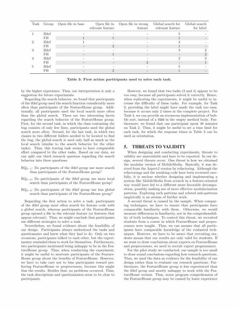
Task Group Open file in base Open file inrelevant feature
Open file in wrongfeature
Global search forrelevant feature
Global searchfor label
1 Ifdef - - - 5 -FH 1 1 - 1 -
2 Ifdef 1 - - 4 -FH - 2 - 1 -
3 Ifdef - - - 3 2FH - 1 - - 2
4 Ifdef - - - 2 3FH - - 2 - 1
5 Ifdef - - - 5 -FH - 2 - 1 -
Table 3: First action participants used to solve each task.
by the higher experience. Thus, our interpretation is only asuggestion for future experiments.
Regarding the search behavior, we found that participantsof the ifdef group used the search function considerably moreoften than participants of the FeatureHouse group. Addi-tionally, all participants used the local search more oftenthan the global search. There are two interesting facetsregarding the search behavior of the FeatureHouse group.First, for the second task, in which the class containing thebug consists of only few lines, participants used the globalsearch more often. Second, for the last task, in which twoclasses in two different folders needed to be located to findthe bug, the global search is used only half as much as thelocal search (similar to the search behavior for the othertasks). Thus, this tracing task seems to have comparableeffort compared to the other tasks. Based on our data, wecan split our third research question regarding the searchbehavior into three questions:
RQ3−1: Do participants of the ifdef group use more searchthan participants of the FeatureHouse group?
RQ3−2: Do participants of the ifdef group use more localsearch than participants of the FeatureHouse group?
RQ3−3: Do participants of the ifdef group use less globalsearch than participants of the FeatureHouse group?
Regarding the first action to solve a task, participantsof the ifdef group most often search for feature code witha global search, whereas participants of the FeatureHousegroup opened a file in the relevant feature (or features thatappear relevant). Thus, we might conclude that participantsuse different strategies to solve a task.
Nevertheless, we found evidence about the feasibility ofour design. Participants always understood the tasks andquestionnaire and knew what they had to do. Only on twooccasions, participants talked to each other, but the experi-menter reminded them to work for themselves. Furthermore,two participants mentioned being unhappy to be in the Fea-tureHouse group. Thus, when conducting the experiment,it might be useful to motivate participants of the Feature-House group about the benefits of FeatureHouse. However,we have to take care not to bias participants toward pre-ferring FeatureHouse or preprocessors, because this mightbias the results. Besides that, no problems occurred. Thus,the task descriptions and questionnaires seem to be clear toparticipants.
However, we found that two tasks (3 and 4) appear to betoo easy, because all participants solved it correctly. Hence,when replicating the experiments, it might be useful to in-crease the difficulty of these tasks. For example, for Task3, providing the label might have made the task too easy,because it occurs only 2 times in the complete project. ForTask 4, we can provide an erroneous implementation of bub-ble sort, instead of a TODO in the empty method body. Fur-thermore, we found that one participant spent 48 minuteson Task 2. Thus, it might be useful to set a time limit foreach task, for which the response times in Table 2 can beused as orientation.
5. THREATS TO VALIDITYWhen designing and conducting experiments, threats to
validity are unavoidable and have to be reported. In our de-sign, several threats occur. One threat is how we obtainedthe modular version of MobileMedia. Basically, it was de-rived from the AspectJ version by refactoring. Although therefactorings and the resulting code have been reviewed care-fully, it is unclear whether designing and implementing asystem like MobileMedia from scratch in a feature-orientedway would have led to a different more favorable decompo-sition, possibly making use of more effective modularizationpatterns. Exploring such patterns and related anti-patternsempirically is an avenue of further work.
A second threat is caused by the sample. When compar-ing techniques, we have to ensure that participants havecomparable familiarity with them. Otherwise, we wouldmeasure differences in familiarity, not in the comprehensibil-ity of both techniques. To control this threat, we recruitedstudents from a course in which FeatureHouse and prepro-cessors were taught. Thus, we can assume that all partic-ipants have comparable knowledge of the evaluated tech-niques. However, we have to be aware that recruiting stu-dents means that our results are only valid for students. Ifwe want to draw conclusions about experts on FeatureHouseand preprocessors, we need to recruit expert programmers.
For the pilot study we conducted, our sample is too smallto draw sound conclusions regarding how research questions.Thus, we used the data as evidence for the feasibility of ourdesign rather than to evaluate our research questions. Fur-thermore, the FeatureHouse group is less experienced thanthe ifdef group and mostly unhappy to work with the Fea-tureHouse version. Thus, worse program comprehension ofthe FeatureHouse group may be caused by lower experience
23
or happiness, not the underlying technique. To avoid misin-terpreting the data, we only carefully described tendenciesregarding benefits and drawbacks of physically and virtuallyseparated code.
6. CONCLUSIONSSeparation of concerns is supposed to improve program
comprehension. However, there are no empirical studies thatevaluate comprehensibility of physically separated code. Toclose this gap, we presented an experimental design to com-pare program comprehension of physical and virtual sepa-ration of concerns. We refactored the ifdef version of Mo-bileMedia (virtually separated) to a FeatureHouse version(physically separated). In a pilot study with 8 students,we showed the feasibility of our design. Our next step is toreplicate the experiment with a larger sample. Furthermore,we encourage other researchers to replicate our experiment.With sound empirical results, we can give recommendationon which technique of separating code is suitable for whichtask and how separation of concerns can be improved.
7. ACKNOWLEDGMENTSThanks to the reviewers who helped to improve this paper.
Siegmund’s work is funded by BMBF project 01IM10002B,Kastner’s work partly by ERC grant #203099, and Apel’swork by the German Research Foundation (AP 206/2, AP206/4, and LE 912/13).
8. REFERENCES[1] T. Anderson and J. Finn. The New Statistical Analysis
of Data. Springer, 1996.
[2] S. Apel, C. Kastner, and C. Lengauer. FeatureHouse:Language-Independent, Automatic SoftwareComposition. In Proc. Int’l Conf. SoftwareEngineering (ICSE), pages 221–231. IEEE, 2009.
[3] S. Apel, C. Kastner, and S. Trujillo. On the Necessityof Empirical Studies in the Assessment ofModularization Mechanisms for CrosscuttingConcerns. In ACoM ’07: Proceedings of the 1stInternational Workshop on Assessment ofContemporary Modularization Techniques, pages 1–7.IEEE, 2007.
[4] A. D. Baddeley. Is Working Memory still Working?The American Psychologist, 56(11):851–864, 2001.
[5] D. Batory, J. N. Sarvela, and A. Rauschmayer. ScalingStep-Wise Refinement. IEEE Trans. Softw. Eng.,30(6):355–371, 2004.
[6] J. Feigenspan, C. Kastner, J. Liebig, S. Apel, andS. Hanenberg. Measuring Programming Experience. InProc. Int’l Conf. Program Comprehension (ICPC),pages 73–82. IEEE, 2012.
[7] J. Feigenspan and N. Siegmund. SupportingComprehension Experiments with Human Subjects. InProc. Int’l Conf. Program Comprehension (ICPC),pages 244–246. IEEE, 2012.
[8] J. Feigenspan, N. Siegmund, and J. Fruth. On theRole of Program Comprehension in EmbeddedSystems. In Proc. Workshop Software Reengineering(WSR), pages 34–35, 2011.
[9] E. Figueiredo, N. Cacho, M. Monteiro, U. Kulesza,R. Garcia, S. Soares, F. Ferrari, S. Khan, F. Filho,
and F. Dantas. Evolving Software Product Lines withAspects: An Empirical Study on Design Stability. InProc. Int’l Conf. Software Engineering (ICSE), pages261–270. ACM, 2008.
[10] G. Heineman and W. Councill. Component-BasedSoftware Engineering: Putting the Pieces Together.Addison Wesley, 2001.
[11] A. Jedlitschka, M. Ciolkowski, and D. Pfahl.Reporting Experiments in Software Engineering. InGuide to Advanced Empirical Software Engineering,pages 201–228. Springer, 2008.
[12] C. Kastner and S. Apel. Integrating Compositionaland Annotative Approaches for Product LineEngineering. In McGPLE ’08: Proceedings of theGPCE Workshop on Modularization, Composition andGenerative Techniques for Product Line Engineering,pages 35–40. Department of Informatics andMathematics, University of Passau, 2008.
[13] C. Kastner, S. Apel, and M. Kuhlemann. Granularityin Software Product Lines. In Proc. Int’l Conf.Software Engineering (ICSE), pages 311–320. ACM,2008.
[14] G. Kiczales, J. Lamping, A. Mendhekar, C. Mae-da,C. Lopez, J.-M. Loingtier, and J. Irwin.Aspect-Oriented Programming. In Proc. Europ. Conf.Object-Oriented Programming (ECOOP), pages220–242. Springer, 1997.
[15] J. Koenemann and S. Robertson. Expert ProblemSolving Strategies for Program Comprehension. InProc. Conf. Human Factors in Computing Systems(CHI), pages 125–130. ACM, 1991.
[16] R. Likert. A Technique for the Measurement ofAttitudes. Archives of Psychology, 22(140):1–55, 1932.
[17] R. Lopez-Herrejon, D. Batory, and W. Cook.Evaluating Support for Features in AdvancedModularization Technologies. In ECOOP ’05:Proceedings of the 19th European Conference onObject-Oriented Programming, pages 169–194.Springer, 2005.
[18] M. Mezini and K. Ostermann. VariabilityManagement with Feature-Oriented Programming andAspects. In FSE ’04: Proceedings of the 12thInternational Symposium on Foundations of SoftwareEngineering, pages 127–136. ACM, 2004.
[19] G. Miller. The Magical Number Seven, Plus or MinusTwo: Some Limits on our Capacity for ProcessingInformation. Psychological Review, 63(2):81–97, 1956.
[20] D. Mook. Motivation: The Organization of Action.W.W. Norton & Co., second edition, 1996.
[21] D. Parnas. On the Criteria To Be Used inDecomposing Systems into Modules. Commun. ACM,15(12):1053–1058, 1972.
[22] C. Prehofer. Feature-Oriented Programming: A FreshLook at Objects. In Proc. Europ. Conf.Object-Oriented Programming (ECOOP), pages419–443. Springer, 1997.
[23] P. Tarr and H. Ossher. Hyper/J: Multi-DimensionalSeparation of Concerns for Java. In Proc. Int’l Conf.Software Engineering (ICSE), pages 729–730. IEEE,2001.
24
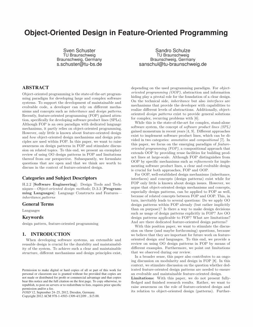
Object-Oriented Design in Feature-Oriented Programming
Sven SchusterTU Braunschweig
Braunschweig, [email protected]
Sandro SchulzeTU Braunschweig
Braunschweig, [email protected]
ABSTRACTObject-oriented programming is the state-of-the-art program-ming paradigm for developing large and complex softwaresystems. To support the development of maintainable andevolvable code, a developer can rely on different mecha-nisms and concepts such as inheritance and design patterns.Recently, feature-oriented programming (FOP) gained atten-tion, specifically for developing software product lines (SPLs).Although FOP is an own paradigm with dedicated languagemechanisms, it partly relies on object-oriented programming.However, only little is known about feature-oriented designand how object-oriented design mechanisms and design prin-ciples are used within FOP. In this paper, we want to raiseawareness on design patterns in FOP and stimulate discus-sion on related topics. To this end, we present an exemplaryreview of using OO design patterns in FOP and limitationsthereof from our perspective. Subsequently, we formulatequestions that are open and that we think are worth todiscuss in the context of feature-oriented design.
Categories and Subject DescriptorsH.2.2 [Software Engineering]: Design Tools and Tech-niques—Object-oriented design methods; D.3.3 [Program-ming Languages]: Language Constructs and Features—inheritance,patterns
General TermsLanguages
Keywordsdesign pattern, feature-oriented programming
1. INTRODUCTIONWhen developing software systems, an extensible and
reusable design is crucial for the durability and maintainabil-ity of the system. To achieve such a clear and maintainablestructure, different mechanisms and design principles exist,
Permission to make digital or hard copies of all or part of this work forpersonal or classroom use is granted without fee provided that copies arenot made or distributed for profit or commercial advantage and that copiesbear this notice and the full citation on the first page. To copy otherwise, torepublish, to post on servers or to redistribute to lists, requires prior specificpermission and/or a fee.FOSD’12, September 24–25, 2012, Dresden, Germany.Copyright 2012 ACM 978-1-4503-1309-4/12/09 ...$15.00.
depending on the used programming paradigm. For object-oriented programming (OOP), abstraction and informationhiding play a pivotal role for the foundation of a clear design.On the technical side, inheritance but also interfaces aremechanisms that provide the developer with capabilities torealize different levels of abstractions. Additionally, object-oriented design patterns exist to provide general solutionsfor complex, recurring problems with [6].
While this is the state-of-the-art for complex, stand-alonesoftware system, the concept of software product lines (SPL)gained momentum in recent years [4, 9]. Different approachesexist to implement software product lines, which can be di-vided in two categories: annotative and compositional [7]. Inthis paper, we focus on the emerging paradigm of feature-oriented programming (FOP), a compositional approach thatextends OOP by providing reuse facilities for building prod-uct lines at large-scale. Although FOP distinguishes fromOOP by specific mechanisms such as refinements for imple-menting software product lines, a clear and evolvable designis crucial for both approaches, FOP and OOP.
For OOP, well-established design mechanisms (inheritance,interfaces) and concepts (design patterns) exist while forFOP only little is known about design issues. However, weargue that object-oriented design mechanisms and concepts,especially design patterns, can be applied to FOP as well,because of related concepts between FOP and OOP. This, inturn, inevitably leads to several questions: Do we apply OOdesign patterns within FOP already (but rather implicitlythan on purpose)? Is there a way to make design decisionssuch as usage of design patterns explicitly in FOP? Are OOdesign patterns applicable to FOP? What are limitations?And are there dedicated feature-oriented design patterns?
With this position paper, we want to stimulate the discus-sion on these (and maybe forthcoming) questions, becausewe believe that they are important for future work on feature-oriented design and languages. To this end, we provide areview on using OO design patterns in FOP by means ofdifferent examples. Furthermore, we point out limitationsthat we observed during our review.
In a broader sense, this paper also contributes to an ongo-ing discussion on modularity and design in FOP [8]. In thiscontext, we stimulate discussion on the question whether ded-icated feature-oriented design patterns are needed to ensurean evolvable and maintainable feature-oriented design.Limitations: With this paper, we do not present fully-fledged and finished research results. Rather, we want toraise awareness on the role of feature-oriented design andits relation to object-oriented design (patterns). Further-
25
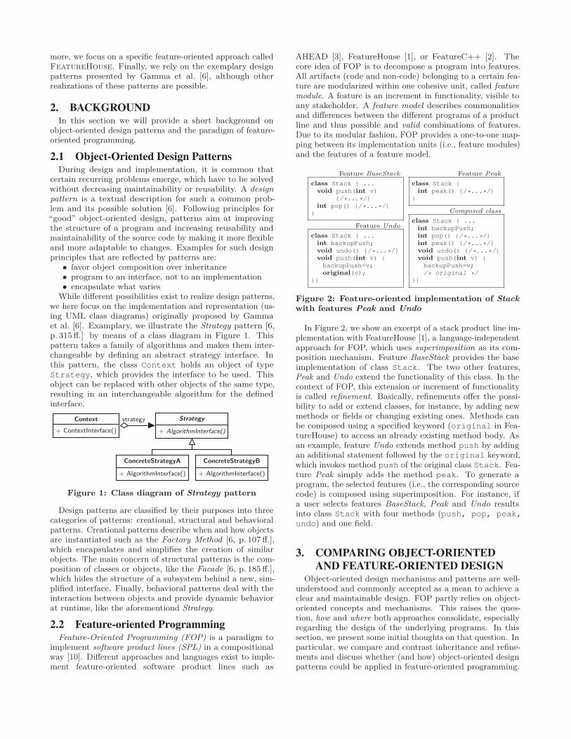
more, we focus on a specific feature-oriented approach calledFeatureHouse. Finally, we rely on the exemplary designpatterns presented by Gamma et al. [6], although otherrealizations of these patterns are possible.
2. BACKGROUNDIn this section we will provide a short background on
object-oriented design patterns and the paradigm of feature-oriented programming.
2.1 Object-Oriented Design PatternsDuring design and implementation, it is common that
certain recurring problems emerge, which have to be solvedwithout decreasing maintainability or reusability. A designpattern is a textual description for such a common prob-lem and its possible solution [6]. Following principles for“good” object-oriented design, patterns aim at improvingthe structure of a program and increasing reusability andmaintainability of the source code by making it more flexibleand more adaptable to changes. Examples for such designprinciples that are reflected by patterns are:
• favor object composition over inheritance• program to an interface, not to an implementation• encapsulate what varies
While different possibilities exist to realize design patterns,we here focus on the implementation and representation (us-ing UML class diagrams) originally proposed by Gammaet al. [6]. Examplary, we illustrate the Strategy pattern [6,p. 315 ff.] by means of a class diagram in Figure 1. Thispattern takes a family of algorithms and makes them inter-changeable by defining an abstract strategy interface. Inthis pattern, the class Context holds an object of typeStrategy, which provides the interface to be used. Thisobject can be replaced with other objects of the same type,resulting in an interchangeable algorithm for the definedinterface.
Context+ ContextInterface()
strategy Strategy
+ AlgorithmInterface()
ConcreteStrategyA
+ AlgorithmInterface()
ConcreteStrategyB
+ AlgorithmInterface()
Figure 1: Class diagram of Strategy pattern
Design patterns are classified by their purposes into threecategories of patterns: creational, structural and behavioralpatterns. Creational patterns describe when and how objectsare instantiated such as the Factory Method [6, p. 107 ff.],which encapsulates and simplifies the creation of similarobjects. The main concern of structural patterns is the com-position of classes or objects, like the Facade [6, p. 185 ff.],which hides the structure of a subsystem behind a new, sim-plified interface. Finally, behavioral patterns deal with theinteraction between objects and provide dynamic behaviorat runtime, like the aforementiond Strategy.
2.2 Feature-oriented ProgrammingFeature-Oriented Programming (FOP) is a paradigm to
implement software product lines (SPL) in a compositionalway [10]. Different approaches and languages exist to imple-ment feature-oriented software product lines such as
AHEAD [3], FeatureHouse [1], or FeatureC++ [2]. Thecore idea of FOP is to decompose a program into features.All artifacts (code and non-code) belonging to a certain fea-ture are modularized within one cohesive unit, called featuremodule. A feature is an increment in functionality, visible toany stakeholder. A feature model describes commonalitiesand differences between the different programs of a productline and thus possible and valid combinations of features.Due to its modular fashion, FOP provides a one-to-one map-ping between its implementation units (i.e., feature modules)and the features of a feature model.
Feature BaseStackclass Stack { ...
void push(int v){/*...*/}
int pop() {/*...*/}}
Feature Undoclass Stack { ...
int backupPush;void undo() {/*...*/}void push(int v) {backupPush=v;original(v);
}}
Feature Peakclass Stack {
int peak() {/*...*/}}
Composed classclass Stack { ...
int backupPush;int pop() {/*...*/}int peak() {/*...*/}void undo() {/*...*/}void push(int v) {backupPush=v;/* original */
}}
Figure 2: Feature-oriented implementation of Stackwith features Peak and Undo
In Figure 2, we show an excerpt of a stack product line im-plementation with FeatureHouse [1], a language-independentapproach for FOP, which uses superimposition as its com-position mechanism. Feature BaseStack provides the baseimplementation of class Stack. The two other features,Peak and Undo extend the functionality of this class. In thecontext of FOP, this extension or increment of functionalityis called refinement. Basically, refinements offer the possi-bility to add or extend classes, for instance, by adding newmethods or fields or changing existing ones. Methods canbe composed using a specified keyword (original in Fea-tureHouse) to access an already existing method body. Asan example, feature Undo extends method push by addingan additional statement followed by the original keyword,which invokes method push of the original class Stack. Fea-ture Peak simply adds the method peak. To generate aprogram, the selected features (i.e., the corresponding sourcecode) is composed using superimposition. For instance, ifa user selects features BaseStack, Peak and Undo resultsinto class Stack with four methods (push, pop, peak,undo) and one field.
3. COMPARING OBJECT-ORIENTEDAND FEATURE-ORIENTED DESIGN
Object-oriented design mechanisms and patterns are well-understood and commonly accepted as a mean to achieve aclear and maintainable design. FOP partly relies on object-oriented concepts and mechanisms. This raises the ques-tion, how and where both approaches consolidate, especiallyregarding the design of the underlying programs. In thissection, we present some initial thoughts on that question. Inparticular, we compare and contrast inheritance and refine-ments and discuss whether (and how) object-oriented designpatterns could be applied in feature-oriented programming.
26
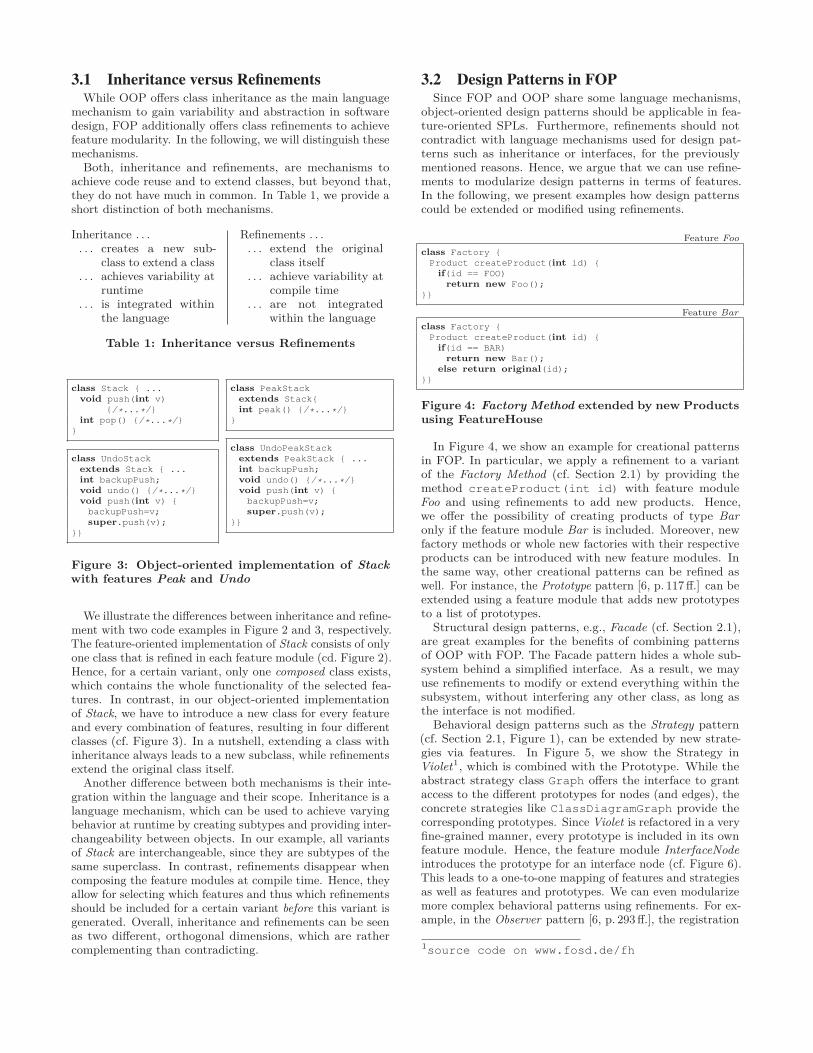
3.1 Inheritance versus RefinementsWhile OOP offers class inheritance as the main language
mechanism to gain variability and abstraction in softwaredesign, FOP additionally offers class refinements to achievefeature modularity. In the following, we will distinguish thesemechanisms.
Both, inheritance and refinements, are mechanisms toachieve code reuse and to extend classes, but beyond that,they do not have much in common. In Table 1, we provide ashort distinction of both mechanisms.
Inheritance . . .. . . creates a new sub-
class to extend a class. . . achieves variability at
runtime. . . is integrated within
the language
Refinements . . .. . . extend the original
class itself. . . achieve variability at
compile time. . . are not integrated
within the language
Table 1: Inheritance versus Refinements
class Stack { ...void push(int v)
{/*...*/}int pop() {/*...*/}
}
class UndoStackextends Stack { ...int backupPush;void undo() {/*...*/}void push(int v) {backupPush=v;super.push(v);
}}
class PeakStackextends Stack{int peak() {/*...*/}
}
class UndoPeakStackextends PeakStack { ...int backupPush;void undo() {/*...*/}void push(int v) {backupPush=v;super.push(v);
}}
Figure 3: Object-oriented implementation of Stackwith features Peak and Undo
We illustrate the differences between inheritance and refine-ment with two code examples in Figure 2 and 3, respectively.The feature-oriented implementation of Stack consists of onlyone class that is refined in each feature module (cd. Figure 2).Hence, for a certain variant, only one composed class exists,which contains the whole functionality of the selected fea-tures. In contrast, in our object-oriented implementationof Stack, we have to introduce a new class for every featureand every combination of features, resulting in four differentclasses (cf. Figure 3). In a nutshell, extending a class withinheritance always leads to a new subclass, while refinementsextend the original class itself.
Another difference between both mechanisms is their inte-gration within the language and their scope. Inheritance is alanguage mechanism, which can be used to achieve varyingbehavior at runtime by creating subtypes and providing inter-changeability between objects. In our example, all variantsof Stack are interchangeable, since they are subtypes of thesame superclass. In contrast, refinements disappear whencomposing the feature modules at compile time. Hence, theyallow for selecting which features and thus which refinementsshould be included for a certain variant before this variant isgenerated. Overall, inheritance and refinements can be seenas two different, orthogonal dimensions, which are rathercomplementing than contradicting.
3.2 Design Patterns in FOPSince FOP and OOP share some language mechanisms,
object-oriented design patterns should be applicable in fea-ture-oriented SPLs. Furthermore, refinements should notcontradict with language mechanisms used for design pat-terns such as inheritance or interfaces, for the previouslymentioned reasons. Hence, we argue that we can use refine-ments to modularize design patterns in terms of features.In the following, we present examples how design patternscould be extended or modified using refinements.
Feature Fooclass Factory {Product createProduct(int id) {
if(id == FOO)return new Foo();
}}
Feature Barclass Factory {Product createProduct(int id) {
if(id == BAR)return new Bar();
else return original(id);}}
Figure 4: Factory Method extended by new Productsusing FeatureHouse
In Figure 4, we show an example for creational patternsin FOP. In particular, we apply a refinement to a variantof the Factory Method (cf. Section 2.1) by providing themethod createProduct(int id) with feature moduleFoo and using refinements to add new products. Hence,we offer the possibility of creating products of type Baronly if the feature module Bar is included. Moreover, newfactory methods or whole new factories with their respectiveproducts can be introduced with new feature modules. Inthe same way, other creational patterns can be refined aswell. For instance, the Prototype pattern [6, p. 117 ff.] can beextended using a feature module that adds new prototypesto a list of prototypes.
Structural design patterns, e.g., Facade (cf. Section 2.1),are great examples for the benefits of combining patternsof OOP with FOP. The Facade pattern hides a whole sub-system behind a simplified interface. As a result, we mayuse refinements to modify or extend everything within thesubsystem, without interfering any other class, as long asthe interface is not modified.
Behavioral design patterns such as the Strategy pattern(cf. Section 2.1, Figure 1), can be extended by new strate-gies via features. In Figure 5, we show the Strategy inViolet1, which is combined with the Prototype. While theabstract strategy class Graph offers the interface to grantaccess to the different prototypes for nodes (and edges), theconcrete strategies like ClassDiagramGraph provide thecorresponding prototypes. Since Violet is refactored in a veryfine-grained manner, every prototype is included in its ownfeature module. Hence, the feature module InterfaceNodeintroduces the prototype for an interface node (cf. Figure 6).This leads to a one-to-one mapping of features and strategiesas well as features and prototypes. We can even modularizemore complex behavioral patterns using refinements. For ex-ample, in the Observer pattern [6, p. 293 ff.], the registration
1source code on www.fosd.de/fh
27
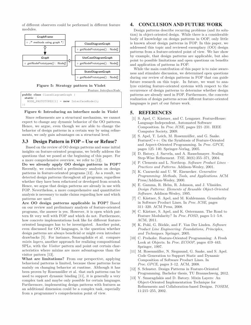
of different observers could be performed in different featuremodules.
GraphFrame
+ /* methods using graph */
Graph
+ getNodePrototypes() : Node[]
ClassDiagramGraph
+ getNodePrototypes() : Node[]
UseCaseDiagramGraph
+ getNodePrototypes() : Node[]
StateDiagramGraph
+ getNodePrototypes() : Node[]
Figure 5: Strategy pattern in VioletFeature InterfaceNode
public class ClassDiagramGraph {static {NODE_PROTOTYPES[1] = new InterfaceNode();
}}
Figure 6: Introducing an interface node in VioletSince refinements are a structural mechanism, we cannot
expect to change any dynamic behavior of the OO patterns.Hence, we argue, even though we are able to change thebehavior of design patterns in a certain way by using refine-ments, we only gain advantages on a structural level.
3.3 Design Pattern in FOP – Use or Refuse?Based on the review of OO design patterns and some initial
insights on feature-oriented programs, we briefly address thequestions that we posed at the beginning of this paper. Fora more comprehensive overview, we refer to [12].Do we already apply OO design patterns in FOP?Recently, we conducted a preliminary analysis on designpatterns in feature-oriented programs [12]. As a result, wedetected design patterns throughout all programs, regardlesswhether they have been refactored or developed from scratch.Hence, we argue that design patterns are already in use withFOP. Nevertheless, a more comprehensive and quantitativeanalysis is necessary to make claims regarding how and whichpatterns are used.Are OO design patterns applicable in FOP? Basedon our review and preliminary analysis of feature-orientedprograms, the answer is yes. However, it is open which pat-tern fit very well with FOP and which do not. Furthermore,how concrete implementations look like for different feature-oriented languages has to be investigated. Another point,even discussed for OO languages, is the question whetherdesign patterns are always beneficial or might even introducedrawbacks [5]. For instance, Smaragdakis et al. comparemixin layers, another approach for realizing compositionalSPLs, with the Visitor pattern and point out certain char-acteristics where mixins are more advantageous than thevisitor pattern [13].What are limitations? From our perspective, applyingbehavioral patterns is limited, because these patterns focusmainly on changing behavior at runtime. Although it hasbeen proven by Rosenmüller et al. that such patterns can beused to support dynamic binding [11], it is generally a verycomplex task and maybe only possible for certain languages.Furthermore, implementing design patterns with features asan additional dimension could be a complex task, especiallyfrom a programmer’s comprehension point of view.
4. CONCLUSION AND FUTURE WORKDesign patterns describe recurring problems (and its solu-
tion) in object-oriented design. While there is a considerablebody of knowledge on design patterns in OOP, only littleis known about design patterns in FOP. In this paper, weaddressed this topic and reviewed exemplary (OO) designpatterns from a feature-oriented point of view. We hav showby example, that design patterns are applicable, but alsopoint to possible limitations and open questions on benefitsand application of patterns in FOP.
While the main contribution of this paper is to raise aware-ness and stimulate discussion, we determined open questionsduring our review of design patterns in FOP that can guidefuture research on this topic. In future, we want to ana-lyze existing feature-oriented systems with respect to theoccurrence of design patterns to determine whether designpatterns are already used in FOP. Furthermore, the concreterealization of design patterns across different feature-orientedlanguages is part of our future work.
5. REFERENCES[1] S. Apel, C. Kästner, and C. Lengauer. FeatureHouse:
Language-Independent, Automated SoftwareComposition. In Proc. ICSE, pages 221–231. IEEEComputer Society, 2009.
[2] S. Apel, T. Leich, M. Rosenmüller, and G. Saake.FeatureC++: On the Symbiosis of Feature-Orientedand Aspect-Oriented Programming. In Proc. GPCE,pages 125–140. Springer-Verlag, 2005.
[3] D. Batory, J. Sarvela, and A. Rauschmayer. ScalingStep-Wise Refinement. TSE, 30(6):355–371, 2004.
[4] P. Clements and L. Northrop. Software Product Lines –Practices and Patterns. Addison-Wesley, 2001.
[5] K. Czarnecki and U. W. Eisenecker. GenerativeProgramming: Methods, Tools, and Applications. ACMPress/Addison-Wesley, 2000.
[6] E. Gamma, R. Helm, R. Johnson, and J. Vlissides.Design Patterns: Elements of Reusable Object-OrientedSoftware. Addison-Wesley, 1995.
[7] C. Kästner, S. Apel, and M. Kuhlemann. Granularityin Software Product Lines. In Proc. ICSE, pages311–320. ACM Press, 2008.
[8] C. Kästner, S. Apel, and K. Ostermann. The Road toFeature Modularity? In Proc. FOSD, pages 5:1–5:8.ACM, 2011.
[9] K. Pohl, G. Böckle, and F. Van Der Linden. SoftwareProduct Line Engineering: Foundations, Principles,and Techniques. Springer, 2005.
[10] C. Prehofer. Feature-Oriented Programming: A FreshLook at Objects. In Proc. ECOOP, pages 419–443.Springer, 1997.
[11] M. Rosenmüller, N. Siegmund, G. Saake, and S. Apel.Code Generation to Support Static and DynamicComposition of Software Product Lines. InProc. GPCE, pages 3–12. ACM, 2008.
[12] S. Schuster. Design Patterns in Feature-OrientedProgramming. Bachelor thesis, TU Braunschweig, 2012.
[13] Y. Smaragdakis and D. Batory. Mixin Layers: AnObject-Oriented Implementation Technique forRefinements and Collaboration-based Designs. TOSEM,11:215–255, 2002.
28
Architectural Variability Management in Multi-Layer WebApplications Through Feature Models
Jose Garcia-AlonsoCentro Universitario de MeridaUniversidad de Extremadura
Avda. Santa Teresa de Jornet,38
Merida, [email protected]
Javier Berrocal OlmedaEscuela Politecnica
Universidad de ExtremaduraAvda. de la Universidad, s/n
Caceres, [email protected]
Juan Manuel MurilloEscuela Politecnica
Universidad de ExtremaduraAvda. de la Universidad, s/n
Caceres, [email protected]
ABSTRACTThe development of large web applications has focused onthe use of increasingly complex architectures based on thelayer architectural pattern and different development frame-works. Many techniques have been proposed to deal withthis increasing complexity, mostly in the field of model-baseddevelopment which abstracts the architects and designersfrom the architectural and technological complexities. How-ever, these techniques do not take into account the greatvariability of these architectures, and therefore limit the ar-chitectural options available for their users. We here de-scribe a feature model that captures the architectural andtechnological variability of multilayer applications. Usingthis feature model as the core of a model-driven develop-ment process, we are able to incorporate architectural andtechnological variability into the model-based developmentof multilayer applications. This approach keeps complexityunder control whilst flexibility on choosing technologies isnot penalized
Categories and Subject DescriptorsD.2.11 [Software Engineering]: Software Architectures;D.2.13 [Software Engineering]: Reusable Software
General TermsDesign
KeywordsMultilayer architectures, feature model, design patterns, de-velopment frameworks, model-driven development
1. INTRODUCTIONAdvances in technology as well as in the use of Internet
by the general population have led to ever more advanced
Permission to make digital or hard copies of all or part of this work forpersonal or classroom use is granted without fee provided that copies arenot made or distributed for profit or commercial advantage and that copiesbear this notice and the full citation on the first page. To copy otherwise, torepublish, to post on servers or to redistribute to lists, requires prior specificpermission and/or a fee.FOSD’12 September 24-25, 2012, Dresden, GermanyCopyright 2012 ACM 978-1-4503-1309-4/12/09 ...$15.00.
Web applications being built. The increased complexity ofthese applications naturally involves greater complexity intheir development. One of the principal tools that softwareengineers have when confronting a complex development isrepresented by design patterns [11] – reusable general solu-tions for common problems in a given context.
In the context of Web applications, one of the commonestarchitectural patterns is the layer pattern [5]. This patternproposes subdividing a system into a set of layers, each ofwhich provides services to the layer above and consumes ser-vices from the layer below. Based on this principle, complexmultilayer architectures can be developed in the way that agiven layer can provide services to several upper-level layers.For instance, a business logic layer can provide services to auser interface layer and a Web service layer, or a single layercan be located transversally, and thus provide services to allthe other layers, an example being a log layer.
Using the layer architectural pattern, the development isdivided into several layers of a lower order of complexitythan that of the complete system. The development of eachof these layers presents its own challenges, however, so thatit is usual to go back to using other design patterns. Inorder to facilitate the use of those design patterns, develop-ment frameworks have become especially relevant. This isreflected in the large number of existing frameworks [25], thetraffic generated by their mailing lists, and the number of joboffers requesting experience in their use [23]. These frame-works ”provide domain-specific concepts, which are genericunits of functionality. Developers create framework-basedapplications by writing framework completion code, whichinstantiates these concepts” [3].
The use of the layer architectural pattern combined withspecific development frameworks for each of the layers in theapplication provides greater quality in terms of reliabilityand maintainability [5]. But it also introduces new prob-lems [14]. Everyone involved in building such an applicationmust have in-depth technical knowledge in the use of thechosen frameworks. Frameworks are advanced tools whoseuse requires highly trained personnel. This problem can bemitigated using model-driven development techniques thatabstract developers from the technical details of the tech-nology [24].
However, current solutions are not fully optimal due toits limitations [16]. In an environment with many rapidlyevolving technologies, model-driven techniques need contin-ual updates to keep pace with technological advances. These
29
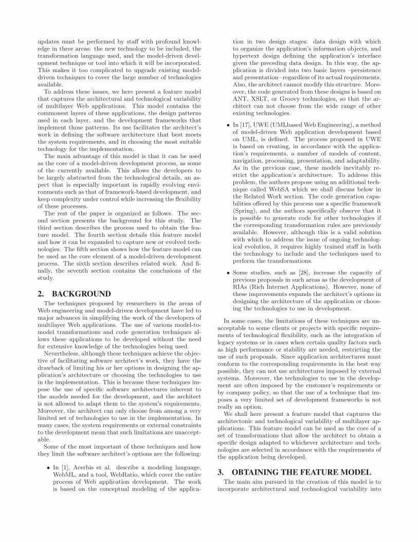
updates must be performed by staff with profound knowl-edge in three areas: the new technology to be included, thetransformation language used, and the model-driven devel-opment technique or tool into which it will be incorporated.This makes it too complicated to upgrade existing model-driven techniques to cover the large number of technologiesavailable.
To address these issues, we here present a feature modelthat captures the architectural and technological variabilityof multilayer Web applications. This model contains thecommonest layers of these applications, the design patternsused in each layer, and the development frameworks thatimplement those patterns. Its use facilitates the architect’swork in defining the software architecture that best meetsthe system requirements, and in choosing the most suitabletechnology for the implementation.
The main advantage of this model is that it can be usedas the core of a model-driven development process, as someof the currently available. This allows the developers tobe largely abstracted from the technological details, an as-pect that is especially important in rapidly evolving envi-ronments such as that of framework-based development, andkeep complexity under control while increasing the flexibilityof these processes.
The rest of the paper is organized as follows. The sec-ond section presents the background for this study. Thethird section describes the process used to obtain the fea-ture model. The fourth section details this feature modeland how it can be expanded to capture new or evolved tech-nologies. The fifth section shows how the feature model canbe used as the core element of a model-driven developmentprocess. The sixth section describes related work. And fi-nally, the seventh section contains the conclusions of thestudy.
2. BACKGROUNDThe techniques proposed by researchers in the areas of
Web engineering and model-driven development have led tomajor advances in simplifying the work of the developers ofmultilayer Web applications. The use of various model-to-model transformations and code generation techniques al-lows these applications to be developed without the needfor extensive knowledge of the technologies being used.
Nevertheless, although these techniques achieve the objec-tive of facilitating software architect’s work, they have thedrawback of limiting his or her options in designing the ap-plication’s architecture or choosing the technologies to usein the implementation. This is because these techniques im-pose the use of specific software architectures inherent tothe models needed for the development, and the architectis not allowed to adapt them to the system’s requirements.Moreover, the architect can only choose from among a verylimited set of technologies to use in the implementation. Inmany cases, the system requirements or external constraintsto the development mean that such limitations are unaccept-able.
Some of the most important of these techniques and howthey limit the software architect’s options are the following:
• In [1], Acerbis et al. describe a modeling language,WebML, and a tool, WebRatio, which cover the entireprocess of Web application development. The workis based on the conceptual modeling of the applica-
tion in two design stages: data design with whichto organize the application’s information objects, andhypertext design defining the application’s interfacegiven the preceding data design. In this way, the ap-plication is divided into two basic layers –persistenceand presentation– regardless of its actual requirements.Also, the architect cannot modify this structure. More-over, the code generated from these designs is based onANT, XSLT, or Groovy technologies, so that the ar-chitect can not choose from the wide range of otherexisting technologies.
• In [17], UWE (UMLbasedWeb Engineering), a methodof model-driven Web application development basedon UML, is defined. The process proposed in UWEis based on creating, in accordance with the applica-tion’s requirements, a number of models of content,navigation, processing, presentation, and adaptability.As in the previous case, these models inevitably re-strict the application’s architecture. To address thisproblem, the authors propose using an additional tech-nique called WebSA which we shall discuss below inthe Related Work section. The code generation capa-bilities offered by this process use a specific framework(Spring), and the authors specifically observe that itis possible to generate code for other technologies ifthe corresponding transformation rules are previouslyavailable. However, although this is a valid solutionwith which to address the issue of ongoing technolog-ical evolution, it requires highly trained staff in boththe technology to include and the techniques used toperform the transformations.
• Some studies, such as [28], increase the capacity ofprevious proposals in such areas as the development ofRIAs (Rich Internet Applications). However, none ofthese improvements expands the architect’s options indesigning the architecture of the application or choos-ing the technologies to use in development.
In some cases, the limitations of these techniques are un-acceptable to some clients or projects with specific require-ments of technological flexibility, such as the integration oflegacy systems or in cases when certain quality factors suchas high performance or stability are needed, restricting theuse of such proposals. Since application architectures mustconform to the corresponding requirements in the best waypossible, they can not use architectures imposed by externalsystems. Moreover, the technologies to use in the develop-ment are often imposed by the customer’s requirements orby company policy, so that the use of a technique that im-poses a very limited set of development frameworks is notreally an option.
We shall here present a feature model that captures thearchitectonic and technological variability of multilayer ap-plications. This feature model can be used as the core of aset of transformations that allow the architect to obtain aspecific design adapted to whichever architecture and tech-nologies are selected in accordance with the requirements ofthe application being developed.
3. OBTAINING THE FEATURE MODELThe main aim pursued in the creation of this model is to
incorporate architectural and technological variability into
30
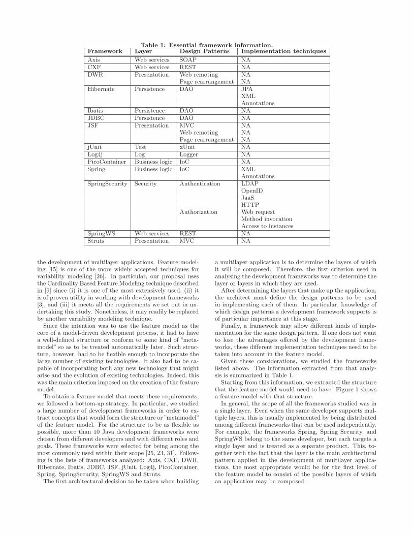
Table 1: Essential framework information.Framework Layer Design Patterns Implementation techniques
Axis Web services SOAP NACXF Web services REST NADWR Presentation Web remoting NA
Page rearrangement NAHibernate Persistence DAO JPA
XMLAnnotations
Ibatis Persistence DAO NAJDBC Persistence DAO NAJSF Presentation MVC NA
Web remoting NAPage rearrangement NA
jUnit Test xUnit NALog4j Log Logger NAPicoContainer Business logic IoC NASpring Business logic IoC XML
AnnotationsSpringSecurity Security Authentication LDAP
OpenIDJaaSHTTP
Authorization Web requestMethod invocationAccess to instances
SpringWS Web services REST NAStruts Presentation MVC NA
the development of multilayer applications. Feature model-ing [15] is one of the more widely accepted techniques forvariability modeling [26]. In particular, our proposal usesthe Cardinality Based Feature Modeling technique describedin [9] since (i) it is one of the most extensively used, (ii) itis of proven utility in working with development frameworks[3], and (iii) it meets all the requirements we set out in un-dertaking this study. Nonetheless, it may readily be replacedby another variability modeling technique.
Since the intention was to use the feature model as thecore of a model-driven development process, it had to havea well-defined structure or conform to some kind of ”meta-model” so as to be treated automatically later. Such struc-ture, however, had to be flexible enough to incorporate thelarge number of existing technologies. It also had to be ca-pable of incorporating both any new technology that mightarise and the evolution of existing technologies. Indeed, thiswas the main criterion imposed on the creation of the featuremodel.
To obtain a feature model that meets these requirements,we followed a bottom-up strategy. In particular, we studieda large number of development frameworks in order to ex-tract concepts that would form the structure or ”metamodel”of the feature model. For the structure to be as flexible aspossible, more than 10 Java development frameworks werechosen from different developers and with different roles andgoals. These frameworks were selected for being among themost commonly used within their scope [25, 23, 31]. Follow-ing is the lists of frameworks analysed: Axis, CXF, DWR,Hibernate, Ibatis, JDBC, JSF, jUnit, Log4j, PicoContainer,Spring, SpringSecurity, SpringWS and Struts.
The first architectural decision to be taken when building
a multilayer application is to determine the layers of whichit will be composed. Therefore, the first criterion used inanalysing the development frameworks was to determine thelayer or layers in which they are used.
After determining the layers that make up the application,the architect must define the design patterns to be usedin implementing each of them. In particular, knowledge ofwhich design patterns a development framework supports isof particular importance at this stage.
Finally, a framework may allow different kinds of imple-mentation for the same design pattern. If one does not wantto lose the advantages offered by the development frame-works, these different implementation techniques need to betaken into account in the feature model.
Given these considerations, we studied the frameworkslisted above. The information extracted from that analy-sis is summarized in Table 1.
Starting from this information, we extracted the structurethat the feature model would need to have. Figure 1 showsa feature model with that structure.
In general, the scope of all the frameworks studied was ina single layer. Even when the same developer supports mul-tiple layers, this is usually implemented by being distributedamong different frameworks that can be used independently.For example, the frameworks Spring, Spring Security, andSpringWS belong to the same developer, but each targets asingle layer and is treated as a separate product. This, to-gether with the fact that the layer is the main architecturalpattern applied in the development of multilayer applica-tions, the most appropriate would be for the first level ofthe feature model to consist of the possible layers of whichan application may be composed.
31
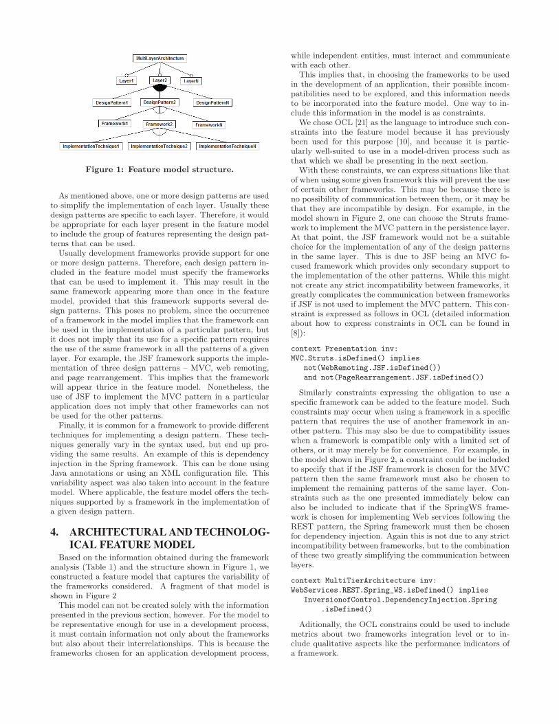
Figure 1: Feature model structure.
As mentioned above, one or more design patterns are usedto simplify the implementation of each layer. Usually thesedesign patterns are specific to each layer. Therefore, it wouldbe appropriate for each layer present in the feature modelto include the group of features representing the design pat-terns that can be used.
Usually development frameworks provide support for oneor more design patterns. Therefore, each design pattern in-cluded in the feature model must specify the frameworksthat can be used to implement it. This may result in thesame framework appearing more than once in the featuremodel, provided that this framework supports several de-sign patterns. This poses no problem, since the occurrenceof a framework in the model implies that the framework canbe used in the implementation of a particular pattern, butit does not imply that its use for a specific pattern requiresthe use of the same framework in all the patterns of a givenlayer. For example, the JSF framework supports the imple-mentation of three design patterns – MVC, web remoting,and page rearrangement. This implies that the frameworkwill appear thrice in the feature model. Nonetheless, theuse of JSF to implement the MVC pattern in a particularapplication does not imply that other frameworks can notbe used for the other patterns.
Finally, it is common for a framework to provide differenttechniques for implementing a design pattern. These tech-niques generally vary in the syntax used, but end up pro-viding the same results. An example of this is dependencyinjection in the Spring framework. This can be done usingJava annotations or using an XML configuration file. Thisvariability aspect was also taken into account in the featuremodel. Where applicable, the feature model offers the tech-niques supported by a framework in the implementation ofa given design pattern.
4. ARCHITECTURAL AND TECHNOLOG-ICAL FEATURE MODEL
Based on the information obtained during the frameworkanalysis (Table 1) and the structure shown in Figure 1, weconstructed a feature model that captures the variability ofthe frameworks considered. A fragment of that model isshown in Figure 2
This model can not be created solely with the informationpresented in the previous section, however. For the model tobe representative enough for use in a development process,it must contain information not only about the frameworksbut also about their interrelationships. This is because theframeworks chosen for an application development process,
while independent entities, must interact and communicatewith each other.
This implies that, in choosing the frameworks to be usedin the development of an application, their possible incom-patibilities need to be explored, and this information needsto be incorporated into the feature model. One way to in-clude this information in the model is as constraints.
We chose OCL [21] as the language to introduce such con-straints into the feature model because it has previouslybeen used for this purpose [10], and because it is partic-ularly well-suited to use in a model-driven process such asthat which we shall be presenting in the next section.
With these constraints, we can express situations like thatof when using some given framework this will prevent the useof certain other frameworks. This may be because there isno possibility of communication between them, or it may bethat they are incompatible by design. For example, in themodel shown in Figure 2, one can choose the Struts frame-work to implement the MVC pattern in the persistence layer.At that point, the JSF framework would not be a suitablechoice for the implementation of any of the design patternsin the same layer. This is due to JSF being an MVC fo-cused framework which provides only secondary support tothe implementation of the other patterns. While this mightnot create any strict incompatibility between frameworks, itgreatly complicates the communication between frameworksif JSF is not used to implement the MVC pattern. This con-straint is expressed as follows in OCL (detailed informationabout how to express constraints in OCL can be found in[8]):
context Presentation inv:
MVC.Struts.isDefined() implies
not(WebRemoting.JSF.isDefined())
and not(PageRearrangement.JSF.isDefined())
Similarly constraints expressing the obligation to use aspecific framework can be added to the feature model. Suchconstraints may occur when using a framework in a specificpattern that requires the use of another framework in an-other pattern. This may also be due to compatibility issueswhen a framework is compatible only with a limited set ofothers, or it may merely be for convenience. For example, inthe model shown in Figure 2, a constraint could be includedto specify that if the JSF framework is chosen for the MVCpattern then the same framework must also be chosen toimplement the remaining patterns of the same layer. Con-straints such as the one presented immediately below canalso be included to indicate that if the SpringWS frame-work is chosen for implementing Web services following theREST pattern, the Spring framework must then be chosenfor dependency injection. Again this is not due to any strictincompatibility between frameworks, but to the combinationof these two greatly simplifying the communication betweenlayers.
context MultiTierArchitecture inv:
WebServices.REST.Spring_WS.isDefined() implies
InversionofControl.DependencyInjection.Spring
.isDefined()
Aditionally, the OCL constrains could be used to includemetrics about two frameworks integration level or to in-clude qualitative aspects like the performance indicators ofa framework.
32
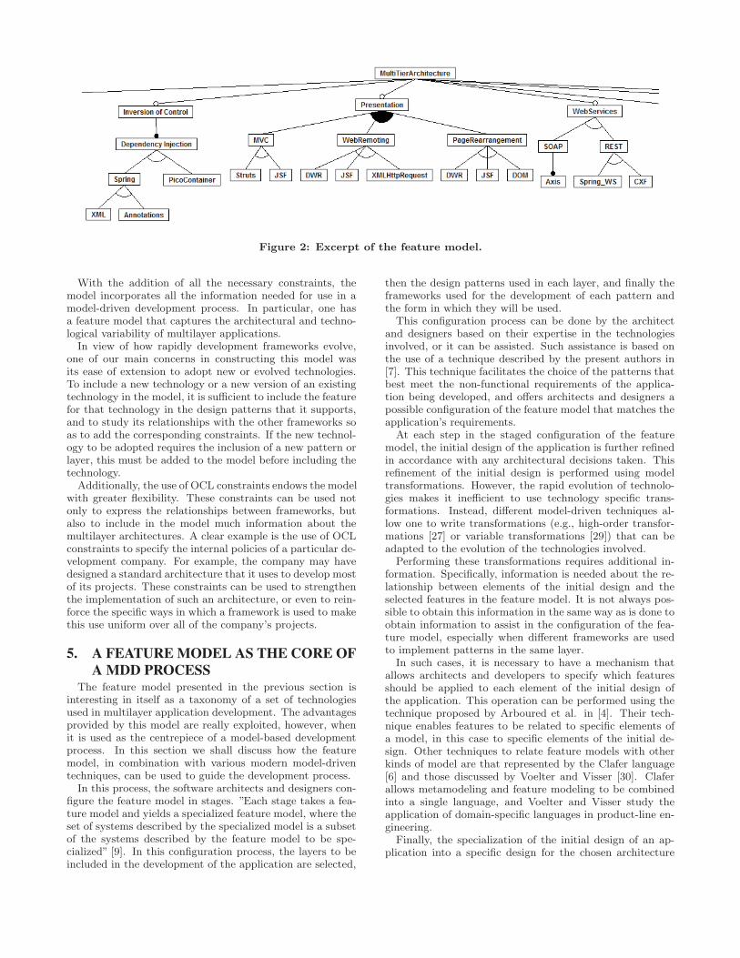
Figure 2: Excerpt of the feature model.
With the addition of all the necessary constraints, themodel incorporates all the information needed for use in amodel-driven development process. In particular, one hasa feature model that captures the architectural and techno-logical variability of multilayer applications.
In view of how rapidly development frameworks evolve,one of our main concerns in constructing this model wasits ease of extension to adopt new or evolved technologies.To include a new technology or a new version of an existingtechnology in the model, it is sufficient to include the featurefor that technology in the design patterns that it supports,and to study its relationships with the other frameworks soas to add the corresponding constraints. If the new technol-ogy to be adopted requires the inclusion of a new pattern orlayer, this must be added to the model before including thetechnology.
Additionally, the use of OCL constraints endows the modelwith greater flexibility. These constraints can be used notonly to express the relationships between frameworks, butalso to include in the model much information about themultilayer architectures. A clear example is the use of OCLconstraints to specify the internal policies of a particular de-velopment company. For example, the company may havedesigned a standard architecture that it uses to develop mostof its projects. These constraints can be used to strengthenthe implementation of such an architecture, or even to rein-force the specific ways in which a framework is used to makethis use uniform over all of the company’s projects.
5. A FEATURE MODEL AS THE CORE OFA MDD PROCESS
The feature model presented in the previous section isinteresting in itself as a taxonomy of a set of technologiesused in multilayer application development. The advantagesprovided by this model are really exploited, however, whenit is used as the centrepiece of a model-based developmentprocess. In this section we shall discuss how the featuremodel, in combination with various modern model-driventechniques, can be used to guide the development process.
In this process, the software architects and designers con-figure the feature model in stages. ”Each stage takes a fea-ture model and yields a specialized feature model, where theset of systems described by the specialized model is a subsetof the systems described by the feature model to be spe-cialized” [9]. In this configuration process, the layers to beincluded in the development of the application are selected,
then the design patterns used in each layer, and finally theframeworks used for the development of each pattern andthe form in which they will be used.
This configuration process can be done by the architectand designers based on their expertise in the technologiesinvolved, or it can be assisted. Such assistance is based onthe use of a technique described by the present authors in[7]. This technique facilitates the choice of the patterns thatbest meet the non-functional requirements of the applica-tion being developed, and offers architects and designers apossible configuration of the feature model that matches theapplication’s requirements.
At each step in the staged configuration of the featuremodel, the initial design of the application is further refinedin accordance with any architectural decisions taken. Thisrefinement of the initial design is performed using modeltransformations. However, the rapid evolution of technolo-gies makes it inefficient to use technology specific trans-formations. Instead, different model-driven techniques al-low one to write transformations (e.g., high-order transfor-mations [27] or variable transformations [29]) that can beadapted to the evolution of the technologies involved.
Performing these transformations requires additional in-formation. Specifically, information is needed about the re-lationship between elements of the initial design and theselected features in the feature model. It is not always pos-sible to obtain this information in the same way as is done toobtain information to assist in the configuration of the fea-ture model, especially when different frameworks are usedto implement patterns in the same layer.
In such cases, it is necessary to have a mechanism thatallows architects and developers to specify which featuresshould be applied to each element of the initial design ofthe application. This operation can be performed using thetechnique proposed by Arboured et al. in [4]. Their tech-nique enables features to be related to specific elements ofa model, in this case to specific elements of the initial de-sign. Other techniques to relate feature models with otherkinds of model are that represented by the Clafer language[6] and those discussed by Voelter and Visser [30]. Claferallows metamodeling and feature modeling to be combinedinto a single language, and Voelter and Visser study theapplication of domain-specific languages in product-line en-gineering.
Finally, the specialization of the initial design of an ap-plication into a specific design for the chosen architecture
33
and technologies is carried out, as mentioned above, usingmodel transformations. Feature models, however, are de-signed for use in product lines, and are not readily appliedto processes that involve model transformations specific tomodel-based development. In particular, the QVT language[22], the OMG standard for performing model transforma-tions, requires the two models involved in a transformationto be based on MOF metamodels, but feature models arenot based on a metamodel defined using this system.
Besides, these models would present another problem re-gardless of whether or not they were based on a metamodelsuitable for the realization of the transformations: the fea-ture model is not used just as it is, but different configu-rations of the model are also necessary. This increases thedifficulty of using these models in transformations becausethe configurations are at a lower level in the four-layer ar-chitecture of MOF.
These problems have been resolved by Gomez and Ramos[12]. They define a metamodel for modeling CBFM fea-ture models based on MOF. The model shown in Figure2 can thus be converted to a model based on their meta-model. Additionally, Gomez and Ramos provide a set ofQVT transformations that convert the feature model intoan MOF-based metamodel. This metamodel allows configu-rations of the feature model to be created at the appropriatelevel of MOF for their use in transformation processes. Afeature model based on MOF also facilitates the use of OCLconstraints such as those discussed in the previous section.
The combination of the feature model presented here withthe various techniques that have been mentioned in this sec-tion enables this model to be used as the core of a model-driven development process. This process simplifies the con-version of an initial design of the application (independentlyof which architecture and technologies are going to be usedin the implementation) into a specific design for the chosenarchitecture and technologies. A major advantage of thisprocess in an environment in which development frameworksevolve so rapidly is that it needs no in-depth knowledge ofthe technical operation of the frameworks.
6. RELATED WORKAs was noted above, there have been numerous works in
the area of model-driven development which deal with thedevelopment of enterprise applications that have complex ar-chitectures, and are implemented using development frame-works. This is especially so in Web engineering, with suchstudies as WebML [1], UWE [17], RUX [28], etc.
These studies all provide techniques with which to richlymodel the functionality of Web applications, and a set oftransformations that allow the user to generate the applica-tion’s code from those models. They do not, however, pro-vide much flexibility. In most cases, applications developedwith these techniques have a fixed architecture which can beneither influenced nor altered by the software architect, andwhich is often implicit in the models that are created. Forexample, most of these methods require both a persistencemodel and a presentation model, thus forcing the presenceof these layers in any application which is developed. Thecase is similar in the choice of technology. The use of thesemethods requires the adoption of technologies for which thetransformations provided in the method can generate theapplication’s code, thus further limiting the choices avail-able.
Nevertheless, in this same field of Web engineering therehave been proposals aimed at endowing the process of de-signing the application’s architecture with a certain flexibil-ity. Melia and Gomez [18] propose an extension of the meth-ods mentioned above which they call Web Software Archi-tecture (WebSA). This extension adds flexibility to the pre-vious methods by providing them with the means requiredto define the architecture used. Two models are added toachieve this goal: a subsystems model and a configurationmodel. These two models define the architectural features ofthe Web application that is to be developed. They are bothlinked to the functional models of the application (whichmay be constructed with any of the previous methods: OO-H, WebML, etc.), and are used to generate the applicationwith the desired architecture through a series of transforma-tions.
A more recent study by those same authors [19] describesa similar proposal aimed at the development of RIAs. In par-ticular, it proposes OOH4RIA as an OOH extension specif-ically designed for the development of RIAs. The authorsdescribe the use of a feature model, similar to the one used inthe present work, to define RIA features, and a componentmodel to explicitly represent the architecture of the RIA.Once again, these models are used together with the func-tional models of OOH to generate the application’s sourcecode.
These two works (especially the more recent) are closelyrelated to that presented here. They pursue the same goal:to enable developers who use model-driven techniques to in-fluence the architecture of their applications. However, themain focus of the works of Melia and Gomez is on RIA,whereas the work presented here is intended to provide sup-port for all applications that use a multilayer architecture.Also, in contrast with the technique presented here, theydo not allow developers to decide which technologies will beused for the development of the application.
In the field of framework-based software development, thestudies of Antkiewicz et al. [3] and Heydarnoori et al. [13]are of particular interest. Antkiewicz et al. propose tech-niques that allow framework-specific designs to be modeled,and these designs then to be used to generate the sourcecode. Heydarnoori et al. propose a technique to automati-cally extract framework concept-implementation templates.Unlike the work proposed here, these proposals are centredat a low level of abstraction, thus requiring their users topossess a deeper technical understanding of the frameworksthey want to use. The present work raises the level of ab-straction by starting from the design of the software archi-tecture.
Finally, some works in the architecture quality field haveproposed techniques to increase a system’s architectural vari-ability. In [20], Naab and Stamel propose a technique toachieve flexibility during the architecture design stage forthis flexibility to be exploitable during system evolution.This technique improves variability in the architecture, sothat it can be adapted to future evolution of the system,while the technique presented here is designed to provide asmuch variability as possible to the architect before construc-tion begins. In [2], Alebrahim and Heisel present a UML-based approach to modeling variability in architectures byadopting the notion of feature modeling. In their proposal,the variability is that introduced into an architecture byquality attributes, to take into account how they affect the
34
final architecture. In our proposal, quality attributes areused (as described in [7]) to guide the configuration processof the architectural feature model.
To the best of the authors’ knowledge, there has beenno previous work on using product lines and model-drivendevelopment techniques to increase the options of softwarearchitects in the work of selecting which design patterns anddevelopment frameworks to use in the development of a mul-tilayer application.
7. CONCLUSIONSWe have presented a feature model that captures the ar-
chitectural and technological variability of multilayer ap-plications. This model was obtained from the study of alarge number of technologies. We also presented a model-driven development process which uses the feature model asits core. This model pretends to significantly increase theoptions available to developers when using a model-drivenprocess to develop a multilayer application.
The following phase in this research line will be to definea method with which to incorporate into the developmentprocess the technical details of using the technologies de-scribed in the feature model. Such a model would allowone to choose the frameworks that are going to be used fora particular development. The technical details of its use,however, would have to be covered by developers who are ex-perts in those technologies, or by transformations created byexperts in those same technologies who also have advancedknowledge about transformation techniques. This situationclearly greatly complicates the incorporation of new tech-nologies into the model-based development processes usedtoday.
8. ACKNOWLEDGMENTSThis research was supported by the Spanish Ministry of
Science and Innovation under Project TIN2011-24278, andby the Spanish Centre for Industrial Technological Develop-ment under Project GEPRODIST.
9. REFERENCES[1] R. Acerbis, A. Bongio, M. Brambilla, S. Butti, S. Ceri,
and P. Fraternali. Web applications design anddevelopment with webml and webratio 5.0. In R. F.Paige and B. Meyer, editors, TOOLS (46), volume 11of Lecture Notes in Business Information Processing,pages 392–411. Springer, 2008.
[2] A. Alebrahim and M. Heisel. Supportingquality-driven design decisions by modeling variability.In 8th ACM SigSoft International Conference on theQuality of Software Architectures, pages 43 – 48, june2012.
[3] M. Antkiewicz, K. Czarnecki, and M. Stephan.Engineering of framework-specific modeling languages.IEEE Trans. Software Eng., 35(6):795–824, 2009.
[4] H. Arboleda, R. Casallas, and J.-C. Royer. Dealingwith fine-grained configurations in model-driven spls.In D. Muthig and J. D. McGregor, editors, SPLC,volume 446 of ACM International ConferenceProceeding Series, pages 1–10. ACM, 2009.
[5] P. Avgeriou and U. Zdun. Architectural patternsrevisited - a pattern language. In A. Longshaw and
U. Zdun, editors, EuroPLoP, pages 431–470. UVK -Universitaetsverlag Konstanz, 2005.
[6] K. Bak, K. Czarnecki, and A. Wasowski. Feature andmeta-models in clafer: Mixed, specialized, andcoupled. In B. A. Malloy, S. Staab, and M. van denBrand, editors, SLE, volume 6563 of Lecture Notes inComputer Science, pages 102–122. Springer, 2010.
[7] J. Berrocal, J. Garcıa-Alonso, and J. M. Murillo.Facilitating the selection of architectural patterns bymeans of a marked requirements model. In M. A.Babar and I. Gorton, editors, ECSA, volume 6285 ofLecture Notes in Computer Science, pages 384–391.Springer, 2010.
[8] J. Cabot and M. Gogolla. Object constraint language(ocl): A definitive guide. In M. Bernardo,V. Cortellessa, and A. Pierantonio, editors, FormalMethods for Model-Driven Engineering, volume 7320of Lecture Notes in Computer Science, pages 58–90.Springer Berlin / Heidelberg, 2012.
[9] K. Czarnecki, S. Helsen, and U. W. Eisenecker. Stagedconfiguration through specialization and multilevelconfiguration of feature models. Software Process:Improvement and Practice, 10(2):143–169, 2005.
[10] K. Czarnecki and P. Kim. Cardinality-Based FeatureModeling and Constraints: A Progress Report. InProceedings of the International Workshop onSoftware Factories at OOPSLA 2005, 2005.
[11] E. Gamma, R. Helm, R. Johnson, and J. Vlissides.Design Patterns: Elements of ReusableObject-Oriented Software. Addison-Wesley, Reading,MA, USA, 1995.
[12] A. Gomez and I. Ramos. Cardinality-based featuremodeling and model-driven engineering: Fitting themtogether. In D. Benavides, D. S. Batory, andP. Grunbacher, editors, VaMoS, volume 37 ofICB-Research Report, pages 61–68. UniversitatDuisburg-Essen, 2010.
[13] A. Heydarnoori, K. Czarnecki, andT. Tonelli Bartolomei. Two studies of framework-usagetemplates extracted from dynamic traces. IEEETransactions on Software Engineering, 2011.
[14] D. Hou and L. Li. Obstacles in using frameworks andapis: An exploratory study of programmers’newsgroup discussions. In ICPC, pages 91–100. IEEEComputer Society, 2011.
[15] K. C. Kang, S. G. Cohen, J. A. Hess, W. E. Novak,and A. S. Peterson. Feature-oriented domain analysis(foda) feasibility study. Technical report,Carnegie-Mellon University Software EngineeringInstitute, November 1990.
[16] N. Koch, S. Melia-Beigbeder, and J. Vara-Mesa.Model-driven web engineering. Upgrade, the EuropeanJournal for the Informatics Professional, 9(2):40–45,2008.
[17] A. Kraus, A. Knapp, and N. Koch. Model-drivengeneration of web applications in uwe. In N. Koch,A. Vallecillo, and G.-J. Houben, editors, MDWE,volume 261 of CEUR Workshop Proceedings.CEUR-WS.org, 2007.
[18] S. Melia and J. Gomez. The websa approach:Applying model driven engineering to webapplications. J. Web Eng., 5(2):121–149, 2006.
35
[19] S. Melia, J. Gomez, S. Perez, and O. Dıaz.Architectural and technological variability in richinternet applications. IEEE Internet Computing,14(3):24–32, 2010.
[20] M. Naab and J. Stammel. Architectural flexibility in asoftware-systemSs life-cycle: Systematic constructionand exploitation of flexibility. In 8th ACM SigSoftInternational Conference on the Quality of SoftwareArchitectures, pages 13 – 22, june 2012.
[21] OMG. Object Constraint Language (OCL) 2.2, 2010.
[22] OMG. Meta Object Facility (MOF) 2.0Query/View/Transformation Specification, 2011.
[23] M. Raible. Comparing java web frameworks.http://static.raibledesigns.com/repository/
presentations/
ComparingJavaWebFrameworks-ApacheConUS2007.pdf,Apache convention, 2007.
[24] D. C. Schmidt. Guest editor’s introduction:Model-driven engineering. IEEE Computer,39(2):25–31, 2006.
[25] T. C. Shan and W. W. Hua. Taxonomy of java webapplication frameworks. E-Business Engineering,IEEE International Conference on, 0:378–385, 2006.
[26] M. Sinnema and S. Deelstra. Classifying variabilitymodeling techniques. Information and SoftwareTechnology, 49(7):717 – 739, 2007.
[27] M. Tisi, F. Jouault, P. Fraternali, S. Ceri, andJ. Bezivin. On the use of higher-order modeltransformations. In R. F. Paige, A. Hartman, andA. Rensink, editors, ECMDA-FA, volume 5562 ofLecture Notes in Computer Science, pages 18–33.Springer, 2009.
[28] M. L. Trigueros, J. C. Preciado, R. Morales-Chaparro,R. Rodrıguez-Echeverrıa, and F. Sanchez-Figueroa.Automatic generation of rias using rux-tool andwebratio. In M. Gaedke, M. Grossniklaus, andO. Dıaz, editors, ICWE, volume 5648 of Lecture Notesin Computer Science, pages 501–504. Springer, 2009.
[29] M. Voelter and I. Groher. Handling Variability inModel Transformations and Generators. InProceedings of the 7th Workshop on Domain-SpecificModeling (DSM’07) at OOPSLA ’07, 2007.
[30] M. Voelter and E. Visser. Product line engineeringusing domain-specific languages. In Software ProductLine Conference (SPLC), 2011 15th International,pages 70 –79, aug. 2011.
[31] T. Zimmer. Taxonomy for web-programming
technologies. Master’s thesis, UniversitACAd’tKoblenz-Landau, Campus Koblenz, 2012.
36
Ensuring Well-formedness of Configured Domain Models inModel-driven Product Lines Based on Negative Variability
Thomas BuchmannChair of Applied Computer Science I, University
of BayreuthBayreuth, Germany
Felix SchwägerlChair of Applied Computer Science I, University
of BayreuthBayreuth, Germany
ABSTRACTModel-driven development is a well-known practice in modernsoftware engineering. Many tools exist which allow developers tobuild software in a model-based or even model-driven way, but theydo not provide dedicated support for software product line develop-ment. Only recently some approaches combined model-driven en-gineering and software product line engineering. In this paper wepresent an approach that allows for combining feature models andEcore-based domain models and provides extensive support to keepthe mapping between the involved models consistent. Our key con-tribution is a declarative textual language which allows to phrasedomain-specific consistency constraints which are preserved dur-ing the configuration process in order to ensure context-sensitivesyntactical correctness of derived domain models.
1. INTRODUCTIONSoftware product line engineering [10] addresses organized reuse
of software artifacts. It deals with the systematic development ofproducts belonging to a common system family. Model-driven soft-ware engineering [23] puts strong emphasis on the development ofhigher-level models rather than on the source code. In the past,several approaches have been taken in combining both techniquesto get the best out of both worlds. Both software engineering tech-niques consider models as primary artifacts: Feature models [17]are used in product line engineering to capture the capabilities andthe variation points of a product line, whereas UML models ordomain-specific models are used in model-driven software engi-neering to describe the software system at a higher level of abstrac-tion.
A key problem in software product line (SPL) development isensuring the syntactical correctness of products. In contrast toapproaches based on positive variability, which add artifacts to acommon core, unused artifacts are filtered (removed) from a multi-variant set in case of negative variability. While preprocessor direc-tives are used in source-code based approaches to build a productline based upon negative variability, additional models or meta-model extensions (e. g., profiles in case of UML) are used inmodel-driven approaches. It is evident that syntactical errors in de-
Permission to make digital or hard copies of all or part of this work forpersonal or classroom use is granted without fee provided that copies arenot made or distributed for profit or commercial advantage and that copiesbear this notice and the full citation on the first page. To copy otherwise, torepublish, to post on servers or to redistribute to lists, requires prior specificpermission and/or a fee.FOSD’12, September 24–25, 2012, Dresden, Germany.Copyright 2012 ACM 978-1-4503-1309-4/12/09 ...$15.00.
rived products may result from the filtering of annotated elementsalthough the underlying multi-variant domain model is syntacti-cally correct. Thus, mechanisms to ensure the syntactical correct-ness are required in order to support automatic product derivationbased on feature configurations created by the user.
2. BACKGROUND AND CONTRIBUTIONOur work is based upon the experiences we gained from the
MODPL toolchain [3, 5, 6]. We realized a specific approach toensure syntactical correctness of Fujaba1-based UML models. Astereotype was used to annotate model elements with features. Thewell-formedness of products was ensured by an automatic propa-gation of feature annotations to dependent model elements. Thetoolchain was used and evaluated in a large case study described in[7, 13].
Our new toolchain FAMILE (features and mappings in lucid evo-lution, [8]) supports model-driven software product line engineer-ing with a new approach to combine feature models and domainmodels based upon negative variability. We use a dedicated map-ping model to enrich arbitrary Ecore-based multi-variant domainmodels with feature annotations and to finally derive products.
In this paper we present SDIRL – the structural dependency iden-tification and repair language. SDIRL is a textual language whichallows for a declarative specification of context-sensitive consis-tency constraints for the abstract syntax of domain meta-models.These constraints are in turn used as a basis for the automaticderivation and application of appropriate repair actions which arerequired to ensure the well-formedness of configured domain mod-els. In this context, we introduce two innovative concepts – propa-gation strategies and surrogates – which allow the user to influencederived repair actions.
3. TOOL OVERVIEWTo put our work into context, we provide a short overview of
FAMILE. Furthermore, screencasts2 demonstrating the tool and itsusage and the tool’s update site3 can be found on our webpages.
3.1 Involved ModelsThe FAMILE toolchain comprises a meta-model and editors for
feature models and configurations (see left part of Figure 1). Thefeature model [2] consists of a tree of features describing common-alities and differences of the software product line. Feature config-urations describe the distinct characteristics of each product. In itscurrent state, our tools support cardinality-based feature modeling
1http://www.fujaba.de2http://btn1x4.inf.uni-bayreuth.de/famile/screencasts/3http://btn1x4.inf.uni-bayreuth.de/famile/update/
37
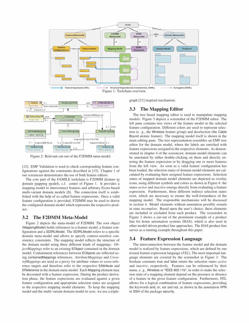
Ecore
Feature Metamodel Domain MetamodelF2DMM
Metamodel
Feature ModelFeature
Configuration XDomain Model Product X
Instance of
Instance of Instance of
Instance of Instance of Instance of Instance of
Mapping Model
Inst
ance
of
Feature Expressions (FEL) Structural Dependencies (Containment, SDIRL)
SDIRLDocument
uses
SDIRLMetamodel
Instance of
Inst
ance
of
refers to
Surrogates (SDIRL)
refers to
Figure 1: Toolchain overview.
Figure 2: Relevant cut-out of the F2DMM meta-model.
[12]. EMF Validation is used to check corresponding feature con-figurations against the constraints described in [15]. Chapter 1 ofour screencast demonstrates the use of both feature editors.
The core part of the FAMILE toolchain is F2DMM (feature todomain mapping model), c.f. center of Figure 1. It provides amapping model to interconnect features and arbitrary Ecore-basedmulti-variant domain models [8]. The connection itself is estab-lished with the help of so called feature expressions. Once a validfeature configuration is provided, F2DMM may be used to derivethe configured domain model which represents the respective prod-uct.
3.2 The F2DMM Meta-ModelFigure 2 depicts the meta-model of F2DMM. The root object
(MappingModel) holds references to a feature model, a feature con-figuration and a SDIRLModel. The SDIRLModel refers to a specificdomain meta-model and allows to specify context-sensitive con-sistency constraints. The mapping model reflects the structure ofthe domain model using three different kinds of mappings: Ob-jectMappings refer to an existing EObject contained in the domainmodel. Containment references between EObjects are reflected us-ing containedMappings references. AttributeMappings and Cross-refMappings are used as a proxy for attribute values or cross-refe-rence targets and therefore refer to the respective EAttribute andEReference in the domain meta-model. Each Mapping element maybe decorated with a feature expression. During the product deriva-tion phase, the feature expressions are evaluated against a givenfeature configuration and appropriate selection states are assignedto the respective mapping model elements. To keep the mappingmodel and the multi-variant domain model in sync, we use a triple-
graph [21] inspired mechanism.
3.3 The Mapping EditorThe tree based mapping editor is used to manipulate mapping
models. Figure 3 depicts a screenshot of the F2DMM editor. Theleft pane contains tree views of the feature model or the selectedfeature configuration. Different colors are used to represent selec-tion (e. g., the Wireless feature group) and deselection (the CableBound atomic feature). The mapping model itself is shown in themain editing pane. The tree representation resembles an EMF treeeditor for the domain model, where the labels are enriched withfeature expressions assigned to the respective elements. As demon-strated in chapter 4 of the screencast, domain model elements canbe annotated by either double-clicking on them and directly en-tering the feature expression or by dragging one or more featuresfrom the left view. As soon as a valid feature configuration hasbeen loaded, the selection states of domain model elements are cal-culated by evaluating their assigned feature expressions. Selectionstates of mapped domain model elements are depicted as overlayicons, using different symbols and colors as shown in Figure 4: thestates active and inactive emerge directly from evaluating a featureexpression. Furthermore, three different indirect selection statesexist, which are necessary to ensure the well-formedness of themapping model. The responsible mechanisms will be discussedin section 4. Model elements without annotation possibly remainin state incomplete. Based upon the user’s choice, these elementsare included or excluded from each product. The screenshot inFigure 3 shows a cut-out of the prominent example of a productline for home automation systems (HAS), which is also used inother model-driven product line approaches. The HAS product lineserves as a running example throughout this paper.
3.4 Feature Expression LanguageThe interconnection between the feature model and the domain
model is realized by feature expressions, which are defined by ourtextual feature expression language (FEL). The most important lan-guage elements are covered by the screenshot in Figure 3: Theboolean constants true and false return the selection states activeand inactive, respectively. Features can be referenced by theirname, e. g., Wireless or "IEEE 802.11b", in order to make the selec-tion state of a mapping element depend on the presence or absenceof a feature in the given feature configuration. Furthermore, FELallows for a logical combination of feature expressions, providingthe keywords and, or, xor and not, as shown in the annotation VPNor SSH of the package security.
38
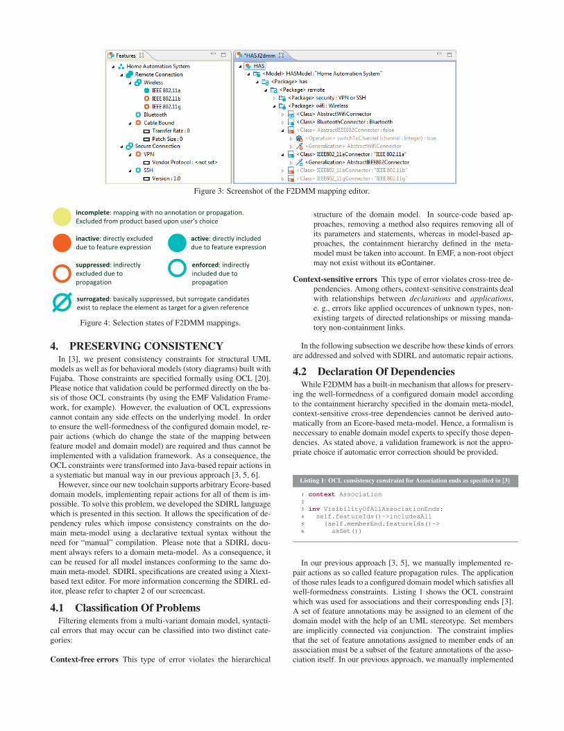
Figure 3: Screenshot of the F2DMM mapping editor.
inactive: directly excluded due to feature expression
active: directly included due to feature expression
incomplete: mapping with no annotation or propagation. Excluded from product based upon user’s choice
suppressed: indirectly excluded due to propagation
enforced: indirectly included due to propagation
surrogated: basically suppressed, but surrogate candidates exist to replace the element as target for a given reference
Figure 4: Selection states of F2DMM mappings.
4. PRESERVING CONSISTENCYIn [3], we present consistency constraints for structural UML
models as well as for behavioral models (story diagrams) built withFujaba. Those constraints are specified formally using OCL [20].Please notice that validation could be performed directly on the ba-sis of those OCL constraints (by using the EMF Validation Frame-work, for example). However, the evaluation of OCL expressionscannot contain any side effects on the underlying model. In orderto ensure the well-formedness of the configured domain model, re-pair actions (which do change the state of the mapping betweenfeature model and domain model) are required and thus cannot beimplemented with a validation framework. As a consequence, theOCL constraints were transformed into Java-based repair actions ina systematic but manual way in our previous approach [3, 5, 6].
However, since our new toolchain supports arbitrary Ecore-baseddomain models, implementing repair actions for all of them is im-possible. To solve this problem, we developed the SDIRL languagewhich is presented in this section. It allows the specification of de-pendency rules which impose consistency constraints on the do-main meta-model using a declarative textual syntax without theneed for “manual” compilation. Please note that a SDIRL docu-ment always refers to a domain meta-model. As a consequence, itcan be reused for all model instances conforming to the same do-main meta-model. SDIRL specifications are created using a Xtext-based text editor. For more information concerning the SDIRL ed-itor, please refer to chapter 2 of our screencast.
4.1 Classification Of ProblemsFiltering elements from a multi-variant domain model, syntacti-
cal errors that may occur can be classified into two distinct cate-gories:
Context-free errors This type of error violates the hierarchical
structure of the domain model. In source-code based ap-proaches, removing a method also requires removing all ofits parameters and statements, whereas in model-based ap-proaches, the containment hierarchy defined in the meta-model must be taken into account. In EMF, a non-root objectmay not exist without its eContainer.
Context-sensitive errors This type of error violates cross-tree de-pendencies. Among others, context-sensitive constraints dealwith relationships between declarations and applications,e. g., errors like applied occurences of unknown types, non-existing targets of directed relationships or missing manda-tory non-containment links.
In the following subsection we describe how these kinds of errorsare addressed and solved with SDIRL and automatic repair actions.
4.2 Declaration Of DependenciesWhile F2DMM has a built-in mechanism that allows for preserv-
ing the well-formedness of a configured domain model accordingto the containment hierarchy specified in the domain meta-model,context-sensitive cross-tree dependencies cannot be derived auto-matically from an Ecore-based meta-model. Hence, a formalism isneccessary to enable domain model experts to specify those depen-dencies. As stated above, a validation framework is not the appro-priate choice if automatic error correction should be provided.
Listing 1: OCL consistency constraint for Association ends as specified in [3]
1 context Association2
3 inv VisibilityOfAllAssociationEnds:4 self.featureIds()->includesAll5 (self.memberEnd.featureIds()->6 asSet())
In our previous approach [3, 5], we manually implemented re-pair actions as so called feature propagation rules. The applicationof those rules leads to a configured domain model which satisfies allwell-formedness constraints. Listing 1 shows the OCL constraintwhich was used for associations and their corresponding ends [3].A set of feature annotations may be assigned to an element of thedomain model with the help of an UML stereotype. Set membersare implicitly connected via conjunction. The constraint impliesthat the set of feature annotations assigned to member ends of anassociation must be a subset of the feature annotations of the asso-ciation itself. In our previous approach, we manually implemented
39
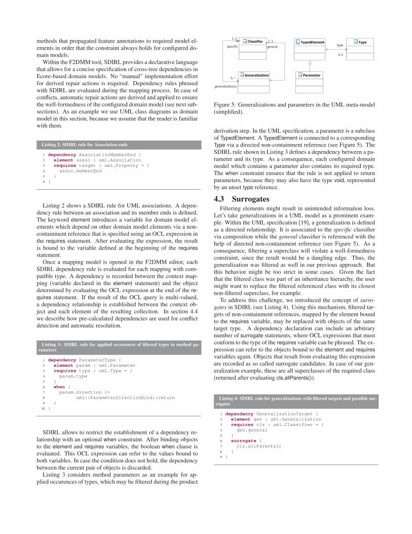
methods that propagated feature annotations to required model el-ements in order that the constraint always holds for configured do-main models.
Within the F2DMM tool, SDIRL provides a declarative languagethat allows for a concise specification of cross-tree dependencies inEcore-based domain models. No “manual” implementation effortfor derived repair actions is required. Dependency rules phrasedwith SDIRL are evaluated during the mapping process. In case ofconflicts, automatic repair actions are derived and applied to ensurethe well-formedness of the configured domain model (see next sub-sections). As an example we use UML class diagrams as domainmodel in this section, because we assume that the reader is familiarwith them.
Listing 2: SDIRL rule for Association ends
1 dependency AssociationMemberEnd {2 element assoc : uml.Association3 requires target : uml.Property = {4 assoc.memberEnd5 }6 }
Listing 2 shows a SDIRL rule for UML associations. A depen-dency rule between an association and its member ends is defined.The keyword element introduces a variable for domain model el-ements which depend on other domain model elements via a non-containment reference that is specified using an OCL expression inthe requires statement. After evaluating the expression, the resultis bound to the variable defined at the beginning of the requiresstatement.
Once a mapping model is opened in the F2DMM editor, eachSDIRL dependency rule is evaluated for each mapping with com-patible type. A dependency is recorded between the context map-ping (variable declared in the element statement) and the objectdetermined by evaluating the OCL expression at the end of the re-quires statement. If the result of the OCL query is multi-valued,a dependency relationship is established between the context ob-ject and each element of the resulting collection. In section 4.4we describe how pre-calculated dependencies are used for conflictdetection and automatic resolution.
Listing 3: SDIRL rule for applied occurences of filtered types in method pa-rameters
1 dependency ParameterType {2 element param : uml.Parameter3 requires type : uml.Type = {4 param.type5 }6 when {7 param.direction <>8 uml::ParameterDirectionKind::return9 }
10 }
SDIRL allows to restrict the establishment of a dependency re-lationship with an optional when constraint. After binding objectsto the element and requires variables, the boolean when clause isevaluated. This OCL expression can refer to the values bound toboth variables. In case the condition does not hold, the dependencybetween the current pair of objects is discarded.
Listing 3 considers method parameters as an example for ap-plied occurences of types, which may be filtered during the product
Figure 5: Generalizations and parameters in the UML meta-model(simplified).
derivation step. In the UML specification, a parameter is a subclassof TypedElement. A TypedElement is connected to a correspondingType via a directed non-containment reference (see Figure 5). TheSDIRL rule shown in Listing 3 defines a dependency between a pa-rameter and its type. As a consequence, each configured domainmodel which contains a parameter also contains its required type.The when constraint ensures that the rule is not applied to returnparameters, because they may also have the type void, representedby an unset type reference.
4.3 SurrogatesFiltering elements might result in unintended information loss.
Let’s take generalizations in a UML model as a prominent exam-ple. Within the UML specification [19], a generalization is definedas a directed relationship. It is associated to the specific classifiervia composition while the general classifier is referenced with thehelp of directed non-containment reference (see Figure 5). As aconsequence, filtering a superclass will violate a well-formednessconstraint, since the result would be a dangling edge. Thus, thegeneralization was filtered as well in our previous approach. Butthis behavior might be too strict in some cases. Given the factthat the filtered class was part of an inheritance hierarchy, the usermight want to replace the filtered referenced class with its closestnon-filtered superclass, for example.
To address this challenge, we introduced the concept of surro-gates in SDIRL (see Listing 4). Using this mechanism, filtered tar-gets of non-containment references, mapped by the element boundto the requires variable, may be replaced with objects of the sametarget type. A dependency declaration can include an arbitrarynumber of surrogate statements, where OCL expressions that mustconform to the type of the requires variable can be phrased. The ex-pression can refer to the objects bound to the element and requiresvariables again. Objects that result from evaluating this expressionare recorded as so called surrogate candidates. In case of our gen-eralization example, these are all superclasses of the required class(returned after evaluating cls.allParents()).
Listing 4: SDIRL rule for generalizations with filtered targets and possible sur-rogates
1 dependency GeneralizationTarget {2 element gen : uml.Generalization3 requires cls : uml.Classifier = {4 gen.general5 }6 surrogate {7 cls.allParents()8 }9 }
40
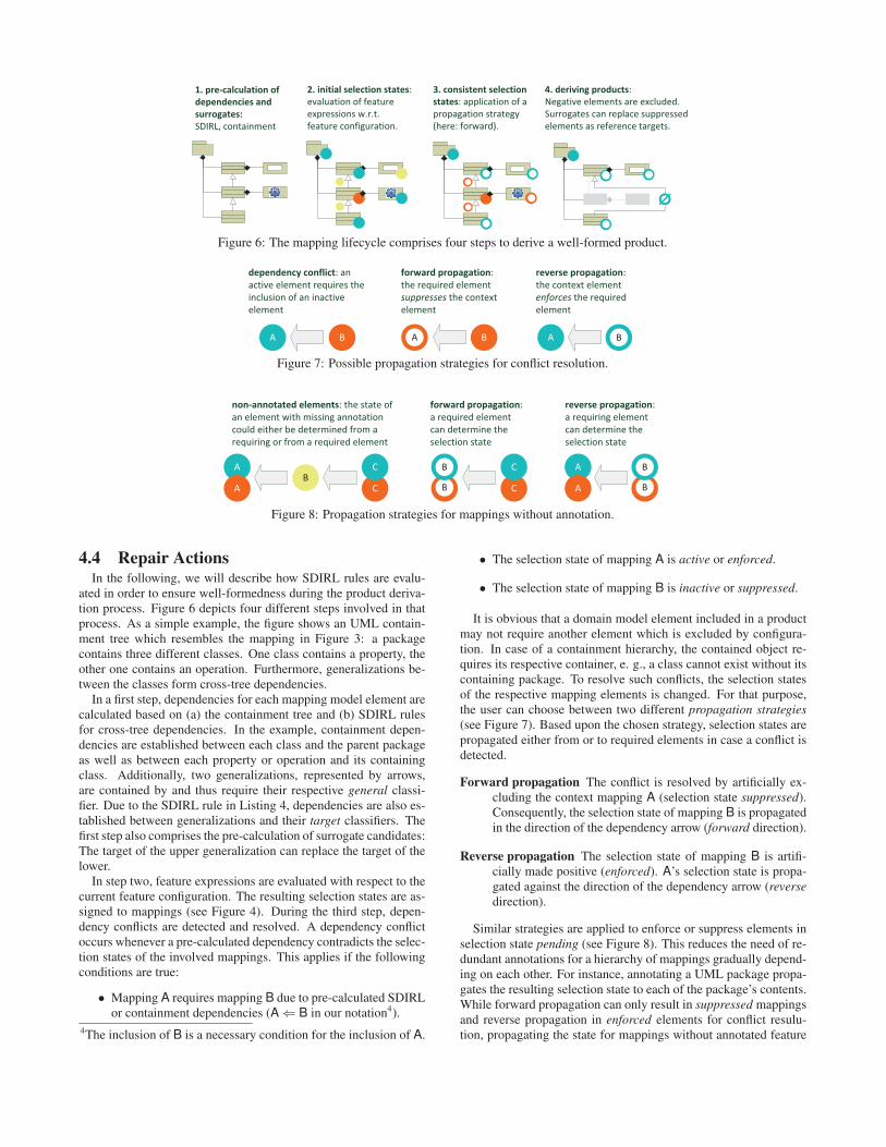
1. pre-calculation of dependencies and surrogates: SDIRL, containment
2. initial selection states:evaluation of feature expressions w.r.t.feature configuration.
3. consistent selection states: application of a propagation strategy (here: forward).
4. deriving products: Negative elements are excluded. Surrogates can replace suppressed elements as reference targets.
Figure 6: The mapping lifecycle comprises four steps to derive a well-formed product.
A B
dependency conflict: an active element requires the inclusion of an inactive element
forward propagation:the required element suppresses the context element
reverse propagation:the context element enforces the required element
A BB A
Figure 7: Possible propagation strategies for conflict resolution.
AB
non-annotated elements: the state of an element with missing annotation could either be determined from a requiring or from a required element
forward propagation:a required element can determine the selection state
reverse propagation:a requiring element can determine theselection state
C
C
A C
C A
AB
B
B
B
Figure 8: Propagation strategies for mappings without annotation.
4.4 Repair ActionsIn the following, we will describe how SDIRL rules are evalu-
ated in order to ensure well-formedness during the product deriva-tion process. Figure 6 depicts four different steps involved in thatprocess. As a simple example, the figure shows an UML contain-ment tree which resembles the mapping in Figure 3: a packagecontains three different classes. One class contains a property, theother one contains an operation. Furthermore, generalizations be-tween the classes form cross-tree dependencies.
In a first step, dependencies for each mapping model element arecalculated based on (a) the containment tree and (b) SDIRL rulesfor cross-tree dependencies. In the example, containment depen-dencies are established between each class and the parent packageas well as between each property or operation and its containingclass. Additionally, two generalizations, represented by arrows,are contained by and thus require their respective general classi-fier. Due to the SDIRL rule in Listing 4, dependencies are also es-tablished between generalizations and their target classifiers. Thefirst step also comprises the pre-calculation of surrogate candidates:The target of the upper generalization can replace the target of thelower.
In step two, feature expressions are evaluated with respect to thecurrent feature configuration. The resulting selection states are as-signed to mappings (see Figure 4). During the third step, depen-dency conflicts are detected and resolved. A dependency conflictoccurs whenever a pre-calculated dependency contradicts the selec-tion states of the involved mappings. This applies if the followingconditions are true:
• Mapping A requires mapping B due to pre-calculated SDIRLor containment dependencies (A ⇐ B in our notation4).
4The inclusion of B is a necessary condition for the inclusion of A.
• The selection state of mapping A is active or enforced.
• The selection state of mapping B is inactive or suppressed.
It is obvious that a domain model element included in a productmay not require another element which is excluded by configura-tion. In case of a containment hierarchy, the contained object re-quires its respective container, e. g., a class cannot exist without itscontaining package. To resolve such conflicts, the selection statesof the respective mapping elements is changed. For that purpose,the user can choose between two different propagation strategies(see Figure 7). Based upon the chosen strategy, selection states arepropagated either from or to required elements in case a conflict isdetected.
Forward propagation The conflict is resolved by artificially ex-cluding the context mapping A (selection state suppressed).Consequently, the selection state of mapping B is propagatedin the direction of the dependency arrow (forward direction).
Reverse propagation The selection state of mapping B is artifi-cially made positive (enforced). A’s selection state is propa-gated against the direction of the dependency arrow (reversedirection).
Similar strategies are applied to enforce or suppress elements inselection state pending (see Figure 8). This reduces the need of re-dundant annotations for a hierarchy of mappings gradually depend-ing on each other. For instance, annotating a UML package propa-gates the resulting selection state to each of the package’s contents.While forward propagation can only result in suppressed mappingsand reverse propagation in enforced elements for conflict resulu-tion, propagating the state for mappings without annotated feature
41
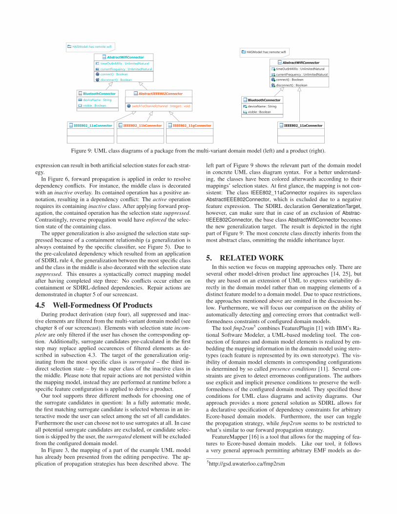
Figure 9: UML class diagrams of a package from the multi-variant domain model (left) and a product (right).
expression can result in both artificial selection states for each strat-egy.
In Figure 6, forward propagation is applied in order to resolvedependency conflicts. For instance, the middle class is decoratedwith an inactive overlay. Its contained operation has a positive an-notation, resulting in a dependency conflict: The active operationrequires its containing inactive class. After applying forward prop-agation, the contained operation has the selection state suppressed.Contrastingly, reverse propagation would have enforced the selec-tion state of the containing class.
The upper generalization is also assigned the selection state sup-pressed because of a containment relationship (a generalization isalways contained by the specific classifier, see Figure 5). Due tothe pre-calculated dependency which resulted from an applicationof SDIRL rule 4, the generalization between the most specific classand the class in the middle is also decorated with the selection statesuppressed. This ensures a syntactically correct mapping modelafter having completed step three: No conflicts occur either oncontainment or SDIRL-defined dependencies. Repair actions aredemonstrated in chapter 5 of our screencast.
4.5 Well-Formedness Of ProductsDuring product derivation (step four), all suppressed and inac-
tive elements are filtered from the multi-variant domain model (seechapter 8 of our screencast). Elements with selection state incom-plete are only filtered if the user has chosen the corresponding op-tion. Additionally, surrogate candidates pre-calculated in the firststep may replace applied occurences of filtered elements as de-scribed in subsection 4.3. The target of the generalization orig-inating from the most specific class is surrogated – the third in-direct selection state – by the super class of the inactive class inthe middle. Please note that repair actions are not persisted withinthe mapping model, instead they are performed at runtime before aspecific feature configuration is applied to derive a product.
Our tool supports three different methods for choosing one ofthe surrogate candidates in question: In a fully automatic mode,the first matching surrogate candidate is selected whereas in an in-teractive mode the user can select among the set of all candidates.Furthermore the user can choose not to use surrogates at all. In caseall potential surrogate candidates are excluded, or candidate selec-tion is skipped by the user, the surrogated element will be excludedfrom the configured domain model.
In Figure 3, the mapping of a part of the example UML modelhas already been presented from the editing perspective. The ap-plication of propagation strategies has been described above. The
left part of Figure 9 shows the relevant part of the domain modelin concrete UML class diagram syntax. For a better understand-ing, the classes have been colored afterwards according to theirmappings’ selection states. At first glance, the mapping is not con-sistent: The class IEEE802_11aConnector requires its superclassAbstractIEEE802Connector, which is excluded due to a negativefeature expression. The SDIRL declaration GeneralizationTarget,however, can make sure that in case of an exclusion of Abstrac-tIEEE802Connector, the base class AbstractWifiConnector becomesthe new generalization target. The result is depicted in the rightpart of Figure 9: The most concrete class directly inherits from themost abstract class, ommitting the middle inheritance layer.
5. RELATED WORKIn this section we focus on mapping approaches only. There are
several other model-driven product line approaches [14, 25], butthey are based on an extension of UML to express variability di-rectly in the domain model rather than on mapping elements of adistinct feature model to a domain model. Due to space restrictions,the approaches mentioned above are omitted in the discussion be-low. Furthermore, we will focus our comparison on the ability ofautomatically detecting and correcting errors that contradict well-formedness constraints of configured domain models.
The tool fmp2rsm5 combines FeaturePlugin [1] with IBM’s Ra-tional Software Modeler, a UML-based modeling tool. The con-nection of features and domain model elements is realized by em-bedding the mapping information in the domain model using stero-types (each feature is represented by its own stereotype). The vis-ibility of domain model elements in corresponding configurationsis determined by so called presence conditions [11]. Several con-straints are given to detect errorneous configurations. The authorsuse explicit and implicit presence conditions to preserve the well-formedness of the configured domain model. They specified thoseconditions for UML class diagrams and activity diagrams. Ourapproach provides a more general solution as SDIRL allows fora declarative specification of dependency constraints for arbitraryEcore-based domain models. Furthermore, the user can togglethe propagation strategy, while fmp2rsm seems to be restricted towhat’s similar to our forward propagation strategy.
FeatureMapper [16] is a tool that allows for the mapping of fea-tures to Ecore-based domain models. Like our tool, it followsa very general approach permitting arbitrary EMF models as do-
5http://gsd.uwaterloo.ca/fmp2rsm
42
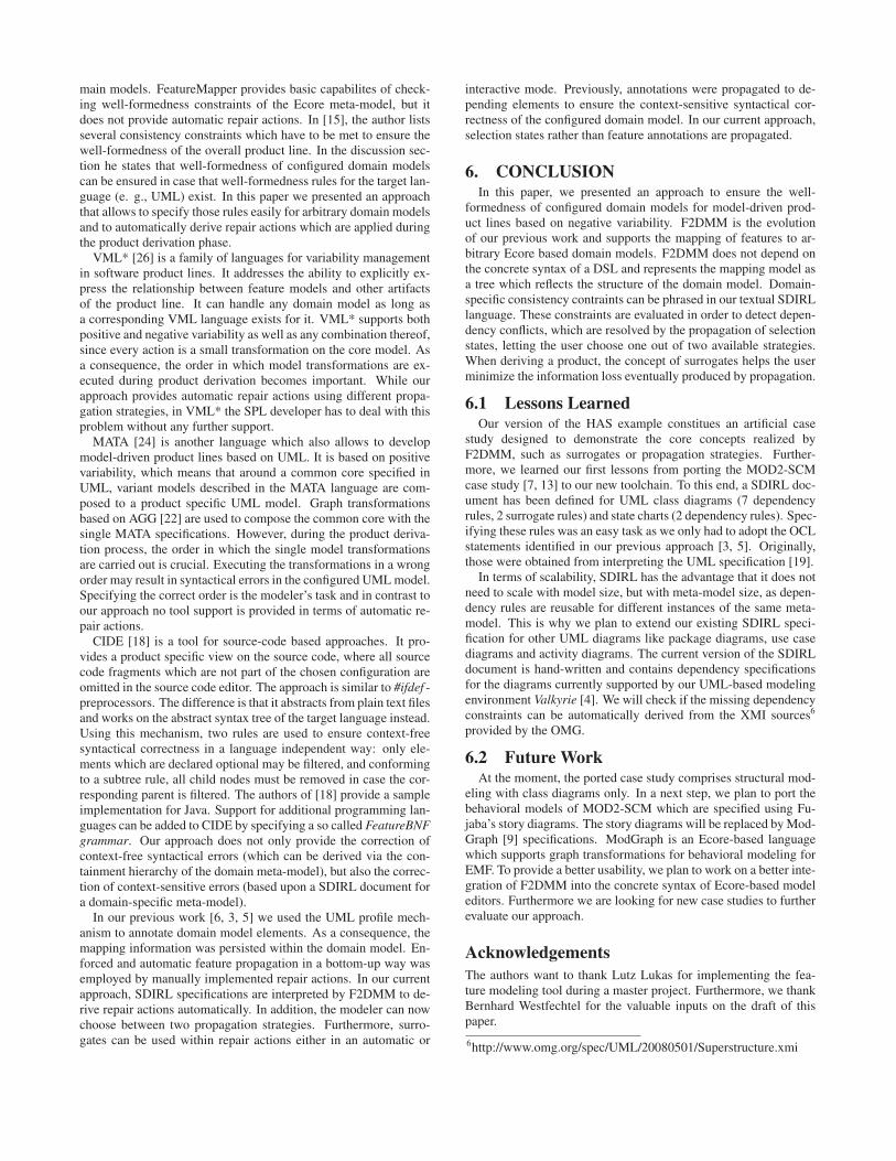
main models. FeatureMapper provides basic capabilites of check-ing well-formedness constraints of the Ecore meta-model, but itdoes not provide automatic repair actions. In [15], the author listsseveral consistency constraints which have to be met to ensure thewell-formedness of the overall product line. In the discussion sec-tion he states that well-formedness of configured domain modelscan be ensured in case that well-formedness rules for the target lan-guage (e. g., UML) exist. In this paper we presented an approachthat allows to specify those rules easily for arbitrary domain modelsand to automatically derive repair actions which are applied duringthe product derivation phase.
VML* [26] is a family of languages for variability managementin software product lines. It addresses the ability to explicitly ex-press the relationship between feature models and other artifactsof the product line. It can handle any domain model as long asa corresponding VML language exists for it. VML* supports bothpositive and negative variability as well as any combination thereof,since every action is a small transformation on the core model. Asa consequence, the order in which model transformations are ex-ecuted during product derivation becomes important. While ourapproach provides automatic repair actions using different propa-gation strategies, in VML* the SPL developer has to deal with thisproblem without any further support.
MATA [24] is another language which also allows to developmodel-driven product lines based on UML. It is based on positivevariability, which means that around a common core specified inUML, variant models described in the MATA language are com-posed to a product specific UML model. Graph transformationsbased on AGG [22] are used to compose the common core with thesingle MATA specifications. However, during the product deriva-tion process, the order in which the single model transformationsare carried out is crucial. Executing the transformations in a wrongorder may result in syntactical errors in the configured UML model.Specifying the correct order is the modeler’s task and in contrast toour approach no tool support is provided in terms of automatic re-pair actions.
CIDE [18] is a tool for source-code based approaches. It pro-vides a product specific view on the source code, where all sourcecode fragments which are not part of the chosen configuration areomitted in the source code editor. The approach is similar to #ifdef -preprocessors. The difference is that it abstracts from plain text filesand works on the abstract syntax tree of the target language instead.Using this mechanism, two rules are used to ensure context-freesyntactical correctness in a language independent way: only ele-ments which are declared optional may be filtered, and conformingto a subtree rule, all child nodes must be removed in case the cor-responding parent is filtered. The authors of [18] provide a sampleimplementation for Java. Support for additional programming lan-guages can be added to CIDE by specifying a so called FeatureBNFgrammar. Our approach does not only provide the correction ofcontext-free syntactical errors (which can be derived via the con-tainment hierarchy of the domain meta-model), but also the correc-tion of context-sensitive errors (based upon a SDIRL document fora domain-specific meta-model).
In our previous work [6, 3, 5] we used the UML profile mech-anism to annotate domain model elements. As a consequence, themapping information was persisted within the domain model. En-forced and automatic feature propagation in a bottom-up way wasemployed by manually implemented repair actions. In our currentapproach, SDIRL specifications are interpreted by F2DMM to de-rive repair actions automatically. In addition, the modeler can nowchoose between two propagation strategies. Furthermore, surro-gates can be used within repair actions either in an automatic or
interactive mode. Previously, annotations were propagated to de-pending elements to ensure the context-sensitive syntactical cor-rectness of the configured domain model. In our current approach,selection states rather than feature annotations are propagated.
6. CONCLUSIONIn this paper, we presented an approach to ensure the well-
formedness of configured domain models for model-driven prod-uct lines based on negative variability. F2DMM is the evolutionof our previous work and supports the mapping of features to ar-bitrary Ecore based domain models. F2DMM does not depend onthe concrete syntax of a DSL and represents the mapping model asa tree which reflects the structure of the domain model. Domain-specific consistency contraints can be phrased in our textual SDIRLlanguage. These constraints are evaluated in order to detect depen-dency conflicts, which are resolved by the propagation of selectionstates, letting the user choose one out of two available strategies.When deriving a product, the concept of surrogates helps the userminimize the information loss eventually produced by propagation.
6.1 Lessons LearnedOur version of the HAS example constitues an artificial case
study designed to demonstrate the core concepts realized byF2DMM, such as surrogates or propagation strategies. Further-more, we learned our first lessons from porting the MOD2-SCMcase study [7, 13] to our new toolchain. To this end, a SDIRL doc-ument has been defined for UML class diagrams (7 dependencyrules, 2 surrogate rules) and state charts (2 dependency rules). Spec-ifying these rules was an easy task as we only had to adopt the OCLstatements identified in our previous approach [3, 5]. Originally,those were obtained from interpreting the UML specification [19].
In terms of scalability, SDIRL has the advantage that it does notneed to scale with model size, but with meta-model size, as depen-dency rules are reusable for different instances of the same meta-model. This is why we plan to extend our existing SDIRL speci-fication for other UML diagrams like package diagrams, use casediagrams and activity diagrams. The current version of the SDIRLdocument is hand-written and contains dependency specificationsfor the diagrams currently supported by our UML-based modelingenvironment Valkyrie [4]. We will check if the missing dependencyconstraints can be automatically derived from the XMI sources6
provided by the OMG.
6.2 Future WorkAt the moment, the ported case study comprises structural mod-
eling with class diagrams only. In a next step, we plan to port thebehavioral models of MOD2-SCM which are specified using Fu-jaba’s story diagrams. The story diagrams will be replaced by Mod-Graph [9] specifications. ModGraph is an Ecore-based languagewhich supports graph transformations for behavioral modeling forEMF. To provide a better usability, we plan to work on a better inte-gration of F2DMM into the concrete syntax of Ecore-based modeleditors. Furthermore we are looking for new case studies to furtherevaluate our approach.
AcknowledgementsThe authors want to thank Lutz Lukas for implementing the fea-ture modeling tool during a master project. Furthermore, we thankBernhard Westfechtel for the valuable inputs on the draft of thispaper.
6http://www.omg.org/spec/UML/20080501/Superstructure.xmi
43
7. REFERENCES[1] M. Antkiewicz and K. Czarnecki. FeaturePlugin: Feature
modeling plug-in for Eclipse. In Proceedings of the 2004OOPSLA Workshop on Eclipse Technology eXchange(eclipse’04), pages 67–72, New York, NY, 2004.
[2] D. S. Batory. Feature models, grammars, and propositionalformulas. In J. H. Obbink and K. Pohl, editors, Proceedingsof the 9th International Software Product Line Conference(SPLC’05), volume 3714 of Lecture Notes in ComputerScience, pages 7–20, Rennes, France, Sept. 2005. SpringerVerlag.
[3] T. Buchmann. Modelle und Werkzeuge für modellgetriebeneSoftwareproduktlinien am Beispiel vonSoftwarekonfigurationsverwaltungssystemen. Phd thesis,University of Bayreuth, 2010.
[4] T. Buchmann. Valkyrie: A UML-based Model-drivenEnvironment for Model-driven Software Engineering. InS. Hammoudi, M. van Sinderen, and J. Cordeiro, editors,Proceedings of the 7th International Conference on SoftwareParadigm Trends (ICSOFT 2012), pages 147–157, Rome,Italy, July 2012. INSTICC Press.
[5] T. Buchmann and A. Dotor. Constraints for a fine-grainedmapping of feature models and executable domain models.In M. Mezini, D. Beuche, and A. Moreira, editors,Proceedings of the 1st International Workshop onModel-Driven Product Line Engineering (MDPLE’09),CTIT Workshop Proceedings, pages 9–17, Twente, TheNetherlands, June 2009. CTIT.
[6] T. Buchmann and A. Dotor. Mapping features to domainmodels in fujaba. In P. van Gorp, editor, Proceedings of the7th International Fujaba Days, pages 20–24, Eindhoven,The Netherlands, Nov. 2009.
[7] T. Buchmann, A. Dotor, and B. Westfechtel. MOD2-SCM: Amodel-driven product line for software configurationmanagement systems. Information and Software Technology,2012. http://dx.doi.org/10.1016/j.infsof.2012.07.010.
[8] T. Buchmann and F. Schwägerl. FAMILE: tool support forevolving model-driven product lines. In H. Störrle,G. Botterweck, M. Bourdellès, D. Kolovos, R. Paige,E. Roubtsova, J. Rubin, and J.-P. Tolvanen, editors, JointProceedings of co-located Events at the 8th EuropeanConference on Modelling Foundations and Applications,CEUR WS, pages 59–62, Building 321, DK-2800 KongensLyngby, July 2012. Technical University of Denmark (DTU).
[9] T. Buchmann, B. Westfechtel, and S. Winetzhammer.MODGRAPH - A Transformation Engine for EMF ModelTransformations. In Proceedings of the 6th InternationalConference on Software and Data Technologies, pages 212 –219, 2011.
[10] P. Clements and L. Northrop. Software Product Lines:Practices and Patterns. Boston, MA, 2001.
[11] K. Czarnecki and M. Antkiewicz. Mapping features tomodels: A template approach based on superimposedvariants. In R. Glück and M. R. Lowry, editors, 4thInternational Conference on Generative Programming andComponent Engineering (GPCE 2005), volume 3676 ofLecture Notes in Computer Science, pages 422–437, Tallin,Estonia, Sept. 2005. Springer Verlag.
[12] K. Czarnecki, S. Helsen, and U. W. Eisenecker. Formalizingcardinality-based feature models and their specialization.Software Process: Improvement and Practice, 10(1):7–29,2005.
[13] A. Dotor. Entwurf und Modellierung einer Produktlinie vonSoftware-Konfigurations-Management-Systemen. PhD thesis,University of Bayreuth, 2011.
[14] H. Gomaa. Designing Software Product Lines with UML:From Use Cases to Pattern-Based Software Architectures.Addison-Wesley, Boston, MA, 2004.
[15] F. Heidenreich. Towards systematic ensuringwell-formedness of software product lines. In Proceedings ofthe 1st Workshop on Feature-Oriented SoftwareDevelopment, pages 69–74, Denver, CO, USA, Oct. 2009.ACM.
[16] F. Heidenreich, J. Kopcsek, and C. Wende. FeatureMapper:Mapping features to models. In Companion Proceedings ofthe 30th International Conference on Software Engineering(ICSE’08), pages 943–944, Leipzig, Germany, May 2008.
[17] K. C. Kang, S. G. Cohen, J. A. Hess, W. E. Novak, and A. S.Peterson. Feature-oriented domain analysis (FODA)feasibility study. Technical Report CMU/SEI-90-TR-21,Carnegie-Mellon University, Software Engineering Institute,Nov. 1990.
[18] C. Kästner, S. Apel, S. Trujillo, M. Kuhlemann, and D. S.Batory. Guaranteeing syntactic correctness for all productline variants: A language-independent approach. In M. Orioland B. Meyer, editors, TOOLS (47), volume 33 of LectureNotes in Business Information Processing, pages 175–194.Springer, 2009.
[19] OMG. UML Superstructure. Object Management Group,Needham, MA, formal/2011-08-06 edition, Aug. 2011.
[20] OMG. Object Constraint Language. Object ManagementGroup, Needham, MA, formal/2012-01-01 edition, Jan.2012.
[21] A. Schürr. Specification of Graph Translators with TripleGraph Grammars. Technical report, RWTH Aachen, 1994.
[22] G. Taentzer. AGG: A Graph Transformation Environment forModeling and Validation of Software. In J. Pfaltz, M. Nagl,and B. Böhlen, editors, Applications of GraphTransformations with Industrial Relevance, volume 3062 ofLecture Notes in Computer Science, pages 446–453. SpringerBerlin / Heidelberg, Charlottesville, VA, USA, 2004.
[23] M. Völter, T. Stahl, J. Bettin, A. Haase, and S. Helsen.Model-Driven Software Development: Technology,Engineering, Management. John Wiley & Sons, 2006.
[24] J. Whittle, P. Jayaraman, A. Elkhodary, A. Moreira, andJ. Araújo. MATA: A Unified Approach for Composing UMLAspect Models Based on Graph Transformation. In S. Katz,H. Ossher, R. France, and J.-M. Jézéquel, editors,Transactions on Aspect-Oriented Software Development VI,volume 5560 of Lecture Notes in Computer Science, pages191–237. Springer Berlin / Heidelberg, 2009.
[25] T. Ziadi and J.-M. Jézéquel. Software Product LineEngineering with the UML: Deriving Products. In T. Käkölaand J. C. Duenas, editors, Software Product Lines, pages557–588. Springer Berlin / Heidelberg, 2006.
[26] S. Zschaler, P. Sánchez, J. Santos, M. Alférez, A. Rashid,L. Fuentes, A. Moreira, J. Araújo, and U. Kulesza. VML* -A Family of Languages for Variability Management inSoftware Product Lines. In M. van den Brand, D. Gasevic,and J. Gray, editors, Software Language Engineering,volume 5969 of Lecture Notes in Computer Science, pages82–102. Springer Berlin / Heidelberg, Denver, CO, USA,2010.
44
Supporting Multiple Feature Binding Strategies in NX
Stefan Sobernig Gustaf Neumann Stephan Adelsberger
Institute for Information Systems and New MediaWU Vienna
Austria{firstname}.{lastname}@wu.ac.at
ABSTRACT
Feature-oriented programming (FOP) toolkits restrict im-plementers of software product lines to certain implemen-tation choices. One is left with the choices between, forexample, class-level or object-level extensions and betweenstatic or dynamic feature bindings. These choices are typ-ically made at an early development stage causing an un-wanted lock-in. We present a feature-oriented developmentframework based on dynamic, object-oriented constructs fordeferring such design decisions by piggybacking on first-classlanguage entities (metaclasses, mixins). A framework proto-type is available for the scripting language NX. NX providesthe required object-oriented language infrastructure: a re-flective language model, metaclasses, multiple class-basedinheritance, decorator mixins, and open entity declarations.We exemplify the approach based on a Graph Product Line.
Categories and Subject Descriptors
D.3.2 [Programming Languages]: Language Classifi-cations—Object-oriented languages, Scripting languages;D.3.3 [Programming Languages]: Language Constructsand Features
General Terms
Design, Languages
Keywords
Dynamic software product lines, feature-oriented program-ming, dynamic feature binding, static feature binding
1. INTRODUCTIONA software product line (SPL) provides a common code
base for a family of related software products and a prod-uct line model (e.g., a feature model) specifying the set ofvalid products which can be built from the product line. Animportant approach to constructing software product linesin an object-oriented (OO) programming environment arecollaboration-based designs [23].
Permission to make digital or hard copies of all or part of this work forpersonal or classroom use is granted without fee provided that copies arenot made or distributed for profit or commercial advantage and that copiesbear this notice and the full citation on the first page. To copy otherwise, torepublish, to post on servers or to redistribute to lists, requires prior specificpermission and/or a fee.FOSD’12, September 24–25, 2012, Dresden, Germany.Copyright 2012 ACM 978-1-4503-1309-4/12/09 ...$15.00.
In a collaboration [1], objects and classes interact by ex-changing messages to realize an integrated piece of func-tionality. The base product is a collaboration implementinga domain model using a mix of OO composition strategies(e.g., a structure of associated objects and classes). The im-plementation of a feature is a code unit that is designed toextend the collaborations of the base product. The targetproducts (the instances of the SPL) are built from a set ofsoftware assets comprising the base product and feature im-plementations selected by a valid configuration of the prod-uct line model. Therefore, the composed products embodythe collaboration-based designs of the base product and ofthe feature modules. This step of building an SPL instancebased on feature composition is supported by object-levelcomposition techniques as well as by dedicated approachesfor feature-oriented programming (FOP; [23]).
In order to implement a software product line, variousdesign decisions must be made on the base product andon the individual feature implementations. Important de-cisions are: How is the set of assets organized into separatecode units to be combined into a final product? How canfeature cohesion [9] be achieved for these code units? Howshould object collaborations and their feature-specific refine-ments be expressed and made explicit? Which OO extensionmechanisms could/should be used for feature composition?Is first-class code representation (data structures, objects,classes) of the assets required? Should the target product bea code unit (such as a class) that should be further reusableand refinable? What is the desired feature binding time?In other words, in which program phase are the feature im-plementations included into the product: at design time, atcompile time, at start-up time, or at runtime? What is thedesired/required product granularity: Is the product to berepresented as a collaboration of objects or of classes?
By adopting certain object-compositional techniques ora particular FOP toolkit, many of these decisions must bemade comparatively early in an SPL development cycle. Forexample, the chosen FOP approach (e.g., rbFeatures [6]) andthe underlying OO language (Ruby) determine certain de-cisions due to the programming language’s OO model. ForRuby, this model is class-centric with single, class-based in-heritance and a form of mixin composition based on dy-namic superclass injection. The FOP approach might alsoprovide mandatory abstractions for features (e.g., featureclasses) and products (e.g., product classes). Collaborationsof classes and objects could be expressed in a language-supported manner (e.g., by declaring a namespace per col-laboration). As for the feature composition, the toolkit
45
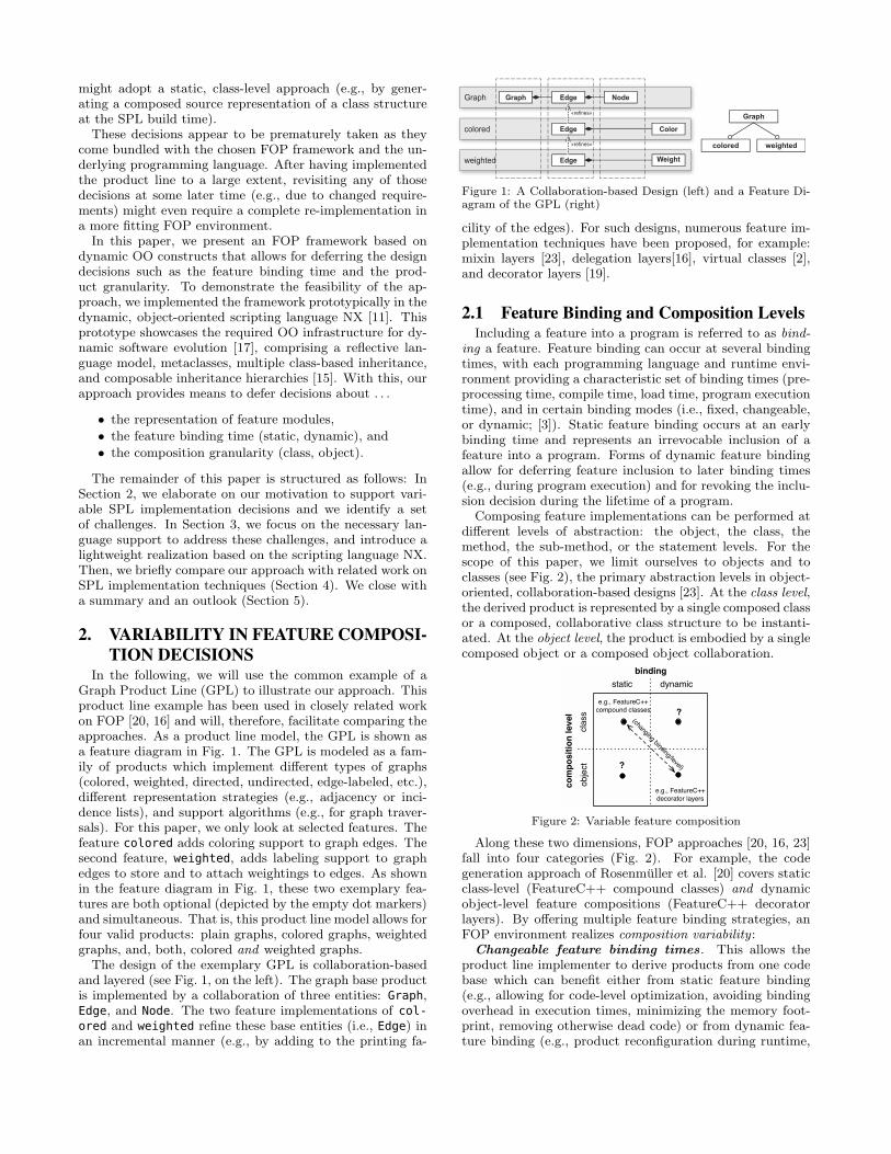
might adopt a static, class-level approach (e.g., by gener-ating a composed source representation of a class structureat the SPL build time).These decisions appear to be prematurely taken as they
come bundled with the chosen FOP framework and the un-derlying programming language. After having implementedthe product line to a large extent, revisiting any of thosedecisions at some later time (e.g., due to changed require-ments) might even require a complete re-implementation ina more fitting FOP environment.In this paper, we present an FOP framework based on
dynamic OO constructs that allows for deferring the designdecisions such as the feature binding time and the prod-uct granularity. To demonstrate the feasibility of the ap-proach, we implemented the framework prototypically in thedynamic, object-oriented scripting language NX [11]. Thisprototype showcases the required OO infrastructure for dy-namic software evolution [17], comprising a reflective lan-guage model, metaclasses, multiple class-based inheritance,and composable inheritance hierarchies [15]. With this, ourapproach provides means to defer decisions about . . .
• the representation of feature modules,
• the feature binding time (static, dynamic), and
• the composition granularity (class, object).
The remainder of this paper is structured as follows: InSection 2, we elaborate on our motivation to support vari-able SPL implementation decisions and we identify a setof challenges. In Section 3, we focus on the necessary lan-guage support to address these challenges, and introduce alightweight realization based on the scripting language NX.Then, we briefly compare our approach with related work onSPL implementation techniques (Section 4). We close witha summary and an outlook (Section 5).
2. VARIABILITY IN FEATURE COMPOSI-
TION DECISIONSIn the following, we will use the common example of a
Graph Product Line (GPL) to illustrate our approach. Thisproduct line example has been used in closely related workon FOP [20, 16] and will, therefore, facilitate comparing theapproaches. As a product line model, the GPL is shown asa feature diagram in Fig. 1. The GPL is modeled as a fam-ily of products which implement different types of graphs(colored, weighted, directed, undirected, edge-labeled, etc.),different representation strategies (e.g., adjacency or inci-dence lists), and support algorithms (e.g., for graph traver-sals). For this paper, we only look at selected features. Thefeature colored adds coloring support to graph edges. Thesecond feature, weighted, adds labeling support to graphedges to store and to attach weightings to edges. As shownin the feature diagram in Fig. 1, these two exemplary fea-tures are both optional (depicted by the empty dot markers)and simultaneous. That is, this product line model allows forfour valid products: plain graphs, colored graphs, weightedgraphs, and, both, colored and weighted graphs.The design of the exemplary GPL is collaboration-based
and layered (see Fig. 1, on the left). The graph base productis implemented by a collaboration of three entities: Graph,Edge, and Node. The two feature implementations of col-ored and weighted refine these base entities (i.e., Edge) inan incremental manner (e.g., by adding to the printing fa-
GraphGraph Edge Node
WeightWeightcolored Color
WeightWeightweighted Weight
«refines»
«refines»
Edge
Edge
Graph
colored weighted
Figure 1: A Collaboration-based Design (left) and a Feature Di-agram of the GPL (right)
cility of the edges). For such designs, numerous feature im-plementation techniques have been proposed, for example:mixin layers [23], delegation layers[16], virtual classes [2],and decorator layers [19].
2.1 Feature Binding and Composition LevelsIncluding a feature into a program is referred to as bind-
ing a feature. Feature binding can occur at several bindingtimes, with each programming language and runtime envi-ronment providing a characteristic set of binding times (pre-processing time, compile time, load time, program executiontime), and in certain binding modes (i.e., fixed, changeable,or dynamic; [3]). Static feature binding occurs at an earlybinding time and represents an irrevocable inclusion of afeature into a program. Forms of dynamic feature bindingallow for deferring feature inclusion to later binding times(e.g., during program execution) and for revoking the inclu-sion decision during the lifetime of a program.
Composing feature implementations can be performed atdifferent levels of abstraction: the object, the class, themethod, the sub-method, or the statement levels. For thescope of this paper, we limit ourselves to objects and toclasses (see Fig. 2), the primary abstraction levels in object-oriented, collaboration-based designs [23]. At the class level,the derived product is represented by a single composed classor a composed, collaborative class structure to be instanti-ated. At the object level, the product is embodied by a singlecomposed object or a composed object collaboration.
static dynamic
binding
class
object
co
mp
os
itio
n l
ev
el
e.g., FeatureC++
compound classes
e.g., FeatureC++
decorator layers
?
?
(changing binding/level)
Figure 2: Variable feature composition
Along these two dimensions, FOP approaches [20, 16, 23]fall into four categories (Fig. 2). For example, the codegeneration approach of Rosenmuller et al. [20] covers staticclass-level (FeatureC++ compound classes) and dynamicobject-level feature compositions (FeatureC++ decoratorlayers). By offering multiple feature binding strategies, anFOP environment realizes composition variability :
Changeable feature binding times . This allows theproduct line implementer to derive products from one codebase which can benefit either from static feature binding(e.g., allowing for code-level optimization, avoiding bindingoverhead in execution times, minimizing the memory foot-print, removing otherwise dead code) or from dynamic fea-ture binding (e.g., product reconfiguration during runtime,
46
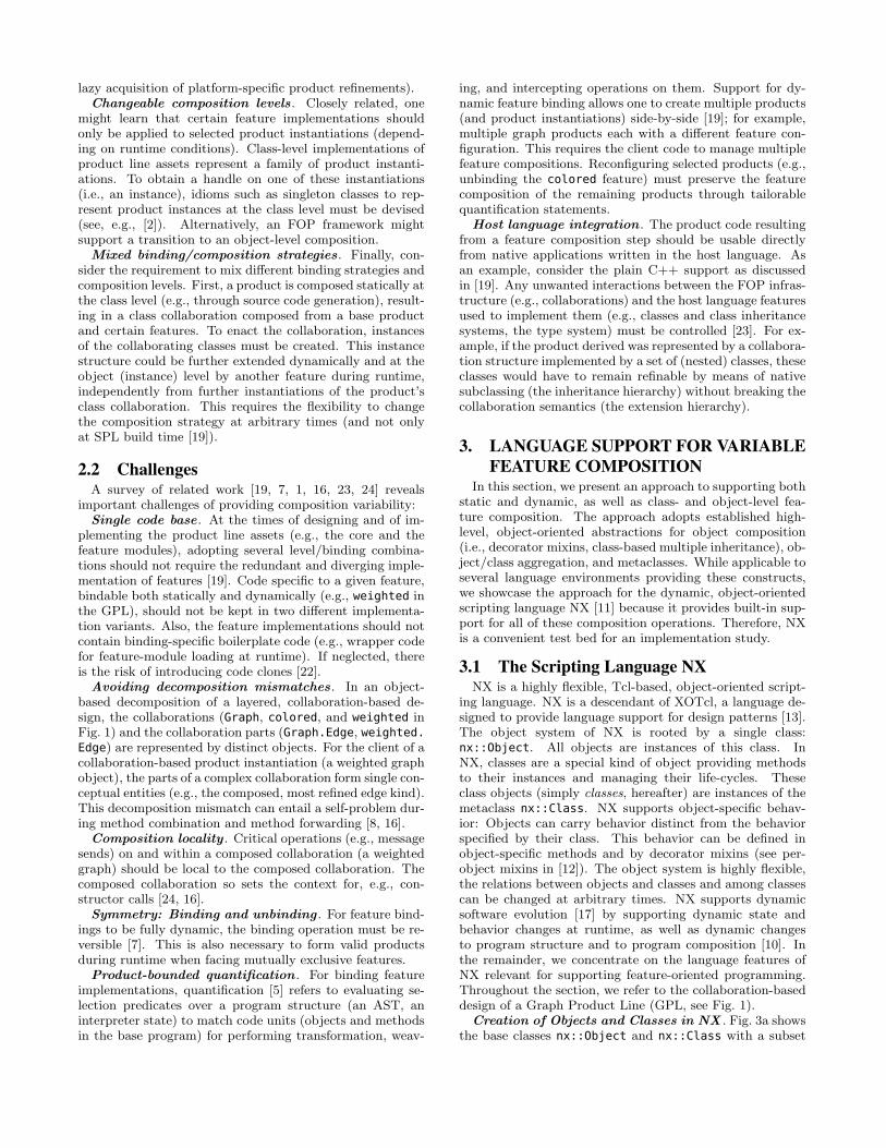
lazy acquisition of platform-specific product refinements).Changeable composition levels. Closely related, one
might learn that certain feature implementations shouldonly be applied to selected product instantiations (depend-ing on runtime conditions). Class-level implementations ofproduct line assets represent a family of product instanti-ations. To obtain a handle on one of these instantiations(i.e., an instance), idioms such as singleton classes to rep-resent product instances at the class level must be devised(see, e.g., [2]). Alternatively, an FOP framework mightsupport a transition to an object-level composition.Mixed binding/composition strategies . Finally, con-
sider the requirement to mix different binding strategies andcomposition levels. First, a product is composed statically atthe class level (e.g., through source code generation), result-ing in a class collaboration composed from a base productand certain features. To enact the collaboration, instancesof the collaborating classes must be created. This instancestructure could be further extended dynamically and at theobject (instance) level by another feature during runtime,independently from further instantiations of the product’sclass collaboration. This requires the flexibility to changethe composition strategy at arbitrary times (and not onlyat SPL build time [19]).
2.2 ChallengesA survey of related work [19, 7, 1, 16, 23, 24] reveals
important challenges of providing composition variability:Single code base . At the times of designing and of im-
plementing the product line assets (e.g., the core and thefeature modules), adopting several level/binding combina-tions should not require the redundant and diverging imple-mentation of features [19]. Code specific to a given feature,bindable both statically and dynamically (e.g., weighted inthe GPL), should not be kept in two different implementa-tion variants. Also, the feature implementations should notcontain binding-specific boilerplate code (e.g., wrapper codefor feature-module loading at runtime). If neglected, thereis the risk of introducing code clones [22].Avoiding decomposition mismatches . In an object-
based decomposition of a layered, collaboration-based de-sign, the collaborations (Graph, colored, and weighted inFig. 1) and the collaboration parts (Graph.Edge, weighted.Edge) are represented by distinct objects. For the client of acollaboration-based product instantiation (a weighted graphobject), the parts of a complex collaboration form single con-ceptual entities (e.g., the composed, most refined edge kind).This decomposition mismatch can entail a self-problem dur-ing method combination and method forwarding [8, 16].Composition locality . Critical operations (e.g., message
sends) on and within a composed collaboration (a weightedgraph) should be local to the composed collaboration. Thecomposed collaboration so sets the context for, e.g., con-structor calls [24, 16].Symmetry: Binding and unbinding . For feature bind-
ings to be fully dynamic, the binding operation must be re-versible [7]. This is also necessary to form valid productsduring runtime when facing mutually exclusive features.Product-bounded quantification . For binding feature
implementations, quantification [5] refers to evaluating se-lection predicates over a program structure (an AST, aninterpreter state) to match code units (objects and methodsin the base program) for performing transformation, weav-
ing, and intercepting operations on them. Support for dy-namic feature binding allows one to create multiple products(and product instantiations) side-by-side [19]; for example,multiple graph products each with a different feature con-figuration. This requires the client code to manage multiplefeature compositions. Reconfiguring selected products (e.g.,unbinding the colored feature) must preserve the featurecomposition of the remaining products through tailorablequantification statements.
Host language integration . The product code resultingfrom a feature composition step should be usable directlyfrom native applications written in the host language. Asan example, consider the plain C++ support as discussedin [19]. Any unwanted interactions between the FOP infras-tructure (e.g., collaborations) and the host language featuresused to implement them (e.g., classes and class inheritancesystems, the type system) must be controlled [23]. For ex-ample, if the product derived was represented by a collabora-tion structure implemented by a set of (nested) classes, theseclasses would have to remain refinable by means of nativesubclassing (the inheritance hierarchy) without breaking thecollaboration semantics (the extension hierarchy).
3. LANGUAGE SUPPORT FOR VARIABLE
FEATURE COMPOSITIONIn this section, we present an approach to supporting both
static and dynamic, as well as class- and object-level fea-ture composition. The approach adopts established high-level, object-oriented abstractions for object composition(i.e., decorator mixins, class-based multiple inheritance), ob-ject/class aggregation, and metaclasses. While applicable toseveral language environments providing these constructs,we showcase the approach for the dynamic, object-orientedscripting language NX [11] because it provides built-in sup-port for all of these composition operations. Therefore, NXis a convenient test bed for an implementation study.
3.1 The Scripting Language NXNX is a highly flexible, Tcl-based, object-oriented script-
ing language. NX is a descendant of XOTcl, a language de-signed to provide language support for design patterns [13].The object system of NX is rooted by a single class:nx::Object. All objects are instances of this class. InNX, classes are a special kind of object providing methodsto their instances and managing their life-cycles. Theseclass objects (simply classes, hereafter) are instances of themetaclass nx::Class. NX supports object-specific behav-ior: Objects can carry behavior distinct from the behaviorspecified by their class. This behavior can be defined inobject-specific methods and by decorator mixins (see per-object mixins in [12]). The object system is highly flexible,the relations between objects and classes and among classescan be changed at arbitrary times. NX supports dynamicsoftware evolution [17] by supporting dynamic state andbehavior changes at runtime, as well as dynamic changesto program structure and to program composition [10]. Inthe remainder, we concentrate on the language features ofNX relevant for supporting feature-oriented programming.Throughout the section, we refer to the collaboration-baseddesign of a Graph Product Line (GPL, see Fig. 1).
Creation of Objects and Classes in NX . Fig. 3a showsthe base classes nx::Object and nx::Class with a subset
47
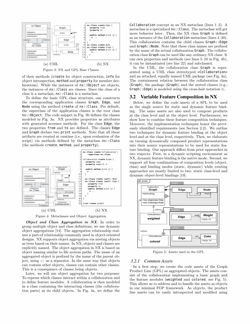
from
Node
«instance»
nx::Class«metaclass»
+create(name)
+info(option)
+method(name,params,body)
+property(spec)
to
Graph
print()
«instance»
Edge
print()
«instance»
edges
nx::Object
new edge(args):Edge
method(name, params, body)
print()
+info(option)
+method(name,params,body)
+property(spec)
(a) UML
1 nx::Class create Edge {
2 :property from
3 :property to
4
5 :public method print {} {
6 # ...
7 }
8 }
9 nx::Class create Node
10 nx::Class create Graph {
11 :public method print {} {
12 # ...
13 }
14 }
(b) NX
Figure 3: NX and GPL Base Classes
of their methods (create for object construction, info forobject introspection, method and property for member dec-larations). While the instances of nx::Object are objects,the instances of nx::Class are classes. Since the class of aclass is a metaclass, nx::Class is a metaclass.To define the basic GPL class structure, one constructs
the corresponding application classes Graph, Edge, andNode using the method create of nx::Class. Per default,the superclass of the application classes is the root classnx::Object. The code snippet in Fig. 3b defines the classesmodeled in Fig. 3a. NX provides properties as attributeswith generated accessor methods. For the class Edge, thetwo properties from and to are defined. The classes Edge
and Graph declare two print methods. Note that all theseartifacts are created at runtime (i.e., upon evaluation of thescript) via methods defined by the metaclass nx::Class
(the methods create, method, and property).
«instance»«instance»
from
Node
to
«instance»
Edge
+print()
edges
Graph
«instance»
«instance»
nx::Object
new edge(args):Edge
method(name, params, body)
print()
+info(option)
+method(name,params,body)
+property(spec)
Collaboration«metaclass»
nx::Class«metaclass»
+create(name)
+info(option)
+method(name,params,body)
+property(spec)
Graph
+print()
«Collaboration»
(a) UML
1 nx::Class create Collaboration \
2 -superclass nx::Class
3
4 Collaboration create Graph {
5 :property name
6 :property edges:0..n
7
8 :public method print {} {
9 # ...
10 }
11
12 nx::Class create [self]::Node
13 nx::Class create [self]::Edge {
14 :property from
15 :property to
16 :public method print {} {
17 # ...
18 }
19 }
20 }
21
22 Graph create graph1
(b) NX
Figure 4: Metaclasses and Object Aggregation
Object and Class Aggregation in NX . In order togroup multiple object and class definitions, we use dynamicobject aggregations [14]. The aggregation relationship real-izes a part-of relationship commonly used in object-orienteddesigns. NX supports object aggregation via nesting objectsas trees based on their names. In NX, objects and classes areexplicitly named. The object aggregation in NX is based onobject naming similar to file system paths: The name of anaggregated object is prefixed by the name of the parent ob-ject, using :: as a separator. In the same way that objectscan contain other objects, classes can contain other classes.This is a consequence of classes being objects.Later, we will use object aggregation for two purposes:
To express which classes interact within a collaboration andto define feature modules. A collaboration is then modeledas a class containing the interacting classes (the collabora-tion parts) as its child objects. In Fig. 4a, we define the
Collaboration concept as an NX metaclass (lines 1–2). Ametaclass is a specialized nx::Class. The metaclass will getmore behavior later. Then, the NX class Graph is definedas an instance of the Collaboration metaclass (lines 4–20).This collaboration contains the child classes Graph::Edge
and Graph::Node. Note that these class names are prefixedby the name of the actual collaboration Graph. The collabo-ration class Graph can be used like any ordinary NX class: Itcan own properties and methods (see lines 5–10 in Fig. 4b),it can be instantiated (see line 22) and subclassed.
In the UML, the collaboration class Graph is repre-sented using a UML class stereotyped «Collaboration»
and an attached, equally named UML package (see Fig. 4a).The containment relation between the collaboration class(Graph), the package (Graph), and the nested classes (e.g.,Graph::Edge) is modeled using the cross-hair notation ⊕.
3.2 Variable Feature Composition in NXBelow, we define the code assets of a SPL to be used
as the single source for static and dynamic feature bind-ing. The same assets are also used to compose productsat the class level and at the object level. Furthermore, weshow how to combine these feature composition techniques.Moreover, the implementation techniques honor the previ-ously identified requirements (see Section 2.2). We outlinetwo techniques for dynamic feature binding at the objectlevel and at the class level, respectively. Then, we elaborateon turning dynamically composed product representationsinto their source representations to be used for static fea-ture binding. Our approach differs from prior approaches intwo respects: First, in a dynamic scripting environment asNX, dynamic feature binding is the native mode. Second, wesupport all four combinations of composition levels (object,class) and binding modes (static, dynamic) while existingapproaches are mostly limited to two: static class-level anddynamic object-level bindings [19].
BaseGraph
Weighted
Graph
EdgeWeight
+value:string
cd: assets
«Collaboration»
«FeatureModule»
edges
+name:string
+new edge(args):Edge
+new node(args):Node
Graph
Weighted
+value:string
«refines»
weightedEdge
Weight
Weighted
EdgeWeight
+value:string
weighted
+value: intEdge
Weight
Weighted
EdgeWeight
+value:string
«FeatureModule» color
colored
+value: int
«refines»
colored
EdgeColor
weight
NodeNode
+from+to
Edge
Figure 5: Assets used in the GPL
3.2.1 Common Assets
In a first step, we create the code assets of the GraphProduct Line (GPL) as aggregated objects. The assets con-sist of the collaboration implementing a basic graph andthe feature modules (weighted and colored; see Fig. 5).This allows us to address and to handle the assets as objectsin our minimal FOP framework. As objects, the productline assets can be easily introspected and modified using
48
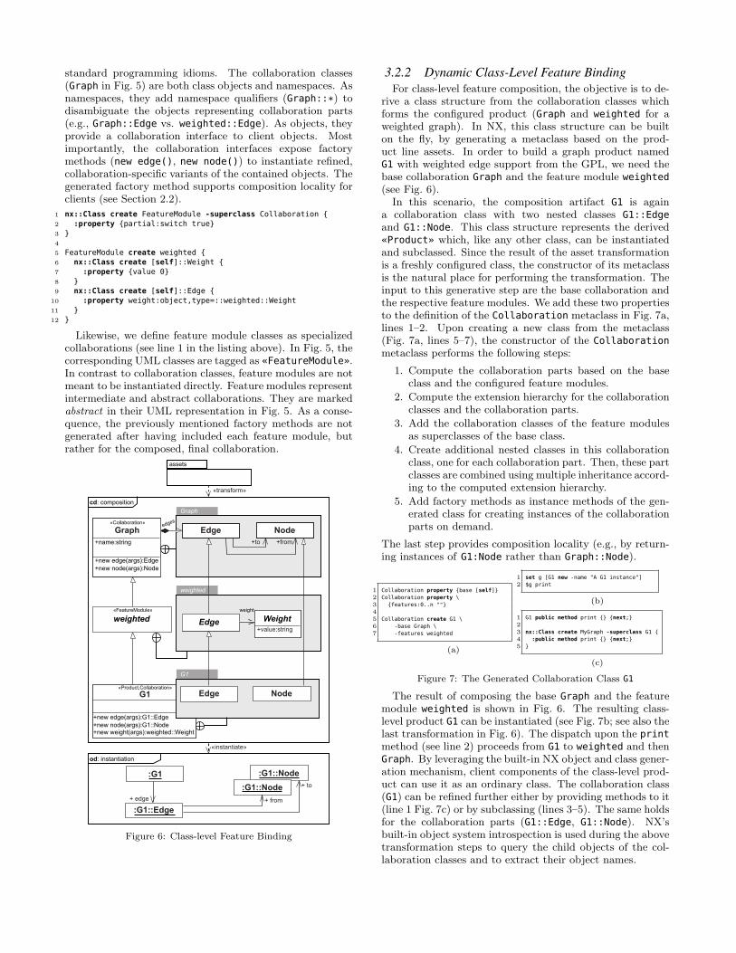
standard programming idioms. The collaboration classes(Graph in Fig. 5) are both class objects and namespaces. Asnamespaces, they add namespace qualifiers (Graph::*) todisambiguate the objects representing collaboration parts(e.g., Graph::Edge vs. weighted::Edge). As objects, theyprovide a collaboration interface to client objects. Mostimportantly, the collaboration interfaces expose factorymethods (new edge(), new node()) to instantiate refined,collaboration-specific variants of the contained objects. Thegenerated factory method supports composition locality forclients (see Section 2.2).
1 nx::Class create FeatureModule -superclass Collaboration {
2 :property {partial:switch true}
3 }
4
5 FeatureModule create weighted {
6 nx::Class create [self]::Weight {
7 :property {value 0}
8 }
9 nx::Class create [self]::Edge {
10 :property weight:object,type=::weighted::Weight
11 }
12 }
Likewise, we define feature module classes as specializedcollaborations (see line 1 in the listing above). In Fig. 5, thecorresponding UML classes are tagged as «FeatureModule».In contrast to collaboration classes, feature modules are notmeant to be instantiated directly. Feature modules representintermediate and abstract collaborations. They are markedabstract in their UML representation in Fig. 5. As a conse-quence, the previously mentioned factory methods are notgenerated after having included each feature module, butrather for the composed, final collaboration.
G1
+new weight(args):weighted::Weight
+new edge(args):G1::Edge
+new node(args):G1::Node
«Product,Collaboration»
G1
Edge Node
cd: composition
od: instantiation
:G1
:G1::Edge
+ edge
:G1::Node
:G1::Node
+ from
+ to
«transform»
«instantiate»
weighted
BaseGraph Node
Weighted Weight
+value:string
«collaboration»
«featureModule»
edges
weight
+name:string
+new edge(args):Edge
+new node(args):Node
Graph
Graph Node
+value:string
«Collaboration»
«FeatureModule»
+name:string
+new edge(args):Edge
+new node(args):Node
weighted WeightEdge
assets
+from+to
Edge
Figure 6: Class-level Feature Binding
3.2.2 Dynamic Class-Level Feature Binding
For class-level feature composition, the objective is to de-rive a class structure from the collaboration classes whichforms the configured product (Graph and weighted for aweighted graph). In NX, this class structure can be builton the fly, by generating a metaclass based on the prod-uct line assets. In order to build a graph product namedG1 with weighted edge support from the GPL, we need thebase collaboration Graph and the feature module weighted(see Fig. 6).
In this scenario, the composition artifact G1 is againa collaboration class with two nested classes G1::Edge
and G1::Node. This class structure represents the derived«Product» which, like any other class, can be instantiatedand subclassed. Since the result of the asset transformationis a freshly configured class, the constructor of its metaclassis the natural place for performing the transformation. Theinput to this generative step are the base collaboration andthe respective feature modules. We add these two propertiesto the definition of the Collaboration metaclass in Fig. 7a,lines 1–2. Upon creating a new class from the metaclass(Fig. 7a, lines 5–7), the constructor of the Collaboration
metaclass performs the following steps:
1. Compute the collaboration parts based on the baseclass and the configured feature modules.
2. Compute the extension hierarchy for the collaborationclasses and the collaboration parts.
3. Add the collaboration classes of the feature modulesas superclasses of the base class.
4. Create additional nested classes in this collaborationclass, one for each collaboration part. Then, these partclasses are combined using multiple inheritance accord-ing to the computed extension hierarchy.
5. Add factory methods as instance methods of the gen-erated class for creating instances of the collaborationparts on demand.
The last step provides composition locality (e.g., by return-ing instances of G1:Node rather than Graph::Node).
1 Collaboration property {base [self]}
2 Collaboration property \
3 {features:0..n ""}
4
5 Collaboration create G1 \
6 -base Graph \
7 -features weighted
(a)
1 set g [G1 new -name "A G1 instance"]
2 $g print
(b)
1 G1 public method print {} {next;}
2
3 nx::Class create MyGraph -superclass G1 {
4 :public method print {} {next;}
5 }
(c)
Figure 7: The Generated Collaboration Class G1
The result of composing the base Graph and the featuremodule weighted is shown in Fig. 6. The resulting class-level product G1 can be instantiated (see Fig. 7b; see also thelast transformation in Fig. 6). The dispatch upon the printmethod (see line 2) proceeds from G1 to weighted and thenGraph. By leveraging the built-in NX object and class gener-ation mechanism, client components of the class-level prod-uct can use it as an ordinary class. The collaboration class(G1) can be refined further either by providing methods to it(line 1 Fig. 7c) or by subclassing (lines 3–5). The same holdsfor the collaboration parts (G1::Edge, G1::Node). NX’sbuilt-in object system introspection is used during the abovetransformation steps to query the child objects of the col-laboration classes and to extract their object names.
49
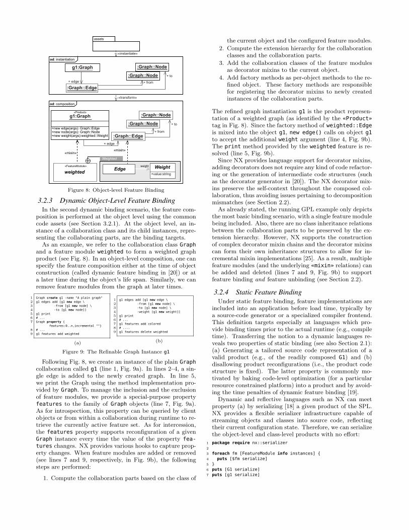
od: instantiation
g1:Graph
:Graph::Edge
+ edge
:Graph::Node
+ from
+ to
od: composition
g1:Graph
:Graph::Edge
+ edge
+ from
+ to
«mixin»«mixin»
«transform»
Weighted
Edge Weight
+value:string
«FeatureModule» weight
+new weight(args):weighted::Weight
+value:string
«Product»
weightedWeightEdge
:Graph::Node
:Graph::Node
:Graph::Node+new edge(args): Graph::Edge+new node(args): Graph::Node
«instantiate»
assets
Figure 8: Object-level Feature Binding
3.2.3 Dynamic Object-Level Feature Binding
In the second dynamic binding scenario, the feature com-position is performed at the object level using the commoncode assets (see Section 3.2.1). At the object level, an in-stance of a collaboration class and its child instances, repre-senting the collaborating parts, are the binding targets.As an example, we refer to the collaboration class Graph
and a feature module weighted to form a weighted graphproduct (see Fig. 8). In an object-level composition, one canspecify the feature composition either at the time of objectconstruction (called dynamic feature binding in [20]) or ata later time during the object’s life span. Similarly, we canremove feature modules from the graph at later times.
1 Graph create g1 -name "A plain graph"
2 g1 edges add [g1 new edge \
3 -from [g1 new node] \
4 -to [g1 new node]]
5 g1 print
6 # ...
7 Graph property {
features:0..n,incremental ""}
8 # ...
9 g1 features add weighted
(a)
1 g1 edges add [g1 new edge \
2 -from [g1 new node] \
3 -to [g1 new node] \
4 -weight [g1 new weight]]
5 g1 print
6 # ...
7 g1 features add colored
8 # ....
9 g1 features delete weighted
(b)
Figure 9: The Refinable Graph Instance g1
Following Fig. 8, we create an instance of the plain Graph
collaboration called g1 (line 1, Fig. 9a). In lines 2–4, a sin-gle edge is added to the newly created graph. In line 5,we print the Graph using the method implementation pro-vided by Graph. To manage the inclusion and the exclusionof feature modules, we provide a special-purpose propertyfeatures to the family of Graph objects (line 7, Fig. 9a).As for introspection, this property can be queried by clientobjects or from within a collaboration during runtime to re-trieve the currently active feature set. As for intercession,the features property supports reconfiguration of a givenGraph instance every time the value of the property fea-
tures changes. NX provides various hooks to capture prop-erty changes. When feature modules are added or removed(see lines 7 and 9, respectively, in Fig. 9b), the followingsteps are performed:
1. Compute the collaboration parts based on the class of
the current object and the configured feature modules.
2. Compute the extension hierarchy for the collaborationclasses and the collaboration parts.
3. Add the collaboration classes of the feature modulesas decorator mixins to the current object.
4. Add factory methods as per-object methods to the re-fined object. These factory methods are responsiblefor registering the decorator mixins to newly createdinstances of the collaboration parts.
The refined graph instantiation g1 is the product represen-tation of a weighted graph (as identified by the «Product»
tag in Fig. 8). Since the factory method of weighted::Edgeis mixed into the object g1, new edge() calls on object g1to accept the additional weight argument (line 4, Fig. 9b).The print method provided by the weighted feature is re-solved (line 5, Fig. 9b).
Since NX provides language support for decorator mixins,adding decorators does not require any kind of code refactor-ing or the generation of intermediate code structures (suchas the decorator generator in [20]). The NX decorator mix-ins preserve the self-context throughout the composed col-laboration, thus avoiding issues pertaining to decompositionmismatches (see Section 2.2).
As already stated, the running GPL example only depictsthe most basic binding scenario, with a single feature modulebeing included. Also, there are no class inheritance relationsbetween the collaboration parts to be preserved by the ex-tension hierarchy. However, NX supports the constructionof complex decorator mixin chains and the decorator mixinscan form their own inheritance structures to allow for in-cremental mixin implementations [25]. As a result, multiplefeature modules (and the underlying «mixin» relations) canbe added and deleted (lines 7 and 9, Fig. 9b) to supportfeature binding and feature unbinding (see Section 2.2).
3.2.4 Static Feature Binding
Under static feature binding, feature implementations areincluded into an application before load time, typically bya source-code generator or a specialized compiler frontend.This definition targets especially at languages which pro-vide binding times prior to the actual runtime (e.g., compiletime). Transferring the notion to a dynamic languages re-veals two properties of static binding (see also Section 2.1):(a) Generating a tailored source code representation of avalid product (e.g., of the readily composed G1) and (b)disallowing product reconfigurations (i.e., the product codestructure is fixed). The latter property is commonly mo-tivated by baking code-level optimization (for a particularresource constrained platform) into a product and by avoid-ing the time penalties of dynamic feature binding [19].
Dynamic and reflective languages such as NX can meetproperty (a) by serializing [18] a given product of the SPL.NX provides a flexible serializer infrastructure capable ofstreaming objects and classes into source code, reflectingtheir current configuration state. Therefore, we can serializethe object-level and class-level products with no effort:
1 package require nx::serializer
2
3 foreach fm [FeatureModule info instances] {
4 puts [$fm serialize]
5 }
6 puts [G1 serialize]
7 puts [g1 serialize]
50
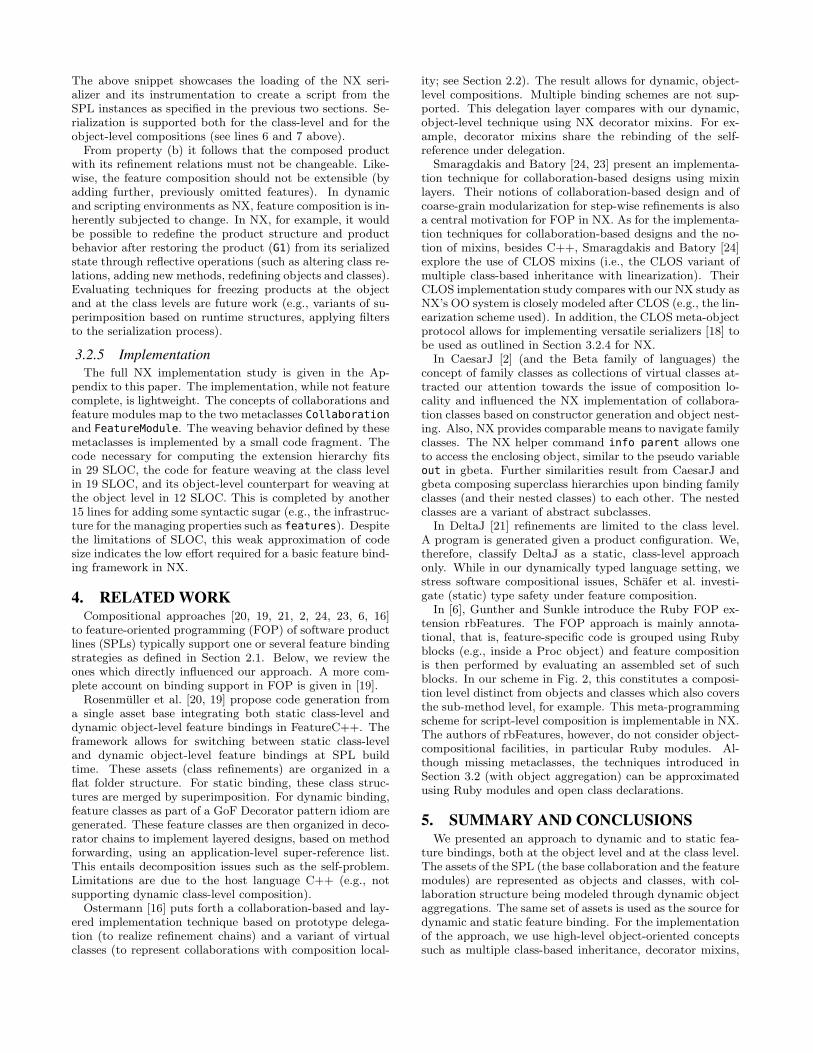
The above snippet showcases the loading of the NX seri-alizer and its instrumentation to create a script from theSPL instances as specified in the previous two sections. Se-rialization is supported both for the class-level and for theobject-level compositions (see lines 6 and 7 above).From property (b) it follows that the composed product
with its refinement relations must not be changeable. Like-wise, the feature composition should not be extensible (byadding further, previously omitted features). In dynamicand scripting environments as NX, feature composition is in-herently subjected to change. In NX, for example, it wouldbe possible to redefine the product structure and productbehavior after restoring the product (G1) from its serializedstate through reflective operations (such as altering class re-lations, adding new methods, redefining objects and classes).Evaluating techniques for freezing products at the objectand at the class levels are future work (e.g., variants of su-perimposition based on runtime structures, applying filtersto the serialization process).
3.2.5 Implementation
The full NX implementation study is given in the Ap-pendix to this paper. The implementation, while not featurecomplete, is lightweight. The concepts of collaborations andfeature modules map to the two metaclasses Collaborationand FeatureModule. The weaving behavior defined by thesemetaclasses is implemented by a small code fragment. Thecode necessary for computing the extension hierarchy fitsin 29 SLOC, the code for feature weaving at the class levelin 19 SLOC, and its object-level counterpart for weaving atthe object level in 12 SLOC. This is completed by another15 lines for adding some syntactic sugar (e.g., the infrastruc-ture for the managing properties such as features). Despitethe limitations of SLOC, this weak approximation of codesize indicates the low effort required for a basic feature bind-ing framework in NX.
4. RELATED WORKCompositional approaches [20, 19, 21, 2, 24, 23, 6, 16]
to feature-oriented programming (FOP) of software productlines (SPLs) typically support one or several feature bindingstrategies as defined in Section 2.1. Below, we review theones which directly influenced our approach. A more com-plete account on binding support in FOP is given in [19].Rosenmuller et al. [20, 19] propose code generation from
a single asset base integrating both static class-level anddynamic object-level feature bindings in FeatureC++. Theframework allows for switching between static class-leveland dynamic object-level feature bindings at SPL buildtime. These assets (class refinements) are organized in aflat folder structure. For static binding, these class struc-tures are merged by superimposition. For dynamic binding,feature classes as part of a GoF Decorator pattern idiom aregenerated. These feature classes are then organized in deco-rator chains to implement layered designs, based on methodforwarding, using an application-level super-reference list.This entails decomposition issues such as the self-problem.Limitations are due to the host language C++ (e.g., notsupporting dynamic class-level composition).Ostermann [16] puts forth a collaboration-based and lay-
ered implementation technique based on prototype delega-tion (to realize refinement chains) and a variant of virtualclasses (to represent collaborations with composition local-
ity; see Section 2.2). The result allows for dynamic, object-level compositions. Multiple binding schemes are not sup-ported. This delegation layer compares with our dynamic,object-level technique using NX decorator mixins. For ex-ample, decorator mixins share the rebinding of the self-reference under delegation.
Smaragdakis and Batory [24, 23] present an implementa-tion technique for collaboration-based designs using mixinlayers. Their notions of collaboration-based design and ofcoarse-grain modularization for step-wise refinements is alsoa central motivation for FOP in NX. As for the implementa-tion techniques for collaboration-based designs and the no-tion of mixins, besides C++, Smaragdakis and Batory [24]explore the use of CLOS mixins (i.e., the CLOS variant ofmultiple class-based inheritance with linearization). TheirCLOS implementation study compares with our NX study asNX’s OO system is closely modeled after CLOS (e.g., the lin-earization scheme used). In addition, the CLOS meta-objectprotocol allows for implementing versatile serializers [18] tobe used as outlined in Section 3.2.4 for NX.
In CaesarJ [2] (and the Beta family of languages) theconcept of family classes as collections of virtual classes at-tracted our attention towards the issue of composition lo-cality and influenced the NX implementation of collabora-tion classes based on constructor generation and object nest-ing. Also, NX provides comparable means to navigate familyclasses. The NX helper command info parent allows oneto access the enclosing object, similar to the pseudo variableout in gbeta. Further similarities result from CaesarJ andgbeta composing superclass hierarchies upon binding familyclasses (and their nested classes) to each other. The nestedclasses are a variant of abstract subclasses.
In DeltaJ [21] refinements are limited to the class level.A program is generated given a product configuration. We,therefore, classify DeltaJ as a static, class-level approachonly. While in our dynamically typed language setting, westress software compositional issues, Schafer et al. investi-gate (static) type safety under feature composition.
In [6], Gunther and Sunkle introduce the Ruby FOP ex-tension rbFeatures. The FOP approach is mainly annota-tional, that is, feature-specific code is grouped using Rubyblocks (e.g., inside a Proc object) and feature compositionis then performed by evaluating an assembled set of suchblocks. In our scheme in Fig. 2, this constitutes a composi-tion level distinct from objects and classes which also coversthe sub-method level, for example. This meta-programmingscheme for script-level composition is implementable in NX.The authors of rbFeatures, however, do not consider object-compositional facilities, in particular Ruby modules. Al-though missing metaclasses, the techniques introduced inSection 3.2 (with object aggregation) can be approximatedusing Ruby modules and open class declarations.
5. SUMMARY AND CONCLUSIONSWe presented an approach to dynamic and to static fea-
ture bindings, both at the object level and at the class level.The assets of the SPL (the base collaboration and the featuremodules) are represented as objects and classes, with col-laboration structure being modeled through dynamic objectaggregations. The same set of assets is used as the source fordynamic and static feature binding. For the implementationof the approach, we use high-level object-oriented conceptssuch as multiple class-based inheritance, decorator mixins,
51
metaclasses, object/class aggregation, and object system in-trospection. The resulting implementation study meets crit-ical requirements, such as providing for a single code base,composition locality, and the avoidance of typical decom-position mismatches in collaboration-based designs. Givenappropriate language support as in NX, the approach turnsinto a lightweight implementation (see the Appendix).The approach presented is not complete. We have not
addressed checking of product line models, evaluating com-position constraints (unlike [19]), and handling feature in-teractions. Also, support for homogeneous and dynamicallycrosscutting features has not been considered. For the latter,NX provides message-level filters [13]. NX also supports con-ditional mixins for fine-grained composition control, basedon guarding expressions. There are also mixin variants [25]available to enforce strict feature ordering. Besides, whilethe GPL helps demonstrate similarities and differences toprior work [20, 16], the framework’s fit regarding larger-scaleSPLs remains to be evaluated.In a next step, we will extend our feature binding frame-
work beyond structure-preserving binding techniques tosupport flattening layered collaboration structures (see themerge operator in [15] and traits [4]). This is important tooffer optimizations (e.g., minimizing a product’s memoryfootprint) under both the static and the dynamic bindingmodes, as well as to fully support static feature binding.
6. REFERENCES
[1] S. Apel, D. S. Batory, and M. Rosenmuller. On theStructure of Crosscutting Concerns: Using Aspects orCollaborations? In Proc. Workshop Aspect-OrientedProduct Line Eng. (AOPLE), 2006.
[2] I. Aracic, V. Gasiunas, M. Mezini, and K. Ostermann.An overview of CaesarJ. T. Aspect-Oriented SoftwareDevelop. I, pages 135–173, 2006.
[3] K. Czarnecki and U. W. Eisenecker. GenerativeProgramming — Methods, Tools, and Applications.Addison-Wesley, 6th edition, 2000.
[4] S. Ducasse, O. Nierstrasz, N. Scharli, R. Wuyts, andA. P. Black. Traits: A Mechanism for Fine-grainedReuse. ACM Trans. Program. Lang. Syst.,28(2):331–388, 2006.
[5] R. E. Filman, T. Elrad, S. Clarke, and M. Aksit.Aspect-Oriented Programming is Quantification andObliviousness. In Aspect-Oriented SoftwareDevelopment, chapter 2. Addison-Wesley, Oct 2004.
[6] S. Gunther and S. Sunkle. rbFeatures:Feature-oriented programming with Ruby. Sci.Comput. Program., 77(3):152 –173, 2012.
[7] S. O. Hallsteinsen, M. Hinchey, S. Park, andK. Schmid. Dynamic software product lines. IEEEComputer, 41(4):93–95, 2008.
[8] H. Lieberman. Using Prototypical Objects toImplement Shared Behavior in Object-orientedSystems. SIGPLAN Not., 21(11):214–223, June 1986.
[9] R. E. Lopez-Herrejon, D. S. Batory, and W. R. Cook.Evaluating Support for Features in AdvancedModularization Technologies. In Proc. 19th Europ.Conf. Object-Oriented Programming (ECOOP’05),volume 3586 of LNCS, pages 169–194. Springer, 2005.
[10] G. Neumann. Dynamic Software Evolution in theNext Scripting Language. http://next-
scripting.org/docs/2.0b3/doc/nx/nx-code-evolution/,last accessed on July 9th, 2012, July 2012.
[11] G. Neumann and S. Sobernig. An Overview of theNext Scripting Toolkit. In Proc. 18th Annu. Tcl/TkConf. Tcl Association, 2011.
[12] G. Neumann and U. Zdun. Enhancing Object-BasedSystem Composition through Per-Object Mixins. InProc. Asia-Pacific Software Eng. Conf. (APSEC’99),pages 522–530. IEEE Computer Society, 1999.
[13] G. Neumann and U. Zdun. Filters as a LanguageSupport for Design Patterns in Object-OrientedScripting Languages. In Proc. 5th Conf.Object-Oriented Technologies and Syst. (COOTS’99).USENIX, 1999.
[14] G. Neumann and U. Zdun. Towards the Usage ofDynamic Object Aggregation as a Foundation forComposition. In Proc. Symp. Applied Computing(SAC’00), pages 818–821. ACM, 2000.
[15] H. Ossher and W. Harrison. Combination ofInheritance Hierarchies. In Conf. Proc. Object-orientedProgramming Syst., Languages and Applicat.(OOPSLA’92), pages 25–40. ACM, 1992.
[16] K. Ostermann. Dynamically ComposableCollaborations with Delegation Layers. In Proc. 16thEurop. Conf. Object-Oriented Programming(ECOOP’02), pages 89–110. Springer, 2002.
[17] S. Rank. A Reflective Architecture to SupportDynamic Software Evolution. PhD thesis, Universityof Durham, UK, 2002.
[18] D. Riehle, W. Siberski, D. Baumer, D. Megert, andH. Zullighoven. Serializer. In Pattern Languages ofProgram Design 3, pages 293–312. Addison-Wesley,1998.
[19] M. Rosenmuller, N. Siegmund, S. Apel, and G. Saake.Flexible feature binding in software product lines.Autom. Softw. Eng., 18:163–197, 2011.
[20] M. Rosenmuller, N. Siegmund, G. Saake, and S. Apel.Code generation to support static and dynamiccomposition of software product lines. In Proc. 7thInt. Conf. Generative Programming and ComponentEng. (GPCE’08), pages 3–12. ACM, 2008.
[21] I. Schaefer, L. Bettini, and F. Damiani. Delta-orientedProgramming of Software Product Lines. In Proc. 10thInt. Conf. Aspect-oriented Software Develop., pages43–56. ACM, 2011.
[22] S. Schulze, S. Apel, and C. Kastner. Code Clones inFeature-Oriented Software Product Lines. In Proc. 9thInt. Conf. Generative Programming and ComponentEng. (GPCE’10), pages 103–112. ACM, 2010.
[23] Y. Smaragdakis and D. Batory. Mixin Layers: AnObject-Oriented Implementation Technique forRefinements and Collaboration-Based Designs. ACMT. Softw. Eng. Meth., 11(2):215–255, 2002.
[24] Y. Smaragdakis and D. S. Batory. Implementinglayered designs with mixin layers. In Proc. 12th Europ.Conf. Object-Oriented Programming (ECOOP’98),pages 550–570. Springer, 1998.
[25] U. Zdun, M. Strembeck, and G. Neumann.Object-based and class-based composition of transitivemixins. Inform. Software Techn., 49(8):871–891, 2007.
52
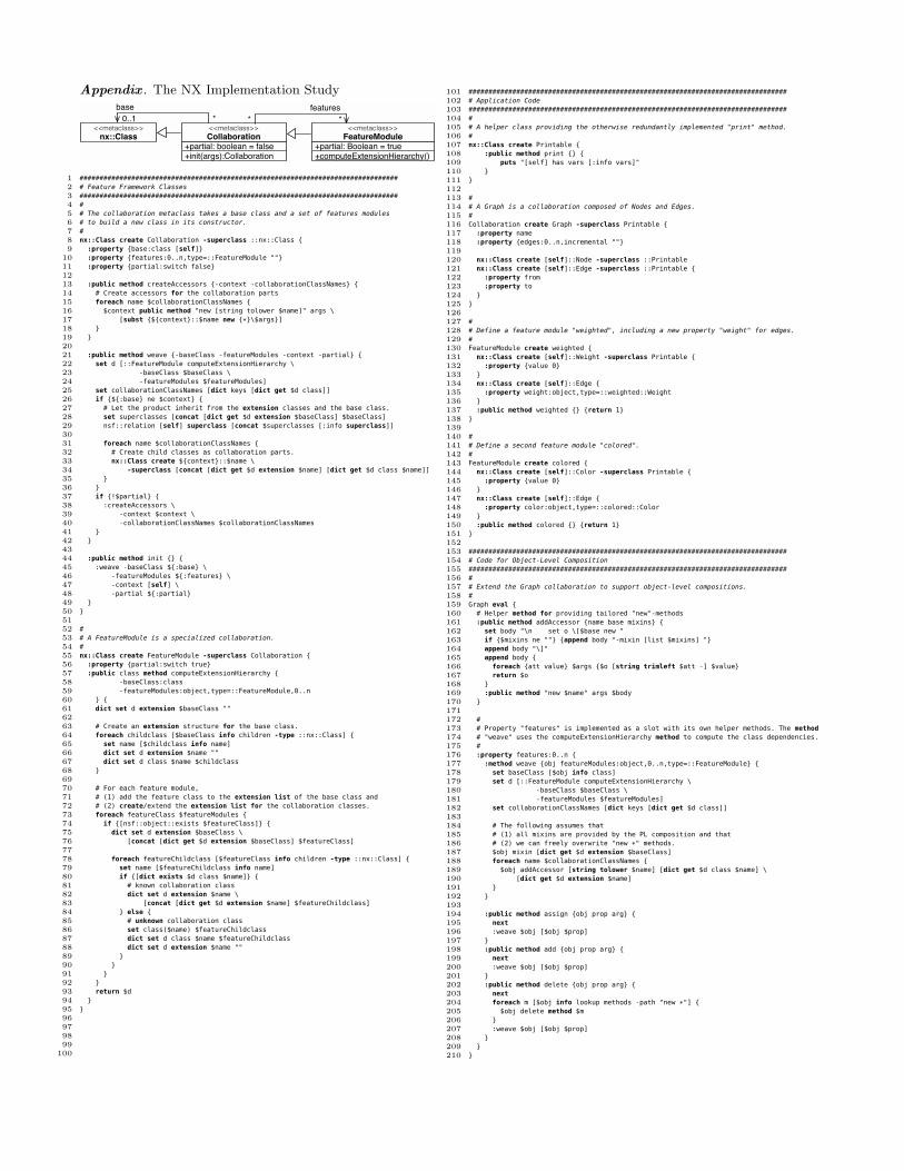
Appendix . The NX Implementation Study
<<metaclass>>
nx::Class
+init(args):Collaboration+partial: boolean = false
<<metaclass>>
Collaboration
+computeExtensionHierarchy()+partial: Boolean = true
<<metaclass>>
FeatureModule
base
0..1 *
features
**
1 ################################################################################
2 # Feature Framework Classes
3 ################################################################################
4 #
5 # The collaboration metaclass takes a base class and a set of features modules
6 # to build a new class in its constructor.
7 #
8 nx::Class create Collaboration -superclass ::nx::Class {
9 :property {base:class [self]}
10 :property {features:0..n,type=::FeatureModule ""}
11 :property {partial:switch false}
12
13 :public method createAccessors {-context -collaborationClassNames} {
14 # Create accessors for the collaboration parts
15 foreach name $collaborationClassNames {
16 $context public method "new [string tolower $name]" args \
17 [subst {${context}::$name new {*}\$args}]
18 }
19 }
20
21 :public method weave {-baseClass -featureModules -context -partial} {
22 set d [::FeatureModule computeExtensionHierarchy \
23 -baseClass $baseClass \
24 -featureModules $featureModules]
25 set collaborationClassNames [dict keys [dict get $d class]]
26 if {${:base} ne $context} {
27 # Let the product inherit from the extension classes and the base class.
28 set superclasses [concat [dict get $d extension $baseClass] $baseClass]
29 nsf::relation [self] superclass [concat $superclasses [:info superclass]]
30
31 foreach name $collaborationClassNames {
32 # Create child classes as collaboration parts.
33 nx::Class create ${context}::$name \
34 -superclass [concat [dict get $d extension $name] [dict get $d class $name]]
35 }
36 }
37 if {!$partial} {
38 :createAccessors \
39 -context $context \
40 -collaborationClassNames $collaborationClassNames
41 }
42 }
43
44 :public method init {} {
45 :weave -baseClass ${:base} \
46 -featureModules ${:features} \
47 -context [self] \
48 -partial ${:partial}
49 }
50 }
51
52 #
53 # A FeatureModule is a specialized collaboration.
54 #
55 nx::Class create FeatureModule -superclass Collaboration {
56 :property {partial:switch true}
57 :public class method computeExtensionHierarchy {
58 -baseClass:class
59 -featureModules:object,type=::FeatureModule,0..n
60 } {
61 dict set d extension $baseClass ""
62
63 # Create an extension structure for the base class.
64 foreach childclass [$baseClass info children -type ::nx::Class] {
65 set name [$childclass info name]
66 dict set d extension $name ""
67 dict set d class $name $childclass
68 }
69
70 # For each feature module,
71 # (1) add the feature class to the extension list of the base class and
72 # (2) create/extend the extension list for the collaboration classes.
73 foreach featureClass $featureModules {
74 if {[nsf::object::exists $featureClass]} {
75 dict set d extension $baseClass \
76 [concat [dict get $d extension $baseClass] $featureClass]
77
78 foreach featureChildclass [$featureClass info children -type ::nx::Class] {
79 set name [$featureChildclass info name]
80 if {[dict exists $d class $name]} {
81 # known collaboration class
82 dict set d extension $name \
83 [concat [dict get $d extension $name] $featureChildclass]
84 } else {
85 # unknown collaboration class
86 set class($name) $featureChildclass
87 dict set d class $name $featureChildclass
88 dict set d extension $name ""
89 }
90 }
91 }
92 }
93 return $d
94 }
95 }
96
97
98
99
100
101 ################################################################################
102 # Application Code
103 ################################################################################
104 #
105 # A helper class providing the otherwise redundantly implemented "print" method.
106 #
107 nx::Class create Printable {
108 :public method print {} {
109 puts "[self] has vars [:info vars]"
110 }
111 }
112
113 #
114 # A Graph is a collaboration composed of Nodes and Edges.
115 #
116 Collaboration create Graph -superclass Printable {
117 :property name
118 :property {edges:0..n,incremental ""}
119
120 nx::Class create [self]::Node -superclass ::Printable
121 nx::Class create [self]::Edge -superclass ::Printable {
122 :property from
123 :property to
124 }
125 }
126
127 #
128 # Define a feature module "weighted", including a new property "weight" for edges.
129 #
130 FeatureModule create weighted {
131 nx::Class create [self]::Weight -superclass Printable {
132 :property {value 0}
133 }
134 nx::Class create [self]::Edge {
135 :property weight:object,type=::weighted::Weight
136 }
137 :public method weighted {} {return 1}
138 }
139
140 #
141 # Define a second feature module "colored".
142 #
143 FeatureModule create colored {
144 nx::Class create [self]::Color -superclass Printable {
145 :property {value 0}
146 }
147 nx::Class create [self]::Edge {
148 :property color:object,type=::colored::Color
149 }
150 :public method colored {} {return 1}
151 }
152
153 ################################################################################
154 # Code for Object-Level Composition
155 ################################################################################
156 #
157 # Extend the Graph collaboration to support object-level compositions.
158 #
159 Graph eval {
160 # Helper method for providing tailored "new"-methods
161 :public method addAccessor {name base mixins} {
162 set body "\n set o \[$base new "
163 if {$mixins ne ""} {append body "-mixin [list $mixins] "}
164 append body "\]"
165 append body {
166 foreach {att value} $args {$o [string trimleft $att -] $value}
167 return $o
168 }
169 :public method "new $name" args $body
170 }
171
172 #
173 # Property "features" is implemented as a slot with its own helper methods. The method
174 # "weave" uses the computeExtensionHierarchy method to compute the class dependencies.
175 #
176 :property features:0..n {
177 :method weave {obj featureModules:object,0..n,type=::FeatureModule} {
178 set baseClass [$obj info class]
179 set d [::FeatureModule computeExtensionHierarchy \
180 -baseClass $baseClass \
181 -featureModules $featureModules]
182 set collaborationClassNames [dict keys [dict get $d class]]
183
184 # The following assumes that
185 # (1) all mixins are provided by the PL composition and that
186 # (2) we can freely overwrite "new *" methods.
187 $obj mixin [dict get $d extension $baseClass]
188 foreach name $collaborationClassNames {
189 $obj addAccessor [string tolower $name] [dict get $d class $name] \
190 [dict get $d extension $name]
191 }
192 }
193
194 :public method assign {obj prop arg} {
195 next
196 :weave $obj [$obj $prop]
197 }
198 :public method add {obj prop arg} {
199 next
200 :weave $obj [$obj $prop]
201 }
202 :public method delete {obj prop arg} {
203 next
204 foreach m [$obj info lookup methods -path "new *"] {
205 $obj delete method $m
206 }
207 :weave $obj [$obj $prop]
208 }
209 }
210 }
53
Safe Adaptation in Context-Aware Feature Models
Fabiana G. Marinho,Department of Computer
ScienceFederal University of Ceará
Fortaleza, [email protected]
Rossana M. C. AndradeDepartment of Computer
ScienceFederal University of Ceará
Fortaleza, [email protected]
Paulo A. S. CostaDepartment of Computer
ScienceFederal University of Ceará
Fortaleza, [email protected]
Paulo H. M. MaiaGroup of Computer Network,
Software Engineering andSystems - GREat
Federal University of CearáFortaleza, Brazil
Vania M. P. VidalDepartment of Computer
ScienceFederal University of Ceará
Fortaleza, [email protected]
Claudia WernerSystems Engineering and
Computer Science ProgramFederal University of Rio de
JaneiroRio de Janeiro, Brazil
ABSTRACTSoftware product lines, usually described using feature mod-els, have proven to be a feasible solution to develop mobileand context-aware applications. These applications use con-text information to provide services and data for their usersfrom anywhere and at any time. However, building fea-ture models for mobile and context-aware software productlines demands advanced skills of software engineers, sinceit comprises system and context information. Moreover,to guarantee a correct application execution, these mod-els must be thoroughly specified, composed and verified tocheck whether some composition and adaptation rules areviolated. Although this is an important task, there is a lackof formalization of such rules, which makes it difficult to usethose rules for feature models verification. In this paper,we propose an approach to prevent defects in context-awarefeature models and in their product reconfiguration basedon formal methods. To validate our work, we developed aprototype to check the correctness of context-aware featuremodels.
Categories and Subject DescriptorsD. SOFTWARE [D.2. SOFTWARE ENGINEERING]:D.2.4 Software/Program Verification—Assertion checkers,Correctness proofs, Formal methods
General TermsVerification
Permission to make digital or hard copies of all or part of this work forpersonal or classroom use is granted without fee provided that copies arenot made or distributed for profit or commercial advantage and that copiesbear this notice and the full citation on the first page. To copy otherwise, torepublish, to post on servers or to redistribute to lists, requires prior specificpermission and/or a fee.FOSD’12, September 24–25, 2012, Dresden, Germany.Copyright 2012 ACM 978-1-4503-1309-4/12/09 ...$15.00.
KeywordsContext-Aware SPL, Feature Model, Formal Method
1. INTRODUCTIONSoftware Product Line Engineering (SPLE) is a reuse-
driven development paradigm which heavily relies on do-main analysis to identify variabilities to manage the dif-ferences between products. To accomplish this, SPL ap-proaches use, in many cases, Feature Models (FMs) [18],which describe a domain by representing common and vari-able features of an SPL.
Technological advances in mobile devices are fostering thecreation of highly distributed and interactive applications,characterized by the dynamicity and uncertainness of re-sources. In these applications, requirements such as mobil-ity and context-awareness demand interoperable, uncoupled,adaptable, and autonomous programming abstractions [21].Thus, at runtime, the environment, user requirements andinterfaces between software and hardware may change dy-namically, requiring a prompt response to these changes [17].
SPLs have shown to be an efficient way to handle require-ments from mobile and context-awareness domain, as can befound in [17], [19], and [23]. In that direction, an SPL to sup-port the development of context-aware applications, calledContext-Aware Software Product Line (CASPL), shouldrepresent in the FM the context information relevant to thedomain and describe the impact of this context informationon the product adaptation.
Throughout this paper, FMs for CASPLs are called Con-text -Aware Feature Models (CAFMs) and are composed bytwo models: a System Model (SM), which expresses vari-abilities and similarities between features of the modeleddomain, and a Context Model (CM), which represents con-text entities of that domain. These models are enrichedby Composition Rules (CR) and Adaptation Rules (AR).The former specifies constraints among SM elements only,while the latter defines relationships among elements of thetwo models, such as which context information in a CMcan cause an adaptation in a SM . Here, well-formednessis understood as the conformance of model elements withconstraints of the underlying formal specification. Observe
54
that well-formedness and consistency go beyond syntacticalcorrectness, as they also take into account semantic con-straints. Ensuring that all participating models and rulesin a CAFM are well-formed and consistent is necessary,but not sufficient to ensure a safe adaptation, since adapta-tion problems can occur only to a particular reconfigurationcreated at runtime. Considering this scenario, to guaran-tee those properties, the models that comprise a CAFMshould be composed to verify the lack of defects, which rep-resent violations of the specified rules. However, analyzingthese potential defects is a challenging task, since ensuringthat relevant properties and constrains are preserved duringcomposition is essential. Therefore, a verification mecha-nism should be proposed to check the presence of defectsthat can emerge from SM and CM composition.
The main contribution of this paper is to propose an ap-proach that aims at minimizing the presence of defects inproduct adaptation by predicting, at development time, thedefects that may arise in a CAFM . This approach usesa specification that formalize CAFM elements and proper-ties. To validate the proposed approach, we have developeda prototype with which the user can model CAFMs thatwill be automatically and transparently translated into aninternal formal specification. The tool uses this new modelrepresentation to verify its well-formedness and consistencyagainst a set of predefined properties. Therefore, the userdoes not need to know and deal with the formal specifica-tion.
The remainder of this paper is divided as follows. In Sec-tion 2, we discuss work related to the proposed approach. InSection 3, we present and formalize the concepts related toCAFM. In Section 4, we present the properties that corre-spond to the set of formal requirements for rules in a CAFM.In Section 5, we present our approach. In Section 6, we use aprototype to validate the proposed approach, and finally, inSection 7, we present our conclusions and future directions.
2. RELATED WORKWe structure our discussion of related work into three
categories: analysis of FMs, modeling and well-formednesschecking of CAFMs, and proposals to maximize integrity ofmodel composition. Regarding the former category, Zaid etal. [28] and Wang et al. [27] propose an ontology in order toformalize FMs to check model consistency and conflict de-tection through predefined rules. Czarnecki and Pietroszekused Object Constraint Language (OCL) to validate con-straint rules in [10]. Sun et al. [25] propose the use of Alloyto formalize FMs and the Alloy Analyzer tool to check FMsconsistency. Gheyi et al. [16] also adopt Alloy and AlloyAnalyzer to propose a generic formalization and consistencychecking to FMs.
Other approaches check the consistency of FMs based onrigorous mathematical theories. For example, Zhang et al.[29], Mannion [22] and Batory [4] propose FM translationinto propositional formulas. Czarnecki and Wasowski [11]propose the extraction of FMs from propositional formulas.The use of constraint programming is investigated by Be-navides [5] and Trinidad et al. [1]. According to Benavides[5], the main disadvantage in those proposals is the low levelof abstraction used, since they are only appropriated whenFMs are analyzed using the specific formalisms and toolsto each proposal. Moreover, the support for the analysis ofextended FMs and CAFMs is flawed in most of the afore-
mentioned studies.In the second category, there are research work in the liter-
ature that address context modeling and correctness check-ing during variability modeling. For example, Fernandeset al. [15] propose a notation for variability modeling forcontext-aware SPLs, called UBIFEX-Notation. The authorsalso propose the UBIFEX-Simulation to minimize defects inthe configured CAFM. However, there is no formalism usedin that work. Ubayashi et al. [26] also propose a methodfor variability modeling for context-aware SPLs that treatscontext as a separate SPL. The authors use formal methodsto specify and check the correctness of the constructed as-sets, but there is not any verification mechanism to validatethe configured products.
Research in the latter category includes the following. Ac-cording to Acher et al. [2], FMs can be separated and com-posed, ensuring that relevant properties are preserved duringcomposition. However, the authors state that they did notconsider model constraints. Acher et al. [3] propose a novelslicing technique for FMs. In their work, FMs have beensemantically related to propositional logic. Although theauthors consider cross-tree constraints, they do not addresscontext-awareness and its implications for product adapta-tion. Lopez-Herrejon and Egyed [20] present C2M V2, anongoing project whose goal consists of applying and extend-ing work on incremental consistency management to SPLsthat are developed with compositional approaches. Theirproposal includes constraints from several models, provid-ing inter-model consistency. However, we could not find anycurrent results of this project in the technical literature.
The approach proposed in this paper aims at providingsolutions to the gaps found in those works. The main draw-back of the above proposals is the low level of abstraction be-cause these approaches are appropriate only when the FMsare analyzed using the formalisms and tools specific to eachproposal. Another point to be emphasized is that our ap-proach uses a formal specification built based on First OrderLogic. This fact has brought benefits in terms of rigor to ourapproach, since it uses a mathematical notation that explic-itly addresses the semantic aspects of CAFMs. With theexception of [7] and [5], it is worth mentioning that this for-mal specification incorporates concepts not yet formalized inthe literature concerning FMs, such as cardinality, featureattribute and composition rules, as well as concepts relatedto context modeling, for example, adaptation rules, entitiescontext, context information and attributes context.
3. FORMAL SPECIFICATION OF A CAFMWe have chosen the Extended FM notation [6] to represent
SMs and CMs since it incorporates a richer semantics. Toillustrate a CAFM , we use the Mobile and Context-AwareVisit Guide SPL, which is a result of the MobiLine Project[24], a research project that investigated the developmentof Mobile and Context-Aware software to build an SPL forthat domain. Due to space restrictions, Figure 1 shows partof the SM of the MobiLine SPL.
An SM consists of a tree structure that has a unique rootr representing the modeled domain and in which nodes cor-respond to the features and edges describe the hierarchicalrelationships between these features. The remaining nodesare grouped in disjunct sets that are subtrees of r, denotedby Sr. If a node n′ belongs to a subtree of a node n, thenn′ is successor of n and n is predecessor of n′. A CM is
55
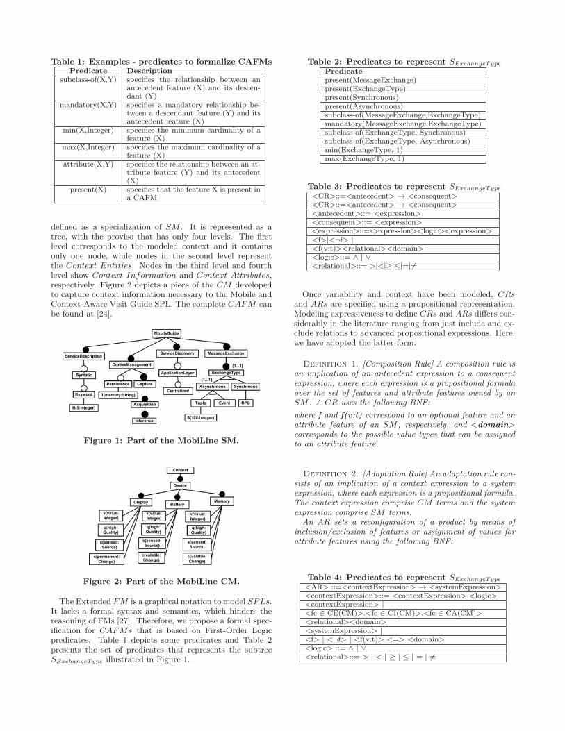
Table 1: Examples - predicates to formalize CAFMsPredicate Description
subclass-of(X,Y) specifies the relationship between anantecedent feature (X) and its descen-dant (Y)
mandatory(X,Y) specifies a mandatory relationship be-tween a descendant feature (Y) and itsantecedent feature (X)
min(X,Integer) specifies the minimum cardinality of afeature (X)
max(X,Integer) specifies the maximum cardinality of afeature (X)
attribute(X,Y) specifies the relationship between an at-tribute feature (Y) and its antecedent(X)
present(X) specifies that the feature X is present ina CAFM
defined as a specialization of SM . It is represented as atree, with the proviso that has only four levels. The firstlevel corresponds to the modeled context and it containsonly one node, while nodes in the second level representthe Context Entities. Nodes in the third level and fourthlevel show Context Information and Context Attributes,respectively. Figure 2 depicts a piece of the CM developedto capture context information necessary to the Mobile andContext-Aware Visit Guide SPL. The complete CAFM canbe found at [24].
Figure 1: Part of the MobiLine SM.
Figure 2: Part of the MobiLine CM.
The Extended FM is a graphical notation to model SPLs.It lacks a formal syntax and semantics, which hinders thereasoning of FMs [27]. Therefore, we propose a formal spec-ification for CAFMs that is based on First-Order Logicpredicates. Table 1 depicts some predicates and Table 2presents the set of predicates that represents the subtreeSExchangeType illustrated in Figure 1.
Table 2: Predicates to represent SExchangeType
Predicatepresent(MessageExchange)present(ExchangeType)present(Synchronous)present(Asynchronous)subclass-of(MessageExchange,ExchangeType)mandatory(MessageExchange,ExchangeType)subclass-of(ExchangeType, Synchronous)subclass-of(ExchangeType, Asynchronous)min(ExchangeType, 1)max(ExchangeType, 1)
Table 3: Predicates to represent SExchangeType
<CR>::=<antecedent> → <consequent><CR>::=<antecedent> → <consequent><antecedent>::= <expression><consequent>::= <expression><expression>::=<expression><logic><expression>|<f>|<¬f> |<f(v:t)><relational><domain><logic>::= ∧ | ∨<relational>::= >|<|≥|≤|=|�=
Once variability and context have been modeled, CRsand ARs are specified using a propositional representation.Modeling expressiveness to define CRs and ARs differs con-siderably in the literature ranging from just include and ex-clude relations to advanced propositional expressions. Here,we have adopted the latter form.
Definition 1. [Composition Rule] A composition rule isan implication of an antecedent expression to a consequentexpression, where each expression is a propositional formulaover the set of features and attribute features owned by anSM . A CR uses the following BNF:
where f and f(v:t) correspond to an optional feature and anattribute feature of an SM , respectively, and <domain>corresponds to the possible value types that can be assignedto an attribute feature.
Definition 2. [Adaptation Rule] An adaptation rule con-sists of an implication of a context expression to a systemexpression, where each expression is a propositional formula.The context expression comprise CM terms and the systemexpression comprise SM terms.
An AR sets a reconfiguration of a product by means ofinclusion/exclusion of features or assignment of values forattribute features using the following BNF:
Table 4: Predicates to represent SExchangeType
<AR> ::=<contextExpression> → <systemExpression><contextExpression>::= <contextExpression> <logic><contextExpression> |<fc ∈ CE(CM)>.<fc ∈ CI(CM)>.<fc ∈ CA(CM)><relational><domain><systemExpression> |<f> | <¬f> | <f(v:t)> <=> <domain><logic> ::= ∧ | ∨<relational>::= > | < | ≥ | ≤ | = | �=
56
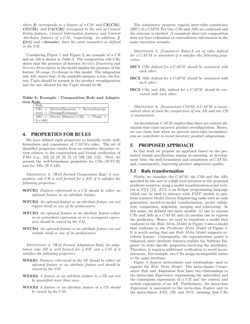
where fc corresponds to a feature of a CM and CE(CM),CI(CM), and CA(CM) correspond to the sets of ContextEntity features, Context Information features, and ContextAttributes features of a CM , respectively. In addition, f,f(v:t) and <domain> have the same semantics as definedin the CR.
Considering Figure 1 and Figure 2, an example of a CRand an AR is shown in Table 3. The composition rule CR1
states that the presence of features Service Discovery andService Description in the model implies the presence of thefeature Message Exchange in this model. The adaptationrule AR1 states that, if the available memory is low, the fea-ture Tuple should be present in the product reconfigurationand the size allowed for the Tuple should be 80.
Table 5: Example - Composition Rule and Adapta-tion Rule
RuleCR1 = (ServiceDiscovery ∧ ServiceDescrip-tion) → (MessageExchange)AR1 = (Device.Memory.v<50) → (Tuple ∧S.v=80)
4. PROPERTIES FOR RULESWe have defined eight properties to formally verify well-
formedness and consistency of CAFMs rules. The set ofidentified properties results from an extensive literature re-view relative to the construction and formal verification ofFMs (e.g., [22] [4] [8] [9] [5] [1] [29] [10] [13]). Next, wepresent the well-formedness properties for CRs (WFCR)and for ARs (WFAR).
Definition 3. [Well Formed Composition Rule] A com-position rule CR is well formed for a SM if it satisfies thefollowing properties.
WFCR1 Features referenced in a CR should be either anoptional feature or an attribute feature.
WFCR2 An optional feature or an attribute feature can notrequire itself or one of its predecessors.
WFCR3 An optional feature or an attribute feature eitherin an antecedent expression or in a consequent expres-sion should be owned by the SM .
WFCR4 An optional feature or an attribute feature can notexclude itself or one of its predecessors.
Definition 4. [Well Formed Adaptation Rule] An adap-tation rule AR is well formed for a SM and a CM if itsatisfies the following properties.
WFAR1 Features referenced in the SE should be either anoptional feature or an attribute feature and should beowned by the SM .
WFAR2 A feature or an attribute feature in a SE can notbe quantified more than once.
WFAR3 A feature or an attribute feature in a CE shouldbe owned by the CM .
The consistency property regards inter-rules consistency(IRC) of a CAFM. For this, CRs and ARs are combined andthe outcome is checked. A consistent inter-rule compositiondoes not have redundant or contradictory information in thesame execution scenario.
Definition 5. [Consistent Rules]A set of rules definedfor a CAFM is consistent if it satisfies the following prop-erties.
IRC1 CRs defined for a CAFM should be consistent witheach other.
IRC2 ARs defined for a CAFM should be consistent witheach other.
IRC3 CRs and ARs defined for a CAFM should be con-sistent with each other.
Definition 6. [Inconsistent CAFM] A CAFM is incon-sistent when at least the conjunction of one AR and one CRis inconsistent.
An inconsistent CAFM implies that there are context sit-uations that cause incorrect product reconfiguration. Hence,we can claim that when we prevent inter-rules inconsisten-cies we contribute to avoid incorrect product adaptations.
5. PROPOSED APPROACHIn this work we propose an approach based on the pre-
sented formal specification aiming at ensuring, at develop-ment time, the well-formedness and consistency of CAFMsand, consequently, improving product adaptation quality.
5.1 Rule transformationFirstly, we translate the CAFM , the CRs and the ARs
specified by the user in a high level notation to the proposedpredicate notation, using a model transformation script writ-ten in ETL [14]. ETL is an Eclipse programming languagewhich can be used to interact with EMF models to per-form common Model Driven Engineering tasks such as codegeneration, model-to-model transformation, model valida-tion, comparison, migration, merging and refactoring. Inthis sense, we defined two meta models: (i) one to expressCRs and ARs in a CAFM ; and (ii) another one to expressthe predicates. Hence, we need to transform a model thatconforms to the Rule Meta Model in Figure 3 into a modelthat conforms to the Predicate Meta Model of Figure 4.It is worth noting that our Rule Meta Model supports at-tribute feature. Consequently, the expressiveness power isenhanced, since attribute features enables the Software En-gineer to write specific properties involving the attributes.Therefore, it requires additional verification to avoid incon-sistencies. For example, two CRs assign incompatible valuesto the same attribute.
Figure 3 depicts meta-classes and relationships used tocapture the Rule Meta Model. The meta-classes Compo-sition Rule and Adaptation Rule have two relationships tothe meta-class Expression, representing the antecedent andthe consequent expressions of a CR and the context andsystem expressions of an AR. Furthermore, the meta-classExpression is associated to the meta-class Feature and tothe meta-classes AND, OR, and NOT, meaning that CRs
57
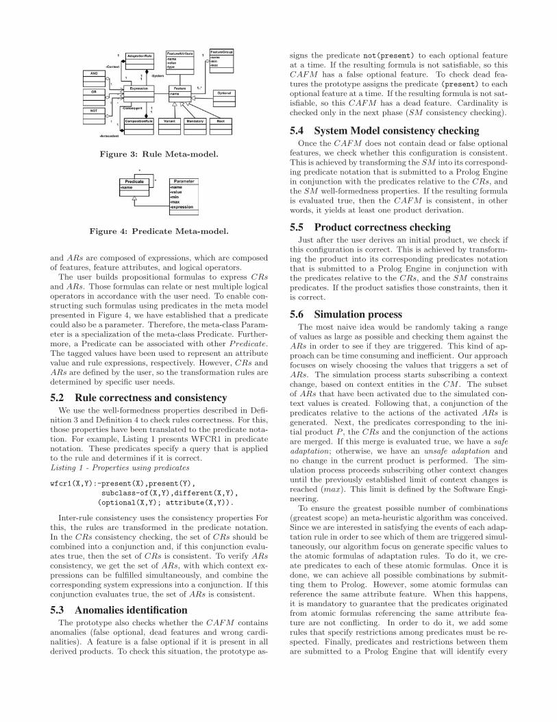
Figure 3: Rule Meta-model.
Figure 4: Predicate Meta-model.
and ARs are composed of expressions, which are composedof features, feature attributes, and logical operators.
The user builds propositional formulas to express CRsand ARs. Those formulas can relate or nest multiple logicaloperators in accordance with the user need. To enable con-structing such formulas using predicates in the meta modelpresented in Figure 4, we have established that a predicatecould also be a parameter. Therefore, the meta-class Param-eter is a specialization of the meta-class Predicate. Further-more, a Predicate can be associated with other Predicate.The tagged values have been used to represent an attributevalue and rule expressions, respectively. However, CRs andARs are defined by the user, so the transformation rules aredetermined by specific user needs.
5.2 Rule correctness and consistencyWe use the well-formedness properties described in Defi-
nition 3 and Definition 4 to check rules correctness. For this,those properties have been translated to the predicate nota-tion. For example, Listing 1 presents WFCR1 in predicatenotation. These predicates specify a query that is appliedto the rule and determines if it is correct.Listing 1 - Properties using predicates
wfcr1(X,Y):-present(X),present(Y),
subclass-of(X,Y),different(X,Y),
(optional(X,Y); attribute(X,Y)).
Inter-rule consistency uses the consistency properties Forthis, the rules are transformed in the predicate notation.In the CRs consistency checking, the set of CRs should becombined into a conjunction and, if this conjunction evalu-ates true, then the set of CRs is consistent. To verify ARsconsistency, we get the set of ARs, with which context ex-pressions can be fulfilled simultaneously, and combine thecorresponding system expressions into a conjunction. If thisconjunction evaluates true, the set of ARs is consistent.
5.3 Anomalies identificationThe prototype also checks whether the CAFM contains
anomalies (false optional, dead features and wrong cardi-nalities). A feature is a false optional if it is present in allderived products. To check this situation, the prototype as-
signs the predicate not(present) to each optional featureat a time. If the resulting formula is not satisfiable, so thisCAFM has a false optional feature. To check dead fea-tures the prototype assigns the predicate (present) to eachoptional feature at a time. If the resulting formula is not sat-isfiable, so this CAFM has a dead feature. Cardinality ischecked only in the next phase (SM consistency checking).
5.4 System Model consistency checkingOnce the CAFM does not contain dead or false optional
features, we check whether this configuration is consistent.This is achieved by transforming the SM into its correspond-ing predicate notation that is submitted to a Prolog Enginein conjunction with the predicates relative to the CRs, andthe SM well-formedness properties. If the resulting formulais evaluated true, then the CAFM is consistent, in otherwords, it yields at least one product derivation.
5.5 Product correctness checkingJust after the user derives an initial product, we check if
this configuration is correct. This is achieved by transform-ing the product into its corresponding predicates notationthat is submitted to a Prolog Engine in conjunction withthe predicates relative to the CRs, and the SM constrainspredicates. If the product satisfies those constraints, then itis correct.
5.6 Simulation processThe most naive idea would be randomly taking a range
of values as large as possible and checking them against theARs in order to see if they are triggered. This kind of ap-proach can be time consuming and inefficient. Our approachfocuses on wisely choosing the values that triggers a set ofARs. The simulation process starts subscribing a contextchange, based on context entities in the CM . The subsetof ARs that have been activated due to the simulated con-text values is created. Following that, a conjunction of thepredicates relative to the actions of the activated ARs isgenerated. Next, the predicates corresponding to the ini-tial product P , the CRs and the conjunction of the actionsare merged. If this merge is evaluated true, we have a safeadaptation; otherwise, we have an unsafe adaptation andno change in the current product is performed. The sim-ulation process proceeds subscribing other context changesuntil the previously established limit of context changes isreached (max). This limit is defined by the Software Engi-neering.
To ensure the greatest possible number of combinations(greatest scope) an meta-heuristic algorithm was conceived.Since we are interested in satisfying the events of each adap-tation rule in order to see which of them are triggered simul-taneously, our algorithm focus on generate specific values tothe atomic formulas of adaptation rules. To do it, we cre-ate predicates to each of these atomic formulas. Once it isdone, we can achieve all possible combinations by submit-ting them to Prolog. However, some atomic formulas canreference the same attribute feature. When this happens,it is mandatory to guarantee that the predicates originatedfrom atomic formulas referencing the same attribute fea-ture are not conflicting. In order to do it, we add somerules that specify restrictions among predicates must be re-spected. Finally, predicates and restrictions between themare submitted to a Prolog Engine that will identify every
58
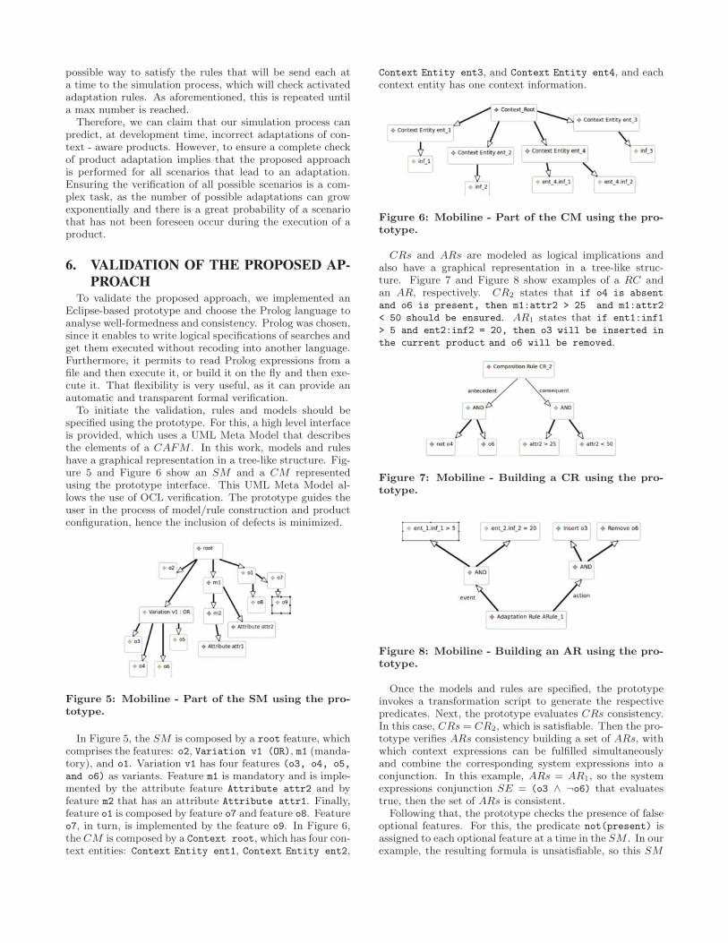
possible way to satisfy the rules that will be send each ata time to the simulation process, which will check activatedadaptation rules. As aforementioned, this is repeated untila max number is reached.
Therefore, we can claim that our simulation process canpredict, at development time, incorrect adaptations of con-text - aware products. However, to ensure a complete checkof product adaptation implies that the proposed approachis performed for all scenarios that lead to an adaptation.Ensuring the verification of all possible scenarios is a com-plex task, as the number of possible adaptations can growexponentially and there is a great probability of a scenariothat has not been foreseen occur during the execution of aproduct.
6. VALIDATION OF THE PROPOSED AP-PROACH
To validate the proposed approach, we implemented anEclipse-based prototype and choose the Prolog language toanalyse well-formedness and consistency. Prolog was chosen,since it enables to write logical specifications of searches andget them executed without recoding into another language.Furthermore, it permits to read Prolog expressions from afile and then execute it, or build it on the fly and then exe-cute it. That flexibility is very useful, as it can provide anautomatic and transparent formal verification.
To initiate the validation, rules and models should bespecified using the prototype. For this, a high level interfaceis provided, which uses a UML Meta Model that describesthe elements of a CAFM . In this work, models and ruleshave a graphical representation in a tree-like structure. Fig-ure 5 and Figure 6 show an SM and a CM representedusing the prototype interface. This UML Meta Model al-lows the use of OCL verification. The prototype guides theuser in the process of model/rule construction and productconfiguration, hence the inclusion of defects is minimized.
Figure 5: Mobiline - Part of the SM using the pro-totype.
In Figure 5, the SM is composed by a root feature, whichcomprises the features: o2, Variation v1 (OR), m1 (manda-tory), and o1. Variation v1 has four features (o3, o4, o5,
and o6) as variants. Feature m1 is mandatory and is imple-mented by the attribute feature Attribute attr2 and byfeature m2 that has an attribute Attribute attr1. Finally,feature o1 is composed by feature o7 and feature o8. Featureo7, in turn, is implemented by the feature o9. In Figure 6,the CM is composed by a Context root, which has four con-text entities: Context Entity ent1, Context Entity ent2,
Context Entity ent3, and Context Entity ent4, and eachcontext entity has one context information.
Figure 6: Mobiline - Part of the CM using the pro-totype.
CRs and ARs are modeled as logical implications andalso have a graphical representation in a tree-like struc-ture. Figure 7 and Figure 8 show examples of a RC andan AR, respectively. CR2 states that if o4 is absent
and o6 is present, then m1:attr2 > 25 and m1:attr2
< 50 should be ensured. AR1 states that if ent1:inf1
> 5 and ent2:inf2 = 20, then o3 will be inserted in
the current product and o6 will be removed.
Figure 7: Mobiline - Building a CR using the pro-totype.
Figure 8: Mobiline - Building an AR using the pro-totype.
Once the models and rules are specified, the prototypeinvokes a transformation script to generate the respectivepredicates. Next, the prototype evaluates CRs consistency.In this case, CRs = CR2, which is satisfiable. Then the pro-totype verifies ARs consistency building a set of ARs, withwhich context expressions can be fulfilled simultaneouslyand combine the corresponding system expressions into aconjunction. In this example, ARs = AR1, so the systemexpressions conjunction SE = (o3 ∧ ¬o6) that evaluatestrue, then the set of ARs is consistent.
Following that, the prototype checks the presence of falseoptional features. For this, the predicate not(present) isassigned to each optional feature at a time in the SM . In ourexample, the resulting formula is unsatisfiable, so this SM
59
has one false optional feature. On the other hand, assigningthe predicate (present) to each optional feature at a timeand the SM is satisfiable, then this SM does not have deadfeatures.
To check if the SM is consistent, the prototype evaluatesthe conjunction of the predicates corresponding to the SMwith the predicates relative to the CRs, and predicates ofthe well formedness-rules. In this case, the SM is consistent.
Next, the user configures a product and the prototypechecks whether this product is correct. For this, the pro-totype transforms the product configuration into predicatesthat are submitted to the Prolog Engine in conjunction withthe predicates relative to the CRs and the SM constraints.If the resulting formula is evaluated true, then the currentproduct is correct.
Finally, the prototype uses the simulation process, whichsubscribes event changes to context and gets the ARs thathave been activated. Next, it evaluates if the AR1 violatesthe CR2, implying that the SM derives an unsafe adapta-tion. First, it verifies if any inconsistency between the formu-las that comprise the context expressions CE exists. In thiscase, CE evaluates to true. Next, the prototype creates theconjunction of the system expressions SE relative to the CE.In this example, it verifies (SE and CR2) and finds the fol-lowing inconsistency (not(present(o6)),present(o6). So,AR1 violates the CR2 and the CAFM can generate unsafeadaptations.
In summary, if the actions relative to ARs break one ormore CR, the CAFM has inconsistencies and derives un-safe adaptations regardless the product configuration. How-ever, there are situations in which the actions break oneor more CRs just in a specific adaptation. To detect thisproblem, the simulation process is essential. For example, letCR′ = if (Storage is present and Wifi is absent) then
Record Movies is enabled and SE = Include Storage.To determine if this SE breaks CR′ it is necessary to checkthe actions against the current product configuration, sincethe feature Include Storage is not present in CR′. For in-stance, if the current product configuration does not containthe feature Record Movies, then the configuration breaksthe CR′, otherwise, the actions in the subset, when appliedover the configuration, do not generate an unsafe adapta-tion. Accordingly, we can state that well-formedness andconsistency properties are necessary to identify unsafe adap-tations, but they are not sufficient.
7. CONCLUSIONS AND FUTURE WORKIn this work, we have proposed an approach that aims at
preventing, at development time, defects of product adapta-tion in CASPLs. This approach comprises well-formednessand consistency verification of rules specified in CAFMs, andpreventing defects in product adaptation. We used a formalspecification to capture the models and rules used to buildCAFMs. This specification was enriched with propertiesthat define how to build well-formed and consistent CAFMsrules. This approach is validated by a prototype that au-tomates the proposed verification process. The prototypeuses model transformations to automatically generate therespective predicates to CAFM, the composition rules andadaptation rules and invokes a theorem prover to formallyverify the proposed properties against those elements. So,the formal verification is performed in a transparent way tothe end user. The scalability is directly related to the solver
used. In our case, to run queries in Prolog, the selected toollimits the scalability of the proposed approach.
The simulation process proposed succeeded to detect andprevent defects in products adapted due to changes in thecontext. The fact that this simulation process ensure thecorrectness of a variety of situations that can lead to recon-figurations of products can also be considered an importantoutcome of this research. In order to use the proposed simu-lation process at run time, it would be necessary to use someframework, for instance the WildCat Toolkit [12], that au-tomatically detects the presence of new context entities. Inaddition, the user must set the new scenarios that have bemonitored at every new entity identified.
As future work, we intend to apply our approach in otherCASPLs, such as HSR Product Line [19], in order to ana-lyze better its benefits. Unfortunately, we did not find manyCASPLs in the literature. Hence, we intend to perform anexperiment using randomly generated CAFMs. Addition-ally, self-adaptation, maintenance, and evolution of SPL aretopics of increasing interest to the SPL community. Webelieve the combination of the proposed approach and self-adaptive approaches could bear a significant step to pre-dict the quality of product adaptation, since no significantchange is necessary. For this, it is necessary to use somemechanism that some mechanism that has the ability torecognize new context entities and insert them in the adap-tation rules. User participation is necessary to define newadaptation rules based on the new context entities identified.Thus, our work can potentially contribute to the ongoing re-search on those topics.
8. ACKNOWLEDGMENTSThis work is a partial result of the UbiStructure project
supported by CNPq (MCT/CNPq 14/2011 - Universal) un-der grant number 481417/2011-7. Thanks also to CNPq forthe scholarships of Rossana M.C. Andrade under grant num-ber 314021/2009-4, Fabiana G. Marinho under grant num-ber 552924/2008.3, and Claudia Werner under grant number304097/2010-1.
9. REFERENCES[1] Automated error analysis for the agilization of feature
modeling. Journal of Systems and Software,81(6):883–896, Jun 2008.
[2] M. Acher, P. Collet, P. Lahire, and R. B. France.Comparing approaches to implement feature modelcomposition. In ECMFA, pages 3–19, 2010.
[3] M. Acher, P. Collet, P. Lahire, and R. B. France.Slicing feature models. In ASE, pages 424–427, 2011.
[4] D. Batory. Feature models, grammars, andpropositional formulas. In H. Obbink and K. Pohl,editors, Software Product Lines, volume 3714 ofLecture Notes in Computer Science, pages 7–20.Springer Berlin / Heidelberg, 2005.10.1007/11554844 3.
[5] D. Benavides. On the Automated Analysis of SoftwareProduct Lines Using Feature Models. A framework fordeveloping automated tool support. PhD thesis,University of Seville, 2007.
[6] D. Benavides, S. Segura, and A. Ruiz-Cortes.Automated analysis of feature models 20 years later:
60
A literature review. Information Systems,35(6):615–636, 2010.
[7] K. Czarnecki, S. Helsen, and U. Eisenecker.Formalizing cardinality-based feature models and theirspecialization. In Software Process: Improvement andPractice, page 2005, 2005.
[8] K. Czarnecki, S. Helsen, and U. W. Eisenecker. Stagedconfiguration using feature models. In SPLC, pages266–283, 2004.
[9] K. Czarnecki, C. H. P. Kim, and K. T. Kalleberg.Feature models are views on ontologies. In SPLC,pages 41–51. IEEE Computer Society, 2006.
[10] K. Czarnecki and K. Pietroszek. Verifyingfeature-based model templates against well-formednessocl constraints. In Proceedings of the 5th internationalconference on Generative programming and componentengineering, GPCE ’06, pages 211–220, New York,NY, USA, 2006. ACM.
[11] K. Czarnecki and A. Wasowski. Feature diagrams andlogics: There and back again. In Proceedings of the11th International Software Product Line Conference,pages 23–34, Washington, DC, USA, 2007. IEEEComputer Society.
[12] P.-C. David and T. Ledoux. Wildcat: a genericframework for context-aware applications. InProceedings of the 3rd international workshop onMiddleware for pervasive and ad-hoc computing,MPAC ’05, pages 1–7, New York, NY, USA, 2005.ACM.
[13] A. O. Elfaki, S. Phon-Amnuaisuk, and C. K. Ho.Knowledge based method to validate feature models.In S. Thiel and K. Pohl, editors, SPLC (2), pages217–225. Lero Int. Science Centre, University ofLimerick, Ireland, 2008.
[14] Etl - epsilon transformation language, March 2012.http://www.eclipse.org/epsilon/doc/etl/.
[15] P. Fernandes, C. Werner, and L. G. P. Murta. Featuremodeling for context-aware software product lines. InSEKE, pages 758–763. Knowledge Systems InstituteGraduate School, 2008.
[16] R. Gheyi, T. Massoni, and P. Borba. A theory forfeature models in alloy. In Proceedings of the ACMSIGSOFY First Alloy Workshop, page 71–80,Portland, United States, nov 2006.
[17] S. Hallsteinsen, M. Hinchey, S. Park, and K. Schmid.Dynamic software product lines. Computer, 41:93–95,2008.
[18] K. C. Kang, S. G. Cohen, J. A. Hess, W. E. Novak,and A. S. Peterson. Feature-oriented domain analysis(foda) feasibility study. Technical report,Carnegie-Mellon University Software EngineeringInstitute, November 1990.
[19] J. Lee and K. Kang. A feature-oriented approach todeveloping dynamically reconfigurable products inproduct line engineering. In Software Product LineConference, 2006 10th International, pages 10pp.–140, 0-0 2006.
[20] R. E. Lopez-Herrejon and A. Egyed. C2mv2:Consistency and composition for managing variabilityin multi-view systems. In CSMR, pages 347–350, 2011.
[21] M. E. Maia, L. S. Rocha, and R. M. Andrade.Requirements and challenges for building
service-oriented pervasive middleware. In Proceedingsof the 2009 international conference on Pervasiveservices, ICPS ’09, pages 93–102, New York, NY,USA, 2009. ACM.
[22] M. Mannion. Using first-order logic for product linemodel validation. In Proceedings of the SecondInternational Conference on Software Product Lines,SPLC 2, pages 176–187, London, UK, UK, 2002.Springer-Verlag.
[23] F. Marinho, F. Lima, J. Ferreira Filho, L. Rocha,M. Maia, S. de Aguiar, V. Dantas, W. Viana,R. Andrade, E. Teixeira, and C. Werner. A softwareproduct line for the mobile and context-awareapplications domain. In J. Bosch and J. Lee, editors,Software Product Lines: Going Beyond, volume 6287of Lecture Notes in Computer Science, pages 346–360.Springer Berlin / Heidelberg, 2010.10.1007/978-3-642-15579-6 24.
[24] Mobiline - a software product line for the developmentof mobile and context-aware applications, March 2010.http://mobiline.great.ufc.br/index.php.
[25] J. Sun, H. Zhang, Y.-F. Li, and H. H. Wang. Formalsemantics and verification for feature modeling. InICECCS, pages 303–312, 2005.
[26] N. Ubayashi, S. Nakajima, and M. Hirayama.Context-dependent product line practice forconstructing reliable embedded systems. In J. Boschand J. Lee, editors, Software Product Lines: GoingBeyond, volume 6287 of Lecture Notes in ComputerScience, pages 1–15. Springer Berlin / Heidelberg,2010. 10.1007/978-3-642-15579-6 1.
[27] H. H. Wang, Y. F. Li, J. Sun, H. Zhang, and J. Pan.Verifying feature models using owl. Web Semant.,5:117–129, June 2007.
[28] L. A. Zaid, F. Kleinermann, and O. De Troyer.Applying semantic web technology to featuremodeling. In Proceedings of the 2009 ACM symposiumon Applied Computing, SAC ’09, pages 1252–1256,New York, NY, USA, 2009. ACM.
[29] W. Zhang, H. Zhao, and H. Mei. A propositionallogic-based method for verification of feature models.In ICFEM, pages 115–130, 2004.
61
Towards a Catalog of Variability Evolution Patterns: TheLinux Kernel Case
Leonardo PassosUniversity of Waterloo
Krzysztof CzarneckiUniversity of Waterloo
Andrzej WasowskiIT University of Copenhagen
ABSTRACTA complete understanding of evolution of variability requiresanalysis over all project spaces that contain it: source code,build system and the variability model. Aiming at betterunderstanding of how complex variant-rich software evolve,we set to study one, the Linux kernel, in detail. We qual-itatively analyze a number of evolution steps in the kernelhistory and present our findings as a preliminary sample ofa catalog of evolution patterns. Our patterns focus on howthe variability evolves when features are removed from thevariability model, but are kept as part of the software. Theidentified patterns relate changes to the variability model,the build system, and implementation code. Despite prelim-inary, they already indicate evolution steps that have notbeen captured by prior studies, both empirical and theoret-ical.
Categories and Subject DescriptorsD.2.7 [Distribution, Maintenance, and Enhancement]:Restructuring, reverse engineering, and reengineering
General TermsDesign
Keywordsvariability, patterns, evolution, software product lines, Linux
1. INTRODUCTIONVariability evolution is a core point in evolving software
product lines [6]. Changes in the variability dictate whichfeatures are obsolete, which are new, which products are stillpossible to be generated, which dependencies still hold, etc.Despite its importance, the Software Product Line commu-nity has little knowledge on how variability evolution occursin practice and which changes are performed when realizingthem. The few existing studies do not take feature removal
Permission to make digital or hard copies of all or part of this work forpersonal or classroom use is granted without fee provided that copies arenot made or distributed for profit or commercial advantage and that copiesbear this notice and the full citation on the first page. To copy otherwise, torepublish, to post on servers or to redistribute to lists, requires prior specificpermission and/or a fee.FOSD’12, September 24–25, 2012, Dresden, Germany.Copyright 2012 ACM 978-1-4503-1309-4/12/09 ...$15.00.
into account [4, 5, 12], while others [14, 8] focus on thevariability model alone. Altogether, they fail to cover thevariability evolution when features are removed from thevariability model, while still being kept part of the software.To address this issue, we study a real world variant richsoftware –the Linux kernel– and extract evolution patternsdescribing how variability evolves across different artifacts(variability model, build files, and source code) when fea-tures are erased from the variability model, but not fromthe software itself.
The Linux kernel is the most successful open source soft-ware, containing a rich and extensive variability that allowsit to support a large range of architectures, device driversand application domains [15].
Variability in the Linux kernel is vertically present in threeseparate, but related spaces [10]: configuration space: kernelconfiguration files (Kconfig), comprising the Linux variabil-ity model; compilation space: kernel build files (KBuild),mostly written as Makefiles with implicit rules [16]; imple-mentation space: realization of all features, mostly writtenas C code.
The Linux kernel configuration space was first studied byShe et al. [14], who analyze and compare its complexitywith regards to existing models in SPLOT [9]. Lotufo etal. [8] extend that work by a longitudinal analysis over thex86 architecture. Among other things, the authors inspectthe Linux variability model growth pace, how its structureis affected and which changes developers execute over time.
A sole focus on the configuration space, however, does notprovide a full understanding of how variability evolves. Infact, such an analysis can easily lead to wrong conclusions.The variability model of the x86 64 architecture illustratesthat: between releases 2.6.32 and 2.6.33, 281 new featurenames were added, while 43 were removed. A closer inspec-tion of all spaces of the commits removing such features ledus to conclude that 35% of them continued to exist; as ourpatterns show, developers remove these features from thevariability model while migrating them to the implementa-tion side or merging them with other features.1
The patterns we present is the first work capturing vari-ability evolution in a multi-space setting of a complex real-world variant rich software. Furthermore, our patterns com-prise evolution steps not covered by previous work [4, 5, 12,14, 8].
We believe that a holistic understanding of evolution prac-tice of complex systems with rich variability will have sig-nificant impact on product line research, including work
1Renames were also noted.
62
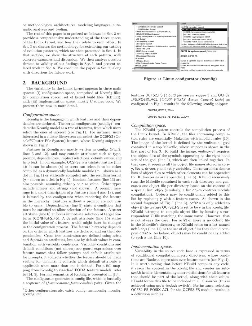
on methodologies, architectures, modeling languages, auto-matic analyses and tooling.
The rest of this paper is organized as follows: in Sec. 2 weprovide a comprehensive understanding of the three spacesof the Linux kernel, and how they relate to each other. InSec. 3 we discuss the methodology for extracting our catalogof evolution patterns, which are then presented in Sec. 4. Inthat section, we show the structure of each pattern, withconcrete examples and discussion. We then analyze possiblethreats to validity of our findings in Sec. 5, and present re-lated work in Sec. 6. We conclude the paper in Sec. 7, alongwith directions for future work.
2. BACKGROUNDThe variability in the Linux kernel appears in three main
spaces: (i) configuration space, comprised of Kconfig files;(ii) compilation space: set of kernel build files (KBuild),and; (iii) implementation space: mostly C source code. Wepresent them now in more detail.
Configuration space.Kconfig is the language in which features and their depen-
dencies are declared. The kernel configurator (xconfig)2 ren-ders the Kconfig model as a tree of features, from which usersselect the ones of interest (see Fig. 1). For instance, usersinterested in a cluster file system can select the OCSFS2 (Or-acle™Cluster File System) feature, whose Kconfig snippet isshown in Fig. 2.
Features in Kconfig are mostly written as configs (Fig. 2,lines 3 and 12), and may contain attributes such as type,prompt, dependencies, implied selections, default values, andhelp text. In our example, OCSFS2 is a tristate feature (line4): it can be absent (n) or users can select it to be eithercompiled as a dynamically loadable module (m – shown as adot in Fig. 1) or statically compiled into the resulting kernel(y – shown as a tick in Fig. 1). Boolean features (line 13) arealso possible, assuming either y or n as value. Other typesinclude integer and strings (not shown). A prompt mes-sage is a short description of a feature (lines 4 and 13), andit is used by the configurator when rendering the featurein the hierarchy. Features without a prompt are not visi-ble to users. Dependencies (line 5) state a condition thatmust be satisfied to allow selection of the feature. A selectattribute (line 6) enforces immediate selection of target fea-tures (CONFIGFS FS). A default attribute (line 15) statesthe initial value of a feature, which might later be changedin the configuration process. The feature hierarchy dependson the order in which features are declared and on their de-pendencies. Cross tree constraints are defined using selectand depends on attributes, but also by default values in com-bination with visibility conditions. Visibility conditions anddefault conditions (not shown) are guard expressions overfeature names that follow prompt and default attributes:for prompts, it controls whether the feature should be madevisible; for defaults, it controls which default attribute isapplicable when more than one is defined. For a full map-ping from Kconfig to standard FODA feature models, referto [14, 3]. Formal semantics of Kconfig is presented in [13].
The configurator generates a .config file, which is basicallya sequence of (feature-name, feature-value) pairs. Given the
2Other configurators also exist: config, menuconfig, nconfig,gconfig, etc.
Figure 1: Linux configurator (xconfig)
features OCFS2 FS (OCFS file system support) and OCFS2FS POSIX ACL (OCFS POSIX Access Control Lists) asconfigured in Fig. 1 results in the following .config snippet:
CONFIG_OCFS2_FS=m...CONFIG_OCFS2_FS_POSIX_ACL=y
Compilation space.The KBuild system controls the compilation process of
the Linux kernel. In KBuild, the files containing compila-tion rules are essentially Makefiles with implicit rules [16].The image of the kernel is defined by the vmlinux-all goalcontained in a top Makefile, whose snippet is shown in thefirst part of Fig. 3. To build the image, vmlinux-all requiresthe object files of the symbols appearing at the right handside of the goal (line 3), which are then linked together. Inthat case, it requires all the object file names stored in core-y, libs-y, drivers-y and net-y variables. These variables denotelists of object files to which other elements can be appendedto. If directories are appended (line 5), KBuild recursivelyruns the Makefile contained in each such directory and gen-erates one object file per directory based on the content ofa special list: obj-y (similarly, a list obj-m controls modulecompilation). Objects may be conditionally added to thislist by replacing y with a feature name. As shown in thesecond fragment of Fig. 3 (line 3), ocfs2.o is only added toobj-y if the feature OCFS2 FS is set to be y in the .config file.KBuild attempts to compile object files by locating a cor-respondent C file matching the same name. However, thatis not always the case. For ocfs2.o, there is no ocfs2.c filein the Makefile’s directory, so KBuild relies on a list namedocfs2-objs (line 11) as the set of object files that should com-pose ocfs2.o. As before, objects may be conditionally addedto such a list (line 10).
Implementation space.Variability in the source code base is expressed in terms
of conditional compilation macro directives, whose condi-tions are Boolean expression over feature names (see Fig. 4).It is worth noting that before KBuild compiles any code,it reads the content in the .config file and creates an auto-conf.h header file containing macro definitions for all featuresthat should be part of the kernel, along with their values.KBuild forces this file to be included in all C sources (this isachieved using gcc’s -include switch). For instance, selectingOCFS2 FS POSIX ACL for the OCFS2 FS module results ina definition such as
63
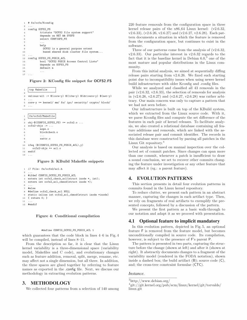
1 # fs/ocfs/Kconfig2 ...3 config OCFS2_FS4 tristate "OCFS2 file system support"5 depends on NET && SYSFS6 select CONFIGFS_FS7 ...8 help9 OCFS2 is a general purpose extent
10 based shared disk cluster file system...11 ...12 config OCFS2_FS_POSIX_ACL13 bool "OCFS2 POSIX Access Control Lists"14 depends on OCFS2_FS15 default n16 ...17 ...
Figure 2: KConfig file snippet for OCFS2 FS
1 top Makefile2
3 vmlinux-all := $(core-y) $(libs-y) $(drivers-y) $(net-y)4 ...5 core-y += kernel/ mm/ fs/ ipc/ security/ crypto/ block/6 ...
1 fs/ocfs2/Makefile2
3 obj-$(CONFIG_OCFS2_FS) += ocfs2.o ...4 ocfs2-objs := ...5 aops.o6 blockcheck.o7 ...8 xattr.o9
10 ifeq ($(CONFIG_OCFS2_FS_POSIX_ACL),y)11 ocfs2-objs += acl.o12 endif13 ...
Figure 3: KBuild Makefile snippets
1 // File: fs/ocfs2/acl.h2 ...3 #ifdef CONFIG_OCFS2_FS_POSIX_ACL4 extern int ocfs2_check_acl(struct inode *, int);5 extern int ocfs2_acl_chmod(struct inode *);6 ...7 #else8 #define ocfs2_check_acl NULL9 static inline int ocfs2_acl_chmod(struct inode *inode)
10 { return 0; }11 ...12 #endif
Figure 4: Conditional compilation
#define CONFIG_OCFS2_FS_POSIX_ACL 1
which guarantees that the code block in lines 4–6 in Fig. 4will be compiled, instead of lines 8–11.
From the description so far, it is clear that the Linuxkernel variability is a three-dimensional space (variabilitymodel, Makefiles and C code), and evolutionary changessuch as feature addition, removal, split, merge, rename, etc.may affect not a single dimension, but all three. In addition,the three spaces are glued together by referring to featurenames as exported in the .config file. Next, we discuss ourmethodology in extracting evolution patterns.
3. METHODOLOGYWe collected four patterns from a selection of 140 among
220 feature removals from the configuration space in threekernel release pairs of the x86 64 Linux kernel: (v2.6.32,v2.6.33), (v2.6.26, v2.6.27) and (v2.6.27, v2.6.28). Each pat-tern documents a situation in which the feature is removedfrom the configuration space, but continues to exist in thesoftware.
Three of our patterns come from the analysis of (v2.6.32,v2.6.33). Our particular interest in v2.6.32 regards to thefact that it is the baseline kernel in Debian 6.0,3 one of themost mature and popular distributions in the Linux com-munity.
From this initial analysis, we aimed at sequentially diffingrelease pairs starting from v2.6.26. We fixed such startingpoint due to incompatibility issues when using newer kernelbuild infrastructure with older Kconfig and .config files.
While we analyzed and classified all 43 removals in thepair (v2.6.32, v2.6.33), the selection of removals for analysisin (v2.6.26, v2.6.27) and (v2.6.27, v2.6.28) was rather arbi-trary. Our main concern was only to capture a pattern thatwe had not seen before.
Our infrastructure is built on top of the KBuild system,which we extracted from the Linux source code. With it,we parse Kconfig files and compute the set difference of thefeatures in each pair of kernel releases. To facilitate analy-sis, we also created a relational database containing all fea-ture additions and removals, which are linked with the as-sociated release pair and commit identifier. The records inthis database were constructed by parsing all patches in theLinux Git repository.4
Our analysis is based on manual inspection over the col-lected set of commit patches. Since changes can span morethan one commit, whenever a patch is insufficient to drawa sound conclusion, we set to recover other commits chang-ing the feature under investigation or any other feature thatmay affect it (eg.: a parent feature).
4. EVOLUTION PATTERNSThis section presents in detail four evolution patterns in
commits found in the Linux kernel repository.To reduce clutter, we present each pattern in an abstract
manner, capturing the changes in each artifact type. Then,we rely on fragments of real artifacts to exemplify the pre-sented concepts, followed by a discussion of the pattern.
We present the first pattern as a basic walk-through toour notation and adapt it as we proceed with presentation.
4.1 Optional feature to implicit mandatoryIn this evolution pattern, depicted in Fig. 5, an optional
feature F is removed from the feature model, but becomesunconditionally compiled in source code. Its compilation,however, is subject to the presence of F’s parent P.
The pattern is presented in two parts, capturing the struc-ture before the change (shown at left) and after it (shown atright). It abstractly documents changes to a fragment of thevariability model (rendered in the FODA notation), showninside a dashed box; the build artifact (B); source code (C),and; the cross-tree constraint formulae (CTC).
Instance.3http://www.debian.org/4git://git.kernel.org/pub/scm/linux/kernel/git/torvalds/linux.git
64
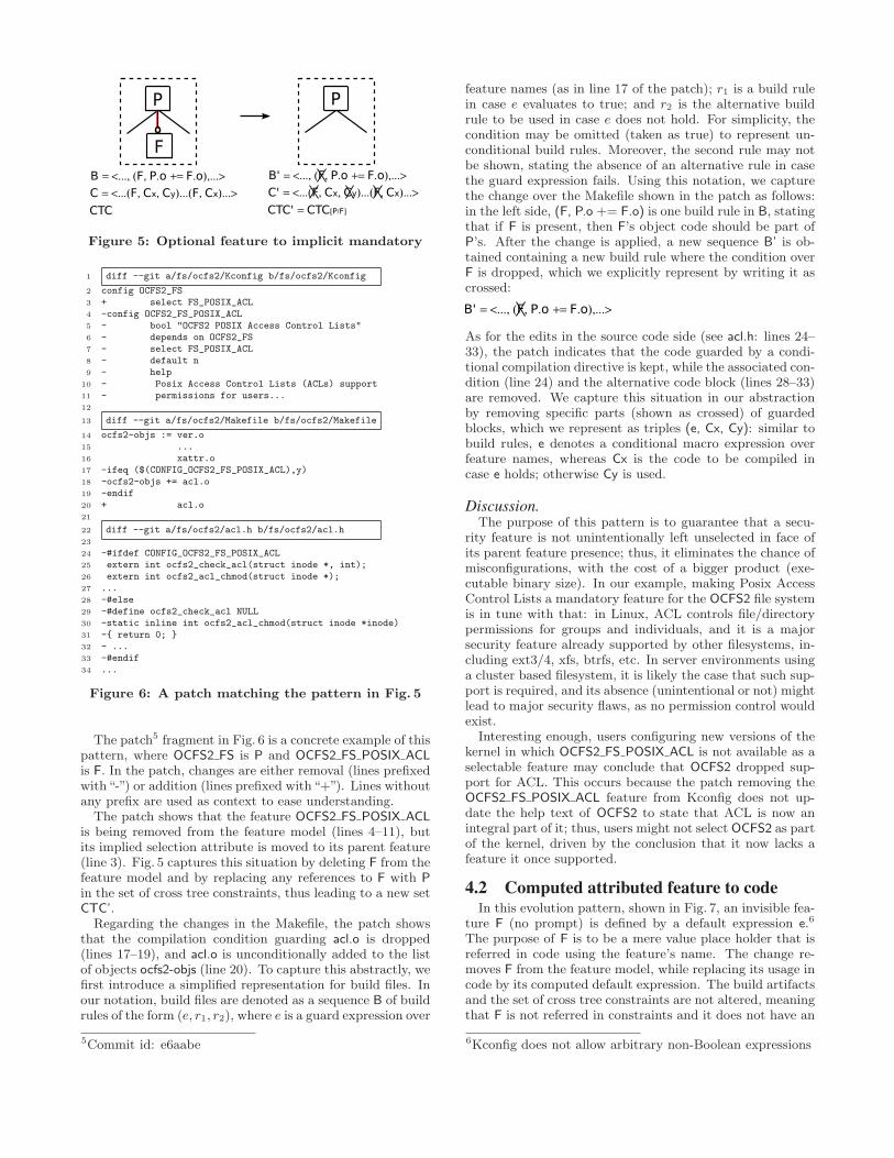
�
��= <..., (�, �.��+= �.�),...>��= <...(�, ��, �)...(�, ��)...>���
�
�
���= <..., (�, �.��+= �.�),...>���= <...(�, ��, �)...(�, ��)...>����= ��[�/�]
Figure 5: Optional feature to implicit mandatory
1 diff --git a/fs/ocfs2/Kconfig b/fs/ocfs2/Kconfig
2 config OCFS2_FS3 + select FS_POSIX_ACL4 -config OCFS2_FS_POSIX_ACL5 - bool "OCFS2 POSIX Access Control Lists"6 - depends on OCFS2_FS7 - select FS_POSIX_ACL8 - default n9 - help
10 - Posix Access Control Lists (ACLs) support11 - permissions for users...12
13 diff --git a/fs/ocfs2/Makefile b/fs/ocfs2/Makefile
14 ocfs2-objs := ver.o15 ...16 xattr.o17 -ifeq ($(CONFIG_OCFS2_FS_POSIX_ACL),y)18 -ocfs2-objs += acl.o19 -endif20 + acl.o21
22 diff --git a/fs/ocfs2/acl.h b/fs/ocfs2/acl.h23
24 -#ifdef CONFIG_OCFS2_FS_POSIX_ACL25 extern int ocfs2_check_acl(struct inode *, int);26 extern int ocfs2_acl_chmod(struct inode *);27 ...28 -#else29 -#define ocfs2_check_acl NULL30 -static inline int ocfs2_acl_chmod(struct inode *inode)31 -{ return 0; }32 - ...33 -#endif34 ...
Figure 6: A patch matching the pattern in Fig. 5
The patch5 fragment in Fig. 6 is a concrete example of thispattern, where OCFS2 FS is P and OCFS2 FS POSIX ACLis F. In the patch, changes are either removal (lines prefixedwith“-”) or addition (lines prefixed with“+”). Lines withoutany prefix are used as context to ease understanding.
The patch shows that the feature OCFS2 FS POSIX ACLis being removed from the feature model (lines 4–11), butits implied selection attribute is moved to its parent feature(line 3). Fig. 5 captures this situation by deleting F from thefeature model and by replacing any references to F with Pin the set of cross tree constraints, thus leading to a new setCTC’.
Regarding the changes in the Makefile, the patch showsthat the compilation condition guarding acl.o is dropped(lines 17–19), and acl.o is unconditionally added to the listof objects ocfs2-objs (line 20). To capture this abstractly, wefirst introduce a simplified representation for build files. Inour notation, build files are denoted as a sequence B of buildrules of the form (e, r1, r2), where e is a guard expression over
5Commit id: e6aabe
feature names (as in line 17 of the patch); r1 is a build rulein case e evaluates to true; and r2 is the alternative buildrule to be used in case e does not hold. For simplicity, thecondition may be omitted (taken as true) to represent un-conditional build rules. Moreover, the second rule may notbe shown, stating the absence of an alternative rule in casethe guard expression fails. Using this notation, we capturethe change over the Makefile shown in the patch as follows:in the left side, (F, P.o += F.o) is one build rule in B, statingthat if F is present, then F’s object code should be part ofP’s. After the change is applied, a new sequence B’ is ob-tained containing a new build rule where the condition overF is dropped, which we explicitly represent by writing it ascrossed:
���= <..., (�, �.��+= �.�),...>
As for the edits in the source code side (see acl.h: lines 24–33), the patch indicates that the code guarded by a condi-tional compilation directive is kept, while the associated con-dition (line 24) and the alternative code block (lines 28–33)are removed. We capture this situation in our abstractionby removing specific parts (shown as crossed) of guardedblocks, which we represent as triples (e, Cx, Cy): similar tobuild rules, e denotes a conditional macro expression overfeature names, whereas Cx is the code to be compiled incase e holds; otherwise Cy is used.
Discussion.The purpose of this pattern is to guarantee that a secu-
rity feature is not unintentionally left unselected in face ofits parent feature presence; thus, it eliminates the chance ofmisconfigurations, with the cost of a bigger product (exe-cutable binary size). In our example, making Posix AccessControl Lists a mandatory feature for the OCFS2 file systemis in tune with that: in Linux, ACL controls file/directorypermissions for groups and individuals, and it is a majorsecurity feature already supported by other filesystems, in-cluding ext3/4, xfs, btrfs, etc. In server environments usinga cluster based filesystem, it is likely the case that such sup-port is required, and its absence (unintentional or not) mightlead to major security flaws, as no permission control wouldexist.
Interesting enough, users configuring new versions of thekernel in which OCFS2 FS POSIX ACL is not available as aselectable feature may conclude that OCFS2 dropped sup-port for ACL. This occurs because the patch removing theOCFS2 FS POSIX ACL feature from Kconfig does not up-date the help text of OCFS2 to state that ACL is now anintegral part of it; thus, users might not select OCFS2 as partof the kernel, driven by the conclusion that it now lacks afeature it once supported.
4.2 Computed attributed feature to codeIn this evolution pattern, shown in Fig. 7, an invisible fea-
ture F (no prompt) is defined by a default expression e.6
The purpose of F is to be a mere value place holder that isreferred in code using the feature’s name. The change re-moves F from the feature model, while replacing its usage incode by its computed default expression. The build artifactsand the set of cross tree constraints are not altered, meaningthat F is not referred in constraints and it does not have an
6Kconfig does not allow arbitrary non-Boolean expressions
65
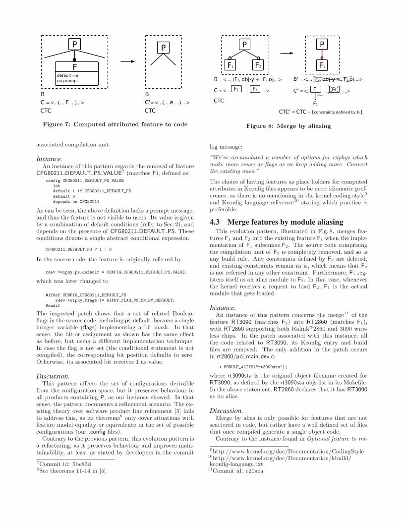
�
�
����= <...(... ��...)...>����
��� ��= ���������
�
��� ���= <...(... �...) ...>�����
Figure 7: Computed attributed feature to code
associated compilation unit.
Instance.An instance of this pattern regards the removal of feature
CFG80211 DEFAULT PS VALUE7 (matches F), defined as:config CFG80211_DEFAULT_PS_VALUE
intdefault 1 if CFG80211_DEFAULT_PSdefault 0depends on CFG80211
As can be seen, the above definition lacks a prompt message,and thus the feature is not visible to users. Its value is givenby a combination of default conditions (refer to Sec. 2), anddepends on the presence of CFG80211 DEFAULT PS. Theseconditions denote a single abstract conditional expression
CFG80211_DEFAULT_PS ? 1 : 0
In the source code, the feature is originally referred by
rdev->wiphy.ps_default = CONFIG_CFG80211_DEFAULT_PS_VALUE;
which was later changed to
#ifdef CONFIG_CFG80211_DEFAULT_PSrdev->wiphy.flags |= WIPHY_FLAG_PS_ON_BY_DEFAULT;
#endif
The inspected patch shows that a set of related Booleanflags in the source code, including ps default, became a singleinteger variable (flags) implementing a bit mask. In thatsense, the bit-or assignment as shown has the same effectas before, but using a different implementation technique.In case the flag is not set (the conditional statement is notcompiled), the corresponding bit position defaults to zero.Otherwise, its associated bit receives 1 as value.
Discussion.This pattern affects the set of configurations derivable
from the configuration space, but it preserves behaviour inall products containing P, as our instance showed. In thatsense, the pattern documents a refinement scenario. The ex-isting theory over software product line refinement [5] failsto address this, as its theorems8 only cover situations withfeature model equality or equivalence in the set of possibleconfigurations (our .config files).
Contrary to the previous pattern, this evolution pattern isa refactoring, as it preserves behaviour and improves main-tainability, at least as stated by developers in the commit
7Commit id: 5be83d8See theorems 11-14 in [5].
�
��= <..., (�2, ������+= �2.�),...>
��= <... ... ...>
���
�1
�2 �1
�1 �2 ���= <... ... ...>�1 �2
���= <..., (�2, ������+= �2.�),...>
����= �����{��� ������ ������������2} �2
�������
Figure 8: Merge by aliasing
log message:
“We’ve accumulated a number of options for wiphys whichmake more sense as flags as we keep adding more. Convertthe existing ones.”
The choice of having features as place holders for computedattributes in Kconfig files appears to be mere idiomatic pref-erence, as there is no mentioning in the kernel coding style9
and Kconfig language reference10 stating which practice ispreferable.
4.3 Merge features by module aliasingThis evolution pattern, illustrated in Fig. 8, merges fea-
tures F1 and F2 into the existing feature F1 when the imple-mentation of F1 subsumes F2. The source code comprisingthe compilation unit of F2 is completely removed, and so isany build rule. Any constraints defined by F2 are deleted,and existing constraints remain as is, which means that F2
is not referred in any other constraint. Furthermore, F1 reg-isters itself as an alias module to F2. In that case, wheneverthe kernel receives a request to load F2, F1 is the actualmodule that gets loaded.
Instance.An instance of this pattern concerns the merge11 of the
feature RT3090 (matches F2) into RT2860 (matches F1),with RT2860 supporting both Ralink™2860 and 3090 wire-less chips. In the patch associated with this instance, allthe code related to RT3090, its Kconfig entry and buildfiles are removed. The only addition in the patch occursin rt2860/pci main dev.c:
+ MODULE_ALIAS("rt3090sta");
where rt3090sta is the original object filename created forRT3090, as defined by the rt3090sta-objs list in its Makefile.In the above statement, RT2860 declares that it has RT3090as its alias.
Discussion.Merge by alias is only possible for features that are not
scattered in code, but rather have a well defined set of filesthat once compiled generate a single object code.
Contrary to the instance found in Optional feature to im-
9http://www.kernel.org/doc/Documentation/CodingStyle10http://www.kernel.org/doc/Documentation/kbuild/kconfig-language.txt
11Commit id: e20aea
66
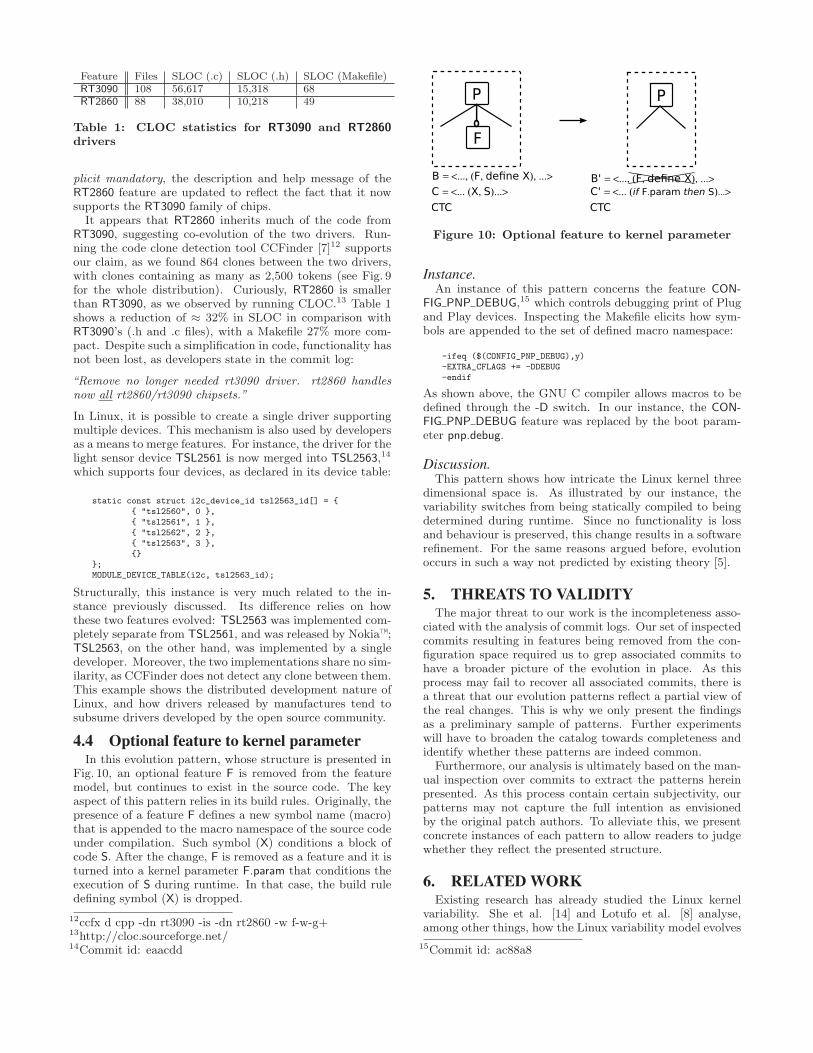
Feature Files SLOC (.c) SLOC (.h) SLOC (Makefile)RT3090 108 56,617 15,318 68RT2860 88 38,010 10,218 49
Table 1: CLOC statistics for RT3090 and RT2860drivers
plicit mandatory, the description and help message of theRT2860 feature are updated to reflect the fact that it nowsupports the RT3090 family of chips.
It appears that RT2860 inherits much of the code fromRT3090, suggesting co-evolution of the two drivers. Run-ning the code clone detection tool CCFinder [7]12 supportsour claim, as we found 864 clones between the two drivers,with clones containing as many as 2,500 tokens (see Fig. 9for the whole distribution). Curiously, RT2860 is smallerthan RT3090, as we observed by running CLOC.13 Table 1shows a reduction of ≈ 32% in SLOC in comparison withRT3090’s (.h and .c files), with a Makefile 27% more com-pact. Despite such a simplification in code, functionality hasnot been lost, as developers state in the commit log:
“Remove no longer needed rt3090 driver. rt2860 handlesnow all rt2860/rt3090 chipsets.”
In Linux, it is possible to create a single driver supportingmultiple devices. This mechanism is also used by developersas a means to merge features. For instance, the driver for thelight sensor device TSL2561 is now merged into TSL2563,14
which supports four devices, as declared in its device table:
static const struct i2c_device_id tsl2563_id[] = {{ "tsl2560", 0 },{ "tsl2561", 1 },{ "tsl2562", 2 },{ "tsl2563", 3 },{}
};MODULE_DEVICE_TABLE(i2c, tsl2563_id);
Structurally, this instance is very much related to the in-stance previously discussed. Its difference relies on howthese two features evolved: TSL2563 was implemented com-pletely separate from TSL2561, and was released by Nokia™;TSL2563, on the other hand, was implemented by a singledeveloper. Moreover, the two implementations share no sim-ilarity, as CCFinder does not detect any clone between them.This example shows the distributed development nature ofLinux, and how drivers released by manufactures tend tosubsume drivers developed by the open source community.
4.4 Optional feature to kernel parameterIn this evolution pattern, whose structure is presented in
Fig. 10, an optional feature F is removed from the featuremodel, but continues to exist in the source code. The keyaspect of this pattern relies in its build rules. Originally, thepresence of a feature F defines a new symbol name (macro)that is appended to the macro namespace of the source codeunder compilation. Such symbol (X) conditions a block ofcode S. After the change, F is removed as a feature and it isturned into a kernel parameter F.param that conditions theexecution of S during runtime. In that case, the build ruledefining symbol (X) is dropped.
12ccfx d cpp -dn rt3090 -is -dn rt2860 -w f-w-g+13http://cloc.sourceforge.net/14Commit id: eaacdd
��= <..., (�, �������), ...> ��= <... (�, �)...>���
�
���= <... (����.� � ��������)...>���
���= <..., (�, �������), ...>
Figure 10: Optional feature to kernel parameter
Instance.An instance of this pattern concerns the feature CON-
FIG PNP DEBUG,15 which controls debugging print of Plugand Play devices. Inspecting the Makefile elicits how sym-bols are appended to the set of defined macro namespace:
-ifeq ($(CONFIG_PNP_DEBUG),y)-EXTRA_CFLAGS += -DDEBUG-endif
As shown above, the GNU C compiler allows macros to bedefined through the -D switch. In our instance, the CON-FIG PNP DEBUG feature was replaced by the boot param-eter pnp.debug.
Discussion.This pattern shows how intricate the Linux kernel three
dimensional space is. As illustrated by our instance, thevariability switches from being statically compiled to beingdetermined during runtime. Since no functionality is lossand behaviour is preserved, this change results in a softwarerefinement. For the same reasons argued before, evolutionoccurs in such a way not predicted by existing theory [5].
5. THREATS TO VALIDITYThe major threat to our work is the incompleteness asso-
ciated with the analysis of commit logs. Our set of inspectedcommits resulting in features being removed from the con-figuration space required us to grep associated commits tohave a broader picture of the evolution in place. As thisprocess may fail to recover all associated commits, there isa threat that our evolution patterns reflect a partial view ofthe real changes. This is why we only present the findingsas a preliminary sample of patterns. Further experimentswill have to broaden the catalog towards completeness andidentify whether these patterns are indeed common.
Furthermore, our analysis is ultimately based on the man-ual inspection over commits to extract the patterns hereinpresented. As this process contain certain subjectivity, ourpatterns may not capture the full intention as envisionedby the original patch authors. To alleviate this, we presentconcrete instances of each pattern to allow readers to judgewhether they reflect the presented structure.
6. RELATED WORKExisting research has already studied the Linux kernel
variability. She et al. [14] and Lotufo et al. [8] analyse,among other things, how the Linux variability model evolves
15Commit id: ac88a8
67
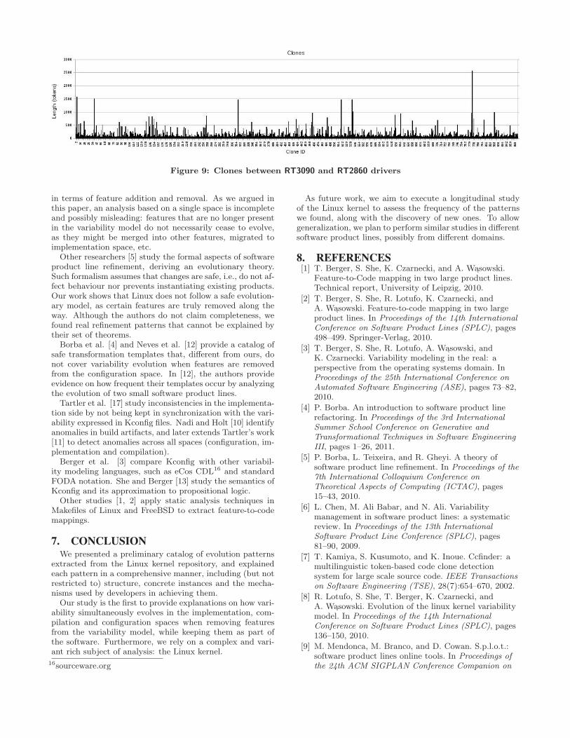
Figure 9: Clones between RT3090 and RT2860 drivers
in terms of feature addition and removal. As we argued inthis paper, an analysis based on a single space is incompleteand possibly misleading: features that are no longer presentin the variability model do not necessarily cease to evolve,as they might be merged into other features, migrated toimplementation space, etc.
Other researchers [5] study the formal aspects of softwareproduct line refinement, deriving an evolutionary theory.Such formalism assumes that changes are safe, i.e., do not af-fect behaviour nor prevents instantiating existing products.Our work shows that Linux does not follow a safe evolution-ary model, as certain features are truly removed along theway. Although the authors do not claim completeness, wefound real refinement patterns that cannot be explained bytheir set of theorems.
Borba et al. [4] and Neves et al. [12] provide a catalog ofsafe transformation templates that, different from ours, donot cover variability evolution when features are removedfrom the configuration space. In [12], the authors provideevidence on how frequent their templates occur by analyzingthe evolution of two small software product lines.
Tartler et al. [17] study inconsistencies in the implementa-tion side by not being kept in synchronization with the vari-ability expressed in Kconfig files. Nadi and Holt [10] identifyanomalies in build artifacts, and later extends Tartler’s work[11] to detect anomalies across all spaces (configuration, im-plementation and compilation).
Berger et al. [3] compare Kconfig with other variabil-ity modeling languages, such as eCos CDL16 and standardFODA notation. She and Berger [13] study the semantics ofKconfig and its approximation to propositional logic.
Other studies [1, 2] apply static analysis techniques inMakefiles of Linux and FreeBSD to extract feature-to-codemappings.
7. CONCLUSIONWe presented a preliminary catalog of evolution patterns
extracted from the Linux kernel repository, and explainedeach pattern in a comprehensive manner, including (but notrestricted to) structure, concrete instances and the mecha-nisms used by developers in achieving them.
Our study is the first to provide explanations on how vari-ability simultaneously evolves in the implementation, com-pilation and configuration spaces when removing featuresfrom the variability model, while keeping them as part ofthe software. Furthermore, we rely on a complex and vari-ant rich subject of analysis: the Linux kernel.
16sourceware.org
As future work, we aim to execute a longitudinal studyof the Linux kernel to assess the frequency of the patternswe found, along with the discovery of new ones. To allowgeneralization, we plan to perform similar studies in differentsoftware product lines, possibly from different domains.
8. REFERENCES[1] T. Berger, S. She, K. Czarnecki, and A. W ↪asowski.
Feature-to-Code mapping in two large product lines.Technical report, University of Leipzig, 2010.
[2] T. Berger, S. She, R. Lotufo, K. Czarnecki, andA. W ↪asowski. Feature-to-code mapping in two largeproduct lines. In Proceedings of the 14th InternationalConference on Software Product Lines (SPLC), pages498–499. Springer-Verlag, 2010.
[3] T. Berger, S. She, R. Lotufo, A. W ↪asowski, andK. Czarnecki. Variability modeling in the real: aperspective from the operating systems domain. InProceedings of the 25th International Conference onAutomated Software Engineering (ASE), pages 73–82,2010.
[4] P. Borba. An introduction to software product linerefactoring. In Proceedings of the 3rd InternationalSummer School Conference on Generative andTransformational Techniques in Software EngineeringIII, pages 1–26, 2011.
[5] P. Borba, L. Teixeira, and R. Gheyi. A theory ofsoftware product line refinement. In Proceedings of the7th International Colloquium Conference onTheoretical Aspects of Computing (ICTAC), pages15–43, 2010.
[6] L. Chen, M. Ali Babar, and N. Ali. Variabilitymanagement in software product lines: a systematicreview. In Proceedings of the 13th InternationalSoftware Product Line Conference (SPLC), pages81–90, 2009.
[7] T. Kamiya, S. Kusumoto, and K. Inoue. Ccfinder: amultilinguistic token-based code clone detectionsystem for large scale source code. IEEE Transactionson Software Engineering (TSE), 28(7):654–670, 2002.
[8] R. Lotufo, S. She, T. Berger, K. Czarnecki, andA. W ↪asowski. Evolution of the linux kernel variabilitymodel. In Proceedings of the 14th InternationalConference on Software Product Lines (SPLC), pages136–150, 2010.
[9] M. Mendonca, M. Branco, and D. Cowan. S.p.l.o.t.:software product lines online tools. In Proceedings ofthe 24th ACM SIGPLAN Conference Companion on
68
Object Oriented Programming Systems Languages andApplications (OOPSLA), pages 761–762, 2009.
[10] S. Nadi and R. Holt. Make it or break it: Mininganomalies from linux kbuild. In Proceedings of the2011 18th Working Conference on ReverseEngineering (WCRE), pages 315–324, 2011.
[11] S. Nadi and R. Holt. Mining kbuild to detectvariability anomalies in linux. European Conference onSoftware Maintenance and Reengineering (CSMR),pages 107–116, 2012.
[12] L. Neves, L. Teixeira, D. Sena, V. Alves, U. Kulezsa,and P. Borba. Investigating the safe evolution ofsoftware product lines. In Proceedings of the 10thACM International Conference on GenerativeProgramming and Component Engineering (GPCE),pages 33–42, New York, NY, USA, 2011. ACM.
[13] S. She and T. Berger. Formal semantics of the kconfiglanguage. Technical note, University of Waterloo,2010.
[14] S. She, R. Lotufo, T. Berger, A. Wasowski, andK. Czarnecki. The variability model of the linuxkernel. In In Proceedings of the 4th InternationalWorkshop on Variability Modelling ofSoftware-intensive Systems (VaMos), pages 45–51,2010.
[15] J. Sincero, H. Schirmeier, W. Schroder-Preikschat,and O. Spinczyk. Is the linux kernel a softwareproduct line? In Proceedings of the InternationalWorkshop on Open Source Software and Product Lines(OSSPL), 2007.
[16] R. Stallman, R. McGrath, and P. D. Smith. Gnu makemanual, 2010.
[17] R. Tartler, J. Sincero, C. Dietrich,W. Schroder-Preikschat, and D. Lohmann. Revealingand repairing configuration inconsistencies inlarge-scale system software. International Journal onSoftware Tools for Technology Transfer (STTT), pages1–21, 2012.
69
Challenges in the Evolution of Model-Based SoftwareProduct Lines in the Automotive Domain
Hannes HoldschickDaimler AG
Wilhelm-Runge-Str. 1189081 Ulm, Germany
ABSTRACTUsing the methodology of software product lines, it is pos-sible to generate program variants with a common core andadditional variable modules. Feature-based variant manage-ment is especially suitable for documenting differences andsimilarities of such variants. A variant model created ini-tially quickly becomes obsolete because of the permanentevolution of software functionalities in the automotive area.This is why we need a comprehensive concept how to handleevolution in variant-rich model-based software systems.
In order to achieve this, an exact understanding of theevolution of implementation artifacts is necessary in orderto be able to adjust variant modeling for the most importantchange cases beforehand. This work presents a collectionof relevant changes in a functional block model with thenecessary adaptation of the variant model.
Categories and Subject DescriptorsD.2.7 [Distribution, Maintenance, and Enhancement]:Restructuring, reverse engineering, and reengineering; D.2.13[Reusable Software]: Domain Engineering
General TermsDesign
1. INTRODUCTIONThe increase in vehicle and functional diversity in the
automotive industry leads to an elevated variant complex-ity of the software systems involved. The concept of soft-ware product lines supports the development and masteryof variant-rich, software-based systems [3]. The functionalproperties of these systems can be expressed using features[6].
In this paper we are concentrating on software variabil-ity in model-based function development. In this process, afunctional block model will be created which we call a func-tional model from now on. If the variability reaches a suf-
Permission to make digital or hard copies of all or part of this work forpersonal or classroom use is granted without fee provided that copies arenot made or distributed for profit or commercial advantage and that copiesbear this notice and the full citation on the first page. To copy otherwise, torepublish, to post on servers or to redistribute to lists, requires prior specificpermission and/or a fee.FOSD’12, September 24–25, 2012, Dresden, Germany.Copyright 2012 ACM 978-1-4503-1309-4/12/09 ...$15.00.
ficient complexity in a functional model, it should be docu-mented externally in a variant model. A widespread methodfor this is the feature model [6]. Additionally the configu-ration knowledge, namely a mapping between features andimplementation artifacts, is important for building systemvariants. In our approach the variant model consists of afeature model and the configuration knowledge.
If a variant model is created, it exists simultaneously nextto the functional model, which is subject to constant evo-lution. Therefore one of the fundamental properties of thevariant model is maintainability. Our definition of the termis based on the ISO guideline 9126 on software quality [5]:
Definition 1. The maintainability of a variant modeldescribes its ability to be modified. This includes correc-tions, improvements, or adaptations of the model to envi-ronmental changes.
Considering this definition we can derive quality criterialike easily recognized patterns, understandable structures forrules and dependencies, or small risk for an inconsistent orincorrect model after a change. Which of these propertiescontributes more or less to the maintainability of the vari-ant model depends on which type of change to the model iscommon or is understood as complicated. This is why wewant to get an overview of which changes relevant to vari-ability could occur in the functional model and where thechallenges are when reproducing them in the variant model.
Section 2 describes the important artifacts in this processand section 3 lists three examples of evolutionary changecases in the functional model. The driver assistence systemis our example of an evolutionary functionality.
2. FUNDAMENTALSIn this section we describe the structures of feature-ori-
ented software development which are important to us.
2.1 Functional ModelsOur considerations on the variability in the implementa-
tion domain are based on a model-based functional develop-ment approach, as it is known through Matlab / Simulink,Ascet, or similar tools. Accordingly, our functional modelcan be segmented into a set of components, which are hier-archically structured.
Various mechanisms exist in order to accommodate vari-ability in a component-based model, for example the 150%-approach or delta-oriented programming [8]. Nonetheless,all methods have in common that variation points in themodel must be created. This is why we are taking a closer
70
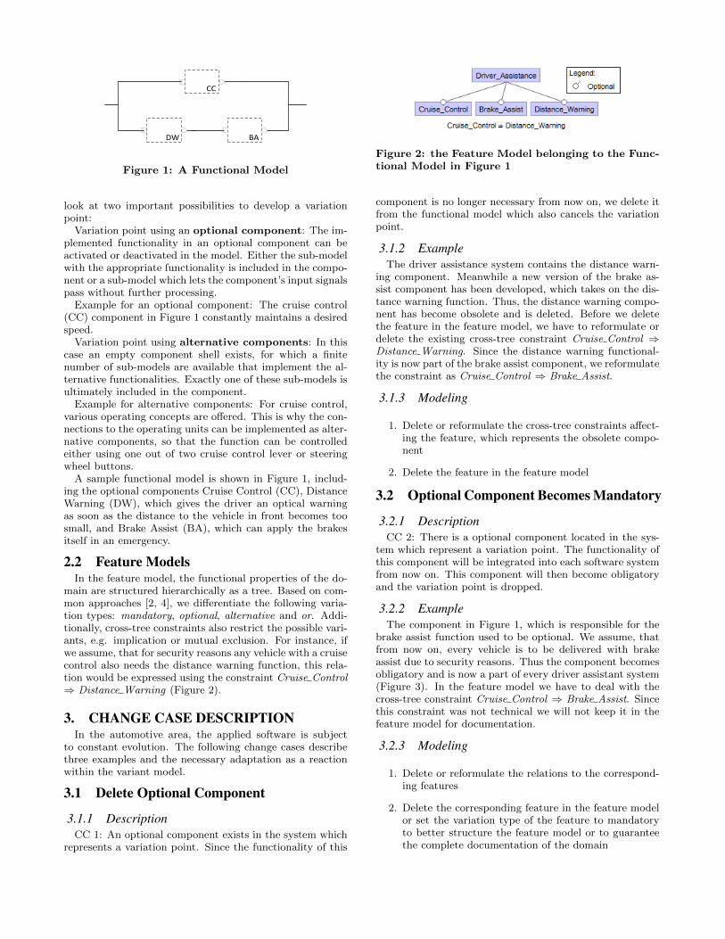
CC
BADW
Figure 1: A Functional Model
look at two important possibilities to develop a variationpoint:
Variation point using an optional component: The im-plemented functionality in an optional component can beactivated or deactivated in the model. Either the sub-modelwith the appropriate functionality is included in the compo-nent or a sub-model which lets the component’s input signalspass without further processing.
Example for an optional component: The cruise control(CC) component in Figure 1 constantly maintains a desiredspeed.
Variation point using alternative components: In thiscase an empty component shell exists, for which a finitenumber of sub-models are available that implement the al-ternative functionalities. Exactly one of these sub-models isultimately included in the component.
Example for alternative components: For cruise control,various operating concepts are offered. This is why the con-nections to the operating units can be implemented as alter-native components, so that the function can be controlledeither using one out of two cruise control lever or steeringwheel buttons.
A sample functional model is shown in Figure 1, includ-ing the optional components Cruise Control (CC), DistanceWarning (DW), which gives the driver an optical warningas soon as the distance to the vehicle in front becomes toosmall, and Brake Assist (BA), which can apply the brakesitself in an emergency.
2.2 Feature ModelsIn the feature model, the functional properties of the do-
main are structured hierarchically as a tree. Based on com-mon approaches [2, 4], we differentiate the following varia-tion types: mandatory, optional, alternative and or. Addi-tionally, cross-tree constraints also restrict the possible vari-ants, e.g. implication or mutual exclusion. For instance, ifwe assume, that for security reasons any vehicle with a cruisecontrol also needs the distance warning function, this rela-tion would be expressed using the constraint Cruise Control⇒ Distance Warning (Figure 2).
3. CHANGE CASE DESCRIPTIONIn the automotive area, the applied software is subject
to constant evolution. The following change cases describethree examples and the necessary adaptation as a reactionwithin the variant model.
3.1 Delete Optional Component
3.1.1 DescriptionCC 1: An optional component exists in the system which
represents a variation point. Since the functionality of this
Figure 2: the Feature Model belonging to the Func-tional Model in Figure 1
component is no longer necessary from now on, we delete itfrom the functional model which also cancels the variationpoint.
3.1.2 ExampleThe driver assistance system contains the distance warn-
ing component. Meanwhile a new version of the brake as-sist component has been developed, which takes on the dis-tance warning function. Thus, the distance warning compo-nent has become obsolete and is deleted. Before we deletethe feature in the feature model, we have to reformulate ordelete the existing cross-tree constraint Cruise Control ⇒Distance Warning. Since the distance warning functional-ity is now part of the brake assist component, we reformulatethe constraint as Cruise Control ⇒ Brake Assist.
3.1.3 Modeling
1. Delete or reformulate the cross-tree constraints affect-ing the feature, which represents the obsolete compo-nent
2. Delete the feature in the feature model
3.2 Optional Component Becomes Mandatory
3.2.1 DescriptionCC 2: There is a optional component located in the sys-
tem which represent a variation point. The functionality ofthis component will be integrated into each software systemfrom now on. This component will then become obligatoryand the variation point is dropped.
3.2.2 ExampleThe component in Figure 1, which is responsible for the
brake assist function used to be optional. We assume, thatfrom now on, every vehicle is to be delivered with brakeassist due to security reasons. Thus the component becomesobligatory and is now a part of every driver assistant system(Figure 3). In the feature model we have to deal with thecross-tree constraint Cruise Control ⇒ Brake Assist. Sincethis constraint was not technical we will not keep it in thefeature model for documentation.
3.2.3 Modeling
1. Delete or reformulate the relations to the correspond-ing features
2. Delete the corresponding feature in the feature modelor set the variation type of the feature to mandatoryto better structure the feature model or to guaranteethe complete documentation of the domain
71
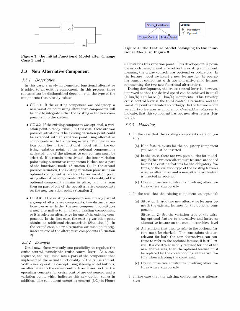
CC
BA
Figure 3: the initial Functional Model after ChangeCase 1 and 2
3.3 New Alternative Component
3.3.1 DescriptionIn this case, a newly implemented functional alternative
is added to an existing component. In this process, threesubcases can be distinguished depending on the type of thecomponents that already existed.
• CC 3.1: If the existing component was obligatory, anew variation point using alternative components willbe able to integrate either the existing or the new com-ponents into the system.
• CC 3.2: If the existing component was optional, a vari-ation point already exists. In this case, there are twopossible situations. The existing variation point couldbe extended with an variation point using alternativecomponents so that a nesting occurs. The new varia-tion point lies in the functional model within the ex-isting variation point. If the optional component isactivated, one of the alternative components must beselected. If it remains deactivated, the inner variationpoint using alternative components is then not a partof the functional model (Situation 1). In the secondpossible situation, the existing variation point using anoptional component is replaced by an variation pointusing alternative components. The functionality of theoptional component remains in place, but it is fromthen on part of one of the two alternative componentson the new variation point (Situation 2).
• CC 3.3: If the existing component was already part ofa group of alternative components, two distinct situa-tions can arise. Either the new component constitutesa new alternative to all already existing components,or it is solely an alternative for one of the existing com-ponents. In the first case, the existing variation pointobtains an additional characteristic (Situation 1). Inthe second case, a new alternative variation point orig-inates in one of the alternative components (Situation2).
3.3.2 ExampleUntil now, there was only one possibility to regulate the
cruise control, namely the cruise control lever. As a con-sequence, the regulation was a part of the component thatimplemented the actual functionality of the cruise control.With a new operating concept using steering wheel buttons,an alternative to the cruise control lever arises, so that theoperating concepts for cruise control are outsourced and avariation point, which indicates this new option, comes inaddition. The component operating concept (OC) in Figure
Figure 4: the Feature Model belonging to the Func-tional Model in Figure 3
5 illustrates this variation point. This development is possi-ble in both cases, no matter whether the existing component,meaning the cruise control, was optional or obligatory. Inthe feature model we insert a new feature for the operat-ing concept component with two alternative child featuresrepresenting the two new functional alternatives.
During development, the cruise control lever is, however,improved so that the desired speed can be achieved in small(1 km/h) and large (10 km/h) increments. This two-stepcruise control lever is the third control alternative and thevariation point is extended accordingly. In the feature modelwe add two features as children of Cruise Control Lever toindicate, that this component has two new alternatives (Fig-ure 6).
3.3.3 Modeling
1. In the case that the existing components were obliga-tory:
(a) If no feature exists for the obligatory componentyet, one must be inserted
(b) In this case, there are two possibilities for model-ing: Either two new alternative features are addedbelow the existing features for the obligatory fea-tures, or the variation type of the existing featuresis set as alternative and a new alternative featureis inserted in addition.
(c) Create cross-tree constraints involving other fea-tures where appropriate
2. In the case that the existing component was optional:
(a) Situation 1: Add two new alternative features be-neath the existing features for the optional com-ponents
Situation 2: Set the variation type of the exist-ing optional feature to alternative and insert analternative feature on the same hierarchical level
(b) All relations that used to refer to the optional fea-ture must be checked. The constraints that arerelevant for both the new alternatives can con-tinue to refer to the optional feature, if it still ex-ists. If a constraint is only relevant for one of thenew alternatives, then the optional feature mustbe replaced by the corresponding alternative fea-ture when adapting the constraint.
(c) Create cross-tree constraints involving other fea-tures where appropriate
3. In the case that the existing component was alterna-tive:
72
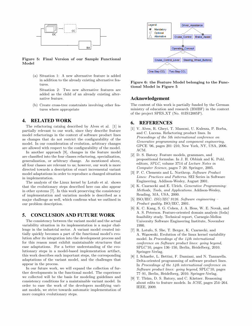
CC
BA
OC
Figure 5: Final Version of our Sample FunctionalModel
(a) Situation 1: A new alternative feature is addedin addition to the already existing alternative fea-tures.
Situation 2: Two new alternative features areadded as the child of an already existing alter-native feature.
(b) Create cross-tree constraints involving other fea-tures where appropriate
4. RELATED WORKThe refactoring catalog described by Alves et al. [1] is
partially relevant to our work, since they describe featuremodel refactorings in the context of software product linesas changes that do not restrict the configurability of themodel. In our consideration of evolution, arbitrary changesare allowed with respect to the configurability of the model.
In another approach [9], changes in the feature modelare classified into the four classes refactoring, specialization,generalization, or arbitrary change. As mentioned above,all four classes are relevant to us; however, our work is moredirected towards a description of exact incremental variantmodel adaptations in order to reproduce a changed situationin implementation.
The analysis of the Linux kernel by Lotufo et al. showsthat the evolutionary steps described here can also appearin other systems [7]. In this work preserving the consistencyof implementation and variation models is described as amajor challenge as well, which confirms what we outlined inour problem description.
5. CONCLUSION AND FUTURE WORKThe consistency between the variant model and the actual
variability situation in its implementation is a major chal-lenge in the industrial sector. A variant model created ini-tially quickly becomes a part of the functional model’s evo-lution after its integration into the development process andfor this reason must exhibit maintainable structures thatease adaptations. For a better understanding of the evo-lutionary steps in a model-based implementation artifact,this work describes such important steps, the correspondingadaptations of the variant model, and the challenges thatappear in the process.
In our future work, we will expand the collection of fur-ther developments in the functional model. The experiencewe collected will be the basis for modeling guidelines andconsistency conditions for a maintainable variant model. Inorder to ease the work of the developers modifying vari-ant models, we strive towards automatic implementation ofmore complex evolutionary steps.
Figure 6: the Feature Model belonging to the Func-tional Model in Figure 5
AcknowledgementThe content of this work is partially funded by the Germanministry of education and research (BMBF) in the contextof the project SPES XT (No. 01IS12005P).
6. REFERENCES[1] V. Alves, R. Gheyi, T. Massoni, U. Kulesza, P. Borba,
and C. Lucena. Refactoring product lines. InProceedings of the 5th international conference onGenerative programming and component engineering,GPCE ’06, pages 201–210, New York, NY, USA, 2006.ACM.
[2] D. S. Batory. Feature models, grammars, andpropositional formulas. In J. H. Obbink and K. Pohl,editors, SPLC, volume 3714 of Lecture Notes inComputer Science, pages 7–20. Springer, 2005.
[3] P. C. Clements and L. Northrop. Software ProductLines: Practices and Patterns. SEI Series in SoftwareEngineering. Addison-Wesley, August 2001.
[4] K. Czarnecki and E. Ulrich. Generative Programming:Methods, Tools, and Applications. Addison-Wesley,Reading, MA, USA, 2000.
[5] ISO/IEC. ISO/IEC 9126. Software engineering –Product quality. ISO/IEC, 2001.
[6] K. C. Kang, S. G. Cohen, J. A. Hess, W. E. Novak, andA. S. Peterson. Feature-oriented domain analysis (foda)feasibility study. Technical report, Carnegie-MellonUniversity Software Engineering Institute, November1990.
[7] R. Lotufo, S. She, T. Berger, K. Czarnecki, andA. W ↪asowski. Evolution of the linux kernel variabilitymodel. In Proceedings of the 14th internationalconference on Software product lines: going beyond,SPLC’10, pages 136–150, Berlin, Heidelberg, 2010.Springer-Verlag.
[8] I. Schaefer, L. Bettini, F. Damiani, and N. Tanzarella.Delta-oriented programming of software product lines.In Proceedings of the 14th international conference onSoftware product lines: going beyond, SPLC’10, pages77–91, Berlin, Heidelberg, 2010. Springer-Verlag.
[9] T. Thum, D. S. Batory, and C. Kastner. Reasoningabout edits to feature models. In ICSE, pages 254–264.IEEE, 2009.
73