Embed Size (px)
Citation preview
A SCIENCE AND TECHNOLOGY PUBLICATION
Volume 9 No. 2 Summer, 2000
Table ofContents
Cover Story
TABLE OF CONTENTS
INJ DEPARTMENTSGuest EditorialDirector's CornerEmerging TechnologyRsearcher's ToolboxWorldwide Abstracts
The Nonwovens NetAssociation NewsThe TAPPI PageUniversity FocusNonwovens Calendar 2000
International Nonwovens Journal Home Page
file:///D|/WWW/inda/subscrip/inj00_2/index.html (1 of 3) [3/14/2002 7:26:37 AM]
PAPERSQualitative Evaluation of Nonwoven Samples Using DuPont Fiber Identification Stain No. 4 andMicroscopyNonwovens Perspective by Michele Mlynar, Rohm & Haas.
Cotton-Surfaced Nonwovens For Short-Wear-Cycle ApparelOriginal Paper by Larry Wadsworth, Hannah Suh, The University of Tennessee;H. Charles Allen, Jr., Cotton Incorporated/INDA
Pore Size and Air Permeability of Four Nonwoven FabricsOriginal Paper by Helen H. Epps and Karen Leonas, The University of Georgia 18
Analysis of Roofing Mat StructureOriginal Paper by Randall Bresee, Hong Yin and Zanyao Yan, Textiles and Nonwovens DevelopmentCenter, The University of Tennessee
A Study of the Airflow and Fibre Dynamics in the Transport Chamber of a Sifting Air-Laying System.Part 1: Airflow CharacteristicsOriginal Paper by A. Pourmohammadi and S.J. Russell, Nonwovens Research Group, School ofTextile Industries; R. Bradean, D.B. Ingham and X. Wen, Centre for CFD, University of Leeds
Performance of Nonwoven Cellulosic Composites for Automotive InteriorsOriginal Paper by D.V. Parikh, T.A. Calamari, USDA, ARS, SRRC, and J.C. Myatt, JanesvilleProducts
Publisher Ted Wirtz PresidentINDA,Association of the Nonwoven Fabrics Industry
Sponsors Wayne Gross Executive Director/COOTAPPI, Technical Association of the Pulp and Paper Industry
Teruo YoshimuraSecretary GeneralANIC, Asia Nonwoven Fabrics Industry Conference
Editors Rob Johnson [email protected]
D.K. Smith [email protected]
Association Editor Chuck Allen INDA
D.V. Parikh TAPPI
Teruo Yoshimura ANIC
Production Editor Michael Jacobsen Jacor Publications, [email protected]
International Nonwovens Journal Home Page
file:///D|/WWW/inda/subscrip/inj00_2/index.html (2 of 3) [3/14/2002 7:26:37 AM]

Cover Photo courtesy of Rohm & Haas
The International Nonwovens Journal is published by INDA, Association of the Nonwoven Fabrics Industry, P.O. Box1288, Cary, NC 27512; www.inda.org. Copyright 2000 INDA, Association of the Nonwoven Fabrics Industry. No part of
this publication may be reproduced or transmitted in any form or by any means, electronic or mechanical, includingphotocopying and recording, or by any information storage or retrieval system, except as may be expressly permitted in
writing by the copyright owner. The magazine is sent free-of-charge to all members of INDA and TAPPI, P.O. Box105113, Atlanta, GA 30348; 404-209-727; Fax 404-446-6947; and ANNA (Asia Nonwoven Fabrics Industry Conference),
Soto kanda 6-Chome Bldg. 3Fl, 2-9, Chiyoda-ku, Tokyo, 101, Japan. The International Nonwovens Journal can not bereprinted without permission from INDA. INDA¨ is a registered trademark of INDA, Association of the Nonwoven
Fabrics Industry
International Nonwovens Journal Home Page
file:///D|/WWW/inda/subscrip/inj00_2/index.html (3 of 3) [3/14/2002 7:26:37 AM]
GUEST EDITORIAL
An Invitation To An Historic Nonwovens EventBy Peter Wallace, Business Manager, Nonwoven Resins, Borden Chemical; INTC 2000 ConferenceChairman
"Coming together is a beginning; Keeping together is progress; Working together is success." — HenryFord
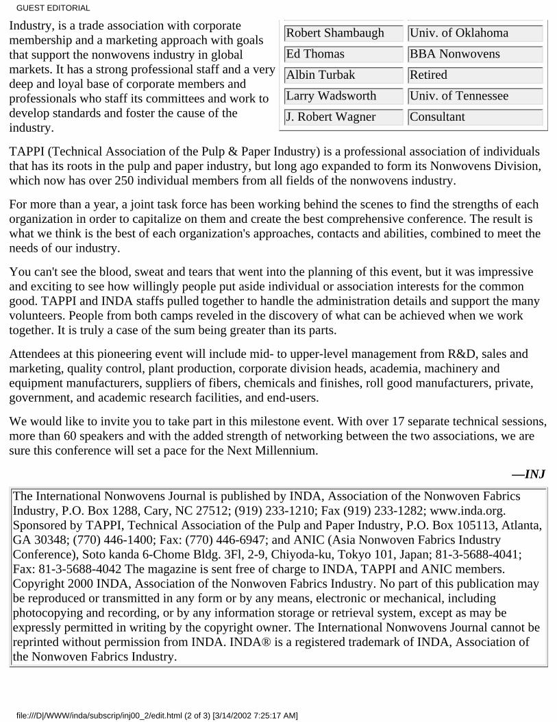
EDITORIAL ADVISORY BOARDChuck Allen INDA
Roy Broughton Auburn University
Robin Dent Albany International
Ed Engle Fibervisions
Tushar Ghosh NCSU
Bhuvenesh Goswami Clemson
Dale Grove Owens Corning
Frank Harris HDK Industries
Albert Hoyle Hoyle Associates
Marshall Hutten Hollingsworth & Vose
Hyun Lim E.I. duPont de Nemours
Joe Malik AQF Technologies
Alan Meierhoefer Dexter Nonwovens
Michele Mlynar Rohm and Haas
Graham Moore PIRA
D.V. Parikh U.S.D.A.–S.R.R.C.
Behnam Pourdeyhimi NCSU
Art Sampson Polymer Group Inc.
What better time than the dawn of a New
Millennium for us in the nonwoven industry to worktogether for success? I'm referring to theInternational Nonwovens Technical Conference2000 (INTC 2000), which will take place in Dallas,TX from September 26-28.
This marks a milestone for our industry — the firsttime that INDA and TAPPI are holding a jointnonwoven technical conference. These twoorganizations have long played valuable roles in thenonwovens industry, both in North America andglobally - but independently. Each sponsoredtechnical conferences, each taking advantage of itsown unique approach to the world of nonwovens.INDA has accomplished this with INDA-TEC,while TAPPI has held an annual NonwovensConference.
These two quality technical symposiums havegrown to overlap as technology has evolved. Itmakes sense, at the threshold of a new era for ourindustry, to combine both conferences into onemajor event - the INTC 2000.
INDA, Association of the Nonwoven Fabrics
GUEST EDITORIAL
file:///D|/WWW/inda/subscrip/inj00_2/edit.html (1 of 3) [3/14/2002 7:25:17 AM]
Robert Shambaugh Univ. of Oklahoma
Ed Thomas BBA Nonwovens
Albin Turbak Retired
Larry Wadsworth Univ. of Tennessee
J. Robert Wagner Consultant
Industry, is a trade association with corporatemembership and a marketing approach with goalsthat support the nonwovens industry in globalmarkets. It has a strong professional staff and a verydeep and loyal base of corporate members andprofessionals who staff its committees and work todevelop standards and foster the cause of theindustry.
TAPPI (Technical Association of the Pulp & Paper Industry) is a professional association of individualsthat has its roots in the pulp and paper industry, but long ago expanded to form its Nonwovens Division,which now has over 250 individual members from all fields of the nonwovens industry.
For more than a year, a joint task force has been working behind the scenes to find the strengths of eachorganization in order to capitalize on them and create the best comprehensive conference. The result iswhat we think is the best of each organization's approaches, contacts and abilities, combined to meet theneeds of our industry.
You can't see the blood, sweat and tears that went into the planning of this event, but it was impressiveand exciting to see how willingly people put aside individual or association interests for the commongood. TAPPI and INDA staffs pulled together to handle the administration details and support the manyvolunteers. People from both camps reveled in the discovery of what can be achieved when we worktogether. It is truly a case of the sum being greater than its parts.
Attendees at this pioneering event will include mid- to upper-level management from R&D, sales andmarketing, quality control, plant production, corporate division heads, academia, machinery andequipment manufacturers, suppliers of fibers, chemicals and finishes, roll good manufacturers, private,government, and academic research facilities, and end-users.
We would like to invite you to take part in this milestone event. With over 17 separate technical sessions,more than 60 speakers and with the added strength of networking between the two associations, we aresure this conference will set a pace for the Next Millennium.
—INJ
The International Nonwovens Journal is published by INDA, Association of the Nonwoven FabricsIndustry, P.O. Box 1288, Cary, NC 27512; (919) 233-1210; Fax (919) 233-1282; www.inda.org.Sponsored by TAPPI, Technical Association of the Pulp and Paper Industry, P.O. Box 105113, Atlanta,GA 30348; (770) 446-1400; Fax: (770) 446-6947; and ANIC (Asia Nonwoven Fabrics IndustryConference), Soto kanda 6-Chome Bldg. 3Fl, 2-9, Chiyoda-ku, Tokyo 101, Japan; 81-3-5688-4041;Fax: 81-3-5688-4042 The magazine is sent free of charge to INDA, TAPPI and ANIC members.Copyright 2000 INDA, Association of the Nonwoven Fabrics Industry. No part of this publication maybe reproduced or transmitted in any form or by any means, electronic or mechanical, includingphotocopying and recording, or by any information storage or retrieval system, except as may beexpressly permitted in writing by the copyright owner. The International Nonwovens Journal cannot bereprinted without permission from INDA. INDA® is a registered trademark of INDA, Association ofthe Nonwoven Fabrics Industry.
GUEST EDITORIAL
file:///D|/WWW/inda/subscrip/inj00_2/edit.html (2 of 3) [3/14/2002 7:25:17 AM]

Return to International Nonwovens JournalHome Page & Table of Contents
GUEST EDITORIAL
file:///D|/WWW/inda/subscrip/inj00_2/edit.html (3 of 3) [3/14/2002 7:25:17 AM]
Cover Photo courtesy of Rohm & Haas
The International Nonwovens Journal is published by INDA, Association of the Nonwoven Fabrics Industry, P.O. Box1288, Cary, NC 27512; www.inda.org. Copyright 2000 INDA, Association of the Nonwoven Fabrics Industry. No part of
this publication may be reproduced or transmitted in any form or by any means, electronic or mechanical, includingphotocopying and recording, or by any information storage or retrieval system, except as may be expressly permitted in
writing by the copyright owner. The magazine is sent free-of-charge to all members of INDA and TAPPI, P.O. Box105113, Atlanta, GA 30348; 404-209-727; Fax 404-446-6947; and ANNA (Asia Nonwoven Fabrics Industry Conference),
Soto kanda 6-Chome Bldg. 3Fl, 2-9, Chiyoda-ku, Tokyo, 101, Japan. The International Nonwovens Journal can not bereprinted without permission from INDA. INDA¨ is a registered trademark of INDA, Association of the Nonwoven
Fabrics Industry
International Nonwovens Journal Home Page
file:///D|/WWW/inda/subscrip/inj00_2/index.html (3 of 3) [3/14/2002 7:26:37 AM]
INJ DEPARTMENTS
THE DIRECTOR’S CORNERBuilding Team SavvyA popular concept of a scientist or engineer is that of a "loner" who works in isolation, with minimalcontact with the rest of society. In reality, today's major contributor to science and technology is amember of a team, working in an environment where the contributions from several individuals make forreal success and progress. Learning the skills of working within a group focused on a common goal is nota talent that comes at birth. It is a skill and ability that can be learned, however, and must be learned by agood team member.
One group in academia has recognized the importance of learning such skills and has taken some majorsteps to incorporate such know-how into an academic curriculum. As reported by Professor J. A.Kampmeier, of the University of Rochester, "The Workshop Project" for teaching such skills is one ofthe five national science foundation's Systemic Initiatives to educate students in the skills required forsuccess in industry. Dr. Kampmeier has provided the following explanation:
Since 1995, the project, headquartered at City College of New York, has explored and developed amodel of Peer-Led Team Learning (PLTL) to guide students to new understanding and accomplishmentin chemistry courses. Recently, the project was awarded a National Dissemination Grant to extend themodel to other science disciplines. The PLTL model is built on theoretical ideas about the way studentslearn and on practical experience that has shown that teams do work.
* Learning theory shows that the process of constructing individual understanding is facilitated by socialinteraction. Experience demonstrates that teams achieve remarkable levels of insight andaccomplishment by sharing different ideas and perspectives in pursuit of a common goal.
* In the PLTL model, teams of students meet weekly to solve challenging problems that are directlyrelated to mastering the subject matter. Each team has a leader, a peer who was successful in the courseand is trained to build a team of students who work effectively to learn. In 1998-99, more than 50 facultyand 300 leaders at more than 30 colleges and universities guided weekly PLTL workshops for 2,500students each semester.
The accumulated results from five years of experience are clear: Workshop students are more successfulthan traditional students in their chemistry courses. This increased success comes from the PLTLstructure that requires them to "get team savvy." To learn more, check out The Workshop Project Teamwebsite at www.sci.ccny.cuny.edu/~chemwksp)
The Director's Corner
file:///D|/WWW/inda/subscrip/inj00_2/direct.html (1 of 4) [3/14/2002 7:24:46 AM]
New Products DevelopmentThe paradigm of growing popularity within many companies is the necessity to shorten the productdevelopment path. This may mean the elimination of conventional test markets, as well as shortening thecycle of various stages.
For the research director, it generally means abbreviating the product development cycle and especiallyadopting strategies that facilitate new products development (NPD).
The Industrial Research Institute, a major professional association of research directors, recently formeda small study team to explore the role of research and development in the NPD process. The team set outto vilify the best NPD practices used by successful companies. They surveyed 383 U.S.-based companiesto measure the effectiveness and efficiency of innovation processes. The survey used a graded scale toassess the degree to which best practices have been adopted.
While the most successful companies differed somewhat in their approach to putting NPD principles intopractice, there appeared to five, guiding features:
Clarity - Management went to great length to insure that there was sufficient clarity andunderstanding throughout the organization to achieve the goals. This clarity was present at projectinitiation, but continued throughout the life of the project. The entire NPD group knew whatneeded to be done, by whom, when and how.
●
Ownership - Successful NPD activities were viewed as an enterprise-wide process rather than onethat was owned by the research group, marketing group or any other group. Top management tookpains to engage and integrate all people and resources within the organization that could contributeto successful commercialization of a new product.
●
Leadership - NPD activities must be strongly promoted and championed by top management.Opportunities for frequent reporting to the top must be created and involve various levels of theNPD task force. The satisfaction of successful completion of NPD must be shared, and awards andrecognition for NPD innovators were employed.
●
Integration - The NPD effort was integrated into all functions of the organization that could makea contribution. In addition, integration of key processes such as market assessment, portfoliomanagement, capital project management, product branding, ISO compliance or safety and hazardreviews were thoughtfully assured.
●
Flexibility - The organization and operation of the NPD process must be flexible enough to adjustto needs and desires. As feedback was obtained from lead customers, appropriate adjustments andadaptations were made quickly and with full communication.
●
The authors of this study pointed out that NPD must be viewed as an corporate-wide process rather thanbeing owned by any one function; they also pointed out that senior management must go beyondadvocacy to full engagement as sponsors of active participants of NPD. Additional information can beobtained from the website of Research-Technology Management at http://www.iriinc.org.v0000007.htm.
Recycling's DilemmaRecycling is a very old friend of the textile industry. As has been previously reported in this department,textiles have been recycled for decades. Some of this recycling was done within individual households,but a major portion involved collecting old rags in use in producing cotton-based paper products.
The Director's Corner
file:///D|/WWW/inda/subscrip/inj00_2/direct.html (2 of 4) [3/14/2002 7:24:46 AM]
Within the past couple of decades, the concept of recycling has become very fashionable. It is a majorelement of environmental concern. Within the textile industry, the Council for Textile Recycling hastaken on a major responsibility for this effort. The council is a non-profit (501-C-3 tax classification)educational foundation whose mission is to promote the importance of recycling textile materials andencourage the use of materials made from recycled textile materials. The council has carried out theirwork in two major areas:
The council municipalities and recycling organizations to promote the recycling of both pre-andpost-consumer waste materials. This includes household items as well as post-producer waste thatwould otherwise be landfilled.
●
For recycling to be successful there has to a market for these materials. The council promotes theuse of materials made from recycled textile products. Protecting and preserving our naturalresources is an important message of the council.
●
The nonwovens industry must applaud and support these efforts and is actually playing a significant rolein several areas and in a variety of market segments. Some of these market segments have been verysuccessful and profitable. Several successful companies within the industry have built their organizationsaround the use of secondary fiber and recycled products.
Despite these successes, several segments of the recycling system are in trouble. Some of this resultsfrom unrealistic goals that were established or forced upon segments of industry. The paper and plasticsindustries are particularly noteworthy in this respect. Anticipating the growth and expansion in the use ofrecycled paper products, many smaller de-inking mills were established close to metropolitan areas.
The waste paper flow from these areas was frequently referred to as "urban forests" and characterized asa cheap and reliable source of raw material. Unfortunately, the market for such fiber furnish quicklyoutstripped the supply. Despite efforts by industry and the Federal Government to encourage, and insome cases, enforce the use of the recycled paper, the market imbalance has resulted in the closure ofmany of these operations.
In too many instances, components of the household waste stream that were dutifully sorted by thehouseholder found their way into the landfill instead of a recycled application. The imbalance of supplyand demand, coupled with the realities of economic values, has resulted in many problems in anotherwise laudable effort.
There is a growing recognition that there are natural and market limits in the recycling of many materials.The Scientific and Research Institute TNO (Zeist, The Netherlands) has studied the recycling of plasticspackaging waste and has found that recycling more than 15% of this type of waste would be costly andhave limited economic benefit for European countries. The European Commission is pressuring thePlastics Institute to increase the portion of plastics waste that is recycled to more than 15%. However, thestudy indicates that increasing plastic recycling wastes from 15 to 50% would increase costs by a factorof 3, while the environmental impact would remain broadly similar.
Although the study focused solely on plastics packaging waste, it has been indicated that the study'sresults could be indicative of the situation for other plastic waste streams as well.
As a result, the sponsoring organization for this study says most plastic waste should be burned togenerate energy, instead of attempting to raise recycling to more than 15%. Also, the point is made thatplastics recycling should focus on post-industrial waste rather than post-consumer waste in this case.
The Director's Corner
file:///D|/WWW/inda/subscrip/inj00_2/direct.html (3 of 4) [3/14/2002 7:24:46 AM]
About 70% of European plastics wastes is landfilled, 15% is burned for energy recovery, 12% is recycledand 3% is recovered to produce chemical products. This study suggests that it would be morecost-effective and environmentally efficient to recycle 15% of plastics waste and recover 85% as energy.
While each waste material stream has its own situation, it is increasing apparent that recycling will workonly as it makes sense.
For more information, contact the Council for Textile Recycling, 7910 Woodmont Avenue, Suite 1130,Bethesda, MD 20814; 301-718-0671; Fax 301-756-1079; or www.textilerecycle.org
- INJ
Return to International Nonwovens JournalHome Page & Table of Contents
The Director's Corner
file:///D|/WWW/inda/subscrip/inj00_2/direct.html (4 of 4) [3/14/2002 7:24:46 AM]
INJ DEPARTMENTS
EMERGING TECHNOLOGY WATCHProtective Garments Under The SunProtective garments take many forms, as there are a great number of conditions from which protection isneeded. In actual fact, a baby's diaper is a protective garment; it protects mother, dad and theenvironment.
The total U.S. industrial protective garment market for all types is very substantial, amounting to about$595 billion in 1999. The growth rate (slightly over 4% per year), which has been driven by governmentregulations the past several years, has slowed somewhat in the past three years, as regulations have notchanged significantly.
A new type of protection is flirting with this market; this is the protection afforded by wearing apparelagainst the influence of sunlight. While the tremendous number of sunbathers doesn't seem to reflect it,there is a growing concern with excessive sunlight exposure, leading to the initiation and proliferation ofhuman skin cancer as well as some other problems. The expanding use of protective lotions with theirspecific sunlight protection factor (SPF) is a reflection of this concern.
Contrary to this concept, there is a school of thought that says the peeling of skin from a sunburn isbeneficial, as it gives a renewed layer of skin and disposes of the older layer. There is a considerable useof 9-fluorouracil to accomplish this condition chemically.
Despite the contradictory views, there is considerable activity with textiles to provide increased sunlightprotection.
Common sense would seem to indicate that textiles in general will give some shielding from damagingsunlight, and the more dense the fabric the better protection. Increasing fabric weight and thickness iscounter to the prevailing desire in clothing, however, especially in athletic clothing. Thus, the growingtechnology in the sunlight protective action of apparel.
Research indicates there is a difference in the various dyestuffs used to color fabrics. Simple black is notnecessarily the best protection. In fact, some of dyestuff concerns are conducting extensive research intothe value of various materials; some companies are beginning to offer products specifically selected fortheir protection potential.
One company, Ciba Specialty Chemicals, is seeking recognition from the Skin Cancer Foundation (NewYork) for its ultraviolet protection products in such protective clothing. Athletic uniforms containing
Emerging Technology Watch
file:///D|/WWW/inda/subscrip/inj00_2/emerg.html (1 of 6) [3/14/2002 7:26:01 AM]

such UV protection are expected to receive considerable attention at the forthcoming 2000 SummerOlympics in Sydney, Australia, as the Australian ozone depletion problem has made sunlight protectivegarments of interest there. Also, apparel manufacturers in Israel are focusing on this feature to promotesome garments specifically designed with this property.
Because of the twisted and condensed nature of fibers within a yarn element in woven and knittedgarments, the covering power of nonwovens may be of interest in this niche market. With the use ofindividualized fibers in a nonwoven structure, the same number or weight of equal fibers in a nonwovencan provide much greater covering power or shielding compared to twisted, highly condensed yarnstructures. This may be an application of considerable potential for nonwovens with the right innovationand exploitation.
Digital Printing Use Expanding
The use of computers, laser printers and desktop publishing iswidespread, well understood and fully developed. Theapplication of this technology to the printing of fibroussubstrates, however, is not advanced; recent developmentsindicate that textile digital printing is now coming into its own,with some substantial advancements that might have utilitywithin the nonwovens industry.
One of the best known, early commercial applications ofdigital printing to textile substrates was the use on full-widthcarpet fabrics. With flexible computer control, this provided ameans of going full width with wide flexibility on printpatterns. The European printing industry has been particularlyaggressive in applying the technology in the past few years. Asurvey of two years ago indicated that one-third of Europe'stextile screen printers viewed digital printing as a threat, ratherthan as an opportunity. At the present time, however, 97% ofthese firms reportedly see the technology as a possible route toimprove sales and profits.
A great deal of further development work is required to fullyexploit the technology on textiles. This is a result of the factthat textile webs are quite wide and digital print heads arecomparatively slow. Also, most of the print head developmentsare targeted at paper printing.
As a result, digital printing of textiles is still quite limited.Mark Hanley, of I.T. Strategies, Hannover, MA, recently listedthe main textile end uses of digital printing:
Proofing and sampling.PersonalizationCustomizationShort-run and rapid-response manufacturing
Some of the machinery manufacturersthat are normally associated withtextile printing are included among thecompanies that are pursuing thesedevelopments; other companies in thislist include those that are recognizedbecause of their previous involvementwith computer inkjet printing. Thesecompanies include the following:
Hewlett PackardCanonLexmarkEpsonXaarMITBrotherData ProductsTriDentSpectraUTSeirenStorkZimmerEncadMimakiKonikaLectra Systèmes
The ability to use the computer andthereby produce a very quick andinexpensive sample of a new printpattern is one of the strengths of thismethodology. Also, the ability tocustomize and personalize print
Emerging Technology Watch
file:///D|/WWW/inda/subscrip/inj00_2/emerg.html (2 of 6) [3/14/2002 7:26:01 AM]
Substitution of existing production printingmethods
According to Hanley, digital printing can be accomplished byseveral available technologies, as follows:
Thermal Drop on Demand (DoD inkjet)Piezoelectric DoD inkjetAirbrush/valve jetContinuous inkjetElectrostatic; sublimation and resinElectrophotography; laser and LEDThermal transferPhotographic development
patterns by preparation via thecomputer is a powerful factor. Reducedenvironmental problems is another plusfor the technology. However, furtherdevelopment is required for a fullpalette of suitable inks and finishingtechniques.
Current usage of digital printing, asindicated, is much more extensive atthe present time on paper substrates.Growth markets in this segmentinclude banners, promotional buildingwraps, murals, flags and exhibitiongraphics. Wide bed printers areincreasing in use to serve thesemarkets. It is interesting to note in thisregard that Kimberly-Clark recentlyestablished a subsidiary to do this typeof work (Kimberly-Clark PrintingTechnology, Inc.; Roswell, GA). Thisorganization is apparently using itsKimdura durable paper substrateextensively; they apparently have alsoused some of their nonwoven fabricsubstrates for this technology.
Additional insight into thisdevelopment can be obtained from theComputer Integrated Textile DesignAssociation (CITDA; www.citda.org).
Combination Spunbond/Spunlace ProcessSuggestions for innovative nonwoven processes come and go. However, when a major producer adopts anew system and promotes it as a novel and flexible process, it is pretty certain that the technology at leastis sound. Thus, the introduction of the EVOLON nonwoven process by Freudenberg deserves attentionas a major blip on the technology horizon.
Freudenberg, the world's largest nonwovens producer, has been working on this system for over fiveyears under the project name, "OMEGA." The first significant technical description of the process wasreleased at the recent EDANA Nonwovens Symposium in Prague in June.
This presentation contrasted the dryform staple process with the continuous filament spunbond process,highlighting those properties of spunbond fabrics that are normally deficient compared to stapleprocesses. The description then proceeded to indicate how the new EVOLON process enables thespunbond system to essentially match or exceed the properties of the staple fiber process.
Emerging Technology Watch
file:///D|/WWW/inda/subscrip/inj00_2/emerg.html (3 of 6) [3/14/2002 7:26:01 AM]
Fiber fineness and fiber crimp of the staple process were indicated to be strong points for this system,along with the accompanying fabric softness, drape, loftiness and resilience. With respect to these fabricproperties, as well as other textile qualities, the new process was stated to give an equivalence, whilemaintaining the strength, integrity and isotropy characteristics of the spunbond process.
The filaments of the new process are continuous and micro-fine, with a denier range of about 0.09 to0.13 dtex. These filaments have an elongated triangular cross-section, because they are formed fromconjugate fibers of "orange" or "pie" cross-section prior to splitting. In the Freudenberg process, theoriginal continuous filament is hollow, so that all of the individual micro-filaments are of the sameconfiguration and no large central "spoke" filament remains. The original hollow filament also is superiorfor the hydraulic splitting which follows. The filament configuration employed by Freudenberg generates16 micro-filaments from the original composite filament.
The adjacent pie-shaped micro-filaments are composed of different, incompatible polymeric materials,giving an intimate mixture of filaments of the two polymer types in the final fabric. Polymercombinations that Freudenberg found suitable for their process include polyester/polyamide (6 or 66),different polyesters (PET and PBT), polyesters with polyolefins and polyamides with polyolefins.
The weight ratios of the polymers can vary from 20/80 to 80/20. According to Freudenberg personnel,the most commonly used combination is 65%PET/35% PA-66. The lower raw material costs for PETcompared to polyamide might be the driving force for this combination.
The process sequence is to extrude the two polymers through two different extruder systems into thecomposite spin-pack and die combination. Filament quenching and stretching follow. These filaments arethen laid down on a continuous forming belt to form the isotropic nonwoven web.
In order to provide a high degree of splitting (97%) many parameters were studied as to their impact, andadapted to each other. These parameters included spinnerette hole size, quenching conditions, rate ofstretching and others. Also, the water pressure for the waterjet stage had to be increased to 400 bar.Following splitting and entangling, the web is dried by a through-air drying system and then batched.
The initial applications of this fabric family has been directed to exploit the outstanding fabric drape,wearing comfort and mechanical strength. The prime focus has been in hygiene and medical applications.Initial applications include: backing substrate (80 gsm) for medical plasters and wound dressings;extensible backing (35 gsm) for medical plasters and wound dressings (necked-stretch); and extremelylightweight, apertured hygiene topsheet. The lightweight topsheet (15-17 gsm) is split, entangled andapertured, all in the final waterjet stage.
Other potential applications are being investigated by means of pilot plant production; this includes ORsurgical gowns and drapes. A full-scale production line will be put on-stream during September 2000.
Freudenberg personnel expressed confidence that this combination process will be an important elementin future nonwoven technology and business.
- INJ
Emerging Technology Watch
file:///D|/WWW/inda/subscrip/inj00_2/emerg.html (4 of 6) [3/14/2002 7:26:01 AM]
EDANA Technical Symposium Held in PragueThe European nonwovens industry, along with representatives from other continents, assembled at theDiplomat Hotel in historic, picturesque Prague for the EDANA Technical Symposium June 6-7. Theapproximately 400 executive-level delegates were treated to high-quality presentations in NonwovenMarkets, Nonwovens Developments, Hygiene and Raw Materials. Networking and opportunities forinformal discussions also served to bring all attendees together.
The Czech nonwovens industry was highlighted via a display located in the Hotel Diplomat. Significantparticipation of Eastern European delegates was supported by reduced symposium registration fees.Presentations included:
Nonwoven Markets - Moderator: Luc Maes, Libeltex NV (Belgium)E-Business: successful strategies, Jean-Claude Stessels, J.C.S. Associates S.A. (Belgium)❍
A survey of the nonwovens industry worldwide, Nicolas Meeus, Arthur D. Little AG(Switzerland)
❍
From stabilization to growth: post socialist-type economies in transition, Dipl.-Ing. SabineMartini-Werner, S. Martini Consulting (Germany)
❍
An assessment of the conformity of regulations valid in the Czech Republic and the EU,Dr. Pavel Malcik, The Textile Testing Institute, Brno (Czech Republic)
❍
●
Nonwovens Developments - Moderator: Robert Dunn, Don & Low Ltd Nonwovens(Scotland)
Nonwoven sorbents for collection and removal of oil spillages from the environment,Natalie Ecenkova, Nonwovens Research Institute (Russia)
❍
Innovative products from stitchbonded hydroentangled nonwoven composites for technicalapplications, Dipl.-Ing. Elke Schmalz, Sachsisches Textilforschungsinstitut e. V.(Germany)
❍
Nonwovens - the carrier of "added value," Jan Marek, inoTEX s.r.o. (Czech Republic)❍
Smart textiles: state-of-the-art and future developments, Dr. Bruno Chevet, Institut Textilede France (France)
❍
●
Hygiene - Moderator: Ingemar Bengtson, Trioplanex AB (Sweden)New hydrophilic spunmelt composite with tailor-made liquid flow and controlled poresize, Jorgen Bech Madsen, Fibertex A/S (Denmark)
❍
The baby diaper of Y2K - the challenge for the nonwovens industry continues, FrantisekKlaska, Pegas a.s. (Czech Republic)
❍
Ultrafine microfiber spunlaid nonwoven for hygiene and medical applications, Dr. DieterGroitzsch, The Freudenberg Nonwovens Group (Germany)
❍
Finally, a pragmatic way to approve batches of absorbent products through performance,Franck Courtray, Courtray Consulting - Labservice (France)
❍
●
Raw Materials - Moderator: Jean-Michel Anspach, Anspach Nonwovens Development(Belgium)
New developments in biodegradable nonwovens, Calvin Woodings, Calvin WoodingsConsulting Ltd. (UK)
❍
●
Emerging Technology Watch
file:///D|/WWW/inda/subscrip/inj00_2/emerg.html (5 of 6) [3/14/2002 7:26:01 AM]

Antibacterial protection of nonwovens, John Payne, Avecia Biocides (UK)❍
Stretch the imagination, Isabella Ford, National Starch & Chemical (UK)❍
Multifunctional fibres for air laid and dry laid applications, Niels K. Christensen,Fibervisions a/s, Denmark
❍
Return to International Nonwovens JournalHome Page & Table of Contents
Emerging Technology Watch
file:///D|/WWW/inda/subscrip/inj00_2/emerg.html (6 of 6) [3/14/2002 7:26:01 AM]
INJ DEPARTMENTS
RESEARCHER’S TOOLBOXEasy Polymer IdentificationPreviously in this Department, equipment for the fast and easy identification of polymers has beendescribed. This has generally been associated with the quick ID of recycled plastics, as an aid to therecovery and sorting of mixed plastics and similar situations.
It is well established that "mixed plastics are suitable for landfill and little else." Many attempts havebeen made to develop processing conditions and potential markets for mixed plastics, but the rheologicaland other properties of the complex and varying mixtures encountered in unsorted plastic wastes are suchthat realistic use or sale are completely thwarted.
Even by carefully controlling the nature of a waste plastic stream to one chemical type, it can still be adifficult task to select proper processing conditions and potential applications to make such a venturesuccessful. Thus, a polyethylene waste stream can involve materials of different densities, melt indexes,additives, and other properties to make the recycling task difficult. A similar need for identification ofnonwoven wastes can also be a problem.
Thus, a simple and fast technique to correctly identify waste polymers can be an important element of asuccessful recycling system.
The "Rapid Identification System for Plastics Recycling" is a technique that has been developed in Japanby researchers at Toyota Central R&D Labs Inc (Aichi-gun, Japan). Their special interest, of course, is inidentifying the various plastic wastes arising from efforts to recycle automotive materials. This is anespecially pressing needs for recycling interests. Their system uses pyrolysis infrared spectroscopy toidentify all kinds of plastics, even samples with dark colors, surface degradation and stains.
In this system, an operator uses a hand-held probe weighing about one pound. A small area of the sampleis pyrolyzed, the vapors are passed through a flexible and heatable gas guide to a Fourier transforminfrared (FTIR) detector and a computer. The pyrolysis products in the gas cell allow for quite extensiveanalysis and identification of the plastic.
A device developed by a group of Purdue University researchers and manufactured by SpectraCode Inc.(Purdue Industrial Research Park, West Lafayette, IN) provides a similar capability. This unit, called the"RP-1 Polymer Identification System," uses a hand-held photo-element which is focused on the surface
RESEARCHER’S TOOLBOX
file:///D|/WWW/inda/subscrip/inj00_2/toolbox.html (1 of 3) [3/14/2002 7:43:34 AM]

of the polymer. The reflected spectra is then analyzed by an adjacent desktop unit.
This system won the Purdue scientists an award as one of the 25 Technologies of the Year selected byIndustry Week magazine (www.industryweek.com).
Another unit designed for the identification of waste plastics has more recently been adopted by severalJapanese companies as a resin quality control tool. This is the "PlaScan-SH" system, which wasdeveloped by Infrared Fiber Systems Inc. (Silver Springs, MD), Opto-Research Inc. and the AmericanPlastics Council of Washington, D.C. and MBA Polymers (Richmond, CA).
This unit scans the near-infrared spectrum of the waste sample using an acousto-optic tunable filter(AOTF) patented by IFS. This AOTF unit is claimed to distinguish in real time between the chemicalsignatures of over 30 types of plastics with a reported 100% success rate. Also, using add-on software,the system can also reportedly characterize the major additive types present in the plastic material(off-line analysis). Polymers that can be handled by this system include styrenics, polyolefins, polyesters,polyamides, acrylics, polycarbonate, polyurethanes and blends.
Interlaboratory Test VariabilityWhile interlaboratory tests, intralaboratory testing and the variability associated with such procedureshave been of interest for a considerable time, the major role played by government agencies andinternational authorities, such as ISO, have made this entire subject of increasing importance.
For instance, the new ISO Guide 17025, "General Requirements for the Competence of Testing andCalibration Laboratories," will request that uncertainty data be given with any analytical result. In thiscontext, high-quality test data are a real need.
Although not always acknowledged, interlaboratory test variability is well recognized. It is often hopedthat standardized testing methods will completely eliminate such variability, and this is a driving forcefor much standardization work of many associations and societies.
It has been pointed out that the individual constant biases of laboratories operating in their ownenvironment are transformed into random error in the interlaboratory arena (Chapter by Lloyd Currie ofthe National Institute of Standards & Technology, in Kolthoff and Elving "Treatise on AnalyticalChemistry," 2nd Edition, Volume 1, John Wiley & Sons, NY; 1978).
Studies have been made of large volumes of laboratory test data (over 10,000 sets); this has allowed thecondensation into a very simple expression relating to the interlaboratory standard deviation of a set ofanalytical chemical results. It is likely that a similar situation exists for physical measurements. In someareas, the precision of many analytical results have not improved much over the years despite theintroduction of modern instrumentation.
All of this suggests that a careful and competent watch must be maintained over the testing activity as toprecision and accuracy, and especially as to the interpretation of such results
—INJ
RESEARCHER’S TOOLBOX
file:///D|/WWW/inda/subscrip/inj00_2/toolbox.html (2 of 3) [3/14/2002 7:43:34 AM]

INJ DEPARTMENTS
WORLDWIDE ABSTRACTS AND REVIEWSA sampling of Nonwovens Abstracts from Pira International —A unique intelligence service for the nonwovens industry
Role of nonwovens in household goods; development of floor wiperWooden flooring is very popular in Japanese houses due to easy cleaning and low mite infestation.However, vacuum cleaners raise dust and oil mops cannot collect flocking dust, so a new wiper has beendesigned. According to research, tangled fibres catch house dust very effectively and spunlacenonwovens are ideal because of their loose structural fibres. By controlling process conditions, optimumentanglement was obtained, and a net composite spunlace nonwoven sheet was developed to gainrequired strength for use. Since Kao Corporation launched the "Quickle Wiper" using the sheet in 1994,the Japanese floor wiper market has grown enormously. To promote nonwovens applications inhousehold goods, emphasis must be put on critical quality control as with fibre entanglement for floorwipers. (6 fig, 1 tab, 2 ref)
Author: Shizuno SSource: Jpn Nonwovens Rep.Issue: no. 309, 10 Oct. 1999, pp 1-5 (In Japanese)
These pages feature an extract from Nonwovens
Abstracts, compiled by Pira International frominternational business journals, newspapers,market research reports and conferenceproceedings, keeping you up-to-date on the latestbusiness and technical developments in thenonwovens industry.
Nonwovens Abstracts provides internationalcoverage on all aspects of nonwovens production:fibers, raw materials, web formation, bonding andconverting. Information is also provided on all ofthe different nonwovens products from compositesto cleaning materials, medical disposables and
Fascination and difficulties in the householdgoods marketOzu Corporation is a Japanese trading company andconverter of industrial goods in paper andnonwovens. They have already gained a consistentshare in industrial wipe and medical gauze marketsby utilizing Asahi Chemical Industry's wetspunbond cotton nonwoven, Benlize. The excellentperformance of these products reflects Ozu's productdevelopment in the household goods field, such asmake-up cleansing sheets, thin wet tissues and facemasks. Household goods have low profit margin dueto high logistics costs. They are also vulnerable tochanges in fashion and distribution systems. Despitesuch difficulties and hard competition, more and
Worldwide Abstracts and Reviews
file:///D|/WWW/inda/subscrip/inj00_2/abstract.html (1 of 6) [3/14/2002 7:23:16 AM]

industrial materials and the companies and marketsinvolved.
A monthly journal is available and readers can alsoaccess the information from the Paper, Printingand Packaging Database on CD-ROM, updatedquarterly. The information is available online atwww.pira.co.uk. The web and other onlinedatabases are updated weekly. Pira can provide fulltext copies of documents cited in the Pira Databaseand the associated abstract's journals. The full textwill normally be in the language of publication.
For a sample journal, a free trial of the webdatabase or more information, please contact theInformation Centre, Pira International, RandallsRoad, Leatherhead, Surrey, KT22 7RU, U.K. Fax00 44 (0)1372 802239 or e-mail [email protected].
For this particular selection, non-English languagepublications were reviewed in an effort to providecoverage of relatively less accessible sources to alarge portion of the INJ audience.
more new suppliers enter the market and considerthe field very fascinating because products canobtain public recognition and act as companyadvertising. (1 fig)
Author: AnonSource: Jpn Nonwovens Rep.Issue: no. 309, 10 Oct. 1999, p. 6 (InJapanese)
Product development caring for the globalenvironment and humansNisshinbo Industries Inc, Japan, has developedCotton Sheet from 100% cotton nonwovens. Thesheet eliminates discomfort or soreness to the skin,which occurs when paper tissues are used frequentlyto remove make-up, blow the nose or clean a baby'sbottom. Cotton Sheet is very strong, even whenimpregnated with cosmetic lotions or when used towipe off excess grease, and having lint-free surface,the sheet is also suitable for use in cosmeticapplication. Nisshinbo is expanding their cottonproduct range and two types of Cotton Sponge, forbody washing and kitchen use, have been made.Cotton Sponge feels soft, and its high heat resistance allows boiling sterilization, thus sponge hygienecan be maintained. (2 fig)
Author: AnonSource: Jpn Nonwovens Rep.Issue: no. 309, 10 Oct. 1999, p. 13 (In Japanese)
Activated carbon fibre explores air filters of next generationActivated carbon is essential to improve the air and water environment. Besides powder and granulartypes, activated carbon fibre has been highlighted due to high absorption speed and processability. OsakaGas Chemical KK (OGC), Japan, started full-scale production of carbon fibre and activated carbon fibrein 1991 by using coal pitch from coal tar. Actual manufacturing is done by associated companies(DONAC and AD'ALL) and OGC carries out surface treatment and transforms finished products, such aspurifier filters, masks, air filters, diatomaceous earth walling material, moulded insulation material andelectromagnetic shielding material. Activated carbon filter is known to be effective in dioxin removal. In1999 OGC announced their newly-developed catalyst technology would decompose and eliminate 99%of dioxins. (5 fig, 3 tab)
Author: AnonSource: Jpn Nonwovens Rep.Issue: no. 310, 10 Nov. 1999, pp 14-16 (In Japanese)
Worldwide Abstracts and Reviews
file:///D|/WWW/inda/subscrip/inj00_2/abstract.html (2 of 6) [3/14/2002 7:23:16 AM]
Semia V (VOC-absorbent sheet)Due to modern building methods and constant use of air conditioners, recent Japanese houses havebecome air-tight and insulated. The use of new building materials, paints and adhesives is alsoincreasing. Volatile organic compounds (VOC) generated from them in a closed indoor atmosphere cancause Sick Building Syndrome. Semia V from Asahi Chemical Industry Co. Ltd is excellent foreliminating VOC, in particular formaldehyde, but also toluene, xylene, hydrogen sulphide, acetic acid,ammonium or amine compounds. It also absorbs unwanted smells from rotten foods, tobacco smoke andpets. The sheet is made of activated carbon and spunbond nonwovens treated with a VOC absorptionagent. Sheet form allows versatile applications including wallpaper, building materials, furniture and airpurifier filters. (6 fig, 4 tab)
Author: Kato KSource: Jpn Nonwovens Rep.Issue: no. 310, 10 Nov. 1999, pp 10-13 (In Japanese)
Dioxin elimination system under tight controlNew guidelines for prevention of dioxin generation were established in Japan in 1997, including the useof high-efficiency dust-collecting equipment and specifications of temperatures and dust concentrationfor exhaust gas treatment. The spraying of activated carbon will be introduced to improve efficiency.New treatment of heating flying ashes with air and nitrogen gas is thought promising. The catalyst-addedbag filter is used to reduce concentrations of dioxin and nitrogen oxides simultaneously. Recently use ofsuper-critical water is highlighted due to short decomposition time, low equipment costs and nosecondary contamination by excreta. For bag filters, selection of fibres and filter structure are keys todetermine heat resistance and electrical properties required for removal of dioxin and other hazardoussubstances. (3 fig, 4 ref)
Author: Takaoka YSource: Jpn Nonwovens Rep.Issue: no. 309, 10 Oct. 1999, pp 27-33 (In Japanese)
Current situation and prospects of air filters (Part 1)Use of nonwovens in the filtration field reached 50,000t in Japan in 1997, which is 18% of the totalnonwovens demand. In air conditioner filters the need for added functions is rising, and various types offunctional filters such as anti-virus catching filters have appeared. However, highly functional andefficient filters will not perform correctly without adequate maintenance, so maintenance costs and easyhandling must be highlighted in product development. Modernization of hospitals and food factoriesstimulates filter use to prevent in-house infection, and comply to HACCP (Hazard Analysis and CriticalControl Point system). Clean Rooms create an enormous market for various grades, from coarse-dusttype to HEPA and ULPA filters. Halogen-free filtration materials must be developed to avoid dioxinduring incineration. (8 fig, 1 tab)
Author: Ikkanzaka ISource: Jpn Nonwovens Rep.Issue: no. 310, 10 Nov. 1999, pp 20-28 (In Japanese)
Advanced technology of plasma and its applications to fibre fields
Worldwide Abstracts and Reviews
file:///D|/WWW/inda/subscrip/inj00_2/abstract.html (3 of 6) [3/14/2002 7:23:16 AM]
Neon signs and fluorescent lamps are examples of plasma in everyday life. Two physical conditions,quasi-neutrality and multiple systems, define the plasma state. Plasma processing is a highly advancedapplied technology, and the following three areas are highlighted: surface treatment, processing inequilibrium conditions and creation of new substances. Typical surface treatment is found in chemicalvapor deposition and sputtering in semi-conductor chip manufacturing or ion-plating with titanium. Useof plasma for fibres or nonwovens can make value-added products. Adhesiveness of plastic film innonwoven composite products, or dye-affinity, coloring and hydrophilic property of synthetic fibres canbe improved. Thin metal-coating gives a unique texture as well as anti-static finish. (5 fig, 3 ref)
Author: Takaoka YSource: Jpn Nonwovens Rep.Issue: no. 310, 10 Nov. 1999, pp 39-45 (In Japanese)
Strong and impact-resistant: the impact modification of natural fibre mat-reinforcedthermoplasticsAn overview is presented of the impact strength of natural fibre mat reinforced thermoplastics and theway in which it can be improved. The current status of the impact strength of flax fibre mat reinforcedpolypropylene and biodegradable matrices is illustrated and data for glass mat reinforced polypropyleneare given for comparison. The potential for increasing impact strength, which is largely influenced by themechanical properties of the three components in the composite (fibre, matrix, interface), is explored.Geometry and orientation parameters also influence the fibre. Impact modification through the additionof fibres is investigated. Results indicate that the addition of cellulosic fibres with high strength andelongation can significantly increase the impact strength of natural fibre mat reinforced thermoplastics.Tensile and flexural properties are maintained, as is the natural basis of the reinforcing components. (5fig, 1 tab)
Author: Mieck K P; Reubmann TSource: Kunstst. Plast Eur.Issue: vol. 89, no. 12, Dec. 1999, pp 37-39
Polyamide combines with polyester to produce fibreDevelopment by Kuraray of a fibre made from PA9T, a new heat resistant polyamide resin, isdocumented. The fibre, designed for industrial applications, is made by spinning polyester and PA9T tocreate a heat resistant strong fibre with low moisture absorption. It can be used as a direct replacementfor high tenacity polyester. A 1000tpy plant has gone in to operation at the company's Saijo factory withthe aim of marketing the product by 2005. (Short article)
Author: AnonSource: New Mater. JpnIssue: Feb. 2000, p. 4
Antibacterial viscose rayonDaiwabo Rayon Co of Japan has developed a viscose rayon staple fibre containing milk. It is availablewith the addition of milk as a whole or with added milk protein only. Both varieties have antibacterialproperties and it is expected they will be used in nursing, baby products and domestic materials. (Shortarticle)
Worldwide Abstracts and Reviews
file:///D|/WWW/inda/subscrip/inj00_2/abstract.html (4 of 6) [3/14/2002 7:23:16 AM]
Author: AnonSource: New Mater. JpnIssue: Mar. 2000, p. 6
Recyclable polyester nonwovens for the automobile industryHolger Erth of the Saxon Textile Research Institute reported that around 75% of materials are recoveredfrom Germany's 1.3-1.5m scrapped vehicles annually with the remaining 25% classed as hazardouswaste. A 95% recovery rate is the target. Textiles recovery is discussed, particularly relating to carupholstery, which presently comprises textile cover, foam plastic interior and some knitted fabric.Research is under way to improve these structures. KUNIT and MULTIKNIT stitchbonding processesare employed to manufacture the textile upholstery material and the reuse of torn fibres in nonwovensproduction is being investigated.
Author: AnonSource: Allg. Vliesstoff-Rep.Issue: no. 1, 2000, pp 24, 26
Using gaseous media for fiber web entanglement in the production of nonwovens - opportunitiesand limitsFibre web entanglement technology is used to produce nonwovens. This process involves high watersupply, treatment and circulation, which are expensive. In an attempt to reduce energy consumption,gaseous media are investigated. Comparable physical principles in these methods are explained and pulseforces and air pressures are compared. Steam use is also studied and results of tests comparing air andsteam-based web entanglement are listed. Steam and hydraulic entanglement results to achieve specificfibre web strengths are broadly comparable, but further studies on compressed-air entanglement withhigher pressures are advocated. (5 fig)
Author: Fuchs HSource: Tech. TextIssue: vol. 43, no. 1, Mar. 2000, pp E4-E5, 17-18d
R.STAT: antistatic and antibacterial fibersNylon 66 (N fibres) and high tenacity polyester (P fibres) are produced by R.STAT, Vaulx en Velin,France. P fibres are used in filter media and their properties and applications are described. Goodpermanent electrical conductivity and antibacterial characteristics are evident in both PA and PET fibresand, with only 2-3% of the R.STAT fibres introduced into a textile, bi-functional antistatic andantibacterial properties are present. A conductive stainless-steel fibre is also available. (Short article)
Author: AnonSource: Tech. Text.Issue: vol. 43, no. 1, Mar. 2000
Trends in natural, manmade and synthetic leathers at the turn of the centuryShoes will be assumed to remain the biggest consumer of real and artificial leather, and shoe demand willcontinue to grow due to both an increasing and aging world population. Production of leather, however,
Worldwide Abstracts and Reviews
file:///D|/WWW/inda/subscrip/inj00_2/abstract.html (5 of 6) [3/14/2002 7:23:16 AM]
cannot keep up with demand, so the proportion of non-leather shoes is gradually increasing. Compositetechnology for leather, such as coating or filling with synthetic resin, has been developing to improveleather's weak properties and add commercial value. Use of leather powder for coating manmade leatheris also underway to give synthetic leather the features of natural leather.
Author: Sugano ESource: Jpn Nonwovens Rep.Issue: no. 1, Jan. 2000, pp 187-194 (In Japanese)
GeosyntheticsGeosynthetics have wide-ranging uses and properties. In civil engineering works they can performhydraulic functions of drainage and filtration, and mechanical functions of separation, protection andreinforcement, simultaneously or separately. The properties necessary for each of these functions areexplained, and details of how geosynthetics are used in each application, with the benefits they offer, arelisted. Examples of areas using these materials are earthworks, roads and railways, river, coastal andwater works, parks and gardens. Geosynthetics are easy to lay and can be joined by superposition,stitching or stapling. (19 fig)
Author: Mandal J NSource: Indian Text. J.Issue: vol. 110, no. 2, Nov. 1999
— INJ
Return to International Nonwovens JournalHome Page & Table of Contents
Worldwide Abstracts and Reviews
file:///D|/WWW/inda/subscrip/inj00_2/abstract.html (6 of 6) [3/14/2002 7:23:16 AM]
INJ DEPARTMENTS
THENONWOVENS NETMetasearchers and MetacrawlersA typical search engine is designed to go out and search a portion of the Internet directly. As has beenpointed out previously, search engines usually only cover a small portion of the Internet and are oftenfocused on certain categories.
Another type of search capability is the metasearch site, or metacrawlers. Metasearch engines do notsearch directly themselves, but they send a specific search to several search engines at one time. As aresult, metasearch engines do not allow for input of many search variables. Also, their best use is to findhits on obscure items or to see if something is on the web, or to get a "quick and dirty" overview of whatis available.
Some of the best known metasearchers are as follows:
About (www.about.com )●
All in one search Page (www.allonesearch.com ).●
Ask Jeeves (www.askjeeves.com ).●
DeBriefing (www.debriefing.com ).●
Dogpile (www.dogpile.com ).●
Fast Search (www.alltheweb.com )●
Find-It (www.itools.com/find-it )●
Highway 61 (www.highway61.com ).●
metaFind (www.metafind.com ).●
Mamma (www.mamma.com ).●
Metacrawler (www.metacrawler.com ).●
ProFusion (www.profusion.com ).●
SavvySearch (www.savvysearch.com ).●
The Nonwovens Net
file:///D|/WWW/inda/subscrip/inj00_2/net.html (1 of 5) [3/14/2002 7:27:28 AM]
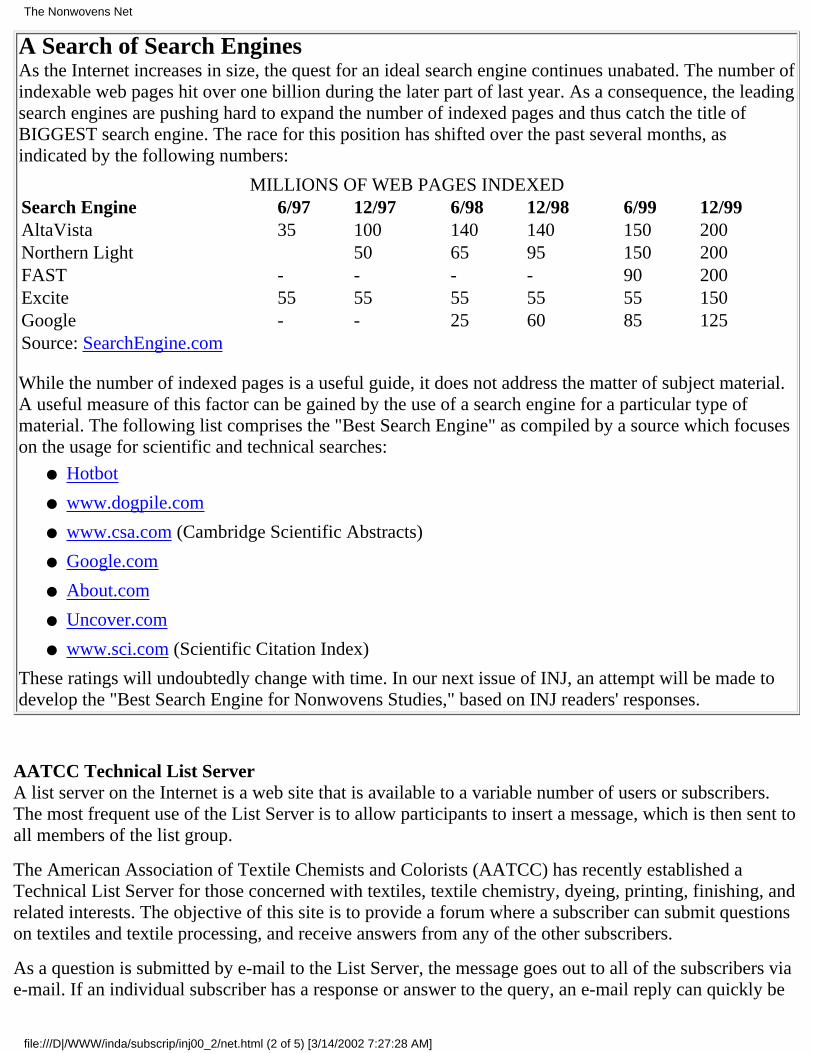
A Search of Search EnginesAs the Internet increases in size, the quest for an ideal search engine continues unabated. The number ofindexable web pages hit over one billion during the later part of last year. As a consequence, the leadingsearch engines are pushing hard to expand the number of indexed pages and thus catch the title ofBIGGEST search engine. The race for this position has shifted over the past several months, asindicated by the following numbers:
MILLIONS OF WEB PAGES INDEXEDSearch Engine 6/97 12/97 6/98 12/98 6/99 12/99AltaVista 35 100 140 140 150 200Northern Light 50 65 95 150 200FAST - - - - 90 200Excite 55 55 55 55 55 150Google - - 25 60 85 125Source: SearchEngine.com
While the number of indexed pages is a useful guide, it does not address the matter of subject material.A useful measure of this factor can be gained by the use of a search engine for a particular type ofmaterial. The following list comprises the "Best Search Engine" as compiled by a source which focuseson the usage for scientific and technical searches:
Hotbot●
www.dogpile.com●
www.csa.com (Cambridge Scientific Abstracts)●
Google.com●
About.com●
Uncover.com●
www.sci.com (Scientific Citation Index)●
These ratings will undoubtedly change with time. In our next issue of INJ, an attempt will be made todevelop the "Best Search Engine for Nonwovens Studies," based on INJ readers' responses.
AATCC Technical List ServerA list server on the Internet is a web site that is available to a variable number of users or subscribers.The most frequent use of the List Server is to allow participants to insert a message, which is then sent toall members of the list group.
The American Association of Textile Chemists and Colorists (AATCC) has recently established aTechnical List Server for those concerned with textiles, textile chemistry, dyeing, printing, finishing, andrelated interests. The objective of this site is to provide a forum where a subscriber can submit questionson textiles and textile processing, and receive answers from any of the other subscribers.
As a question is submitted by e-mail to the List Server, the message goes out to all of the subscribers viae-mail. If an individual subscriber has a response or answer to the query, an e-mail reply can quickly be
The Nonwovens Net
file:///D|/WWW/inda/subscrip/inj00_2/net.html (2 of 5) [3/14/2002 7:27:28 AM]
prepared and sent. If the subscriber has no response or interest to that particular inquiry, the e-mail isignored.
The AATCC Technical List Server currently has over 200 subscribers from over 28 countries. Asubscriber can leave the List at any time, and can rejoin as often as desired. For more information log onto http://www.aatcc.org .
Internet Source for Environmental,Health and Safety InformationA very helpful site providing information on environmental, health and safety (EHS) topics has beenestablished by ThermoRetec Corporation of Tucson, Arizona. This is a Gateway Site, which bypassesmuch of the tangled web of the Internet to sites specifically related to the EHS topic.
The site is organized by 11 key industries (chemical and pharmaceutical; financial; real estate andtransaction support; forest products; government nuclear facilities; industrial fuel users; manufacturingand consumer goods; medical facilities; mining; petroleum industry; transportation; utilities) andgovernment sectors (emergency response; environmental news sources; EPA; Federal EnvironmentalLegislation; other federal agencies; non-profit environmental groups; state and environmental agenciesand organizations; technical and engineering resources).
In addition, direct links to specific areas within the site are provided; most of the links are annotated tohelp in the choice of sites which best meet the specific need (www.ehsgateway.com).
e-Business GrowthJust as the number of Internet pages increase, there is much evidence that e-business - businessconducted on the Internet - is increasing also. B2B (business-to-business) as well as B2C(business-to-consumer) has shown explosive growth over the past months. A striking manifestation ofthis growth was provided by the situation at the recent Annual Conference and Exhibition of AORN(Association of Operating Room Nurses, now renamed as the Association of Perioperative Nurses). Justone year ago, there were three companies doing business in the segment, with Internet marketing tohospitals, clinics, nursing homes, physician offices, out-patient clinics and the like. In the recent AnnualConference there were 23 companies seeking this business on a national and international basis. It hardlyseems possible that the market can support this number; a shake-out of these participants seems morelikely.
There could easily be a new category of Internet business: B2R&D, as the number of businesses directedtoward the R&D activity and using the Internet increases.
SciQuest.com is a good example of this type of business, with e-marketing to the global scientificproducts industry. Their new website enables users to easily search through almost one million productsas well as consolidate purchases through an e-marketplace into single orders and to confirm and trackorders online. Additional features of this site include an enhanced resources section with easier access toonline journals. Scientific reference guides, conference calendars and other useful R&D sites areavailable at this location. The site also features live, online auctions, as well as the opportunity to lease,purchase or sell laboratory equipment. (SciQuest.com, P.O. Box 12156, Research Triangle Park, NC27709).
Another striking example of business-to-business auctions with special emphasis on scientific and
The Nonwovens Net
file:///D|/WWW/inda/subscrip/inj00_2/net.html (3 of 5) [3/14/2002 7:27:28 AM]

laboratory equipment is DoveBid (www.dovebid.com ). With 62 years of experience in conventionalauctions, Dove Brothers has made a strong pitch for this extension of their business.
Another interesting Internet business activity to scientists and technicians is the Internet exchange forscientific measurement services. This site (www.labseek.com ) is for users and suppliers of scientificmeasurements services. Companies that need scientific testing/expertise are given access to labs andscientists via the site's secure system. Any type of scientific measurement is matched with resources oflabs capable of constructing these tests, based on information in a proprietary member database. Thisdatabase has an inventory of each participant's available instrumentation, scientific expertise andmethods capabilities. The needs addressed by this service range from research and problem-solving tohighly defined analyses, to consulting on necessary test development and required resources. Primaryindustries served include chemical polymer, petroleum, food, pharmaceutical, agriculture, environmental,scientific products, clinical research and conformance testing. (LabSeek.com, 9608 Loiret Boulevard,Lenexa, KS 66219).
Further evidence of this trend is supplied by the various Internet companies exhibiting at the recentPittcon Conference on chemical and analytical technology. These included the following:
www.daigger.com : The site of A. Daigger & Co., lab suppliers.●
www.biosupplies.com : Supplier of biosupplies and chemicals for analysis.●
www.chemdex.com : Major chemical supplier on internet.●
www.ni.com : National Instruments, suppliers of laboratory instruments.●
www.comdisco.com : Laboratory equipment management specialists.●
www.atlims.com : Online laboratory information management systems supplier.●
www.auction.fishersci.com Surplus equipment site of Fisher Scientific.●
—INJ
Book Review
Spunbond/Meltblown Handbook
"The Spunbond and Meltblown Technology Handbook," Prepared for INDA by Ian Butler,International Nonwovens Consulting, Inc.; edited by Edward Vaughn, Ph.D., Clemson University andLarry Wadsworth, Ph.D., University of Tennessee; 50 pages.
Full of pictures, graphs and diagrams, this handbook does a great job of covering the basics of theseimportant and growing technologies. Also included are spunbond/meltblown composite fabrics as wellas an introduction to the major market applications and physical properties of each technology segment.Available from INDA at www.inda.org, major topics include:
Historical developments, including the major milestones and drivers for each technology.●
Worldwide and regional market growth.●
Physical properties of the important resin types.●
Principal end markets and specific market "success stories."●
Considerable market size information and a glossary complete the handbook, making it a handy
The Nonwovens Net
file:///D|/WWW/inda/subscrip/inj00_2/net.html (4 of 5) [3/14/2002 7:27:28 AM]

reference for a wide range of people involved in the field of nonwovens.
Return to International Nonwovens JournalHome Page & Table of Contents
The Nonwovens Net
file:///D|/WWW/inda/subscrip/inj00_2/net.html (5 of 5) [3/14/2002 7:27:28 AM]

INJ DEPARTMENTS
ASSOCIATION NEWSANSI Change of AddressANSI (The American National Standards Institute) is the official U.S. representative to the world's majorstandards bodies, which includes such organizations as ISO (International Organization forStandardization) and the IEC (International Electrotechnical Commission), plus several others. It is aprivate, non-profit organization that administers and coordinates the U.S. voluntary standardizationsystem.
ANSI recently announced the opening of its new headquarters in Washington, D.C. It had beenheadquartered in New York City since its founding in 1918.
In announcing the new office, it was indicated that "the decision to relocate ANSI Headquarters to thenation's capital will enable us to work even more closely with U.S. public policy leaders. Thisstrengthened link between the private and public sectors will greatly enhance the Institute's ability tofocus on domestic, regional and global issues in line with the Institute's mission."
The Institute's domestic and international standards facilitation programs, and its administrativeoperations, will remain in the New York City offices. The address for the new headquarters is TheAmerican National Standards Institute, 1819 L Street, NW, Sixth Floor, Washington, DC 20036;202-293-8020; Fax 202-293-9287
AAMI MembershipBecause of interest shown by numerous members, INDA has obtained official membership in AAMI, theAssociation for the Advancement of Medical Instrumentation. The driving force for INDA membershipin this association is the fact that AAMI has been a prime driver for advancement of materials andmethods for cutting-edge medical technology.
In addition, AAMI has a committee (PB 70) devoted to work on a standard for "Barrier Performance andClassification for Protective Apparel and Drapes in Healthcare Facilities." This committee is slated toassign class values for such products as well as descriptive terms relating the the performance of suchproducts. It is also planned that the committee will complement the eventual standards with test methodsand test results to be applied to each product class. The label requirements for such products will also bedeveloped. The FDA has indicated that it will likely adopt these standards as its own once the work iscompleted.
Association News
file:///D|/WWW/inda/subscrip/inj00_2/news.html (1 of 2) [3/14/2002 7:27:50 AM]

In addition to INDA, several individual INDA members are active in AAMI. Other participatingorganizations include AORN, FDA and the American College of Surgeons, as well as other groups andindependent healthcare experts. Active INDA participation will help insure that single-use gowns anddrapes remain competitive in this market.
—INJ
Return to International Nonwovens JournalHome Page & Table of Contents
Association News
file:///D|/WWW/inda/subscrip/inj00_2/news.html (2 of 2) [3/14/2002 7:27:50 AM]
INJ DEPARTMENTS
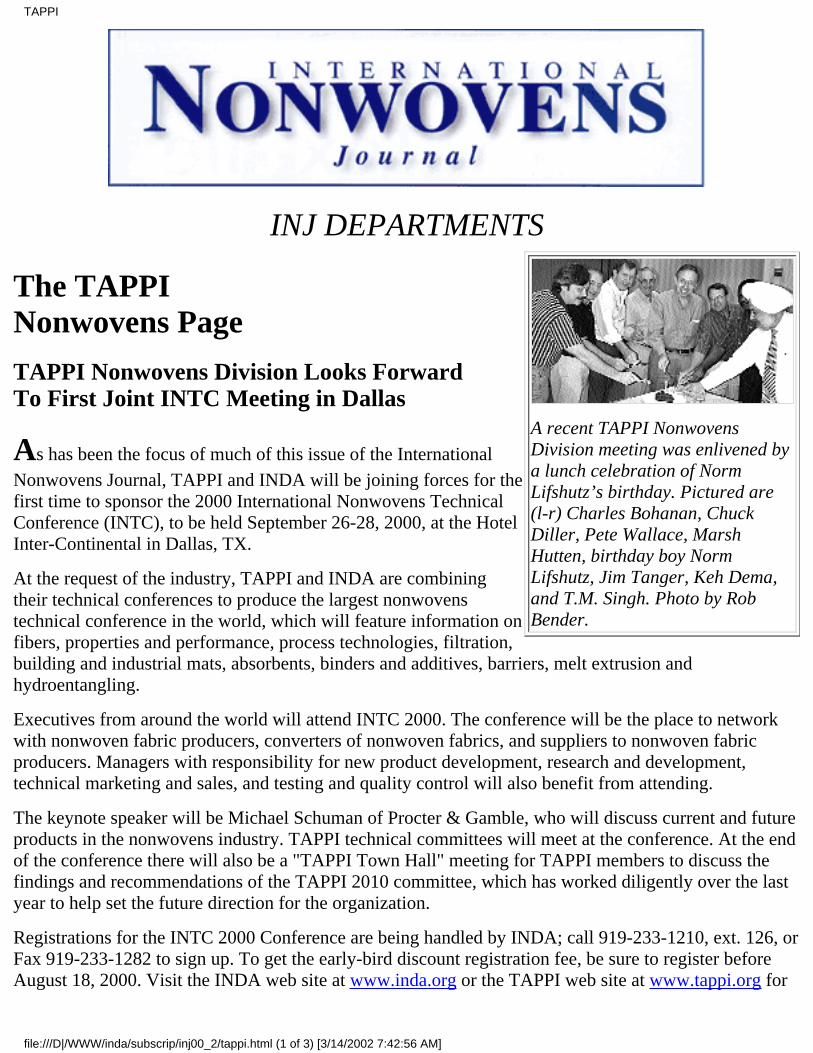
A recent TAPPI NonwovensDivision meeting was enlivened bya lunch celebration of NormLifshutz’s birthday. Pictured are(l-r) Charles Bohanan, ChuckDiller, Pete Wallace, MarshHutten, birthday boy NormLifshutz, Jim Tanger, Keh Dema,and T.M. Singh. Photo by RobBender.
The TAPPINonwovens Page
TAPPI Nonwovens Division Looks ForwardTo First Joint INTC Meeting in Dallas
As has been the focus of much of this issue of the InternationalNonwovens Journal, TAPPI and INDA will be joining forces for thefirst time to sponsor the 2000 International Nonwovens TechnicalConference (INTC), to be held September 26-28, 2000, at the HotelInter-Continental in Dallas, TX.
At the request of the industry, TAPPI and INDA are combiningtheir technical conferences to produce the largest nonwovenstechnical conference in the world, which will feature information onfibers, properties and performance, process technologies, filtration,building and industrial mats, absorbents, binders and additives, barriers, melt extrusion andhydroentangling.
Executives from around the world will attend INTC 2000. The conference will be the place to networkwith nonwoven fabric producers, converters of nonwoven fabrics, and suppliers to nonwoven fabricproducers. Managers with responsibility for new product development, research and development,technical marketing and sales, and testing and quality control will also benefit from attending.
The keynote speaker will be Michael Schuman of Procter & Gamble, who will discuss current and futureproducts in the nonwovens industry. TAPPI technical committees will meet at the conference. At the endof the conference there will also be a "TAPPI Town Hall" meeting for TAPPI members to discuss thefindings and recommendations of the TAPPI 2010 committee, which has worked diligently over the lastyear to help set the future direction for the organization.
Registrations for the INTC 2000 Conference are being handled by INDA; call 919-233-1210, ext. 126, orFax 919-233-1282 to sign up. To get the early-bird discount registration fee, be sure to register beforeAugust 18, 2000. Visit the INDA web site at www.inda.org or the TAPPI web site at www.tappi.org for
TAPPI
file:///D|/WWW/inda/subscrip/inj00_2/tappi.html (1 of 3) [3/14/2002 7:42:56 AM]
more details
Chairman's Corner
A Path ForwardBy T.M. Singh
We all know TAPPI has the privilege of a glorious past of approximately 85 years of service to thePulp and Paper and Allied Industries. The Nonwovens Division, though relatively newer, has its ownspecial place in the organization.
Over the past decade and a half, your Nonwovens Division has provided its members with impressivetechnical programs and conferences, well-attended trade shows, relevant professional tutorials, andshort courses on different aspects of nonwovens. Globalization of the industry, large-scale mergersand acquisitions, a revolution in communication technology, fierce economic competition, andfast-moving application technology, along with shorter life cycles of products, have had profoundeffect on how we have done business lately.
It seems imperative that we look at our current TAPPI structure and simplify it to make it moreeffective for future generations of technology leaders. TAPPI President Dick Barker has created the2010 Committee to examine current TAPPI structure and recommend how to respond to new businessrealities of today and tomorrow. You will learn more about TAPPI's action on 2010 Committeerecommendations and how TAPPI members can get the value they expect, and benefit by way ofparticipation in various activities in the near future.
As active Nonwovens Division members, some beneficial results include your participation in thejoint annual technical conference with INDA in September 2000 at Dallas (INTC 2000) andco-sponsoring this joint publication - the International Nonwovens Journal. The INJ has been wellreceived and I look forward to your participation in excellent technical programs at the InternationalNonwovens Technical Conference in September.
TAPPI administration and membership will continue to communicate using the full palette ofelectronic multi-media to ensure flow of information, highlighting how we plan to provide our corevalues and objectives, which have made us strong in the past, while we march on the path forward inthe New Millennium.
Return to International Nonwovens JournalHome Page & Table of Contents
TAPPI
file:///D|/WWW/inda/subscrip/inj00_2/tappi.html (2 of 3) [3/14/2002 7:42:56 AM]
INJ DEPARTMENTS
Where The Nonwovens Industry Comes To Learn
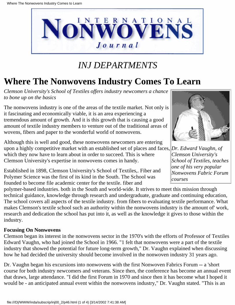
Dr. Edward Vaughn, ofClemson University'sSchool of Textiles, teachesone of his very popularNonwovens Fabric Forumcourses
Clemson University's School of Textiles offers industry newcomers a chanceto bone up on the basics
The nonwovens industry is one of the areas of the textile market. Not only isit fascinating and economically viable, it is an area experiencing atremendous amount of growth. And it is this growth that is causing a goodamount of textile industry members to venture out of the traditional areas ofwovens, fibers and paper to the wonderful world of nonwovens.
Although this is well and good, these nonwovens newcomers are enteringupon a highly competitive market with an established set of places and faces,which they now have to learn about in order to succeed. This is whereClemson University's expertise in nonwovens comes in handy.
Established in 1898, Clemson University's School of Textiles,. Fiber andPolymer Science was the first of its kind in the South. The School wasfounded to become file academic center for the textile. fiber andpolymer-based industries. both in the South and world-wide. It strives to meet this mission throughtechnical guidance, knowledge through research and undergraduate, graduate and continuing education,The school covers all aspects of the textile industry. from fibers to evaluating textile performance. Whatmakes Clemson's textile school such an authority within the nonwovens industry is the amount of' work,research and dedication the school has put into it, as well as the knowledge it gives to those within theindustry.
Focusing On NonwovensClemson began its interest in the nonwovens sector in the 1970's with the efforts of Professor of TextilesEdward Vaughn, who had joined the School in 1966. "1 felt that nonwovens were a part of the textileindustry that showed the potential for future long-term growth," Dr. Vaughn explained when discussinghow he had decided the university should become involved in the nonwoven industry 31 years ago.
Dr. Vaughn began his excursions into nonwovens with the first Nonwoven Fabrics Forum -- a 'shortcourse for both industry newcomers and veterans. Since then, the conference has become an annual eventthat draws, large attendance. "I did the first Forum in 1970 and since then it has become what I hoped itwould be - an anticipated annual event within the nonwovens industry," Dr. Vaughn stated. "This is an
Where The Nonwovens Industry Comes to Learn
file:///D|/WWW/inda/subscrip/inj00_2/p46.html (1 of 4) [3/14/2002 7:41:38 AM]
area where all the young, aggressive, intelligent and creative people are launching their careers. It hasbeen a joy for me, as I have made more new friendships than I can count."
According to Dr. Vaughn, over 2500 industry members have come throughthe four-day forum over the past 30 years, with some even coming backtwo or three times throughout the years. Each year since the early 70's themajority of speakers have been from the nonwovens industry itself andhave included many current chief executives, R&D directors, marketingand sales vice presidents, developers of numerous nonwoven products andinventors of new technologies. The forum also acts as an interactiveexperience by allowing ample time for attendees to informally meetspeakers, faculty and other members of' the nonwovens industry (for moreinformation on the Forum. see sidebar).
In addition to the Nonwoven Fabrics Forum, Clemson is also involved in nonwovens research through itson-site R&D facilities. "We have been involved in a lot of nonwovens research, which has been ongoingfor many years," Dr. Vaughn explained. "We have had quite a number of studies with students going fortheir degrees, governmental and proprietary research." The school has hosted work of a variety ofnonwoven processes. such as hydroentangling, needlepunching, meltblowing, spunbonding, resinbonding, thermal bonding and foam bonding. Some of' the equipment available at its nonwovenlaboratory includes web formation, processing and finishing equipment.
Meeting The Nonwovens FutureAs for the future direction of the school's involvement in nonwovens, Dr. Vaughn asserts that plans arebeing made to expand its commitment through program and faculty additions.
"For the past 30 years we have been really involved within all phases of the nonwovens business and wewill be expanding our efforts," he added. This expansion will reflect the growth of the nonwovensindustry as a whole, as more traditional textile members migrate into the nonwovens area and continue toneed a neutral place — such as the Nonwovens Fabrics Forum — to learn about the people, places andbasic ideas that define the nonwovens market.
"I hope the Forum will always be around because it creates the room to provided perspective on what hasbeen done with the industry before, which is something some people forget to look at that is important,"Dr Vaughn stated We bring in people from the industry to reach those interested in the industry on aneutral ground where they can learn objectively."
www.clemson.edu/success
Where The Nonwovens Industry Comes to Learn
file:///D|/WWW/inda/subscrip/inj00_2/p46.html (2 of 4) [3/14/2002 7:41:38 AM]

Nonwovens 101Approximately 140 nonwovens industry members were expected to venture to Clemson, SouthCarolina late this June for the 31st Annual Nonwovens Fabrics Forum at Clemson University. Inaddition to four days packed with basic nonwovens information, the Forum provides informalnetworking opportunities and the chance to ask questions and exchange ideas with other attendees.
Each year the Forum's program includes fundamental information on many areas of the nonwovensindustry, including manufacturers, raw materials, processes and technology presented from experiencedcolleagues from all areas of the industry.
On the first day, the Forum offers a basics course of the principles of woven, knitted and nonwovenfabrics, as well as a tour of Clemson's School of Textiles' nonwovens laboratory, where fiber processingand manufacturing, woven and nonwoven fabric manufacturing and product evaluation are examined.
On the following days, the program includes presentations on such topics as a history of nonwovens,fabric manufacturing basics, market and company profiles, fiber fundamentals, the future of theindustry, bonding, finishing and converting.
- INJ
BIBLIOGRAPHY DATABASENOW AVAILABLE
******************************
Search over 900 abstracts!!!INDA has added a new research tool to its website foryou. The Bibliography Database Search is designed tohelp you find papers that have been presented at INDAconferences. There are over 900 abstracts available inthe database and search criteria include PublicationYear, Conference Name and Key Words.
Where The Nonwovens Industry Comes to Learn
file:///D|/WWW/inda/subscrip/inj00_2/p46.html (3 of 4) [3/14/2002 7:41:38 AM]

Easy Access: Go to www.inda.org and click on theBibliography button.
**********************************If you have comments regarding our website, please contact Cindy Garcia ([email protected]),
INDA, Association of the Nonwoven Fabrics Industry, P.O. Box 1288, Cary, NC 27512-1288919-233-1210 ext 111; Fax: 919-233-1282; www.inda.org.
Return to International Nonwovens JournalHome Page & Table of Contents
Where The Nonwovens Industry Comes to Learn
file:///D|/WWW/inda/subscrip/inj00_2/p46.html (4 of 4) [3/14/2002 7:41:38 AM]
INJ DEPARTMENTS
NONWOVENS CALENDAR 2000-01August 2000
Aug. 20-24, 2000 220th American Chemical Society National Meeting. Washington DC, USA. ACSMeetings, 1155 16th St. N.W. Washington, DC 20036-4899; 202-872-4396; Fax: 202-872-6128;[email protected]
Aug. 27-31, 2000. TAPPI Polymers, Laminations & Coatings Conference. Westin Hotel, Chicago, IL,USA. TAPPI, Charles Bohanan; 770-209-7276; [email protected]
September 2000
Sep. 13-15, 2000. Bobbin Americas. Georgia World Congress Center, Atlanta, GA, USA. Blair Keever;972-906-6659; [email protected] or visit Bobbin Americas website at www.BobbinAmericas.com.
Sep. 19-21, 2000. INDA-Mexico 2000. World Trade Center, Mexico City, Mexico. Marilyn Bellinger,INDA, Association of the Nonwoven Fabrics Industry, P.O. Box 1288, Cary, NC 27512-1288;919-233-1210 ext. 118; [email protected]; www.inda.org.
Sep. 25-28, 2000. International Technical Nonwovens Conference - Co-sponsored by INDA andTAPPI. Hotel Inter-Continental, Dallas, TX, USA. Deanna Lovell, Education Coordinator, INDA,Association of the Nonwoven Fabrics Industry, P.O. Box 1288, Cary, NC 27512-1288; 919-233-1210ext. 119; Fax: 919-233-1282; [email protected] www.inda.org; or TAPPI, Charles Bohanan;770-209-7276; [email protected]
October 2000
Oct. 4-6, 2000. EDANA Absorbent Hygiene Products Training Course. Brussels, Belgium. ValérieSkupiewski, EDANA, 157 avenue Eugène Plasky, B-1030 Brussels, Belgium; Tel: +32-2-734-93-10;Fax: +32-2-733-35-18; [email protected]
Oct. 15-18, 2000. EuroGeo 2000. Bologna, Italy. Susanna Antonielli, Italian Geotechnical Society(AGI); Tel: +39-6-4424-9272; Fax: +39-06-4424-9274; [email protected]
Oct. 15-28, 2000. American Association of Textile Chemists and Colorists, InternationalConference and Exhibition. Benton Convention Center, Winston-Salem, NC, USA. AATCC, Research
NONWOVENS CALENDAR 2000-01
file:///D|/WWW/inda/subscrip/inj00_2/cal.html (1 of 2) [3/14/2002 7:24:27 AM]
Triangle Park, NC, USA; 919-549-8141; Fax: 919-549-8933; www.aatcc.org
Oct. 18-20, 2000. Tech Textil Asia. INTEX Osaka, Japan. Michael Jänecke/Silke Sakouchy, MesseFrankfurt, TechtextilTeam, Ludwig-Erhard-Anlage 1, D-60327 Frankfurt am Main;+49-69-7575-6415-6578-6406; Fax: +49-69-7575-6541; [email protected]
Oct. 23-27, 2000. ATME-I 2000 American Textile Machinery Exhibition-International 2000.Palmetto Expo Center, Greenville, SC, USA. J. Robert Ellis, ATME, P.O. Box 5823, Greenville, SC29606. 864-233-2562; Fax: 864-233-0619; [email protected]
Oct. 29-Nov. 3, 2000. American Chemical Society-Eastern Analytical Symposium. Atlantic City, NJ,USA. Eastern Analytical Symposium, P.O. Box 633, Montchanin, DE 19710-0633; 302-738-6218; Fax:302-738-5275; www.eas.org
November 2000
Nov. 8-10, 2000. The Tenth Annual International TANDEC Nonwovens Conference. The Universityof Tennessee Conference Center, Knoxville, TN, USA. Dr. Dong Zhang, Conference Chairman, Textiles& Nonwovens Development Center, 1321 White Avenue, University of Tennessee, Knoxville, TN37996; 865-974-3573; [email protected]; www.utk.edu/~tancon
Nov. 8-10, 2000. The Fiber Society, Fall 2000 Meeting. Callaway Gardens, Pine Mountain, GA, USA.Dr. Steve Michielsen and Dr. Mary Lynn Realf, Georgia Tech; 404-894-2430; Fax: 404-894-8780.
Nov. 12-14, 2000.. Annual Private Label Trade Show and Conference. Rosemont Convention Center,Chicago, IL, USA. PLMA, 369 Lexington Ave., New York, NY 10017; 212-972-3131; Fax:212-983-1382.
Nov.. 26-Dec. 1, 2000. The 10th International Wool Textile Research Conference. Aachen, Germany.Deutsches Wollforschungsinstitut, Veltmanplatz 8, D-52062 Aachen, Germany; ++49 (0)241/44-69-129; Fax: ++49(0)241/44-69-100; [email protected].
Nov. 28-30, 2000. Filtration 2000. Pennsylvania Convention Center, Philadelphia, PA, USA. INDA,Association of the Nonwoven Fabrics Industry, P.O. Box 1288, Cary, NC 27512-1288; 919-233-1210;Fax: 919-233-1282; www.inda.org
Nov. 29-30, 2000 . Aachen Textile Conference. Aachen, Germany. Deutsches Wollforschungsinstitut,Veltmanplatz 8, D-52062 Aachen, Germany; Tel: ++49 (0) 241/44-69-129; Fax: ++49 (0)241/44-69-100;E-mail: [email protected]. .
—INJ
Return to International Nonwovens JournalHome Page & Table of Contents
NONWOVENS CALENDAR 2000-01
file:///D|/WWW/inda/subscrip/inj00_2/cal.html (2 of 2) [3/14/2002 7:24:27 AM]
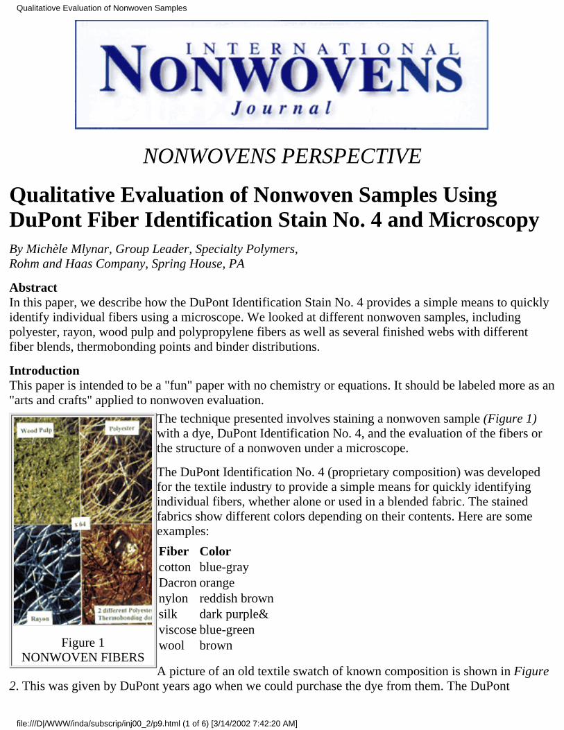
NONWOVENS PERSPECTIVE
Qualitative Evaluation of Nonwoven Samples UsingDuPont Fiber Identification Stain No. 4 and MicroscopyBy Michèle Mlynar, Group Leader, Specialty Polymers,Rohm and Haas Company, Spring House, PA
AbstractIn this paper, we describe how the DuPont Identification Stain No. 4 provides a simple means to quicklyidentify individual fibers using a microscope. We looked at different nonwoven samples, includingpolyester, rayon, wood pulp and polypropylene fibers as well as several finished webs with differentfiber blends, thermobonding points and binder distributions.
IntroductionThis paper is intended to be a "fun" paper with no chemistry or equations. It should be labeled more as an"arts and crafts" applied to nonwoven evaluation.
Figure 1NONWOVEN FIBERS
The technique presented involves staining a nonwoven sample (Figure 1)with a dye, DuPont Identification No. 4, and the evaluation of the fibers orthe structure of a nonwoven under a microscope.
The DuPont Identification No. 4 (proprietary composition) was developedfor the textile industry to provide a simple means for quickly identifyingindividual fibers, whether alone or used in a blended fabric. The stainedfabrics show different colors depending on their contents. Here are someexamples:
Fiber Colorcotton blue-grayDacron orangenylon reddish brownsilk dark purple&viscose blue-greenwool brown
A picture of an old textile swatch of known composition is shown in Figure2. This was given by DuPont years ago when we could purchase the dye from them. The DuPont
Qualitatiove Evaluation of Nonwoven Samples
file:///D|/WWW/inda/subscrip/inj00_2/p9.html (1 of 6) [3/14/2002 7:42:20 AM]
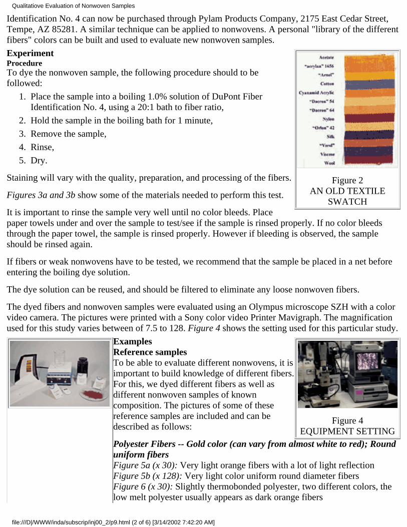
Identification No. 4 can now be purchased through Pylam Products Company, 2175 East Cedar Street,Tempe, AZ 85281. A similar technique can be applied to nonwovens. A personal "library of the differentfibers" colors can be built and used to evaluate new nonwoven samples.
Figure 2AN OLD TEXTILE
SWATCH
ExperimentProcedureTo dye the nonwoven sample, the following procedure should to befollowed:
Place the sample into a boiling 1.0% solution of DuPont FiberIdentification No. 4, using a 20:1 bath to fiber ratio,
1.
Hold the sample in the boiling bath for 1 minute,2.
Remove the sample,3.
Rinse,4.
Dry.5.
Staining will vary with the quality, preparation, and processing of the fibers.
Figures 3a and 3b show some of the materials needed to perform this test.
It is important to rinse the sample very well until no color bleeds. Placepaper towels under and over the sample to test/see if the sample is rinsed properly. If no color bleedsthrough the paper towel, the sample is rinsed properly. However if bleeding is observed, the sampleshould be rinsed again.
If fibers or weak nonwovens have to be tested, we recommend that the sample be placed in a net beforeentering the boiling dye solution.
The dye solution can be reused, and should be filtered to eliminate any loose nonwoven fibers.
The dyed fibers and nonwoven samples were evaluated using an Olympus microscope SZH with a colorvideo camera. The pictures were printed with a Sony color video Printer Mavigraph. The magnificationused for this study varies between of 7.5 to 128. Figure 4 shows the setting used for this particular study.
Figure 4EQUIPMENT SETTING
ExamplesReference samplesTo be able to evaluate different nonwovens, it isimportant to build knowledge of different fibers.For this, we dyed different fibers as well asdifferent nonwoven samples of knowncomposition. The pictures of some of thesereference samples are included and can bedescribed as follows:
Polyester Fibers -- Gold color (can vary from almost white to red); Rounduniform fibersFigure 5a (x 30): Very light orange fibers with a lot of light reflectionFigure 5b (x 128): Very light color uniform round diameter fibersFigure 6 (x 30): Slightly thermobonded polyester, two different colors, thelow melt polyester usually appears as dark orange fibers
Qualitatiove Evaluation of Nonwoven Samples
file:///D|/WWW/inda/subscrip/inj00_2/p9.html (2 of 6) [3/14/2002 7:42:20 AM]
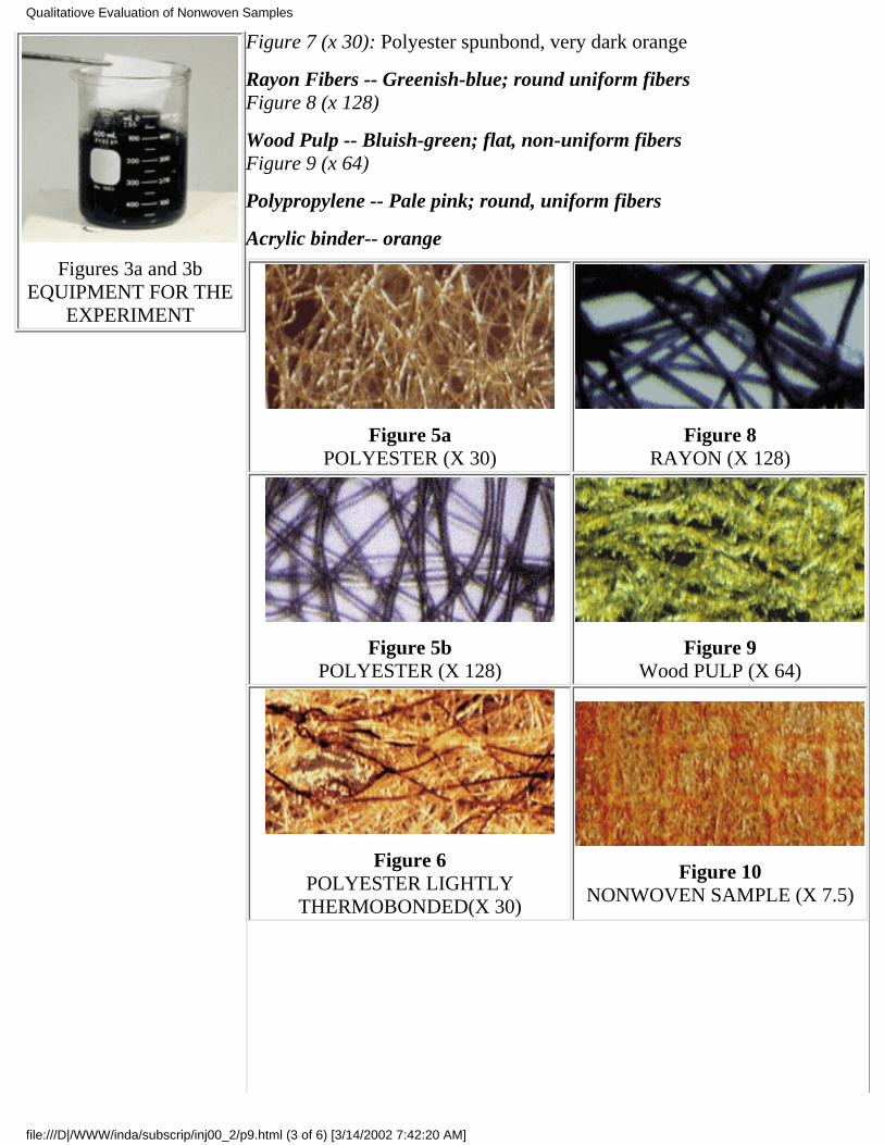
Figures 3a and 3bEQUIPMENT FOR THE
EXPERIMENT
Figure 7 (x 30): Polyester spunbond, very dark orange
Rayon Fibers -- Greenish-blue; round uniform fibersFigure 8 (x 128)
Wood Pulp -- Bluish-green; flat, non-uniform fibersFigure 9 (x 64)
Polypropylene -- Pale pink; round, uniform fibers
Acrylic binder-- orange
Figure 5aPOLYESTER (X 30)
Figure 8RAYON (X 128)
Figure 5bPOLYESTER (X 128)
Figure 9Wood PULP (X 64)
Figure 6POLYESTER LIGHTLY
THERMOBONDED(X 30)
Figure 10NONWOVEN SAMPLE (X 7.5)
Qualitatiove Evaluation of Nonwoven Samples
file:///D|/WWW/inda/subscrip/inj00_2/p9.html (3 of 6) [3/14/2002 7:42:20 AM]
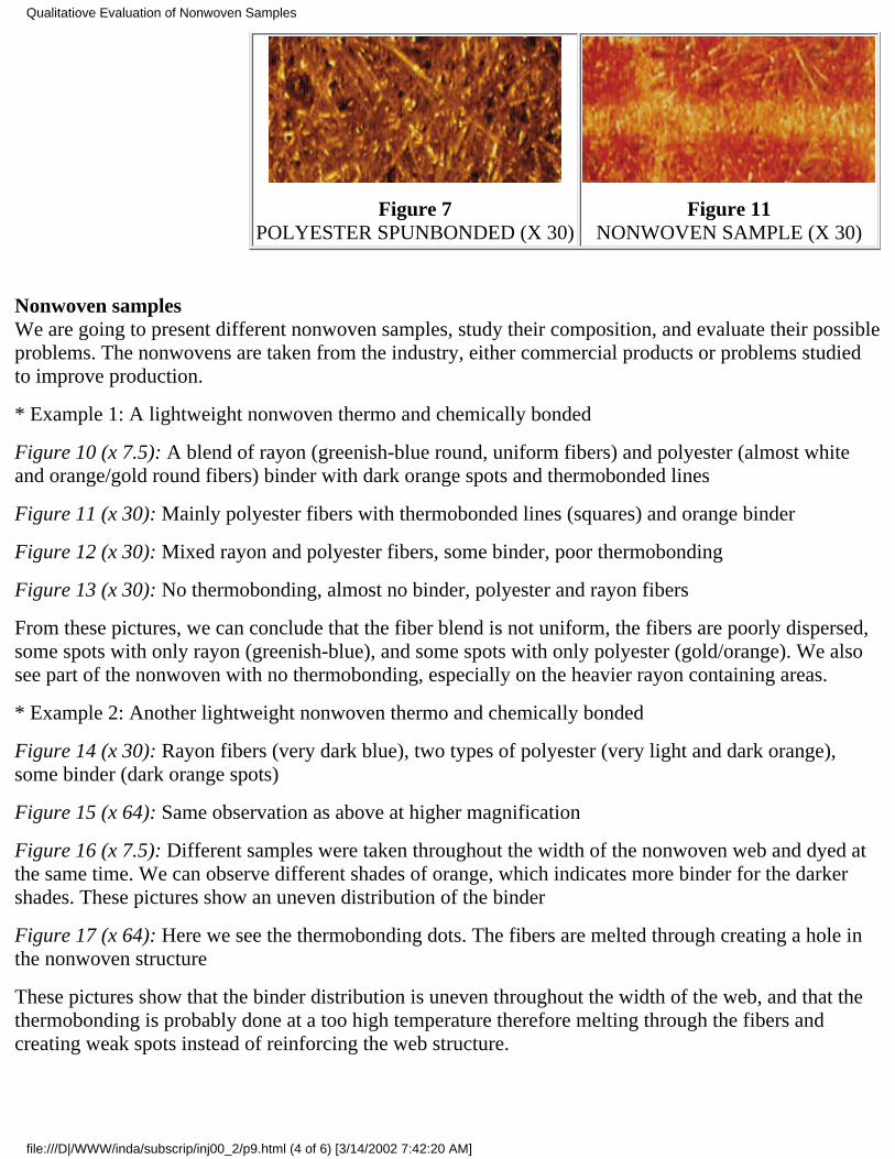
Figure 7POLYESTER SPUNBONDED (X 30)
Figure 11NONWOVEN SAMPLE (X 30)
Nonwoven samplesWe are going to present different nonwoven samples, study their composition, and evaluate their possibleproblems. The nonwovens are taken from the industry, either commercial products or problems studiedto improve production.
* Example 1: A lightweight nonwoven thermo and chemically bonded
Figure 10 (x 7.5): A blend of rayon (greenish-blue round, uniform fibers) and polyester (almost whiteand orange/gold round fibers) binder with dark orange spots and thermobonded lines
Figure 11 (x 30): Mainly polyester fibers with thermobonded lines (squares) and orange binder
Figure 12 (x 30): Mixed rayon and polyester fibers, some binder, poor thermobonding
Figure 13 (x 30): No thermobonding, almost no binder, polyester and rayon fibers
From these pictures, we can conclude that the fiber blend is not uniform, the fibers are poorly dispersed,some spots with only rayon (greenish-blue), and some spots with only polyester (gold/orange). We alsosee part of the nonwoven with no thermobonding, especially on the heavier rayon containing areas.
* Example 2: Another lightweight nonwoven thermo and chemically bonded
Figure 14 (x 30): Rayon fibers (very dark blue), two types of polyester (very light and dark orange),some binder (dark orange spots)
Figure 15 (x 64): Same observation as above at higher magnification
Figure 16 (x 7.5): Different samples were taken throughout the width of the nonwoven web and dyed atthe same time. We can observe different shades of orange, which indicates more binder for the darkershades. These pictures show an uneven distribution of the binder
Figure 17 (x 64): Here we see the thermobonding dots. The fibers are melted through creating a hole inthe nonwoven structure
These pictures show that the binder distribution is uneven throughout the width of the web, and that thethermobonding is probably done at a too high temperature therefore melting through the fibers andcreating weak spots instead of reinforcing the web structure.
Qualitatiove Evaluation of Nonwoven Samples
file:///D|/WWW/inda/subscrip/inj00_2/p9.html (4 of 6) [3/14/2002 7:42:20 AM]
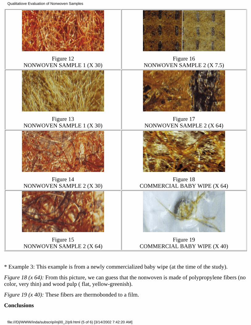
Figure 12NONWOVEN SAMPLE 1 (X 30)
Figure 16NONWOVEN SAMPLE 2 (X 7.5)
Figure 13NONWOVEN SAMPLE 1 (X 30)
Figure 17NONWOVEN SAMPLE 2 (X 64)
Figure 14NONWOVEN SAMPLE 2 (X 30)
Figure 18COMMERCIAL BABY WIPE (X 64)
Figure 15NONWOVEN SAMPLE 2 (X 64)
Figure 19COMMERCIAL BABY WIPE (X 40)
* Example 3: This example is from a newly commercialized baby wipe (at the time of the study).
Figure 18 (x 64): From this picture, we can guess that the nonwoven is made of polypropylene fibers (nocolor, very thin) and wood pulp ( flat, yellow-greenish).
Figure 19 (x 40): These fibers are thermobonded to a film.
Conclusions
Qualitatiove Evaluation of Nonwoven Samples
file:///D|/WWW/inda/subscrip/inj00_2/p9.html (5 of 6) [3/14/2002 7:42:20 AM]
This technique provides a relatively quick and inexpensive way to have a qualitative analysis of anonwoven sample, indicating the composition of the fibers as well as some production problemsencountered during the manufacturing of a nonwoven product.
AcknowledgementsThe author wants to thank Jeff Panara, who did all the photographic work on the pictures generated fromthe microscope camera.
--INJ
This paper was presented at the TAPPI Nonwovens 99 Conference (Orlando, Florida, March 15-17,1999). It was awarded the Best Paper.
- INJ
Return to International Nonwovens JournalHome Page & Table of Contents
Qualitatiove Evaluation of Nonwoven Samples
file:///D|/WWW/inda/subscrip/inj00_2/p9.html (6 of 6) [3/14/2002 7:42:20 AM]
ORIGINAL PAPER/Peer Reviewed
Cotton-Surfaced Nonwovens For Short-Wear-Cycle ApparelBy Larry C. Wadsworth, Hannah Suh, Textiles and Nonwovens Development Center, The University ofTennesseeKnoxville, Knoxville, TN, and H. Charles Allen. Jr., Cotton Incorporated, Raleigh, NC*
AbstractCotton-surfaced nonwovens have been developed with cotton on one side or both sides of a corestructure in which the cotton content varies from 41-75% of the fabric weight. The thermally bonded twoor three layered laminates are soft but strong and have a hand similar to cotton knits or hydroentangledfabrics. The fabrics have also demonstrated excellent wetting, wicking rates, water adsorption and waterretention properties. Although these novel fabrics have notable flexibility and extensibility as produced, apost-treatment process provides the fabrics with instantaneous elastic recoveries ranging from 83-93%from an extension of 50%. The fabrics exhibit minimal linting characteristics and would be suitable asmedical isolation gowns, head covers and shoe covers, bed sheets, pillow cases and for consumerapplications such as disposable underwear, towels, wipers and personal hygiene products.
BackgroundDisposable nonwovens entered the medical field over four decades ago, beginning with basic paper-likefacemasks and proceeding through sterilization wrap and specialty drapes and gowns to become close toa $2.5 billion market. These medical nonwovens have proven to be invaluable in products ranging fromdrape sheets to surgical gowns to adult pads and underpads by utilizing a gamut of nonwoven structures.The combining of nonwoven technologies has enabled the industry to offer products with propertieshitherto thought impossible.
The ease of tailoring nonwovens for specific end uses has facilitated great convenience in storage andidentification, leading to savings benefits in equipment, labor and inventory. Further savings are providedby the energy that may be recycled from incineration of the medical waste. Forecasting of needs has alsoimproved since it is simpler to monitor used products. [1]
Nonwovens now have almost complete acceptance in U.S. hospitals for applications such as surgicalcaps, masks and shoes covers and 90-100% penetration in operating room usage has resulted becausenonwoven provides relatively inexpensive, lightweight and effective protection. [2] Nonwovens havenow outpaced wovens in uses such as surgical gowns and drapes, wherein they have about 60-70% shareof the market. With the majority of the medical community being convinced that nonwoven disposablesgive double benefits of superior barrier protection and ease of use, it is only the psychological barrier thatneeds to be overcome before nonwovens achieve 80-90% penetration in the operating room market.
Cotton-Surfaced Nonwovens
file:///D|/WWW/inda/subscrip/inj00_2/p13.html (1 of 8) [3/15/2002 1:31:46 PM]
Now that cotton has successfully re-established itself as a major fiber in the conventional textile market,it is believed that the nonwoven field will also experience a resurgence of interest for it beyond theoriginal use of cotton linters and waste fibers in nonwovens. With the possible exception ofhydroentangled fabrics, which are produced by an energy extensive and relatively expensive process,nonwovens lack the strength, esthetics and comfort of woven and knitted fabrics. Cotton's probability forgrowth in nonwovens should be high because there are very few products making use of cotton and it hasa great potential in end use markets such as medical surgical products and sanitary products.
Cotton, by virtue of its unusual chemistry and structure, offers a set of properties including high tensilestrength, exceptional absorbency, high efficient wicking, natural resistance to electrostatic chargebuild-up, excellent heat resistance and good processability, all of which are important to the manufactureand performance of medical and health care products. Cotton is now economically available because ofinnovations being introduced by Cotton Incorporated and cotton suppliers, such as continuous scouringand bleaching processes. Suppliers have also improved the processability of cotton to meet the stringentrequirements of nonwoven manufacturers not just by increasing the openness of the fiber, but also byimproving types of finishes available, the application of finish and consistency of quality from lot to lot.This has made cotton extremely versatile in terms of processability and has made it possible to be used inmost of the nonwoven processes, with only processes requiring thermoplasticity such a melt extrusionbeing exceptions.
Preliminary research was performed at the Textiles and Nonwovens Development Center (TANDEC) atthe University of Tennessee to develop laminates containing bleached carded cotton cores without layersof meltblown (MB) webs (meltblown/cotton/meltblown or MCM laminates). The MB webs serve asbinder fiber materials during the subsequent thermal point bonding step and together with the cottonfibers impact both strength and barrier properties to the laminates. U.S. Patent No 5, 683,794 was issuedon November 4, 1997 to The University of Tennessee Research Corporation embodying concepts ofcotton core laminates employing a range of nonwoven out layers, with the inventors being L.C.Wadsworth, K.E. Duckett and V. Balasubramanian. The cotton core laminates were developed forapplications such as absorbent pads, towels and wipes, sanitary napkins, diapers and wound dressingsand, when treated with a repellent finish, may also be used for protective apparel such as surgical drapesand gowns.
In applications where greater strength is required, spunbond webs are used on one side in place of MBwebs to produce spunbond/cotton/meltblown (SCM) laminates. Although cotton serves efficiently as anabsorbent core, these laminates still lack aesthetics that could be attained if cotton was on the surface.However, research has found it is extremely difficult to produce thermally bonded laminates ofcotton/spunbond (CS) or cotton/spunbond/cotton (CSC) laminate, because the cotton fibers in unbondedor loosely bonded webs could not be efficiently transfer heat to the inner spunbond (SB) or meltblown(MB) webs, and instead the cotton fibers would wrap around the steel thermal calendar rolls. Anotherdrawback of the thermal bonded MCM, SCM, and SCS laminates was their lack of extensibility.However, it was demonstrated that they could be subsequently made elastic by subjecting them to acontrolled heating and stretching process invented by Hassenboehler and Wadsworth. [3-8]
Nevertheless, it was desirable to produce in one step a laminate with cotton on one or both surfaces,which also had a degree of extensibility. Thus, it was proposed by L.C. Wadsworth and H.C. Allen that itmay also be possible to achieve strength in laminates by laying webs containing loosely bonded cotton
Cotton-Surfaced Nonwovens
file:///D|/WWW/inda/subscrip/inj00_2/p13.html (2 of 8) [3/15/2002 1:31:46 PM]
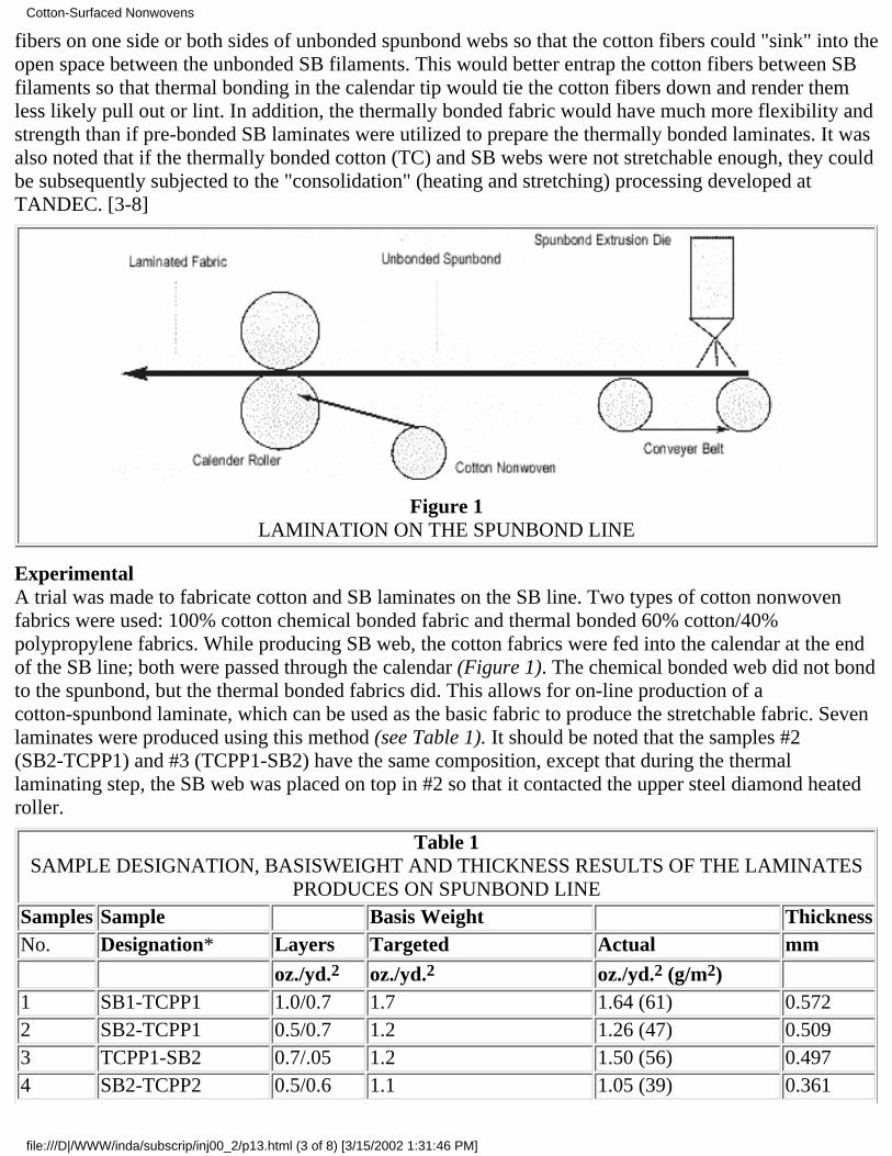
fibers on one side or both sides of unbonded spunbond webs so that the cotton fibers could "sink" into theopen space between the unbonded SB filaments. This would better entrap the cotton fibers between SBfilaments so that thermal bonding in the calendar tip would tie the cotton fibers down and render themless likely pull out or lint. In addition, the thermally bonded fabric would have much more flexibility andstrength than if pre-bonded SB laminates were utilized to prepare the thermally bonded laminates. It wasalso noted that if the thermally bonded cotton (TC) and SB webs were not stretchable enough, they couldbe subsequently subjected to the "consolidation" (heating and stretching) processing developed atTANDEC. [3-8]
Figure 1LAMINATION ON THE SPUNBOND LINE
ExperimentalA trial was made to fabricate cotton and SB laminates on the SB line. Two types of cotton nonwovenfabrics were used: 100% cotton chemical bonded fabric and thermal bonded 60% cotton/40%polypropylene fabrics. While producing SB web, the cotton fabrics were fed into the calendar at the endof the SB line; both were passed through the calendar (Figure 1). The chemical bonded web did not bondto the spunbond, but the thermal bonded fabrics did. This allows for on-line production of acotton-spunbond laminate, which can be used as the basic fabric to produce the stretchable fabric. Sevenlaminates were produced using this method (see Table 1). It should be noted that the samples #2(SB2-TCPP1) and #3 (TCPP1-SB2) have the same composition, except that during the thermallaminating step, the SB web was placed on top in #2 so that it contacted the upper steel diamond heatedroller.
Table 1SAMPLE DESIGNATION, BASISWEIGHT AND THICKNESS RESULTS OF THE LAMINATES
PRODUCES ON SPUNBOND LINESamples Sample Basis Weight ThicknessNo. Designation* Layers Targeted Actual mm oz./yd.2 oz./yd.2 oz./yd.2 (g/m2)
1 SB1-TCPP1 1.0/0.7 1.7 1.64 (61) 0.5722 SB2-TCPP1 0.5/0.7 1.2 1.26 (47) 0.5093 TCPP1-SB2 0.7/.05 1.2 1.50 (56) 0.4974 SB2-TCPP2 0.5/0.6 1.1 1.05 (39) 0.361
Cotton-Surfaced Nonwovens
file:///D|/WWW/inda/subscrip/inj00_2/p13.html (3 of 8) [3/15/2002 1:31:46 PM]
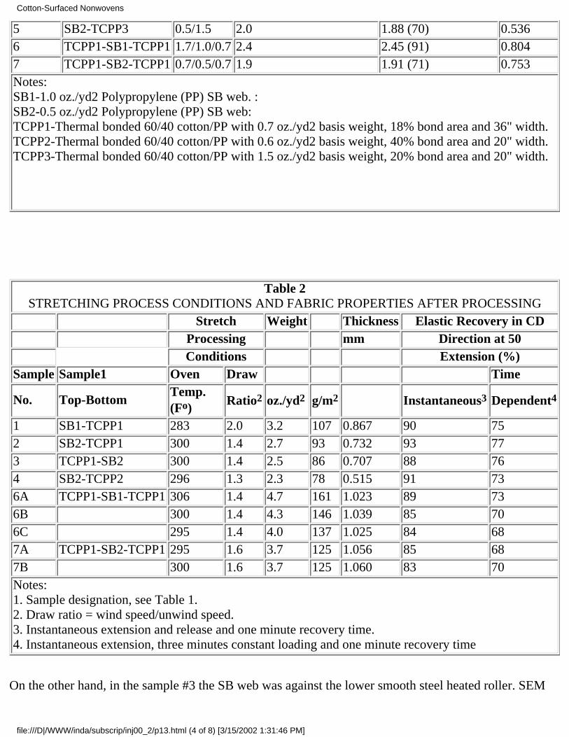
5 SB2-TCPP3 0.5/1.5 2.0 1.88 (70) 0.5366 TCPP1-SB1-TCPP1 1.7/1.0/0.7 2.4 2.45 (91) 0.8047 TCPP1-SB2-TCPP1 0.7/0.5/0.7 1.9 1.91 (71) 0.753Notes:SB1-1.0 oz./yd2 Polypropylene (PP) SB web. :SB2-0.5 oz./yd2 Polypropylene (PP) SB web:TCPP1-Thermal bonded 60/40 cotton/PP with 0.7 oz./yd2 basis weight, 18% bond area and 36" width.TCPP2-Thermal bonded 60/40 cotton/PP with 0.6 oz./yd2 basis weight, 40% bond area and 20" width.TCPP3-Thermal bonded 60/40 cotton/PP with 1.5 oz./yd2 basis weight, 20% bond area and 20" width.
Table 2STRETCHING PROCESS CONDITIONS AND FABRIC PROPERTIES AFTER PROCESSING
Stretch Weight Thickness Elastic Recovery in CD Processing mm Direction at 50 Conditions Extension (%)Sample Sample1 Oven Draw Time
No. Top-BottomTemp.(Fo) Ratio2 oz./yd2 g/m2 Instantaneous3 Dependent4
1 SB1-TCPP1 283 2.0 3.2 107 0.867 90 752 SB2-TCPP1 300 1.4 2.7 93 0.732 93 773 TCPP1-SB2 300 1.4 2.5 86 0.707 88 764 SB2-TCPP2 296 1.3 2.3 78 0.515 91 736A TCPP1-SB1-TCPP1 306 1.4 4.7 161 1.023 89 736B 300 1.4 4.3 146 1.039 85 706C 295 1.4 4.0 137 1.025 84 687A TCPP1-SB2-TCPP1 295 1.6 3.7 125 1.056 85 687B 300 1.6 3.7 125 1.060 83 70Notes:1. Sample designation, see Table 1.2. Draw ratio = wind speed/unwind speed.3. Instantaneous extension and release and one minute recovery time.4. Instantaneous extension, three minutes constant loading and one minute recovery time
On the other hand, in the sample #3 the SB web was against the lower smooth steel heated roller. SEM
Cotton-Surfaced Nonwovens
file:///D|/WWW/inda/subscrip/inj00_2/p13.html (4 of 8) [3/15/2002 1:31:46 PM]
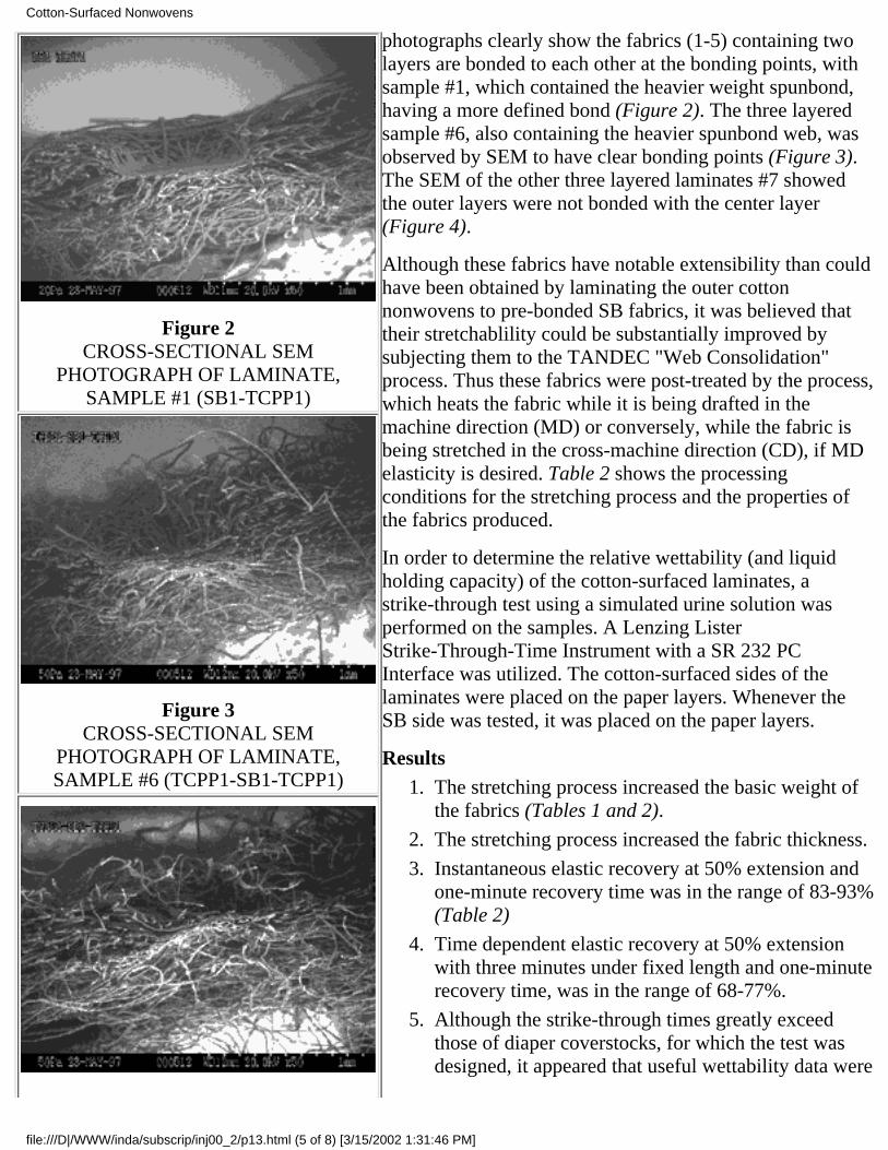
Figure 2CROSS-SECTIONAL SEM
PHOTOGRAPH OF LAMINATE,SAMPLE #1 (SB1-TCPP1)
Figure 3CROSS-SECTIONAL SEM
PHOTOGRAPH OF LAMINATE,SAMPLE #6 (TCPP1-SB1-TCPP1)
photographs clearly show the fabrics (1-5) containing twolayers are bonded to each other at the bonding points, withsample #1, which contained the heavier weight spunbond,having a more defined bond (Figure 2). The three layeredsample #6, also containing the heavier spunbond web, wasobserved by SEM to have clear bonding points (Figure 3).The SEM of the other three layered laminates #7 showedthe outer layers were not bonded with the center layer(Figure 4).
Although these fabrics have notable extensibility than couldhave been obtained by laminating the outer cottonnonwovens to pre-bonded SB fabrics, it was believed thattheir stretchablility could be substantially improved bysubjecting them to the TANDEC "Web Consolidation"process. Thus these fabrics were post-treated by the process,which heats the fabric while it is being drafted in themachine direction (MD) or conversely, while the fabric isbeing stretched in the cross-machine direction (CD), if MDelasticity is desired. Table 2 shows the processingconditions for the stretching process and the properties ofthe fabrics produced.
In order to determine the relative wettability (and liquidholding capacity) of the cotton-surfaced laminates, astrike-through test using a simulated urine solution wasperformed on the samples. A Lenzing ListerStrike-Through-Time Instrument with a SR 232 PCInterface was utilized. The cotton-surfaced sides of thelaminates were placed on the paper layers. Whenever theSB side was tested, it was placed on the paper layers.
ResultsThe stretching process increased the basic weight ofthe fabrics (Tables 1 and 2).
1.
The stretching process increased the fabric thickness.2.
Instantaneous elastic recovery at 50% extension andone-minute recovery time was in the range of 83-93%(Table 2)
3.
Time dependent elastic recovery at 50% extensionwith three minutes under fixed length and one-minuterecovery time, was in the range of 68-77%.
4.
Although the strike-through times greatly exceedthose of diaper coverstocks, for which the test wasdesigned, it appeared that useful wettability data were
5.
Cotton-Surfaced Nonwovens
file:///D|/WWW/inda/subscrip/inj00_2/p13.html (5 of 8) [3/15/2002 1:31:46 PM]
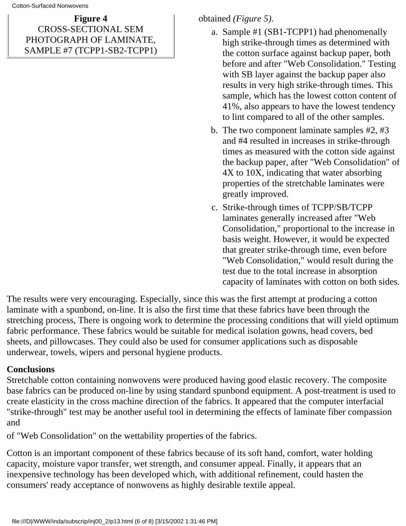
Figure 4CROSS-SECTIONAL SEM
PHOTOGRAPH OF LAMINATE,SAMPLE #7 (TCPP1-SB2-TCPP1)
obtained (Figure 5).
Sample #1 (SB1-TCPP1) had phenomenallyhigh strike-through times as determined withthe cotton surface against backup paper, bothbefore and after "Web Consolidation." Testingwith SB layer against the backup paper alsoresults in very high strike-through times. Thissample, which has the lowest cotton content of41%, also appears to have the lowest tendencyto lint compared to all of the other samples.
a.
The two component laminate samples #2, #3and #4 resulted in increases in strike-throughtimes as measured with the cotton side againstthe backup paper, after "Web Consolidation" of4X to 10X, indicating that water absorbingproperties of the stretchable laminates weregreatly improved.
b.
Strike-through times of TCPP/SB/TCPPlaminates generally increased after "WebConsolidation," proportional to the increase inbasis weight. However, it would be expectedthat greater strike-through time, even before"Web Consolidation," would result during thetest due to the total increase in absorptioncapacity of laminates with cotton on both sides.
c.
The results were very encouraging. Especially, since this was the first attempt at producing a cottonlaminate with a spunbond, on-line. It is also the first time that these fabrics have been through thestretching process, There is ongoing work to determine the processing conditions that will yield optimumfabric performance. These fabrics would be suitable for medical isolation gowns, head covers, bedsheets, and pillowcases. They could also be used for consumer applications such as disposableunderwear, towels, wipers and personal hygiene products.
ConclusionsStretchable cotton containing nonwovens were produced having good elastic recovery. The compositebase fabrics can be produced on-line by using standard spunbond equipment. A post-treatment is used tocreate elasticity in the cross machine direction of the fabrics. It appeared that the computer interfacial"strike-through" test may be another useful tool in determining the effects of laminate fiber compassionand
of "Web Consolidation" on the wettability properties of the fabrics.
Cotton is an important component of these fabrics because of its soft hand, comfort, water holdingcapacity, moisture vapor transfer, wet strength, and consumer appeal. Finally, it appears that aninexpensive technology has been developed which, with additional refinement, could hasten theconsumers' ready acceptance of nonwovens as highly desirable textile appeal.
Cotton-Surfaced Nonwovens
file:///D|/WWW/inda/subscrip/inj00_2/p13.html (6 of 8) [3/15/2002 1:31:46 PM]
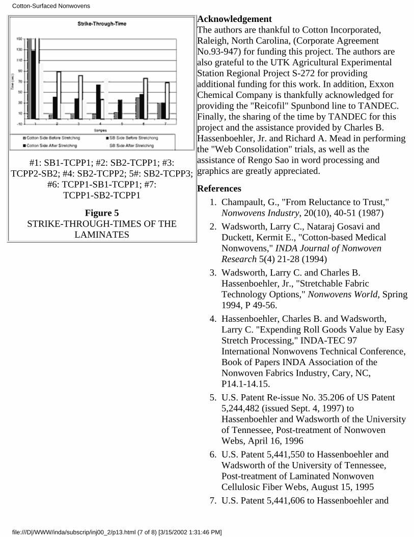
#1: SB1-TCPP1; #2: SB2-TCPP1; #3:TCPP2-SB2; #4: SB2-TCPP2; 5#: SB2-TCPP3;
#6: TCPP1-SB1-TCPP1; #7:TCPP1-SB2-TCPP1
Figure 5STRIKE-THROUGH-TIMES OF THE
LAMINATES
AcknowledgementThe authors are thankful to Cotton Incorporated,Raleigh, North Carolina, (Corporate AgreementNo.93-947) for funding this project. The authors arealso grateful to the UTK Agricultural ExperimentalStation Regional Project S-272 for providingadditional funding for this work. In addition, ExxonChemical Company is thankfully acknowledged forproviding the "Reicofil" Spunbond line to TANDEC.Finally, the sharing of the time by TANDEC for thisproject and the assistance provided by Charles B.Hassenboehler, Jr. and Richard A. Mead in performingthe "Web Consolidation" trials, as well as theassistance of Rengo Sao in word processing andgraphics are greatly appreciated.
ReferencesChampault, G., "From Reluctance to Trust,"Nonwovens Industry, 20(10), 40-51 (1987)
1.
Wadsworth, Larry C., Nataraj Gosavi andDuckett, Kermit E., "Cotton-based MedicalNonwovens," INDA Journal of NonwovenResearch 5(4) 21-28 (1994)
2.
Wadsworth, Larry C. and Charles B.Hassenboehler, Jr., "Stretchable FabricTechnology Options," Nonwovens World, Spring1994, P 49-56.
3.
Hassenboehler, Charles B. and Wadsworth,Larry C. "Expending Roll Goods Value by EasyStretch Processing," INDA-TEC 97International Nonwovens Technical Conference,Book of Papers INDA Association of theNonwoven Fabrics Industry, Cary, NC,P14.1-14.15.
4.
U.S. Patent Re-issue No. 35.206 of US Patent5,244,482 (issued Sept. 4, 1997) toHassenboehler and Wadsworth of the Universityof Tennessee, Post-treatment of NonwovenWebs, April 16, 1996
5.
U.S. Patent 5,441,550 to Hassenboehler andWadsworth of the University of Tennessee,Post-treatment of Laminated NonwovenCellulosic Fiber Webs, August 15, 1995
6.
U.S. Patent 5,441,606 to Hassenboehler and7.
Cotton-Surfaced Nonwovens
file:///D|/WWW/inda/subscrip/inj00_2/p13.html (7 of 8) [3/15/2002 1:31:46 PM]
Wadsworth of the University of Tennessee,Post-treatment of Nonwoven Webs, August 22,1995
U.S. Patent 5,599,366 to Hassenboehler andWadsworth of the University of Tennessee,Post-treatment of Nonwoven Webs, Feb. 4, 1997
8.
– INJ
* Now with INDA, Association of the Nonwoven Fabrics Industry
This paper was originally presented at the 1998 TAPPI Nonwoven Conference, St. Petersburg, FL,March 9-11, 1998
Return to International Nonwovens JournalHome Page & Table of Contents
Cotton-Surfaced Nonwovens
file:///D|/WWW/inda/subscrip/inj00_2/p13.html (8 of 8) [3/15/2002 1:31:46 PM]
ORIGINAL PAPER/Peer Reviewed
Pore Size andAir Permeability Of Four Nonwoven FabricsBy Helen H. Epps and Karen K. Leonas, The University of Georgia, Athens, GA
AbstractThe relationship between pore size and air permeability in two spunlaced fabrics and twospunbonded/meltblown/spunbonded (SMS) fabrics were investigated. Minimum, maximum and meanflow pore sizes were determined using liquid porosimetry. The influence of fabric weight and thicknesson air permeability and pore sizes was also evaluated. For the spunlaced fabrics, air permeability wasmost highly correlated with mean flow pore size, while there was a significant correlation between airpermeability and maximum pore size for the SMS fabrics. Liquid porosimetry is a useful technique inassessing pore sizes of nonwoven fabrics and can also aid in understanding the mechanism of airpermeability.
Key words: air permeability, liquid porosimetry, porosity, pore size, porometer, spunbonded, meltblown,spunlaced
IntroductionThermal insulation, filter media, and fluid barriers are among the nonwoven end-use applications that areinfluenced by the void volume within nonwoven materials. In most applications both the void volumeand its accessibility to the passage of air or other fluids are important. Although the terms "porosity" and"permeability" are sometimes used interchangeably, it is important to distinguish between the twoproperties. This paper presents a brief overview of research on relationships between structuralcharacteristics, porosity and air permeability of nonwovens, reviews some of the methods of poremeasurement and explores relationships between porosity and air permeability measurements of fournonwoven fabrics.
Air permeability is defined as "the rate of air flow through a material under a differential pressurebetween the two fabric surfaces." [1] Porosity can be defined as the total volume of void space containedwithin the boundaries of a material. In discussing the relationship between porosity and permeability,Scheidegger [2] prefers the term "pore structure," claiming that there can be no general correlationbetween porosity and permeability because the permeability of a material is influenced by the capillarypressure curves and the internal surface area of the pores within the material, rather than the actualvolume of the open space. Scheidegger maintains that even "pore size" is difficult to characterize
Pore Size and Air Permeability
file:///D|/WWW/inda/subscrip/inj00_2/p18.html (1 of 8) [3/14/2002 7:39:30 AM]
accurately because the pore system within a material typically forms a very complicated pore surface thatis geometrically irregular. The term "diameter" is typically used in describing pore size, but Scheideggernotes that this term is inappropriate because pores usually are not spherical, or even tube-shaped.
Calculated PorosityA theoretical, calculated value for porosity can be determined, and has been defined as the ratio of airspace to the total volume of the fabric, expressed as a percentage. [3] The terms used in this calculationare the specific gravity of the component fibers and the weight and thickness of the specimen, asindicated in the formula [4]:
P = 100 - Pa/Pb
where Pa is the fabric density and Pb is the fiber density. Fabric density, Pa, expressed in grams per cubic
centimeter (g/cc), is calculated by dividing the fabric weight (g/cm2) by the fabric thickness (cm):
Pa = (g/cm2)/cm.
Previous ResearchSeveral previous studies have addressed the relationship between air permeability and structuralcharacteristics of nonwovens, including fabric weight, thickness, density and fiber diameter. [5,6,7,8,9]Generally, these studies have shown that air permeability decreases nonlinearly as thickness, weight orfabric density increases. However, in a study of 80 nonwoven filters, air permeability declined linearlywith increases in thickness. The same study also showed that fabric density had a more significantinfluence on air permeability than either thickness or fiber size. [5]
In a study designed to determine how the method of conversion of a fiber web into a nonwoven fabricinfluenced air permeability, Kothari and Newton [6] found that among the needlepunched, stitchbondedand adhesive bonded fabrics that were evaluated, weight per unit area was a stronger determinant of airpermeability than either thickness or fabric density. Evaluating the same data, Dent [7] maintained thatthe second most important factor was fabric density.
Atwal [8] studied 140 needlepunched fabrics constructed from 16 different fibers. A wind tunnel wasused to determine fabric air resistance, the reciprocal of air permeability. Air resistance increased withfabric thickness and fabric weight per unit area, but decreased with fiber fineness.
Since nonwovens often are constructed from a blend of fibers, Subramaniam et al [9] investigated 48needlepunched fabrics composed of various proportions of different fibers, including jute, wool, acrylicand polypropylene. It was concluded that fiber volume fraction, defined as fabric density divided by fiberdensity, was an important factor in air permeability of these structures.
It has been said that there is no general correlation between air permeability and porosity [2] or betweenair permeability and liquid permeability. [10] The geometric configurations of any porous medium arecomplex and difficult to quantify. In the case of a nonrigid, flexible material, such as a nonwoven fabric,pore configurations can be even more complex and can change as the structure is deformed during themeasurement process. Although the irregularity of pore geometry complicates measurement, pore sizemeasurements of textile fabrics were reported as early as 1949. [11,12] Even earlier, Clayton [13]addressed the relationship between air permeability and porosity, identifying three factors in therelationship: 1) cross-sectional area of each pore; 2) depth of each pore, or the thickness of the fabric;
Pore Size and Air Permeability
file:///D|/WWW/inda/subscrip/inj00_2/p18.html (2 of 8) [3/14/2002 7:39:30 AM]
and 3) the number of pores per unit area.
The early research in fabric porosity relied almost exclusively on mercury intrusion. Mercuryporosimetry methods require measurement of mercury intrusion and extrusion under pressure in theevacuated specimen. [14] Developed in the field of petroleum technology, mercury intrusion/extrusionmethods have proven effective in measuring pores in rigid solids. However, mercury has a high surfacetension, requiring a high pressure to force it into pores. Consequently, when used in measuring flexiblematerials such as fabrics, the high pressure can distort the geometry of the pores that it attempts tocharacterize. [4,15] Using a lower pressure modification of the mercury intrusion technique, Burleigh etal [11] found a direct correlation between interfiber pore spaces and air permeability, and employing asimilar technique, Wakeham et al [12] found porosity data useful in explaining differences in airpermeability among a series of fabrics.
Miller and Tyomkin [15,16] developed a liquid extrusion method of pore analysis that can utilize anyliquid that completely wets the material. The specimen is saturated with the liquid, then the liquid isextruded as a pressure gradient is applied across the specimen and the extrusion is monitoredgravimetrically. Accurate in measuring pore diameters as small as 0.5 micrometers, the method measuresthe "effective radius" of pores, defined as the minimum distance between the surfaces within a pore,regardless of how irregularly shaped the pore is.
Miller and Tyomkin indicated that this method is particularly applicable for predicting liquid absorptionor retention by the material, but it may not be the best method to use in assessing barrier performancebecause it does not give a complete pore size distribution.
Although there has been only limited research on the relationship between porosity and air permeability,Hassenboehler [17] actually proposed the use of air permeability measurements over a range of pressuredrop in analyzing fabric pore structure. Previous work has demonstrated a nonlinear relationship betweenair permeability measurements and the pressure differential at which the test is performed. [18,19,20]This relationship was also noted in later research [21] and is addressed in a recent paper. [22] Buildingon this nonlinear relationship, Hassenboehler proposed that changes in the slope of the pressuredrop/permeability curve marked the onset of nonlinear air flow, or turbulence in the initial flow channels,and the addition of discrete air flow in separate, smaller channels. As the pressure differential isgradually increased, air flow is initiated through successively smaller pores.
The liquid extrusion method that forms the basis of ASTM method E 1294-89 [23] for porosimetry ofmembrane filters has been successfully used to evaluate porosity of textile materials, includingnonwovens. The specimen is wetted with a liquid of low surface tension and the liquid is extruded underincreasing air pressure. The maximum pore size is determined according to the first air flow, identified asthe bubble point. Air flow thorough the specimen increases as successively smaller pores empty, and theair flow is recorded as a function of air pressure. The results are compared with the flow rate through thedry sample and the data are used to determine pore size distribution for the sample. The liquid employedin the test may be the commercial product Porofil®, or isopropyl alcohol, water, or mineral oil. WhenPorofil® is used, the pore size measurement range of the porometer specified in the method is 0.05 to300 µM. Pore "size" represents pore diameter. Neither specimen thickness nor the complexity of the porestructure are considered in pore size measurement using the liquid extrusion method. However, a"tortuosity factor," defined as the reciprocal of porosity, may be specified in the test. The tortuosity factoris a rough indication of the complexity of the flow path, or the deviation from the theoretical cylindrical
Pore Size and Air Permeability
file:///D|/WWW/inda/subscrip/inj00_2/p18.html (3 of 8) [3/14/2002 7:39:30 AM]
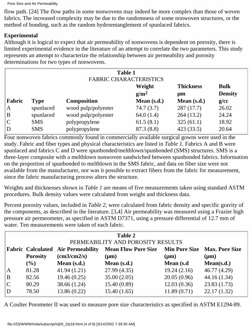
flow path. [24] The flow paths in some nonwovens may indeed be more complex than those of wovenfabrics. The increased complexity may be due to the randomness of some nonwoven structures, or themethod of bonding, such as the random hydroentanglement of spunlaced fabrics.
ExperimentalAlthough it is logical to expect that air permeability of nonwovens is dependent on porosity, there islimited experimental evidence in the literature of an attempt to correlate the two parameters. This studyrepresents an attempt to characterize the relationship between air permeability and porositydeterminations for two types of nonwovens.
Table 1FABRIC CHARACTERISTICS
Weight Thickness Bulk g/m2 µm DensityFabric Type Composition Mean (s.d.) Mean (s.d.) g/ccA spunlaced wood pulp/polyester 74.7 (3.7) 287 (17.7) 26.02B spunlaced wood pulp/polyester 64.0 (1.4) 264 (13.2) 24.24C SMS polypropylene 61.5 (8.1) 325 (61.1) 18.92D SMS polypropylene 87.3 (8.8) 423 (33.5) 20.64
Four nonwoven fabrics commonly found in commercially available surgical gowns were used in thestudy. Fabric and fiber types and physical characteristics are listed in Table 1. Fabrics A and B werespunlaced and fabrics C and D were spunbonded/meltblown/spunbonded (SMS) structures. SMS is athree-layer composite with a meltblown nonwoven sandwiched between spunbonded fabrics. Informationon the proportion of spunbonded to meltblown in the SMS fabric, and data on fiber size were notavailable from the manufacturer, nor was it possible to extract fibers from the fabric for measurement,since the fabric manufacturing process alters the structure.
Weights and thicknesses shown in Table 1 are means of five measurements taken using standard ASTMprocedures. Bulk density values were calculated from weight and thickness data.
Percent porosity values, included in Table 2, were calculated from fabric density and specific gravity ofthe components, as described in the literature. [3,4] Air permeability was measured using a Frazier highpressure air permeometer, as specified in ASTM D7371, using a pressure differential of 12.7 mm ofwater. Ten measurements were taken of each fabric.
Table 2PERMEABILITY AND POROSITY RESULTS
Fabric Calculated Air Permeability Mean Flow Pore Size Min Pore Size Max. Pore Size Porosity (cm3/cm2/s) (µm) (µm) (µm) (%) Mean (s.d.) Mean (s.d.) Mean (s.d Mean(s.d.)A 81.28 41.94 (1.21) 27.99 (4.35) 19.24 (2.16) 46.77 (4.29)B 82.56 19.46 (0.25) 35.00 (2.05) 20.05 (0.96) 44.16 (1.34)C 80.29 38.66 (1.24) 15.40 (0.89) 12.03 (0.36) 23.83 (1.73)D 78.50 13.86 (0.22) 15.40 (1.65) 11.89 (0.71) 22.17 (1.32)
A Coulter Porometer II was used to measure pore size characteristics as specified in ASTM E1294-89.
Pore Size and Air Permeability
file:///D|/WWW/inda/subscrip/inj00_2/p18.html (4 of 8) [3/14/2002 7:39:30 AM]
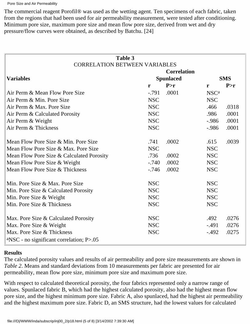
The commercial reagent Porofil® was used as the wetting agent. Ten specimens of each fabric, takenfrom the regions that had been used for air permeability measurement, were tested after conditioning.Minimum pore size, maximum pore size and mean flow pore size, derived from wet and drypressure/flow curves were obtained, as described by Batchu. [24]
Table 3CORRELATION BETWEEN VARIABLES
Correlation Variables Spunlaced SMS r P>r r P>rAir Perm & Mean Flow Pore Size -.791 .0001 NSCa Air Perm & Min. Pore Size NSC NSC Air Perm & Max. Pore Size NSC .466 .0318Air Perm & Calculated Porosity NSC .986 .0001Air Perm & Weight NSC -.986 .0001Air Perm & Thickness NSC -.986 .0001 Mean Flow Pore Size & Min. Pore Size .741 .0002 .615 .0039Mean Flow Pore Size & Max. Pore Size NSC NSC Mean Flow Pore Size & Calculated Porosity .736 .0002 NSC Mean Flow Pore Size & Weight -.740 .0002 NSC Mean Flow Pore Size & Thickness -.746 .0002 NSC Min. Pore Size & Max. Pore Size NSC NSC Min. Pore Size & Calculated Porosity NSC NSC Min. Pore Size & Weight NSC NSC Min. Pore Size & Thickness NSC NSC Max. Pore Size & Calculated Porosity NSC .492 .0276Max. Pore Size & Weight NSC -.491 .0276Max. Pore Size & Thickness NSC -.492 .0275aNSC - no significant correlation; P>.05
ResultsThe calculated porosity values and results of air permeability and pore size measurements are shown inTable 2. Means and standard deviations from 10 measurements per fabric are presented for airpermeability, mean flow pore size, minimum pore size and maximum pore size.
With respect to calculated theoretical porosity, the four fabrics represented only a narrow range ofvalues. Spunlaced fabric B, which had the highest calculated porosity, also had the highest mean flowpore size, and the highest minimum pore size. Fabric A, also spunlaced, had the highest air permeabilityand the highest maximum pore size. Fabric D, an SMS structure, had the lowest values for calculated
Pore Size and Air Permeability
file:///D|/WWW/inda/subscrip/inj00_2/p18.html (5 of 8) [3/14/2002 7:39:30 AM]
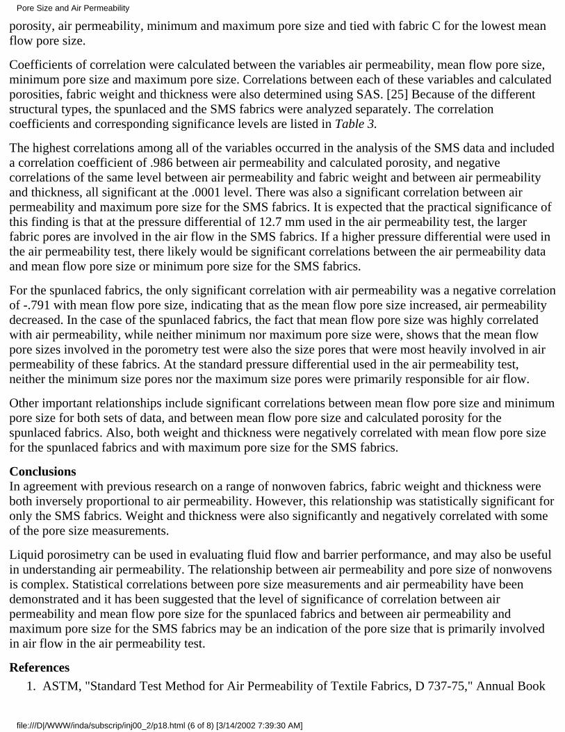
porosity, air permeability, minimum and maximum pore size and tied with fabric C for the lowest meanflow pore size.
Coefficients of correlation were calculated between the variables air permeability, mean flow pore size,minimum pore size and maximum pore size. Correlations between each of these variables and calculatedporosities, fabric weight and thickness were also determined using SAS. [25] Because of the differentstructural types, the spunlaced and the SMS fabrics were analyzed separately. The correlationcoefficients and corresponding significance levels are listed in Table 3.
The highest correlations among all of the variables occurred in the analysis of the SMS data and includeda correlation coefficient of .986 between air permeability and calculated porosity, and negativecorrelations of the same level between air permeability and fabric weight and between air permeabilityand thickness, all significant at the .0001 level. There was also a significant correlation between airpermeability and maximum pore size for the SMS fabrics. It is expected that the practical significance ofthis finding is that at the pressure differential of 12.7 mm used in the air permeability test, the largerfabric pores are involved in the air flow in the SMS fabrics. If a higher pressure differential were used inthe air permeability test, there likely would be significant correlations between the air permeability dataand mean flow pore size or minimum pore size for the SMS fabrics.
For the spunlaced fabrics, the only significant correlation with air permeability was a negative correlationof -.791 with mean flow pore size, indicating that as the mean flow pore size increased, air permeabilitydecreased. In the case of the spunlaced fabrics, the fact that mean flow pore size was highly correlatedwith air permeability, while neither minimum nor maximum pore size were, shows that the mean flowpore sizes involved in the porometry test were also the size pores that were most heavily involved in airpermeability of these fabrics. At the standard pressure differential used in the air permeability test,neither the minimum size pores nor the maximum size pores were primarily responsible for air flow.
Other important relationships include significant correlations between mean flow pore size and minimumpore size for both sets of data, and between mean flow pore size and calculated porosity for thespunlaced fabrics. Also, both weight and thickness were negatively correlated with mean flow pore sizefor the spunlaced fabrics and with maximum pore size for the SMS fabrics.
ConclusionsIn agreement with previous research on a range of nonwoven fabrics, fabric weight and thickness wereboth inversely proportional to air permeability. However, this relationship was statistically significant foronly the SMS fabrics. Weight and thickness were also significantly and negatively correlated with someof the pore size measurements.
Liquid porosimetry can be used in evaluating fluid flow and barrier performance, and may also be usefulin understanding air permeability. The relationship between air permeability and pore size of nonwovensis complex. Statistical correlations between pore size measurements and air permeability have beendemonstrated and it has been suggested that the level of significance of correlation between airpermeability and mean flow pore size for the spunlaced fabrics and between air permeability andmaximum pore size for the SMS fabrics may be an indication of the pore size that is primarily involvedin air flow in the air permeability test.
ReferencesASTM, "Standard Test Method for Air Permeability of Textile Fabrics, D 737-75," Annual Book1.
Pore Size and Air Permeability
file:///D|/WWW/inda/subscrip/inj00_2/p18.html (6 of 8) [3/14/2002 7:39:30 AM]
of ASTM Standards, (1995).
Scheidegger, A.L., "The Physics of Flow Through Porous Media," University of Toronto Press,Toronto (1974).
2.
Skinkle, J.H., "Textile Testing: Physical, Chemical and Microscopical," Chemical Publishing Co.,New York (1949), pp. 90-91.
3.
Hsieh, Y.L., "Liquid Transport in Fabric Structures," Textile Research Journal, 65 (5), 299-307(1995).
4.
Davis, N. C., "Factors Influencing the Air Permeability of Felt and Felt-Like Structures," TextileResearch Journal, 28 (4), 318-324 (1958).
5.
Kothari, V K. & A. Newton.. "The Air Permeability of Nonwoven Fabrics," Journal of the TextileInstitute, 65 (8), 525-531 (1974).
6.
Dent, R.W., "The Air Permeability of Nonwoven Fabrics," Journal of the Textile Institute, 46 (6),220-224 (1976).
7.
Atwal, M.S., "Factors Affecting the Air Resistance of Nonwoven Needlepunched Fabrics," TextileResearch Journal, 57 (10), 574-579 (1987).
8.
Subramaniam, V.; M. Madhusoothanan, & C.R. Debnath, "Air Permeability of BlendedNonwoven Fabrics," Textile Research Journal, 58 (11), 677-678 (1988).
9.
Scrivener, T.F., "The Differential-Pressure Air Permeability Test for Use in the Nonwovens, Filterand Paper Industries," TAPPI Journal, 76 (11), 221-224 (1993).
10.
Burleigh, E.G.; H. Wakeham; E. Honold, & E.L. Skau, "Pore Size Distribution in Textiles," TextileResearch Journal, 19 (9), 547-555 (1949).
11.
Wakeham, H. & N. Spicer, "Pore Size Distribution in Textiles - A Study of Windproof andWater-Resistant Cotton Fabrics," Textile Research Journal, 19 (11), 703-710 (1949).
12.
Clayton, F.H., "The Measurement of the Air Permeability of Fabrics," Journal of the TextileInstitute Transactions, 26T, 171-186 (1935).
13.
Moscou, L. & S. Lub. "Practical Use of Mercury Porosimetry in the Study of Porous Solids,"Powder Technology, 29 (1), 45-52 (1981).
14.
Miller, B. & I. Tyomkin, "An Extended Range Liquid Extrusion Method for Determining PoreSize Distributions," Textile Research Journal, 56 (1), 35-40 (1986).
15.
Miller, B. & I. Tyomkin, "Pore Size Distributions from Measurement of Liquid Uptake andRetention," Proceedings, 11th INDA Technical Symposium on Nonwovens Technology, 73-82(1983).
16.
Hassenboehler, C.B., "A New Method for Pore Structure Analysis Using Air Flow," TextileResearch Journal, 54 (4), 252-261 (1984).
17.
Hoerner, S.F., "Aerodynamic Properties of Screens Fabrics," Textile Research Journal, 22, (4),274-280 (1952).
18.
Goodings, A.C., "Air Flow Through Textile Fabrics," Textile Research Journal, 34 (8), 713-724(1964).
19.
Hassenboehler, C.B.; H.H. Epps, & B.C. Goswami, "A Method to Assess the Air Permeability ofOpen Textile Structures," paper presented at the Fiber Society Symposium on Fabric Formationand Analysis, Raleigh, NC, October 1982.
20.
Pore Size and Air Permeability
file:///D|/WWW/inda/subscrip/inj00_2/p18.html (7 of 8) [3/14/2002 7:39:30 AM]
Wehner, J.A.; B. Miller, & L. Rebenfeld, "Moisture Induced Changes in Fabric Structure asEvidenced by Air Permeability Measurements," Textile Research Journal, 57 (5), 247-256 (1987).
21.
Epps, H.H., "Prediction of Single Layer Fabric Air Permeability by Statistical Modeling," Journalof Testing and Evaluation, 24 (1), 26-31 (1996).
22.
ASTM, "Standard Test Method for Pore Size Characteristics of Membrane Filters UsingAutomated Liquid Porosimeter, E 1294-89," Annual Book of ASTM Standards, (1995).
23.
Batchu, H.R., "Characterization of Nonwovens for Pore Size Distributions Using AutomatedLiquid Porosimeter," TAPPI Proceedings, Nonwovens Conference, 367-381 (1990).
24.
SAS Institute Inc., SAS/STAT User's Guide, 1989, Version 6 (4th ed.), Cary, NC.25.
— INJ
Return to International Nonwovens JournalHome Page & Table of Contents
Pore Size and Air Permeability
file:///D|/WWW/inda/subscrip/inj00_2/p18.html (8 of 8) [3/14/2002 7:39:30 AM]
ORIGINAL PAPER/PEER-REVIEWED
Analysis of RoofingMat StructureBy Randall R. Bresee, Hong Yin and Zanyao YanTextiles and Nonwovens Development Center,The University of Tennessee, Knoxville, TN
AbstractWe describe hardware and software features of an image analysis-based instrument developed in ourlaboratory to characterize web structure. The potential value of detailed web analysis that is possibletoday using image analysis is illustrated for a small number of roofing mat webs by characterizing basisweight (small area) uniformity, fiber bundle orientation (directionality control) and fiber bundle diameter(dispersion quality). From this analysis, we show that it is possible to observe differences in webstructure between the top and wire sides of webs, built-up roofing and shingle mat webs, production withhydraulic pressurized (closed) and atmospheric (open) headboxes, production with and without a flowsynchronizer, and web basis weight.
IntroductionProperties of nonwoven webs, like the properties of any fibrous material, result from two general things -the properties of fibers in the web and the way fibers are assembled in the web (web structure). In otherwords, knowledge of web structure is necessary to understand web properties. It is also necessary to haveknowledge of the variation in web structure to understand some web properties (e.g., strength). It is alsogenerally desirable to measure web structure when evaluating changes in web production processes.
Detailed structural information is not usually obtained for nonwoven webs and variations in webstructure are measured even less often. An important reason for this is that analytical tools used tocharacterize web structure are generally lacking. However, remarkable advancements have occurredduring the last decade in technological areas that support the broad area of analysis. These includepersonal computers, video cameras and motion control devices. These advances have lead to thedevelopment of computer vision systems for analysis in diverse areas such as advertising and weaponsapplications. The successes of these applications suggest that vision techniques may be used tocharacterize web structure in the off-line laboratory environment as well as the on-line productionenvironment.
Advances seen during the last decade in desktop computer and imaging hardware are expected to
Analysis of Roofing Mat Structure
file:///D|/WWW/inda/subscrip/inj00_2/p23.html (1 of 13) [3/14/2002 7:40:10 AM]
continue in the future. It is reasonable to expect that computer-based vision systems will continue tobecome less expensive, more widely available, more familiar, more powerful and easier to operate.Similarly, computer software intended for widespread use (e.g., computer operating systems) willcontinue to become more sophisticated, more powerful and easier to operate. On the other hand,application-specific software that does not enjoy widespread public use must be developed by workers inthe application field. Ten years ago, we began to develop software specifically to characterize structurein nonwoven webs. This work has resulted in a good foundation of basic software techniques useful forweb structural characterization.
Nonwoven web analysis is more difficult than analysis of many materials. Web structural patterns are notreproducible as they are in many vision applications such as inspecting labels on food boxes. Nonwovenwebs also are relatively nonplanar. That is, analysis of many web features (e.g., single fiber diameter)requires a large enough magnification during image acquisition that the web is thick andthree-dimensional compared to the depth-of-field provided by the lens. Analysis of nonwoven webs isalso complicated by the fact that they often exhibit poor structural uniformity. For example, basis weightmay vary substantially in the MD (machine direction) and CD (cross direction) so web areas must beanalyzed from many locations along the MD and CD to obtain reliable and objective structuralinformation. Analysis is even more demanding for web defects since a large web area must be examinedwith no missed area and no overlap. These difficulties lead us to conclude that manually preparingenough samples representing an adequate web area and manually repositioning each sample betweenmeasurements is simply impractical and often accompanied by mistakes. From a practical standpoint,automating the analysis process should be an important functional element of a web analysis instrument.
Our laboratory has designed and developed a fully computer-controlled multifunction instrumentdedicated to nonwoven web analysis using image analysis-based techniques [1]. Manual analytical toolslimit analysis time, but automated systems encourage users to sample webs extensively enough to obtaingood analysis results. For example, manually measuring the fiber orientation distribution in only a smallarea of an individual web often requires an entire day. Automated image analysis-based measurementscan measure the orientation directions of several thousand fibers and plot the full orientation distributionin a few minutes.
The instrument we developed features powerful multifunction capability, flexible control and automatedsampling. It has proven to be efficient, convenient and flexible for analyzing nonwoven web structure.We can place a fairly large web sample (up to 50cm x 50cm or 15cm x 91cm) on the instrument, inputsettings for a test (total number of images to be acquired, web locations of acquired images, etc.) andthen start the program. Once analysis begins, it continues without human intervention until analysis iscompleted and then a statistical summary of analysis results and a data chart are ready to print. In view ofthe wealth of structural information available in images, a single image analysis-based instrument has thepotential to replace several other instruments used to characterize web structure. This makes theinstrument economical because several analysis modules share hardware and software resources.
We briefly discuss hardware and software features of the instrument developed in our laboratory andthen present analysis results for roofing mat samples obtained from different manufacturers usingvariations on the wetlay nonwovens process [2]. In particular, the samples were produced using differentheadbox systems. The number of available samples and our knowledge of roofing mat production wereboth quite limited, so our data cannot be used to reach definitive conclusions about web manufacture.However, we illustrate the potential value of web analysis that is available today by examining possible
Analysis of Roofing Mat Structure
file:///D|/WWW/inda/subscrip/inj00_2/p23.html (2 of 13) [3/14/2002 7:40:10 AM]
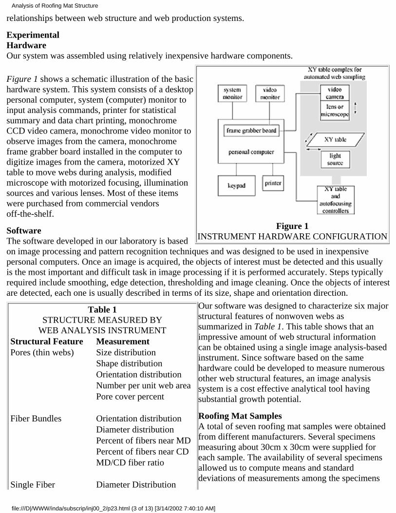
relationships between web structure and web production systems.
ExperimentalHardwareOur system was assembled using relatively inexpensive hardware components.
Figure 1INSTRUMENT HARDWARE CONFIGURATION
Figure 1 shows a schematic illustration of the basichardware system. This system consists of a desktoppersonal computer, system (computer) monitor toinput analysis commands, printer for statisticalsummary and data chart printing, monochromeCCD video camera, monochrome video monitor toobserve images from the camera, monochromeframe grabber board installed in the computer todigitize images from the camera, motorized XYtable to move webs during analysis, modifiedmicroscope with motorized focusing, illuminationsources and various lenses. Most of these itemswere purchased from commercial vendorsoff-the-shelf.
SoftwareThe software developed in our laboratory is basedon image processing and pattern recognition techniques and was designed to be used in inexpensivepersonal computers. Once an image is acquired, the objects of interest must be detected and this usuallyis the most important and difficult task in image processing if it is performed accurately. Steps typicallyrequired include smoothing, edge detection, thresholding and image cleaning. Once the objects of interestare detected, each one is usually described in terms of its size, shape and orientation direction.
Table 1STRUCTURE MEASURED BY
WEB ANALYSIS INSTRUMENTStructural Feature MeasurementPores (thin webs) Size distribution Shape distribution Orientation distribution Number per unit web area Pore cover percent Fiber Bundles Orientation distribution Diameter distribution Percent of fibers near MD Percent of fibers near CD MD/CD fiber ratio Single Fiber Diameter Distribution
Our software was designed to characterize six majorstructural features of nonwoven webs assummarized in Table 1. This table shows that animpressive amount of web structural informationcan be obtained using a single image analysis-basedinstrument. Since software based on the samehardware could be developed to measure numerousother web structural features, an image analysissystem is a cost effective analytical tool havingsubstantial growth potential.
Roofing Mat SamplesA total of seven roofing mat samples were obtainedfrom different manufacturers. Several specimensmeasuring about 30cm x 30cm were supplied foreach sample. The availability of several specimensallowed us to compute means and standarddeviations of measurements among the specimens
Analysis of Roofing Mat Structure
file:///D|/WWW/inda/subscrip/inj00_2/p23.html (3 of 13) [3/14/2002 7:40:10 AM]
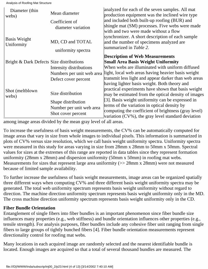
Diameter (thinwebs)
Mean diameter
Coefficient of diameter variation Basis WeightUniformity
MD, CD and TOTAL
uniformity spectra Bright & Dark Defects Size distributions Intensity distributions Numbers per unit web area Defect cover percent Shot (meltblownwebs)
Size distribution
Shape distribution Number per unit web area Shot cover percent
analyzed for each of the seven samples. All matproduction equipment was the inclined wire typeand included both built-up roofing (BUR) andshingle mat (SM) processes. Five webs were madewith and two were made without a flowsynchronizer. A short description of each sampleand the number of specimens analyzed aresummarized in Table 2.
Description of Web MeasurementsSmall Area Basis Weight UniformityWhen webs are illuminated with uniform diffusedlight, local web areas having heavier basis weighttransmit less light and appear darker than web areashaving lighter basis weight. Both theory andpractical experiments have shown that basis weightmay be estimated from the optical density of images[3]. Basis weight uniformity can be expressed interms of the variation in optical density bycomputing the coefficient of brightness (gray level)variation (CV%), the gray level standard deviation
among image areas divided by the mean gray level of all areas.
To increase the usefulness of basis weight measurements, the CV% can be automatically computed forimage areas that vary in size from whole images to individual pixels. This information is summarized inplots of CV% versus size resolution, which we call basis weight uniformity spectra. Uniformity spectrawere measured in this study for areas varying in size from 28mm x 28mm to 50mm x 50mm. Spectralvalues for sizes at the extremes of this range are reported in data tables since they represent formationuniformity (28mm x 28mm) and dispersion uniformity (50mm x 50mm) in roofing mat webs.Measurements for sizes that represent large area uniformity (>> 28mm x 28mm) were not measuredbecause of limited sample availability.
To further increase the usefulness of basis weight measurements, image areas can be organized spatiallythree different ways when computing CV% and three different basis weight uniformity spectra may begenerated. The total web uniformity spectrum represents basis weight uniformity without regard todirection. The machine direction uniformity spectrum represents basis weight uniformity only in the MD.The cross machine direction uniformity spectrum represents basis weight uniformity only in the CD.
Fiber Bundle OrientationEntanglement of single fibers into fiber bundles is an important phenomenon since fiber bundle sizeinfluences many properties (e.g., web stiffness) and bundle orientation influences other properties (e.g.,tensile strength). For analysis purposes, fiber bundles include any cohesive fiber unit ranging from singlefibers to large groups of tightly bunched fibers [4]. Fiber bundle orientation measurements representdirectionality control for roofing mat webs.
Many locations in each acquired image are randomly selected and the nearest identifiable bundle islocated. Enough images are acquired so that a total of several thousand bundles are measured. The
Analysis of Roofing Mat Structure
file:///D|/WWW/inda/subscrip/inj00_2/p23.html (4 of 13) [3/14/2002 7:40:10 AM]
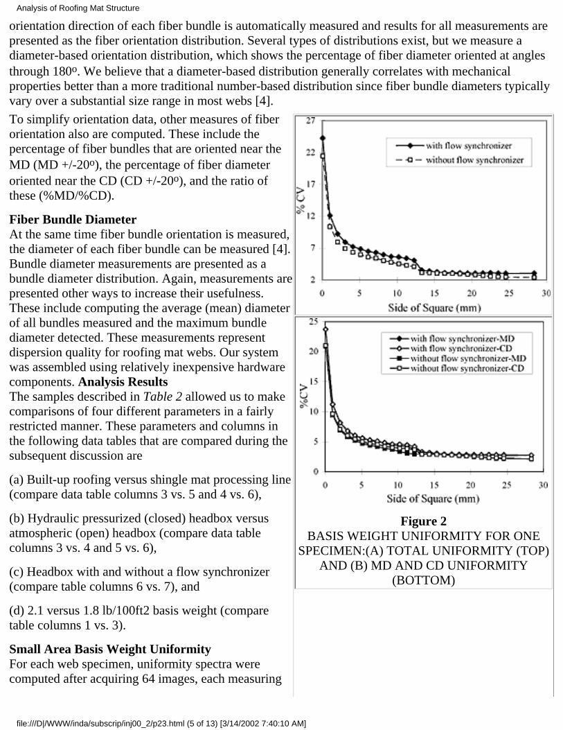
orientation direction of each fiber bundle is automatically measured and results for all measurements arepresented as the fiber orientation distribution. Several types of distributions exist, but we measure adiameter-based orientation distribution, which shows the percentage of fiber diameter oriented at anglesthrough 180o. We believe that a diameter-based distribution generally correlates with mechanicalproperties better than a more traditional number-based distribution since fiber bundle diameters typicallyvary over a substantial size range in most webs [4].
Figure 2BASIS WEIGHT UNIFORMITY FOR ONE
SPECIMEN:(A) TOTAL UNIFORMITY (TOP)AND (B) MD AND CD UNIFORMITY
(BOTTOM)
To simplify orientation data, other measures of fiberorientation also are computed. These include thepercentage of fiber bundles that are oriented near theMD (MD +/-20o), the percentage of fiber diameteroriented near the CD (CD +/-20o), and the ratio ofthese (%MD/%CD).
Fiber Bundle DiameterAt the same time fiber bundle orientation is measured,the diameter of each fiber bundle can be measured [4].Bundle diameter measurements are presented as abundle diameter distribution. Again, measurements arepresented other ways to increase their usefulness.These include computing the average (mean) diameterof all bundles measured and the maximum bundlediameter detected. These measurements representdispersion quality for roofing mat webs. Our systemwas assembled using relatively inexpensive hardwarecomponents. Analysis ResultsThe samples described in Table 2 allowed us to makecomparisons of four different parameters in a fairlyrestricted manner. These parameters and columns inthe following data tables that are compared during thesubsequent discussion are
(a) Built-up roofing versus shingle mat processing line(compare data table columns 3 vs. 5 and 4 vs. 6),
(b) Hydraulic pressurized (closed) headbox versusatmospheric (open) headbox (compare data tablecolumns 3 vs. 4 and 5 vs. 6),
(c) Headbox with and without a flow synchronizer(compare table columns 6 vs. 7), and
(d) 2.1 versus 1.8 lb/100ft2 basis weight (comparetable columns 1 vs. 3).
Small Area Basis Weight UniformityFor each web specimen, uniformity spectra werecomputed after acquiring 64 images, each measuring
Analysis of Roofing Mat Structure
file:///D|/WWW/inda/subscrip/inj00_2/p23.html (5 of 13) [3/14/2002 7:40:10 AM]
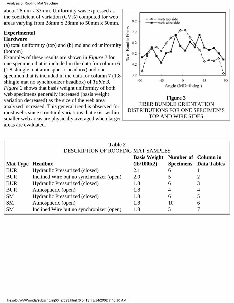
Figure 3FIBER BUNDLE ORIENTATION
DISTRIBUTIONS FOR ONE SPECIMEN’STOP AND WIRE SIDES
about 28mm x 33mm. Uniformity was expressed asthe coefficient of variation (CV%) computed for webareas varying from 28mm x 28mm to 50mm x 50mm.
ExperimentalHardware(a) total uniformity (top) and (b) md and cd uniformity(bottom)Examples of these results are shown in Figure 2 forone specimen that is included in the data for column 6(1.8 shingle mat atmospheric headbox) and onespecimen that is included in the data for column 7 (1.8shingle mat no synchronizer headbox) of Table 3.Figure 2 shows that basis weight uniformity of bothweb specimens generally increased (basis weightvariation decreased) as the size of the web areaanalyzed increased. This general trend is observed formost webs since structural variations that exist withinsmaller web areas are physically averaged when largerareas are evaluated.
Table 2DESCRIPTION OF ROOFING MAT SAMPLES
Basis Weight Number of Column inMat Type Headbox (lb/100ft2) Specimens Data TablesBUR Hydraulic Pressurized (closed) 2.1 6 1BUR Inclined Wire but no synchronizer (open) 2.0 5 2BUR Hydraulic Pressurized (closed) 1.8 6 3BUR Atmospheric (open) 1.8 4 4SM Hydraulic Pressurized (closed) 1.8 6 5SM Atmospheric (open) 1.8 10 6SM Inclined Wire but no synchronizer (open) 1.8 5 7
Analysis of Roofing Mat Structure
file:///D|/WWW/inda/subscrip/inj00_2/p23.html (6 of 13) [3/14/2002 7:40:10 AM]
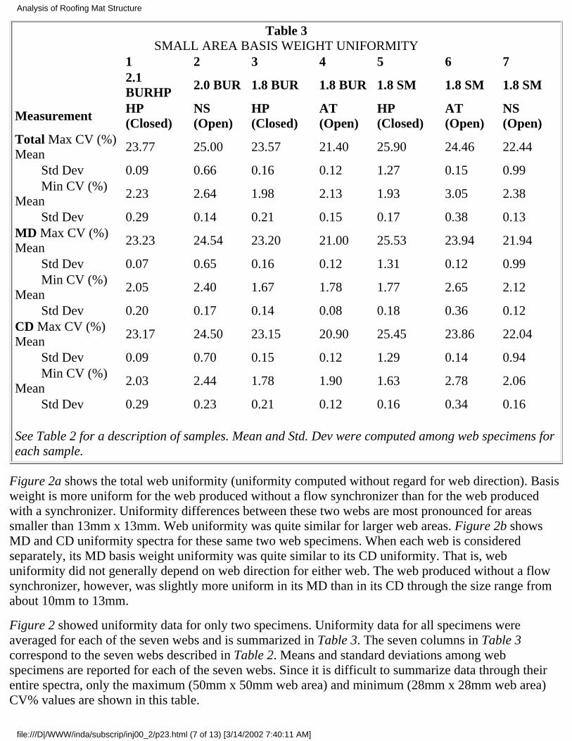
Table 3SMALL AREA BASIS WEIGHT UNIFORMITY
1 2 3 4 5 6 7
2.1BURHP 2.0 BUR 1.8 BUR 1.8 BUR 1.8 SM 1.8 SM 1.8 SM
Measurement HP(Closed)
NS(Open)
HP(Closed)
AT(Open)
HP(Closed)
AT(Open)
NS(Open)
Total Max CV (%)Mean
23.77 25.00 23.57 21.40 25.90 24.46 22.44
Std Dev 0.09 0.66 0.16 0.12 1.27 0.15 0.99 Min CV (%)Mean
2.23 2.64 1.98 2.13 1.93 3.05 2.38
Std Dev 0.29 0.14 0.21 0.15 0.17 0.38 0.13MD Max CV (%)Mean
23.23 24.54 23.20 21.00 25.53 23.94 21.94
Std Dev 0.07 0.65 0.16 0.12 1.31 0.12 0.99 Min CV (%)Mean
2.05 2.40 1.67 1.78 1.77 2.65 2.12
Std Dev 0.20 0.17 0.14 0.08 0.18 0.36 0.12CD Max CV (%)Mean
23.17 24.50 23.15 20.90 25.45 23.86 22.04
Std Dev 0.09 0.70 0.15 0.12 1.29 0.14 0.94 Min CV (%)Mean
2.03 2.44 1.78 1.90 1.63 2.78 2.06
Std Dev 0.29 0.23 0.21 0.12 0.16 0.34 0.16 See Table 2 for a description of samples. Mean and Std. Dev were computed among web specimens foreach sample.
Figure 2a shows the total web uniformity (uniformity computed without regard for web direction). Basisweight is more uniform for the web produced without a flow synchronizer than for the web producedwith a synchronizer. Uniformity differences between these two webs are most pronounced for areassmaller than 13mm x 13mm. Web uniformity was quite similar for larger web areas. Figure 2b showsMD and CD uniformity spectra for these same two web specimens. When each web is consideredseparately, its MD basis weight uniformity was quite similar to its CD uniformity. That is, webuniformity did not generally depend on web direction for either web. The web produced without a flowsynchronizer, however, was slightly more uniform in its MD than in its CD through the size range fromabout 10mm to 13mm.
Figure 2 showed uniformity data for only two specimens. Uniformity data for all specimens wereaveraged for each of the seven webs and is summarized in Table 3. The seven columns in Table 3correspond to the seven webs described in Table 2. Means and standard deviations among webspecimens are reported for each of the seven webs. Since it is difficult to summarize data through theirentire spectra, only the maximum (50mm x 50mm web area) and minimum (28mm x 28mm web area)CV% values are shown in this table.
Analysis of Roofing Mat Structure
file:///D|/WWW/inda/subscrip/inj00_2/p23.html (7 of 13) [3/14/2002 7:40:11 AM]
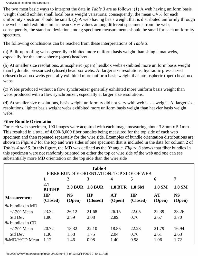
The two most basic ways to interpret the data in Table 3 are as follows: (1) A web having uniform basisweight should exhibit small local basis weight variations; consequently, the mean CV% for eachuniformity spectrum should be small. (2) A web having basis weight that is distributed uniformly throughthe web should exhibit similar mean CV% values among different specimens from the web;consequently, the standard deviation among specimen measurements should be small for each uniformityspectrum.
The following conclusions can be reached from these interpretations of Table 3.
(a) Built-up roofing webs generally exhibited more uniform basis weight than shingle mat webs,especially for the atmospheric (open) headbox.
(b) At smaller size resolutions, atmospheric (open) headbox webs exhibited more uniform basis weightthan hydraulic pressurized (closed) headbox webs. At larger size resolutions, hydraulic pressurized(closed) headbox webs generally exhibited more uniform basis weight than atmospheric (open) headboxwebs.
(c) Webs produced without a flow synchronizer generally exhibited more uniform basis weight thanwebs produced with a flow synchronizer, especially at larger size resolutions.
(d) At smaller size resolutions, basis weight uniformity did not vary with web basis weight. At larger sizeresolutions, lighter basis weight webs exhibited more uniform basis weight than heavier basis weightwebs.
Fiber Bundle OrientationFor each web specimen, 100 images were acquired with each image measuring about 3.8mm x 5.1mm.This resulted in a total of 4,000-8,000 fiber bundles being measured for the top side of each webspecimen and then repeated separately for the wire side. Examples of bundle orientation distributions areshown in Figure 3 for the top and wire sides of one specimen that is included in the data for column 2 ofTables 4 and 5. In this figure, the MD was defined as the 0o angle. Figure 3 shows that fiber bundles inthis specimen were not randomly oriented on either the top or wire side of the web and one can seesubstantially more MD orientation on the top side than the wire side
Table 4FIBER BUNDLE ORIENTATION: TOP SIDE OF WEB
1 2 3 4 5 6 7
2.1BURHP 2.0 BUR 1.8 BUR 1.8 BUR 1.8 SM 1.8 SM 1.8 SM
Measurement HP(Closed)
NS(Open)
HP(Closed)
AT(Open)
HP(Closed)
AT(Open)
NS(Open)
% bundles in MD +/-20o Mean 23.32 26.12 21.68 26.15 22.05 22.39 28.26 Std Dev 1.80 2.39 2.08 2.89 0.76 2.67 3.70% bundles in CD +/-20o Mean 20.72 18.32 22.10 18.85 22.23 21.79 16.94 Std Dev 1.30 1.58 1.75 2.04 0.76 2.61 2.63%MD/%CD Mean 1.12 1.46 0.98 1.40 0.98 1.06 1.72
Analysis of Roofing Mat Structure
file:///D|/WWW/inda/subscrip/inj00_2/p23.html (8 of 13) [3/14/2002 7:40:11 AM]
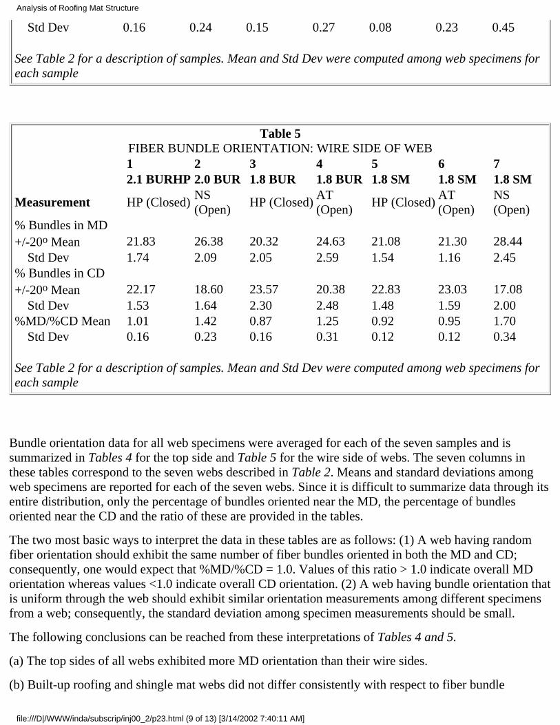
Std Dev 0.16 0.24 0.15 0.27 0.08 0.23 0.45 See Table 2 for a description of samples. Mean and Std Dev were computed among web specimens foreach sample
Table 5FIBER BUNDLE ORIENTATION: WIRE SIDE OF WEB
1 2 3 4 5 6 7 2.1 BURHP 2.0 BUR 1.8 BUR 1.8 BUR 1.8 SM 1.8 SM 1.8 SM
Measurement HP (Closed)NS(Open)
HP (Closed)AT(Open)
HP (Closed)AT(Open)
NS(Open)
% Bundles in MD+/-20o Mean 21.83 26.38 20.32 24.63 21.08 21.30 28.44 Std Dev 1.74 2.09 2.05 2.59 1.54 1.16 2.45% Bundles in CD+/-20o Mean 22.17 18.60 23.57 20.38 22.83 23.03 17.08 Std Dev 1.53 1.64 2.30 2.48 1.48 1.59 2.00%MD/%CD Mean 1.01 1.42 0.87 1.25 0.92 0.95 1.70 Std Dev 0.16 0.23 0.16 0.31 0.12 0.12 0.34 See Table 2 for a description of samples. Mean and Std Dev were computed among web specimens foreach sample
Bundle orientation data for all web specimens were averaged for each of the seven samples and issummarized in Tables 4 for the top side and Table 5 for the wire side of webs. The seven columns inthese tables correspond to the seven webs described in Table 2. Means and standard deviations amongweb specimens are reported for each of the seven webs. Since it is difficult to summarize data through itsentire distribution, only the percentage of bundles oriented near the MD, the percentage of bundlesoriented near the CD and the ratio of these are provided in the tables.
The two most basic ways to interpret the data in these tables are as follows: (1) A web having randomfiber orientation should exhibit the same number of fiber bundles oriented in both the MD and CD;consequently, one would expect that %MD/%CD = 1.0. Values of this ratio > 1.0 indicate overall MDorientation whereas values <1.0 indicate overall CD orientation. (2) A web having bundle orientation thatis uniform through the web should exhibit similar orientation measurements among different specimensfrom a web; consequently, the standard deviation among specimen measurements should be small.
The following conclusions can be reached from these interpretations of Tables 4 and 5.
(a) The top sides of all webs exhibited more MD orientation than their wire sides.
(b) Built-up roofing and shingle mat webs did not differ consistently with respect to fiber bundle
Analysis of Roofing Mat Structure
file:///D|/WWW/inda/subscrip/inj00_2/p23.html (9 of 13) [3/14/2002 7:40:11 AM]
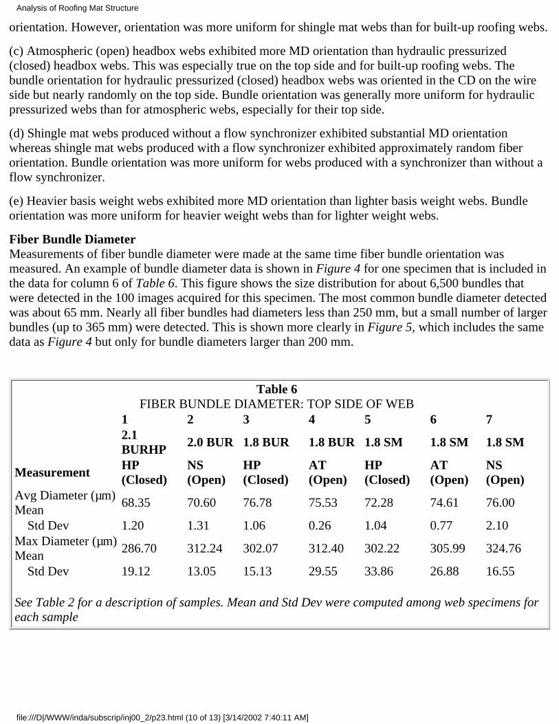
orientation. However, orientation was more uniform for shingle mat webs than for built-up roofing webs.
(c) Atmospheric (open) headbox webs exhibited more MD orientation than hydraulic pressurized(closed) headbox webs. This was especially true on the top side and for built-up roofing webs. Thebundle orientation for hydraulic pressurized (closed) headbox webs was oriented in the CD on the wireside but nearly randomly on the top side. Bundle orientation was generally more uniform for hydraulicpressurized webs than for atmospheric webs, especially for their top side.
(d) Shingle mat webs produced without a flow synchronizer exhibited substantial MD orientationwhereas shingle mat webs produced with a flow synchronizer exhibited approximately random fiberorientation. Bundle orientation was more uniform for webs produced with a synchronizer than without aflow synchronizer.
(e) Heavier basis weight webs exhibited more MD orientation than lighter basis weight webs. Bundleorientation was more uniform for heavier weight webs than for lighter weight webs.
Fiber Bundle DiameterMeasurements of fiber bundle diameter were made at the same time fiber bundle orientation wasmeasured. An example of bundle diameter data is shown in Figure 4 for one specimen that is included inthe data for column 6 of Table 6. This figure shows the size distribution for about 6,500 bundles thatwere detected in the 100 images acquired for this specimen. The most common bundle diameter detectedwas about 65 mm. Nearly all fiber bundles had diameters less than 250 mm, but a small number of largerbundles (up to 365 mm) were detected. This is shown more clearly in Figure 5, which includes the samedata as Figure 4 but only for bundle diameters larger than 200 mm.
Table 6FIBER BUNDLE DIAMETER: TOP SIDE OF WEB
1 2 3 4 5 6 7 2.1BURHP 2.0 BUR 1.8 BUR 1.8 BUR 1.8 SM 1.8 SM 1.8 SM
Measurement HP(Closed)
NS(Open)
HP(Closed)
AT(Open)
HP(Closed)
AT(Open)
NS(Open)
Avg Diameter (µm)Mean
68.35 70.60 76.78 75.53 72.28 74.61 76.00
Std Dev 1.20 1.31 1.06 0.26 1.04 0.77 2.10Max Diameter (µm)Mean
286.70 312.24 302.07 312.40 302.22 305.99 324.76
Std Dev 19.12 13.05 15.13 29.55 33.86 26.88 16.55 See Table 2 for a description of samples. Mean and Std Dev were computed among web specimens foreach sample
Analysis of Roofing Mat Structure
file:///D|/WWW/inda/subscrip/inj00_2/p23.html (10 of 13) [3/14/2002 7:40:11 AM]
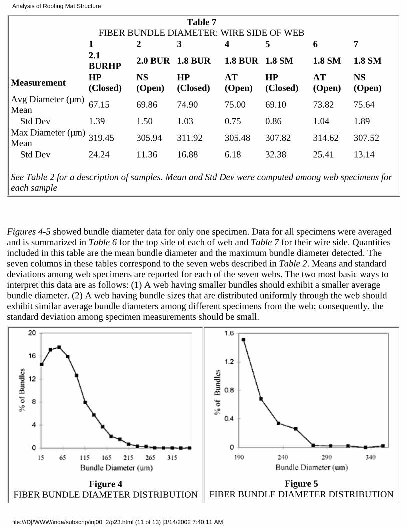
Table 7FIBER BUNDLE DIAMETER: WIRE SIDE OF WEB
1 2 3 4 5 6 7 2.1BURHP 2.0 BUR 1.8 BUR 1.8 BUR 1.8 SM 1.8 SM 1.8 SM
Measurement HP(Closed)
NS(Open)
HP(Closed)
AT(Open)
HP(Closed)
AT(Open)
NS(Open)
Avg Diameter (µm)Mean
67.15 69.86 74.90 75.00 69.10 73.82 75.64
Std Dev 1.39 1.50 1.03 0.75 0.86 1.04 1.89Max Diameter (µm)Mean
319.45 305.94 311.92 305.48 307.82 314.62 307.52
Std Dev 24.24 11.36 16.88 6.18 32.38 25.41 13.14 See Table 2 for a description of samples. Mean and Std Dev were computed among web specimens foreach sample
Figures 4-5 showed bundle diameter data for only one specimen. Data for all specimens were averagedand is summarized in Table 6 for the top side of each of web and Table 7 for their wire side. Quantitiesincluded in this table are the mean bundle diameter and the maximum bundle diameter detected. Theseven columns in these tables correspond to the seven webs described in Table 2. Means and standarddeviations among web specimens are reported for each of the seven webs. The two most basic ways tointerpret this data are as follows: (1) A web having smaller bundles should exhibit a smaller averagebundle diameter. (2) A web having bundle sizes that are distributed uniformly through the web shouldexhibit similar average bundle diameters among different specimens from the web; consequently, thestandard deviation among specimen measurements should be small.
Figure 4FIBER BUNDLE DIAMETER DISTRIBUTION
Figure 5FIBER BUNDLE DIAMETER DISTRIBUTION
Analysis of Roofing Mat Structure
file:///D|/WWW/inda/subscrip/inj00_2/p23.html (11 of 13) [3/14/2002 7:40:11 AM]
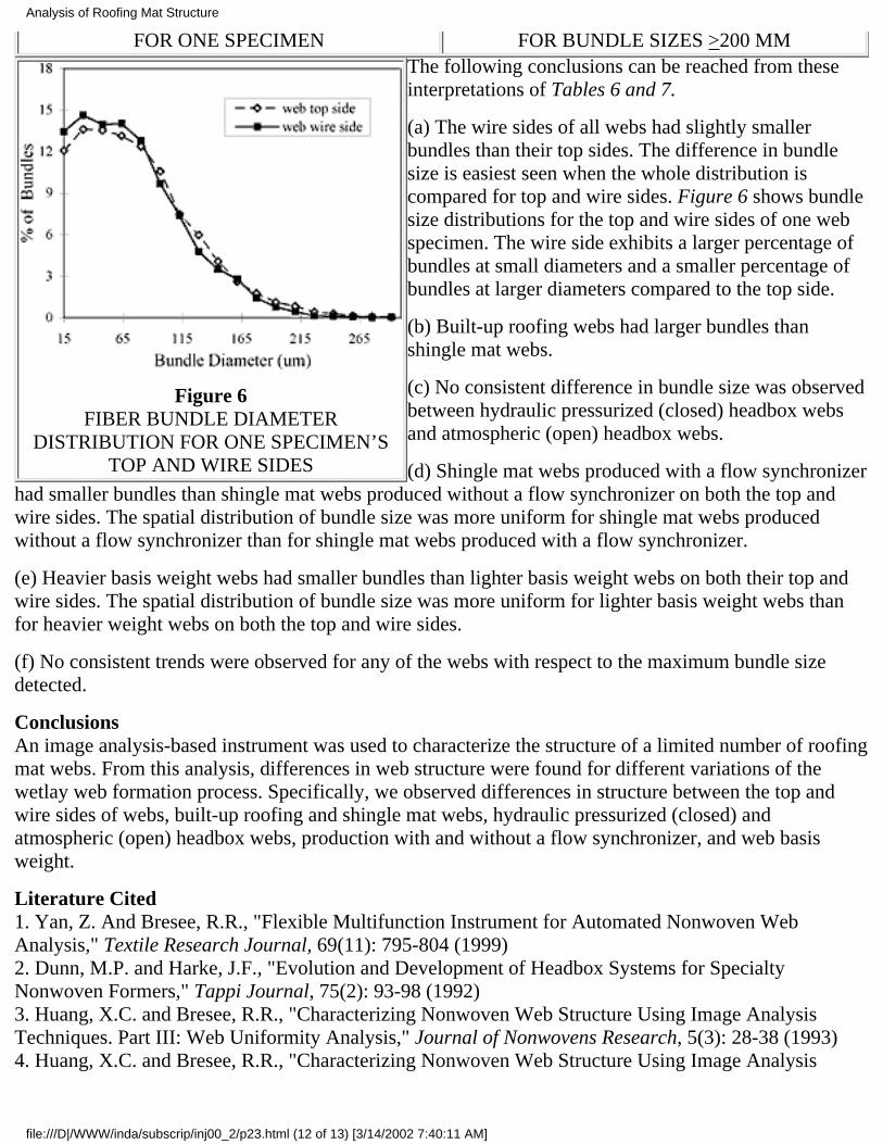
FOR ONE SPECIMEN FOR BUNDLE SIZES >200 MM
Figure 6FIBER BUNDLE DIAMETER
DISTRIBUTION FOR ONE SPECIMEN’STOP AND WIRE SIDES
The following conclusions can be reached from theseinterpretations of Tables 6 and 7.
(a) The wire sides of all webs had slightly smallerbundles than their top sides. The difference in bundlesize is easiest seen when the whole distribution iscompared for top and wire sides. Figure 6 shows bundlesize distributions for the top and wire sides of one webspecimen. The wire side exhibits a larger percentage ofbundles at small diameters and a smaller percentage ofbundles at larger diameters compared to the top side.
(b) Built-up roofing webs had larger bundles thanshingle mat webs.
(c) No consistent difference in bundle size was observedbetween hydraulic pressurized (closed) headbox websand atmospheric (open) headbox webs.
(d) Shingle mat webs produced with a flow synchronizerhad smaller bundles than shingle mat webs produced without a flow synchronizer on both the top andwire sides. The spatial distribution of bundle size was more uniform for shingle mat webs producedwithout a flow synchronizer than for shingle mat webs produced with a flow synchronizer.
(e) Heavier basis weight webs had smaller bundles than lighter basis weight webs on both their top andwire sides. The spatial distribution of bundle size was more uniform for lighter basis weight webs thanfor heavier weight webs on both the top and wire sides.
(f) No consistent trends were observed for any of the webs with respect to the maximum bundle sizedetected.
ConclusionsAn image analysis-based instrument was used to characterize the structure of a limited number of roofingmat webs. From this analysis, differences in web structure were found for different variations of thewetlay web formation process. Specifically, we observed differences in structure between the top andwire sides of webs, built-up roofing and shingle mat webs, hydraulic pressurized (closed) andatmospheric (open) headbox webs, production with and without a flow synchronizer, and web basisweight.
Literature Cited1. Yan, Z. And Bresee, R.R., "Flexible Multifunction Instrument for Automated Nonwoven WebAnalysis," Textile Research Journal, 69(11): 795-804 (1999)2. Dunn, M.P. and Harke, J.F., "Evolution and Development of Headbox Systems for SpecialtyNonwoven Formers," Tappi Journal, 75(2): 93-98 (1992)3. Huang, X.C. and Bresee, R.R., "Characterizing Nonwoven Web Structure Using Image AnalysisTechniques. Part III: Web Uniformity Analysis," Journal of Nonwovens Research, 5(3): 28-38 (1993)4. Huang, X.C. and Bresee, R.R., "Characterizing Nonwoven Web Structure Using Image Analysis
Analysis of Roofing Mat Structure
file:///D|/WWW/inda/subscrip/inj00_2/p23.html (12 of 13) [3/14/2002 7:40:11 AM]

Techniques. Part II: Fiber Orientation Analysis in Thin Webs," Journal of Nonwovens Research, 5(2):14-21 (1993)
- INJ
Return to International Nonwovens JournalHome Page & Table of Contents
Analysis of Roofing Mat Structure
file:///D|/WWW/inda/subscrip/inj00_2/p23.html (13 of 13) [3/14/2002 7:40:11 AM]
ORIGINAL PAPER/PEER-REVIEWED
A Study of the Airflow and Fiber Dynamicsin the Transport Chamber of a Sifting Air-laying System:Part 1By A. Pourmohammadi and S.J. Russell, Nonwovens Research Group, School of Textile Industries,and R. Brandean. D.B. Ingham and X. Wen. Centre for CFD, University of Leeds, U.K.
AbstractThe structural architecture of air-laid webs produced from short fibres is largely dependent on themanner in which fibres are assembled together during the web formation process. An improvedunderstanding of the behaviour of fibres during air-laying is essential to provide a basis for moreeffective engineering of the structure and properties of resulting fabrics. This two part paper presents theresults of a preliminary experimental study of the airflow and the fibre dynamics in a sifting air-layingprocess using LDV and high-speed photographic techniques. In Part 1 of the paper the airflowcharacteristics are investigated using Laser Doppler Velocimetry. In a commercially representativesifting air-laying machine it was established that the air velocity varies along the length and the height ofthe transport chamber. The variation is markedly increased by the rotation of the blades in the dispersingzone. Generally, the air velocity was found to increase from the top to the bottom of the transportchamber. With the rotating blades in operation the trend in the airflow velocity was characterised by a‘V’ shaped profile along the length of the chamber and was independent of the height of the chamber.(Part 2 of this paper will appear in the Fall, 2000 issue of the International Nonwovens Journal.)
IntroductionTo obtain high quality web structures with fibres evenly distributed in the web, a solid knowledge of thebasic principals of the fibre behaviour in the air-lay process is required. Various air-laying machinedesigns have been introduced which can be broadly classified as roller-based and sifting-based.
In this study, a sifting air-laying process of the Kroyer type [U.S. Patent 4,144,619] suitable forprocessing short fibres (2-12 mm) in the manufacture of air-laid material was used. In addition to the useof conventional pulp and fibre blend products this work has been concerned with the processing of shortfibre waste using this approach. In the air-laying process fibres are transported through an air stream andthe airflow characteristics are therefore very important in determining the final web structure.Toelucidate the airflow behaviour, Laser Doppler Velocimetry (LDV) was employed. Using this techniqueit was possible to obtain information on the airflow characteristics, which then can be used for
A Study of the Airflow and Fiber Dynamics
file:///D|/WWW/inda/subscrip/inj00_2/p31.html (1 of 7) [3/14/2002 8:56:20 AM]
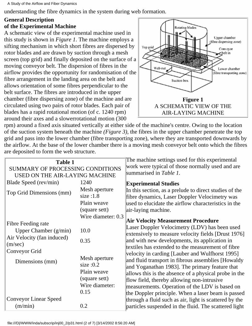
understanding the fibre dynamics in the system during web formation.
Figure 1A SCHEMATIC VIEW OF THE
AIR-LAYING MACHINE
General Descriptionof the Experimental MachineA schematic view of the experimental machine used inthis study is shown in Figure 1. The machine employs asifting mechanism in which short fibres are dispersed byrotor blades and are drawn by suction through a meshscreen (top grid) and finally deposited on the surface of amoving conveyor belt. The dispersion of fibres in theairflow provides the opportunity for randomisation of thefibre arrangement in the landing area on the belt andallows orientation of some fibres perpendicular to thebelt surface. The fibres are introduced in the upperchamber (fibre dispersing zone) of the machine and arecirculated using two pairs of rotor blades. Each pair ofblades has a rapid rotational motion (of c. 1240 rpm)around their axes and a slowerrotational motion (300rpm) around a fixed axis situated vertically at either side of the machine's centre. Owing to the locationof the suction system beneath the machine (Figure 3), the fibres in the upper chamber penetrate the topgrid and pass into the lower chamber (fibre transporting zone), where they are transported downwards bythe airflow. At the base of the lower chamber there is a moving mesh conveyor belt onto which the fibresare deposited to form the web structure.
Table 1SUMMARY OF PROCESSING CONDITIONS
USED ON THE AIR-LAYING MACHINEBlade Speed (rev/min) 1240
Top Grid Dimensions (mm)Mesh aperturesize :1.8
Plain weave(square sett)
Wire diameter: 0.3Fibre Feeding rate Upper Chamber (g/min) 10.0Air Velocity (fan induced)(m/sec)
0.35
Conveyor Grid
Dimensions (mm)Mesh aperturesize :0.2
Plain weave(square sett)
Wire diameter:0.15
Conveyor Linear Speed (m/min) 0.2
The machine settings used for this experimentalwork were typical of those normally used and aresummarised in Table 1.
Experimental StudiesIn this section, as a prelude to direct studies of thefibre dynamics, Laser Doppler Velocimetry wasused to elucidate the airflow characteristics in theair-laying machine.
Air Velocity Measurement ProcedureLaser Doppler Velocimetry (LDV) has been usedextensively to measure velocity fields [Drust 1976]and with new developments, its application intextiles has extended to the measurement of fibrevelocity in carding [Lauber and Wulfhorst 1995]and fluid transport in fibrous assemblies [Howaldyand Yoganathan 1983]. The primary feature thatallows this is the absence of a physical probe in theflow field, thereby allowing non-intrusivemeasurements. Operation of the LDV is based onthe Doppler principle. When a laser beam is passedthrough a fluid such as air, light is scattered by theparticles suspended in the fluid. The scattered light
A Study of the Airflow and Fiber Dynamics
file:///D|/WWW/inda/subscrip/inj00_2/p31.html (2 of 7) [3/14/2002 8:56:20 AM]
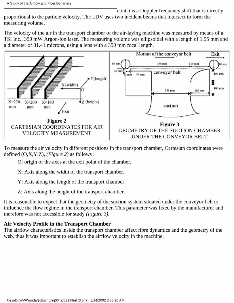
contains a Doppler frequency shift that is directlyproportional to the particle velocity. The LDV uses two incident beams that intersect to form themeasuring volume.
The velocity of the air in the transport chamber of the air-laying machine was measured by means of aTSI Inc., 350 mW Argon-ion laser. The measuring volume was ellipsoidal with a length of 1.55 mm anda diameter of 81.41 microns, using a lens with a 350 mm focal length.
Figure 2CARTESIAN COORDINATES FOR AIR
VELOCITY MEASUREMENT
Figure 3GEOMETRY OF THE SUCTION CHAMBER
UNDER THE CONVEYOR BELT
To measure the air velocity in different positions in the transport chamber, Cartesian coordinates weredefined (O,X,Y,Z), (Figure 2) as follows :
O: origin of the axes at the exit point of the chamber,
X: Axis along the width of the transport chamber,
Y: Axis along the length of the transport chamber
Z: Axis along the height of the transport chamber.
It is reasonable to expect that the geometry of the suction system situated under the conveyor belt toinfluence the flow regime in the transport chamber. This parameter was fixed by the manufacturer andtherefore was not accessible for study (Figure 3).
Air Velocity Profile in the Transport ChamberThe airflow characteristics inside the transport chamber affect fibre dynamics and the geometry of theweb, thus it was important to establish the airflow velocity in the machine.
A Study of the Airflow and Fiber Dynamics
file:///D|/WWW/inda/subscrip/inj00_2/p31.html (3 of 7) [3/14/2002 8:56:20 AM]
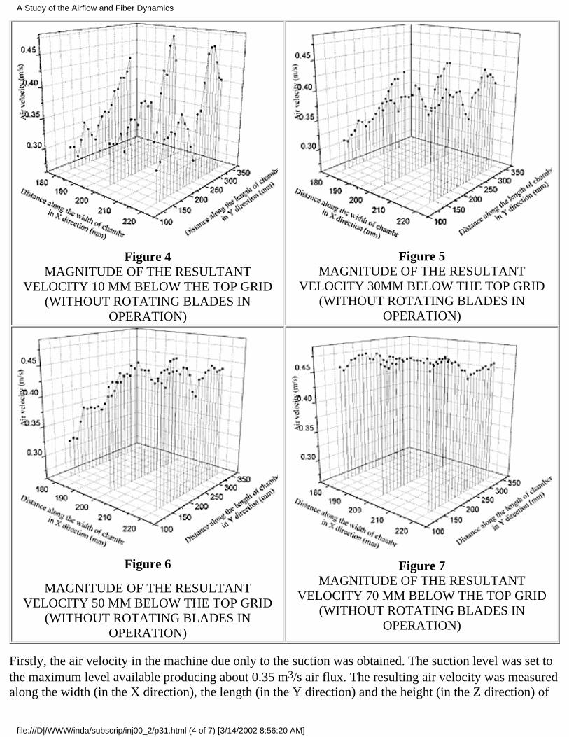
Figure 4MAGNITUDE OF THE RESULTANT
VELOCITY 10 MM BELOW THE TOP GRID(WITHOUT ROTATING BLADES IN
OPERATION)
Figure 5MAGNITUDE OF THE RESULTANT
VELOCITY 30MM BELOW THE TOP GRID(WITHOUT ROTATING BLADES IN
OPERATION)
Figure 6
MAGNITUDE OF THE RESULTANTVELOCITY 50 MM BELOW THE TOP GRID
(WITHOUT ROTATING BLADES INOPERATION)
Figure 7MAGNITUDE OF THE RESULTANT
VELOCITY 70 MM BELOW THE TOP GRID(WITHOUT ROTATING BLADES IN
OPERATION)
Firstly, the air velocity in the machine due only to the suction was obtained. The suction level was set tothe maximum level available producing about 0.35 m3/s air flux. The resulting air velocity was measuredalong the width (in the X direction), the length (in the Y direction) and the height (in the Z direction) of
A Study of the Airflow and Fiber Dynamics
file:///D|/WWW/inda/subscrip/inj00_2/p31.html (4 of 7) [3/14/2002 8:56:20 AM]
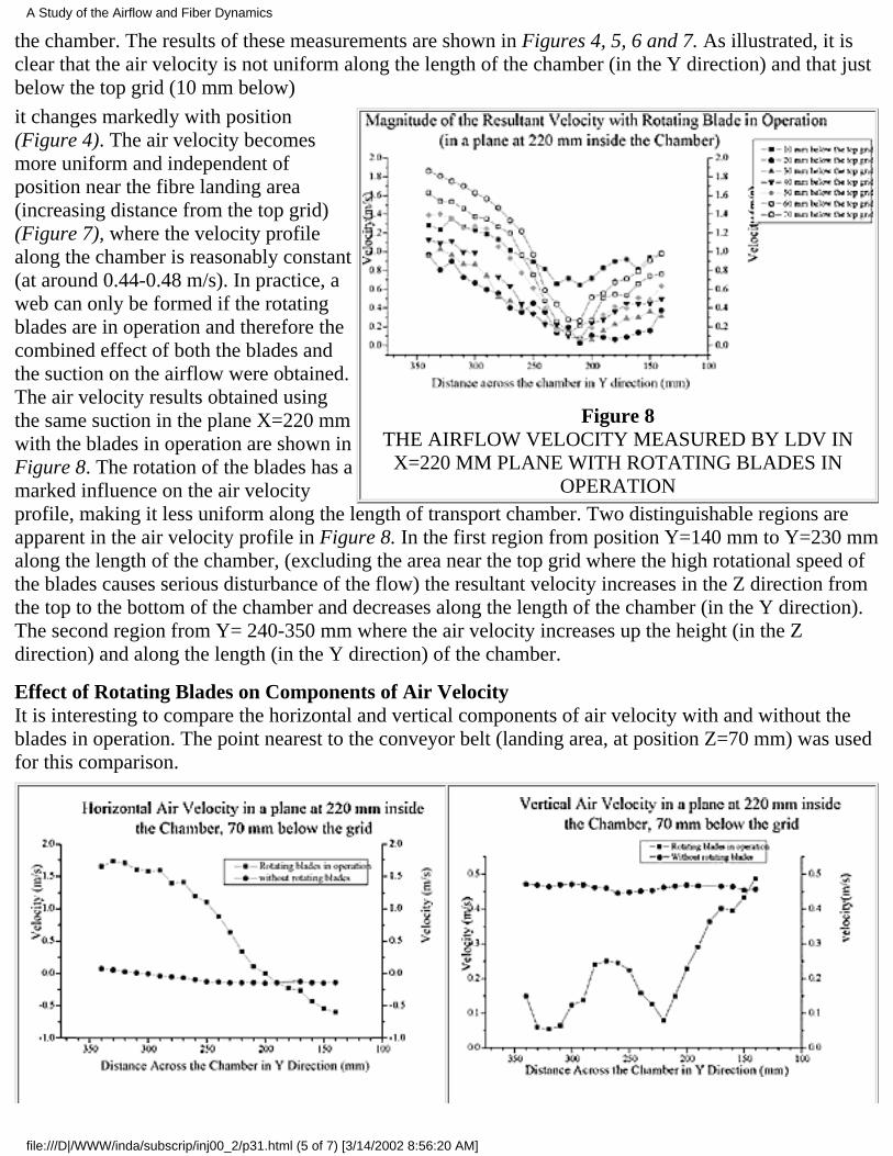
the chamber. The results of these measurements are shown in Figures 4, 5, 6 and 7. As illustrated, it isclear that the air velocity is not uniform along the length of the chamber (in the Y direction) and that justbelow the top grid (10 mm below)
Figure 8THE AIRFLOW VELOCITY MEASURED BY LDV IN
X=220 MM PLANE WITH ROTATING BLADES INOPERATION
it changes markedly with position(Figure 4). The air velocity becomesmore uniform and independent ofposition near the fibre landing area(increasing distance from the top grid)(Figure 7), where the velocity profilealong the chamber is reasonably constant(at around 0.44-0.48 m/s). In practice, aweb can only be formed if the rotatingblades are in operation and therefore thecombined effect of both the blades andthe suction on the airflow were obtained.The air velocity results obtained usingthe same suction in the plane X=220 mmwith the blades in operation are shown inFigure 8. The rotation of the blades has amarked influence on the air velocityprofile, making it less uniform along the length of transport chamber. Two distinguishable regions areapparent in the air velocity profile in Figure 8. In the first region from position Y=140 mm to Y=230 mmalong the length of the chamber, (excluding the area near the top grid where the high rotational speed ofthe blades causes serious disturbance of the flow) the resultant velocity increases in the Z direction fromthe top to the bottom of the chamber and decreases along the length of the chamber (in the Y direction).The second region from Y= 240-350 mm where the air velocity increases up the height (in the Zdirection) and along the length (in the Y direction) of the chamber.
Effect of Rotating Blades on Components of Air VelocityIt is interesting to compare the horizontal and vertical components of air velocity with and without theblades in operation. The point nearest to the conveyor belt (landing area, at position Z=70 mm) was usedfor this comparison.
A Study of the Airflow and Fiber Dynamics
file:///D|/WWW/inda/subscrip/inj00_2/p31.html (5 of 7) [3/14/2002 8:56:20 AM]
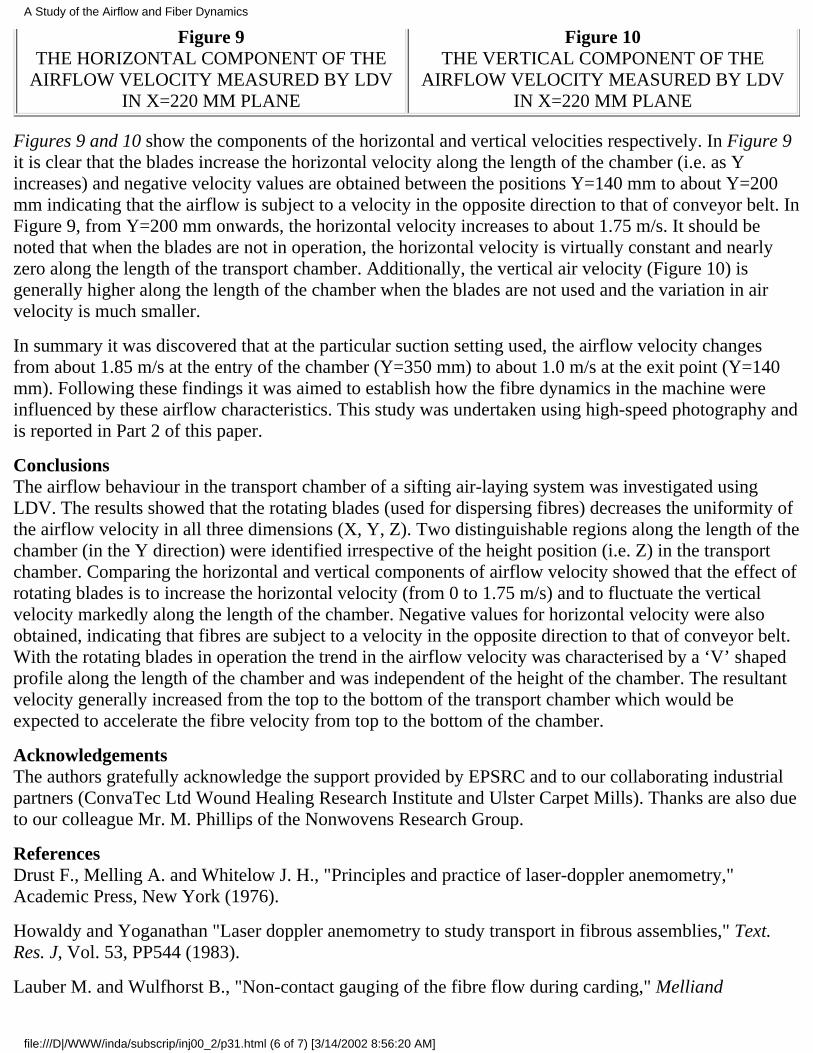
Figure 9THE HORIZONTAL COMPONENT OF THE
AIRFLOW VELOCITY MEASURED BY LDVIN X=220 MM PLANE
Figure 10THE VERTICAL COMPONENT OF THE
AIRFLOW VELOCITY MEASURED BY LDVIN X=220 MM PLANE
Figures 9 and 10 show the components of the horizontal and vertical velocities respectively. In Figure 9it is clear that the blades increase the horizontal velocity along the length of the chamber (i.e. as Yincreases) and negative velocity values are obtained between the positions Y=140 mm to about Y=200mm indicating that the airflow is subject to a velocity in the opposite direction to that of conveyor belt. InFigure 9, from Y=200 mm onwards, the horizontal velocity increases to about 1.75 m/s. It should benoted that when the blades are not in operation, the horizontal velocity is virtually constant and nearlyzero along the length of the transport chamber. Additionally, the vertical air velocity (Figure 10) isgenerally higher along the length of the chamber when the blades are not used and the variation in airvelocity is much smaller.
In summary it was discovered that at the particular suction setting used, the airflow velocity changesfrom about 1.85 m/s at the entry of the chamber (Y=350 mm) to about 1.0 m/s at the exit point (Y=140mm). Following these findings it was aimed to establish how the fibre dynamics in the machine wereinfluenced by these airflow characteristics. This study was undertaken using high-speed photography andis reported in Part 2 of this paper.
ConclusionsThe airflow behaviour in the transport chamber of a sifting air-laying system was investigated usingLDV. The results showed that the rotating blades (used for dispersing fibres) decreases the uniformity ofthe airflow velocity in all three dimensions (X, Y, Z). Two distinguishable regions along the length of thechamber (in the Y direction) were identified irrespective of the height position (i.e. Z) in the transportchamber. Comparing the horizontal and vertical components of airflow velocity showed that the effect ofrotating blades is to increase the horizontal velocity (from 0 to 1.75 m/s) and to fluctuate the verticalvelocity markedly along the length of the chamber. Negative values for horizontal velocity were alsoobtained, indicating that fibres are subject to a velocity in the opposite direction to that of conveyor belt.With the rotating blades in operation the trend in the airflow velocity was characterised by a ‘V’ shapedprofile along the length of the chamber and was independent of the height of the chamber. The resultantvelocity generally increased from the top to the bottom of the transport chamber which would beexpected to accelerate the fibre velocity from top to the bottom of the chamber.
AcknowledgementsThe authors gratefully acknowledge the support provided by EPSRC and to our collaborating industrialpartners (ConvaTec Ltd Wound Healing Research Institute and Ulster Carpet Mills). Thanks are also dueto our colleague Mr. M. Phillips of the Nonwovens Research Group.
ReferencesDrust F., Melling A. and Whitelow J. H., "Principles and practice of laser-doppler anemometry,"Academic Press, New York (1976).
Howaldy and Yoganathan "Laser doppler anemometry to study transport in fibrous assemblies," Text.Res. J, Vol. 53, PP544 (1983).
Lauber M. and Wulfhorst B., "Non-contact gauging of the fibre flow during carding," Melliand
A Study of the Airflow and Fiber Dynamics
file:///D|/WWW/inda/subscrip/inj00_2/p31.html (6 of 7) [3/14/2002 8:56:20 AM]
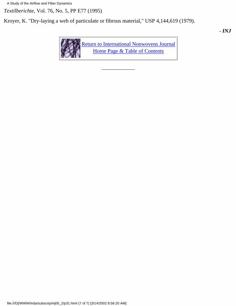
Textilberichte, Vol. 76, No. 5, PP E77 (1995)
Kroyer, K. "Dry-laying a web of particulate or fibrous material," USP 4,144,619 (1979).
- INJ
Return to International Nonwovens JournalHome Page & Table of Contents
A Study of the Airflow and Fiber Dynamics
file:///D|/WWW/inda/subscrip/inj00_2/p31.html (7 of 7) [3/14/2002 8:56:20 AM]
ORIGINAL PAPER/PEER-REVIEWED
Performance Of Nonwoven Cellulosic Composites ForAutomotive InteriorsBy D.V. Parikh, T.A. Calamari, USDA, ARS, SRRC, New Orleans, LA and J.C. Myatt, JanesvilleProducts, a Unit of Jason, Inc., Norfolk, OH
AbstractFinding methods to provide a quiet passenger compartment in a car are highly sought after by automobilemanufacturers. The ability to reduce noise inside the vehicle enhances the perceived value of the vehicleto the consumer and offers a competitive advantage to the manufacturer.
Several methods to reduce noise and its sources are employed, one of which reduces noise in thepassenger compartment using sound absorbing materials attached to various components such as doors,quarter panels, trunk sides and floors, headliners and others.
This study attempts to quantify the characteristics of several cellulosic-based nonwovens to act asefficient absorbers, reducing the overall sound level in the passenger compartment as measured byASTM C-384 "Impedance and Absorption of Acoustic Materials by the Impedance Tube Method."
The results of testing demonstrate that each of the cellulosic-based nonwoven composites contribute tothe absorptive properties of the components and are effective for overall noise reduction in the vehicle.The individual acoustic characteristics of the various vehicles determine the type and amount of materialrequired to provide the best results.
IntroductionVarious blends of cellulosic-based nonwovens manufactured by the carding and needlepunch process aretested for their ability to absorb sound energy. They are compared to targets of acoustic absorptionestablished by automotive manufacturers for use with vehicle interior trim components such as doorabsorbers, headliners, trunk liners and others with the goal of reducing the noise level in the vehicle.
DiscussionThe ability of a nonwoven material to absorb sound or unwanted noise in the passenger compartment ofthe vehicle is based on dissipation of the energy of the sound wave upon passing through the material andbeing redirected by the fibers, and also upon conversion of some of the energy into heat. The amount oforiginal energy less the remaining unabsorbed energy results in the measurement referred to as theabsorption coefficient. This absorption coefficient is often used to rank the order of different materials to
Performance of Nonwoven Components
file:///D|/WWW/inda/subscrip/inj00_2/p35.html (1 of 4) [3/14/2002 7:41:08 AM]
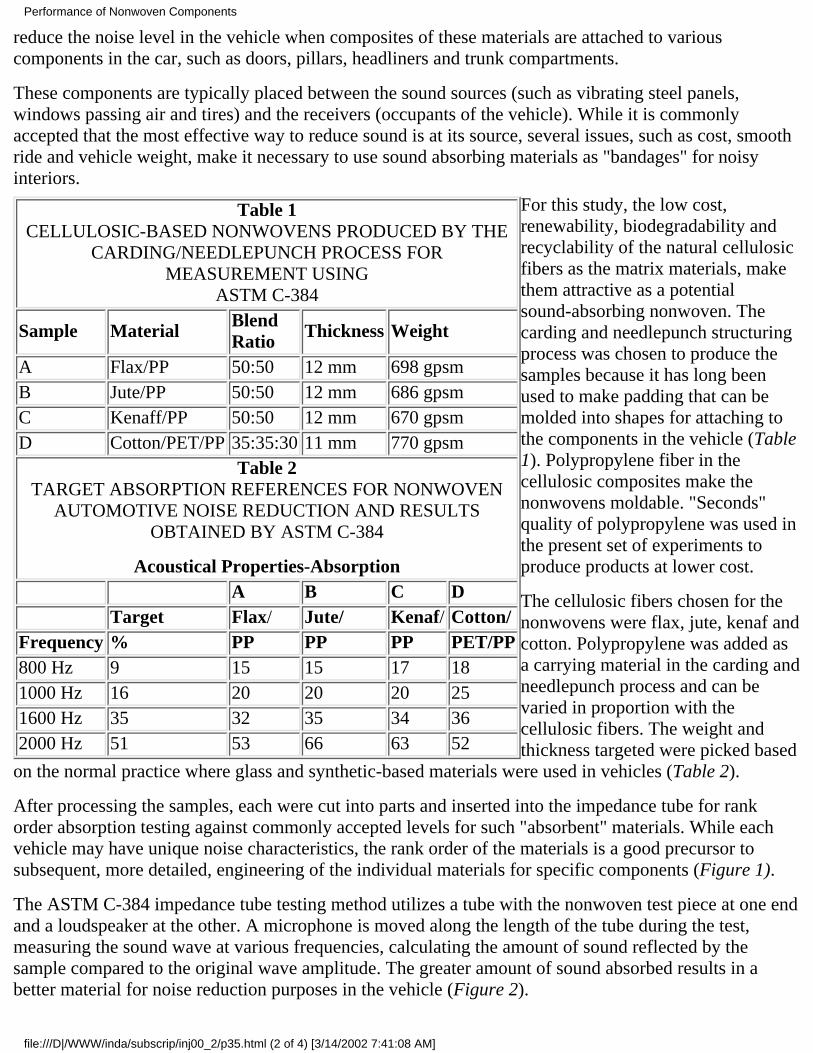
reduce the noise level in the vehicle when composites of these materials are attached to variouscomponents in the car, such as doors, pillars, headliners and trunk compartments.
These components are typically placed between the sound sources (such as vibrating steel panels,windows passing air and tires) and the receivers (occupants of the vehicle). While it is commonlyaccepted that the most effective way to reduce sound is at its source, several issues, such as cost, smoothride and vehicle weight, make it necessary to use sound absorbing materials as "bandages" for noisyinteriors.
Table 1CELLULOSIC-BASED NONWOVENS PRODUCED BY THE
CARDING/NEEDLEPUNCH PROCESS FORMEASUREMENT USING
ASTM C-384
Sample Material BlendRatio Thickness Weight
A Flax/PP 50:50 12 mm 698 gpsmB Jute/PP 50:50 12 mm 686 gpsmC Kenaff/PP 50:50 12 mm 670 gpsmD Cotton/PET/PP 35:35:30 11 mm 770 gpsm
Table 2TARGET ABSORPTION REFERENCES FOR NONWOVEN
AUTOMOTIVE NOISE REDUCTION AND RESULTSOBTAINED BY ASTM C-384
Acoustical Properties-Absorption A B C D Target Flax/ Jute/ Kenaf/ Cotton/Frequency % PP PP PP PET/PP800 Hz 9 15 15 17 181000 Hz 16 20 20 20 251600 Hz 35 32 35 34 362000 Hz 51 53 66 63 52
For this study, the low cost,renewability, biodegradability andrecyclability of the natural cellulosicfibers as the matrix materials, makethem attractive as a potentialsound-absorbing nonwoven. Thecarding and needlepunch structuringprocess was chosen to produce thesamples because it has long beenused to make padding that can bemolded into shapes for attaching tothe components in the vehicle (Table1). Polypropylene fiber in thecellulosic composites make thenonwovens moldable. "Seconds"quality of polypropylene was used inthe present set of experiments toproduce products at lower cost.
The cellulosic fibers chosen for thenonwovens were flax, jute, kenaf andcotton. Polypropylene was added asa carrying material in the carding andneedlepunch process and can bevaried in proportion with thecellulosic fibers. The weight andthickness targeted were picked based
on the normal practice where glass and synthetic-based materials were used in vehicles (Table 2).
After processing the samples, each were cut into parts and inserted into the impedance tube for rankorder absorption testing against commonly accepted levels for such "absorbent" materials. While eachvehicle may have unique noise characteristics, the rank order of the materials is a good precursor tosubsequent, more detailed, engineering of the individual materials for specific components (Figure 1).
The ASTM C-384 impedance tube testing method utilizes a tube with the nonwoven test piece at one endand a loudspeaker at the other. A microphone is moved along the length of the tube during the test,measuring the sound wave at various frequencies, calculating the amount of sound reflected by thesample compared to the original wave amplitude. The greater amount of sound absorbed results in abetter material for noise reduction purposes in the vehicle (Figure 2).
Performance of Nonwoven Components
file:///D|/WWW/inda/subscrip/inj00_2/p35.html (2 of 4) [3/14/2002 7:41:08 AM]
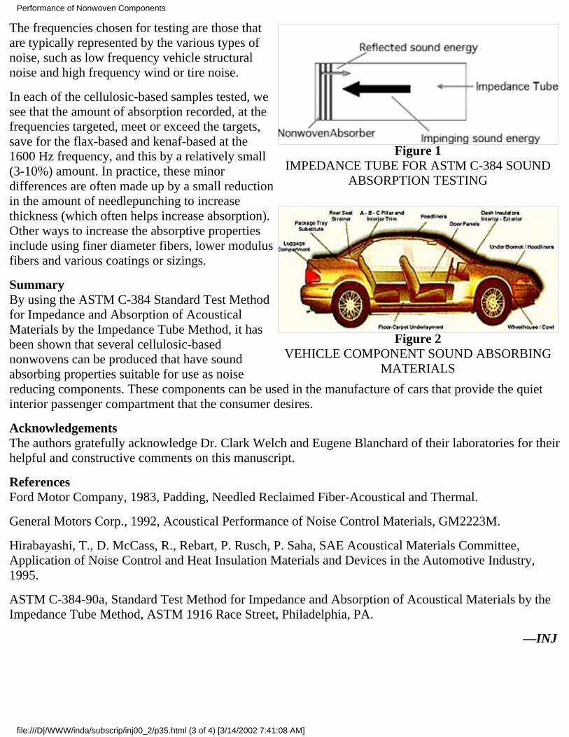
Figure 1IMPEDANCE TUBE FOR ASTM C-384 SOUND
ABSORPTION TESTING
Figure 2VEHICLE COMPONENT SOUND ABSORBING
MATERIALS
The frequencies chosen for testing are those thatare typically represented by the various types ofnoise, such as low frequency vehicle structuralnoise and high frequency wind or tire noise.
In each of the cellulosic-based samples tested, wesee that the amount of absorption recorded, at thefrequencies targeted, meet or exceed the targets,save for the flax-based and kenaf-based at the1600 Hz frequency, and this by a relatively small(3-10%) amount. In practice, these minordifferences are often made up by a small reductionin the amount of needlepunching to increasethickness (which often helps increase absorption).Other ways to increase the absorptive propertiesinclude using finer diameter fibers, lower modulusfibers and various coatings or sizings.
SummaryBy using the ASTM C-384 Standard Test Methodfor Impedance and Absorption of AcousticalMaterials by the Impedance Tube Method, it hasbeen shown that several cellulosic-basednonwovens can be produced that have soundabsorbing properties suitable for use as noisereducing components. These components can be used in the manufacture of cars that provide the quietinterior passenger compartment that the consumer desires.
AcknowledgementsThe authors gratefully acknowledge Dr. Clark Welch and Eugene Blanchard of their laboratories for theirhelpful and constructive comments on this manuscript.
ReferencesFord Motor Company, 1983, Padding, Needled Reclaimed Fiber-Acoustical and Thermal.
General Motors Corp., 1992, Acoustical Performance of Noise Control Materials, GM2223M.
Hirabayashi, T., D. McCass, R., Rebart, P. Rusch, P. Saha, SAE Acoustical Materials Committee,Application of Noise Control and Heat Insulation Materials and Devices in the Automotive Industry,1995.
ASTM C-384-90a, Standard Test Method for Impedance and Absorption of Acoustical Materials by theImpedance Tube Method, ASTM 1916 Race Street, Philadelphia, PA.
—INJ
Performance of Nonwoven Components
file:///D|/WWW/inda/subscrip/inj00_2/p35.html (3 of 4) [3/14/2002 7:41:08 AM]