Embed Size (px)
Citation preview
Moment of Inertia & Rotational Energy
Keelen GarzaObjective In this lab, the physical nature of the moment of inertia and the conservation law of mechanical energy involving rotational motion will be examined and tested experimentally. Equipment List The rotary motion kit (shown on the right); a LabPro unit; a smart pulley (SP); string; a mass holder and a set of masses; a plastic ruler and a meter stick; a digital caliper; ACCULAB VI-1200 mass scale. Theoretical Background This lab extends the exploration of the Newtonian Mechanics to rotational motion. Moment of Inertia
Analogous to the “mass” in translational motion, the “moment of inertia”, I, describes how difficult it is to change an object’s rotational motion; specifically speaking, the angular velocity. “I” is defined as the ratio of the “torque” (τ ) to the angular acceleration (α ) and appears in Newton’s second law of motion for rotational motion as follows:
ατ I= For objects with simple geometrical shapes, it is possible to calculate their moments of inertia with the assistance of calculus. The table below summarizes the equations for computing “I” of objects of some common geometrical shapes. solid disk or cylinder12𝑀𝑅2
thin rod rotating about the center 112𝑀𝐿2
thin loop or point mass 𝑀𝑅2
Thick ring with inner and outer radius Rin and Rout 12𝑀(𝑅𝑜𝑢𝑡2 + 𝑅𝑖𝑛2 )
thin rod rotating about one end 13𝑀𝐿2
International Journal of Scientific & Engineering Research, Volume 5, Issue 7, July-2014 ISSN 2229-5518
1557
IJSER © 2014 http://www.ijser.org
IJSER
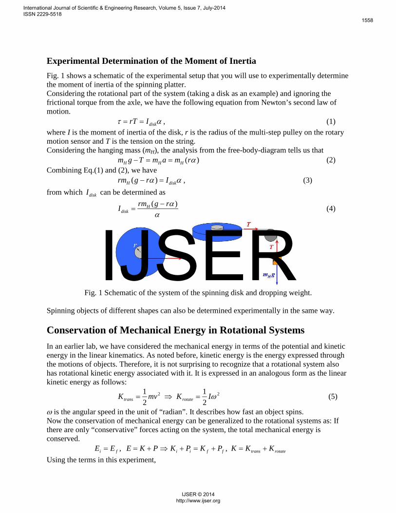
Experimental Determination of the Moment of Inertia Fig. 1 shows a schematic of the experimental setup that you will use to experimentally determine the moment of inertia of the spinning platter. Considering the rotational part of the system (taking a disk as an example) and ignoring the frictional torque from the axle, we have the following equation from Newton’s second law of motion.
ατ diskIrT == , (1) where I is the moment of inertia of the disk, r is the radius of the multi-step pulley on the rotary motion sensor and T is the tension on the string. Considering the hanging mass (mH), the analysis from the free-body-diagram tells us that
)( αrmamTgm HHH ==− (2) Combining Eq.(1) and (2), we have αα diskH Irgrm =− )( , (3) from which diskI can be determined as
α
α )( rgrmI Hdisk
−= (4)
Fig. 1 Schematic of the system of the spinning disk and dropping weight.
Spinning objects of different shapes can also be determined experimentally in the same way.
Conservation of Mechanical Energy in Rotational Systems In an earlier lab, we have considered the mechanical energy in terms of the potential and kinetic energy in the linear kinematics. As noted before, kinetic energy is the energy expressed through the motions of objects. Therefore, it is not surprising to recognize that a rotational system also has rotational kinetic energy associated with it. It is expressed in an analogous form as the linear kinetic energy as follows:
22
21
21 ωIKmvK rotatetrans =⇒= (5)
ω is the angular speed in the unit of “radian”. It describes how fast an object spins. Now the conservation of mechanical energy can be generalized to the rotational systems as: If there are only “conservative” forces acting on the system, the total mechanical energy is conserved.
rotatetransffiifi KKKPKPKPKEEE +=+=+⇒+== ,, Using the terms in this experiment,
International Journal of Scientific & Engineering Research, Volume 5, Issue 7, July-2014 ISSN 2229-5518
1558
IJSER © 2014 http://www.ijser.org
IJSER
fHfdiskfHiHidiskiH ghmIvmghmIvm ++=++⇒ 2222
21
21
21
21 ωω (6)
In this equation, mH is the mass of the hanging weight, and v its speed. Idisk is the moment of inertia of the disk, and ω is the angular speed. h is the height of the hanging weight measured from the ground. In the experiment, the hanging weight and the disk are released from rest, and we measure the final speeds as the hanging weight reaches the floor. So Equation 6 becomes
22
21
21
fdiskfHiH Ivmghm ω+= (7)
It is also noticed that the linear motion of the hanging weight is related to the spinning rate of the disk through the equation, ωrv = , where r is the radius of the multi-step pulley around which the string wraps. Using this equation, Equation 7 becomes
222
21
21
fdiskfHiH Irmghm ωω += . (8)
In this equation, Idisk is the moment of inertia of the disk, and r is the radius of the multi-step pulley. Solving this equation for ωf,
2,2
rmIghm
Hdisk
iHtheof +
=ω . (9)
You will use this equation to calculate the theoretical values of the final angular speeds.
Quantities in Translational Motions Analogous Quantities in Rotational Motions M (mass) I (moment of inertia)
v (velocity) ω (angular velocity) mvp = (linear momentum) ωIL = (angular momentum) 2
21 mv (linear kinetic energy) 2
21 ωI (rotational kinetic energy)
Experimental Procedure Setup and Use the LoggerPro program
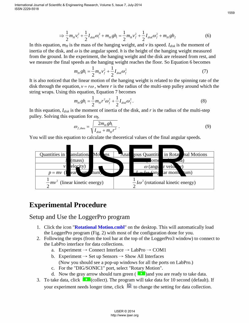
1. Click the icon "Rotational Motion.cmbl" on the desktop. This will automatically load the LoggerPro program (Fig. 2) with most of the configuration done for you.
2. Following the steps (from the tool bar at the top of the LoggerPro3 window) to connect to the LabPro interface for data collections.
a. Experiment → Connect Interface → LabPro → COM1 b. Experiment → Set up Sensors → Show All Interfaces
(Now you should see a pop-up windows for all the ports on LabPro.) c. For the "DIG/SONIC1" port, select "Rotary Motion". d. Now the gray arrow should turn green ( )and you are ready to take data.
3. To take data, click (collect). The program will take data for 10 second (default). If your experiment needs longer time, click to change the setting for data collection.
International Journal of Scientific & Engineering Research, Volume 5, Issue 7, July-2014 ISSN 2229-5518
1559
IJSER © 2014 http://www.ijser.org
IJSER
You should see both the angular position and angular speed as functions of time displayed in real-time in the graphs. If the data is not to your satisfaction, simply repeat the experiment and take another data.
4. To save the data, follow "File → Export As → CSV" to export your current data in "*.csv" format. Wisely choose the filename to label the data. Since your data will be overwritten by new data, you should export the data BEFORE running next experiment.
Fig. 2 The screenshot of the LoggerPro3 interface for recording and analyzing the rotational motion data.
Collect Data In the experiment, a hanging mass is attached to a string pulling the 3-step pulley (3SP) on the rotary motion sensor. The hanging mass will be released from rest at a measured height. As the hanging mass falls, it pulls the string to spin the disk and causes the angular speed of the disk to increase. The angular motion of the disk is recorded by LabPro and the LoggerPro3 program.
1. Measure and record the following quantities of the Aluminum disk: mass (M); diameter (D); calculated theoretical moment of inertia 𝐼𝑡ℎ𝑒𝑜 = 1
2𝑀𝑅2 = 1
8𝑀𝐷2.
2. Set up the rotary motion sensor and the disk as shown in Fig. 3. 3. The direction and tilt angle of the SP should be adjusted so that the SP is aligned with the
direction of the string and the string pulls the 3SP horizontally. 4. Attach the mass hanger to the string on the 3SP. The string should wrap around the
largest "step". (You may choose the "middle" step if more appropriate for your setup. However, you need to use the corresponding radius for your calculations then.) The length of string must be long enough so that the hanging mass hits the floor before the string is completely unwrapped.
5. Put a 10 g weight on the hanger and measure the total hanging mass, mH.
International Journal of Scientific & Engineering Research, Volume 5, Issue 7, July-2014 ISSN 2229-5518
1560
IJSER © 2014 http://www.ijser.org
IJSER
6. Rotate the disk until the hanging mass reaches a height of hi = 75 cm. Hold the disk at rest.
7. Click , then release the disk. You should see data plotting as the mass drops. The data must record the motion until ~1 second after the hanging mass hits the floor.
8. Export the data in "*.csv" format. Find the angular acceleration (α) by finding the slope of the linearly rising portion of the ω(t) plot and the final angular speed, ωf,exp, using LoggerPro3 (discussed in "Data Analysis" below). Estimate the uncertainties of α and ωf,exp.
9. Repeat step 5-8 with different weights (15g, 20g, 30g, and 40g) released from the same initial height (hi = 75 cm). Remember to record the total hanging mass, mH.
10. (optional) Remove the disk from the rotary motion sensor, and mount the hallow aluminum rod on the pulley. Attach the masses to the rod with the locking screws. Find the moment of inertial of the "rod+masses" system. Change the positions of the masses (moving them closer or farther from the axis), and find how the moment of inertia changes.
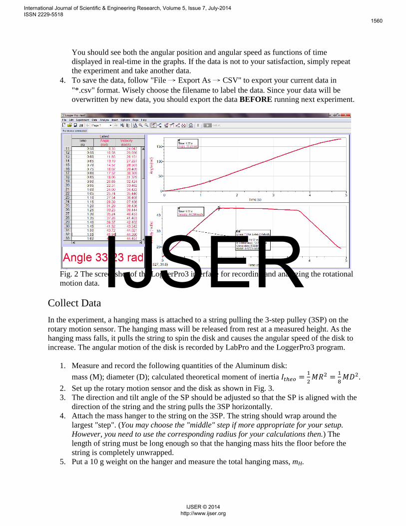
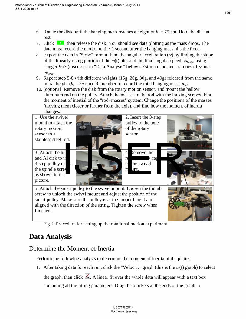
1. Use the swivel mount to attach the rotary motion sensor to a stainless steel rod.
2. Insert the 3-step pulley to the axle of the rotary sensor.
3. Attach the hub and Al disk to the 3-step pulley using the spindle screw, as shown in the picture.
4. Remove the rubber screw cap on the swivel mount.
5. Attach the smart pulley to the swivel mount. Loosen the thumb screw to unlock the swivel mount and adjust the position of the smart pulley. Make sure the pulley is at the proper height and aligned with the direction of the string. Tighten the screw when finished.
Fig. 3 Procedure for setting up the rotational motion experiment. Data Analysis Determine the Moment of Inertia
Perform the following analysis to determine the moment of inertia of the platter.
1. After taking data for each run, click the "Velocity" graph (this is the ω(t) graph) to select
the graph, then click . A linear fit over the whole data will appear with a text box
containing all the fitting parameters. Drag the brackets at the ends of the graph to
International Journal of Scientific & Engineering Research, Volume 5, Issue 7, July-2014 ISSN 2229-5518
1561
IJSER © 2014 http://www.ijser.org
IJSER
determine the specific range of data that you want to fit. Find the slope of the rising part
in the "Velocity" plot for each run. The slope is the angular acceleration, α, produced by
the hanging weight.
2. Calculate the value, )( αrgrmH − for each hanging mass, mH.
3. Calculate the Iexp1 with Equation (4) for each hanging mass.
4. Plot )( αrgrmH − as a function of α,(" )( αrgrmH − " in y-axis and "α"in x-axis). and
determine the slope of the graph. According to Equation (3), the slope should also be the
moment of inertia of the disk (Iexp2). Use Excel to find the uncertainty in the slope,
δ(Iexp2). (Ask the instructor for help if needed.)
5. Estimate the % uncertainty of Iexp2 using %100)(
2exp
2exp ×IIδ
.
6. Compare Iexp1 and Iexp2 with Itheo.
Conservation of Mechanical Energy Perform the following calculations for the same set of data.
7. Find the final angular speed on each "Velocity" graph by clicking . A cursor will
appear to allow you specify which data point to look at. Move to the "kink" at the end of
the rising section (this is when the hanging mass hits the floor). The "Velocity" (angular
speed) of this point is the ωf,exp.
8. Calculate the final speed of the hanging mass from the final angular speed using
exp,exp, ff rv ω= .
9. Use Itheo as Idisk. and calculate the theoretical final angular speed, ωf,theo, using Eqn. (9).
10. Calculate the % Difference between ωf,exp and ωf,theo.
11. Calculate the initial potential energy of the system using,
iHi ghmP =
12. Calculate the final kinetic energy using,
2exp,
2exp, 2
121
fHfdiskf vmIK += ω
13. Calculate the ratio if PK .
14. Plot Kf (y-axis) as a function of Pi (x-axis) and determine the slope and y-intercept.
International Journal of Scientific & Engineering Research, Volume 5, Issue 7, July-2014 ISSN 2229-5518
1562
IJSER © 2014 http://www.ijser.org
IJSER
Selected Questions 1. The Equation (4) used for calculating Iexp1 does not consider the internal torque generated
by the friction on the axle.
Would this frictional torque affect the values of Iexp1? If yes, how? If no, why?
Would this frictional torque affect the values of Iexp2 obtained from the slope of Plot 1? If
yes, how? If no, why?
(Hint: one of them is not affected by the presence of the friction if the friction is constant.)
2. For the conservation of energy experiment, what effect does friction have on this
conservation principle? Is this a source of random or systematic error? Why?
International Journal of Scientific & Engineering Research, Volume 5, Issue 7, July-2014 ISSN 2229-5518
1563
IJSER © 2014 http://www.ijser.org
IJSER