Embed Size (px)
Citation preview
International Journal of Recent Technology and Engineering (IJRTE)
ISSN: 2277-3878, Volume-8 Issue-2, July 2019
526
Published By:
Blue Eyes Intelligence Engineering
& Sciences Publication Retrieval Number: B1590078219/19©BEIESP
DOI: 10.35940/ijrte.B1590.078219
Speed Regulation Enhancement for SRM Drive in
PHEV Applications by using Hybrid Fuzzy
Logic controller
A.S. Veerendra, M.R. Mohamed, M.H. Sulaiman, K. Peddakapu, K.Sudhakar, Sreenath sukumaran
Abstract: Speed regulation enhancement of a Switched
Reluctance Motor (SRM) Driveby using modularfront-
endintegrated multilevel converter for plug-in hybrid electric
vehicle (PHEV) applications are studied and evaluated in this
paper. Theoperating modes of the system are basing on Turn-On
&Turn OFF of the switches in the converter circuit. In order to
achievefast demagnetization and excitation, during generator
driving mode, the battery bank is used to elevate the phase
voltage. To get the multiple voltage responses and torque
increment, an additional charging capacitor and a reframed
four-level structure from the converter during battery driving
mode is required. A hybrid Fuzzy Logic Controlleris proposedin
orderto control the speed of the SRM motor. This paper mainly
focuses on the comparison of the hybrid fuzzy logic controller
with conventional P & PI and to prove the proposed controller
provides the best performance and high robustness compared to a
conventional P & PI controller. Matlab / Simulink is used to
simulate.
Keywords: hybrid Fuzzy logic controller, P & PI controller
Integrated multi-level converter, electric vehicles (EVs), hybrid
EVs (HEVs), switched reluctance motors (SRMs).
I. INTRODUCTION
With continuous effort to reduce the greenhouse gas
emission that it is majorly caused due to the Internal
combustion engine. To protect the environment, researchers
are exploring the alternative fuels. Therefore, electric
vehicles (EVs) have involvedcollective attention over the
decades[1-4].These electric vehicles run purely with a
battery having less pollution, better fuel economy and
efficiency Contrasted to conventional internal combustion
engine (ICE)-based vehicles. However, the EV has some
limitation like high battery weight, short driving range and
high charging time. As a result,to compromisepure battery-
powered vehicles, Hybrid electric vehicles (HEVs) and
plug-in HEVs (PHEVs) are gaininga choice of attraction[5-
7].
Revised Manuscript Received on July 07, 2019.
A. S. Veerendra, Sustainable Energy & Power Electronics Research
(Super) Cluster University Malaysia, Pahang, Malaysia
M.R. Mohamed, Sustainable Energy & Power Electronics Research
(Super) Cluster, University Malaysia, Pahang, Malaysia.
K. Sudhakar, Energy Center, MANIT, Bhopal
In HEV and PHEV, motors are playing a prominent role.
Among all types of motors permanent-magnet synchronous
motors (PMSMs) are majorly using in-vehicle
manufacturers due tohigh power density and high-level
engine drive technology[8, 9], but the material used in
magnets are usually rare earth materials like neodymium
(Nd) and dysprosium (Dy).Due to that, PMSM ishaving
some limitation such as high cost and high-temperature
permanent magnets.Therefore manufacturers exploring a
solution for rare-earth-free magnets[10]. Hence to avoid the
problems in PMSM, Switched reluctance motors (SRMs)
are known to provide longer service time and a more cost-
effective option and also works in a harsh environment
because of its simpler, more robust design without any
permanent rotor windings and magnets gives high
efficiency, high reliability, outstanding fault tolerance
capability and high starting torque in initial accelerations
[11, 12]. From [13], PHEV drivetrain based on SRM
comprises of a power control unit that includes an integrated
converter and controller,an energy storage unit, an Internal
Combustion Engine, and an SRM that operates as a traction
motor. The Simulink models are designed separately for PI
& hybrid Fuzzy logic controller and are compared with their
performance. The Switched Reluctance Motor is an
electrical engine running through a torque of reluctance. The
controllers used at this time are the conventional PI
controller, and the other one is Fuzzy Logic Controller
based on Artificial Intelligence. The PI Controller
proportional integral controller) is the PID controller's most
special case where the error derivative is not used. Hybrid
Fuzzy logic haslogical values that resemble human
reasoning. HFLC has various applications in industrial
control, especially where it is very difficult to apply these
conventional control design techniques. A broad review of
the modelling, design, simulation and analysis and control
of SRM machines [14] has been carried out.
II. CENTRAL-TAPPED WINDINGS SRM
TOPOLOGY
Basing on charging methods for PHEV, a split converter
methodology is designed for PMSM motors to charge from
Grid without basing on charging stations; however, it
requires different winding structure and also only suitable
for ac charging. Hence an eight pole four phase SRM is
proposed in this paper having central-tapped node and half-
bridge asymmetric drive
topology.To understand front-
end modular converter motor
drive structure, an
brought to you by COREView metadata, citation and similar papers at core.ac.uk
provided by UMP Institutional Repository
Speed Regulation Enhancement for SRM Drive in PHEV Applications by using Hybrid Fuzzy
Logic controller
527
Published By:
Blue Eyes Intelligence Engineering
& Sciences Publication Retrieval Number: B1590078219/19©BEIESP DOI: 10.35940/ijrte.B1590.078219
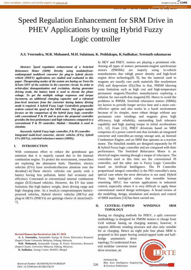
asymmetric half-bridge converter topology is exploited as
revealed in Fig.1.Entailing of Eight metal–oxide–
semiconductor field effect transistors (MOSFETs), eight
freewheeling diodes, and two inputs filter capacitors (Caband
Ccdare). The winding inductances of phases A, B, C, and D,
respectively, are La14, La23, Lb14, Lb23, Lc14, Lc23, Ld14, and
Ld23. NA, NB, NC, and ND are the four-phase central-
tapped nodes. It consisting of two converters such as
Converter I drives phases A and B and share the voltage of
the E1 battery,while the Converter II drives the C and D
phases and share E2. From Figure 1; converters operate in
two modes: driving and charging. During driving mode,the
converter is equivalent to a conventional half-bridge
asymmetric topology, and the charging plug is inactive.
Because NA and ND are kept open, seems to be there is no
current flowing between NB and NC, i.e. converters I and II
operate separately.During Charging modeConverters I and II
are in charging state when the charging plug is connected to
an external source.
Fig. 1. Central tapped front-end proposed Topology
Fig. 2. SRM block diagram control.
III. CONTROL STRATEGIES FOR SRM DRIVE
During driving mode, the standstill battery balance and
unequal SoC basing on the split convertercontrol strategyis
explained in this section.
A. Split converter Control Strategy during Drive
The balance of the phase voltage is determined by
(1)
Where;
Uab = voltage of the phase R = resistance of the phase L =inductance of the phase i = current of the phase =Angular position of the rotor = Angular velocity. WhenUab isa positive voltage (+),it can be in excitation and
the battery discharges. If it is a negative voltage (−Uab),
works in the demagnetization or regenerative braking mode
and the battery is charged. Basing on the position of the
rotor the inductance of the phase varies and the torque given
as,
(2)
whereTe= Electromagnetic torque of the phase A positive torque(Te>0) and negative torque (Te<0) is
generated when the inductance of phase winding are excited
by current i.e; (dL/dθ>0) and (dL/dθ<0). Hence controlling
of electromagnetic torque is attained by changingthe turn-on
angle (θon) and turn-off-angle (θoff).
The SRM's mechanical motion equation is provided by
(3)
Where;
J = combined moment of motor and load inertia
B = combined motor and load friction coefficient
Tek= combined electromagnetic torque
Tl= load torque
The demagnetized mode of SRM control block diagram is
displayed in Fig. 2. The four-phase power converter is split
into two converters (A and B act as one phase and C and D
act as one). From fig 1 Uabas E1 is applied to converter I
andUcdasE2 applied to converter II. The braking torque can
be generated during regenerative braking mode by converter
I or converter II and recover the braking energy.In the
driving mode, this converter can achieve SoC battery
balance. Here the closed loop speed control operation
depends on the rotor angular position. Moreover, the
operational modes depend on the gating pulses of the
converter switches. During motoring mode, the positive
torque is produced where the speed reference is more than
the actual speed by the active inductances of windings and
alsothe battery is in a dischargedstate. Otherwise, in
regenerative braking mode, it produces a negative torque
and battery is charged. Because of the split phase in SRM, it
has good fault tolerance capability. If phases are defective
(e.g., C–D), the engine can nevertheless operate while the
currents are increased in healthy phases (A–B).
B. Battery Balancing in the stand Still Scenario
Due to the different voltages concerning the batteries and
phase windings, SoC levels are different for batteries. In the
standstill scenario in order to balance the Uab and Ucd
voltages between phases,
node NA is connected to ND
as presented in Fig. 3(a). Fig
3(b) and (c) display the phase
International Journal of Recent Technology and Engineering (IJRTE)
ISSN: 2277-3878, Volume-8 Issue-2, July 2019
528
Published By:
Blue Eyes Intelligence Engineering
& Sciences Publication Retrieval Number: B1590078219/19©BEIESP
DOI: 10.35940/ijrte.B1590.078219
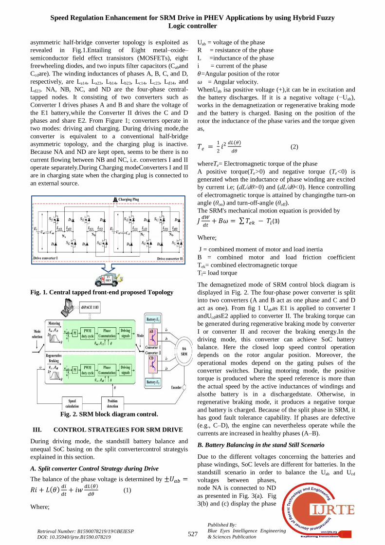
excitation and charging status, respectively. In the picture.
3(b), S0 and S3 perform winding inductance charges.
Fig.3(c) shows the discharging state of excited inductive
winding to the E2 battery. When the E1 battery SoC is lower
than that of the E2, S1, S5, and S6 battery, the winding
inductance charging is switched on. Battery E1 is charged
by switching off devices S1 and S6.
Fig. 3. Balance of battery voltage in working conditions.
(A) Battery voltage equalization. (B) Phase winding
excitation status. (C) E2 charging status.
C. Unequal SoC in a mode of driving
During driving mode, the two batteries are having different
SoC levels as a result of the fluctuating motor parameters
and battery characteristics.The average phase voltage for
phases A and C is expressed in the excitation region.
(4)
(5)
Where
Ua and Uc= phase-A and phase-C voltages
D =duty cycle for the modulation of the
voltage pulse width.
The imbalance between phase A and C i.e. phase A average
voltage is greater than phase C, due to the sharing of same
PWM duty cycle by converter I and II.
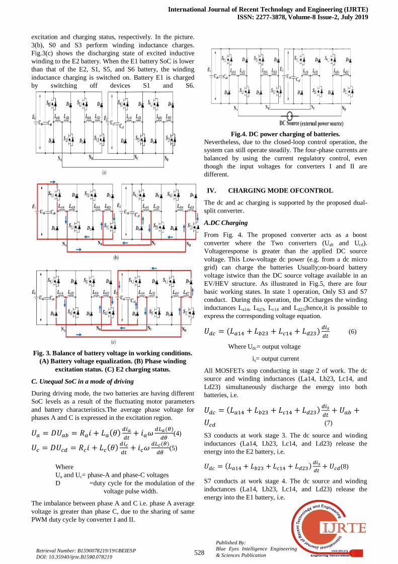
Fig.4. DC power charging of batteries.
Nevertheless, due to the closed-loop control operation, the
system can still operate steadily. The four-phase currents are
balanced by using the current regulatory control, even
though the input voltages for converters I and II are
different.
IV. CHARGING MODE OFCONTROL
The dc and ac charging is supported by the proposed dual-
split converter.
A.DC Charging
From Fig. 4. The proposed converter acts as a boost
converter where the Two converters (Uab and Ucd).
Voltageresponse is greater than the applied DC source
voltage. This Low-voltage dc power (e.g. from a dc micro
grid) can charge the batteries Usually;on-board battery
voltage istwice than the DC source voltage available in an
EV/HEV structure. As illustrated in Fig.5, there are four
basic working states. In state 1 operation, Only S3 and S7
conduct. During this operation, the DCcharges the winding
inductances La14, Lb23, Lc14 and Ld23;hence,it is possible to
express the corresponding voltage equation.
(6)
Where Udc= output voltage
is= output current
All MOSFETs stop conducting in stage 2 of work. The dc
source and winding inductances (La14, Lb23, Lc14, and
Ld23) simultaneously discharge the energy into both
batteries, i.e.
(7)
S3 conducts at work stage 3. The dc source and winding
inductances (La14, Lb23, Lc14, and Ld23) release the
energy into the E2 battery, i.e.
(8)
S7 conducts at work stage 4. The dc source and winding
inductances (La14, Lb23, Lc14, and Ld23) release the
energy into the E1 battery, i.e.
Speed Regulation Enhancement for SRM Drive in PHEV Applications by using Hybrid Fuzzy
Logic controller
529
Published By:
Blue Eyes Intelligence Engineering
& Sciences Publication Retrieval Number: B1590078219/19©BEIESP DOI: 10.35940/ijrte.B1590.078219
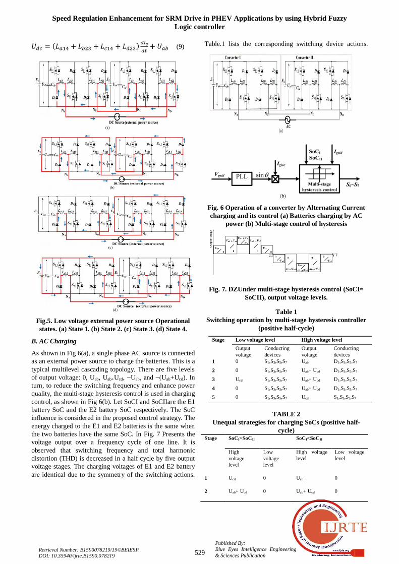
(9)
Fig.5. Low voltage external power source Operational
states. (a) State 1. (b) State 2. (c) State 3. (d) State 4.
B. AC Charging
As shown in Fig 6(a), a single phase AC source is connected
as an external power source to charge the batteries. This is a
typical multilevel cascading topology. There are five levels
of output voltage: 0, Uab, Uab+Ucd, −Uab, and −(Uab+Ucd). In
turn, to reduce the switching frequency and enhance power
quality, the multi-stage hysteresis control is used in charging
control, as shown in Fig 6(b). Let SoCI and SoCIIare the E1
battery SoC and the E2 battery SoC respectively. The SoC
influence is considered in the proposed control strategy. The
energy charged to the E1 and E2 batteries is the same when
the two batteries have the same SoC. In Fig. 7 Presents the
voltage output over a frequency cycle of one line. It is
observed that switching frequency and total harmonic
distortion (THD) is decreased in a half cycle by five output
voltage stages. The charging voltages of E1 and E2 battery
are identical due to the symmetry of the switching actions.
Table.1 lists the corresponding switching device actions.
Fig. 6 Operation of a converter by Alternating Current
charging and its control (a) Batteries charging by AC
power (b) Multi-stage control of hysteresis
Fig. 7. DZUnder multi-stage hysteresis control (SoCI=
SoCII), output voltage levels.
Table 1
Switching operation by multi-stage hysteresis controller
(positive half-cycle)
TABLE 2
Unequal strategies for charging SoCs (positive half-
cycle) Stage SoCI>SoCII SoCI<SoCII
High
voltage
level
Low
voltage
level
High voltage
level
Low voltage
level
1 Ucd 0 Uab 0
2 Uab+ Ucd 0 Uab+ Ucd 0
Stage Low voltage level High voltage level
Output
voltage
Conducting
devices
Output
voltage
Conducting
devices
1 0 S1,S3,S5,S7 Uab D1,S3,S5,S7
2 0 S1,S3,S5,S7 Uab+ Ucd D1,S3,S5,S7
3 Ucd S1,S3,S5,S7 Uab+ Ucd D1,S3,S5,S7
4 0 S1,S3,S5,S7 Uab+ Ucd D1,S3,S5,S7
5 0 S1,S3,S5,S7 Ucd S1,S3,S5,S7

International Journal of Recent Technology and Engineering (IJRTE)
ISSN: 2277-3878, Volume-8 Issue-2, July 2019
530
Published By:
Blue Eyes Intelligence Engineering
& Sciences Publication Retrieval Number: B1590078219/19©BEIESP
DOI: 10.35940/ijrte.B1590.078219
3 Uab+ Ucd Ucd Uab+ Ucd Uab
4 Uab+ Ucd 0 Uab+ Ucd 0
5 Ucd 0 Uab 0
The frequency of switching for the three stages is set by
(10)
(11)
(12)
Whereas,
f1,5= switching frequency for stages 1 and 5
f2,4= switching frequency for stages2 and 4
f3= switching frequency for stage 3
Ugrid = instant grid voltage
H = hysteresis control bandwidth
LABCD= inductance of the circuit, which is the sum of half
inductance (e.g., La14) of phases A, B, C, and D.
The unequal charging strategy for SoC is presented in
Table.2. When SoCUab<SoCUcd, more energy is charged to
the E1 battery than to the II battery. In stages 1–5, the grid
charges the battery E1, while the stages 2–4 charges the
battery E2. If SoCI > SoCII charges the E1 battery less than
the E2 battery. In stages 1–5, the grid charges the battery E2
while the stages 2–4 charges the battery E1.
C. Influence of different phase inductivities
The circuit inductance is required for the design of the
control loop insources, DC and AC charging conditions.
Because of the doubly salient SRM, the inductances of the
phase always vary with the position of the rotor. Luckily,
the sum of the four inductances over the rotor position
becomes much more stable than the phase inductances. It is
therefore used for designing control loops.
V. HYBRID FUZZY CONTROLLER
The main objective of the hybrid controller’s (combination
of PI and fuzzy logic controllers) is to obtain better response
than an individual controller. Two major differences exist
between the conventional PI controller's tracking ability and
the fuzzy logic controller. In steady state,both the PI and the
fuzzy controller produce moderately good tracking.
Nevertheless, a small variation in operation will exhibit
some oscillation in the PI controller due to its fast response,
impact on load. However, under same operating condition
fuzzy controller reduces oscillations even it has a slower
response. Hence a combination of controllers gives quick
response and eliminates associated oscillations in the
system.To justify individual performance switching control
strategy is required. If it requires the advantage of PI
controller fast response, use it for a long time, andit is
necessary to observe that fuzzy controller usage is only the
system under oscillation. Therefore it is necessary to exploit
a methodof switching from PI to the fuzzy controller;it can
be possible by basing on two conditions.
1) Switch on detection of oscillations; 2) Switch on
detection of overshoot. In the Fuzzy Logic controller basing
on IF-THENrules the switching process takes place. IF the
system is activated with an oscillatory behaviourTHEN
fuzzy controller, the PI controller will be operated
otherwise. When the error is zero, the system processed is
considered to have overshot, and the rate of error alters is
any value other than zero. To measure the system,
oscillations the measured and absolute values under the
same period has to be considered. Since the system is
predictable to overshoot during oscillatory behaviour, the
only condition to be considered for switching is
overshooting. In practiceNevertheless, it is more useful to
implement the control signal directly by the controller's
control actions. The fuzzy controller can, therefore, be
designed in such a way that normal behaviour (no
oscillations or over-shooting) leads to a null-fuzzy action.
Consequently, when the fuzzy has a null value, the switch
between the two controllers diminishes the use of PI;
otherwise, the fuzzy output is used.
Fig.8. Switching mechanism structure in a null-fuzzy
action.
VI. MATLAB/SIMULATION RESULTS
Fig.9.Matlab / Simulation Model Battery voltage
equalization with PI
Controller.

Speed Regulation Enhancement for SRM Drive in PHEV Applications by using Hybrid Fuzzy
Logic controller
531
Published By:
Blue Eyes Intelligence Engineering
& Sciences Publication Retrieval Number: B1590078219/19©BEIESP DOI: 10.35940/ijrte.B1590.078219
Fig. 10. Simulation results of IA, Ib, Icand Speed driving
mode.
Fig. 11. Simulation results of Ia, Ib, Ic and speed driving
mode with Braking under normal condition.
Fig. 12. Simulation results in the driving mode of the
phase currents (Ib, Ic) and speed batteries with Braking
under unequal SoC.
Fig. 13. Simulation results in driving mode with Phase
Currents (Ia,Ib,Ic) and Speed Fault-tolerant operation
Fig.14.Model Matlab / Simulation of the different
voltages of the battery
Fig. 15 Response of unequal and equal voltage sources at
Pulse controllers of switches(a) 12 V PWM (E1)−9.6 V.
Fig. 16. Responses of unequal and equal voltage sources,
at Pulse controllers of switches (a) 12V(E1)−10.8 V(E2)
PWM.
Fig. 17. Responses of unequal and equal voltage sources,
at Pulse controllers of switches (a) 12V(E1) −12 V(E2)
PWM
International Journal of Recent Technology and Engineering (IJRTE)
ISSN: 2277-3878, Volume-8 Issue-2, July 2019
532
Published By:
Blue Eyes Intelligence Engineering
& Sciences Publication Retrieval Number: B1590078219/19©BEIESP
DOI: 10.35940/ijrte.B1590.078219
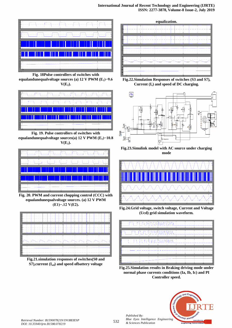
Fig. 18Pulse controllers of switches with
equalandunequalvoltage sources (a) 12 V PWM (E1)−9.6
V(E2).
Fig. 19. Pulse controllers of switches with
equalandunequalvoltage sources(a) 12 V PWM (E1)−10.8
V(E2).
Fig. 20. PWM and current chopping control (CCC) with
equalandunequalvoltage sources. (a) 12 V PWM
(E1)−.12 V(E2).
Fig.21.simulation responses of switches(S0 and
S7),current (Iad) and speed ofbattery voltage
equalization.
Fig.22.Simulation Responses of switches (S3 and S7),
Current (Is) and speed of DC charging.
Fig.23.Simulink model with AC source under charging
mode
Fig.24.Grid voltage, switch voltage, Current and Voltage
(Ucd) grid simulation waveform.
Fig.25.Simulation results in Braking driving mode under
normal phase currents conditions (Ia, Ib, Ic) and PI
Controller speed.
Speed Regulation Enhancement for SRM Drive in PHEV Applications by using Hybrid Fuzzy
Logic controller
533
Published By:
Blue Eyes Intelligence Engineering
& Sciences Publication Retrieval Number: B1590078219/19©BEIESP DOI: 10.35940/ijrte.B1590.078219
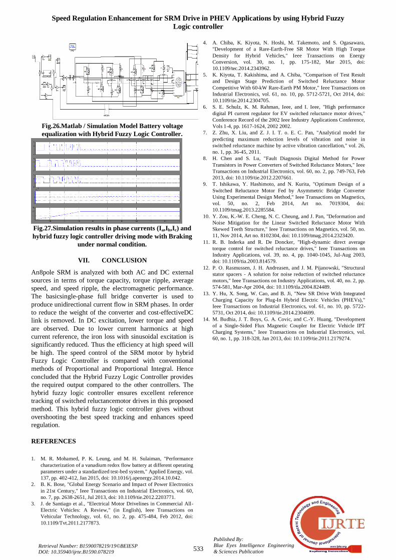
Fig.26.Matlab / Simulation Model Battery voltage
equalization with Hybrid Fuzzy Logic Controller.
Fig.27.Simulation results in phase currents (Ia,Ib,Ic) and
hybrid fuzzy logic controller driving mode with Braking
under normal condition.
VII. CONCLUSION
An8pole SRM is analyzed with both AC and DC external
sources in terms of torque capacity, torque ripple, average
speed, and speed ripple, the electromagnetic performance.
The basicsingle-phase full bridge converter is used to
produce unidirectional current flow in SRM phases. In order
to reduce the weight of the converter and cost-effectiveDC
link is removed. In DC excitation, lower torque and speed
are observed. Due to lower current harmonics at high
current reference, the iron loss with sinusoidal excitation is
significantly reduced. Thus the efficiency at high speed will
be high. The speed control of the SRM motor by hybrid
Fuzzy Logic Controller is compared with conventional
methods of Proportional and Proportional Integral. Hence
concluded that the Hybrid Fuzzy Logic Controller provides
the required output compared to the other controllers. The
hybrid fuzzy logic controller ensures excellent reference
tracking of switched reluctancemotor drives in this proposed
method. This hybrid fuzzy logic controller gives without
overshooting the best speed tracking and enhances speed
regulation.
REFERENCES
1. M. R. Mohamed, P. K. Leung, and M. H. Sulaiman, "Performance
characterization of a vanadium redox flow battery at different operating
parameters under a standardized test-bed system," Applied Energy, vol.
137, pp. 402-412, Jan 2015, doi: 10.1016/j.apenergy.2014.10.042.
2. B. K. Bose, "Global Energy Scenario and Impact of Power Electronics
in 21st Century," Ieee Transactions on Industrial Electronics, vol. 60,
no. 7, pp. 2638-2651, Jul 2013, doi: 10.1109/tie.2012.2203771.
3. J. de Santiago et al., "Electrical Motor Drivelines in Commercial All-
Electric Vehicles: A Review," (in English), Ieee Transactions on
Vehicular Technology, vol. 61, no. 2, pp. 475-484, Feb 2012, doi:
10.1109/Tvt.2011.2177873.
4. A. Chiba, K. Kiyota, N. Hoshi, M. Takemoto, and S. Ogasawara,
"Development of a Rare-Earth-Free SR Motor With High Torque
Density for Hybrid Vehicles," Ieee Transactions on Energy
Conversion, vol. 30, no. 1, pp. 175-182, Mar 2015, doi:
10.1109/tec.2014.2343962.
5. K. Kiyota, T. Kakishima, and A. Chiba, "Comparison of Test Result
and Design Stage Prediction of Switched Reluctance Motor
Competitive With 60-kW Rare-Earth PM Motor," Ieee Transactions on
Industrial Electronics, vol. 61, no. 10, pp. 5712-5721, Oct 2014, doi:
10.1109/tie.2014.2304705.
6. S. E. Schulz, K. M. Rahman, Ieee, and I. Ieee, "High performance
digital PI current regulator for EV switched reluctance motor drives,"
Conference Record of the 2002 Ieee Industry Applications Conference,
Vols 1-4, pp. 1617-1624, 2002 2002.
7. Z. Zhu, X. Liu, and Z. J. I. T. o. E. C. Pan, "Analytical model for
predicting maximum reduction levels of vibration and noise in
switched reluctance machine by active vibration cancellation," vol. 26,
no. 1, pp. 36-45, 2011.
8. H. Chen and S. Lu, "Fault Diagnosis Digital Method for Power
Transistors in Power Converters of Switched Reluctance Motors," Ieee
Transactions on Industrial Electronics, vol. 60, no. 2, pp. 749-763, Feb
2013, doi: 10.1109/tie.2012.2207661.
9. T. Ishikawa, Y. Hashimoto, and N. Kurita, "Optimum Design of a
Switched Reluctance Motor Fed by Asymmetric Bridge Converter
Using Experimental Design Method," Ieee Transactions on Magnetics,
vol. 50, no. 2, Feb 2014, Art no. 7019304, doi:
10.1109/tmag.2013.2285584.
10. Y. Zou, K.-W. E. Cheng, N. C. Cheung, and J. Pan, "Deformation and
Noise Mitigation for the Linear Switched Reluctance Motor With
Skewed Teeth Structure," Ieee Transactions on Magnetics, vol. 50, no.
11, Nov 2014, Art no. 8102304, doi: 10.1109/tmag.2014.2323420.
11. R. B. Inderka and R. De Doncker, "High-dynamic direct average
torque control for switched reluctance drives," Ieee Transactions on
Industry Applications, vol. 39, no. 4, pp. 1040-1045, Jul-Aug 2003,
doi: 10.1109/tia.2003.814579.
12. P. O. Rasmussen, J. H. Andreasen, and J. M. Pijanowski, "Structural
stator spacers - A solution for noise reduction of switched reluctance
motors," Ieee Transactions on Industry Applications, vol. 40, no. 2, pp.
574-581, Mar-Apr 2004, doi: 10.1109/tla.2004.824489.
13. Y. Hu, X. Song, W. Cao, and B. Ji, "New SR Drive With Integrated
Charging Capacity for Plug-In Hybrid Electric Vehicles (PHEVs),"
Ieee Transactions on Industrial Electronics, vol. 61, no. 10, pp. 5722-
5731, Oct 2014, doi: 10.1109/tie.2014.2304699.
14. M. Budhia, J. T. Boys, G. A. Covic, and C.-Y. Huang, "Development
of a Single-Sided Flux Magnetic Coupler for Electric Vehicle IPT
Charging Systems," Ieee Transactions on Industrial Electronics, vol.
60, no. 1, pp. 318-328, Jan 2013, doi: 10.1109/tie.2011.2179274.