Embed Size (px)
Citation preview

International Journal of Fatigue 66 (2014) 138–154
Contents lists available at ScienceDirect
International Journal of Fatigue
journal homepage: www.elsevier .com/locate / i j fa t igue
Ratcheting behaviour of high strength rail steels under bi-axialcompression–torsion loadings: Experiment and simulation
http://dx.doi.org/10.1016/j.ijfatigue.2014.03.0210142-1123/� 2014 Elsevier Ltd. All rights reserved.
⇑ Corresponding author. Tel.: +61 3 990 20113; fax: +61 3 9905 1825.E-mail address: [email protected] (W. Yan).
Chung Lun Pun a, Qianhua Kan b, Peter J. Mutton c, Guozheng Kang b, Wenyi Yan a,⇑a Department of Mechanical and Aerospace Engineering, Monash University, Clayton, VIC 3800, Australiab Department of Applied Mechanics and Engineering, Southwest Jiaotong University, Chengdu 610031, People’s Republic of Chinac Institute of Railway Technology, Monash University, Clayton, VIC 3800, Australia
a r t i c l e i n f o
Article history:Received 9 September 2013Received in revised form 19 March 2014Accepted 21 March 2014Available online 3 April 2014
Keywords:High strength rail steelRatchetingNon-proportional loading pathCyclic loading
a b s t r a c t
Experimental studies were carried out to investigate the ratcheting behaviour of three high strength railsteels of similar nominal hardness but with different chemical compositions subjected to uniaxial andnon-proportionally bi-axial compression–torsion cyclic loading conditions. Different axial stress andequivalent shear stress amplitudes and different non-proportional loading paths were considered. Exper-imental results show that an obvious cyclic softening (i.e., the stress amplitude decreases with theincrease of cyclic number) occurs in all three steels under uniaxial strain cycling. The ratcheting strainand ratcheting strain rate increase with the axial stress and the equivalent shear stress amplitudes underbi-axial compression–torsion stress cycling. Moreover, both ratcheting strain and ratcheting strain rateare strongly influenced by the non-proportional loading path. Among the three rail steels, it is found thatthe low alloy heat-treated rail steel grade has a better resistance to ratcheting than the two hypereutec-toid rail steel grades. The hypereutectoid rail steel grade with a higher carbon content gives a lower rat-cheting strain and a lower ratcheting strain rate than the hypereutectoid rail steel grade with a lowercarbon content under higher loading amplitude. To simulate the ratcheting behaviour of the highstrength rail steels, an existing cyclic plasticity model was modified by coupling a non-proportionallymulti-axial parameter into isotropic softening and kinematic hardening rules. The method to calibratethe material parameters for the plasticity model and the simulated results validated with experimentaldata for the three studied rail steels are presented in the paper. This modified plasticity model with thecalibrated material data from the experimental study can be applied to investigate the ratcheting behav-iour of the three rail steels under wheel–rail cyclic rolling contact in practice.
� 2014 Elsevier Ltd. All rights reserved.
1. Introduction
In an actual wheel–rail rolling contact process, the rail is sub-jected to cyclic loading and the rail surface is subjected to rollingand sliding and relatively high contact stresses. It has been foundthat the cyclic stresses and the plastic deformation are the majorfactors influencing the rail degradation processes [1,2]. The stressesendured by the rail are always multiaxial, non-proportional andrandomly fluctuating in magnitude and direction [3]. If thewheel–rail contact conditions result in a stress level above the plas-tic shakedown limit or ratcheting threshold, new plastic deforma-tion will occur and accumulate, i.e., ratcheting occurs, under eachcycle of loading. Although the plastic deformation in the rail in eachcycle may be very small, the plastic deformation accumulates to
large values over many cycles of loading [4]. When the ratchetingstrain reaches the limiting ductility of the rail, the rail will fail atthe local material point, which corresponds to the initiation of wearor rolling contact fatigue [5–7], e.g., in the form of head checks inthe rail head. This states that plastic ratcheting plays a key role incausing the rolling contact failure of the rail, i.e. wear and rollingcontact fatigue damage. Additionally, the demanding conditionsimposed by rail transport of higher axle loads, higher train speedsand increasing annual haulage rates lead to increasing the rate ofrail degradations and the risk in maintainability and the operationalsafety of the rail. To prevent any catastrophic failure of rail from thedemanding conditions, it is essential to investigate the ratchetingbehaviour and to quantify the cyclic plasticity in the rail head ofthe rails available today. Consequently, the investigation shouldprovide useful information to the development and application ofrail steels and the development of effective rail maintenance strat-egies in order to mitigate rail degradation.

C.L. Pun et al. / International Journal of Fatigue 66 (2014) 138–154 139
Study of ratcheting has been one of the attractive research fieldsin the last three decades. Extensive studies have revealed that thecyclic deformation characteristic of materials subjected to uniaxialand multiaxial cyclic loadings can be demonstrated in strain-controlled loading histories. Under such loading conditions, mate-rials can feature cyclic hardening, cyclic stable or cyclic softening.Stephens et al. [8] stated that the tendency for cyclic softening/hardening of a material is influenced by its microstructure, i.e.the density and arrangement of the dislocation structure andsubstructure of the material. This relationship was also demon-strated in the studies by Sunwoo et al. [9] and Krishna et al. [10].Furthermore, it has been found that the ratcheting behaviour of amaterial is strongly dependent on its cyclic deformation character-istics [11,12].
Under unsymmetrical stress-controlled cyclic loading tests, theinduced hysteresis loops never close and the strain gradually accu-mulates, i.e. strain ratcheting occurs. This is one of the importantplastic deformation phenomena of materials subjected to cyclicloading [13,14] and so the uniaxial and multi-axial stress-con-trolled cyclic loading tests have been widely applied to investigatethe uniaxial and multiaxial ratcheting behaviours of various mate-rials, which include ZK60 Mg alloy [15], 42CrMo steel [16,17],SS304 stainless steel [11,12,18–21], 1020 and 1026 carbon steels[22,23], 1045 steel [24,25], 1070 steel [26,27], 316 stainless steel[28–30] copper and copper alloy [31–33], ordinary and heat-trea-ted rail steels [31,34] and U71Mn rail steel [35,36]. These experi-mental studies revealed that the uniaxial and multiaxialratcheting behaviour of the materials are strongly influenced bythe mean stress, stress amplitude, loading path and loadinghistory.
Although extensive studies have been carried out to investigatethe ratcheting behaviour of different materials, limited ratchetingstudies were conducted on the in-service high strength rail steels[31,34–36]. Bower [31] conducted tension–torsion stress cyclingtests to study the ratcheting behaviour of an ordinary carbon railsteel. McDowell [34] carried out both uniaxial and bi-axial ten-sion–torsion stress cycling tests to investigate the ratcheting behav-iour of an ordinary carbon rail and a heat treated high strength railsteel. Kang et al. [35,36] conducted a systematic experimental pro-gram to investigate the uniaxial and multi-axial ratcheting behav-iour of the U71Mn rail steel. In these reported experiments for railsteels and also other materials, it was found that different materialsexhibit different ratcheting behaviours and varying material charac-teristics. Furthermore, the ratcheting behaviour of the materials inthe reported experimental studies was mostly investigated underuniaxial or tension–torsion multi-axial loadings. In the case of railsteel, the bi-axial cyclic compression–torsion test is one of the mostappropriate methods to simulate the loading experienced by railsteel in the rail head due to rolling contact between the wheel andthe rail. A thorough literature search indicates that the ratchetingbehaviour of the currently-available high strength rail steel gradeshas not been experimentally investigated. The current effort istherefore the first to investigate the ratcheting behaviour of threenew high strength rail steels which are currently used in heavy haulrailways in Australia. The three rail grades selected are of similarnominal hardness, but differ in chemical composition, which en-ables to examine the influence of alloy design on the resistance toratcheting of the rail.
To quantify the ratcheting behaviour in the rail head accurately,a cyclic plasticity constitutive model, which reasonably describesthe ratcheting behaviour, should be applied to simulate the rollingcontact between the wheel and the rail. Extensive studies on cyclicplasticity constitutive models have been conducted for more than30 years. The well-known models, which couple the isotropic andkinematic hardening rules to simulate the ratcheting behaviour, in-clude the Chaboche model [37–39] and the Ohno–Wang model
[40]. The capability of these models for predicting ratcheting wasreviewed by Ohno [41] and Bari and Hassan [42]. One of the majorproblems of these models is the inappropriate prediction of rat-cheting in multiaxial loading cases due to the coupled calculationof plastic modulus with the kinematic hardening rule throughthe consistency condition [42,43]. Bari and Hassan [43] identifiedthat the direction and the magnitude of the normal direction ofthe yield surface translation continuously changes under multiax-ial loading, which is dictated by the kinematic hardening rule,while these remain unchanged throughout the uniaxial loadinghistory. This indicates that an appropriate evolution rule of kine-matic hardening is of paramount importance for accurate multiax-ial ratcheting prediction.
To improve the capability of the model for multiaxial ratchetingprediction, many studies were carried out to modify existing cou-pled models or the kinematic hardening rules. McDowell [34] andJiang and Sehitoglu [44] modified the Ohno–Wang model [40].Voyiadjis and Basuroychowdhury [45] incorporated the stress-ratedirection in the kinematic hardening rule proposed by Chaboche[38]. However, it was found that these modifications cannot im-prove the accuracy of the multiaxial ratcheting prediction [43].AbdelKarim and Ohno [46] combined the nonlinear Armstrongand Frederick kinematic hardening rule [47] and the Ohno andWang rule [40] through a bi-axial parameter with small value. Bariand Hassan [43] superposed the Chaboche model [38] upon theBurlet–Cailletaud model [48] by introducing a new ratchetingparameter. It was demonstrated that the introduction of the bi-ax-ial parameter in the kinematic hardening rule can significantly im-prove the accuracy of multiaxial ratcheting prediction. Döring et al.[49] developed a new kinematic hardening rule which considersthe influence of non-proportional factor on multiaxial ratcheting.Chen et al. [50] also developed a new kinematic hardening modelto describe the non-proportionally multiaxial ratcheting based onthe Ohno–Wang model [40]. Both of these models can reasonablysimulate non-proportionally multiaxial ratcheting. Despite this,all these models have not considered the effects of cyclic harden-ing/softening feature, temperature factors, and time-dependentfactors. Kang et al. [51] extended the Ohno–Wang model to con-sider the influence of strain-amplitude-dependent and non-satu-rated cyclic hardening on uniaxial ratcheting. The AbdelKarimand Ohno model [46] was modified by Kang et al. [52], who intro-duced the temperature-dependent parameters in the kinematichardening rule to consider the effect of dynamic strain aging onuniaxial and multiaxial ratchetting at high temperature. Taguchiand Takahashi [53] developed a constitutive model based onOhno–Wang model [40] to describe the cyclic softening featureof the material and Kan et al. [54] proposed a model to describethe cyclic hardening feature of the material.
Although many cyclic plasticity constitutive models for ratchet-ing simulation have been developed, it is still challenging to find ageneric and precise constitutive model due to the complexity ofratcheting behaviour. Additionally, extensive studies of ratchetinghave demonstrated that different materials exhibit different rat-cheting behaviour and varying material characteristics. This indi-cates that the existing models may not be reasonably andsimultaneously describe the deformation characteristics of thehigh strength rail steels studied herein. Therefore, based on theexperimental results, which will be demonstrated in Section 2 ofthis paper, and in the framework of unified plasticity, a cyclic plas-ticity constitutive model for non-proportionally multiaxial ratchet-ing is developed by modifying the AbdelKarim and Ohno model incurrent study. The cyclic deformation characteristics of the materi-als are taken into account and the influence of non-proportionalityof loading path on multiaxial ratcheting is reflected by introducinga non-proportional factor. Additionally, it has been found that anappropriate method to calibrate the material parameters required

Table 1Chemical composition of the three high strength rail steels.
Rail type C Si Mn P S Cr
HE1 1.0 0.5 0.7 0.2HE2 0.85 0.55 0.55 0.014 0.005LAHT 0.8 0.7 0.95 0.4
0 7 14 21 28 35250
300
350
400
450
500
LAHT HE1 HE2
Har
dnes
s H
V (k
g/m
m2 )
Depth below gauge corner h (mm)
h
0 90 180 270 360300
350
400
450
500
LAHT HE1 HE2Har
dnes
s H
V (k
g/m
m2 )
Angular displacement θ (degree)
0θ
180
(a)
(b)
Fig. 1. Hardness distribution measured in the three rail steels at (a) the depthbelow gauge corner and (b) clockwise angular displacement h from gauge cornerposition of the rail head.
1 For interpretation of colour in Figs. 2 and 4, the reader is referred to the webersion of this article.
140 C.L. Pun et al. / International Journal of Fatigue 66 (2014) 138–154
for the cyclic plasticity constitutive model is important for accuratemultiaxial ratcheting simulation. A detailed methodology of howto calibrate the material parameters of those three studied railsteels required for the developed model are presented. Thedeveloped model with the calibrated material parameters is ap-plied to simulate the uniaxial and multiaxial ratcheting of the stud-ied rail steels and compared to the corresponding experimentalresults.
The structure of this paper is as follows: the details of the mate-rials, specimens and experimental procedures as well as the exper-imental results of monotonic tensile tests, uniaxial strain cyclingand bi-axial compression–torsion stress cycling are presentedand discussed in Section 2. The numerical simulation of the rat-cheting behaviour is presented in Section 3, which includes themodification of an existing cyclic plasticity model, the method tocalibrate the material parameters required by the modified consti-tutive model and the results of the numerical simulation. Conclu-sions are given in Section 4.
2. Experimental study
2.1. Materials and specimens
The materials studied herein are three new high strength pearl-itic rail steels which are currently used in heavy haul railways inAustralia. They are a low alloy heat-treated (LAHT) grade with car-bon content of 0.8% and two hypereutectoid grades with carboncontent respectively of 1% (HE1) and 0.85% (HE2). The chemicalcomposition of these three rail steels is given in Table 1. All thethree rail steels were of similar nominal hardness of 400–420 HVmeasured at the top of the rail head as shown in Fig. 1(a). All thesethree rail steels were also included in a larger range of rail steelssubjected to a detailed program of laboratory and in-service testingby Szablewski et al. [55,56].
Two sets of specimens, round solid specimens and thin-walledtubular standard specimens, were prepared for each material.Monotonic tensile tests and uniaxial strain cycling tests were per-formed on the round solid specimens which have a test sectiondiameter of 5 mm and length of 30 mm while bi-axial compres-sion–torsion tests were performed on the thin-walled tubularspecimen with an outer diameter of 16 mm, an inner diameterof 13 mm, and a length of 30 mm in the test section. The machin-ing process started with extraction of solid bars from the head ofnew 68 kg/m rail samples. The position of the specimen blankswithin the head of the rail took into consideration the gradientin mechanical properties typically present in heat treated grades,as illustrated in Fig. 1(a) and (b), by the hardness distributionmeasured in the current grades. The location of the round solidspecimens and the thin-walled tubular specimens in the cross-section of the rail head, which are illustrated in Fig. 2(a) and(b), respectively, therefore corresponded to a region of relativelyuniform hardness in each of the steels, see Fig. 1(a). In addition,the mean hardness in the region was similar for all three steels,as illustrated in Fig. 1(b) by the hardness distribution measuredin an annulus corresponding to the gauge length of the tubularspecimen. It is worth noting that the definition of angular dis-placement h from the gauge corner of the rail head as shown in
Fig. 1(b) is illustrated by the red1 solid line in Fig. 2(b). The barswere then turned to finalize the specimen’s geometry while thehole in thin-walled tubular specimens was made by the deep holedrilling operation at Metal Drilling Pty Ltd. in Australia before thegeometry was finalized. Specimens were finally polished with afine emery paper. No thermal treatment was performed in thespecimen preparation.
2.2. Experimental program
All tests were conducted at room temperature by employing aservo-valve controlled electro-hydraulic testing machineMTS809-250 kN, which has the capacity to control axial forceand torque independently. An extensometer with an axial strainlimit of ±10% was employed in the monotonic tensile tests andthe uniaxial strain cycling tests while a tension–torsion extensom-eter with 25 mm gauge length and axial strain limit of ±10% andshear angle limit of ±5� was employed in the bi-axial compres-sion–torsion tests to measure the axial elongation and torsionalangle. Loading rates of strain cycling and stress cycling were0.2% s�1 and 200 MPa s�1, respectively. The loading stopped at100 cycles in all cases because a quasi-steady ratcheting rate wasobtained and the coupling between ratcheting and damage couldbe avoided. (Note that the current study focuses on the ratchetingbehaviour only.) In this paper, the axial stress was determined asaxial force per unit cross-section area while the axial force and ax-ial strain were directly obtained from the Teststar II control systemand the extensometer, respectively. The shear stress and the shearstrain were determined respectively from the torque and the tor-sional angle which were measured by the control system.
v

Fig. 2. Location of (a) round solid specimen and (b) thin-walled tubular specimen in the rail head.
C.L. Pun et al. / International Journal of Fatigue 66 (2014) 138–154 141
The initial tests involved monotonic tensile loading condition inorder to obtain some basic mechanical parameters, such as yieldstrength and ultimate tensile strength. Following the monotonictensile test, the basic cyclic deformation characteristics of all thethree materials under symmetrical uniaxial strain cycling was ob-served from the relationship between the stress amplitude ra andthe number of loading cycles N. The stress amplitude was deter-mined as a function of the maximum and minimum of axial stressrmax and rmin in each cycle obtained from the collected experi-mental data. After the symmetrical strain cycling, the ratchetingbehaviour of the materials was studied under bi-axial compres-sion–torsion stress cycling with different axial stress and equiva-lent shear stress amplitudes, see Table 2. Under asymmetricalstress cycling, the maximum and minimum of axial strain emax
and emin and the maximum and minimum of shear strain cmax
and cmin in each cycle were obtained from the collected experi-mental data. Due to the unclosed hysteresis loop produced underasymmetric stress cycling, the axial ratcheting strain er and the tor-sional ratcheting strain cr, can then be determined. Ratchetingstrain rates are then defined as der/dN and dcr/dN, i.e., the incre-ment of ratcheting strains er and cr per cycle. The ratcheting behav-iour of the materials under different loading conditions can beillustrated by the curve of ratcheting strain versus number of load-ing cycles N. To investigate the influence of multi-axial loadingpath on the ratcheting behaviour of the material, five loading pathsas shown in Fig. 3 were adopted, where r and
ffiffiffi3p
s represent theaxial stress and the equivalent shear stress, respectively.
2.3. Results and discussion
2.3.1. Monotonic tensile testsThe tensile stress–strain curves for round solid specimen of all
the three rail steels are shown in Fig. 4. It is worth noting that engi-neering stress and engineering strain are used in current study asthe magnitude of the axial strain is always less than 4% in the cur-rent study. The experimental results of elastic modulus E, nominalyield strength r0.2, ultimate tensile strength rb and elongation atfailure d of all the three rail steels are summarized in Table 3.The results clearly show that the HE2 and the LAHT steels havethe same measured elastic modulus of 212 GPa while the HE1 steelhas a slightly lower elastic modulus of 203 GPa. Fig. 4 demon-strates that the LAHT steel gives the highest ultimate tensilestrength of 1446 MPa while it is 1429 MPa for the HE1 steel and1384 MPa for the HE2 steel. The results also show that the LAHTsteel has a nominal yield strength of 1000 MPa which is 17.5%higher than the HE1 steel and 10.5% higher than the HE2 steel. Un-der the same loading conditions, the HE2 steel has the largest elon-gation of 12%, while it is 11.3% and 8.5% for the LAHT and the HE1steels, respectively. Additionally, the reduction of area, which is theproportional reduction of the cross-sectional area of the specimenmeasured after fracture under the monotonic tensile test, of thethree rail steels is listed in Table 3. The HE2 steel has the largestreduction of area of 39.5% while the reduction of area of the LAHTand the HE1 steels was measured as 35.87% and 14.71%, respec-tively. This indicates that the HE2 steel has the highest ductility

Table 2Loading conditions of biaxial compression–torsion stress cycling tests.
Test Axial stress, r(MPa)
Equivalent shear stressffiffiffi3p
s(MPa)
Loadingpath
1 �400 0 ± 1000 Linear2 �200 0 ± 800 Linear3 �200 0 ± 1000 Linear4 �316.25 ± 316.25 0 ± 800 Oblique5 �200 0 ± 900 Linear6 �100 0 ± 1000 Linear7 0 0 ± 1000 Linear8 �632.5 0 ± 800 Rectangular9 �632.5 0 ± 800 Linear
10 �316.25 ± 316.25 0 ± 800 Butterfly11 0 �100 ± 1000 Linear12 �316.25 ± 316.25 0 ± 800 Elliptical
Fig. 3. Loading paths for compression–torsion stress cycling: (a) linear path, (b)oblique path, (c) rectangular path, (d) butterfly path, and (e) elliptical path.
0 3 6 9 120
300
600
900
1200
1500
Axia
l Stre
ss σ
(MPa
)
Axial Strain ε (%)
LAHT HE1 HE2
Experimental peak stress zone
Fig. 4. Monotonic tensile stress–strain curves of the three rail steels from the roundsolid specimen tests.
142 C.L. Pun et al. / International Journal of Fatigue 66 (2014) 138–154
while the HE1 steel is the least ductile one among all the three railsteels.
According to the study by Szablewski et al. [55], the nominalyield strengths of LAHT and HE2 were 930 MPa and 890 MPa,respectively, which are lower than those found in current study.However, the nominal yield strength of HE1 is 7.1% higher thanin current study. Both of the ultimate tensile strengths of HE1and HE2 were similar in these studies while the ultimate tensilestrength of LAHT in current study is 3% higher than that of Szab-lewski et al. [55]. The elongations at failure of all the three railsteels were found to be similar. The differences in the results
may be due to the differences in specimen position in the rail head.The round solid specimens used in the current study were ex-tracted from the gauge corner of the rail head, centred 18 mm fromthe gage side and 15 mm from the running surface, see Fig. 2(a),while the specimens used by Szablewski et al. [55] were takenfrom a location closer to the surfaces of the rail head, centred12.7 mm from the gage side and 12.7 mm from the running sur-face, in line with the requirements for rail steels suggested bythe American Railway Engineering and Maintenance-of Way Asso-ciation (AREMA) [57].
Carrying out monotonic tensile tests can not only provide somebasic parameters for the materials but also help the design of thebi-axial compression–torsion tests for studying the ratchetingbehaviour. One of the criteria for designing the ratcheting tests isto ensure that the peak stress applied is large enough to cause plas-tic ratcheting. To meet this criterion, the peak stress must be high-er than the yield strength of the material. However, the appliedpeak stress should not be too close to the ultimate tensile strengthin order to avoid unexpected failure of the material in the earlystage of the test. Based on these two criteria and the experimentalresults of all the three materials under monotonic tensile tests, thepeak stress applied in the bi-axial compression–torsion stress cy-cling was selected in the range of 850–1100 MPa as illustrated bythe blue dotted horizontal lines in Fig. 4.
2.3.2. Uniaxial strain cyclingThe round solid specimens of all the three rail steels were tested
under uniaxial symmetrical strain cycling at room temperaturewith a strain amplitude of 0.8%. The cyclic hysteresis stress–strainloops of the three rail steels under uniaxial symmetrical strain cy-cling are shown in Fig. 5. The results clearly show that the size ofthe hysteresis stress–strain loop decreases with the increase inthe number of the loading cycles. Figs. 5(a) and (c) show that thetensile peak stress increases with the number of loading cycleswhile the compressive peak stress decreases. This issue can alsobe clearly identified in Fig. 6 which demonstrates the variation ofthe mean stress rm of all the three materials under uniaxial sym-metrical strain cycling at different number of loading cycles.
The results clearly show that the mean stress values of both theLAHT and the HE2 steels increase with the number of loading cy-cles while the mean stress of the HE1 steel remains almost con-stant. This phenomenon may result from the difference in yieldstrength between these three materials, see Table 3. The HE1 steelhas the lowest yield strength while the LAHT steel has the highestone among all the three rail steels. This indicates that the HE1 steelendures the lowest stress level than the LAHT and the HE2 steelsunder the same strain range. Furthermore, our experimentalresults from uniaxial stress cycling show that all the three
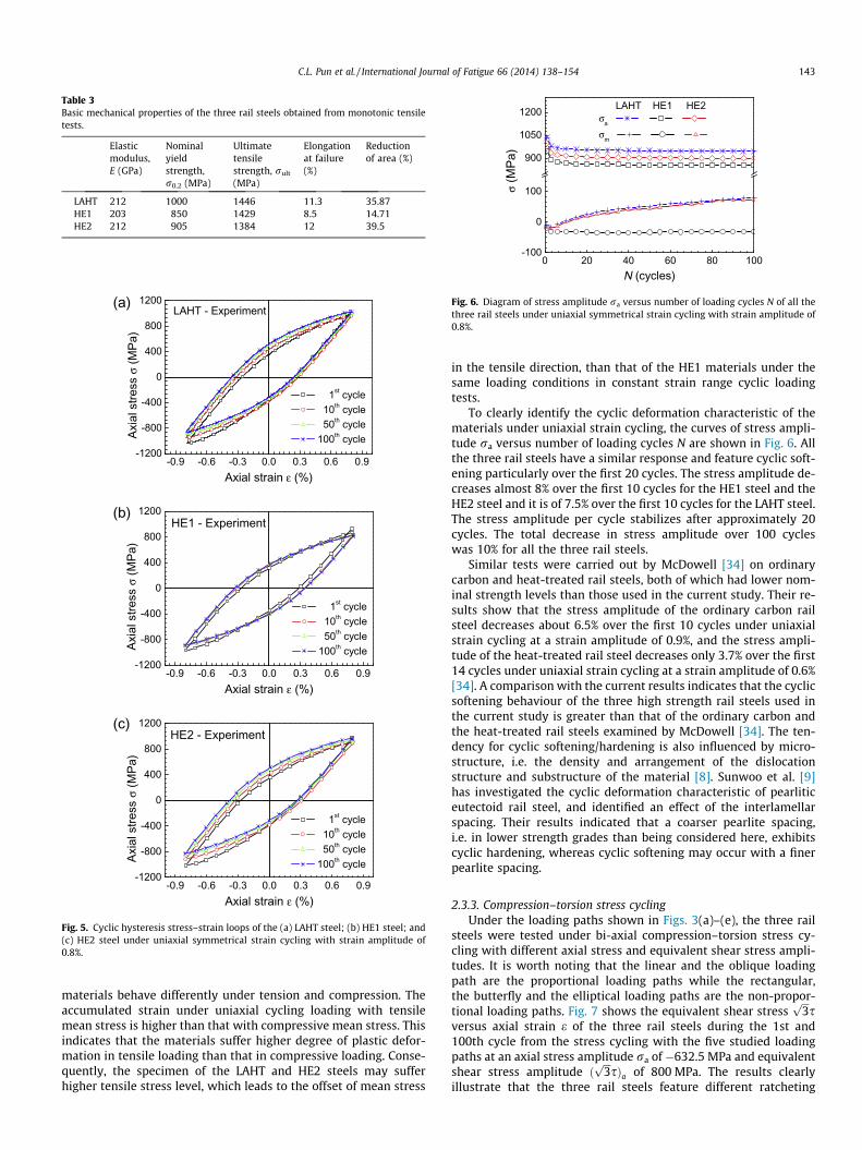
Table 3Basic mechanical properties of the three rail steels obtained from monotonic tensiletests.
Elasticmodulus,E (GPa)
Nominalyieldstrength,r0.2 (MPa)
Ultimatetensilestrength, rult
(MPa)
Elongationat failure(%)
Reductionof area (%)
LAHT 212 1000 1446 11.3 35.87HE1 203 850 1429 8.5 14.71HE2 212 905 1384 12 39.5
-0.9 -0.6 -0.3 0.0 0.3 0.6 0.9-1200
-800
-400
0
400
800
1200
Axia
l stre
ss σ
(MPa
)
Axial strain ε (%)
1st cycle 10th cycle 50th cycle 100th cycle
LAHT - Experiment
-0.9 -0.6 -0.3 0.0 0.3 0.6 0.9-1200
-800
-400
0
400
800
1200
Axia
l stre
ss σ
(MPa
)
Axial strain ε (%)
1st cycle 10th cycle 50th cycle 100th cycle
HE1 - Experiment
(a)
(b)
-0.9 -0.6 -0.3 0.0 0.3 0.6 0.9-1200
-800
-400
0
400
800
1200
Axia
l stre
ss σ
(MPa
)
Axial strain ε (%)
1st cycle 10th cycle 50th cycle 100th cycle
HE2 - Experiment(c)
Fig. 5. Cyclic hysteresis stress–strain loops of the (a) LAHT steel; (b) HE1 steel; and(c) HE2 steel under uniaxial symmetrical strain cycling with strain amplitude of0.8%.
0 20 40 60 80 100-100
0
100
900
1050
1200
σ (M
Pa)
N (cycles)
LAHT HE1 HE2σa
σm
Fig. 6. Diagram of stress amplitude ra versus number of loading cycles N of all thethree rail steels under uniaxial symmetrical strain cycling with strain amplitude of0.8%.
C.L. Pun et al. / International Journal of Fatigue 66 (2014) 138–154 143
materials behave differently under tension and compression. Theaccumulated strain under uniaxial cycling loading with tensilemean stress is higher than that with compressive mean stress. Thisindicates that the materials suffer higher degree of plastic defor-mation in tensile loading than that in compressive loading. Conse-quently, the specimen of the LAHT and HE2 steels may sufferhigher tensile stress level, which leads to the offset of mean stress
in the tensile direction, than that of the HE1 materials under thesame loading conditions in constant strain range cyclic loadingtests.
To clearly identify the cyclic deformation characteristic of thematerials under uniaxial strain cycling, the curves of stress ampli-tude ra versus number of loading cycles N are shown in Fig. 6. Allthe three rail steels have a similar response and feature cyclic soft-ening particularly over the first 20 cycles. The stress amplitude de-creases almost 8% over the first 10 cycles for the HE1 steel and theHE2 steel and it is of 7.5% over the first 10 cycles for the LAHT steel.The stress amplitude per cycle stabilizes after approximately 20cycles. The total decrease in stress amplitude over 100 cycleswas 10% for all the three rail steels.
Similar tests were carried out by McDowell [34] on ordinarycarbon and heat-treated rail steels, both of which had lower nom-inal strength levels than those used in the current study. Their re-sults show that the stress amplitude of the ordinary carbon railsteel decreases about 6.5% over the first 10 cycles under uniaxialstrain cycling at a strain amplitude of 0.9%, and the stress ampli-tude of the heat-treated rail steel decreases only 3.7% over the first14 cycles under uniaxial strain cycling at a strain amplitude of 0.6%[34]. A comparison with the current results indicates that the cyclicsoftening behaviour of the three high strength rail steels used inthe current study is greater than that of the ordinary carbon andthe heat-treated rail steels examined by McDowell [34]. The ten-dency for cyclic softening/hardening is also influenced by micro-structure, i.e. the density and arrangement of the dislocationstructure and substructure of the material [8]. Sunwoo et al. [9]has investigated the cyclic deformation characteristic of pearliticeutectoid rail steel, and identified an effect of the interlamellarspacing. Their results indicated that a coarser pearlite spacing,i.e. in lower strength grades than being considered here, exhibitscyclic hardening, whereas cyclic softening may occur with a finerpearlite spacing.
2.3.3. Compression–torsion stress cyclingUnder the loading paths shown in Figs. 3(a)–(e), the three rail
steels were tested under bi-axial compression–torsion stress cy-cling with different axial stress and equivalent shear stress ampli-tudes. It is worth noting that the linear and the oblique loadingpath are the proportional loading paths while the rectangular,the butterfly and the elliptical loading paths are the non-propor-tional loading paths. Fig. 7 shows the equivalent shear stress
ffiffiffi3p
sversus axial strain e of the three rail steels during the 1st and100th cycle from the stress cycling with the five studied loadingpaths at an axial stress amplitude ra of �632.5 MPa and equivalentshear stress amplitude ð
ffiffiffi3p
sÞa of 800 MPa. The results clearlyillustrate that the three rail steels feature different ratcheting

-3.5 -2.8 -2.1 -1.4 -0.7 0.0
-1000
-500
0
500
1000
1st cyc LAHT HE1 HE2100th cyc LAHT HE1 HE2
31/2
τ (M
Pa)
ε (%)
Loading cycle, N(a)
-3.0 -2.4 -1.8 -1.2 -0.6 0.0
-1000
-500
0
500
1000
1st cyc LAHT HE1 HE2100th cyc LAHT HE1 HE2
31/2
τ (M
Pa)
ε (%)
Loading cycle, N(b)
-3.5 -2.8 -2.1 -1.4 -0.7 0.0
-1000
-500
0
500
1000
1st cyc LAHT HE1 HE2100th cyc LAHT HE1 HE2
31/2
τ (M
Pa)
ε (%)
Loading cycle, N(c)
-3.0 -2.4 -1.8 -1.2 -0.6 0.0
-1000
-500
0
500
1000
1st cyc LAHT HE1 HE2100th cyc LAHT HE1 HE2
31/2
τ (M
Pa)
ε (%)
Loading cycle, N(d)
-2.5 -2.0 -1.5 -1.0 -0.5 0.0
-1000
-500
0
500
1000
1st cyc LAHT HE1 HE2100th cyc LAHT HE1 HE2
31/2
τ (M
Pa)
ε (%)
Loading cycle, N(e)
Fig. 7. Experimental results of equivalent shear stress ðffiffiffi3p
sÞ versus axial strain e of the three studied rail steels during 1st and 100th cycles under (a) linear; (b) oblique; (c)rectangular; (d) butterfly; and (e) elliptical loading paths with the same loading condition of (req)a = 1019.8 MPa.
144 C.L. Pun et al. / International Journal of Fatigue 66 (2014) 138–154
behaviour under the same loading conditions, i.e. the absolute va-lue of ratcheting strain at the 100th cycle for the LAHT steel is thesmallest among all the three rail steels for all the cases. Compari-son of Fig. 7(a)–(e) also indicates that all the three rail steels exhi-bit various ratcheting behaviour under different loading paths. It isworth noting that the axial ratcheting is dominant while the tor-sional ratcheting is relatively small and can be neglected for allthe three rail steels under all the five studied loading paths dueto the non-zero axial mean stress and the symmetrical torsionalstress cycling for all the cases. Fig. 7(a)–(e) shows that the ratchet-ing of all the three rail steels evolves in the mean stress directionunder all the five studied loading paths. Additionally, the hystere-sis loop of all the three rail steels changes from an open loop at the1st cycle to almost a closed loop at the 100th cycle. This impliesthat all the rail steels stabilize after certain number of loadingcycles.
Under the elliptical loading path, the loads are applied 90� out-of-phase. Therefore, the ratio of the torsional stress and the axialstress varies during every single loading cycle. Furthermore, thedirection of the maximum shear stress is changing and slip isoccurring on different planes at different time during every single
loading cycle. This leads to activation of various crystalline slipplanes in the materials and results in additional hardening [8].Consequently, cyclic shift of the hysteresis loops occurred asshown in Fig. 7(e). It was found that the direction of cyclic shiftof the hysteresis loop for the HE1 steel is different from that forthe LAHT and the HE2 steels. This is possibly due to the differencein the chemical composition, see Table 1, and the microstructure ofthe materials.
Figs. 8–10 demonstrate the influence of axial stress amplitudera on the ratcheting behaviour of all the three rail steels underthe linear loading path while the equivalent shear stress amplitudeðffiffiffi3p
sÞa is kept constant as 1000 MPa. The results show that thesame evolution tendency of ratcheting strain and ratcheting strainrate can be found in all the three rail steels. Ratcheting takes placewhen axial stress amplitude ra is high enough. Both axial ratchet-ing strain er and ratcheting strain rate der/dN increase with the ax-ial stress amplitude. Figs. 8 and 9 also demonstrate that the LAHTsteel gives the lowest ratcheting strain and the lowest ratchetingstrain rate when compared to the other two rail steels under thesame loading conditions. In contrast, the HE2 steel has the worstresistance to ratcheting. The ratcheting strain at 100 cycles for

0 20 40 60 80 100-6
-5
-4
-3
-2
-1
0
ε r (%)
N (cycles)
σa
HE1 0 MPa -200 MPa -400 MPaHE2 0 MPa -200 MPa -400 MPaLAHT 0 MPa -200 MPa -400 MPa
Fig. 8. Axial ratchetting strain er versus number of loading cycles N under linearloading path with different axial stress amplitudes ra while the equivalent shearstress amplitude ð
ffiffiffi3p
sÞa is kept constant.
0 20 40 60 80 100-0.6
-0.5
-0.4
-0.3
-0.2
-0.1
0.0
0 2 4 6 8 10
-0.5
-0.4
-0.3
-0.2
-0.1
0.0
d εr /
dN
(%)
N (cycles)
σa
HE1 0 MPa -200 MPa -400 MPaHE2 0 MPa -200 MPa -400 MPaLAHT 0 MPa -200 MPa -400 MPa
Fig. 9. Axial ratchetting strain rate der/dN versus number of loading cycles N underlinear loading path with different axial stress amplitudes ra while the equivalentshear stress amplitude ð
ffiffiffi3p
sÞa is kept constant.
0 20 40 60 80 100-0.15
-0.12
-0.09
-0.06
-0.03
0.00
σa
HE1 0 MPa -200 MPa -400 MPaHE2 0 MPa -200 MPa -400 MPaLAHT 0 MPa -200 MPa -400 MPa
ε a (%
)
N (cycles)
Fig. 10. Axial strain amplitude ea versus number of loading cycles N under linearloading path with different axial stress amplitudes ra while the equivalent shearstress amplitude ð
ffiffiffi3p
sÞa is kept constant.
C.L. Pun et al. / International Journal of Fatigue 66 (2014) 138–154 145
the HE2 steel is up to 55% higher than that found in the LAHT steelunder the same loading conditions. Fig. 10 illustrates the axialstrain amplitude ea of all three rail steels versus number of loadingcycles under the linear loading path with different axial stressamplitude. The results show that the strain amplitudes of thetwo hypereutectoid rail steels, HE1 and HE2 steels, initially de-crease followed by maintaining almost constant values. The sameevolution tendency of strain amplitude is also found for the LAHTwith the axial stress amplitude of �400 MPa, see Fig. 10. For theLAHT steel with the axial stress amplitude of 0 MPa and�200 MPa, the strain amplitude increases in the first few cyclesfollowed by gradually decreases. Additionally, the results showthat the strain amplitudes increase with the axial stress amplitude.
The ratcheting behaviour of the materials also depends on theequivalent shear stress amplitude under linear loading path, asshown in Figs. 11–13. For all the cases, the axial stress amplitudera and the mean equivalent shear stress ð
ffiffiffi3p
sÞm are kept constantas �200 MPa and 0 MPa, respectively. The results indicate thatboth axial ratcheting strain er and axial ratcheting strain rate der/dN increase with the equivalent shear stress amplitude ð
ffiffiffi3p
sÞa,see Figs. 11 and 12. Among all the three rail steels, the LAHT steelhas the best resistance to ratcheting as it has the lowest ratchetingstrain and ratcheting strain rate. When the equivalent shear stressamplitude equals to 1000 MPa, the HE2 steel gives the highest rat-cheting strain which is 55% higher than that for the LAHT steel at100 cycles. When the equivalent shear stress amplitude is lowerthan 1000 MPa, the highest ratcheting strain is contributed bythe HE1 steel. Fig. 13 shows the axial strain amplitude of all thethree rail steels versus number of loading cycles under the linearloading path with different equivalent shear stress amplitudes.The results demonstrate that the strain amplitude increases withthe equivalent shear stress amplitude. Furthermore, the strainamplitude decrease followed by gradual increasing with the load-ing cycle. This indicates that all the three rail steels achieve a stablehysteresis loop after certain number of loading cycles.
The ratcheting behaviour of these three rail steels is signifi-cantly influenced not only by the axial stress and equivalent shearstress amplitudes but also by the non-proportional loading path asillustrated in Figs. 14–16. For all the cases, the applied equivalentstress amplitude (req)a was kept constant as 1019.8 MPa. The re-sults for all the three rail steels show that the non-proportionalloading path influences not only the axial ratcheting strain er butalso the axial ratcheting strain rate der/dN.
Figs. 14(a) and 15(a) show the influence of loading paths on ax-ial ratcheting strain and ratcheting strain rate on the LAHT steel.The results show that the ratcheting strain depends on the loadingpaths. Among all the five loading paths, the elliptical loading pathgives the lowest ratcheting strain and ratcheting strain rate whilethe linear loading path gives the highest ratcheting strain and rate.Fig. 16(a) demonstrates the influence of different loading path onthe strain amplitudes of the LAHT steel. Under the linear and rect-angular loading paths, the material exhibit cyclic hardening in thefirst few cycles and then gradually becomes stable. Under the but-terfly loading path, the rail steel exhibits slightly softeningfollowed by hardening and then it gradually becomes stable. Underthe oblique and elliptical loading paths, the strain amplitudesremain almost constant, which reveals that the material exhibitscyclic stability.
For the HE1 steel, the highest ratcheting strain and rate are con-tributed by the linear loading path as shown in Figs. 14(b) and15(b). The lowest ratcheting strain and rate are relatively difficultto distinguish as the oblique, butterfly and elliptical loading pathsgive similar ratcheting strain when N is smaller than 60. When N islarger than 60, the lowest ratcheting strain is contributed by theoblique and butterfly loading paths. Fig. 16(b) demonstrates thevariation of the strain amplitude of the HE1 steel under differentloading path. The results clearly show that the rail steel exhibitsslightly hardening in the first few cycles under the linear and thebutterfly loading paths while it exhibits slightly softening in thefirst few cycles under the rectangular and oblique paths. Despitethese differences, the material gradually becomes cyclically stable.Under the elliptical path, the material feature cyclic hardening inthe first few cycles and gradually becomes stable. However, thematerial exhibits softening after 40 cycles.
Figs. 14(c) and 15(c) demonstrate the influence of loading pathon the ratcheting strain and the ratcheting strain rate of the HE2steel. In this case, the elliptical loading path gives the lowest rat-cheting strain and the lowest ratcheting strain rate. When N is lessthan 65, the linear loading path gives the highest ratcheting strain.

0 20 40 60 80 100-3.0
-2.4
-1.8
-1.2
-0.6
0.0ε r (%
)
N (cycles)
HE1 1000 MPa 900 MPaHE2 1000 MPa 900 MPaLAHT 1000 MPa 900 MPa
Fig. 11. Axial ratchetting strain er versus number of loading cycles N under linearloading path with different equivalent shear stress amplitudes ð
ffiffiffi3p
sÞa while theaxial stress amplitude is kept constant.
0 20 40 60 80 100-0.25
-0.20
-0.15
-0.10
-0.05
0.00
0 2 4 6 8 10
-0.20
-0.15
-0.10
-0.05
0.00
dεr /
dN (%
)
N (cycles)
HE1 1000 MPa 900 MPaHE2 1000 MPa 900 MPaLAHT 1000 MPa 900 MPa
Fig. 12. Axial ratchetting strain rate der/dN versus number of loading cycles N underlinear loading path with different equivalent shear stress amplitudes ð
ffiffiffi3p
sÞa whilethe axial stress amplitude is kept constant.
0 20 40 60 80 100-0.100
-0.075
-0.050
-0.025
0.000
0.025
HE1 1000 MPa 900 MPaHE2 1000 MPa 900 MPaLAHT 1000 MPa 900 MPa
ε amp (%
)
N (cycles)
Fig. 13. Axial strain amplitude ea versus number of loading cycles N under linearloading path with different equivalent shear stress amplitudes ð
ffiffiffi3p
sÞa while theaxial stress amplitude is kept constant.
0 20 40 60 80 100-2.5
-2.0
-1.5
-1.0
-0.5
0.0LAHT
ε r (%)
N (cycles)
Loading Path: Oblique Rectangular Linear Butterfly Elliptical
(a)
0 20 40 60 80 100-3.5
-2.8
-2.1
-1.4
-0.7
0.0
ε r (%)
N (cycles)
Loading Path: Oblique Rectangular Linear Butterfly Elliptical
HE1(b)
0 20 40 60 80 100-3.5
-2.8
-2.1
-1.4
-0.7
0.0HE2
ε r (%)
N (cycles)
Loading Path: Oblique Rectangular Linear Butterfly Elliptical
(c)
Fig. 14. Axial ratchetting strain er versus number of loading cycles N of the (a) LAHTsteel; (b) HE1 steel; and (c) HE2 steel under different non-proportional loadingpaths while the applied equivalent stress amplitude (req)a is kept constant.
146 C.L. Pun et al. / International Journal of Fatigue 66 (2014) 138–154
When N is larger than 65, the highest ratcheting strain is contrib-uted by the rectangular loading path. Fig. 16(c) illustrates the influ-ence of different loading path on the strain amplitudes of the HE2steel. The results clearly show that the material exhibits cyclic soft-ening in first few cycles and then becomes almost stable under thebutterfly loading path. Under the other four loading paths, thematerial exhibits cyclic hardening in the first few cycles and thenfollowed by cyclically-stable behaviour.
Figs. 17 and 18 show the comparison of the ratcheting strainand the ratcheting strain rate of these three materials under twonon-proportional loading paths, the rectangular and the ellipticalloading paths. Among all the three rail steels, the LAHT steel gives
the lowest ratcheting strain and the lowest ratcheting strain rate.Under the elliptical loading path, the results clearly show thatthe highest ratcheting strain is contributed by the HE1 steel whilethe highest ratcheting strain is contributed by the HE2 steel underthe rectangular loading path. The results also indicate that thematerials sustain a higher ratcheting strain under the rectangularloading path than that under the elliptical loading path with thesame applied equivalent stress amplitude. This is probably due tothe hold of a constant axial and torsional stress in the rectangularloading path [16].
Fig. 19 illustrates the variation of strain amplitudes of the threerail steels under the rectangular and the elliptical loading paths.The results clearly show that the LAHT and the HE2 steel behavesimilarly. Both of them exhibit hardening in the first few cyclesand then gradually becomes stable. For the HE1 steel under therectangular loading path, the strain amplitude initially increasesand then decreases with the increase of the cyclic number whichreveals that the material exhibits softening initially and then fol-lowed by hardening. Under the elliptical loading path, the HE1steel behaves completely different from the LAHT and the HE2

0 20 40 60 80 100-0.75
-0.60
-0.45
-0.30
-0.15
0.00
0.15
-0.60
-0.45
-0.30
-0.15
0.00
LAHTdε
r/ d
N (%
)
N (cycles)
Loading path: Oblique Rectangular Linear Butterfly Elliptical
(a)
0 20 40 60 80 100-0.75
-0.60
-0.45
-0.30
-0.15
0.00
-0.60
-0.45
-0.30
-0.15
0.00
HE1
dεr/ d
N (%
)
N (cycles)
Loading path: Oblique Rectangular Linear Butterfly Elliptical
(b)
0 20 40 60 80 100-0.75
-0.60
-0.45
-0.30
-0.15
0.00
0 2 4 6 8 10
0 2 4 6 8 10
0 2 4 6 8 10-0.75
-0.60
-0.45
-0.30
-0.15
0.00
HE2
dεr/ d
N (%
)
N (cycles)
Loading path: Oblique Rectangular Linear Butterfly Elliptical
(c)
Fig. 15. Axial ratchetting strain rate der/dN versus number of loading cycles N of the(a) LAHT steel; (b) HE1 steel; and (c) HE2 steel under different non-proportionalloading paths while the applied equivalent stress amplitude (req)a is kept constant.
0 20 40 60 80 100-0.60
-0.45
-0.30
-0.15
0.00
0.15
Loading Path: Linear Oblique Rectangular Butterfly Elliptical
ε a (%
)
N (cycles)
LAHT
0 20 40 60 80 100-0.60
-0.45
-0.30
-0.15
0.00
Loading Path: Linear Oblique Rectangular Butterfly Elliptical
ε a (%
)
N (cycles)
HE1
(a)
(b)
0 20 40 60 80 100-0.60
-0.45
-0.30
-0.15
0.00
Loading Path: Linear Oblique Rectangular Butterfly Elliptical
ε a (%
)
N (cycles)
HE2(c)
Fig. 16. Axial strain amplitude ea versus number of loading cycles N of the (a) LAHTsteel; (b) HE1 steel; and (c) HE2 steel under different non-proportional loadingpaths while the applied equivalent stress amplitude (req)a is kept constant.
C.L. Pun et al. / International Journal of Fatigue 66 (2014) 138–154 147
steel. The HE1 steel exhibits hardening in the first 40 cycles andthen softens. This can explain why the shape of the elliptic hyster-esis loop of the HE1 steel is different from that of the LAHT and theHE2 steels as shown in Fig. 7(e). Stephens et al. [8] identified thatthe initially hard or hardened materials tend to soften easier undercyclic loading due to the greater dislocation mobility. Among allthe three studied rail steels, the HE1 steel has the highest carboncontent of 1% and is the hardest one, and had the highest tendencyto exhibit softening under cyclic loading.
The strain amplitudes of the three rail steels at different cyclicnumber under different loading paths are illustrated in Figs. 16and 19. It was found that the materials exhibit cyclic softening orcyclic hardening in the first few cycles and then gradually becomesstable in most of the cases. These phenomena may result from theresidual work hardening during the manufacturing process of therail steels. As mentioned above, the accumulated strain varies withthe loading paths. When the accumulated strain is small, the resid-ual work hardening cannot be overcome initially and is released bysubsequent cycling which leads to cyclic softening. For instance,the HE2 steel subjected to butterfly loading paths gives the lowestratcheting strain in the first few cycles among all the five studiedloading paths, see Fig. 16(c) and it was found that the material
exhibits obvious cyclic softening in the first few cycles and thenbecomes stable quickly. In contrast, the residual work hardeningcan be overcome when the accumulated strain is high enoughand the materials exhibit cyclic hardening. Similar ratchetingbehaviour was also investigated for the U71Mn rail steel by Kanget al. [35] under uniaxial strain cycling with different strainamplitudes.
Figs. 8, 9, 11, 12, 14 and 15 demonstrate that the axial ratchet-ing strain increases but its rate decreases continuously withincreasing number of loading cycles. After a certain number ofloading cycles, a quasi-steady ratcheting rate is obtained, i.e., theaxial ratcheting strain rate becomes very small and remains almostconstant in the remaining cycles. It is also found that the increaseof axial stress and equivalent shear stress leads to an increase inthe required cyclic number to reach quasi-steady ratcheting rateof the material. Besides, the required cyclic number to reach qua-si-steady of different material is found to be different, i.e. 20 cyclesfor the LAHT steel in Fig. 15(a), 45 cycles for the HE1 steel inFig. 15(b) and 37 cycles for the HE2 steel in Fig. 15(c) under ellip-tical path. This indicates that the required number of loading cyclefor reaching quasi-steady ratcheting rate also depends on the

0 20 40 60 80 100-4.0
-3.2
-2.4
-1.6
-0.8
0.0ε r (%
)
N (cycles)
Loading Path:HE1 Rectangular EllipticalHE2 Rectangular EllipticalLAHT Rectangular Elliptical
Fig. 17. Comparison of the ratchetting strain er of all the three rail steels under therectangular path and elliptical path while the applied equivalent stress amplitude(req)a is kept constant.
0 20 40 60 80 100
-0.45
-0.30
-0.15
0.00
0 2 4 6 8 10
-0.45
-0.30
-0.15
0.00
dεr/ d
N (%
)
N (cycles)
Loading path:HE1 Rectangular EllipticalHE2 Rectangular EllipticalLAHT Rectangular Elliptical
Fig. 18. Comparison of the ratchetting strain rate der/dN of all the three rail steelsunder the rectangular path and elliptical path while the applied equivalent stressamplitude (req)a is kept constant.
0 20 40 60 80 100-0.5
-0.4
-0.3
-0.2
-0.1
Loading Path:HE1 Rectangular EllipticalHE2 Rectangular EllipticalLAHT Rectangular Elliptical
ε a (%
)
N (cycles)
Fig. 19. Comparison of the strain amplitude ea of all the three rail steels under therectangular path and elliptical path while the applied equivalent stress amplitude(req)a is kept constant.
850 900 950 1000 1050-5
-4
-3
-2
-1
0
ε r (%)
(σeq)a (MPa)
HE1 HE2 LAHT
Fig. 20. Comparison of the ratchetting strain er of all the three rail steels under thelinear loading path with different equivalent stress amplitude (req)a.
850 900 950 1000 1050
-0.016
-0.012
-0.008
-0.004
0.000
d εr/d
N (%
)
(σeq)a (MPa)
HE1 HE2 LAHT
Fig. 21. Comparison of the ratchetting strain rate der/dN of all the three rail steelsunder the linear loading path with different equivalent stress amplitude (req)a.
148 C.L. Pun et al. / International Journal of Fatigue 66 (2014) 138–154
material properties. Referring to the experimental results ofmonotonic tensile tests presented in Section 2.3.1, it is found thatthe material which gives a higher yield strength requires a largercyclic number to reach quasi-steady ratcheting rate.
Through the comparison of all the three rail steels underbi-axial compressive–torsion stress cycling with different axialstress and equivalent shear stress amplitudes as well as differentmulti-axial loading paths, it is found that the LAHT steel alwaysgives the lowest ratcheting strain and the lowest ratcheting strainrate, see Figs. 8, 9, 11, 12, 17, 18, 20 and 21. This indicates that thelow alloy heat-treated rail steel grade has a better resistance to
ratcheting than that of the hypereutectoid rail steel grades. Figs. 20and 21 demonstrate the comparison of the ratcheting strain er andthe ratcheting strain rate der/dN at 100th loading cycle of all thethree rail steels under the linear loading path with different ap-plied equivalent stress amplitude (req)a. Among the two hypereu-tectoid rail steel grades, the HE1 steel with carbon content of 1%gives a lower ratcheting strain and a lower ratcheting strain ratethan the HE2 steel with carbon content of 0.85% if the appliedequivalent stress amplitude is high enough, i.e. when the appliedequivalent stress amplitude is larger than 930 MPa, and vice versaat a lower equivalent stress amplitude, see Figs. 20 and 21. Thiscomparison indicates that an increase of carbon content in thehypereutectoid rail steel grade can reduce the ratcheting straindevelopment when the rail subjected to severe loading conditions,e.g. in heavy haul operations.
Although biaxial tension–torsion tests were traditionally per-formed to investigate the ratcheting behaviour of materials, the re-sults in the current study show that material ratcheting also takesplace under compression–torsion cyclic loading. The latter loadingcondition is also closer to that which occurs under normal wheel–rail contact. In the current study, the ratcheting strain rate undermulti-axial stress cycling rapidly decreases with an increasednumber of cycles, which is different from existing cyclic softeningmaterials [16]. The normal and shear stresses responses in numer-ical simulation of wheel–rail contact patch was found to be ellipti-cal in shape which implies that the relative weak ratchetingbehaviour will occur in real wheel/rail rolling contact process.These features and their effect on ratcheting should be taken intoaccount in cyclic constitutive model development in the future.

C.L. Pun et al. / International Journal of Fatigue 66 (2014) 138–154 149
Research on ratcheting-fatigue life interaction indicates that thepresence of ratcheting not only decreases the fatigue life of mate-rials but also influences the fatigue crack growth due to accumu-lated plastic strain [16,21,58–61]. The fatigue life of materialsstrongly depends on the mean stress and the stress amplitude un-der uniaxial cyclic loading and it depends on the axial stress andthe equivalent shear stress amplitudes and the multi-axial loadingpath under multi-axial cycling loading. Moreover, the interactionbehaviour between the ratcheting and the fatigue life of the mate-rial was found to be different for different materials. The currentstudy does not investigate the interaction between the ratchetingand the fatigue life of the materials (i.e. the tests were not per-formed till failure of the materials) as the aim of the study is toinvestigate and compare the ratcheting behaviour of all the threehigh strength rail steels under multi-axial cyclic loading. Despitethis, it is worth noting that the occurrence of the ratcheting straindoes not enhance the fatigue life of the rail steels.
3. Numerical simulation
3.1. A modified cyclic plasticity model for ratcheting
The forementioned experimental results show that there aresome similar ratcheting features of the three rail steels under uni-axial strain cycling and biaxial stress cycling. To numerically pre-dict the ratcheting performance of the rail steels in practice, it isessential to apply an appropriate and reliable constitutive modelto simulate the cyclic deformation behaviour of the rail steels.Based on the initial isotropic elasticity and associated plastic flowrules at small deformation, the main equations adopted in cyclicplastic constitutive modelling are as follow,
e ¼ ep þ ee ð1Þ
ee ¼ D�1 : r ð2Þ
_ep ¼ffiffiffi32
r_k
s� aks� ak ð3Þ
Fy ¼ffiffiffiffiffiffiffiffiffiffiffiffiffiffiffiffiffiffiffiffiffiffiffiffiffiffiffiffiffiffiffiffiffiffiffiffiffiffiffiffiffi1:5ðs� aÞ : ðs� aÞ
p� Q ð4Þ
where e, ee, ep and _ep are total strain, elastic strain, plastic strainand plastic strain rate, respectively. D is the fourth order tensorof elasticity. s and a are the deviatoric parts of stress and backstress. Q is the isotropic deformation resistance and Fy is thevon-Mises yield function. _k is the rate of plastic multiplier. k k de-notes the norm.
AbdelKarim and Ohno [46] proposed a kinematic hardening rulewhich combines the Armstrong and Frederick [47] and the Ohnoand Wang [40] rules, and was adopted in the current study. Theevolution equations of back stress for the kinematic hardening ruleis shown as follows,
a ¼XM
i¼1
ai ði ¼ 1;2; . . . ;MÞ ð5Þ
_ai ¼ fi23
ri _ep � liai _p� HðfiÞai _ep :ai
kaik� li _p
� �� �ð6Þ
where ai is components of back stress a, H is Heaviside function, h iis Macaulay’s bracket and means that: as x 6 0, hxi = 0; as x > 0,hxi = x. _p is the effective plastic strain rate. The critical state of dy-namic recovery is described by the critical surfaces fi:
fi ¼ kaik2 � r2i ¼ 0 ð7Þ
The ratcheting parameter li is assumed as a constant for differ-ent components of back stress.
li ¼ l ¼ l0ð1� aUÞ ð8Þ
where l0 is a ratcheting parameter in the uniaxial cases. a is a mate-rial parameter reflecting the influence of the non-proportional load-ing paths on ratcheting behaviour.
As discussed in Section 2, the experimental results have shownthat the non-proportionally bi-axial ratcheting behaviour of all thethree rail steels strongly depends on the loading paths. Therefore, itis important to consider the non-proportionality of loading path inthe cyclic plasticity model. In order to improve the cyclic plasticitymodel to simulate the non-proportional ratcheting responses, thenon-proportional parameter U in Eq. (8), initially proposed by Ta-naka [62] is implemented into the modified model.
The Tanaka non-proportional parameter has been successfullyimplemented into some existing constitutive models for the simu-lation of biaxial cyclic deformation of several materials. Jiang andKurath [63] modified the Tanaka model [62] to simulate the non-proportional cyclic deformation of the 304 stainless steel and the1045 steel. Their numerical results showed that the inclusion ofthe Tanaka non-proportional parameter can significantly improvethe accuracy of the simulation of non-proportional cyclic loadings.Similar studies were also carried out by Hassan et al. [64] andKrishna et al. [10] who implemented the Tanaka non-proportionalparameter into a modified Chaboche model to improve the biaxialratcheting simulation. Zhang and Jiang [65] developed a constitu-tive model by following the Armstrong–Frederick hardening rulewith the Tanaka non-proportional parameter. Their results indi-cated that non-proportional hardening of the pure polycrystallinecopper can be captured successfully. Additionally, Krishna et al.[10] investigated that the Tanaka non-proportional parameter ismore effective than the Benallal and Marquis [66] parameter inimproving the simulation of both ratcheting and evolution ten-dency of ratcheting.
In current study, the non-proportional parameter U is modifiedin the model through a fourth order tensor C,
_C ¼ bðn� n� CÞ _p ð9aÞ
U ¼
ffiffiffiffiffiffiffiffiffiffiffiffiffiffiffiffiffiffiffiffiffiffiffiffiffiffiffiffiffiffiffiffiffiffiffiffiffiffiffiffiffiffiffiffiffiffiffiffiffiffiffiffiffiffiffiffiffi2
trðC : CÞ � n : C : C : ntrðC : CÞ
� �sð9bÞ
where n ¼ _ep
k _epk, b is the rate parameter of the dislocation evolution.tr(�) is the trace of a tensor. The tensor C describes the slow growthof the internal dislocation structure induced by the plastic deforma-tion process, its components equal to zero for an initially isotropicmaterial and reach the target value n � n that depends on the plas-tic strain direction of the loading. Therefore, the non-proportionalfactor U is associated with the non-proportional loading path andhistory. For proportional uniaxial loadings, U = 0; for a non-propor-tional circular path, U � 1; for the other non-proportional multi-ax-ial loading paths, their non-proportional factor satisfies 0 < U < 1. Itis worth noting that the original non-proportional parameter U pro-posed by Tanaka [62] approaches 1=
ffiffiffi2p
for a non-proportional cir-cular path.
Basically, the cyclic softening rule adopted in the cyclic plastic-ity model is used with the combined hardening model which con-siders both isotropic and kinematic hardening rules to capture thecyclic softening feature and the ratcheting behaviour. In order toconsider the effects of loading history and non-proportional load-ing path, the following evolution equations for the isotropic defor-mation resistance Q are adopted in the constitutive model,
_Q ¼ cðQ sa � QÞ _p ð10aÞ
0.0 0.5 1.0 1.5 2.0600
800
1000
1200
1400
εpiAx
ial s
tress
σ (M
Pa)
Plastic strain εp (%)
σi
i = 1, 2, 3....10 LAHT
Fig. 22. Uniaxial stress r versus plastic strain ep from the monotonic loading test ofthe LAHT rail steel for calibrating the back stress of the cyclic plasticity model.
Table 4Calibrated material parameters used in the modified plasticity model for the three railsteels.
HE1 HE2 LAHT
f1, f2, f3, f4 1820, 926, 498,331
900, 389, 174, 90 1470, 3110, 1350,556
f5, f6, f7, f8 188, 110, 77.5,30.6
55.2, 41.3, 34.1,24.4
286, 112, 80, 35.6
r1, r2, r3, r4
(MPa)24.1, 83.6, 68.9,62
109, 102, 62.4,55.1
177, 23.1, 44.9,53.3
r5, r6, r7, r8
(MPa)66.9, 59.1, 31.2,440
56.5, 69.1, 44.8,194
56.2, 47.4, 35.3,344
E (GPa), v, l0 203, 0.33, 0.05 212, 0.33, 0.01 212, 0.33, 0.045Q0, Qsa0, Qsa1
(MPa)650, 400, 440 680, 550, 660 630, 460, 600
a, c, c 0.7, 50, 2.0 0.7, 50, 1.0 0.7, 50, 2.0
0.0 0.6 1.2 1.8 2.4 3.00
300
600
900
1200
1500
Exp. Simu. LAHT HE1 HE2
Axia
l Stre
ss σ
(MPa
)
Axial Strain ε (%)
Fig. 23. Comparison between the experimental and simulated results of the stress–strain response under monotonic tensile test for the three rail steels.
-0.9 -0.6 -0.3 0.0 0.3 0.6 0.9-1200
-800
-400
0
400
800
1200
1st cycle 10th cycle 50th cycle 100th cycle
Axia
l stre
ss σ
(MPa
)
Axial strain ε (%)
LAHT - Simulation
-0.9 -0.6 -0.3 0.0 0.3 0.6 0.9-1200
-800
-400
0
400
800
1200
Axia
l stre
ss σ
(MPa
)Axial strain ε (%)
1st cycle 10th cycle 50th cycle 100th cycle
HE1 - Simulation
-0.9 -0.6 -0.3 0.0 0.3 0.6 0.9-1200
-800
-400
0
400
800
1200Ax
ial s
tress
σ (M
Pa)
Axial strain ε (%)
1st cycle 10th cycle 50th cycle 100th cycle
HE2 - Simulation
(a)
(b)
(c)
Fig. 24. Simulated cyclic stress–strain hysteresis loops of the (a) LAHT steel; (b)HE1 steel; and (c) HE2 steel under uniaxial symmetrical strain cycling with strainamplitude of 0.8%.
150 C.L. Pun et al. / International Journal of Fatigue 66 (2014) 138–154
Q saðUÞ ¼ U½Q sa1 � Q sa0� þ Q sa0 ð10bÞ
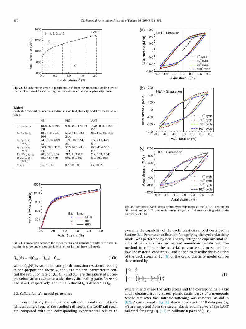
where Qsa(U) is saturated isotropic deformation resistance relatingto non-proportional factor U, and c is a material parameter to con-trol the evolution rate of Qsa. Qsa0 and Qsa1 are the saturated isotro-pic deformation resistance under the cyclic loading paths for U = 0and U � 1, respectively. The initial value of Q is denoted as Q0.
3.2. Calibration of material parameters
In current study, the simulated results of uniaxial and multi-ax-ial ratcheting of one of the studied rail steels, the LAHT rail steel,are compared with the corresponding experimental results to
examine the capability of the cyclic plasticity model described inSection 3.1. Parameter calibration for applying the cyclic plasticitymodel was performed by non-linearly fitting the experimental re-sults of uniaxial strain cycling and monotonic tensile test. Themethod to calibrate the material parameters is presented be-low.The material constants fi and ri used to describe the evolutionof the back stress in Eq. (6) of the cyclic plasticity model can bedetermined by,
fi ¼ 1ep
i
ri ¼ ri�ri�1ep
i�ep
i�1� riþ1�ri
epiþ1�ep
i
� �ep
i
8><>: ð11Þ
where ri and epi are the yield stress and the corresponding plastic
strain obtained from a stress–plastic strain curve of a monotonictensile test after the isotropic softening was removed, as did in[67]. As an example, Fig. 22 shows how a set of 10 data pair (ri,ep
i ) are extracted from the stress–plastic strain curve of the LAHTrail steel for using Eq. (11) to calibrate 8 pairs of (fi, ri).

-3.5 -2.8 -2.1 -1.4 -0.7 0.0
-1000
-500
0
500
1000
1st cyc LAHT HE1 HE2100th cyc LAHT HE1 HE2
31/2
τ (M
Pa)
ε (%)
Loading cycle, NSimulation
-3.0 -2.4 -1.8 -1.2 -0.6 0.0
-1000
-500
0
500
1000
1st cyc LAHT HE1 HE2100th cyc LAHT HE1 HE2
31/2
τ (M
Pa)
ε (%)
Loading cycle, NSimulation
-3.5 -2.8 -2.1 -1.4 -0.7 0.0
-1000
-500
0
500
1000
1st cyc LAHT HE1 HE2100th cyc LAHT HE1 HE2
31/2
τ (M
Pa)
ε (%)
Loading cycle, NSimulation
(a) (b)
(c)
-3.0 -2.4 -1.8 -1.2 -0.6 0.0
-1000
-500
0
500
1000
1st cyc LAHT HE1 HE2100th cyc LAHT HE1 HE2
31/2
τ (M
Pa)
ε (%)
Loading cycle, NSimulation(d)
-2.5 -2.0 -1.5 -1.0 -0.5 0.0
-1000
-500
0
500
1000
1st cyc LAHT HE1 HE2100th cyc LAHT HE1 HE2
31/2
τ (M
Pa)
ε (%)
Loading cycle, NSimulation(e)
Fig. 25. Simulated results of equivalent shear stressffiffiffi3p
s versus axial strain e of the three rail steels under (a) linear path; (b) oblique path; (c) rectangular path; (d) butterflypath; and (e) elliptical path.
C.L. Pun et al. / International Journal of Fatigue 66 (2014) 138–154 151
The control parameter c is assumed to be a constant for uniaxialand bi-axial loadings and can be obtained by fitting the curve of theequivalent stress amplitude req
a versus the number of cycles N bythe following equation:
reqa ¼ A1 þ A2½1� expð�cNÞ� ð12Þ
where A1, A2 are fitting parameters. When the material reaches cyc-lic saturation at a certain accumulated plastic strain, the saturatedisotropic deformation resistances of Qsa0 can be calculated by
Q sa0 ¼ Q 0 � ðreqa jN¼1 � A1 � A2Þ ð13Þ
where reqa jN¼1 is the equivalent stress amplitude at first cycle. Qsa1
can be obtained by trial–error method from the bi-axial stress cy-cling due to lack of the experimental data of the bi-axial symmetri-cal strain cycling. The ratcheting parameters, l0 reflecting thekinematic hardening in the uniaxial case, can be determined byan optimizing process, i.e.:
dðl0Þ ¼Xn
k¼1
eexpr � esimu
r
eexpr
k
ð14Þ
where eexpr and esimu
r are experimental and simulated ratchetingstrains at a certain cycle (i.e., 100th cycle in the present study),
respectively. k is the number of uniaxial loading cases. The param-eter l0 can be obtained from the minimum value of d(l0). Theparameter a, which reflects the influence of non-proportional load-ing path on the parameter l shown in Eq. (8), is assumed as a con-stant for all non-proportional loading paths and can be obtainedfrom fitting an arbitrary non-proportional path. The parameter brepresents the rate of dislocation evolution, which affects the firstfew cycles and reaches rapidly a stable value at a certain non-pro-portional loading path. Therefore, it is assumed as a constant andcan be optimized from different non-proportional loading paths,similar to Eq. (14) for calibrating l0. It is noted that the parameterl0 has almost no influence on uniaxial tensile and strain cycling re-sults and should be determined first. Finally, the material parame-ters obtained for all the three rail steels are summarized in Table 4.
3.3. Simulations of uniaxial strain cyclic loading
With the material parameters listed in Table 4, the applicabilityof the cyclic plasticity model as described in Section 3.1 was firstverified by simulating the monotonic tensile tests. The simulatedstress–strain responses of all the three rail steels are shown inFig. 23, which agree well with the corresponding experimental

0 20 40 60 80 100
-3.5
-2.8
-2.1
-1.4
-0.7
0.0
Exp. Simu. Linear Oblique Rectangular Butterfly Elliptical
ε r (%)
N (cycles)
LAHT
0 20 40 60 80 100-4.5
-3.6
-2.7
-1.8
-0.9
0.0
Exp. Simu. Linear Oblique Rectangular Butterfly Elliptical
ε r (%)
N (cycles)
HE1
(a)
(b)
0 20 40 60 80 100-4.5
-3.6
-2.7
-1.8
-0.9
0.0
Exp. Simu. Linear Oblique Rectangular Butterfly Elliptical
ε r (%)
N (cycles)
HE2(c)
Fig. 26. Experimental and simulated ratchetting strain by the proposed modelunder biaxial cyclic loadings for the (a) LAHT steel; (b) HE1 steel; and (c) HE2 steel.
152 C.L. Pun et al. / International Journal of Fatigue 66 (2014) 138–154
results. After that, the uniaxial strain cycling of the three rail steelswas simulated numerically. Figs. 5 and 24 show the experimentaland simulated stress–strain curves of the three rail steels underuniaxial strain cycling, respectively. The results show that the sim-ulated results agree with the experimental results fairly well forthe values of the stress in valleys although there are some differ-ences in the shapes of hysteresis loops. Furthermore, the stressamplitudes obtained from the simulated results are in reasonableagreement with the experiments. It is worth noting that the cyclicsoftening behaviours of the materials, i.e. stress amplitude ra de-creases with the increase of loading cycles, has been successfullycaptured by the simulations.
3.4. Simulations of bi-axial stress cyclic loading
The modified cyclic plasticity model with the calibrated mate-rial data was applied to simulate the bi-axial stress cycling withdifferent non-proportional loading paths. The simulated axialstrain-torsional stress curves under the five studied loading pathsof all the three rail steels are shown in Fig. 25 and compared withthe corresponding experimental results shown in Fig. 7. The resultsshow that the simulated hysteresis loops are similar to the exper-imental ones. Additionally, the predicted axial ratcheting strain er
at different number of loading cycles from all different loadingpaths is presented in Fig. 26 and compared with correspondingexperimental results.
Fig. 26(a) shows the comparison for the LAHT steel and it indi-cates that the ratcheting strain is slightly over predicted in the caseof the oblique loading path. Despite this, the overall simulated re-sults are in a reasonable agreement with the experiment and theshapes of the hysteresis loops are similar. For the butterfly loadingpath, the evolution tendency of ratcheting can be captured by themodified cyclic plasticity model fairly well although the axial rat-cheting strain is underpredicted slightly. For the other three load-ing paths, the comparison shows that the simulations agree wellwith the corresponding experimental results.
Comparisons between the numerical results and the experi-mental results for the HE1 steel are shown in Fig. 26(b). Thenumerical results demonstrate that the evolution tendency of theratcheting strain is not simulated well in the case of the rectangu-lar loading path. Despite this, the ratcheting strain value at 100thcycle is similar to the experimental results. For the linear loadingpath, the overall simulated results give a reasonable agreementwith the experimental results although slight overprediction ofthe ratcheting strain is found. The results also illustrate that themodel can give a reasonable prediction of ratcheting strain valuein the case of the butterfly path though slight underprediction isfound at the start of the simulation. For the oblique and the ellip-tical paths, the comparison shows that the simulations agree wellwith the corresponding experimental results.
Fig. 26(c) illustrates the comparisons for the HE2 steel. The re-sults show that the ratcheting behaviour of this rail steel underbutterfly path cannot be simulated as well as the other two railsteels. The value of the ratcheting strain is underpredicted about30%. Despite this, the overall simulated results of the HE2 steel un-der other four loading paths give a reasonable agreement with theexperimental results. The ratcheting strain is slightly overpre-dicted for the linear loading path while the ratcheting strain isslightly underpredicted for the elliptical loading path. For the obli-que and the rectangular loading paths, the comparison shows thatthe simulations agree well with the corresponding experimentalresults for the values of the axial ratcheting strain.
The predicted axial strain amplitude ea at different number ofloading cycles from all the different loading paths are presentedin Fig. 27 and compared with corresponding experimental results.Fig. 27(a) illustrates the comparisons for the LAHT steel. The
comparison clearly demonstrates that the simulated evolution ten-dency and strain amplitude values for the linear loading path agreewell with the experimental results. For the oblique and the rectan-gular loading paths, the strain amplitude is overestimated. Thesimulated results for the butterfly and the elliptical paths give areasonable agreement with the experimental results althoughslight differences are found in the first few cycles. Fig. 27(b) dem-onstrates the comparisons of the axial strain amplitude betweenthe numerical results and the experimental results. The resultsshow that the simulation for the linear loading agrees well withthe experimental results. The evolution tendency and the valuesof axial strain amplitude for the other cannot be simulated well,especially for the elliptical path. The decrease of strain amplitudeafter 40th cycle cannot be captured in the simulation. Despite this,the ratio of overprediction or underprediction of strain amplitudesfor the other three loading paths is small and acceptable. Fig. 27(c)shows the comparison for the HE2 steel. The comparison show thatthe simulation for the linear loading path agrees well with the cor-responding experimental results for the values of axial strainamplitude although slight overprediction is found in the first few

0 20 40 60 80 100-0.60
-0.45
-0.30
-0.15
0.00
Exp. Simu. Linear Oblique Rectangular Butterfly Elliptical
ε a (%)
N (cycles)
LAHT
0 20 40 60 80 100
-0.60
-0.45
-0.30
-0.15
0.00
Exp. Simu. Linear Oblique Rectangular Butterfly Elliptical
ε a (%)
N (cycles)
HE1
(a)
(b)
0 20 40 60 80 100
-0.60
-0.45
-0.30
-0.15
0.00
Exp. Simu. Linear Oblique Rectangular Butterfly Elliptical
ε a (%)
N (cycles)
HE2(c)
Fig. 27. Experimental and simulated strain amplitude by the proposed model underbiaxial cyclic loadings for the (a) LAHT steel; (b) HE1 steel; and (c) HE2 steel.
C.L. Pun et al. / International Journal of Fatigue 66 (2014) 138–154 153
cycles. For the oblique loading path, the evolution tendency agreeswell with the experimental results but the values of strain ampli-tude are slightly underpredicted. For the rectangular loading path,the simulated results agree fairly well with the experimental re-sults. For the butterfly and the elliptical loading paths, differencesare found in the first few cycles. Despite this, the overall simulatedresults give a reasonable agreement with the experimental results.
Although discrepancies can be found in the prediction of the ax-ial ratcheting strain and axial strain amplitudes, especially for theHE1 steel, as shown in Figs. 26 and 27, the overall simulated resultsof the ratcheting strain values for all three rail steels are in a rea-sonable agreement with the experiment as the ratio of overpredic-tion or underprediction is small for most cases, i.e. less than 10%.This is due to the introduction of the non-proportionally multi-ax-ial parameter U into the isotropic and kinematic hardening rules.Additionally, the evolution tendency of ratcheting can be capturedby the modified cyclic plasticity model fairly well and the shapes ofthe hysteresis loops are similar to the experimental results, seeFigs. 25 and 26. This indicates that the modified cyclic plasticitymodel can be applied to quantify ratcheting strain of these hyper-eutectoid rail steels under bi-axial cyclic loadings with acceptable
accuracy. The suggested method of calibrating the material param-eters from the experimental study can also be applied to calibratethe material parameters of other rail steels. Furthermore, this cyc-lic plasticity model with the calibrated material data from theexperimental study can be applied to simulate actual wheel–railrolling contact to investigate ratcheting performance of differentrail steel in practice in our future work.
4. Conclusions
Three high strength, heat treated rail steels, a low alloy heat-treated (LAHT) rail steel grade and two hypereutectoid rail steelgrades with different carbon contents (HE1 steel for the higher car-bon content rail steel and HE2 steel for the lower carbon contentrail steel), which are currently used in heavy haul operations inAustralia, have been tested under uniaxial strain cycling and bi-ax-ial compression–torsion cyclic loading conditions. Under uniaxialsymmetrical strain cycling, all the three materials exhibit cyclicsoftening at the start and then stabilize quickly as the stress ampli-tude of all three materials decreases almost 8% over the first 10 cy-cles for the HE1 steel and the HE2 steel and it is of 7.5% over thefirst 10 cycles for the LAHT steel before reaching a stable value.
Under multi-axial stress cycling, the ratcheting behaviour ofthese materials is significantly influenced by the axial stress andthe equivalent shear stress amplitudes and the non-proportionalloading path. Both ratcheting strain and ratcheting strain rate in-crease with axial stress and equivalent shear stress amplitudes. Aquasi-steady ratcheting rate reaches after a certain number ofloading cycles. This quasi-steady number of loading cycles is influ-enced by axial stress and equivalent shear stress amplitudes aswell as material’s yield strength. Among all the five studied loadingpaths, the elliptical loading path, which is more relevant to wheel/rail contact situations, gives the lowest ratcheting strain and thelowest ratcheting strain rate. Comparing all the three rail steels,it has been found that the low alloy heat-treated rail steel gradehas the best resistance to ratcheting. Among the two hypereutec-toid rail steel grades, the one with a higher percentage of carboncontent gives a lower ratcheting strain and ratcheting strain rateif the rail is subjected to a higher equivalent stress amplitude,e.g. in heavy haul operations. Besides, the ratcheting strain rate un-der multi-axial stress cycling rapidly decreases with an increasednumber of cycles, which is different from existing cyclic softeningmaterials.
A modified cyclic plasticity model was applied to simulate theratcheting behaviour of the rail steels under experimental loadingconditions. The method for calibrating the material parameters re-quired by the modified model is presented and the materialparameters for all the three studied rail steels were determinedfrom the experimental data. The comparison between the simu-lated results and the experimental data show that the modifiedcyclic plasticity model has the capacity to simulate both uniaxialand biaxial ratcheting behaviour of the studied rail steels with anacceptable accuracy. It provides the confidence for the future workto apply this constitutive model to study the actual wheel/railrolling contact in practice.
Acknowledgement
The present work has been partly funded by an Australian Re-search Council Linkage Project (LP110100655) with support fromRio Tinto Iron Ore.
References
[1] Cannon DF, Edel D-O, Grassie SL, Sawley K. Rail defects: an overview. FatigueFract Eng Mater Struct 2003;26:865–87.

154 C.L. Pun et al. / International Journal of Fatigue 66 (2014) 138–154
[2] Wen Z, Wu L, Li W, Jin X, Zhu M. Three-dimensional elastic–plastic stressanalysis of wheel–rail rolling contact. Wear 2011;271:426–36.
[3] Olver AV. The mechanism of rolling contact fatigue: an update. Proc IMechEPart J: J Eng Tribol 2005;219:313–30.
[4] Kapoor A. Wear by plastic ratchetting. Wear 1997;212:119–30.[5] Kapoor A. A re-evaluation of the life to rupture of ductile metals by cyclic
plastic strain. Fatigue Fract Eng Mater Struct 1994;17:201–19.[6] Tyfour WR, Beynon JH, Kapoor A. Deterioration of rolling contact fatigue life of
pearlitic rail due to dry-wet rolling–sliding line contact. Wear1996;197:255–65.
[7] Su X, Clayton P. Ratchetting strain experiments with a pearlitic steel underrolling/sliding contact. Wear 1997;205:137–43.
[8] Stephens RI, Fatemi A, Stephens RR, Fuchs HO. Metal fatigue in engineering.2nd ed. New York: John Wiley and Sons; 2001.
[9] Sunwoo H, Fine ME, Meshii M, Stone DH. Cyclic deformation of pearliticeutectoid rail steel. Metall Trans A 1982;13A:2035–47.
[10] Krishna S, Hassan T, Naceur IB, Saï K, Cailletaud G. Macro versus micro-scaleconstitutive models in simulating proportional and non-proportional cyclicand ratcheting responses of stainless steel 304. Int J Plast 2009;25:1910–49.
[11] Hassan T, Kyriakides S. Ratcheting of cyclically hardening and softeningmaterials: I. Uniaxial behavior. Int J Plast 1994;10(2):149–84.
[12] Hassan T, Kyriakides S. Ratcheting of cyclically hardening and softeningmaterials: II. Multiaxial behavior. Int J Plast 1994;10(2):185–212.
[13] Jiang Y, Zhang J. Benchmark experiments and characteristic cyclic plasticitydeformation. Int J Plast 2008;24:1481–515.
[14] Taleb L. About the cyclic accumulation of the inelastic strain observed inmetals subjected to cyclic stress control. Int J Plast 2013;43:1–19.
[15] Xiong Y, Yu Q, Jiang Y. An experimental study of cyclic plastic deformation ofextruded ZK60 magnesium alloy under uniaxial loading at room temperature.Int J Plast 2013;53:107–24.
[16] Kang G, Liu Y, Ding J. Multiaxial ratchetting–fatigue interactions of annealedand tempered 42CrMo steels: experimental observations. Int J Fatigue2008;30:2104–18.
[17] Kang G, Liu Y, Ding J, Gao Q. Uniaxial ratcheting and fatigue failure of tempered42CrMo steel: damage evolution and damage-coupled visco-plasticconstitutive model. Int J Plast 2009;25:838–60.
[18] Kang G, Gao Q, Cai L, Sun Y. Experimental study on uniaxial andnonproportionally multiaxial ratcheting of SS304 stainless steel at room andhigh temperatures. Nucl Eng Des 2002;216:13–26.
[19] Kang G, Gao Q, Yang X. Uniaxial and non-proportionally multiaxial ratchetingof SS304 stainless steel at room temperature: experiments and simulations.Int J Non-linear Mech 2004;39:843–57.
[20] Kang G, Kan Q, Zhang J, Sun Y. Time-dependent ratchetting experiments ofSS304 stainless steel. Int J Plast 2006;22:858–94.
[21] Kang G, Liu Y, Li Z. Experimental study on ratchetting–fatigue interaction ofSS304 stainless steel in uniaxial cyclic stressing. Mater Sci Eng A 2006;435–436:396–404.
[22] Hassan T, Kyriakides S. Ratcheting of cyclic plasticity, part I. Uniaxial behavior.Int J Plast 1992;8:91–116.
[23] Hassan T, Kyriakides S. Ratcheting of cyclic plasticity, part II. Multiaxialbehavior. Int J Plast 1992;8:117–46.
[24] Jiang Y. An experimental study of inhomogeneous cyclic plastic deformation. JEng Mater Technol 2001;123:274–80.
[25] Zhang J, Jiang Y. An experimental study of inhomogeneous cyclic plasticdeformation of 1045 steel under multiaxial cyclic loading. In J Plast2005;21:2174–90.
[26] Jiang Y, Huseyin S. Cyclic ratcheting of 1070 steel under multiaxial stressstates. Int J Plast 1994;10:608–79.
[27] Jiang Y, Huseyin S. Multiaxial cyclic ratcheting under multiple step loading. IntJ Plast 1994;10:849–70.
[28] Portier L, Calloch S, Marquis D, Geyer P. Ratcheting under tension–torsionloadings: experiments and modelling. Int J Plast 2000;16:303–35.
[29] Kang GZ, Gao Q, Cai LX, Yang XJ, Sun Y. Experimental study on uniaxial andmultiaxial strain cyclic characteristics and ratcheting of 316L stainless steel. JMater Sci Technol 2001;17(2):219–23.
[30] Date S, Ishikawa H, Otani T, Takahashi Y. Effect of ratcheting deformation onfatigue and creep-fatigue life of 316FR stainless steel. Nucl Eng Des2008;238:336–46.
[31] Bower AF. Cyclic hardening properties of hard-drawn copper and rail steel. JMech Phys Solids 1989;37(4):455–70.
[32] Lim CB, Kim KS, Seong JB. Ratcheting and fatigue behaviour of a copper alloyunder uniaxial cyclic loading with mean stress. Int J Fatigue 2009;31:501–7.
[33] Kim CY, Song JH, Hwangbo Y, Shim HS. Plastic deformation behavior of Cu thinfilms during fatigue testing. Procedia Eng 2010;2:1421–30.
[34] McDowell DL. Stress state dependence of cyclic ratcheting behaviour of tworail steels. Int J Plast 1995;11(4):397–421.
[35] Kang GZ, Gao Q, Yang XJ. Experimental study on the cyclic deformation andplastic flow of U71Mn rail steel. Int J Mech Sci 2002;44:1647–63.
[36] Kang GZ, Gao Q. Uniaxial and non-proportionally multiaxial ratcheting ofU71Mn rail steel: experiments and simulations. Mech Mater 2002;34:809–20.
[37] Chaboche JL. Time-independent constitutive theories for cyclic plasticity. Int JPlast 1986;2:149–88.
[38] Chaboche JL. On some modifications of kinematic hardening to improve thedescription of ratcheting effects. Int J Plast 1991;7:661–78.
[39] Chaboche JL. Modeling of ratchetting: evaluation of various approaches. Eur JMech A/Solids 1994;13:501–18.
[40] Ohno N, Wang J-D. Kinematic hardening rules with critical state of dynamicrecovery, part I: formulations and basic features for ratcheting behaviour. Int JPlast 1993;9:375–90.
[41] Ohno N. Recent progress in constitutive modelling for ratchetting. Mater SciRes Int 1997;3(1):1–9.
[42] Bari S, Hassan T. Anatomy of coupled constitutive models for ratchetingsimulation. Int J Plast 2000;16:381–409.
[43] Bari S, Hassan T. An advancement in cyclic plasticity modelling for multiaxialratcheting simulation. Int J Plast 2002;18:873–94.
[44] Jiang Y, Sehitoglu H. Modeling of cyclic ratchetting plasticity, Part I:development of constitutive relations. ASME J Appl Mech 1996;63:720–5.
[45] Voyiadjis GZ, Basuroychowdhury IN. A plasticity model for multiaxial cyclicloading and ratchetting. Acta Mech 1998;126:19–35.
[46] AbdelKarim M, Ohno N. Kinematic hardening model suitable for ratchetingwith steady-state. Int J Plast 2000;16:225–40.
[47] Armstrong PJ, Frederick CO. A mathematical representation of the multiaxialBauschinger effect. CEGB report RD/B/N731, Berkely Nuclear Laboratories,Berkely, UK; 1966.
[48] Burlet H, Cailletaud G. Numerical techniques for cyclic plasticity at variabletemperature. Eng Comput 1986;3:143–53.
[49] Döring R, Hoffmeyer J, Seeger T, Vormwald M. A plasticity model forcalculating stress–strain sequences under multiaxial nonproportional cyclicloading. Comput Mater Sci 2003;28:587–96.
[50] Chen X, Jiao R, Kim KS. On the Ohno–Wang kinematic hardening rules formultiaxial ratcheting modelling of medium carbon steel. Int J Plast2005;21:161–84.
[51] Kang GZ, Ohno N, Nebu A. Constitutive modelling of strain-range-dependentcyclic hardening. Int J Plast 2003;19:1801–19.
[52] Kang GZ, Li YG, Gao Q. Non-proportionally multiaxial ratcheting of cyclichardening materials at elevated temperatures: experiments and simulations.Mech Mater 2005;37:1101–18.
[53] Yaguchi M, Takahashi Y. Ratcheting of viscoplastic material with cyclicsoftening, part 2: application of constitutive models. Int J Plast2005;21:835–60.
[54] Kan QH, Kang GZ, Zhang J. A unified visco-plastic constitutive model foruniaxial time-dependent ratchetting and its finite element implementation.Theor Appl Fract Mech 2007;47:133–44.
[55] Szablewski D, Kalay S, LoPresti J. Development and evaluation of highperformance rail steels for heavy haul operations. In: Proceedings of the2011 international heavy haul association conference, Calgary, Canada, 19–22June; 2011.
[56] Szablewski D, Gutscher D, LoPresti J, Kalay S. Effect of heavy axle loads onsuper premium rail steels and rail joining methods. In: Proceedings of the 10thinternational heavy haul association conference, New Delhi, India, 4–6February; 2013. p. 43–50.
[57] The American Railway Engineering and Maintenance-of-Way Association(AREMA). Manual for railway engineering, vol. 1. AREMA; 2012 [chapter 4].
[58] Rider RJ, Harvey SJ, Chandler HD. Fatigue and ratcheting interactions. Int JFatigue 1995;17(7):507–11.
[59] Xia Z, Kujawski D, Ellyin F. Effect of mean stress and ratcheting strain onfatigue life of steel. Int J Fatigue 1996;18(5):335–41.
[60] Yang X. Low cycle fatigue and cyclic stress ratcheting failure behaviour ofcarbon steel 45 under uniaxial cyclic loading. Int J Fatigue 2005;27:1124–32.
[61] Tong J, Zhao LG, Lin B. Ratcheting strain as a driving force for fatigue crackgrowth. Int J Fatigue 2013;46:49–57.
[62] Tanaka E. A nonproportionality parameter and a cyclic viscoplasitcconstitutive model taking into account amplitude dependences and memoryeffects of isotropic hardening. Eur J Mech A/Solids 1994;13:155–73.
[63] Jiang Y, Kurath P. Nonoproportional cyclic deformation: critical experimentsand analytical modelling. Int J Plast 1997;13(8–9):743–63.
[64] Hassan T, Taleb L, Krishna S. Influence of non-proportional loading onratcheting responses and simulations by two recent cyclic plasticity models.Int J Plast 2008;24:1863–89.
[65] Zang J, Jiang Y. Constitutive modelling of cyclic plasticity deformation of a purepolycrystalline copper. Int J Plast 2008;24:1890–915.
[66] Benallal A, Marquis D. Constitutive equations for nonproportional cyclicelasto-viscoplasticity. ASME J Eng Mater Technol 1987;109:326–36.
[67] Kang GZ, Gao Q, Yang XJ. A viscoplastic constitutive model incorporated withcyclic hardening for uniaxial/multiaxial ratcheting of SS304 stainless steel atroom temperature. Mech Mater 2002;34:521–31.