Embed Size (px)
Citation preview

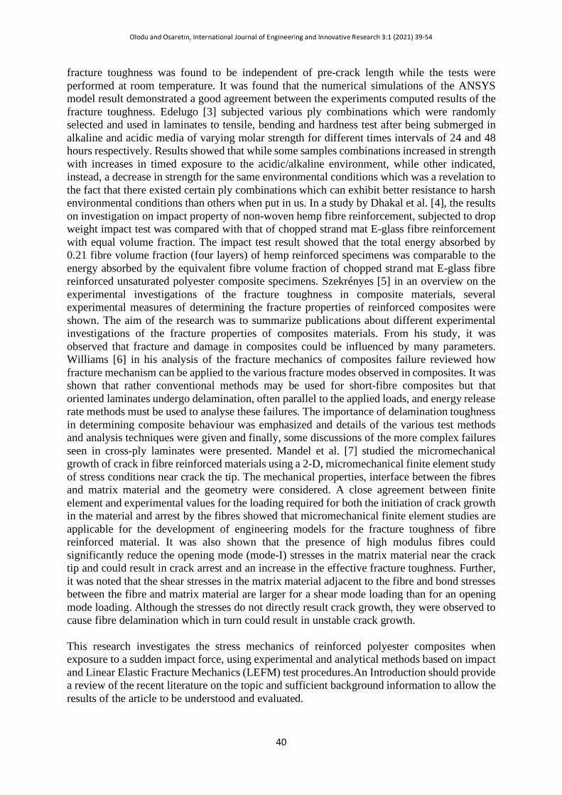
International Journal of Engineering and Innovative Research 3:1 (2021) 39-54
International Journal of Engineering and Innovative
Research
http://dergipark.gov.tr/ijeir
39
STRESS MECHANICS OF REINFORCED POLYESTER COMPOSITES
Osaretın M.O 1 , Olodu D.D 1* 1 Benson Idahosa University, Faculty of Engineering, Department of Mechanical Engineering, PMB 1100,
Benin City, Edo State, Nigeria.
*Sorumlu Yazar: [email protected]
https://doi.org/10.47933/ijeir.772055
(Received: 20.08.2020; Accepted: 19.09.2020)
ABSTRACT: This research investigates the stress mechanics of reinforced polyester composites when exposure to a sudden impact force, using experimental and analytical methods based on impact and Linear Elastic Fracture Mechanics (LEFM) test procedures. In this study, the stress distribution around crack tip and zone for 14 test samples with geometry 210 mm x 150 mm were investigated. KII stress intensity factors, critical stress, σC, shear stress, τnt the impact energy, E and impact strength, U were determined for each specimen. The mode I fracture toughness, KIC was found to be to be 4.97 MPa.m1/2 at a critical stress of 13.53 MPa while the mode II fracture toughness, KIIC was 1.31 MPa.m1/2 at a shear stress, τnt of 3.71 MPa. The effective thickness was found to be in the range of 80-100mm at fibre volume fraction, Vf of within 0.35-0.50. This was largely found to be as result of fibre bridging and crack arrest mechanisms. This mechanism prevented crack growth direction in specimens containing woven roving not to propagate along the original direction, but change the direction to an inclined path till failure with the exception of those containing soft and hard mat in which the crack grew in the original crack direction as the stress intensity increased. During the impact test, fibre stacking sequence played a vital role, thereby making specimens containing woven roving to resist impact damage and failure, and this resulted in fibre pull-out during fracture. The stress could be seen to concentrated at the crack tip and around the loading pins on a smaller level, compared to the level at the crack tip. Keywords: Analytical Methods, Critical Stress, Reinforced Polyester Composites, Shear Stress 1. INTRODUCTION
In the analysis of impact damage and fracture of composites, the review of the sources, nature and curvature of impactor and how these fracture initiation takes place, propagate from a microstructural scale at the sites of flaws, and how the coalescence of these flaws leads to a visible separation process that manifests on a macrostructural level before resulting in a catastrophic failure are vital. According to Làszló and George [1], the mechanical and thermal behaviours of a structure depend on the properties of the fibres and the matrix and on the amount and orientations of the fibres. In the structural analysis of composites, the design steps from the micromechanics (which takes into account the fibre and matrix properties) through macromechanics (which treats the properties of the composite) are taken into consideration. Radif and Ali [2] in their studies of the fracture toughness of kenaf mat reinforced polyester composite estimated and analysed the crack criteria by using the mathematical laws that were limited in E1820 standard and the results affirmed by applying the numerical solution of ANSYS to estimate the fracture toughness value , besides the energy release rate of biomass composite. The fracture characterisation of the composites was carried out using the compact tension (CT) specimen that was common used to determine the mode-I fracture properties. The
Olodu and Osaretin, International Journal of Engineering and Innovative Research 3:1 (2021) 39-54
40
fracture toughness was found to be independent of pre-crack length while the tests were performed at room temperature. It was found that the numerical simulations of the ANSYS model result demonstrated a good agreement between the experiments computed results of the fracture toughness. Edelugo [3] subjected various ply combinations which were randomly selected and used in laminates to tensile, bending and hardness test after being submerged in alkaline and acidic media of varying molar strength for different times intervals of 24 and 48 hours respectively. Results showed that while some samples combinations increased in strength with increases in timed exposure to the acidic/alkaline environment, while other indicated, instead, a decrease in strength for the same environmental conditions which was a revelation to the fact that there existed certain ply combinations which can exhibit better resistance to harsh environmental conditions than others when put in us. In a study by Dhakal et al. [4], the results on investigation on impact property of non-woven hemp fibre reinforcement, subjected to drop weight impact test was compared with that of chopped strand mat E-glass fibre reinforcement with equal volume fraction. The impact test result showed that the total energy absorbed by 0.21 fibre volume fraction (four layers) of hemp reinforced specimens was comparable to the energy absorbed by the equivalent fibre volume fraction of chopped strand mat E-glass fibre reinforced unsaturated polyester composite specimens. Szekrényes [5] in an overview on the experimental investigations of the fracture toughness in composite materials, several experimental measures of determining the fracture properties of reinforced composites were shown. The aim of the research was to summarize publications about different experimental investigations of the fracture properties of composites materials. From his study, it was observed that fracture and damage in composites could be influenced by many parameters. Williams [6] in his analysis of the fracture mechanics of composites failure reviewed how fracture mechanism can be applied to the various fracture modes observed in composites. It was shown that rather conventional methods may be used for short-fibre composites but that oriented laminates undergo delamination, often parallel to the applied loads, and energy release rate methods must be used to analyse these failures. The importance of delamination toughness in determining composite behaviour was emphasized and details of the various test methods and analysis techniques were given and finally, some discussions of the more complex failures seen in cross-ply laminates were presented. Mandel et al. [7] studied the micromechanical growth of crack in fibre reinforced materials using a 2-D, micromechanical finite element study of stress conditions near crack the tip. The mechanical properties, interface between the fibres and matrix material and the geometry were considered. A close agreement between finite element and experimental values for the loading required for both the initiation of crack growth in the material and arrest by the fibres showed that micromechanical finite element studies are applicable for the development of engineering models for the fracture toughness of fibre reinforced material. It was also shown that the presence of high modulus fibres could significantly reduce the opening mode (mode-I) stresses in the matrix material near the crack tip and could result in crack arrest and an increase in the effective fracture toughness. Further, it was noted that the shear stresses in the matrix material adjacent to the fibre and bond stresses between the fibre and matrix material are larger for a shear mode loading than for an opening mode loading. Although the stresses do not directly result crack growth, they were observed to cause fibre delamination which in turn could result in unstable crack growth. This research investigates the stress mechanics of reinforced polyester composites when exposure to a sudden impact force, using experimental and analytical methods based on impact and Linear Elastic Fracture Mechanics (LEFM) test procedures.An Introduction should provide a review of the recent literature on the topic and sufficient background information to allow the results of the article to be understood and evaluated.
Olodu and Osaretin, International Journal of Engineering and Innovative Research 3:1 (2021) 39-54
41
2. MATERIALS AND METHODS
2.1. Materials This research is carried out on samples fabricated by randomly varying plies of reinforcements in form of woven roving, hard and soft E-glass fibre mats, combined in unsaturated polyester resin (specific gravity 1.12, viscosity of 65cps and gel time of 25 min) matrix. The catalyst and accelerator used were methyl ethyl ketone peroxide (MEKP) and cobalt respectively due to their compatibility in polyester as curing agents at ambient temperature condition. 2.2. Methods Impact damage in metal is easily detected as damage starts at the impacted surface; however, damage in composites often begins on the non-impacted surface or in the form of an internal delamination which is immediately preceded by matrix cracking on the impacted surface. The behaviour of fibre reinforced composites when suddenly impacted by a solid object was the subject of much numerical, analytical and experimental research. During the course of analysis in this work, the fracture mechanics of reinforced composites with varied composition of reinforcement forms was critically considered on exposure to suddenly applied impact force. Due to the fracture mechanics consideration, much focus was on the mode and direction of crack propagation, with respect to the stress distribution around the initial crack tip, region and other locations of flaws as the crack grew. The crack growth was found to be a response to the stress intensity around the region of flaw, which was borne out of the stress concentration at the tip of flaw where the maximum stress is present. 3. EXPERIMENTAL 3.1. Linear Elastic Fracture Mechanics In the analysis of the fracture mechanics of reinforced polyester composite, the Linear Elastic Fracture Mechanic (LEFM) which according to Okorie [8], is concerned with the analysis of elastic stresses in the neighbourhood of pre-existent cracks of specified intensity, for which its purpose is to ascertain the level of applied stress, σ, at which pre-existent cracks of various sizes and geometries will propagate; and impact test approaches were used, where emphasis is focused on exploring the fracture mechanics at the crack tip of the fibre reinforced composite when subjected to impact force. The test was conducted under plane stress condition. According to Pahizgar et al., [9] the proper way to begin a study of fracture in orthotropic materials (reinforced composite material) is to compare their fracture with the fracture of isotropic materials and then model the fracture mechanism as homogeneous anisotropic materials. Based on the principle of LEFM, the following can be stated that:
a) The crack will advance along the original crack direction. b) The crack tip displacements can be separated into three different modes: crack-opening
mode (Mode I); edge or in-plane sliding mode (Mode II); and crack tearing or out-plane mode (Mode III).
c) The crack tip stress and displacement equation for the above modes are given by Westergaard’s equations.
Olodu and Osaretin, International Journal of Engineering and Innovative Research 3:1 (2021) 39-54
42
3.2. Analysis of Load-Displacement Records and Calculation of KI
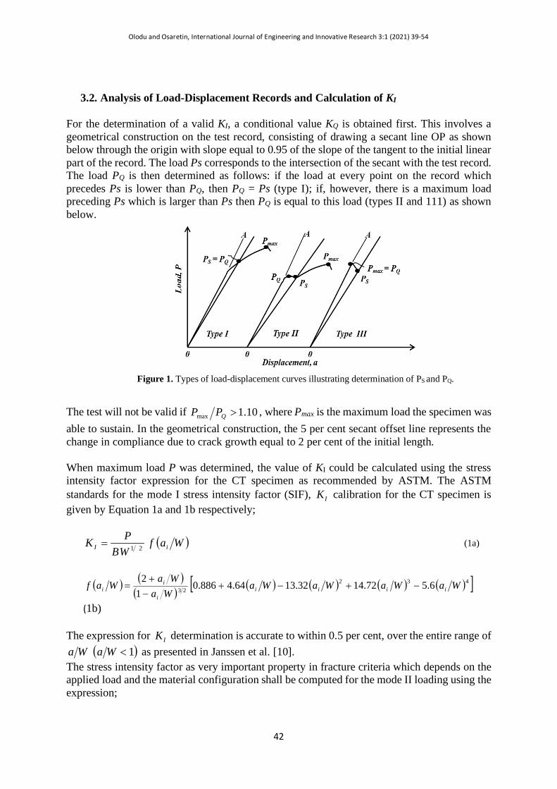
For the determination of a valid KI, a conditional value KQ is obtained first. This involves a geometrical construction on the test record, consisting of drawing a secant line OP as shown below through the origin with slope equal to 0.95 of the slope of the tangent to the initial linear part of the record. The load Ps corresponds to the intersection of the secant with the test record. The load PQ is then determined as follows: if the load at every point on the record which precedes Ps is lower than PQ, then PQ = Ps (type I); if, however, there is a maximum load preceding Ps which is larger than Ps then PQ is equal to this load (types II and 111) as shown below.
Figure 1. Types of load-displacement curves illustrating determination of PS and PQ.
The test will not be valid if 10.1max >QPP , where Pmax is the maximum load the specimen was able to sustain. In the geometrical construction, the 5 per cent secant offset line represents the change in compliance due to crack growth equal to 2 per cent of the initial length. When maximum load P was determined, the value of KI could be calculated using the stress intensity factor expression for the CT specimen as recommended by ASTM. The ASTM standards for the mode I stress intensity factor (SIF), IK calibration for the CT specimen is given by Equation 1a and 1b respectively;
( )WafWBPK iI 21= (1a)
( ) ( )( ) ( ) ( ) ( ) ( )[ ]432
23 6.572.1432.1364.4886.01
2WaWaWaWa
WaWa
Waf iiiii
ii −+−+
−+
=
(1b)
The expression for IK determination is accurate to within 0.5 per cent, over the entire range of ( )1<WaWa as presented in Janssen et al. [10].
The stress intensity factor as very important property in fracture criteria which depends on the applied load and the material configuration shall be computed for the mode II loading using the expression;
Olodu and Osaretin, International Journal of Engineering and Innovative Research 3:1 (2021) 39-54
43
aK nII πτ θ= (2) where θτ n is the shear stress parallel to the crack shall be determined using the stress transformation by method of equation. From the wedge method of stress transformation, we have that; the force in the y direction is given by;
( ) ( )tBP yxyy ∆⋅∆+−= θτθσ cossin (3)
From equilibrium of forces in the t direction on the force wedge, we obtain the shear stress, τnθ as a function of σyy, τxy and θ; where the shear plane, t inclination angle, θ = 38.7o, σxx = 0.
( )θθτθθσθθστ θ
22 sincoscossinsincos −++−= yxyyxxn (4) The theory proposed by Waddoups et al. stated in Gdoutos is based on the generalised concept of the process zone that the actual crack length is extended by the length of the process zone which is taken equal to a damage zone at the crack tip. Hence, for a crack length of a, the critical stress, Cσ shall be determined according to the stress intensity factor criterion, expressed by;
( )+=
aK IC
C πσ
(5) where is the damage zone at each crack tip and it will be determined from experiment near failure along the crack ligament. 3.3. Analysis of Stress Field near the Crack Tip The study of stress and displacement fields near the crack tip is very important, because these fields govern the fracture process that takes place at the crack tip and the damage zone. In this section, study of the stresses and displacements near the crack tip for the crack opening deformation modes was analysed, using the Westerguaard equation for stress distribution in the y-direction. The equation is given by;
+=
23sin
2sin1
2cos
2θθθ
πσ
rKI
y
(6) where KI is the mode I stress intensity factor, σy is the stress at a location, r around the crack at angle, θ. 3.4. The Charpy Impact Test The purpose of the Charpy impact test is to measure the energy absorption capacity of the reinforced polyester composite materials [11]. A notched bar of reinforced composite specimen was supported as a simple beam so that the vertical faces away from the point of impact and is struck at the middle using a hammer as incorporated on the test equipment. The impact test had a setup similar to the 3PB test and this is the most appropriate for the composite material, which damage and fracture in a brittle manner because of the case of the presence of micro defect or
Olodu and Osaretin, International Journal of Engineering and Innovative Research 3:1 (2021) 39-54
44
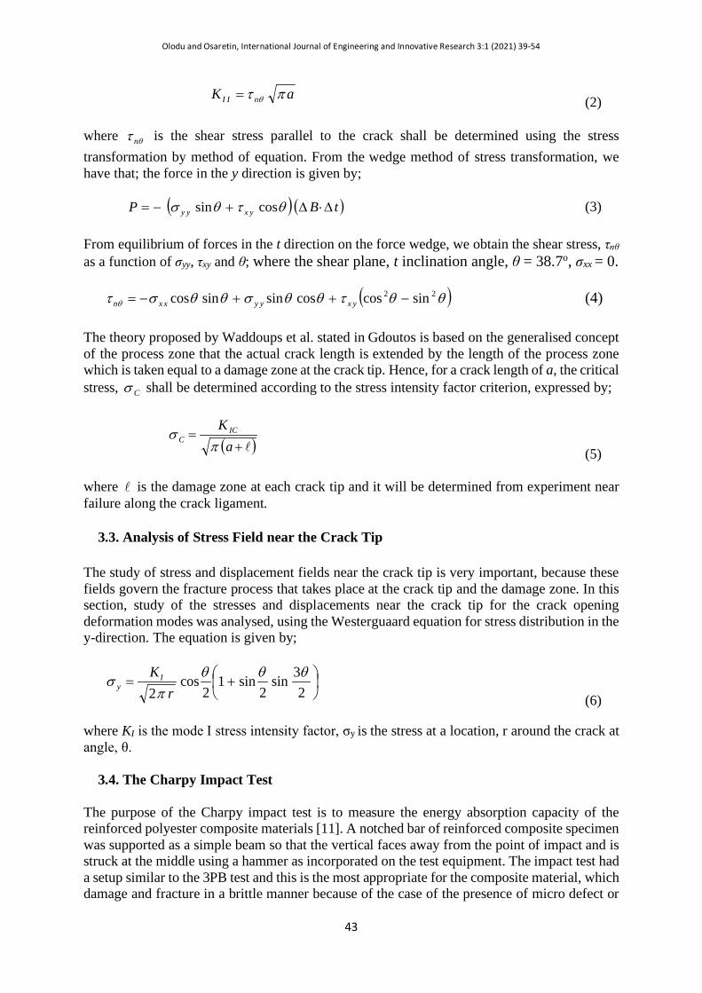
a surface scratch; and the stress concentrated at these regions as this will accelerate the failure rate under sudden impact force. The energy which is absorbed by the blow is determined by a measuring device on the machine. The size of the tested specimen and the experiment setup is shown in the figures below;
Figure 2. ASTM standard Notched Charpy Impact Test specimen.
Figure 3. Charpy Impact Test Specimen setup.
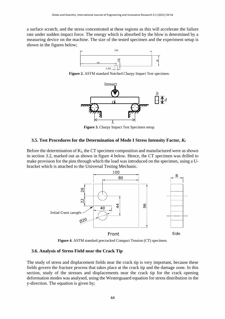
3.5. Test Procedures for the Determination of Mode I Stress Intensity Factor, KI Before the determination of KI, the CT specimen composition and manufactured were as shown in section 3.2, marked out as shown in figure 4 below. Hence, the CT specimen was drilled to make provision for the pins through which the load was introduced on the specimen, using a U-bracket which is attached to the Universal Testing Mechanic.
Figure 4. ASTM standard precracked Compact Tension (CT) specimen.
3.6. Analysis of Stress Field near the Crack Tip The study of stress and displacement fields near the crack tip is very important, because these fields govern the fracture process that takes place at the crack tip and the damage zone. In this section, study of the stresses and displacements near the crack tip for the crack opening deformation modes was analysed, using the Westerguaard equation for stress distribution in the y-direction. The equation is given by;
d c
Impact
b
L
Olodu and Osaretin, International Journal of Engineering and Innovative Research 3:1 (2021) 39-54
45
+=
23sin
2sin1
2cos
2θθθ
πσ
rKI
y (7)
where KI is the mode I stress intensity factor, σy is the stress at a location, r around the crack at angle, θ. 4. RESULTS AND DISCUSSIONS 4.1. Load, P (kN) versus Displacement, δ (m) Test Data and Plots The load – displacement plot was obtained for all specimens from experimental data, and this provided the platform for the fracture mechanics analysis on each specimen, containing varied fibre volume fraction and form, using the compact tension specimen, as shown above under tensile load condition on the universal testing machine. As the load was gradually applied and varied at a constant rate of 0.55mm per minute, then the crosshead vertical displacement data obtained as well as the increase in crack length as it propagated along the ligament and a successive interval of 5mm. These measurements were successful carried out by marking the crack growth front as it advanced. The determination of the maximum load, P lead to the determination of the stress intensities. 4.2. Data Analysis of Stress, σy Distribution in the Neighbourhood of Crack
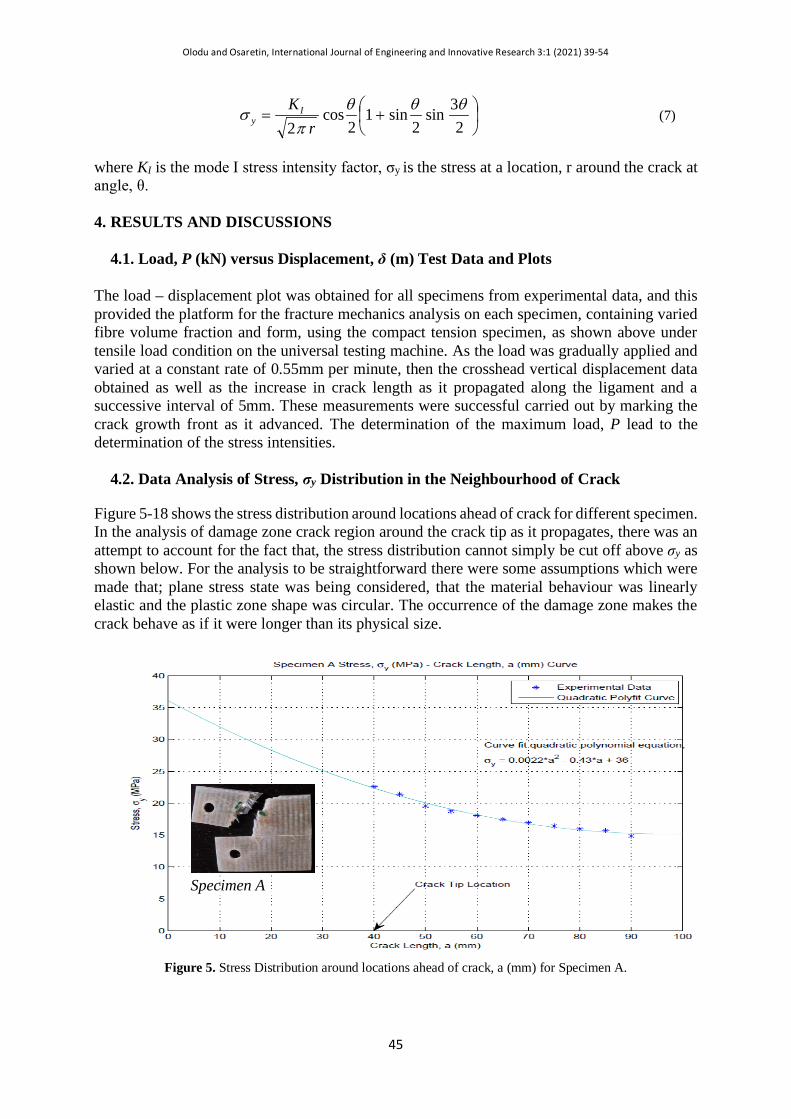
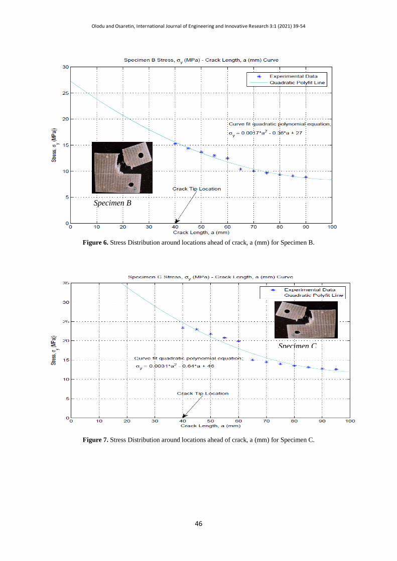
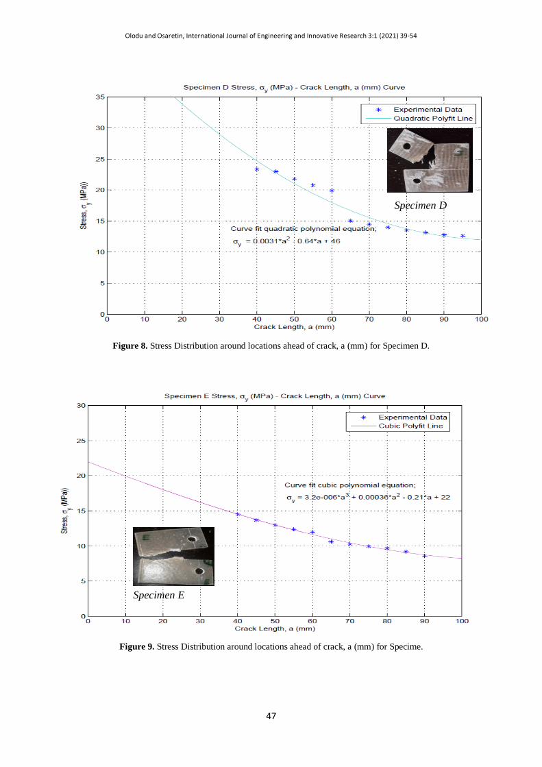
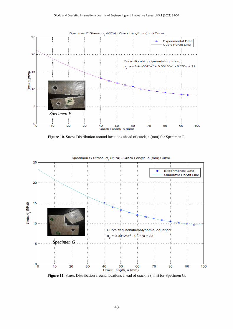
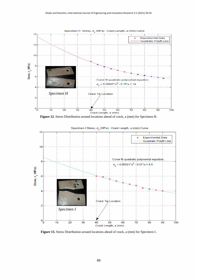
Figure 5-18 shows the stress distribution around locations ahead of crack for different specimen. In the analysis of damage zone crack region around the crack tip as it propagates, there was an attempt to account for the fact that, the stress distribution cannot simply be cut off above σy as shown below. For the analysis to be straightforward there were some assumptions which were made that; plane stress state was being considered, that the material behaviour was linearly elastic and the plastic zone shape was circular. The occurrence of the damage zone makes the crack behave as if it were longer than its physical size.
Figure 5. Stress Distribution around locations ahead of crack, a (mm) for Specimen A.
Specimen A
Olodu and Osaretin, International Journal of Engineering and Innovative Research 3:1 (2021) 39-54
46
Figure 6. Stress Distribution around locations ahead of crack, a (mm) for Specimen B.
Figure 7. Stress Distribution around locations ahead of crack, a (mm) for Specimen C.
Specimen B
Specimen C
Olodu and Osaretin, International Journal of Engineering and Innovative Research 3:1 (2021) 39-54
47
Figure 8. Stress Distribution around locations ahead of crack, a (mm) for Specimen D.
Figure 9. Stress Distribution around locations ahead of crack, a (mm) for Specime.
Specimen D
Specimen E
Olodu and Osaretin, International Journal of Engineering and Innovative Research 3:1 (2021) 39-54
48
Figure 10. Stress Distribution around locations ahead of crack, a (mm) for Specimen F.
Figure 11. Stress Distribution around locations ahead of crack, a (mm) for Specimen G.
Specimen F
Specimen G
Olodu and Osaretin, International Journal of Engineering and Innovative Research 3:1 (2021) 39-54
49
Figure 12. Stress Distribution around locations ahead of crack, a (mm) for Specimen H.
Figure 13. Stress Distribution around locations ahead of crack, a (mm) for Specimen I.
Specimen H
Specimen I
Olodu and Osaretin, International Journal of Engineering and Innovative Research 3:1 (2021) 39-54
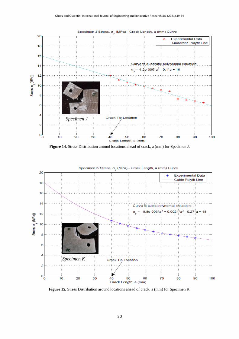
50
Figure 14. Stress Distribution around locations ahead of crack, a (mm) for Specimen J.
Figure 15. Stress Distribution around locations ahead of crack, a (mm) for Specimen K.
Specimen J
Specimen K

Olodu and Osaretin, International Journal of Engineering and Innovative Research 3:1 (2021) 39-54
51
Figure 16. Stress Distribution around locations ahead of crack, a (mm) for Specimen L.
Figure 17. Stress Distribution around locations ahead of crack, a (mm) for Specimen M.
Specimen L
Specimen M
Olodu and Osaretin, International Journal of Engineering and Innovative Research 3:1 (2021) 39-54
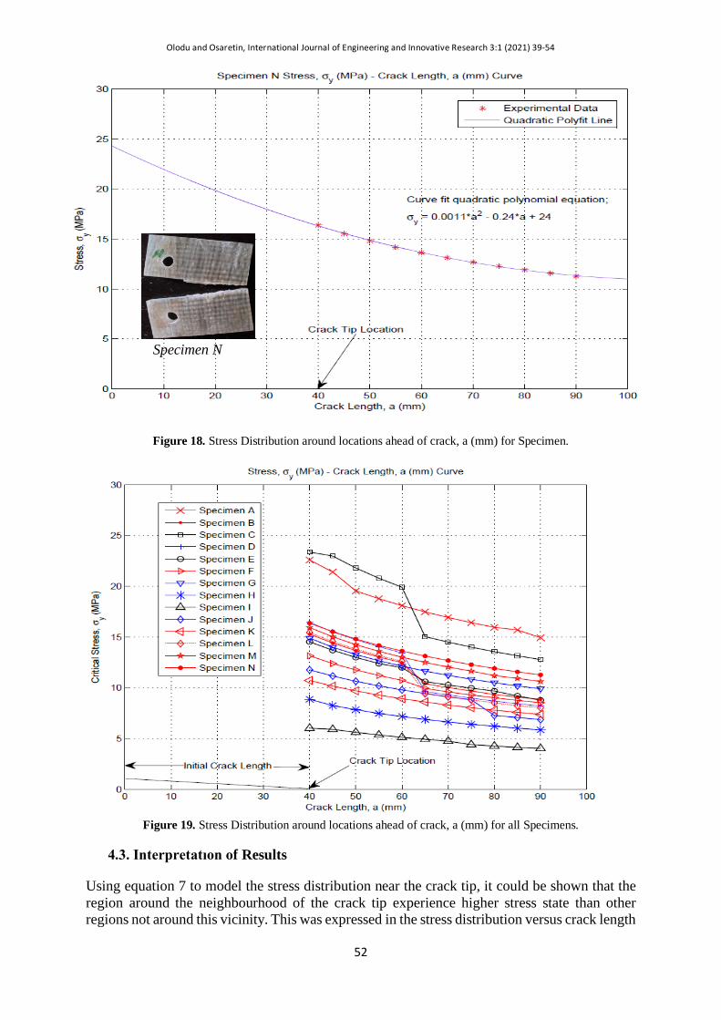
52
Figure 18. Stress Distribution around locations ahead of crack, a (mm) for Specimen.
Figure 19. Stress Distribution around locations ahead of crack, a (mm) for all Specimens.
4.3. Interpretatıon of Results
Using equation 7 to model the stress distribution near the crack tip, it could be shown that the region around the neighbourhood of the crack tip experience higher stress state than other regions not around this vicinity. This was expressed in the stress distribution versus crack length
Specimen N

Olodu and Osaretin, International Journal of Engineering and Innovative Research 3:1 (2021) 39-54
53
curve as shown in figures 5 – 18, and figure 19 showing the variation in stress distribution for all the specimens. Taking a look at the fracture mode of the CT specimens under mode I loading condition, it was observed that fracture of specimens containing woven roving namely; specimen A, B, C, D, G, , J, K, and M with the exception of specimen N, was not all along or in the direction of the original crack. The crack was observed to change direction as it propagate at an angle that was almost at 90o to the horizontal, without any crack growth in the initial crack direction, although this was not the case for all of them as some were seen to grow in the initial crack direction before change direction. The change in crack growth direction was a resistance posed by crack arrest from fibre bridging. This was also observed from the curves to result a decreased in the stress at the location. This could be explained as a change in direction as the crack grows will require a reduced stress level to grow the crack in that direction as the stress intensity at these locations are excessively higher. But for specimens E, F, H, I with the exception of specimen N contained soft and hard mat reinforcements. The cracks were observed to grow along the initial crack direction as a result of the reinforcement composition as this followed the LEFM principle. This could be raced to the form and mechanical properties of the fibre used which could not resist the crack growth efficiently. This shows that composites containing woven roving reinforcement were better fracture resistant composite material than soft and hard reinforcement mats. The weaving pattern of the woven roving was a key factor which contributed to its distinguished performance. From figure 13, it be shown that specimen I which contained 12 plies of soft mat reinforcement required the least stress magnitude to grow the crack, while specimen C which contained 2 plies of woven roving and one ply of hat mat experienced the highest critical stress.
5. CONCLUSIONS It was observed from the stress intensity and critical stress versus crack length curve, that the crack tip is where the maximum stress exists but also, the location of the minimum stress intensity factor. This is an indication that glass reinforced polyester composites has the tendencies to resist damage and crack propagation when exposed to sudden impact force, if the internal structure and surface are void of defects and microcracks resulting from blisters, foreign particle, holes and fibre-matrix debonds, i.e. the energy required to grow the crack will be inactivated or equal to zero. During sudden impact force, the effect was found to be transferred in a wave-like fashion through and across the entire region and cross section of the material, and this result to bending the material which gives rise to matrix cracking before the debonding of fibres, thereby exposing them to tensile stress especially with the tip of defect experiencing the maximum stress. The stress intensity factor versus thickness curve reveals that the size effect also manifests in composite materials. This was revealed in the decreasing trend of the plot as the thickness increased, and that the thickness range best for tailoring reinforced polyester composite was 3-4mm. The critical stress was observed to be very high for reinforced polyester composite specimens with smaller thickness compared to those with higher thickness, which showed lower critical stress values. REFERENCES
[1]Radif, Z. S. and Ali, A. Fracture Toughness of Kenaf Mat Reinforced Polyester Composite. Pertanika Journal of Science and Technology. 99(1), 177-187, 2001.
[2]Làszló, P. K. and George, S. S. Mechanics of Composites Structures. Cambrige University Press: New York. 20-45, 2003.
[3]Edelugo, S. O. The Timed Response of Different Types of GRP Laminates on Exposure to Various Strenght of Alkaline and Acidic Environments. Journal of Advanced Material. 41(2), 79–87, 2009.
[4]Dhakal, H. N., Zhang, Z. Y., Richardson, M. O. W. and Errajhi, O. A. Z. The Low Velocity Impact Response of Non-woven Hemp Fibre Reinforced Unsaturated Polyester Composites. Advanced Polymer and Composites
Olodu and Osaretin, International Journal of Engineering and Innovative Research 3:1 (2021) 39-54
54
(APC) Research Group, Department of Mechanical and Design Engineering, University of Portsmouth. Retrieved from www.elsevier.com, 2006.
[5[Szekrényes, A. Overview on the Experimental Investigation of the Fracture Toughness in Composite Materials. Hungarian Electronic Journal of Sciences. 12, 30-38, 2007.
[6]Williams, J. G. Linear Fracture Mechanics. Advances in Polymer Science, Springer Varlag, Berlin, Heidelberg, New York. 27, 69 – 82, 1978.
[7]Mandel, J. A., Pack, S. C. and Tarazi, S. Micromechanical Studies of Crack Growth in Fibre Reinforced Materials. Engineering Fracture Mechanics. 16, 741-754, 1982.
[8]Okorie, B. A. Lecture Notes on Fracture and Fracture Mechanics. Mechanical Engineering Department, University of Nigeria, Nsukka, 2010.
[9]Parhizgar, S., Zachary, L. W. and Sun, C. T. (1982). Application of the Principle of Linear Fracture Mechanics to the Composite Materials. International Journal of Fracture Mechanics. 20, 3-15, 1982.
[10]Janssen, M., Zuidema, J. and Wanhill, R. J. H. Fracture Mechanics. (2nd Edition). New York: Spon Press. 2004.
[11]Garo, A. C. and Trotman C. K. Effect of Water on Fracture Toughness of Reinforced Composites. Engineering Fracture Mechanics Journal, 24, 34-42, 1980.


![International Research Journal of Engineering and Technology ...journal of Innovative Research in Science, Engineering and Technology Vol.2, issue 4, (2013). [7] M. Sundaram, R. Ponraj](https://img.pdfslide.us/doc/110x75/5fef8cfb88b40e1fe67508c0/international-research-journal-of-engineering-and-technology-journal-of-innovative.jpg)