Embed Size (px)
Citation preview
© ISO 2018
Hydraulic fluid power — On-line automatic particle-counting systems for liquids — Methods of calibration and validationTransmissions hydrauliques — Systèmes de comptage automatique en ligne de particules en suspension dans les liquides — Méthode d'étalonnage et de validation
Reference numberISO/FDIS 11943:2018(E)
INTERNATIONAL STANDARD
ISO/FDIS11943
FINALDRAFT
RECIPIENTS OF THIS DRAFT ARE INVITED TO SUBMIT, WITH THEIR COMMENTS, NOTIFICATION OF ANY RELEVANT PATENT RIGHTS OF WHICH THEY ARE AWARE AND TO PROVIDE SUPPOR TING DOCUMENTATION.
IN ADDITION TO THEIR EVALUATION AS BEING ACCEPTABLE FOR INDUSTRIAL, TECHNOLOGICAL, COMMERCIAL AND USER PURPOSES, DRAFT INTERNATIONAL STANDARDS MAY ON OCCASION HAVE TO BE CONSIDERED IN THE LIGHT OF THEIR POTENTIAL TO BECOME STANDARDS TO WHICH REFERENCE MAY BE MADE IN NATIONAL REGULATIONS.
ISO/TC 131/SC 6
Secretariat: BSI
Voting begins on: 20180214
Voting terminates on: 20180411
ISO/FDIS 11943:2018(E)
ii © ISO 2018 – All rights reserved
COPYRIGHT PROTECTED DOCUMENT
© ISO 2018, Published in SwitzerlandAll rights reserved. Unless otherwise specified, no part of this publication may be reproduced or utilized otherwise in any form or by any means, electronic or mechanical, including photocopying, or posting on the internet or an intranet, without prior written permission. Permission can be requested from either ISO at the address below or ISO’s member body in the country of the requester.
ISO copyright officeCh. de Blandonnet 8 • CP 401CH1214 Vernier, Geneva, SwitzerlandTel. +41 22 749 01 11Fax +41 22 749 09 [email protected]
ISO/FDIS 11943:2018(E)
Foreword ........................................................................................................................................................................................................................................ivIntroduction ..................................................................................................................................................................................................................................v1 Scope ................................................................................................................................................................................................................................. 12 Normative references ...................................................................................................................................................................................... 13 Terms and definitions ..................................................................................................................................................................................... 14 Units of measurements .................................................................................................................................................................................. 15 Test equipment....................................................................................................................................................................................................... 26 Accuracy of measuring equipment and test conditions............................................................................................... 37 Off-line APC calibration procedure ................................................................................................................................................... 38 Validation of online hydraulic equipment ................................................................................................................................. 39 Online secondary calibration of automatic particle counter ................................................................................. 710 Matching of two or more particle counters .............................................................................................................................. 811 Validation of an online dilution and particle counting system .........................................................................1112 Precautions .............................................................................................................................................................................................................1313 Identification statement ............................................................................................................................................................................14Annex A (informative) Typical online calibration and validation system design
information guide ............................................................................................................................................................................................15Annex B (informative) Hydraulic circuit design guide for online counter adaptation to a
multipass test stand .......................................................................................................................................................................................18Annex C (informative) Summary of ISO TC 131/SC 6 round robin study for online
calibration and validation .......................................................................................................................................................................22Bibliography .............................................................................................................................................................................................................................29
© ISO 2018 – All rights reserved iii
Contents Page
ISO/FDIS 11943:2018(E)
Foreword
ISO (the International Organization for Standardization) is a worldwide federation of national standards bodies (ISO member bodies). The work of preparing International Standards is normally carried out through ISO technical committees. Each member body interested in a subject for which a technical committee has been established has the right to be represented on that committee. International organizations, governmental and nongovernmental, in liaison with ISO, also take part in the work. ISO collaborates closely with the International Electrotechnical Commission (IEC) on all matters of electrotechnical standardization.
The procedures used to develop this document and those intended for its further maintenance are described in the ISO/IEC Directives, Part 1. In particular the different approval criteria needed for the different types of ISO documents should be noted. This document was drafted in accordance with the editorial rules of the ISO/IEC Directives, Part 2 (see www .iso .org/ directives).
Attention is drawn to the possibility that some of the elements of this document may be the subject of patent rights. ISO shall not be held responsible for identifying any or all such patent rights. Details of any patent rights identified during the development of the document will be in the Introduction and/or on the ISO list of patent declarations received (see www .iso .org/ patents).
Any trade name used in this document is information given for the convenience of users and does not constitute an endorsement.
For an explanation on the voluntary nature of standards, the meaning of ISO specific terms and expressions related to conformity assessment, as well as information about ISO's adherence to the World Trade Organization (WTO) principles in the Technical Barriers to Trade (TBT) see the following URL: www .iso .org/ iso/ foreword .html.
This document was prepared by Technical Committee ISO/TC 131, Fluid power systems, Subcommittee SC 6, Contamination control.
This second edition cancels and replaces the first edition (ISO 11943:1999) which has been technically revised.
This edition includes the following significant changes:
— the new SRM2806b has been taken into account for expression of µm sizes;
— there is no more intent to prepare and monitor the particle size distribution of secondary calibration suspension;
— the different validation relationships has been updated to be more severe and to make more confident the calibration of APCs;
— the round robin study is summarized in Annex C.
iv © ISO 2018 – All rights reserved

ISO/FDIS 11943:2018(E)
Introduction
In hydraulic fluid power systems, power is transmitted, and controlled, through a fluid under pressure within an enclosed circuit. The fluid is both a lubricant and a power-transmitting medium.
Reliable system performance requires control of the fluid medium. Qualitative and quantitative determination of particulate contaminant, in the fluid medium, requires precision in obtaining the sample and determining the size and distribution of contaminants.
Automatic Particle Counters (APC) are an accepted means for determining the size and size distribution of particulate contamination in fluids. Individual instrument accuracy is established through calibration performed with reference primary calibration suspensions or with secondary calibration suspensions.
APCs are being utilized online to eliminate the need for sample containers, to provide increased accuracy, and to provide for a more rapid access to particle count information. A major application of online particle counting is for evaluating filtration efficiency of hydraulic filter elements during a multipass test as defined in ISO 16889. Depending upon the type of filter tested and the capabilities of the APC used, it might be necessary to dilute the samples before flowing through the sensor.
This document establishes procedures for validation of equipment for preparation of secondary calibration suspensions and for online counting of particles with or without dilution circuits, and the online calibration of APCs. It defines a procedure to match two or more particle counters that will improve the accuracy of particulate filtration efficiency as shown, for example in ISO 16889.
© ISO 2018 – All rights reserved v

Hydraulic fluid power — On-line automatic particle-counting systems for liquids — Methods of calibration and validation
1 Scope
This document establishes methods to:
— validate equipment used to prepare secondary calibration suspensions for automatic particle counters;
— perform online secondary calibration of automatic particle counters;
— match two or more online particle counters, i.e. to make count the same number of particles at a given size by two APCs associated on line;
— validate online particle counting systems with and without online dilution as used, for example, to measure the filtration efficiency of a hydraulic filter as described in the multipass filter test in ISO 16889.
2 Normative references
The following documents are referred to in the text in such a way that some or all of their content constitutes requirements of this document. For dated references, only the edition cited applies. For undated references, the latest edition of the referenced document (including any amendments) applies.
ISO 4021, Hydraulic fluid power — Particulate contamination analysis — Extraction of fluid samples from lines of an operating system
ISO 5598, Fluid power systems and components — Vocabulary
ISO 11171:2016, Hydraulic fluid power — Calibration of automatic particle counters for liquids
ISO 121031, Road vehicles — Test contaminants for filter evaluation — Part 1: Arizona test dust
ISO 16889, Hydraulic fluid power — Filters — Multi-pass method for evaluating filtration performance of a filter element
3 Terms and definitions
For the purposes of this document, the terms and definitions given in ISO 5598 and ISO 11171 apply.
ISO and IEC maintain terminological databases for use in standardization at the following addresses:
— IEC Electropedia: available at http:// www .electropedia .org/
— ISO Online browsing platform: available at https:// www .iso .org/ obp
4 Units of measurements
The international system of units (SI) is used in accordance with ISO 80000-1.
FINAL DRAFT INTERNATIONAL STANDARD ISO/FDIS 11943:2018(E)
© ISO 2018 – All rights reserved 1

ISO/FDIS 11943:2018(E)
Throughout this document, the use of µm, [or µm(b) or µm(c)] means that particle size measurements are carried out using an automatic particle counter that has been calibrated in accordance with either ISO 11171 or this document and particle size reported as defined in ISO 11171.
5 Test equipment
5.1 Liquid automatic particle counters, requiring either calibration or verification, or a particle counter with two independent sensors.
5.2 A reference particle counter, calibrated with a reference material in accordance with ISO 11171.
5.3 ISO Medium Test Dust (ISO MTD) concentrate, in accordance with ISO 12103-1, category A3, dried at 110 °C to 150 °C for at least 1 h and for use in the test system, mixed in the test fluid, mechanically agitated, then dispersed ultrasonically with a power density of 3 000 W/m2 to 10 000 W/m2.
NOTE This standard test dust is used for filter test purposes in ISO 16889.
5.4 Test fluid, as specified in ISO 16889.
5.5 Hydraulic equipment, comprising:
a) a reservoir, pump, liquid temperature control system and instrumentation which are capable of meeting the validation requirements of Clause 8;
b) a clean-up filter capable of providing an initial fluid contamination level less than 50 particles/mL at the smallest particle size that will be validated or less than 2 % of the expected number of counts;
c) a configuration which does not alter the contaminant distribution over the anticipated test duration (refer to ISO 16889);
d) fluid sampling sections in accordance with ISO 4021;
e) a configuration which will supply contaminated liquid to the particle counters under constant flow and temperature within the limits of Table 1.
NOTE 1 A multipass test rig (see ISO 16889) can be used provided it has been validated in accordance with Clause 8 of this procedure.
NOTE 2 An alternative typical configuration which has proved to be satisfactory is given in Annex A.
5.6 Hydraulic circuit, containing dilution equipment, if required, for online counter adaptation to a filter multipass test stand.
For typical hydraulic circuit configurations, which have proven to be satisfactory, refer to Annex B.
2 © ISO 2018 – All rights reserved
ISO/FDIS 11943:2018(E)
6 Accuracy of measuring equipment and test conditions
6.1 Utilize measuring equipment with an accuracy within the limits in Table 1.
Table 1 — Accuracy of measuring equipment and test conditions
Test conditions SI unitInstrument
accuracy(± of reading)
Allowed test condition variations
Flow L/min 0,5 % 2 %Kinematic viscosity mm2/s 1 % 2 mm2/s
Pressure kPa 1 % 2 %Temperature °C 0,5 °C 1 °CTime s 0,05 s 0,1 sVolume L 1 % Mass g 0,1 mg 2 %
CAUTION — Maintaining the accuracy of test conditions, within the limits of Table 1, does not imply that by doing so the validation limits are satisfied. It has been proven that the most useful way in attaining the validation requirements, is by maintaining the accuracy of test conditions given in Table 1, along with using the proper particle counting procedures and correctly designed equipment.
7 Off-line APC calibration procedure
7.1 Conduct a sizing calibration on a particle counter when new or after major service as suggested by the particle counter manufacturer in accordance with ISO 11171.
NOTE The calibration is a primary calibration if the calibration suspension is NIST SRM 2806x where “x” is the SRM 2806 batch identification letter of the primary calibration samples. The APC then is called a ‘Reference APC’.
7.2 Use the procedures specified in ISO 11171 to determine particle coincidence error limits of the particle counter and sensor, or use the manufacturer's stated levels, provided that it has been obtained in a similar manner.
8 Validation of online hydraulic equipment
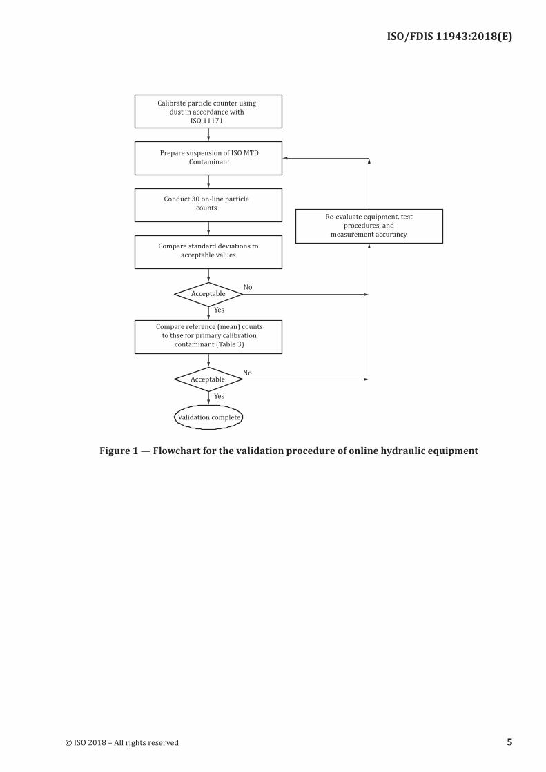
8.1 This procedure of validation demonstrates whether:
— Particle size distribution of the suspension circulating within the equipment is stable within stated limits over time.
— The sampling or bottle filling ports gives representative samples. The complete and following procedure is given in Figure 1.
8.2 Connect a single particle counter with a valid calibration as defined in Clause 7 and set it to the cumulative mode with at least six different threshold settings over the particle size range of interest. Sizes outside of this range cannot be reported as being in accordance with this document.
NOTE Since this procedure only aims at verifying the stability of particle counts over time, the use of a reference APC with primary calibration is not necessary.
© ISO 2018 – All rights reserved 3
ISO/FDIS 11943:2018(E)
8.3 Adjust the total fluid volume, expressed in L, in the suspension preparation equipment to the maximum volume it is designed to prepare and measure it within ±1 %. Maintain fluid viscosity at (15 ± 1,0) mm2/s.
8.4 Circulate the fluid at a flow rate through the clean-up filter until the fluid contamination level is < 5 particles > 5 µm per mL.
8.5 Determine the mass of ISO MTD to be introduced in the system to achieve a concentration of 3 mg/L (±0,3). Record the ISO MTD lot number.
NOTE Any other concentration can be used provided it does not produce a particle count at the lowest size that is in excess of 75 % of the particle concentration limit of the instrument determined in 7.2.
8.6 Prepare the test dust concentrate in accordance with 5.3. By-pass the clean-up filter element and add the required quantity of ISO MTD into the reservoir and allow it to circulate for approximately 15 min.
8.7 Start the test by conducting online automatic particle counts on samples with a minimal volume of 10 mL) at least at 2-min intervals for 1 h, or, at least 30 intervals spaced evenly throughout the longest period of time that the system is to be used.
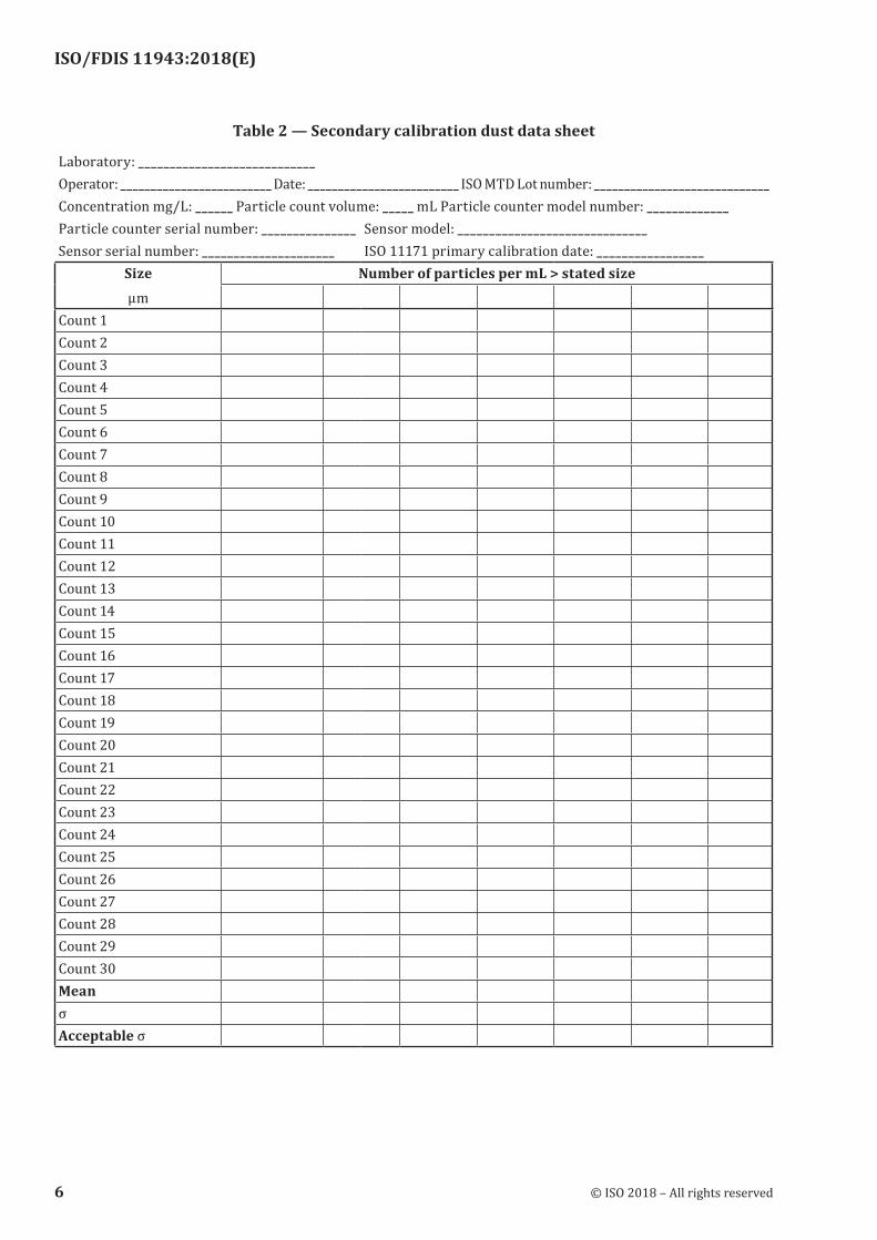
8.8 Complete Table 2 by filling in the required data. For each particle-size setting, calculate the mean� x , also the standard deviation “σ” of all the counts using the following formula:
σ =( ) ( )
( 1)
=12
=1
2n x xn n
in
i in
i∑ − ∑−
(1)
where
xi is the particles per mL for each threshold setting for sample i;
n is the total number of particle counts recorded.
8.9 Calculate the acceptable standard deviation for each particle size by using the following formula:
σ Acceptable x x= +0 00042
, (2)
NOTE This acceptable standard deviation is based upon the average standard deviation obtained in the round robin study discussed in Annex C.
8.10 Accept the validation if the standard deviation for each particle size is less than or equal to the acceptable standard deviation for that size.
8.11 If the standard deviation for a given particle size exceeds the acceptable standard deviation, then re-evaluate the hydraulic equipment and procedures, the flow rates through the APC sensor and dilution system, and particle count volumes for the online particle counting equipment. Take appropriate action and repeat the procedure from 8.3 to 8.9. If these actions do not improve the standard deviation to an acceptable level, then the APC sensor may require a service.
4 © ISO 2018 – All rights reserved
ISO/FDIS 11943:2018(E)
Figure 1 — Flowchart for the validation procedure of online hydraulic equipment
© ISO 2018 – All rights reserved 5
ISO/FDIS 11943:2018(E)
Table 2 — Secondary calibration dust data sheet
Laboratory: ____________________________Operator: _________________________ Date: _________________________ ISO MTD Lot number: _____________________________Concentration mg/L: ______ Particle count volume: _____ mL Particle counter model number: _____________Particle counter serial number: _______________ Sensor model: ______________________________Sensor serial number: _____________________ ISO 11171 primary calibration date: _________________
Sizeµm
Number of particles per mL > stated size
Count 1 Count 2 Count 3 Count 4 Count 5 Count 6 Count 7 Count 8 Count 9 Count 10 Count 11 Count 12 Count 13 Count 14 Count 15 Count 16 Count 17 Count 18 Count 19 Count 20 Count 21 Count 22 Count 23 Count 24 Count 25 Count 26 Count 27 Count 28 Count 29 Count 30 Mean σ Acceptable σ
6 © ISO 2018 – All rights reserved

ISO/FDIS 11943:2018(E)
9 Online secondary calibration of automatic particle counter
9.1 At best the on line secondary calibration of an APC has to be performed without dilution because any errors are magnified by the dilution ratio. Connect the reference APC onto the hydraulic equipment validated according to Clause 8, prepare the test dust according to 8.3, 8.4, 8.5 and 8.6. Perform at least three consecutive online counting of at least 25 mL sample volumes (after the counts have been stabilized) at several particle sizes covering the range over which the counter is to be utilized and report data on column 2 of Table 3.
9.2 Calculate and record, in column 3 of Table 3, the acceptable calibration limits for each particle size using the following formula:
Calibration limit = 0,185 (instrument counts in column 2 of Table 3)0,85
NOTE These calibration limits are based upon results issued from the round robin study (see Annex C).
9.3 Connect the APC to be calibrated onto the same hydraulic equipment as below, give the same conditions of circulation according to 9.1 and obtain a minimum of three consecutive online particle counts on 25 mL sample volumes (after the counts have stabilized). Average the counts obtained at each size, divide by the volume analysed and record the values obtained in column 4 of Table 3.
9.4 Accept the current calibration if all particle counts obtained in 9.3 are equal to the counts given by the Reference APC (in case of secondary calibration of the APC) or the secondary calibrated APC (in case of working verification of the APC) given in column 2 of Table 3 within the limits in column 3 of Table 3.
Table 3 — Online particle counts of either calibration or verification suspension
Column 1 Column 2 Column 3 Column 4
Particle size, µm
Reference or secondary
instrument counts(N/mL)
± Calibration limitsParticle counts
of APC under either calibration or
verification
>3 >4 >5 >6 >7
>10 > 12 >14 >15 >20 >30
9.5 If the particle counts obtained in 9.3 are outside the limits set, take corrective action and repeat the verification procedure described in 9.1 to 9.4.
Ensure that:
a) the proper sensor flowrate is being used;
© ISO 2018 – All rights reserved 7
ISO/FDIS 11943:2018(E)
b) the particle size threshold settings are correct;
c) the fluid is completely degassed;
d) the sample weights and volumes are correct;
e) at the end there is some possibility to interpolate the thresholds settings between verified points but it should be avoided. Extrapolation is not allowed.
10 Matching of two or more particle counters
10.1 This procedure shall be used when two or more APC are to be used upstream and downstream of a filter to measure its filtration efficiency at various sizes.
NOTE The “master” system (sensor 1) in the matching process is the system with the higher signal to noise ratio. This allows the “slave” sensor (sensor 2) a wider matching range.
10.2 In itself this procedure is not suited to performing or verifying the calibration of one or the two instruments. For calibration refer to Clause 7, and for online calibration refer to Clause 9.
10.3 Connect the APC calibrated in accordance with Clause 9 (online calibration) and another one to be matched to the sampling points described in 5.5 of a closed loop system validated in accordance with Clause 8.
The two instruments have to match together without using the dilution system.
10.4 Set the instruments to the cumulative mode and to at least six different threshold settings over the particle size range of interest.
10.5 Adjust total fluid volume, expressed in L in the hydraulic test equipment to the desired level and measure within ±1 %. Maintain fluid viscosity at (15 ± 1,0) mm2/s. The concentration of particles at any size should be statistically significant and particle counts should be at any size >10.
10.6 Circulate the fluid through the clean-up filter until the fluid contamination level is < 5 particles > 5 µm per mL
10.7 Determine the ISO MTD concentration to be used for the matching so that the maximum particle count at the lowest particle size can be approximately 75 % of the APC concentration limits determined in 7.2. Prepare in accordance with 5.3. Record the ISO MTD batch/lot number.
10.8 By-pass the clean-up filter, add the contaminant to the reservoir and mix by circulation for about 15 min or until the counts have stabilized across size range.
10.9 Start the APC matching procedure by conducting online automatic counts at 1-min intervals for the period of, at least, 30 min.
10.10 Calculate the allowable variation between sensors or counters for each particle size based upon the following formula and report in Table 5.
Allowable variation between sensors = 4,925 6 + 0,013 2 (average counts of sensor 1)
NOTE The variation between counters has been validated as well as ISO MTD, as with ISO UFTD during the last round robin study (see Annex C).
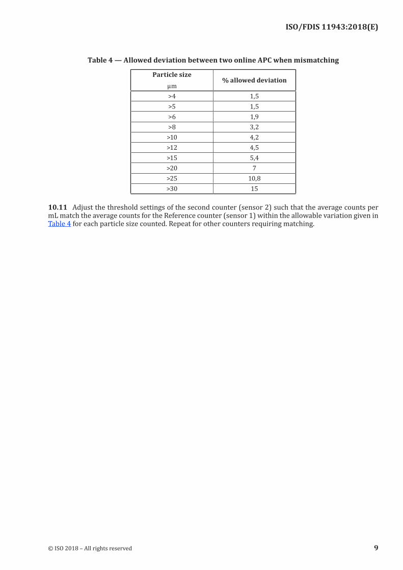
The maximum allowable particle count difference between counters shall be less than 10 % those given in Table 4, whatever the size lower than 30 µm.
8 © ISO 2018 – All rights reserved
ISO/FDIS 11943:2018(E)
Table 4 — Allowed deviation between two online APC when mismatching
Particle sizeµm
% allowed deviation
>4 1,5>5 1,5>6 1,9>8 3,2>10 4,2>12 4,5>15 5,4>20 7>25 10,8>30 15
10.11 Adjust the threshold settings of the second counter (sensor 2) such that the average counts per mL match the average counts for the Reference counter (sensor 1) within the allowable variation given in Table 4 for each particle size counted. Repeat for other counters requiring matching.
© ISO 2018 – All rights reserved 9

ISO/FDIS 11943:2018(E)
Table 5 — Data sheet for calibration verification
Laboratory: ______________________________________________Operator: _______ Date: _____ ISO MTD Lot number: ____Concentration mg/L: _____ Particle count volume: _____ mLParticle counter model number: ___________ Particle counter serial number: ______________Sensor model: ___________________________ Sensor serial number: ________________________ISO 11171 primary calibration date: _________________
Sizeµm
Number of particles per mL > stated size
Sensor 1: Model and serial number:______________________________________________
Count 1 Count 2 Count 3 Average Average Sensor 2: Model and serial number:______________________________________________
Count 1 Count 2 Count 3 Average Average Other units:
10 © ISO 2018 – All rights reserved
ISO/FDIS 11943:2018(E)
11 Validation of an online dilution and particle counting system
11.1 Perform a validation of the online dilution system, where used, at the same frequency as calibration verification. The procedure is described in Figure 2.
11.2 Use dilution fluid which has been filtered to a cleanliness level of < 5 particles > 5 µm per mL, unless it can be established that a higher level does not add more than 1 % error to the resulting particle counts.
11.3 Validate first at the minimum dilution factor to be used.
11.4 Circulate the fluid through the clean-up filter until the fluid contamination level is < 5 particles > 5 µm per mL.
11.5 Prepare an ISO MTD secondary calibration suspension in accordance with 8.3 to 8.6 but at a level equal to 75 ± 10 % of the concentration limits in 7.2, multiplied by the dilution factor selected. Record the batch number of ISO MTD.
EXAMPLE For a 2 x dilution factor (1 part diluent: 1 part suspension), use a sample concentration equal to 2 times 50 % of the counter concentration limit.
11.6 By-pass the clean-up filter, add the contaminant to the reservoir and mix by circulation for about 15 min or until the counts have stabilized across the size range, whichever occurs first.
11.7 Set the particle counter at a minimum of six particle size threshold settings covering the range of interest.
11.8 Using the dilution factor selected obtain a minimum of three 25 mL particle counts (after the counts have been stabilized) for each sensor and calculate the average count of the diluted sample for each particle size.
11.9 Calculate the average counts per mL for each particle size threshold setting dividing the average count by the fluid volume counted in mL. Record in Table 6. Use separate data sheets for both sensors 1 and 2 where used.
11.10 All particle counts obtained in 11.7 should be equal to the Reference counts, ± the calibration limits in column 3 of Table 3, for each particle size counted. In addition, when sensors 1 and 2 are being used the average counts from the two counters (sensors) shall agree within the allowable variation given in 10.10, for each particle size counted.
11.11 Repeat the procedures given in 11.4 to 11.10 at the maximum dilution factor to be used and at least two other intermediate dilution factors within the total dilution range of the system. It is
© ISO 2018 – All rights reserved 11

ISO/FDIS 11943:2018(E)
recommended that the most common dilution ratios that will be used for the equipment be checked as described in this clause.
Figure 2 — Flowchart of the procedure for online dilution system validation
12 © ISO 2018 – All rights reserved

ISO/FDIS 11943:2018(E)
Table 6 — Data sheet for validation of online dilution equipment
Laboratory: ________________________________Operator: ______________________________ Date: _______ISO MTD Lot number: ____________ Concentration mg/L: ______ Particle count volume: _____________ mLParticle counter model number: ________ Particle counter serial number: ______________Sensor model: __________________________ Sensor serial number: ________________________Is this sensor to be located upstream or downstream of the test filter? _____________ISO 11171 primary calibration date: _________________ Size µm
Number of particles per mL > stated size
Concentration: _____mg/LDilution factor: __________
Count 1 Count 2 Count 3 Average Concentration: _____mg/LDilution factor: __________
Count 1 Count 2 Count 3 Average Concentration: _____mg/LDilution factor:__________
Count 1 Count 2 Count 3 Average Concentration: _____mg/LDilution factor:__________
Count 1 Count 2 Count 3 Average
12 Precautions
12.1 Online particle counting using ISO MTD for particle sizes >40 µm requires extreme caution to ensure against particle settling. Calibration at the maximum particle sizes to be used shall be verified online (see Clause 10).
12.2 Testing coarse filters with online counters requires higher dilution factors which necessitates the use of higher-accuracy flow measurement.
12.3 Dilution is required when particle counter concentration limits are exceeded. High concentrations of undetected particles can influence particle counts at measured sizes. Higher dilution factors shall be used under these conditions.
© ISO 2018 – All rights reserved 13
ISO/FDIS 11943:2018(E)
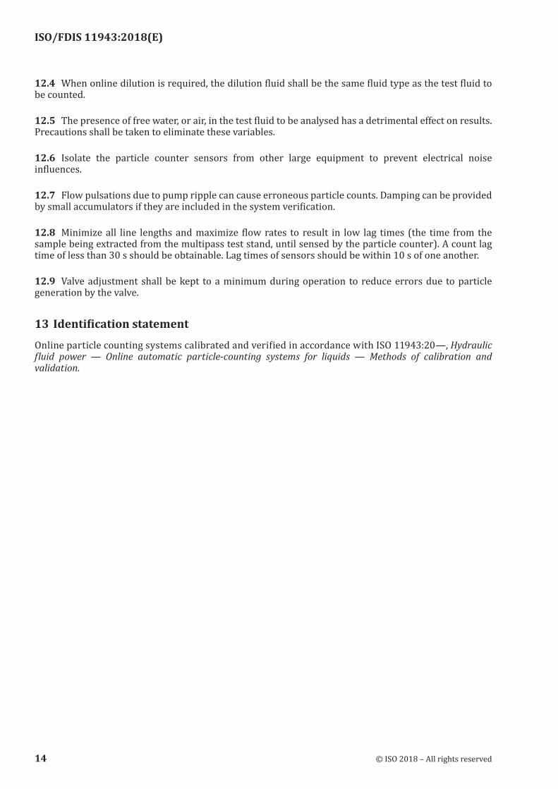
12.4 When online dilution is required, the dilution fluid shall be the same fluid type as the test fluid to be counted.
12.5 The presence of free water, or air, in the test fluid to be analysed has a detrimental effect on results. Precautions shall be taken to eliminate these variables.
12.6 Isolate the particle counter sensors from other large equipment to prevent electrical noise influences.
12.7 Flow pulsations due to pump ripple can cause erroneous particle counts. Damping can be provided by small accumulators if they are included in the system verification.
12.8 Minimize all line lengths and maximize flow rates to result in low lag times (the time from the sample being extracted from the multipass test stand, until sensed by the particle counter). A count lag time of less than 30 s should be obtainable. Lag times of sensors should be within 10 s of one another.
12.9 Valve adjustment shall be kept to a minimum during operation to reduce errors due to particle generation by the valve.
13 Identification statement
Online particle counting systems calibrated and verified in accordance with ISO 11943:20—, Hydraulic fluid power — Online automatic particle-counting systems for liquids — Methods of calibration and validation.
14 © ISO 2018 – All rights reserved

ISO/FDIS 11943:2018(E)
Annex A (informative)
Typical online calibration and validation system design
information guide
A.1 General
A.1.1 Online calibration and validation requires a validation procedure to determine the acceptability of the equipment to perform the desired function.
A.1.2 It is intended that Annex A provides basic guidance in constructing equipment that meets the validation requirements of this document.
A.1.3 The reader is cautioned that Annex A provides only guidelines for construction and does not guarantee successful validation of the equipment.
A.2 Online sample preparation equipment
A.2.1 General
The schematic of a typical set-up is shown in Figure A.1.
A.2.2 Lines
All lines should be sized for turbulent mixing flow and long straight runs should be avoided.
A.2.3 Fittings
Fittings should not have internally exposed threads or lips that can be contaminant traps.
A.2.4 Lines and fittings
Lines and fittings should be arranged to eliminate dead flow zones and where possible, vertical runs are preferable to horizontal.
A.2.5 Valves
Ball valves are preferable to other types of valves because all valves are not contaminant traps and have a self-cleaning action. The valves should only be used in the full on or off positions and not for flow control.
A.2.6 Reservoir
The reservoir with a small volume, typically less than 10 L, should be constructed with a conical bottom displaying an included angle of not more than 90° with the entering test fluid diffused below the fluid surface.
NOTE Small reservoir volumes can cause a problem in accurately weighing the required quantity of test dust due to its low mass.
© ISO 2018 – All rights reserved 15

ISO/FDIS 11943:2018(E)
A.2.7 Clean-up filter
The system clean-up filter shall be capable of providing the required initial system contamination level. A filter with a filtration ratio of f β > 1 000 at the smallest particle size of interest is recommended.
A.2.8 Heat exchanger/heater
Depending upon the system design, cooling or heating of the system fluid may be necessary but take care as any heat exchanger may cause sedimentation. That is the reason why a conventional shell tube-type heat exchanger with oil flowing through the tubes, or a reservoir with a double jacket in which a temperature-controlled fluid is circulated, is recommended for cooling or heating the test fluid.
16 © ISO 2018 – All rights reserved
ISO/FDIS 11943:2018(E)
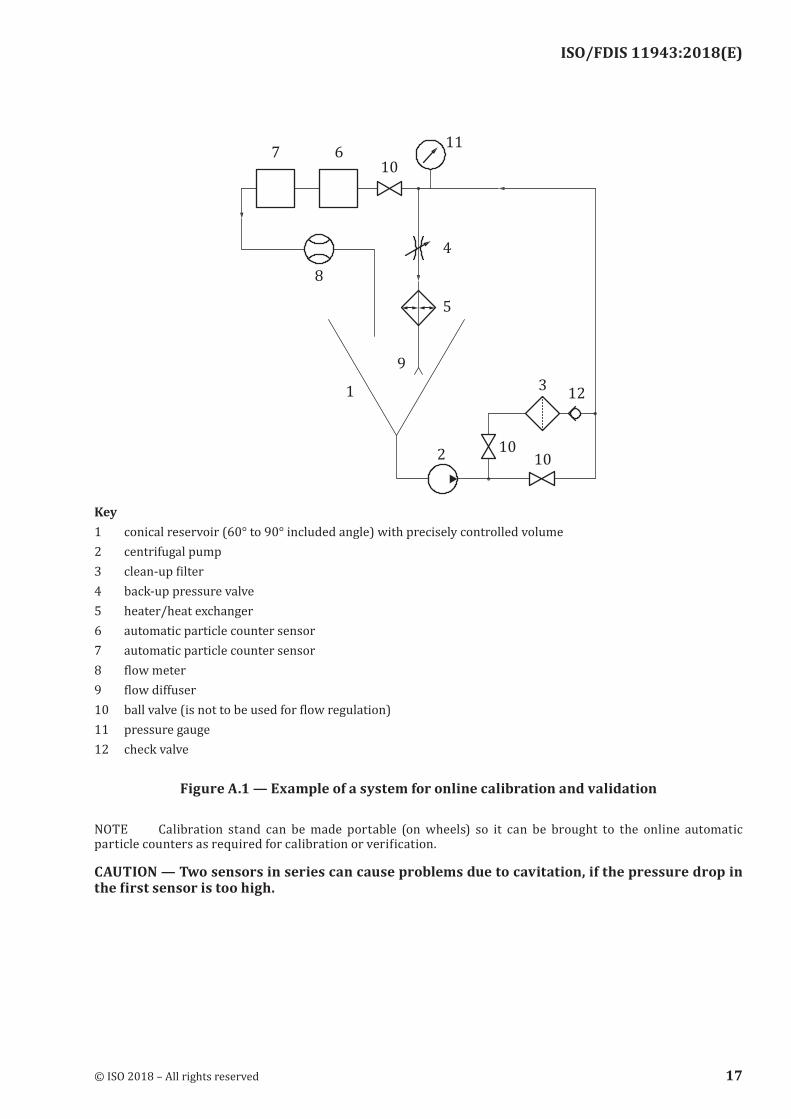
Key1 conical reservoir (60° to 90° included angle) with precisely controlled volume2 centrifugal pump3 clean-up filter4 backup pressure valve5 heater/heat exchanger6 automatic particle counter sensor7 automatic particle counter sensor8 flow meter9 flow diffuser10 ball valve (is not to be used for flow regulation)11 pressure gauge12 check valve
Figure A.1 — Example of a system for online calibration and validation
NOTE Calibration stand can be made portable (on wheels) so it can be brought to the online automatic particle counters as required for calibration or verification.
CAUTION — Two sensors in series can cause problems due to cavitation, if the pressure drop in the first sensor is too high.
© ISO 2018 – All rights reserved 17
ISO/FDIS 11943:2018(E)
Annex B (informative)
Hydraulic circuit design guide for online counter adaptation to a
multipass test stand
B.1 General
B.1.1 Online particle counting (with or without dilution) during a multipass test requires adaptation to the multipass test stand and pre-test validation of the set-up to determine the acceptability of the equipment to perform the desired function.
B.1.2 It is intended that Annex B provides some basic guidance in constructing equipment that meets the validation requirements of this document.
B.1.3 The reader is cautioned that Annex B provides only guidelines for construction and does not guarantee successful validation of the equipment.
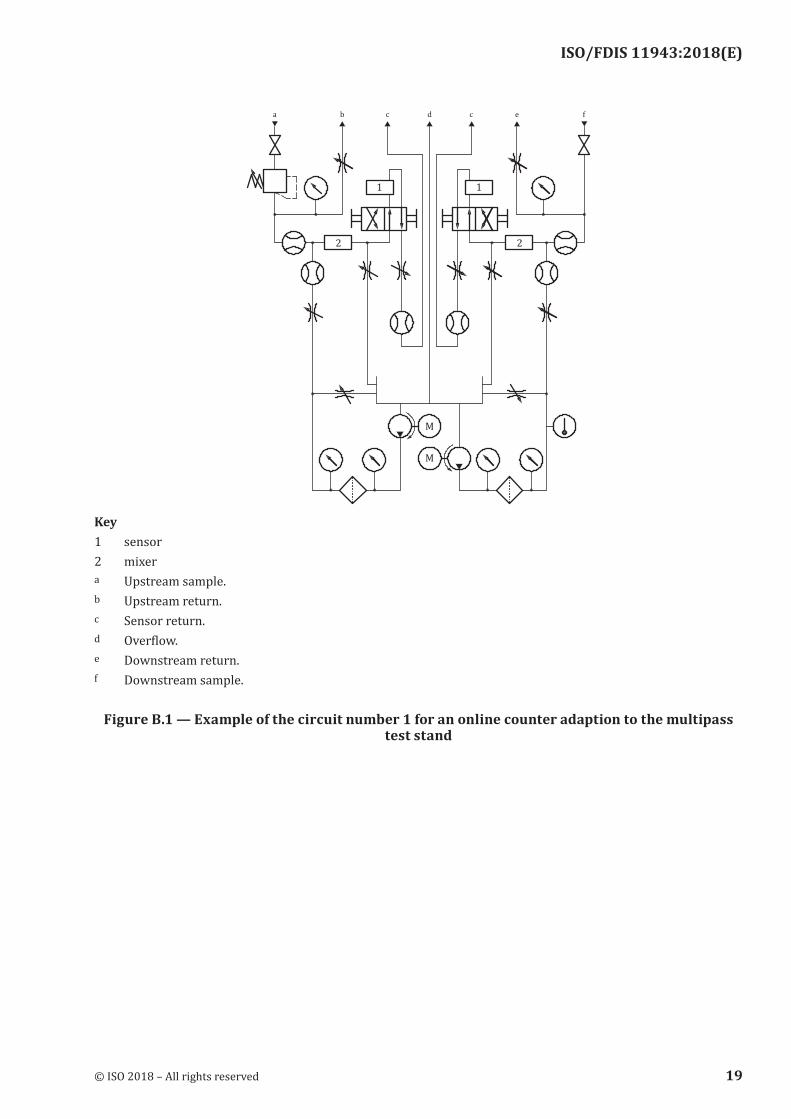
B.1.4 Schemes of three typical set-ups, which have been proven to be successful, are shown in Figures B.1, B.2 and B.3.
B.1.5 The system component design guide for the online sample preparation equipment, given in Annex A, should be followed for the online counting and dilution system.
18 © ISO 2018 – All rights reserved
ISO/FDIS 11943:2018(E)
Key1 sensor2 mixera Upstream sample.b Upstream return.c Sensor return.d Overflow.e Downstream return.f Downstream sample.
Figure B.1 — Example of the circuit number 1 for an online counter adaption to the multipass test stand
© ISO 2018 – All rights reserved 19
ISO/FDIS 11943:2018(E)
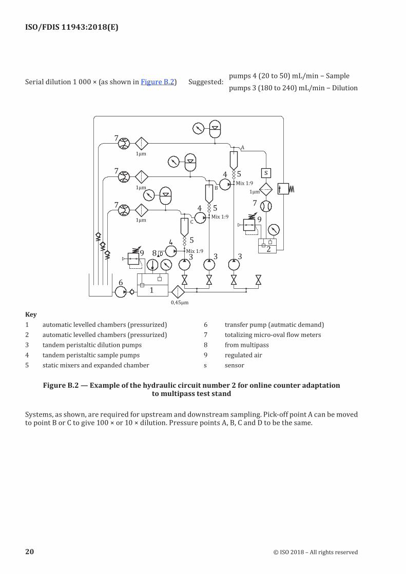
Serial dilution 1 000 × (as shown in Figure B.2) Suggested:pumps 4 (20 to 50) mL/min − Samplepumps 3 (180 to 240) mL/min − Dilution
Key1 automatic levelled chambers (pressurized) 6 transfer pump (autmatic demand)2 automatic levelled chambers (pressurized) 7 totalizing micro-oval flow meters3 tandem peristaltic dilution pumps 8 from multipass4 tandem peristaltic sample pumps 9 regulated air5 static mixers and expanded chamber s sensor
Figure B.2 — Example of the hydraulic circuit number 2 for online counter adaptation to multipass test stand
Systems, as shown, are required for upstream and downstream sampling. Pick-off point A can be moved to point B or C to give 100 × or 10 × dilution. Pressure points A, B, C and D to be the same.
20 © ISO 2018 – All rights reserved
ISO/FDIS 11943:2018(E)
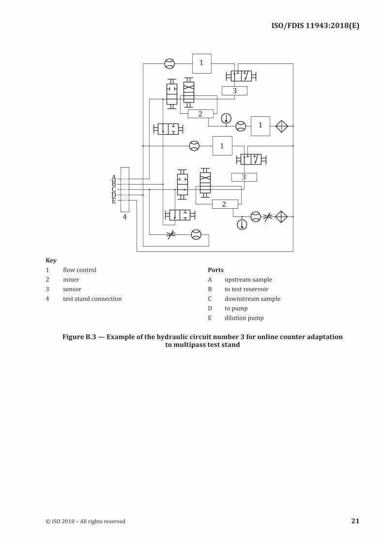
Key1 flow control Ports2 mixer A upstream sample3 sensor B to test reservoir4 test stand connection C downstream sample
D to pumpE dilution pump
Figure B.3 — Example of the hydraulic circuit number 3 for online counter adaptation to multipass test stand
© ISO 2018 – All rights reserved 21
ISO/FDIS 11943:2018(E)
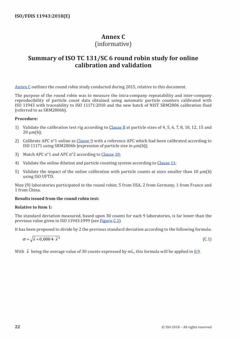
Annex C (informative)
Summary of ISO TC 131/SC 6 round robin study for online
calibration and validation
Annex C outlines the round robin study conducted during 2015, relative to this document.
The purpose of the round robin was to measure the intra-company repeatability and inter-company reproducibility of particle count data obtained using automatic particle counters calibrated with ISO 11943 with traceability to ISO 11171:2010 and the new batch of NIST SRM2806 calibration fluid (referred to as SRM2806b).
Procedure:
1) Validate the calibration test rig according to Clause 8 at particle sizes of 4, 5, 6, 7, 8, 10, 12, 15 and 20 µm(b);
2) Calibrate APC n°1 online as Clause 9 with a reference APC which had been calibrated according to ISO 11171 using SRM2806b [expression of particle size in µm(b)];
3) Match APC n°1 and APC n°2 according to Clause 10;
4) Validate the online dilution and particle counting system according to Clause 11;
5) Validate the impact of the online calibration with particle counts at sizes smaller than 10 µm(b) using ISO UFTD.
Nine (9) laboratories participated in the round robin; 5 from USA, 2 from Germany, 1 from France and 1 from China.
Results issued from the round robin test:
Relative to Item 1:
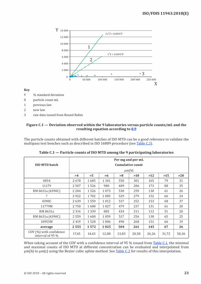
The standard deviation measured, based upon 30 counts for each 9 laboratories, is far lower than the previous value given in ISO 11943:1999 (see Figure C.1).
It has been proposed to divide by 2 the previous standard deviation according to the following formula:
σ = + ⋅x x0 0004, ² (C.1)
With � x being the average value of 30 counts expressed by mL, this formula will be applied in 8.9.
22 © ISO 2018 – All rights reserved
ISO/FDIS 11943:2018(E)
KeyY % standard deviationX particle count mL1 previous law2 new law3 raw data issued from Round Robin
Figure C.1 — Deviation observed within the 9 laboratories versus particle counts/mL and the resulting equation according to 8.9
The particle counts obtained with different batches of ISO MTD can be a good reference to validate the multipass test benches such as described in ISO 16889 procedure (see Table C.1).
Table C.1 — Particle counts of ISO MTD among the 9 participating laboratories
Per mg and per mLISO MTD batch Cumulative count
µm(b)>4 >5 >6 >8 >10 >12 >15 >20
4854 2 678 1 685 1 101 550 301 165 79 3111179 2 507 1 526 980 489 286 173 88 35
RM 8631a (4390C) 2 204 1 526 1 073 530 259 130 61 26? 2 922 1 702 1 085 529 279 152 66 24
4390C 2 639 1 559 1 012 517 252 153 68 3711779M 2 750 1 680 1 027 479 237 131 61 20
RM 8631a 2 314 1 339 885 434 211 112 51 20RM 8631a (4390C) 2 559 1 600 1 059 517 256 138 65 25
10955M 2 419 1 528 1 006 490 268 151 66 19average 2 555 1 572 1 025 504 261 145 67 26
COV (%) with confidence interval of 95 % 17,45 14,43 12,88 13,83 20,58 26,26 31,72 50,36
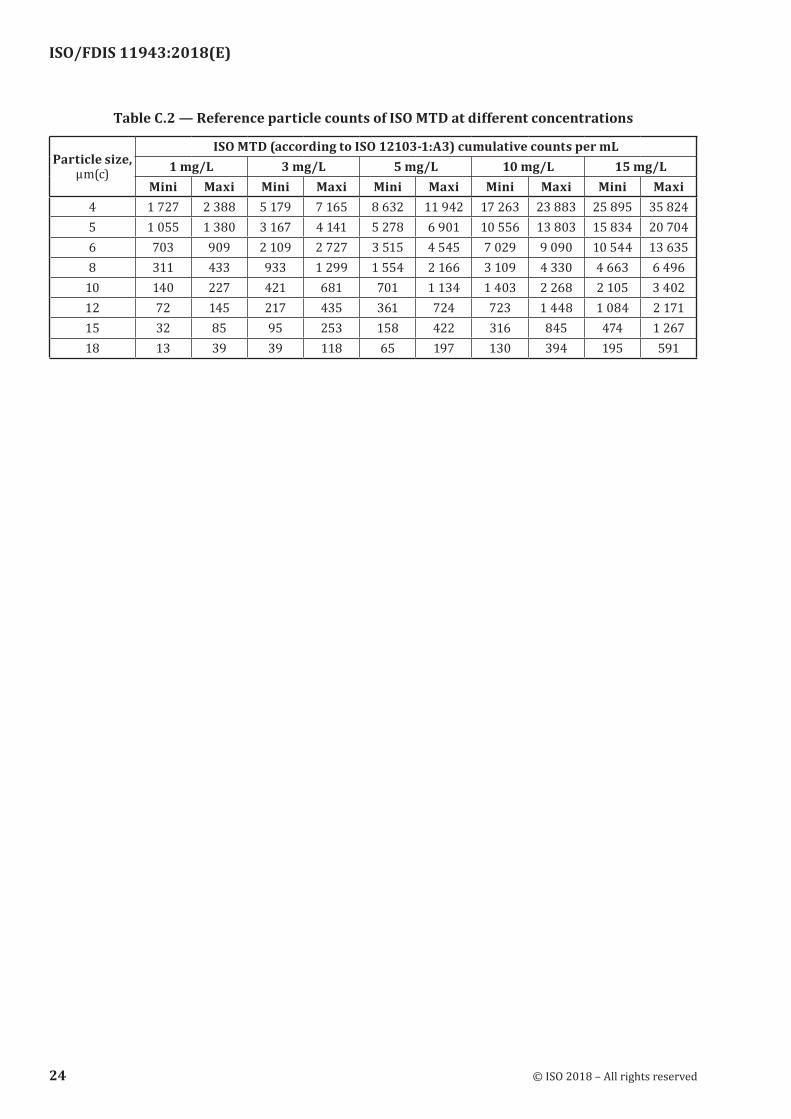
When taking account of the COV with a confidence interval of 95 % issued from Table C.1, the minimal and maximal counts of ISO MTD at different concentration can be evaluated and interpolated from µm(b) to µm(c) using the Bezier cubic spline method. See Table C.2 for results of this interpolation.
© ISO 2018 – All rights reserved 23
ISO/FDIS 11943:2018(E)
Table C.2 — Reference particle counts of ISO MTD at different concentrations
Particle size, µm(c)
ISO MTD (according to ISO 12103-1:A3) cumulative counts per mL1 mg/L 3 mg/L 5 mg/L 10 mg/L 15 mg/L
Mini Maxi Mini Maxi Mini Maxi Mini Maxi Mini Maxi4 1 727 2 388 5 179 7 165 8 632 11 942 17 263 23 883 25 895 35 8245 1 055 1 380 3 167 4 141 5 278 6 901 10 556 13 803 15 834 20 7046 703 909 2 109 2 727 3 515 4 545 7 029 9 090 10 544 13 6358 311 433 933 1 299 1 554 2 166 3 109 4 330 4 663 6 496
10 140 227 421 681 701 1 134 1 403 2 268 2 105 3 40212 72 145 217 435 361 724 723 1 448 1 084 2 17115 32 85 95 253 158 422 316 845 474 1 26718 13 39 39 118 65 197 130 394 195 591
24 © ISO 2018 – All rights reserved

ISO/FDIS 11943:2018(E)
Relative to Item 2:
KeyY % standard deviationX particle count mL1 previous law2 new law3 raw data issued from round robin
Figure C.2 — Calibration limit law between reference APC and APC under calibration with using ISO MTD
The data that has been obtained will reduce the allowed deviation between the APC to be calibrated with the reference APC when using ISO MTD as reference particle at different concentrations.
Based upon data reported on Figure C.2, the previous relationship relative to the ISO 11943:1999 version:
Calibration limit = 0,37 (instrument counts in column 2 of Table 3)0,85
can be removed and replaced by the following law (which correspond to the previous law divided by 2):
Calibration limit = 0,185 (instrument counts in column 2 of Table 3)0,85
This formula will be applied in 9.2.
Relative to Item 3:
Furthermore, the obtained data may reduce the allowed deviation between two APCs when mismatching them. This has a positive impact upon the accuracy of determination of the particulate efficiency of liquid filters. The allowed deviation is much narrower than the one given in the ISO 11943:1999 version (see Figure C.3).
The formula follows, (see also 10.10):
Allowable variation between sensors = 4,925 6 + 0,013 2 (average counts of sensor 1)
© ISO 2018 – All rights reserved 25

ISO/FDIS 11943:2018(E)
KeyY % standard deviation 2 linèar (new law)X particle count mL 3 new law1 previous law 4 raw data issued from round robin
NOTE Allowed deviation (%) = 0,013 2 (particle count) + 4,925 6
Figure C.3 — Mismatching relationship between two APCs
Relative to Item 4:
There were not enough participating laboratories to validate some new online dilution criteria. They have been kept unchanged according to the ISO 11943:1999 version.
Relative to Item 5:
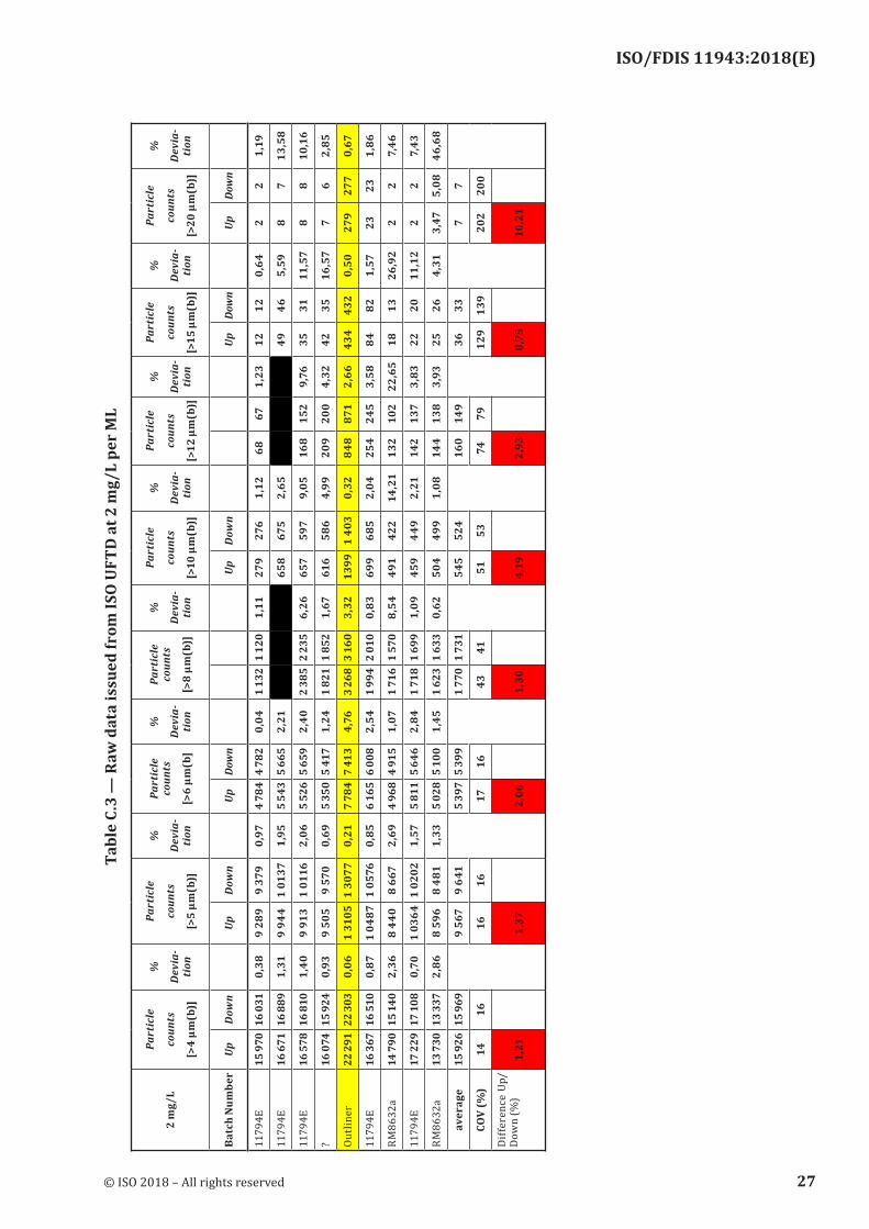
Using ISO UFTD allows validation and confirmation of the mismatching relationship between two APC at small particle sizes [<10 µm (b)]. The results are shown in Table C.3
26 © ISO 2018 – All rights reserved
ISO/FDIS 11943:2018(E)
Tabl
e C.
3 —
Raw
dat
a is
sued
from
ISO
UFT
D a
t 2 m
g/L
per
ML
2 m
g/L
Part
icle
coun
ts
[>4
µm(b
)]
%
Dev
ia-
tion
Part
icle
coun
ts
[>5
µm(b
)]
%
Dev
ia-
tion
Part
icle
co
unts
[>6
µm(b
]
%
Dev
ia-
tion
Part
icle
co
unts
[>8
µm(b
)]
%
Dev
ia-
tion
Part
icle
coun
ts
[>10
µm
(b)]
%
Dev
ia-
tion
Part
icle
coun
ts
[>12
µm
(b)]
%
Dev
ia-
tion
Part
icle
coun
ts
[>15
µm
(b)]
%
Dev
ia-
tion
Part
icle
coun
ts
[>20
µm
(b)]
%
Dev
ia-
tion
Bat
ch N
umbe
rUp
Dow
n
UpD
own
Up
Dow
n
Up
Dow
n
Up
Dow
n
UpDo
wn
1179
4E15
970
16 0
310,
389
289
9 37
90,
974
784
4 78
20,
041
132
1 12
01,
1127
927
61,
1268
671,
2312
120,
642
21,
19
1179
4E16
671
16 8
891,
319
944
1 01
371,
955
543
5 66
52,
21
658
675
2,65
49
465,
598
713
,58
1179
4E16
578
16 8
101,
409
913
1 01
162,
065
526
5 65
92,
402
385
2 23
56,
2665
759
79,
0516
815
29,
7635
3111
,57
88
10,1
6
?16
074
15 9
240,
939
505
9 57
00,
695
350
5 41
71,
241
821
1 85
21,
6761
658
64,
9920
920
04,
3242
3516
,57
76
2,85
Out
liner
22 2
9122
303
0,06
1 31
051
3077
0,21
7 78
47
413
4,76
3 26
83
160
3,32
139
91
403
0,32
848
871
2,66
434
432
0,50
279
277
0,67
1179
4E16
367
16 5
100,
871
0487
1 05
760,
856
165
6 00
82,
541
994
2 01
00,
8369
968
52,
0425
424
53,
5884
821,
5723
231,
86
RM
8632
a14
790
15 1
402,
368
440
8 66
72,
694
968
4 91
51,
071
716
1 57
08,
5449
142
214
,21
132
102
22,6
518
1326
,92
22
7,46
1179
4E17
229
17 1
080,
701
0364
1 02
021,
575
811
5 64
62,
841
718
1 69
91,
0945
944
92,
2114
213
73,
8322
2011
,12
22
7,43
RM
8632
a13
730
13 3
372,
868
596
8 48
11,
335
028
5 10
01,
451
623
1 63
30,
6250
449
91,
0814
413
83,
9325
264,
313,
475,
0846
,68
aver
age
15 9
2615
969
9 56
79
641
5 39
75
399
1 77
01
731
545
524
160
149
3633
77
CO
V (%
)14
1616
1617
1643
4151
5374
7912
913
920
220
0
Dif
fere
nce
Up/
Dow
n (%
)1,
21
1,37
2,
06
1,30
4,
19
2,93
8,
75
10,2
1
© ISO 2018 – All rights reserved 27
ISO/FDIS 11943:2018(E)
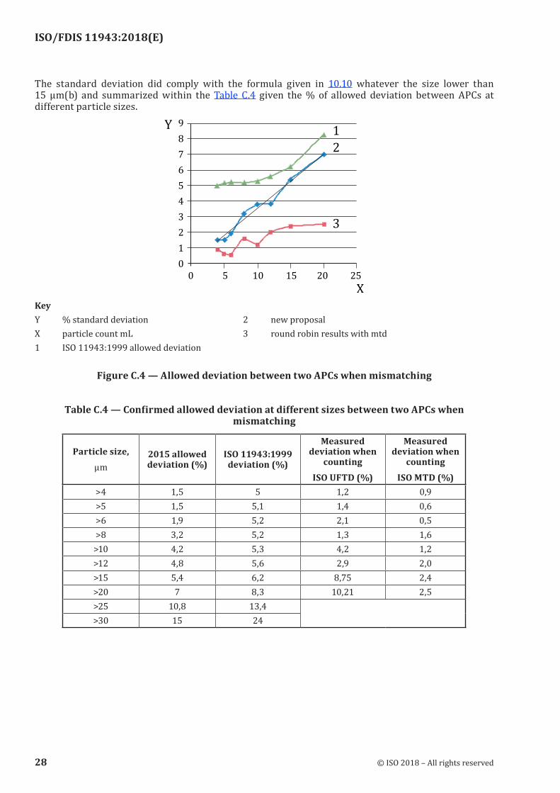
The standard deviation did comply with the formula given in 10.10 whatever the size lower than 15 µm(b) and summarized within the Table C.4 given the % of allowed deviation between APCs at different particle sizes.
KeyY % standard deviation 2 new proposalX particle count mL 3 round robin results with mtd1 ISO 11943:1999 allowed deviation
Figure C.4 — Allowed deviation between two APCs when mismatching
Table C.4 — Confirmed allowed deviation at different sizes between two APCs when mismatching
Particle size,µm
2015 allowed deviation (%)
ISO 11943:1999 deviation (%)
Measured deviation when
countingISO UFTD (%)
Measured deviation when
countingISO MTD (%)
>4 1,5 5 1,2 0,9>5 1,5 5,1 1,4 0,6>6 1,9 5,2 2,1 0,5>8 3,2 5,2 1,3 1,6>10 4,2 5,3 4,2 1,2>12 4,8 5,6 2,9 2,0>15 5,4 6,2 8,75 2,4>20 7 8,3 10,21 2,5>25 10,8 13,4
>30 15 24
28 © ISO 2018 – All rights reserved

ISO/FDIS 11943:2018(E)
Bibliography
[1] ISO 12191, Fluid power systems and components — Graphical symbols and circuit diagrams — Part 1: Graphical symbols for conventional use and data-processing applications
[2] ISO 800001, Quantities and units — Part 1: General
© ISO 2018 – All rights reserved 29

ISO/FDIS 11943:2018(E)
© ISO 2018 – All rights reserved
ICS 23.100.60Price based on 29 pages