Embed Size (px)
Citation preview
Chapter 3. TETRA overview: a
cellular system different from GSM
Chapter 1 provided a brief overview of TETRA along with some of its advantages
and architectural differences over other mobile technologies like GSM. Although a very
rough idea of TETRA’s pros might be extracted out of there, an in-depth analysis must be
carried out in order to justify the need of such technology.
Thus, in this chapter we are going to deal with technical details of the standard,
explaining at length many of the most complex characteristics of the technology, including
logical channels and its internal operation for the two operational modes of TETRA - the
trunked and the direct mode. Along the way GSM will be covered too, but just briefly
since it is a more well-known technology. Due to the extension of the topic many of the
mentioned details have been included in an Appendix A in order to facilitate the read of
the chapter.
The majority of the information given here has been obtained from [7].
3.1 Introduction
A good starting point to get a clear idea of TETRA is to locate the standard in the
OSI model. The well-known model, given in Figure 3.1, is an attempt to break down a big
task into smaller ones, so that a complex issue becomes easier to tackle. This reasoning, of
course, leads to layers.
1
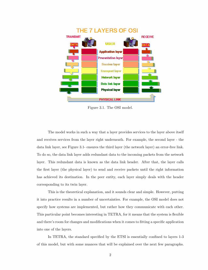
Figure 3.1. The OSI model.
The model works in such a way that a layer provides services to the layer above itself
and receives services from the layer right underneath. For example, the second layer - the
data link layer, see Figure 3.1- ensures the third layer (the network layer) an error-free link.
To do so, the data link layer adds redundant data to the incoming packets from the network
layer. This redundant data is known as the data link header. After that, the layer calls
the first layer (the physical layer) to send and receive packets until the right information
has achieved its destination. In the peer entity, each layer simply deals with the header
corresponding to its twin layer.
This is the theoretical explanation, and it sounds clear and simple. However, putting
it into practice results in a number of uncertainties. For example, the OSI model does not
specify how systems are implemented, but rather how they communicate with each other.
This particular point becomes interesting in TETRA, for it means that the system is flexible
and there’s room for changes and modifications when it comes to fitting a specific application
into one of the layers.
In TETRA, the standard specified by the ETSI is essentially confined to layers 1-3
of this model, but with some nuances that will be explained over the next few paragraphs.
2
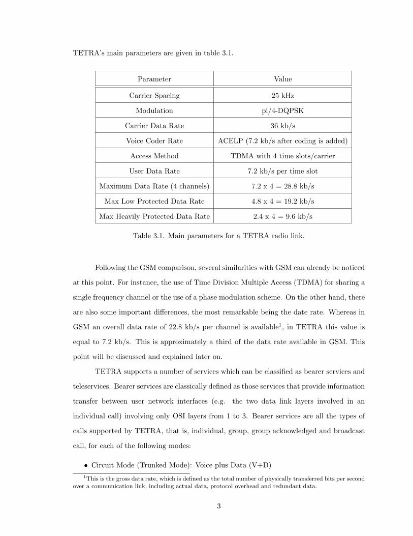
TETRA’s main parameters are given in table 3.1.
Parameter Value
Carrier Spacing 25 kHz
Modulation pi/4-DQPSK
Carrier Data Rate 36 kb/s
Voice Coder Rate ACELP (7.2 kb/s after coding is added)
Access Method TDMA with 4 time slots/carrier
User Data Rate 7.2 kb/s per time slot
Maximum Data Rate (4 channels) 7.2 x 4 = 28.8 kb/s
Max Low Protected Data Rate 4.8 x 4 = 19.2 kb/s
Max Heavily Protected Data Rate 2.4 x 4 = 9.6 kb/s
Table 3.1. Main parameters for a TETRA radio link.
Following the GSM comparison, several similarities with GSM can already be noticed
at this point. For instance, the use of Time Division Multiple Access (TDMA) for sharing a
single frequency channel or the use of a phase modulation scheme. On the other hand, there
are also some important differences, the most remarkable being the date rate. Whereas in
GSM an overall data rate of 22.8 kb/s per channel is available1, in TETRA this value is
equal to 7.2 kb/s. This is approximately a third of the data rate available in GSM. This
point will be discussed and explained later on.
TETRA supports a number of services which can be classified as bearer services and
teleservices. Bearer services are classically defined as those services that provide information
transfer between user network interfaces (e.g. the two data link layers involved in an
individual call) involving only OSI layers from 1 to 3. Bearer services are all the types of
calls supported by TETRA, that is, individual, group, group acknowledged and broadcast
call, for each of the following modes:
• Circuit Mode (Trunked Mode): Voice plus Data (V+D)
1This is the gross data rate, which is defined as the total number of physically transferred bits per secondover a communication link, including actual data, protocol overhead and redundant data.
3

• Packet Connection Oriented Mode
• Packet Connectionless Mode
Therefore, bearer services exclude possible functions associated to end terminals such as
encryption attributes. This types of tasks belong to the teleservices, defined as those ser-
vices that provide the complete capability for communication between users including the
terminal functions. In other words, a teleservices will comprise services from layer 1 to layer
7 of the OSI stack. The teleservices supported by TETRA are voice (either encrypted or
unencrypted) for each of the following calls:
• Individual call
• Group call
• Acknowledged group call
• Broadcast call
Other than this, TETRA has some supplementary services which can be seen as modifica-
tions of the previous but can’t be classified in either type. For example, allocation of access
priority (more commonly known as priority calls) or call forwarding. These aspects of the
standard will be discussed later on.
3.2 Definition and characteristics
It is not an easy task to give a short, clear definition of what is TETRA. As it was
advanced in the first chapter, TETRA is a type of Professional Mobile Radio (PMR)2 that
provides a private group of users (e.g. a company) with a number of services. A PMR is
usually set up by a group of user or a company and includes the whole infrastructure as
well as the mobile stations. Although it’s normally deployed by a company that requires a
private parallel infrastructure to public mobile radio systems like GSM, it can be deployed
for different reasons. For example, it can be often a cheaper solution in the long-term than
2The initial ’P’ can stand for either Private or Professional, and there’s no fixed compromise on this.
4
the usage of GSM. TETRA is also a trunked radio system, which as it was also mentioned
in the introduction means that it’s a computer-controlled system.
Even if this definitions are accurate and true, they do not quite explain what TETRA
provides or what it can be used for. TETRA is more than a mere PMR technology or a
trunked system, and for this reason, the following list has been drawn up in order to put
together everything TETRA is.
• TETRA a 100% digital system, which by the time it was defined, the 90’s, meant an
important step forward to definitely left analogue technologies behind. In addition,
this feature makes the system particularly suitable for IP environments3.
• It’s a set of standards defined by the European Telecommunications Standards Insti-
tute (ETSI). Its specifications are mandatory in Europe and have also been adopted
worldwide in many other places. ETSI is also in charge of updating the standard.
• TETRA was designed to be interoperable with other technologies and easily scalable
in order to provide a flexible solution. The traditional example is a network with a
certain coverage at first which later can be easily expanded/reduced according to its
needs.
• TETRA is the main PMR technology along with TETRAPOL, another PMR system
with similar characteristics. If you put both technologies together, they practically
dominate the entire PMR market.
There are some other important details regarding TETRA. For example, since it’s a private
system, a new infrastructure needs to be deployed to use the technology. This means an
important investment of money and it’s important to bear it in mind.
TETRA OPERATIONAL MODES
Two different operational modes are provided:
• The Circuit Mode, also know as the Trunked Mode, for transmitting both voice and
data (Voice+Data, or V+D). Simply put, in this mode each terminal in the area of
3As a matter of fact, the hardware used in the present project, TETRAFlex R©, is a 100% IP-basedsystem.
5
coverage is allocated a Traffic CHannel (TCH) for the duration of the call, even if the
source is not active. A traffic channel is one of a number of logical channel specified in
the TETRA standard. They are used for managing and maintaining purposes while
the duration of a call. The concept of logical channel is crucial to the operation of the
TETRA system and will be fully addressed later in Section 3.5 and in Appendix A.
• The Direct Mode Operation (DMO), also known as the walkie-talkie mode. Roughly
speaking, it allows users to communicate among each other without actually using the
trunked network. In other words, communication mobile-to-mobile is possible without
intervention of the TETRA network. The implications of this mode will be discussed
in Section 3.6 and Appendix B..
As a matter of fact, there’s a third operational mode defined by TETRA. It is called the
Packet Data Optimised (PDO). It’s the least known due to its lack of commercial use. This
mode is intended to be used only for sending data over a packet switched network, totally
neglecting voice services. Due to voice needs in day-to-day communications, to date no
manufacturer has developed any PDO applications and it’s only used for research purposes.
Interestingly, the work from this standardisation activity has been carried forward
in the Project MESA space - a Partnership Programme between ETSI and TIA.
3.3 TETRA Network Architecture vs GSM’s
Perhaps the best way to obtain a quick, intuitive idea of a new system is to show a
sketch of its architecture. A possible TETRA network architecture is illustrated in Figure
3.2. Why possible? Unlike GSM network architecture given in Figure 3.3, TETRA is
exclusively defined in terms of its interfaces, i.e. the standards defined to communicate
with “the outer world”.
ETSI refers to TETRA networks (in pink) as the Switching and Management Infras-
tructure. This includes the base stations, controllers and all necessary equipment to set up
a TETRA network and allow mobile stations to communicate with/through them.
6
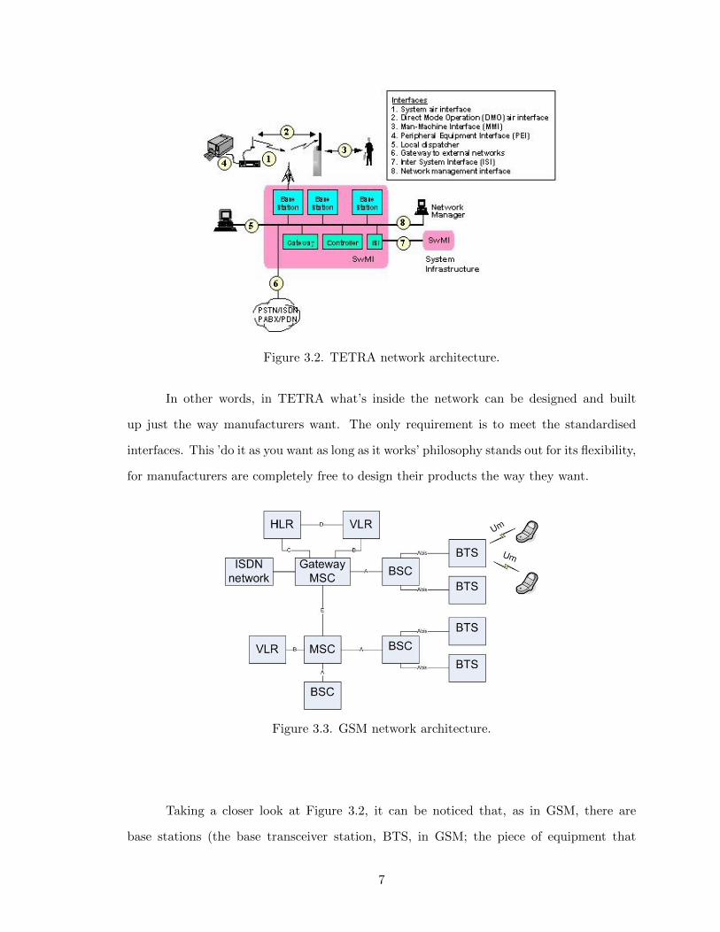
Figure 3.2. TETRA network architecture.
In other words, in TETRA what’s inside the network can be designed and built
up just the way manufacturers want. The only requirement is to meet the standardised
interfaces. This ’do it as you want as long as it works’ philosophy stands out for its flexibility,
for manufacturers are completely free to design their products the way they want.
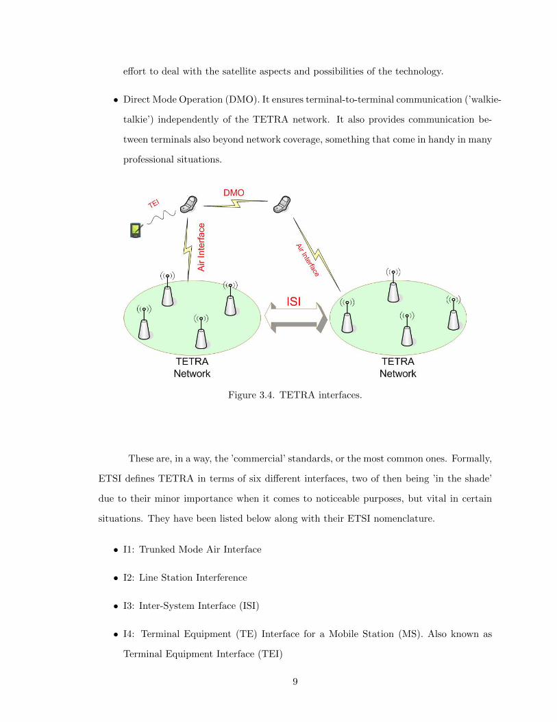
Figure 3.3. GSM network architecture.
Taking a closer look at Figure 3.2, it can be noticed that, as in GSM, there are
base stations (the base transceiver station, BTS, in GSM; the piece of equipment that
7

connects mobile terminals with the network equipment), a base controller (the base station
controller, BSC, in GSM; also regarded as the intelligence behind the BTSs, the piece of
equipment that actually manages the requirements of the terminals present in the cell. The
BSC reports to the switching center), a gateway to control the access to another networks
such as public telephony, Internet, LAN/WAN networks, etc. The switching centers are not
specified, and it is the equipment at the controller along with the central remote TETRA
core network the ones that will take care of their tasks.
The important and key idea in this section is to keep always in mind that the internal
structure in a TETRA network is never standardised; it’s the set of input/output interfaces
what it is indeed standardised, and that’s exactly what it is going to be studied in the next
section.
3.4 TETRA interfaces
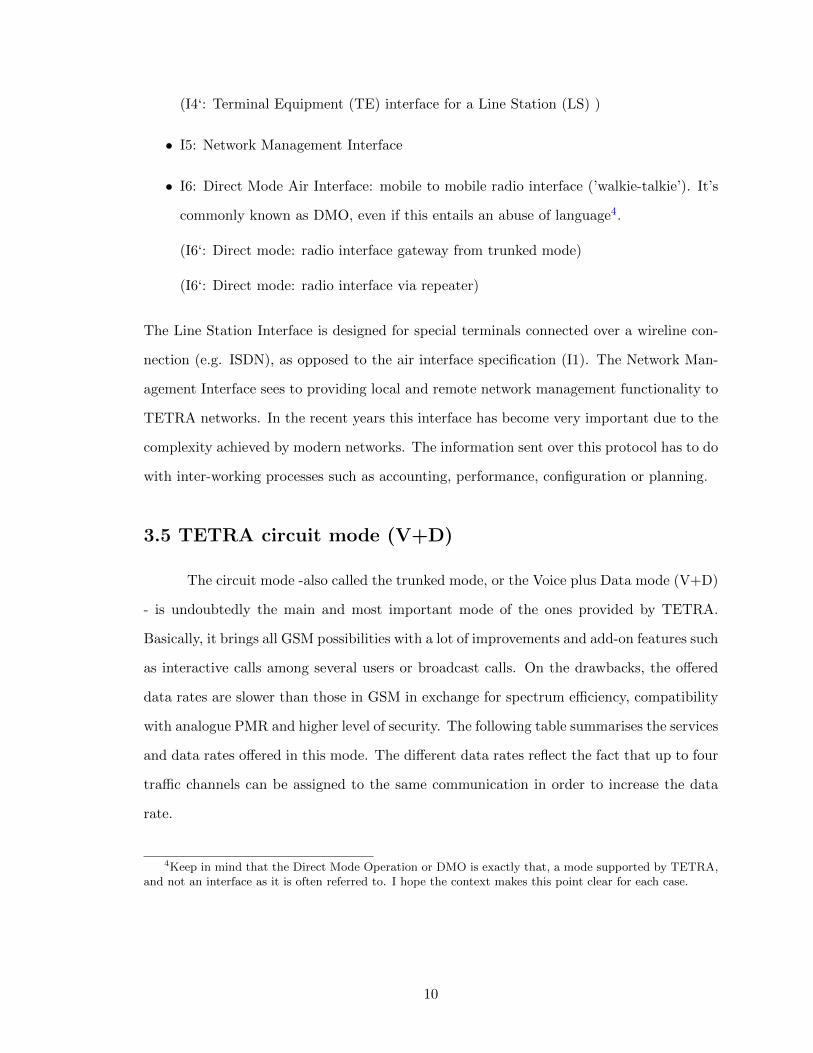
When talking about TETRA interfaces we often refer to the four standards illustrated
in Figure 3.4. The aims of the set are to ensure interoperability, interworking and network
management:
• Air Interface. It standardises the connection between the base station and the radio
terminals. In other words, it ensures interoperability of terminal equipment from
different manufacturers, so that radio terminals can be developed independently with
the certainty that they will be compatible. The air interface is the most complex of
the standards and the hardest to implement.
• Peripheral Equipment Interface (PEI, also known as TEI from Terminal in some
books). This interface standardises the connection between external devices and radio
terminals. The aim of this standard is to facilitate the independent development of
mobile data applications.
• Inter-System Interface (ISI) allows the interconnection of TETRA networks from dif-
ferent manufacturers, that is, it standardises the connection between two base stations.
Speaking of ISI, in the present project it’ll be the main focus of study, making a special
8
effort to deal with the satellite aspects and possibilities of the technology.
• Direct Mode Operation (DMO). It ensures terminal-to-terminal communication (’walkie-
talkie’) independently of the TETRA network. It also provides communication be-
tween terminals also beyond network coverage, something that come in handy in many
professional situations.
Figure 3.4. TETRA interfaces.
These are, in a way, the ’commercial’ standards, or the most common ones. Formally,
ETSI defines TETRA in terms of six different interfaces, two of then being ’in the shade’
due to their minor importance when it comes to noticeable purposes, but vital in certain
situations. They have been listed below along with their ETSI nomenclature.
• I1: Trunked Mode Air Interface
• I2: Line Station Interference
• I3: Inter-System Interface (ISI)
• I4: Terminal Equipment (TE) Interface for a Mobile Station (MS). Also known as
Terminal Equipment Interface (TEI)
9
(I4‘: Terminal Equipment (TE) interface for a Line Station (LS) )
• I5: Network Management Interface
• I6: Direct Mode Air Interface: mobile to mobile radio interface (’walkie-talkie’). It’s
commonly known as DMO, even if this entails an abuse of language4.
(I6‘: Direct mode: radio interface gateway from trunked mode)
(I6‘: Direct mode: radio interface via repeater)
The Line Station Interface is designed for special terminals connected over a wireline con-
nection (e.g. ISDN), as opposed to the air interface specification (I1). The Network Man-
agement Interface sees to providing local and remote network management functionality to
TETRA networks. In the recent years this interface has become very important due to the
complexity achieved by modern networks. The information sent over this protocol has to do
with inter-working processes such as accounting, performance, configuration or planning.
3.5 TETRA circuit mode (V+D)
The circuit mode -also called the trunked mode, or the Voice plus Data mode (V+D)
- is undoubtedly the main and most important mode of the ones provided by TETRA.
Basically, it brings all GSM possibilities with a lot of improvements and add-on features such
as interactive calls among several users or broadcast calls. On the drawbacks, the offered
data rates are slower than those in GSM in exchange for spectrum efficiency, compatibility
with analogue PMR and higher level of security. The following table summarises the services
and data rates offered in this mode. The different data rates reflect the fact that up to four
traffic channels can be assigned to the same communication in order to increase the data
rate.
4Keep in mind that the Direct Mode Operation or DMO is exactly that, a mode supported by TETRA,and not an interface as it is often referred to. I hope the context makes this point clear for each case.
10

TETRA Teleservices
Individual call
Group call
Broadcast call
Acknowledged call
TETRA Bearer Services
Circuit mode protected data 4.8/9.6/14.4/19.2 kb/s
Circuit mode heavily protected data 2.4/4.8/7.2/9.6 kb/s
Connection oriented data packet
Connection data packet
Table 3.2. TETRA bearer services and teleservices.
Previously, it was mentioned that in this mode each mobile terminal is allocated
a traffic channel (TCH) for the duration of a call, irrespective of whether that source is
active or not. A traffic channel is a type of channel called logical channel (logical channels
will be explained in the next paragraphs), often bi-directional, that carries user information.
Different types of traffic channels are defined in TETRA depending on the use. For instance,
there are traffic channels for speech, for data applications and for different data message
speeds.
The ’physical’ transmission mechanism used by logical channels is given by a physical
channel that exists within the physical layer. How exactly? Simply by using a specific carrier
frequency/slot. To avoid any confusion, let’s say now that this does not mean that only one
logical channel can be transmitted through a physical channel, on the contrary; a particular
physical channel can and is used for transmitting several logical channels on a shared basis
by using a multiplexion mechanism: TDMA. Let’s take a closer look at this:
As shown in Fig. 3.5 (next page), each TETRA frame is made up of four time slots,
with a duration of 56.67 ms. This frame is repeated over time up to 18 times to make up
a TETRA multiframe. Each of the columns shown, made up of 18 time slots each, is a
physical channel. To make a long story short, this is how the multiframe goes: in normal
operation, time slot 1 of every frame (both uplink and downlink) is allocated for control
purposes. This is known as the Control Physical channel (CP) (first column). The other
3 time-slots (or channels5) are used for traffic purposes and represent the Traffic Physical
5Note how it exists an abuse of language when it comes to talking about channels. It is important toknow when we refer to logical channels and physical channels, since they are not the same thing. Simply put,a physical channel can carry up to four logical channels (by means of TDMA), and these logical channels
11
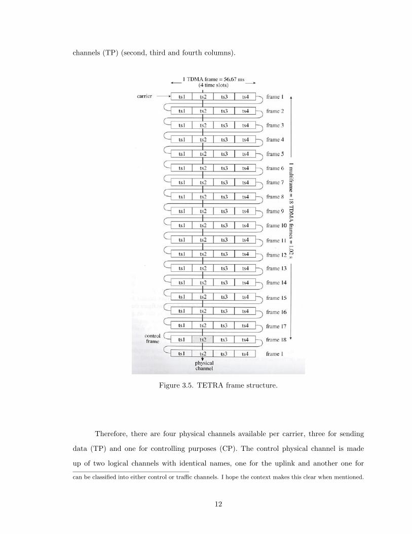
channels (TP) (second, third and fourth columns).
Figure 3.5. TETRA frame structure.
Therefore, there are four physical channels available per carrier, three for sending
data (TP) and one for controlling purposes (CP). The control physical channel is made
up of two logical channels with identical names, one for the uplink and another one for
can be classified into either control or traffic channels. I hope the context makes this clear when mentioned.
12
the downlink in charge of maintenance. The name of this logical channel is Main Control
CHannel (MCCH) and it’ll be often referred to over the next sections since it turns out to
be a key logical channel in TETRA.
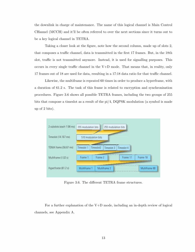
Taking a closer look at the figure, note how the second column, made up of slots 2,
that composes a traffic channel, data is transmitted in the first 17 frames. But, in the 18th
slot, traffic is not transmitted anymore. Instead, it is used for signalling purposes. This
occurs in every single traffic channel in the V+D mode. That means that, in reality, only
17 frames out of 18 are used for data, resulting in a 17:18 data ratio for that traffic channel.
Likewise, the multiframe is repeated 60 times in order to produce a hyperframe, with
a duration of 61.2 s. The task of this frame is related to encryption and synchronisation
procedures. Figure 3.6 shows all possible TETRA frames, including the two groups of 255
bits that compose a timeslot as a result of the pi/4, DQPSK modulation (a symbol is made
up of 2 bits).
Figure 3.6. The different TETRA frame structures.
For a further explanation of the V+D mode, including an in-depth review of logical
channels, see Appendix A.
13
3.6 TETRA Direct Mode Operation
Once a thorough breakdown of the trunked mode has been presented it is time to talk
about the so-called ’walkie-talkie’ feature of TETRA, the Direct Mode Operation (DMO).
The services provided by this mode are drawn up here:
• Individual/group circuit mode calls in simplex mode.
• Call set-up with and without presence check.
• Clear and encrypted circuit mode operation.
• Pre-emption capability.
• User defined short message transmission and reception.
• Pre-defined short message transmission and reception.
The most important things to note are: (a) unlike the trunked mode, the direct mode does
not support duplex transmission, and (b) only voice and short messages (as GSM texts) are
available; data traffic is not supported.
3.6.1 Introduction
The trunked mode, seen at length both in the previous subsection and Appendix
A, involves the utilisation of a number of the interfaces defined in Figure 3.4, all of them
regulated by the ETSI. As it has been detailed, this mode shares a lot of similarities with
GSM in its performance and some of its characteristics. In turn, the direct mode is totally
unknown to GSM. It brings the possibility to directly communicate users among each other
without actually using the TETRA infrastructure itself. This feature offers new advantages,
such as communication between terminals beyond the trunked coverage.
There is a reason why the trunked mode was explained in first place. The TETRA
specifications are written in a way that a mobile terminal operating in the trunked mode
can be contacted by a DMO mobile (that is, a mobile station using the direct mode) as
14
long as it’s located within the mobile-to-mobile range area6. While the vice versa is true,
the first option is much more common.
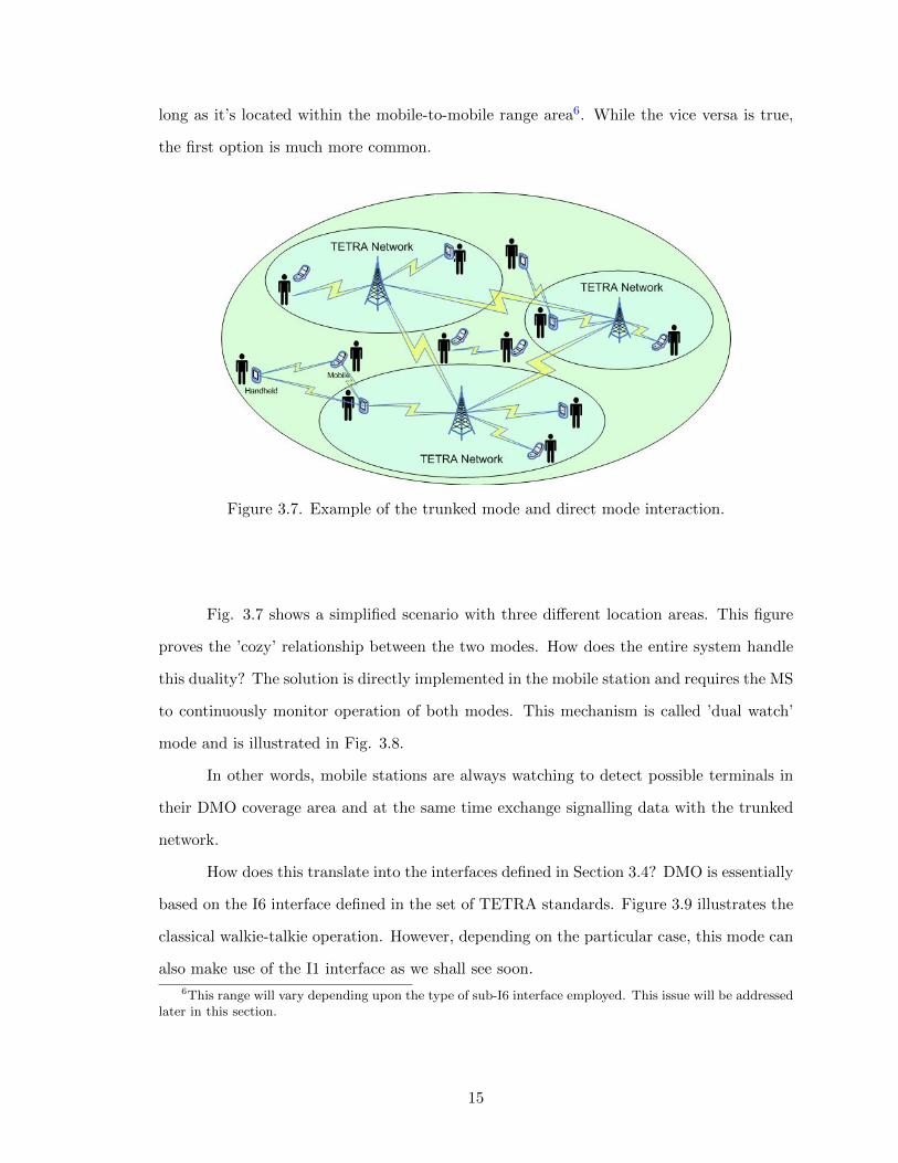
Figure 3.7. Example of the trunked mode and direct mode interaction.
Fig. 3.7 shows a simplified scenario with three different location areas. This figure
proves the ’cozy’ relationship between the two modes. How does the entire system handle
this duality? The solution is directly implemented in the mobile station and requires the MS
to continuously monitor operation of both modes. This mechanism is called ’dual watch’
mode and is illustrated in Fig. 3.8.
In other words, mobile stations are always watching to detect possible terminals in
their DMO coverage area and at the same time exchange signalling data with the trunked
network.
How does this translate into the interfaces defined in Section 3.4? DMO is essentially
based on the I6 interface defined in the set of TETRA standards. Figure 3.9 illustrates the
classical walkie-talkie operation. However, depending on the particular case, this mode can
also make use of the I1 interface as we shall see soon.
6This range will vary depending upon the type of sub-I6 interface employed. This issue will be addressedlater in this section.
15
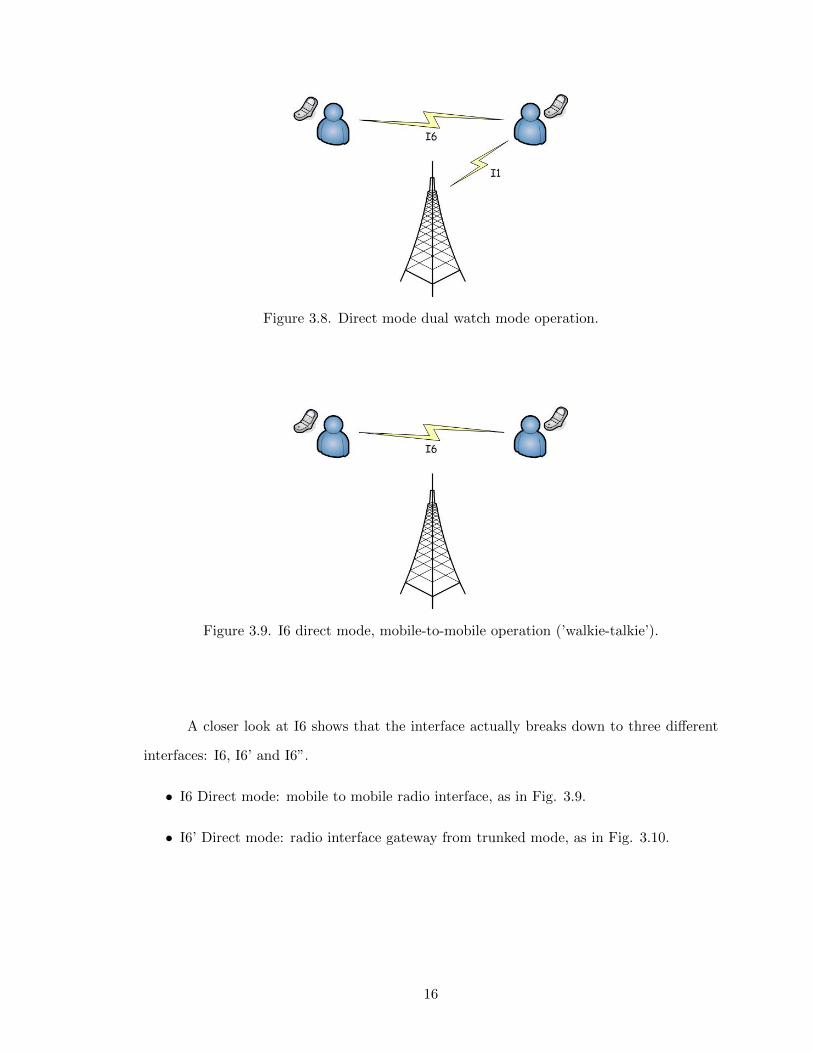
Figure 3.8. Direct mode dual watch mode operation.
Figure 3.9. I6 direct mode, mobile-to-mobile operation (’walkie-talkie’).
A closer look at I6 shows that the interface actually breaks down to three different
interfaces: I6, I6’ and I6”.
• I6 Direct mode: mobile to mobile radio interface, as in Fig. 3.9.
• I6’ Direct mode: radio interface gateway from trunked mode, as in Fig. 3.10.
16
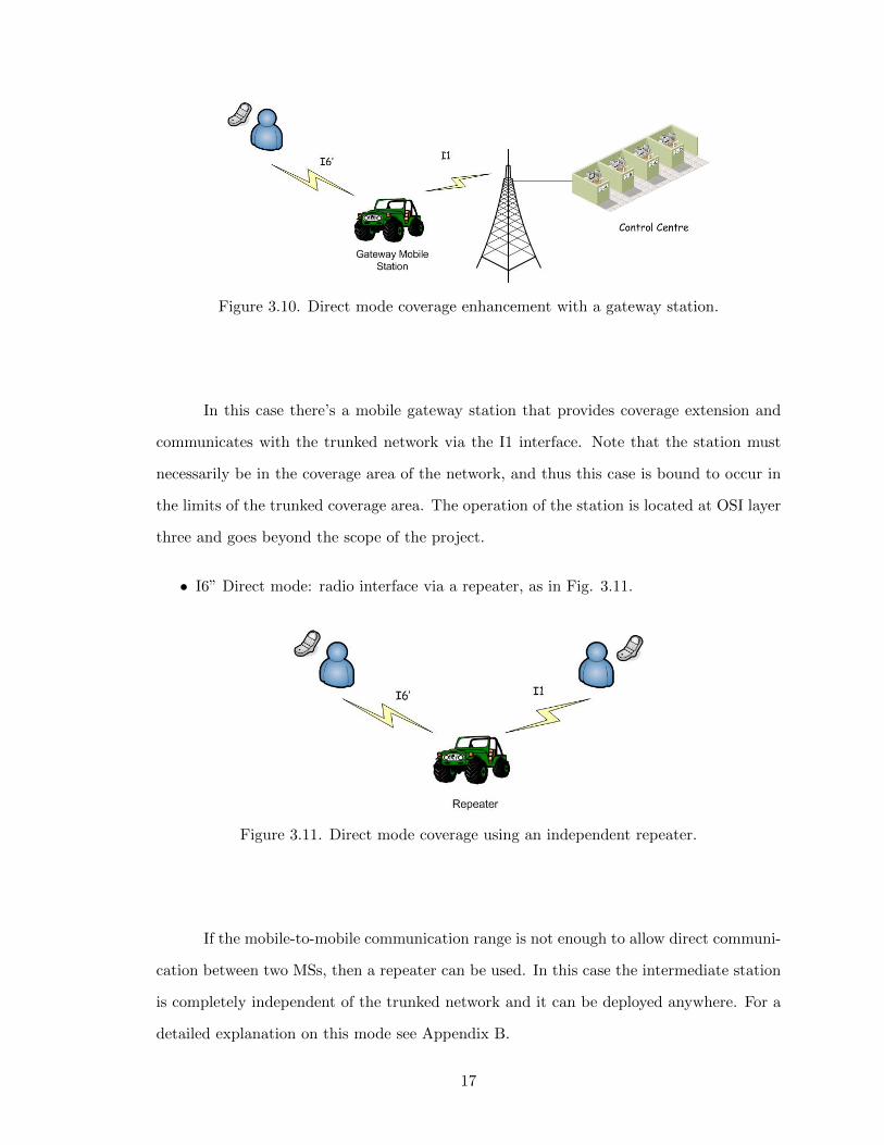
Figure 3.10. Direct mode coverage enhancement with a gateway station.
In this case there’s a mobile gateway station that provides coverage extension and
communicates with the trunked network via the I1 interface. Note that the station must
necessarily be in the coverage area of the network, and thus this case is bound to occur in
the limits of the trunked coverage area. The operation of the station is located at OSI layer
three and goes beyond the scope of the project.
• I6” Direct mode: radio interface via a repeater, as in Fig. 3.11.
Figure 3.11. Direct mode coverage using an independent repeater.
If the mobile-to-mobile communication range is not enough to allow direct communi-
cation between two MSs, then a repeater can be used. In this case the intermediate station
is completely independent of the trunked network and it can be deployed anywhere. For a
detailed explanation on this mode see Appendix B.
17
3.7 TETRA Release 1&2
Everything that has been discussed so far is based on TETRA as we know it today.
This is TETRA Release 1, a deeply rooted standard that has been working for over 15 years
now. However, just like any other technology, it needs to evolve to adapt to new times. In
the words of the TETRA Association:
“TETRA Release 1 (Voice + Data) already provides a very comprehensive portfolio
of services and facilities but as time progresses there is a need to evolve and enhance all tech-
nologies to better satisfy user requirements, future proof investments and ensure longevity.
Like GSM moving to GPRS, EDGE and UMTS/3G, TETRA also needs to evolve to satisfy
increasing user demand for new services and facilities as well as gleaning the benefits of
new technology.”
TETRA release 2 provides the following advantages.
• Trunked Mode Operation (TMO) Range Extension. TETRA’s theoretical extension
in Release 1 is 58 km where in Release 2 goes all the way up to 83 km. This is achieved
by modifying uplink and downlink bursts and guard times, amongst others.
• Adaptive Multiple Rate (AMR) Voice Codec. Just like in GSM, the AMR voice codec
is used to provide the highest quality voice with the lowest data rate.
• Mixed Excitation Liner Predictive, enhanced (MELPe) Voice Codec.
• TETRA Enhanced Data Service (TEDS).
Although TETRA Release 2 is not involved in the present project, it is important
to be aware of its existence.
3.8 Key points of the chapter
• Inputs&Outputs standardised. TETRA’s internal structure is not standardised; only
the interfaces that let devices communicate with the outside are standardised.
• Individual calls exist as in GSM, and in addition there are group, acknowledged and
broadcast calls.
18

• Two different modes: V+D and DMO.
• Direct Mode (’walkie-talkie’ mode). Mobile terminals can communicate even out or
the coverage area.
• Logical channels play a key role in TETRA’s operation.
• Very fast call setup, 300 ms.
• Safer encryption than public mobile services like GSM (end-to-end encryption en-
sured).
• Greater coverage than GSM (theoretically up to 58 km in TETRA release 1 and 83
km in release 2), which can provide a significant cost saving in terms of the necessary
radio infrastructure.
• Voice has always greater coverage than data. Both values depend on the particular
environment.
19