Embed Size (px)
Citation preview

Reference numberISO 17712:2010(E)
© ISO 2010
INTERNATIONAL STANDARD
ISO17712
First edition2010-09-01
Freight containers — Mechanical seals
Conteneurs pour le transport de marchandises — Scellés mécaniques
Licensed to ELC SECURITY PRODUCTS / Mr. CASTROISO Store order #: 10-1158777/Downloaded: 2010-10-14Single user licence only, copying and networking prohibited

ISO 17712:2010(E)
PDF disclaimer This PDF file may contain embedded typefaces. In accordance with Adobe's licensing policy, this file may be printed or viewed but shall not be edited unless the typefaces which are embedded are licensed to and installed on the computer performing the editing. In downloading this file, parties accept therein the responsibility of not infringing Adobe's licensing policy. The ISO Central Secretariat accepts no liability in this area.
Adobe is a trademark of Adobe Systems Incorporated.
Details of the software products used to create this PDF file can be found in the General Info relative to the file; the PDF-creation parameters were optimized for printing. Every care has been taken to ensure that the file is suitable for use by ISO member bodies. In the unlikely event that a problem relating to it is found, please inform the Central Secretariat at the address given below.
COPYRIGHT PROTECTED DOCUMENT © ISO 2010 All rights reserved. Unless otherwise specified, no part of this publication may be reproduced or utilized in any form or by any means, electronic or mechanical, including photocopying and microfilm, without permission in writing from either ISO at the address below or ISO's member body in the country of the requester.
ISO copyright office Case postale 56 • CH-1211 Geneva 20 Tel. + 41 22 749 01 11 Fax + 41 22 749 09 47 E-mail [email protected] Web www.iso.org
Published in Switzerland
ii © ISO 2010 – All rights reserved
Licensed to ELC SECURITY PRODUCTS / Mr. CASTROISO Store order #: 10-1158777/Downloaded: 2010-10-14Single user licence only, copying and networking prohibited
ISO 17712:2010(E)
© ISO 2010 – All rights reserved iii
Contents Page
Foreword ............................................................................................................................................................iv 1 Scope ......................................................................................................................................................1 2 Normative references............................................................................................................................1 3 Terms and definitions ...........................................................................................................................1 3.1 General terms ........................................................................................................................................1 3.2 Terms describing different types of mechanical seals .....................................................................2 4 Seal requirements .................................................................................................................................4 4.1 General and environmental ..................................................................................................................4 4.2 Marking...................................................................................................................................................4 4.3 Identification marks...............................................................................................................................5 4.4 Evidence of tampering ..........................................................................................................................5 5 Testing for seal classification ..............................................................................................................6 5.1 General ...................................................................................................................................................6 5.2 Tensile test .............................................................................................................................................7 5.3 Shear test .............................................................................................................................................12 5.4 Bending test .........................................................................................................................................15 5.5 Impact test............................................................................................................................................17 5.6 Seal classification test report ............................................................................................................19 6 Testing for evidence of tampering.....................................................................................................19 6.1 General .................................................................................................................................................19 6.2 Test apparatus .....................................................................................................................................20 6.3 Test tools..............................................................................................................................................21 6.4 Test methods .......................................................................................................................................21 6.5 Evidence of tampering ........................................................................................................................22 6.6 Test results ..........................................................................................................................................23 Annex A (normative) Seal manufacturers' security-related practices ........................................................24 Annex B (normative) Transition times for requirements of 4.4.3 and Clause 6 .........................................29 Bibliography......................................................................................................................................................31
Licensed to ELC SECURITY PRODUCTS / Mr. CASTROISO Store order #: 10-1158777/Downloaded: 2010-10-14Single user licence only, copying and networking prohibited

ISO 17712:2010(E)
iv © ISO 2010 – All rights reserved
Foreword
ISO (the International Organization for Standardization) is a worldwide federation of national standards bodies (ISO member bodies). The work of preparing International Standards is normally carried out through ISO technical committees. Each member body interested in a subject for which a technical committee has been established has the right to be represented on that committee. International organizations, governmental and non-governmental, in liaison with ISO, also take part in the work. ISO collaborates closely with the International Electrotechnical Commission (IEC) on all matters of electrotechnical standardization.
International Standards are drafted in accordance with the rules given in the ISO/IEC Directives, Part 2.
The main task of technical committees is to prepare International Standards. Draft International Standards adopted by the technical committees are circulated to the member bodies for voting. Publication as an International Standard requires approval by at least 75 % of the member bodies casting a vote.
Attention is drawn to the possibility that some of the elements of this document may be the subject of patent rights. ISO shall not be held responsible for identifying any or all such patent rights.
ISO 17712 was prepared by Technical Committee ISO/TC 104, Freight containers.
This first edition of ISO 17712 cancels and replaces ISO/PAS 17712:2006.
Licensed to ELC SECURITY PRODUCTS / Mr. CASTROISO Store order #: 10-1158777/Downloaded: 2010-10-14Single user licence only, copying and networking prohibited

INTERNATIONAL STANDARD ISO 17712:2010(E)
© ISO 2010 – All rights reserved 1
Freight containers — Mechanical seals
1 Scope
This International Standard establishes uniform procedures for the classification, acceptance and withdrawal of acceptance of mechanical freight container seals. It provides a single source of information on mechanical seals which are acceptable for securing freight containers in international commerce.
NOTE The purpose of mechanical seals is, as part of a security system, to determine whether a freight container has been tampered with, i.e. whether there has been unauthorized entry into the container through its doors. Seals can be effective only if seal users properly select, store, account for, apply, document and attend to seals prior to use and in use; whilst these issues are not addressed in this International Standard, they are relevant to successful use of the seals covered by this International Standard.
Seals that conform to this International Standard are suitable for other applications, such as bulk railcars or truck trailers used in cross-border and domestic operations. Users and regulatory agencies can apply this International Standard to other applications as they deem appropriate.
2 Normative references
The following referenced documents are indispensable for the application of this document. For dated references, only the edition cited applies. For undated references, the latest edition of the referenced document (including any amendments) applies.
ISO/IEC 15417, Information technology — Automatic identification and data capture techniques — Code 128 bar code symbology specification
ISO/IEC 17025, General requirements for the competence of testing and calibration laboratories
3 Terms and definitions
For the purposes of this document, the following terms and definitions apply.
3.1 General terms
3.1.1 seal mechanical device marked with a unique identifier and usually designed for a single use, which is externally affixed to the container doors and designed to evidence tampering or intrusion through the doors of a container and to secure closed doors of a container
NOTE 1 Depending on its design and construction, the seal provides varying degrees of resistance to an intentional or unintentional attempt to open it or to enter the freight container through the container doors.
NOTE 2 Seals need to be designed and constructed so that tamper attempts create and leave evidence of that tampering.
NOTE 3 All grades and types of seals require inspection to indicate whether tampering has occurred or entry has been attempted.
Licensed to ELC SECURITY PRODUCTS / Mr. CASTROISO Store order #: 10-1158777/Downloaded: 2010-10-14Single user licence only, copying and networking prohibited

ISO 17712:2010(E)
2 © ISO 2010 – All rights reserved
3.1.2 high-security seal seal that is constructed and manufactured of material such as metal or metal cable with the intent to delay intrusion
NOTE High-security seals can generally be removed with substantial bolt cutters or cable cutters.
3.1.3 security seal seal that is constructed and manufactured of material that provides limited resistance to intrusion and requires lightweight tools for removal
3.1.4 indicative seal seal that is constructed and manufactured of material that can easily be broken by hand or by using a simple snipping tool or shear
3.1.5 manufacturer company or entity that either owns the seal-producing factory or contracts to buy made-to-order seals for resale from a third party factory
3.1.6 bar code automatic identification technology that encodes information into an array of parallel bars and spaces of varying widths
3.1.7 defeated seal seal which has been opened or removed and replaced or reconstructed without detectable evidence of tampering
3.1.8 tampering attempt to open or remove and then replace or reconstruct a seal without leaving detectable evidence of the attempt
3.1.9 tamper evidence tell-tale indication that an attempt has been made to open or remove and then replace or re-construct without detectable evidence of that attempt
NOTE Examples of tamper evidence include a change in the colour of the material, in surface texture, cracks, indentations, or abrasions. Tamper evident indicators are recognizable by normal examination under the usual circumstances prevailing in practice without technical aids (such as a magnifying glass or microscope).
3.1.10 indicativeness ability to reveal evidence after attempts have been made to tamper with the seal
3.2 Terms describing different types of mechanical seals
3.2.1 wire seal length of wire secured in a loop by some type of seizing device
EXAMPLE Wire seals include: crimp wire, fold wire and cup wire seals.
NOTE The seizing device can be plastic or metal and its deformation is one indication of tampering.
Licensed to ELC SECURITY PRODUCTS / Mr. CASTROISO Store order #: 10-1158777/Downloaded: 2010-10-14Single user licence only, copying and networking prohibited

ISO 17712:2010(E)
© ISO 2010 – All rights reserved 3
3.2.2 padlock seal locking body with a bail attached
EXAMPLE Padlock seals include: wire shackle padlock (metal or plastic body), plastic padlock and keyless padlock seals.
NOTE The padlock itself is not an integral part of the freight container.
3.2.3 strap seal metal or plastic strap secured in a loop by inserting one end into or through a protected (covered) locking mechanism on the other end
NOTE The seizing device can be plastic or metal and its deformation is one indication of tampering.
3.2.4 cable seal cable and a locking mechanism
EXAMPLE On a one-piece seal, the locking or seizing mechanism is permanently attached to one end of the cable. A two-piece cable seal has a separate locking mechanism which slips onto the cable or prefabricated cable end.
3.2.5 bolt seal metal rod, threaded or unthreaded, flexible or rigid, with a formed head, secured with a separate locking mechanism
3.2.6 cinch seal pull-up seal indicative seal consisting of a thin strip of material, serrated or non-serrated, with a locking mechanism attached to one end
NOTE The free end is pulled through a hole in the locking mechanism and drawn up to the necessary tightness. Cinch or pull-up type seals can have multiple lock positions. These seals are generally made of synthetic materials such as nylon or plastic. They can resemble, but are significantly different from, simple electrical ties.
3.2.7 twist seal steel rod or heavy-gauge wire of various diameters, which is inserted through the locking fixture and twisted around itself by use of a special tool
3.2.8 scored seal metal strip which is scored perpendicular to the length of the strip
NOTE The strip is passed through the locking fixture and bent at the score mark. Removal of the seal requires bending at the score mark which results in breakage of the seal.
3.2.9 label seal frangible seal consisting of a paper or plastic backing with adhesive
NOTE The combination of backing and adhesive are chosen to cause the seal to tear when removal is attempted.
3.2.10 barrier seal designed to provide a significant barrier to container entry
NOTE 1 A barrier seal can enclose a portion of the inner locking rods on a container.
NOTE 2 Barrier seals can be designed to be reusable.
Licensed to ELC SECURITY PRODUCTS / Mr. CASTROISO Store order #: 10-1158777/Downloaded: 2010-10-14Single user licence only, copying and networking prohibited

ISO 17712:2010(E)
4 © ISO 2010 – All rights reserved
4 Seal requirements
4.1 General and environmental
4.1.1 The choice of seal for a specific requirement will depend on many factors. It should be selected after full consideration of the user's performance requirements. The first decision is the appropriate seal classification (indicative, security or high security), followed by a decision on a particular type, make and model.
NOTE Selection of a seal presumes the user has already considered the condition of the item to be sealed; some items, such as open rack containers, are not suitable for any seal on the container itself. A seal is only one element in a security system; any seal will only be as good as the system into which it is introduced.
In general terms, a low strength indicative seal should be used where only indication of entry is desired. Where a physical barrier is a definitive requirement either a security or high-security seal should be used.
All seals should be easy to fit correctly on the item to be sealed and once in situ be easy to check for positive engagement of the locking mechanism(s). Correct handling and fitting of seals is at least equal if not greater in importance than selection of the correct seal. A poorly chosen but correctly fitted seal may provide security; however, a well-chosen but incorrectly fitted seal will provide no security.
4.1.2 Security and high-security seals shall be sufficiently durable, strong and reliable so as to prevent accidental breakage and early deterioration (due to weather conditions, chemical action, vibration, shock, etc.) in normal use.
4.1.3 All classes of seals shall be capable of being affixed easily and quickly.
4.1.4 Container seals are typically subjected to the harsh environments of the marine, rail and road transportation industries. Sand and dust, salt spray, grease, snow, ice and grime can be expected to coat the seal. Physical shock and vibration are commonly encountered as a result of handling and transport operations. ISO 18185-3, Freight containers — Electronic seals — Part 3: Environmental characteristics, provides an excellent description of the harsh environment that applies to mechanical seals as well as electronic seals. ISO 18185-3 also provides useful guidelines that are generally applicable to mechanical seals. Mechanical seals shall be constructed to be fit for their intended purposes.
4.1.5 Indicative, security and high-security seals shall be fit for use in the environmental conditions to which maritime containers may be exposed.
4.2 Marking
4.2.1 Seals shall be identified by unique marks (such as a logotype) and unique numbers that are readily legible; markings intended for unique identification of the seal shall be considered permanent. All seals shall be uniquely numbered and identified. The identity of the manufacturer or private label holder shall be evident on every seal, either name or logo.
4.2.2 Seals meeting the relevant criteria shall be marked or stamped in a readily legible way to identify their classification as indicative (“I”), security (“S”), or high-security (“H”) seals. Any modification of markings shall require obvious irreversible physical, chemical, heat or other damage to or destruction of the seal.
4.2.3 Manufacturers or distributors shall not affix such classification marks unless the following two conditions are met.
a) The seal shall meet the appropriate physical parameters and tamper-evident grading in this International Standard, as certified by an accredited testing facility [A.3.3 a)].
b) The firm that manufactures the seal complies with the security-related practices described in Annex A, as certified by an accredited process review organization (A.3.2).
Licensed to ELC SECURITY PRODUCTS / Mr. CASTROISO Store order #: 10-1158777/Downloaded: 2010-10-14Single user licence only, copying and networking prohibited

ISO 17712:2010(E)
© ISO 2010 – All rights reserved 5
4.2.4 In the case of reusable devices, the seal number should be carried on the portion designed to be cut off so as to preclude its reuse.
4.2.5 Seals shall be marked and constructed in such a manner that manufacturers shall be able to identify their own products.
4.2.6 Manufacturers may add a machine-readable bar code to their seals. The bar code shall represent the unique identification numbers as reflected in 4.2.1. Bar codes, if used, shall comply with customer specifications; or, in the absence of a contrary customer specification, the manufacturer shall comply with ISO/IEC 15417, which addresses Code 128 bar code symbology specification.
4.3 Identification marks
Regulatory authorities and private customers may require identifiers that go beyond the requirements of this International Standard, such as in the following cases.
a) Seals intended for use on freight containers moving under customs laws shall be approved or accepted and individually marked as determined by the relevant customs organization or competent authority.
b) If the seal is to be purchased and used by customs, the seal or fastening, as appropriate, shall be marked to show that it is a customs seal by application of unique words or markings designated by the customs organization in question and a unique identification number.
c) If the seal is to be used by private industry (i.e. a shipper, manufacturer or carrier), it shall be clearly and legibly marked and uniquely numbered and identified. It may also be marked with a company name or logo.
4.4 Evidence of tampering
4.4.1 Seals shall be designed and constructed so that tamper attempts create and leave evidence of that tampering. More specifically, seals shall be designed and manufactured to prevent removal or undoing the seal without breaking, or tampering without leaving clear visible evidence, or undetectable re-application of seals designed for single use. Compliant seals shall demonstrate their ability to resist such tamper attempts via the independent tests introduced in 4.4.4.
4.4.2 Seals constructed with plastic coating over metal components shall have sufficiently thick metal components so as to preclude removal of the plastic coating, opening of the seal and re-closing of the seal without leaving visual evidence of tampering.
4.4.3 To preclude the simple removal of a bolt seal by pulling the pin head or locking body through a worn container hasp, the minimum diameter (or minimum widest cross-dimension) for the metal components of a bolt seal shall be 18 mm.
NOTE The seal users who participated in the Working Group for this International Standard were from the international liner shipping industry. They indicated that field personnel experienced recurring problems with 17 mm seals which could be removed intact by pulling the pin head or locking body through worn container hasps. Those members of the Working Group requested that ISO 17712 require an 18 mm minimum diameter for metal parts of bolt seals.
4.4.3.1 The 18 mm minimum shall become effective 18 months after the publication of this International Standard as described in Clause B.2.
NOTE 1 An 18 mm minimum will require engineering, materials and manufacturing changes for most bolt seals. Assuring a smooth, cost-effective and fair transition will require explicit time-phasing and user education. Annex B specifies the bolt seal minimum diameter adoption/obsolescence process.
NOTE 2 In order to reduce the risk of inventory imbalances, seal manufacturers, distributors and users are encouraged to consider the adoption/obsolescence provisions before initiating large production runs or purchases of <18 mm seals.
Licensed to ELC SECURITY PRODUCTS / Mr. CASTROISO Store order #: 10-1158777/Downloaded: 2010-10-14Single user licence only, copying and networking prohibited

ISO 17712:2010(E)
6 © ISO 2010 – All rights reserved
4.4.3.2 Until the 18 mm minimum diameter becomes effective, seals shall be designed and constructed so as not to permit removal without breaking. Once the 18 mm minimum diameter has become effective, all bolt seals shall meet this requirement in order to be ISO 17712 compliant.
The termination of this clause is described in Clause B.3.
NOTE The first sentence of this subclause is adapted from the performance requirement in ISO/PAS 17712:2006, 4.1.3.2.
4.4.4 In order to comply with this International Standard, seals shall pass the tests for evidence of tampering in Clause 6. The testing lab shall be accredited according to ISO/IEC 17025 with an explicit scope that includes this International Standard.
NOTE 6.1 applies the tests of tamper evidence to all classifications of seals (indicative, security and high security).
4.4.5 Different seal types evidence tampering in different ways. It is recommended that users receive training in seal inspection and detection of tampering.
NOTE 1 A useful field and training guide for inspecting seals and detecting tampering is ASTM F1158 “Standard guide for inspection and evaluation of tampering of security seals”.
NOTE 2 Table 5 provides useful examples of tampering evidence.
5 Testing for seal classification
5.1 General
5.1.1 There are four physical test procedures, tensile, shear, bending, and impact. The impact procedure is performed twice at different temperatures. Five samples shall be evaluated for each of the five tests. A total of 25 samples are needed to complete the testing necessary to classify a seal as indicative, security, or high security.
NOTE 1 6.4.2 requires 18 randomly selected seals for the tests of tamper evidence. If one lab performs both the tamper evidence and the strength tests, then a total of 43 seals shall be provided to the lab.
The lowest classification for any sample on any test shall define the classification for the seal being evaluated. To achieve a given classification, all samples must meet the requirements for that classification in all five tests.
NOTE 2 The terms indicative, security and high security refer to the barrier capabilities of the seal (respectively, minimal, medium and meaningful barrier strength). [Since indicative seals, by definition, ‛can easily be broken by hand’ (3.1.4), indicative seals do not need to be subjected to the strength tests in Clause 5.] The classification names do not imply any differences in security against tampering. All three classifications are required to be rated “Pass” in the tests of tamper evidence in Clause 6.
5.1.2 Testing is to be done once every two years as set forth in A.3.3 a) unless more frequent testing is required by the competent authority or there is a meaningful modification in the design or material specifications of the seal.
Seals shall be tested as sold. Test samples shall be selected at random from inventory available for sale.
The general type of seal and its configuration shall be used to determine the appropriate attachment to the test fixture.
Manufacturers shall submit all relevant products to an accredited independent testing laboratory to ensure that the product complies with Clause 6. The testing lab shall be accredited according to ISO/IEC 17025 with an explicit scope that includes this International Standard.
Licensed to ELC SECURITY PRODUCTS / Mr. CASTROISO Store order #: 10-1158777/Downloaded: 2010-10-14Single user licence only, copying and networking prohibited

ISO 17712:2010(E)
© ISO 2010 – All rights reserved 7
5.2 Tensile test
A pull test shall be conducted to determine the strength of a seal's locking mechanism. The test fixture shall apply a uniform load to the seal in a manner that simulates reversal of the motion used to lock the seal. The load shall be slowly applied until the seal forcibly opens or is otherwise broken. For all seals, pulling speed must be (50,8 ± 25,4) mm/min.
The seal shall be classified according to the criteria in Table 1 based on the tensile force recorded at the time of seal failure.
Figures 1 to 5 illustrate the apparatuses for conducting tensile tests; Figures 1 to 4 are required while Figure 5 is suggested.
All tests should be carried out at a temperature of (18 ± 3) °C.
Key 1 shackle fixture: steel, case hardening depth 0,7 mm 2 seal support bolt and nut: steel, class 10.9, see Notes 2, 3 and 4 3 seal location F applied tensile force
NOTE 1 The same seal support fixture is used for the tensile test and the impact test. This seal support fixture (and the bolt seal support fixture in Figure 2) fit into the complete apparatus shown in Figure 11.
NOTE 2 Seal support bolt diameter 6,35 mm (0,25 inches) for seals with smallest cross-sectional dimension less than or equal to 3,18 mm (0,125 inches).
NOTE 3 Seal support bolt diameter 12,7 mm (0,5 inches) for seals with smallest cross-sectional dimension greater than 3,18 mm (0,125 inches).
NOTE 4 Tolerance ±0,254 mm (0,010 inches).
Figure 1 — Tensile test apparatus — Wire seal, strap seal, cable seal, cinch seal
Licensed to ELC SECURITY PRODUCTS / Mr. CASTROISO Store order #: 10-1158777/Downloaded: 2010-10-14Single user licence only, copying and networking prohibited

ISO 17712:2010(E)
8 © ISO 2010 – All rights reserved
Dimensions in millimetres
Key 1 bolt seal support: steel, case hardening depth 0,7 mm 5 4× thread M8 × 1 mm, 20 mm deep 2 shackle fixture: steel, case hardening depth 0,7 mm 6 4× counterbore for M8 × 1 mm 3 bolt seal location 7 1× thread M16 × 1,5 mm thru 4 2× bolt seal support washer: steel, case hardening depth 0,7 mm F applied tensile force
All fasteners used shall be Class 12.9 socket cap-type screws with the specified thread pitch. English substitute fasteners must be Grade 8 and have diameter equal or greater than the specified fastener.
NOTE The same bolt seal support fixture is used for the tensile test and the impact test. The complete apparatus is shown in Figure 11. a The bolt seal support washer (4) thickness may be increased to allow seal clearance, but shall not be less than 5 mm. b Cross-section dimension. c 5 % to 10 % larger than the largest cross-section of the bolt seal shaft.
Figure 2 — Tensile test apparatus — Bolt seals
Licensed to ELC SECURITY PRODUCTS / Mr. CASTROISO Store order #: 10-1158777/Downloaded: 2010-10-14Single user licence only, copying and networking prohibited

ISO 17712:2010(E)
© ISO 2010 – All rights reserved 9
Key 1 twist seal 2 pin, see Notes 1, 2 and 3 F applied tensile force
NOTE 1 Seal support bolt diameter 6,35 mm (0,25 inches) for seals with smallest cross-sectional dimension less than or equal to 3,18 mm (0,125 inches).
NOTE 2 Seal support bolt diameter 12,7 mm (0,5 inches) for seals with smallest cross-sectional dimension greater than 3,18 mm (0,125 inches).
NOTE 3 Tolerance ±0,254 mm (0,010 inches).
a Cross-sectional diameter.
Figure 3 — Tensile test apparatus — Twist seal
Licensed to ELC SECURITY PRODUCTS / Mr. CASTROISO Store order #: 10-1158777/Downloaded: 2010-10-14Single user licence only, copying and networking prohibited

ISO 17712:2010(E)
10 © ISO 2010 – All rights reserved
Key 1 padlock seal 2 pin, see Notes 1, 2 and 3 F applied tensile force
NOTE 1 Seal support bolt diameter 6,35 mm (0,25 inches) for seals with smallest cross-sectional dimension less than or equal to 3,18 mm (0,125 inches).
NOTE 2 Seal support bolt diameter 12,7 mm (0,5 inches) for seals with smallest cross-sectional dimension greater than 3,18 mm (0,125 inches).
NOTE 3 Tolerance ±0,254 mm (0,010 inches).
a Cross-sectional diameter.
Figure 4 — Tensile test apparatus — Padlock seal
Licensed to ELC SECURITY PRODUCTS / Mr. CASTROISO Store order #: 10-1158777/Downloaded: 2010-10-14Single user licence only, copying and networking prohibited

ISO 17712:2010(E)
© ISO 2010 – All rights reserved 11
Key 1 seal support bolt 2 pin F applied tensile force
Figure 5 — Suggested tensile test apparatuses — Other seals
Table 1 — Tensile test seal classification requirements
Load to failure kNa Seal classification
10,0 “H” (high-security seal)
2,27 “S” (security seal)
< 2,27 “I” (indicative seal)
a 1 kN = 225 lbf.
Licensed to ELC SECURITY PRODUCTS / Mr. CASTROISO Store order #: 10-1158777/Downloaded: 2010-10-14Single user licence only, copying and networking prohibited
ISO 17712:2010(E)
12 © ISO 2010 – All rights reserved
5.3 Shear test
5.3.1 A shear test shall be conducted to test the ability of a seal to withstand cutting with shearing blades, as might be implemented with bolt cutters. The cutting blades used in the test fixture shall be sufficiently well aligned that seals are cut and not merely deformed as might occur with a thin, flexible seal and misaligned blades. The compressive load shall be applied until the seal is severed; however, the maximum load shall be limited in accordance with Note 2.
Travel rate for shear test: 12,5 mm ± 6,35 mm/min.
5.3.2 The seal shall be classified according to the criteria in Table 2 based on the compressive load recorded at the time of seal failure and in accordance with Note 3.
Figures 6 and 7 illustrate alternative required apparatus for conducting tensile tests. The apparatus in Figure 7, the shear test bypass apparatus, shall be used for strap, wire and small diameter cable seals. The apparatus in Figure 6 shall be used for all other seals.
When performing the shear test, apply shear force at the weakest section of the seal.
Fixtures shall be designed such that applied stress is within the elastic limit of the fixture material.
Tests shall be carried out at a temperature of 18 °C ± 3 °C.
SAFETY PRECAUTIONS — Do not exceed a shear force of 8 900 N (2 001 lbf). If the specimen has not failed at that force, halt the test and unload the test equipment. Record a shear force of 8 896 N (2 000 lbf). Sudden and violent rupture of the test specimen can endanger personnel, equipment and property.
Table 2 — Shear test seal classification requirements
Load to failure kNa Seal classification
3,336 “H” (high-security seal)
2,224 “S” (security seal)
< 2,224 “I” (indicative seal)
a 1 kN = 225 lbf.
Licensed to ELC SECURITY PRODUCTS / Mr. CASTROISO Store order #: 10-1158777/Downloaded: 2010-10-14Single user licence only, copying and networking prohibited
ISO 17712:2010(E)
© ISO 2010 – All rights reserved 13
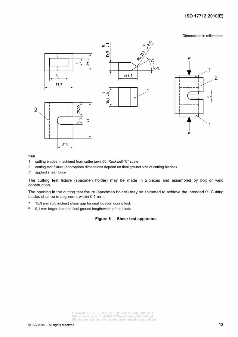
Dimensions in millimetres
Key 1 cutting blades, machined from cutter jaws 60, Rockwell “C” scale 2 cutting test fixture (appropriate dimensions depend on final ground size of cutting blades) F applied shear force
The cutting test fixture (specimen holder) may be made in 2 pieces and assembled by bolt or weld construction.
The opening in the cutting test fixture (specimen holder) may be shimmed to achieve the intended fit. Cutting blades shall be in alignment within 0,1 mm. a 15,9 mm (5/8 inches) shear gap for seal location during test. b 0,1 mm larger than the final ground length/width of the blade.
Figure 6 — Shear test apparatus
Licensed to ELC SECURITY PRODUCTS / Mr. CASTROISO Store order #: 10-1158777/Downloaded: 2010-10-14Single user licence only, copying and networking prohibited

ISO 17712:2010(E)
14 © ISO 2010 – All rights reserved
Dimensions in millimetres
Key 1 special specimen 2 cutting jaw: steel, 60 to 62 Rockwell “C” scale 3 specimen holder: steel, case hardened to 0,7 mm F applied force
This fixture shall be used for cable seals less than 2 mm in diameter and other types of seals too small in cross-section to be effectively sheared by the fixture in Figure 6.
The specimen holder may be made in 2 pieces and assembled by bolt or weld construction.
The opening of the specimen holder may be shimmed to achieve the intended fit. a 0,1 mm larger than the final ground length/width of the blade. b Cross-section dimension. c Minimum 5× smallest cross-section dimension.
Figure 7 — Shear test bypass apparatus — Small diameter cable, wire and strap seals
Licensed to ELC SECURITY PRODUCTS / Mr. CASTROISO Store order #: 10-1158777/Downloaded: 2010-10-14Single user licence only, copying and networking prohibited

ISO 17712:2010(E)
© ISO 2010 – All rights reserved 15
5.4 Bending test
5.4.1 The bending test is conducted to determine the resistance of a seal to failure under bending loads. How the test is run shall be based on the sub classification of the seal as either flexible or rigid. Flexible seals shall be tested for their ability to resist repeated bending cycles without failure. Rigid seals shall be tested to determine their resistance to deformation by bending.
5.4.2 For flexible seals, fix the locking end and flex the material adjacent to this fixed end repeatedly through an arc of 180° until failure or 501 cycles, whichever occurs first. Record the number of cycles through this 180° arc and base classification of the seal on the number of cycles, as shown in Table 3. The bending time (speed) for each cycle of 180° (i.e. duration of bend from −90° to +90°) is (3 ± 1) s.
Tests should be carried out at a temperature of (18 ± 3) °C.
5.4.3 For single-shaft rigid seals, fix the locking end and then fit a tube (300 ± 5) mm long over u 20 mm of the remaining seal and apply a load. The bending time (speed) for each cycle of 90° is (3 ± 1) s. Record the load required to bend the seal and the distance above the fixed end of the seal (the moment arm) that the load is applied. Base the classification of the seal on the maximum bending moment recorded and in accordance with the values given in Table 3.
5.4.4 For rigid seals with two shafts such as in a padlock seal, fix the locking end and then fit a bar or other suitable lever over u 20 mm of the remaining seal and apply a load. Rotate the rod or bar until it is in contact with both shafts. Continue to rotate the bar in the same direction an additional 90°. Record the torsional force needed to achieve the 90° rotation or to cause failure of the locking mechanism if that occurs prior to achieving the 90° rotation. Base the classification of the seal on the maximum bending moment recorded and in accordance with the values given in Table 3. The duration of bending to 90° (speed) is (3 ± 1) s.
Figures 8 to 10 illustrate the required apparatus for conducting bending tests.
Tests should be carried out at a temperature of (18 ± 3) °C.
Key 1 bolt seal 2 movable bolt seal holder 3 holding device (vice or similar object) 4 point of applied load a 90° movement. b Moment arm.
Figure 8 — Bending test apparatus — Bolt seal
Licensed to ELC SECURITY PRODUCTS / Mr. CASTROISO Store order #: 10-1158777/Downloaded: 2010-10-14Single user licence only, copying and networking prohibited
ISO 17712:2010(E)
16 © ISO 2010 – All rights reserved
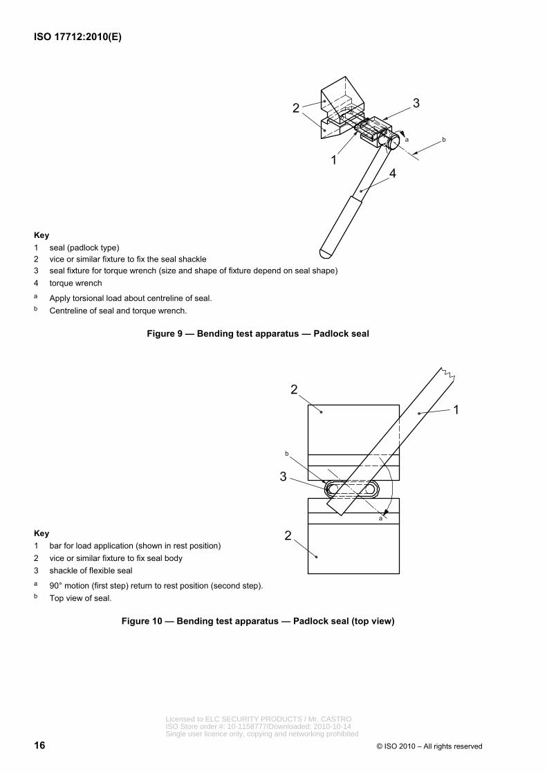
Key 1 seal (padlock type) 2 vice or similar fixture to fix the seal shackle 3 seal fixture for torque wrench (size and shape of fixture depend on seal shape) 4 torque wrench a Apply torsional load about centreline of seal. b Centreline of seal and torque wrench.
Figure 9 — Bending test apparatus — Padlock seal
Key 1 bar for load application (shown in rest position) 2 vice or similar fixture to fix seal body 3 shackle of flexible seal a 90° motion (first step) return to rest position (second step). b Top view of seal.
Figure 10 — Bending test apparatus — Padlock seal (top view)
Licensed to ELC SECURITY PRODUCTS / Mr. CASTROISO Store order #: 10-1158777/Downloaded: 2010-10-14Single user licence only, copying and networking prohibited

ISO 17712:2010(E)
© ISO 2010 – All rights reserved 17
Table 3 — Bending test seal classification requirements
Cycles to failure (flexible seals)
Bending moment to failure (rigid seals)
Nma Seal classification
501 50 “H” (high-security seal)
251 22 “S” (security seal)
< 251 < 22 “I” (indicative seal)
a 1 Nm = 0,737 562 1 ft-lbf.
5.5 Impact test
5.5.1 The impact test shall be conducted to determine the resistance of the seal to an impact load at (18 ± 3) °C and at (−27 ± 3) °C. For the cold test, the test specimen and the test apparatus shall reside in a cold chamber and be chilled completely to the specified temperature. The test shall be conducted in the cold chamber.
The impact load shall be applied five times at a load equivalent to 13,56 J. Subsequent impact test sequences shall be run at a load that is 13,56 J higher than the previous five impact loads. Impacts shall be run until the seal fails or successfully withstands five impacts at 40,68 J. A second set of five seals shall be tested at the second temperature.
The test fixture shall be devised so the impact load is applied at the locking mechanism of the seal in the direction opposite the direction used in locking the seal. The impact test apparatus uses the same bolt seal support fixture as does the tensile test (Figure 2), but it adds a provision for applying impact loads. Figure 10 illustrates the required apparatus for conducting impact tests.
The impact test apparatus shall be placed directly on a solid concrete floor.
SAFETY PRECAUTIONS — Use safety glasses during the test. During impact test parts can become detached which presents an injury risk.
Figure 11 — Impact test apparatus Licensed to ELC SECURITY PRODUCTS / Mr. CASTROISO Store order #: 10-1158777/Downloaded: 2010-10-14Single user licence only, copying and networking prohibited

ISO 17712:2010(E)
18 © ISO 2010 – All rights reserved
Key 1 base plate: aluminum 9 M16 locking nut 2 support tube: “11/2 in” galvanized pipe 10 shackle fixture: steel, case hardening depth 0,7 mm 3 shaft cross support: aluminum 11 bolt seal support: steel, case hardening depth 0,7 mm 4 fixture support: steel 12 bolt seal support washer: steel, case hardening depth 0,7 mm 5 weight guide shaft: steel 13 bolt seal location 6 anvil collar: steel 14 M20 locking nut 7 dead blow weight: steel, (4 ± 0,01) kg 15 2× counterbore for M8 8 adjustable stop collar: steel
All fasteners used shall be Class 12.9 with the specified thread pitch. English substitute fasteners shall be Grade 8 and have a diameter equal or greater than the specified fastener. a Dead blow drop height.
Figure 11 — Impact test apparatus (continued)
Licensed to ELC SECURITY PRODUCTS / Mr. CASTROISO Store order #: 10-1158777/Downloaded: 2010-10-14Single user licence only, copying and networking prohibited

ISO 17712:2010(E)
© ISO 2010 – All rights reserved 19
5.5.2 The seal shall be classified according to the criteria in Table 4 based on the lowest impact load recorded at the time of seal failure. (In order to be classified as high security, all ten test samples must survive five impacts of 40,68 J at high and low temperatures.)
Table 4 — Impact test seal classification requirements
Low temperature impact load, J
High temperature impact load, J
Dead blow mass drop height (see Figure 10)
Seal classification
40,68 40,68 1,037 m “H” (high-security seal)
27,12 27,12 0,691 m “S” (security seal)
< 27,12 < 27,12 0,346 m “I” (indicative seal)
5.6 Seal classification test report
The test report shall contain as a minimum the following information:
a) identification/description of the test specimen;
b) reference to this International Standard;
c) results of the test: (a)..., (b)....... as specified in the individual tests;
d) conditioning, pre-treatment, etc.;
e) temperature and the relative humidity in the test room throughout the test;
f) details of the supply and monitoring equipment and the response criteria;
g) details of any deviation from this International Standard or from the international standards to which reference is made, and details of any operations regarded as optional.
6 Testing for evidence of tampering
6.1 General
This clause requires that compliant seals pass independent tests to demonstrate that tell-tale evidence is generated by attempts to defeat a correctly affixed and closed seal. The fundamental function of any seal is “indicativeness” the ability to reveal evidence after attempts have been made to tamper with the seal. In practical field applications, this calls for evidence available to visual or other inspection of a seal in situ by a commercial or regulatory person.
NOTE 1 Tamper-evident capabilities can result from engineering and design features, methods of construction or a combination of factors.
NOTE 2 Resistance to tampering is another important factor in seal design and manufacture. Since any given security product can be tampered with given sufficient time, motivation and resources, lab-based attempts to measure a seal's time-to-resist tampering have shown little practical value in a standards context.
NOTE 3 Seals are much more vulnerable to successful tampering when they can be manipulated prior to application and closing. Seal designers and manufacturers shall strive to minimize the possibility of easy pre-closure manipulation — that is, before seals are put in place and closed. Pre-application tampering (pre-tampering) generally requires collusion by someone within the supply chain, usually at the shipment's point of origin, before a container is stuffed, closed and sealed. Experience indicates that careful attention to security-related seal procedures is the most effective method to mitigate vulnerability to pre-tampering. It is critical how seals are received by the seal purchaser from the seal manufacturer, how the received seals are stored before they are affixed, and who affixes the seals. These user policy, training and system
Licensed to ELC SECURITY PRODUCTS / Mr. CASTROISO Store order #: 10-1158777/Downloaded: 2010-10-14Single user licence only, copying and networking prohibited

ISO 17712:2010(E)
20 © ISO 2010 – All rights reserved
discipline issues may be addressed by customs administrations and other regulatory bodies as part of the authorization of trading entities to use their own seals in place of customs seals.
6.1.1 Tests for tamper evidence shall provide a pass/fail grade. These tests apply equally to all classifications of seals [indicative (I), security (S) and high security (H)]. While tests of tensile strength, shear resistance, impact resistance and bending are used to establish the strength and barrier classification of a seal, tamper evident performance is expected of all compliant seals, regardless of classification.
A passing grade requires success on three tamper test procedures; some of these procedures require elements of judgment by the testing personnel in addition to technical expertise.
6.1.2 Manufacturers shall submit all relevant products to an ISO or regulatory-accredited independent testing laboratory for tests and certification of conformance. The testing lab shall be accredited according to ISO/IEC 17025 with an explicit scope that includes this International Standard. Seals shall be tested as sold.
6.1.3 Testing for conformance with Clause 6 shall be done once every two years as specified in A.3.3, a) unless more frequent testing is required by the competent authority or there is a meaningful modification in the design or material specifications of the seal.
6.1.4 The effective date for certification of conformance with Clause 6 is 18 months after the publication of ISO 17712. After that date, all ISO 17712-compliant seals must include certification of conformance with Clause 6 (i.e. compliant seals must receive a “Pass” grade on the test of tamper evidence in accordance with 6.6).
NOTE 1 There is a transition delay for Clause 6 testing because tamper testing is a new requirement; testing laboratories, accreditation agencies and manufacturers require time to prepare. Eighteen months will enable the tamper test process to be put in place without unnecessary constraints on trade due to a lack of certified compliant seals. Annex B also addresses the transition period for Clause 6 testing.
NOTE 2 Conformance certificates can be obtained earlier than the effective date, as soon as any laboratory is accredited in accordance with 6.1.2.
6.2 Test apparatus
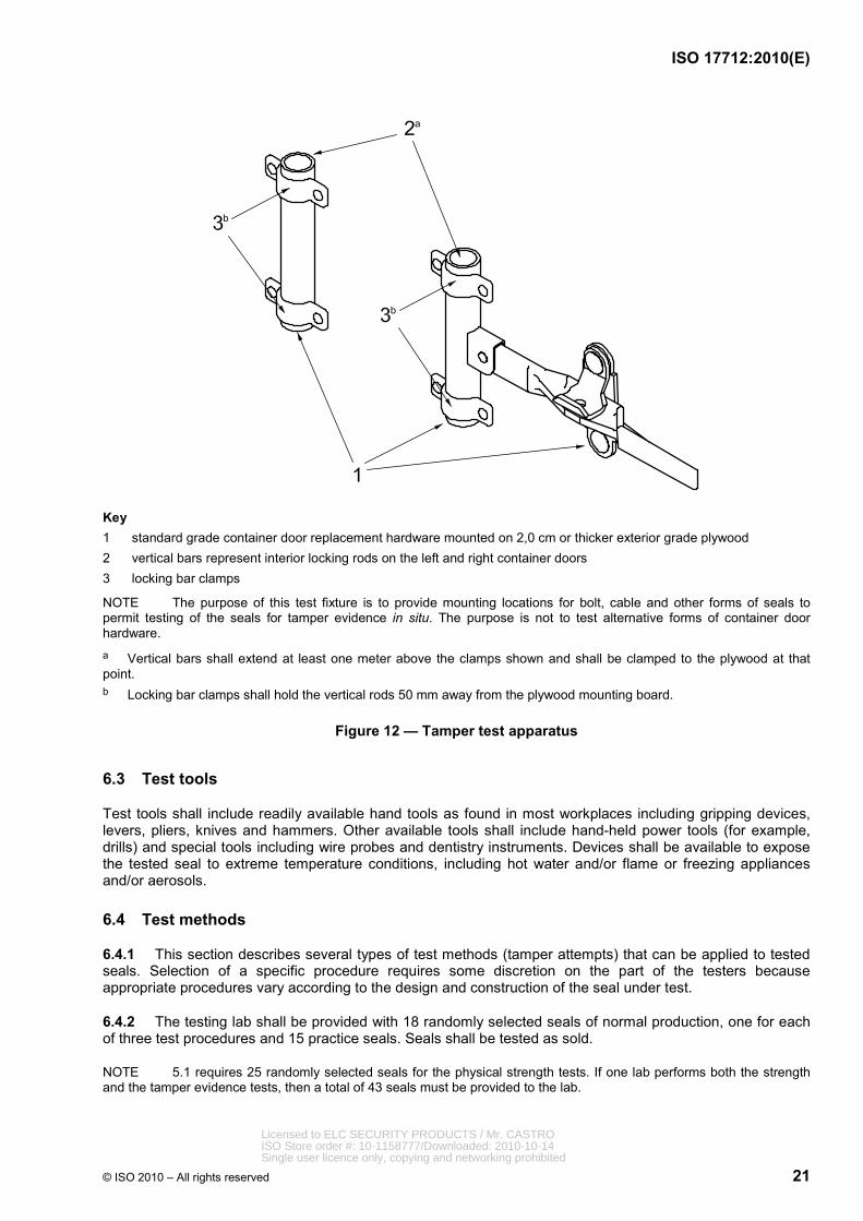
The testing apparatus shall be constructed to represent the container door locking mechanism and conditions that most seals will encounter during normal user operations. Figure 12 reflects a typical situation of medium challenge to a malefactor: a container-on-chassis, with left and right hand door inner locking rods (for cable and similar seals) and a flat vertical surface onto which a shipping container style of door handle will be affixed at a height of approximately 2 m above floor level (for bolt seals). The same apparatus may be used for testing all common types of seals.
NOTE 1 Figure 12 provides for the most common seal locations on the large fleet of containers already in service. Since this location exposes more of the seal to handling and manipulation than more modern container door fastening systems, it is the most demanding location in which to test a seal for tamper evidence. As a result, the same seals will provide a higher level of tamper resistance when applied to container hardware that exposes less of the seal to manipulation. This is the case for all new-build containers, which must meet ISO container design standards, particularly ISO 1496-1.
NOTE 2 The focus of this International Standard is mechanical seals; it does not address the design of the container door fixtures.
Licensed to ELC SECURITY PRODUCTS / Mr. CASTROISO Store order #: 10-1158777/Downloaded: 2010-10-14Single user licence only, copying and networking prohibited
ISO 17712:2010(E)
© ISO 2010 – All rights reserved 21
Key 1 standard grade container door replacement hardware mounted on 2,0 cm or thicker exterior grade plywood 2 vertical bars represent interior locking rods on the left and right container doors 3 locking bar clamps
NOTE The purpose of this test fixture is to provide mounting locations for bolt, cable and other forms of seals to permit testing of the seals for tamper evidence in situ. The purpose is not to test alternative forms of container door hardware. a Vertical bars shall extend at least one meter above the clamps shown and shall be clamped to the plywood at that point. b Locking bar clamps shall hold the vertical rods 50 mm away from the plywood mounting board.
Figure 12 — Tamper test apparatus
6.3 Test tools
Test tools shall include readily available hand tools as found in most workplaces including gripping devices, levers, pliers, knives and hammers. Other available tools shall include hand-held power tools (for example, drills) and special tools including wire probes and dentistry instruments. Devices shall be available to expose the tested seal to extreme temperature conditions, including hot water and/or flame or freezing appliances and/or aerosols.
6.4 Test methods
6.4.1 This section describes several types of test methods (tamper attempts) that can be applied to tested seals. Selection of a specific procedure requires some discretion on the part of the testers because appropriate procedures vary according to the design and construction of the seal under test.
6.4.2 The testing lab shall be provided with 18 randomly selected seals of normal production, one for each of three test procedures and 15 practice seals. Seals shall be tested as sold.
NOTE 5.1 requires 25 randomly selected seals for the physical strength tests. If one lab performs both the strength and the tamper evidence tests, then a total of 43 seals must be provided to the lab.
Licensed to ELC SECURITY PRODUCTS / Mr. CASTROISO Store order #: 10-1158777/Downloaded: 2010-10-14Single user licence only, copying and networking prohibited

ISO 17712:2010(E)
22 © ISO 2010 – All rights reserved
6.4.2.1 The testing lab shall design or define and apply three test procedures for the model of seal under test. Each of the three test procedures will be performed on a single seal that is correctly fitted in accordance with the manufacturer's instructions and in situ on the specified test fixture. No more than one procedure shall be applied to any of the three test specimens.
6.4.2.2 The purpose of the practice seals is to allow lab personnel to probe for vulnerabilities and susceptibility to manipulation and to design their test procedures in advance.
Lab personnel shall utilize three to five practice seals prior to each test. Lab personnel shall identify and retain practice seals.
Labs need not use all practice seals.
6.4.2.3 In exceptional circumstances, when lab personnel have reason to question the consistency of a seal's performance during a formal test with their experience on the practice seals, the lab may repeat the test procedure once on one additional seal drawn from the remaining practice seals.
Accredited labs shall establish written instructions for testing personnel on how to recognize “exceptional circumstances”.
In all cases of exceptional circumstances (that is, for all re-tests), lab personnel shall document their rationale and actions.
NOTE If lab personnel are concerned about the possible occurrence of an exceptional circumstance on the third test procedure, it is incumbent upon them to keep one practice seal in reserve.
6.4.3 Testers may use single tools or a combination of tools and procedures to attempt to disengage, damage, separate, or manipulate the locking action of the seal. The goal of each procedure will be to allow the seal to be opened and re-closed without leaving evidence of the tamper action detectable upon visual inspection.
Similarly, attempts may be made to disassemble the seal and rebuild it to allow re-closure either with original parts, commonly available replica parts or with the use of substitute parts previously disassembled from a practice seal of the same type and design, again without leaving evidence of the action detectable upon visual inspection.
Other examples of tamper test approaches are spinning of bolt heads, using probes to release the locking body's grip in the pin, and trying to replace a removed head or bolt with another that has an altered ID number.
Testers shall perform three different tamper attempts for each seal. Testers shall choose the specific procedures based on the type and design of the seal. No more than one procedure shall be applied to any of the test specimens.
NOTE 1 Detailed test procedures are not enumerated for two reasons. Firstly, prudence about seal security argues against publishing detailed tampering illustrations for potential malefactors in an International Standard. Secondly, it is not feasible to provide tailored procedures for the wide variation of seal design and construction details.
NOTE 2 The absence of detailed tamper test specifications in this International Standard and the discretion entrusted to the testing personnel create a special challenge and responsibility. Certified laboratories need to balance the requirements of conducting meaningful tests and maintaining a consistent degree of difficulty across test subjects. Lab technicians will accumulate experience as they conduct more tests; they need to develop sufficient skill so that early tests are meaningful yet assure that later test subjects do not face more severe test standards simply because their tests happen later. Accrediting agencies are encouraged to address how labs under review manage this challenge.
6.5 Evidence of tampering
After the tamper attempt, a tested seal shall be inspected for evidence of tampering. The tested seal shall be subjected to close visual examination; the initial inspection on all types of seal should be to pull the seal by hand, using a twisting action, in the direction opposite to the locking action. Tamper evident features on seals
Licensed to ELC SECURITY PRODUCTS / Mr. CASTROISO Store order #: 10-1158777/Downloaded: 2010-10-14Single user licence only, copying and networking prohibited
ISO 17712:2010(E)
© ISO 2010 – All rights reserved 23
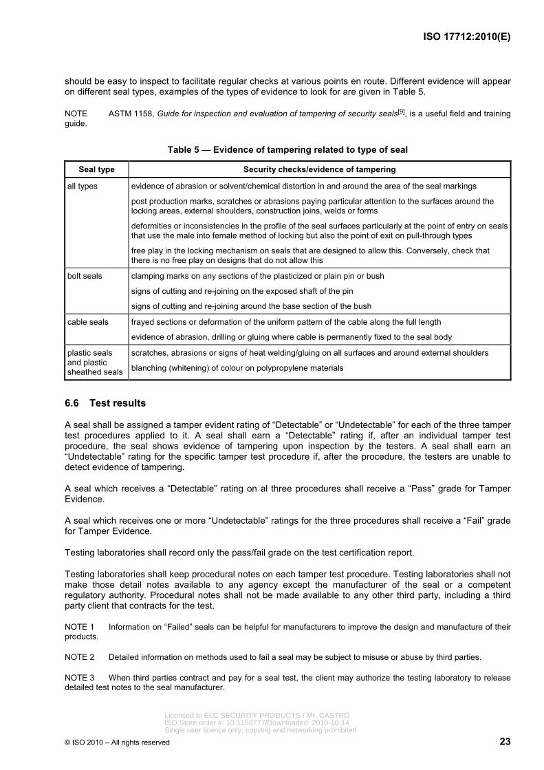
should be easy to inspect to facilitate regular checks at various points en route. Different evidence will appear on different seal types, examples of the types of evidence to look for are given in Table 5.
NOTE ASTM 1158, Guide for inspection and evaluation of tampering of security seals[9], is a useful field and training guide.
Table 5 — Evidence of tampering related to type of seal
Seal type Security checks/evidence of tampering
all types evidence of abrasion or solvent/chemical distortion in and around the area of the seal markings
post production marks, scratches or abrasions paying particular attention to the surfaces around the locking areas, external shoulders, construction joins, welds or forms
deformities or inconsistencies in the profile of the seal surfaces particularly at the point of entry on seals that use the male into female method of locking but also the point of exit on pull-through types
free play in the locking mechanism on seals that are designed to allow this. Conversely, check that there is no free play on designs that do not allow this
bolt seals clamping marks on any sections of the plasticized or plain pin or bush
signs of cutting and re-joining on the exposed shaft of the pin
signs of cutting and re-joining around the base section of the bush
cable seals frayed sections or deformation of the uniform pattern of the cable along the full length
evidence of abrasion, drilling or gluing where cable is permanently fixed to the seal body
plastic seals and plastic sheathed seals
scratches, abrasions or signs of heat welding/gluing on all surfaces and around external shoulders
blanching (whitening) of colour on polypropylene materials
6.6 Test results
A seal shall be assigned a tamper evident rating of “Detectable” or “Undetectable” for each of the three tamper test procedures applied to it. A seal shall earn a “Detectable” rating if, after an individual tamper test procedure, the seal shows evidence of tampering upon inspection by the testers. A seal shall earn an “Undetectable” rating for the specific tamper test procedure if, after the procedure, the testers are unable to detect evidence of tampering.
A seal which receives a “Detectable” rating on al three procedures shall receive a “Pass” grade for Tamper Evidence.
A seal which receives one or more “Undetectable” ratings for the three procedures shall receive a “Fail” grade for Tamper Evidence.
Testing laboratories shall record only the pass/fail grade on the test certification report.
Testing laboratories shall keep procedural notes on each tamper test procedure. Testing laboratories shall not make those detail notes available to any agency except the manufacturer of the seal or a competent regulatory authority. Procedural notes shall not be made available to any other third party, including a third party client that contracts for the test.
NOTE 1 Information on “Failed” seals can be helpful for manufacturers to improve the design and manufacture of their products.
NOTE 2 Detailed information on methods used to fail a seal may be subject to misuse or abuse by third parties.
NOTE 3 When third parties contract and pay for a seal test, the client may authorize the testing laboratory to release detailed test notes to the seal manufacturer.
Licensed to ELC SECURITY PRODUCTS / Mr. CASTROISO Store order #: 10-1158777/Downloaded: 2010-10-14Single user licence only, copying and networking prohibited

ISO 17712:2010(E)
24 © ISO 2010 – All rights reserved
Annex A (normative)
Seal manufacturers' security-related practices
A.1 Introduction
This annex addresses security-related practices relevant to the manufacture and distribution of seals that conform to this International Standard.
The structure of this International Standard reflects the six stages in the life of a freight container seal, as shown in Table A.1. Since this International Standard is about the security-related practices of seal manufacturers, the focus within each stage is on the actions within the purview of those manufacturers.
“Manufacturer”, as used in this annex, refers to the company responsible for the design of the product and driving the process of bringing the product to the market. When that company owns and operates one or more producing factories for seals, then the company headquarters and all its seal producing factories shall be covered within the term “manufacturer.” When the company does not own the producing factory and subcontracts the seal production, “manufacturer” still refers to the driving company and not to the operator/owner of the “xyz” factory.
In order to demonstrate conformance to this annex, manufacturers shall have a timely audit completed by an independent process certification provider specifically accredited to audit conformance with ISO 17712.
NOTE Manufacturers might find it convenient to have audits for ISO 17712 performed at the same time and by the same provider that performs its audit for ISO 9001.
Table A.1 — Six stages in the life of a freight container seal
Stage number
Stage name Role of seal manufacturers
1 design process total responsibility
2 manufacturing total responsibility
3 distribution shall set security-related performance expectations for distributors and resellers.
shall help educate distributors and re-sellers.
4 user knowledge and discipline shall help educate users in the care of seals prior to their application to containers, trailers, or other receptacles.
shall help educate users in correct use of seals.
5 in-transit management may help users and regulators educate supply chain personnel.
6 after-life total responsibility for maintaining data on production, sales, and IDnumbers of seals.
shall help educate distributors and re-sellers about maintaining historical data on their seal inventories and sales.
have no role in maintaining chain-of-custody information on completed cargo shipments
Licensed to ELC SECURITY PRODUCTS / Mr. CASTROISO Store order #: 10-1158777/Downloaded: 2010-10-14Single user licence only, copying and networking prohibited

ISO 17712:2010(E)
© ISO 2010 – All rights reserved 25
A.2 Manufacturer security-related practices in stage 1, design process
a) Manufacturers shall design and classify the physical performance characteristics of seals in accordance with this International Standard. The body of the standard establishes uniform procedures for classification of mechanical seals for freight containers. The specification defines physical parameters for different levels of a seal's physical performance – indicative seals, security seals, and high-security seals.
b) Although the scope of ISO/TC 104 is freight containers, seals that conform to this International Standard are suitable for other applications, such as bulk railcars or truck trailers used in cross-border and domestic operations. Users and regulatory agencies may apply this International Standard to other applications as they deem appropriate.
c) Manufacturers shall “design-in” effective tamper resistance and tamper evidence for all their seal products in conformance with Clause 4.
A.3 Manufacturer security-related practices in stage 2, manufacturing
A.3.1 General
This clause describes the security-related practices to be applied by seal manufacturers during stage 2.
There are two dimensions to certification under A.3. The first addresses the security-related business processes of the manufacturer (in A.3.2). The second addresses the physical properties of the seals themselves (in A.3.3).
A.3.2 Seal manufacturer certification
a) Seal manufacturers shall maintain an ISO 9001 (or equivalent) quality system at all company-owned manufacturing facilities for all processes connected with seals. Additional confidence can be achieved through certification.
b) When purchasing contract production services for market-ready seal products, manufacturers should purchase from plants that maintain an ISO 9001 (or equivalent) quality system.
c) If a manufacturer's facility or outside production facility for market-ready seal products fails to maintain an ISO 9001 (or equivalent) system, notification shall be sent to the appropriate customs administrations and other appropriate regulatory bodies.
d) The security practices referenced herein shall be implemented in accordance with this International Standard.
e) Manufacturers shall accept random and unannounced inspections of facilities and documentation for certification of conformance with this annex; inspections are to be accomplished by accredited third-party certification bodies. The scope of accreditation of these bodies shall include this International Standard.
NOTE The “certification bodies” may include competent governmental agencies or authorities. Nothing in this International Standard implies that industry certifying or regulatory bodies would reveal trade secrets or proprietary information among competitors.
f) Manufacturers shall conduct an initial security risk assessment of facilities, and periodic update reviews, and implement countermeasures and/or policies to overcome potential vulnerabilities or threats.
g) Manufacturers shall assign responsibility for security and product integrity to knowledgeable individual(s), with a principal point of contact.
h) Manufacturers shall agree to cooperate with relevant law enforcement officials.
Licensed to ELC SECURITY PRODUCTS / Mr. CASTROISO Store order #: 10-1158777/Downloaded: 2010-10-14Single user licence only, copying and networking prohibited

ISO 17712:2010(E)
26 © ISO 2010 – All rights reserved
i) Manufacturers shall cooperate with regulatory and certification bodies in responding to questions and issues regarding compliance, irregularities, copying, etc.
j) Manufacturers shall develop and maintain a crisis management strategy to prepare for and respond to tampering and other malicious, criminal, or terrorist actions; the strategy shall provide guidelines to segregating and securing affected product.
k) Manufacturers shall promote seal security awareness among all staff. Security awareness includes identification of whom in management they should alert about potential security problems (24-hour contacts).
l) Manufacturers shall require background checks on all employees to the extent allowed under local law or regulation.
A.3.3 Seal product certification
a) In accordance with Clauses 5 and 6, manufacturers shall submit all relevant products to an accredited independent testing laboratory to ensure that the product complies with this International Standard. The testing lab shall be accredited according to ISO/IEC 17025 with an explicit scope that includes this International Standard.
b) Manufacturers shall mark seals with their company identity.
c) Manufacturers shall produce seals with unique numbers and identifiers. Manufacturers shall not re-use or duplicate these unique seal numbers or identifiers unless authorized by the bona fide user for the specific seal application.
d) Manufacturers shall track the physical identifiers of all seals and related products that they produce or have produced for them. Manufacturers shall record, by seal type, the number and identifier, date of finished production, date of order, date seals were shipped, and names of consignee(s). Manufacturers shall retain this information for a period of at least 7 years in a manner that makes it readily available upon request by a regulatory or certification body.
e) Manufacturers shall restrict the distribution of custom-designed seal application and/or removal tools to facilities authorized by the bona fide user.
f) Manufacturers shall segregate and render non-functional any incidental production of scrap seal product before disposal.
g) Manufacturers shall control access to production and storage areas and loading docks and stores seals and related devices in secure areas.
h) Manufacturers shall lock all loaded trailers or containers on the premises.
i) Manufacturers shall perform inspections to confirm their security expectations by verifying driver identification, if applicable, and verifying the load and count of inbound seal components.
j) Manufacturers shall implement a policy for off-hour deliveries to ensure prior notice of these deliveries. The policy will require the presence of an authorized individual to receive these shipments. Advance notification, by phone, fax, or e-mail, should be required from all vendors/suppliers for incoming deliveries.
A.4 Manufacturer security-related practices in stage 3, distribution
Sales organizations such as distributors or resellers can enhance or undermine even the best manufacturer's security program. The manufacturer shall help educate their distributors and resellers about the importance, mutual advantage, and specifics of effective seal security programs.
Licensed to ELC SECURITY PRODUCTS / Mr. CASTROISO Store order #: 10-1158777/Downloaded: 2010-10-14Single user licence only, copying and networking prohibited

ISO 17712:2010(E)
© ISO 2010 – All rights reserved 27
The manufacturer shall set guidelines and should undertake to ensure that their distributors and resellers comply with the following security-related guidelines.
a) Distributor/reseller shall permit manufacturer to review its security procedures.
b) Manufacturers, if they become aware of a gap in distributor/reseller security practices, shall identify that gap and recommend needed changes that will provide seals and related devices with the necessary oversight and accountability.
c) Distributors/resellers shall not sell seals or related devices without the manufacturer's identity marked on the devices.
d) Distributors/resellers shall record all aspects of a seal shipment, including source, seal numbers and identifiers, description and the name and address of the individual placing the order and the consignee for the order. Distributor/reseller shall retain such records for a period of at least 7 years. Upon request from a government regulatory agency, the distributor/reseller shall make the necessary records available to assist the agency in the investigation of a cargo shipment incident.
e) Distributors/resellers shall conduct an initial security risk assessment of its facilities and implement countermeasures and/or policies to overcome potential vulnerabilities or threats.
f) Distributor/reseller shall control access to storage areas and loading docks, and store seals and related devices in secure areas.
g) Distributor/reseller shall lock all loaded trailers or containers on the premises.
h) Distributor/reseller shall “inspect what it expects”, by verifying driver identification, if applicable, and verifying the load and count of inbound seal components.
i) Distributor/reseller shall implement a policy for off-hour deliveries to ensure prior notice of these deliveries. The policy will require the presence of an authorized individual to receive these shipments. Advance notification, by telephone, facsimile transmission, or email, should be required from all vendors/suppliers for incoming deliveries.
A.5 Manufacturer security-related practices in stage 4, user knowledge and discipline
This stage focuses upon the security-related practices of bona fide users, including government agencies, such as customs administrations that might apply seals to a container shipment. The influence and responsibility of seal manufacturers in stage 4 is limited to education.
Security-related practices, in this instance, can be enhanced by the seal manufacturer through the inclusion of educational information about seals on product cartons, product literature, the Internet, and on-site training when appropriate.
a) Manufacturers shall help educate users in the importance of proper control of and record-keeping about seals prior to their application and use.
b) Manufacturers shall help educate users in correct and most effective use of seals, including conformance with applicable standards and regulations.
Licensed to ELC SECURITY PRODUCTS / Mr. CASTROISO Store order #: 10-1158777/Downloaded: 2010-10-14Single user licence only, copying and networking prohibited

ISO 17712:2010(E)
28 © ISO 2010 – All rights reserved
A.6 Manufacturer security-related practices in stage 5, in-transit management
In-transit shipment chain-of-custody falls beyond the responsibility of the seal manufacturer. However, manufacturers may help users and regulators educate supply chain personnel.
Such education involves the application of chain-of-custody principles. Such principles may include assuring that bar code readers, where applicable, are functioning, that the seal is the right type, that its number has been documented and verified, that its application is correct, and that an audit trail is established. In addition, the principles may include a seal anomaly policy, such as procedures to follow if tampering is noted during a shipment.
A.7 Manufacturer security-related practices in stage 6, after-life
Most of the post-shipment stage in the life cycle of a seal relates to maintaining chain-of-custody information about the shipment of goods itself. Seal manufacturers have no role in maintaining chain-of-custody information on completed cargo shipments.
Manufacturers' responsibilities and security-related practices relate to data about the seals themselves. These responsibilities and practices are covered in stages 2, 3 and, to a lesser extent, 4. Manufacturers retain
a) total responsibility for maintaining the manufacturer's data on seal production, sales, and unique numbers and identifiers, and
b) responsibility to educate distributors and re-sellers about maintaining historical data on their seal inventories and sales.
Licensed to ELC SECURITY PRODUCTS / Mr. CASTROISO Store order #: 10-1158777/Downloaded: 2010-10-14Single user licence only, copying and networking prohibited

ISO 17712:2010(E)
© ISO 2010 – All rights reserved 29
Annex B (normative)
Transition times for requirements of 4.4.3 and Clause 6
B.1 Introduction
Two clauses of this International Standard have deferred effective dates (transition times) following its publication.
⎯ Subclause 4.4.3 addresses the minimum diameter (or minimum widest cross-dimension) for the metal components of bolt seals.
⎯ Clause 6 addresses testing for tamper evidence.
The purpose of this annex is assist users of this International Standard by clarifying normative transition requirements and related informative guidance in a single location. All normative statements in this annex are restatements of requirements in the numbered clauses of this International Standard; should there be a discrepancy, the requirements in the numbered clauses are definitive.
NOTE Another purpose of this annex and the relevant text in the body of the standard is to prescribe a transition process that is cost-effective, fair and timely for all stakeholders.
B.2 Minimum diameter of bolt seals
Subclause 4.4.3 establishes the minimum diameter (or minimum widest cross-dimension) for the metal components of a bolt seal as 18 mm. ISO/PAS 17712 set a performance requirement that seals could not be pulled through a container hasp without breaking. Common practice in the seal industry has been a 17 mm minimum diameter. Regardless, transition to 18 mm is likely to require design, engineering, materials and production changes to comply with 4.4.3.
The transition addresses an 18 mm gradual adoption process and a corresponding gradual obsolescence process for the ISO/PAS 17712 performance requirement.
B.2.1 18 mm diameter gradual adoption process
The effective date for the requirements of 4.4.3 for 18 mm minimum diameter metal components of bolt seals is 18 months from the date of publication of this International Standard. As of that date, manufacturers of compliant seals shall possess ISO 17712 test certifications for seal models in accordance with A.3.3 a).
Manufacturers may obtain certifications and market 18 mm-compliant seals prior to that date.
B.2.2 Gradual obsolescence process for ISO/PAS 17712 performance requirements
Seals that do not comply with 4.4.3 but do comply with the performance requirement in 4.4.3.2 shall be considered compliant with this International Standard until 18 months after its date of publication.
No test certification will be valid after that date without certification of compliance with 4.4.3 (18 mm). Unused inventory of 4.4.3.2 compliant but 4.4.3 non-compliant seals shall not be represented as ISO 17712 compliant.
Licensed to ELC SECURITY PRODUCTS / Mr. CASTROISO Store order #: 10-1158777/Downloaded: 2010-10-14Single user licence only, copying and networking prohibited

ISO 17712:2010(E)
30 © ISO 2010 – All rights reserved
B.3 Testing for evidence of tampering
Clause 6 establishes a requirement and test procedures for compliant seals to be tested for evidence of tampering. Clause 6 applies to all classifications of seals [indicative (I), security (S) and high security (H)].
The effective date for the requirement of Clause 6 is 18 months after the publication of ISO 17712. As of that date, manufacturers of compliant seals shall possess ISO 17712 test certifications for seal models in accordance with 6.1.4.
No seal certification will be valid or complete after the 18 month period without certification of compliance with Clause 6. Unused inventory of Clause 6 non-compliant seals shall not be represented as ISO 17712 compliant.
Manufacturers may obtain certifications and market Clause 6 compliant seals prior to the effective date.
B.4 Education and information dissemination
Education of seal distributors, purchasers and regulatory bodies is important to assure a smooth transition for both topics. The following items are mandated or recommended as appropriate.
a) Beginning six months after publication of ISO 17712, compliant manufacturers shall include notice about both transitions with all compliant bolt seal marketing materials, order forms and shipping documents.
b) Industry associations of seal manufacturers, shippers, carriers, and third parties are encouraged to inform their members and others of the upcoming changes and the reasons for them.
c) Seal manufacturers are encouraged to plan production levels accordingly.
d) Seal users are encouraged to plan their seal requirements and purchases accordingly.
NOTE The chair of ISO/TC 104 is encouraged to inform, in writing, liaison groups within and outside of ISO about the upcoming changes and the reasons for them.
Licensed to ELC SECURITY PRODUCTS / Mr. CASTROISO Store order #: 10-1158777/Downloaded: 2010-10-14Single user licence only, copying and networking prohibited
ISO 17712:2010(E)
© ISO 2010 – All rights reserved 31
Bibliography
[1] ISO 690, Information and documentation — Guidelines for bibliographic references and citations to information resources
[2] ISO 1496-1, Series 1 freight containers — Specification and testing — Part 1: General cargo containers for general purposes
[3] ISO 9001:2000, Quality management systems — Requirements
[4] ISO/IEC TR 10000-1, Information technology — Framework and taxonomy of International Standardized Profiles — Part 1: General principles and documentation framework
[5] ISO 10241, International terminology standards — Preparation and layout
[6] ISO/TR 15070, Series 1 freight containers — Rationale for structural test criteria
[7] ISO 18185-3, Freight containers — Electronic seals —Part 3: Environmental characteristics
[8] ISO 80000 (all parts), Quantities and units
[9] ASTM F1158, Standard Guide for Inspection and Evaluation of Tampering of Security Seals
[10] ASTM F1157-04, Standard Practice for Classifying the Relative Performance of Physical Properties of Security Seals
Licensed to ELC SECURITY PRODUCTS / Mr. CASTROISO Store order #: 10-1158777/Downloaded: 2010-10-14Single user licence only, copying and networking prohibited

ISO 17712:2010(E)
ICS 55.180.10 Price based on 31 pages
© ISO 2010 – All rights reserved
Licensed to ELC SECURITY PRODUCTS / Mr. CASTROISO Store order #: 10-1158777/Downloaded: 2010-10-14Single user licence only, copying and networking prohibited