Embed Size (px)
Citation preview

Reference numberISO 3977-9:1999(E)
© ISO 1999
INTERNATIONALSTANDARD
ISO3977-9
First edition1999-12-15
Gas turbines — Procurement —
Part 9:Reliability, availability, maintainability andsafet y
Turbines à gaz — Spécifications pour l'acquisition —
Partie 9: Fiabilité, disponibilité, maintenabilité et sécurité
Copyright International Organization for Standardization Provided by IHS under license with ISO
Not for ResaleNo reproduction or networking permitted without license from IHS
--`,,```,,,,````-`-`,,`,,`,`,,`---

ISO 3977-9:1999(E)
PDF disclaimer
This PDF file may contain embedded typefaces. In accordance with Adobe's licensing policy, this file may be printed or viewed but shall notbe edited unless the typefaces which are embedded are licensed to and installed on the computer performing the editing. In downloading thisfile, parties accept therein the responsibility of not infringing Adobe's licensing policy. The ISO Central Secretariat accepts no liability in thisarea.
Adobe is a trademark of Adobe Systems Incorporated.
Details of the software products used to create this PDF file can be found in the General Info relative to the file; the PDF-creation parameterswere optimized for printing. Every care has been taken to ensure that the file is suitable for use by ISO member bodies. In the unlikely eventthat a problem relating to it is found, please inform the Central Secretariat at the address given below.
© ISO 1999
All rights reserved. Unless otherwise specified, no part of this publication may be reproduced or utilized in any form or by any means, electronicor mechanical, including photocopying and microfilm, without permission in writing from either ISO at the address below or ISO's member bodyin the country of the requester.
ISO copyright officeCase postale 56 � CH-1211 Geneva 20Tel. + 41 22 749 01 11Fax + 41 22 734 10 79E-mail [email protected] www.iso.ch
Printed in Switzerland
ii © ISO 1999 – All rights reservedCopyright International Organization for Standardization Provided by IHS under license with ISO
Not for ResaleNo reproduction or networking permitted without license from IHS
--`,,```,,,,````-`-`,,`,,`,`,,`---

ISO 3977-9:1999(E)
© ISO 1999 – All rights reserved iii
Contents Page
Foreword....................................................................................................................... ..............................................iv
1 Scope ......................................................................................................................... .....................................1
2 Normative reference ............................................................................................................ ..........................2
3 Terms and definitions ........................................................................................................... ........................2
4 Maintainability ............................................................................................................... ...............................154.1 Manufacturer's responsibility................................................................................................ .....................154.2 User's responsibility........................................................................................................ ............................204.3 Spares holding ............................................................................................................... ..............................214.4 Operating log sheets .......................................................................................................... .........................22
5 Reliability and availability .................................................................................................... .......................245.1 Reliability acceptance tests.................................................................................................. ......................245.2 Reliability and availability, calculating and reporting.......................................................................... ....24
6 Safety ........................................................................................................................ ....................................256.1 General..................................................................................................................... .....................................256.2 Safety elements.............................................................................................................. ..............................25
Copyright International Organization for Standardization Provided by IHS under license with ISO
Not for ResaleNo reproduction or networking permitted without license from IHS
--`,,```,,,,````-`-`,,`,,`,`,,`---

ISO 3977-9:1999(E)
iv © ISO 1999 – All rights reserved
Foreword
ISO (the International Organization for Standardization) is a worldwide federation of national standards bodies (ISOmember bodies). The work of preparing International Standards is normally carried out through ISO technicalcommittees. Each member body interested in a subject for which a technical committee has been established hasthe right to be represented on that committee. International organizations, governmental and non-governmental, inliaison with ISO, also take part in the work. ISO collaborates closely with the International ElectrotechnicalCommission (IEC) on all matters of electrotechnical standardization.
International Standards are drafted in accordance with the rules given in the ISO/IEC Directives, Part 3.
Draft International Standards adopted by the technical committees are circulated to the member bodies for voting.Publication as an International Standard requires approval by at least 75 % of the member bodies casting a vote.
Attention is drawn to the possibility that some of the elements of this part of ISO 3977 may be the subject of patentrights. ISO shall not be held responsible for identifying any or all such patent rights.
International Standard ISO 3977-9 was prepared by Technical Committee ISO/TC 192, Gas turbines.
ISO 3977 consists of the following parts, under the general title Gas turbines — Procurement :
� Part 1: General introduction and definitions
� Part 2: Standard reference conditions and ratings
� Part 3: Design requirements
� Part 4: Fuels and environment
� Part 5: Gas turbine applications
� Part 6: Combined cycles
� Part 7: Technical information
� Part 8: Inspection, testing, installation and commissioning
� Part 9: Reliability, availability, maintainability and safety
Copyright International Organization for Standardization Provided by IHS under license with ISO
Not for ResaleNo reproduction or networking permitted without license from IHS
--`,,```,,,,````-`-`,,`,,`,`,,`---

INTERNATIONAL STANDARD ISO 3977-9:1999(E)
© ISO 1999 – All rights reserved 1
Gas turbines — Procurement —
Part 9:Reliability, availability, maintainability and safety
1 Scope
The purpose of this part of ISO 3977 is to provide a basis for exchange of information about reliability, availability,maintainability and safety between gas turbine manufacturers, users, consultants, regulatory bodies, insurancecompanies and others. It defines terms and definitions used within this part of ISO 3977 and also describescomponent life expectancy, repairs and criteria for determining overhaul intervals.
This part of ISO 3977 is applicable to all elements of the gas turbine, especially, but not limited to, the following:
� compressor
� turbine
� combustion system
� intercooler
� regenerator or recuperator
� air ducting system
� exhaust ducting system
� air intake system
� control system
� fuel system
� lubrication system
� cooling water system
� rotor bearings
� gears
� coupling
� starting equipment
� baseplate/foundation
� enclosures and ventilation system.
Copyright International Organization for Standardization Provided by IHS under license with ISO
Not for ResaleNo reproduction or networking permitted without license from IHS
--`,,```,,,,````-`-`,,`,,`,`,,`---

ISO 3977-9:1999(E)
2 © ISO 1999 – All rights reserved
2 Normative reference
The following normative document contains provisions which, through reference in this text, constitute provisions ofthis part of ISO 3977. For dated references, subsequent amendments to, or revisions of, this publication do notapply. However, parties to agreements based on this part of ISO 3977 are encouraged to investigate the possibilityof applying the most recent edition of the normative document indicated below. For undated references, the latestedition of the normative document referred to applies. Members of ISO and IEC maintain registers of currently validInternational Standards.
ISO 2314:1989, Gas turbines — Acceptance tests.
3 Terms and definitions
For the purposes of this part of ISO 3977, the following terms and definitions apply.
3.1actual unit startsAUSnumber of times the unit was actually synchronized or run from the shut-down situation up to the required speed
3.2ageactual number of calendar years the unit has been in commercial service
3.3ageingloss of performance of a gas turbine due to wear and tear experienced in normal operation which is not recoverableby compressor cleaning, turbine cleaning, filter cleaning, etc.
NOTE It is normally the result of increased seal clearances due to vibration and wear, loss of profile and increased bladesurface roughness due to corrosion, erosion, etc.
3.4attempted unit startsnumber of attempts to synchronize the unit or run up to the required speed after being shut down
NOTE Repeated failures to start for the same cause within the allowable specified starting time period, without attemptingcorrective action, are considered a single attempt.
3.5availablestate in which a unit is capable of providing service, whether or not it is actually in service, regardless of thecapacity level that can be provided
3.6available hoursAHtime, in hours, during which the unit is available for service
3.7availability factorAFprobability that a unit, major equipment or component will be usable at a point in time, based on the pastexperience with that specific gas turbine:
AF 1FOH POH
PHAHPH
� ��
�
Copyright International Organization for Standardization Provided by IHS under license with ISO
Not for ResaleNo reproduction or networking permitted without license from IHS
--`,,```,,,,````-`-`,,`,,`,`,,`---

ISO 3977-9:1999(E)
© ISO 1999 – All rights reserved 3
where
FOH is forced outage hours
POH is planned outage hours
PH is period hours
3.8availability rateAR
ARSH
SH OH�
�
where
SH is service hours
OH is outage hours
3.9average run timeART
ART =SH
AUS
3.10base load rated outputnormally expected or guaranteed output of the gas turbine when operating at the specified conditions and at thebase-rated turbine temperature level (or other limit imposed by the manufacturer) and in a new and clean condition
3.11chemical vapour depositionCVDmethod of producing a coating, based on a chemical reaction between a gaseous phase of the coating materialand the heated surface of the substrate
NOTE See coating (3.13).
3.12chromizingcoating by a chromium overlay
NOTE Also known as chromating [see coating (3.13)].
3.13coatingin general, a consumable and generally replaceable overlay provided to protect the base material against corrosionand/or erosion
EXAMPLE The following are types of coatings which may be provided:
— chemical vapour deposition (CVD)
— chromizing
— diffusion chromizing
— physical vapour deposition (PVD)
Copyright International Organization for Standardization Provided by IHS under license with ISO
Not for ResaleNo reproduction or networking permitted without license from IHS
--`,,```,,,,````-`-`,,`,,`,`,,`---

ISO 3977-9:1999(E)
4 © ISO 1999 – All rights reserved
— plasma spray
— atmospheric plasma spray (APS)
— vacuum plasma spray (VPS).
3.14cold testingall functional tests conducted on the installation site up to and including cranking the gas turbine by means of thestarter but before firing the gas turbine
3.15compressor surgeunstable condition characterized by low-frequency fluctuations in mass flow of the working fluid in the compressorand in the connecting ducts
3.16condition monitoringassessment of the condition of a gas turbine or its components by measuring those parameters which, over time,have been established to correlate with an incipient failure condition, and where the monitoring action is non-intrusive with respect to the equipment
NOTE Any subsequent maintenance activity which is based upon a diagnosis of parts condition over time and executed inaccordance with the monitored degree of deterioration, is referred to as "on-condition maintenance".
3.17corrosionchemical reaction and change of the gas turbine material due to corrosive elements in the working fluid
3.18damagesudden unforseen physical loss of the ability of a component or equipment to fulfil a required function
3.19design lifeusable operating life for which a component or equipment has been designed, including a safety margin againstfailure
NOTE Where routine repairs are designed to sustain component life, such as recoating, crack repairs, etc., the design lifeis the total life beyond which repairs are no longer feasible.
3.20diffusion chromizingenrichment of base metal with chromium by a diffusion process to increase the hot corrosion resistance
NOTE See coating (3.13).
3.21emergency startstart of a gas turbine in any emergency with the objective of producing power in the shortest possible time, withoutthe realms of the gas turbine operating possibilities
3.22emergency shut downESDshut down of a gas turbine in an emergency with the objective of taking the machine out of operation in theshortest possible time
Copyright International Organization for Standardization Provided by IHS under license with ISO
Not for ResaleNo reproduction or networking permitted without license from IHS
--`,,```,,,,````-`-`,,`,,`,`,,`---

ISO 3977-9:1999(E)
© ISO 1999 – All rights reserved 5
3.23equivalent availability factorEAF
EAF =PH (EUDH EPDH ESEDH)
PH100 %
� � ��
3.24equivalent forced derated hoursEFDHproduct of the forced derated hours (FDH) and the size of hours reduction, divided by the net maximum capacity(NMC)
3.25equivalent forced derated hours during reserve shutdownsEFDHRSoutput reduction factor given by the ratio of output reduction and net maximum capacity (NMC)
3.26equivalent operating hoursTeq
weighted operating events affecting the life of the machine forming an equivalent operating time to determineinspection intervals or life expectancy
EXAMPLE
T a n a n t f w b t b ti
i
n
eq � � � � � � �
�
�1 1 2 2
1
1 1 2 2b g
where
a1 is the weighting factor for each start;
n1 is the number of fired starts;
a2 is the weighting factor for fast loading;
n2 is the number of fast loadings;
ti is the equivalent operation hours for rapid temperature changes, e.g. due to step load changes or load rejections;
n is the number of rapid temperature changes;
t1 is the operating hours with output up to base-load rating;
b1 is the weighting factor for base-load duty;
t2 is the operating hours with output between base- and peak-load ratings;
b2 is the weighting factor for peak-load duty;
f is the weighting factor for contaminated, out of specification or non-specifiable fuels;
w is the weighting factor for injected water or steam;
NOTE Other factors can be considered.
3.27equivalent planned derated hoursEPDHproduct of the planned derated hours (PDH) and the size of reduction, divided by the net maximum capacity (NMC)
Copyright International Organization for Standardization Provided by IHS under license with ISO
Not for ResaleNo reproduction or networking permitted without license from IHS
--`,,```,,,,````-`-`,,`,,`,`,,`---

ISO 3977-9:1999(E)
6 © ISO 1999 – All rights reserved
3.28equivalent scheduled derated hoursESDHproduct of the scheduled derated hours (SDH) and the size of reduction, divided by the net maximum capacity(NMC)
3.29equivalent seasonal derated hoursESEDHnet maximum capacity (NMC) minus the net dependable capacity derated hours (NDC), multiplied by the availablehours (AH) and divided by the net maximum capacity (NMC)
3.30equivalent unplanned derated hoursEUDHproduct of the unplanned derated hours (UDH) and the size of reduction, divided by the net maximum capacity(NMC)
unplanned = forced + maintenance (NERC)
3.31erosionabrasive wear of material by mechanical impact of solid particles in the working fluid
3.32fired startany start which achieves full ignition and applies heat to the gas path components
NOTE For fired hours, see service hours (3.98).
3.33failuresudden and unexpected ending of the ability of a component or equipment to fulfil its function
3.34failure to startFSinability to bring a unit through a qualifying starting attempt to the in-service state within a specified period due toequipment supplied in the contract
NOTE 1 Repeated failures within the specified period are to be counted as a single starting failure. Test starts and failures tostart due to equipment not furnished under the contract shall not be counted as starting attempts, failures or successes.
NOTE 2 As a general assurance of readiness, if a unit has not experienced a successful start during the prior 30 days, thenthe starting attempt is considered as a "test start" and is not counted.
NOTE 3 Procedural errors that do not constitute equipment failure involving repair are not counted as failures-to-start.
NOTE 4 For calculation, FS = number of failures to start.
3.35forced deratingunplanned component failure (immediate, delayed, postponed) or another condition that requires the load on theunit be reduced immediately or before the next weekend
3.36forced derated hoursFDHsum of all hours experienced during forced deratings
Copyright International Organization for Standardization Provided by IHS under license with ISO
Not for ResaleNo reproduction or networking permitted without license from IHS
--`,,```,,,,````-`-`,,`,,`,`,,`---
ISO 3977-9:1999(E)
© ISO 1999 – All rights reserved 7
3.37forced outageFOunplanned component failure (immediate, delayed, postponed) or another condition that requires the unit to beremoved from service immediately or before the next planned shut down
3.38forced outage factorFOFpercentage of forced outage hours (FOH) to the period hours (PH):
FOF =FOHPH
100 %�
3.39forced outage hoursFOHtime, in hours, during which the unit or a major item of equipment was unavailable due to forced (unplanned)outages
3.40forced outage rateFOR
FORFOH
FOH SH100 %�
�
�
3.41combustion inspectionactivity of determining the condition of the combustor section of the gas turbine (including the transition duct)
3.42gross actual generationGAGactual amount of energy supplied
3.43gross available capacityGACgreatest capacity at which a unit can operate with a reduction imposed by a derating
3.44gross capacity factorGCF
GCFGAG
(PH GMC)100 %�
�
�
3.45gross dependable capacityGDCgross maximum capacity modified for seasonal limitations over a specified period of time
3.46gross maximum capacityGMCmaximum capacity a unit can sustain over a specified period of time when not restricted by seasonal or otherderatings
Copyright International Organization for Standardization Provided by IHS under license with ISO
Not for ResaleNo reproduction or networking permitted without license from IHS
--`,,```,,,,````-`-`,,`,,`,`,,`---
ISO 3977-9:1999(E)
8 © ISO 1999 – All rights reserved
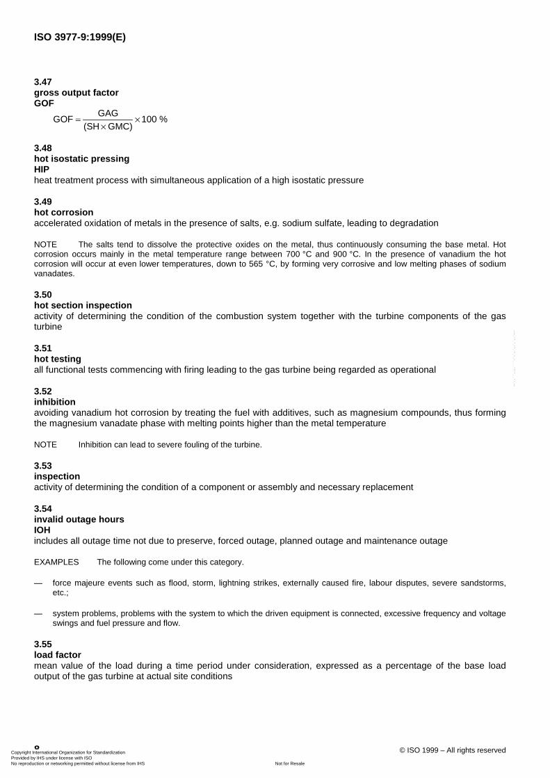
3.47gross output factorGOF
GOFGAG
(SH GMC)100 %�
�
�
3.48hot isostatic pressingHIPheat treatment process with simultaneous application of a high isostatic pressure
3.49hot corrosionaccelerated oxidation of metals in the presence of salts, e.g. sodium sulfate, leading to degradation
NOTE The salts tend to dissolve the protective oxides on the metal, thus continuously consuming the base metal. Hotcorrosion occurs mainly in the metal temperature range between 700 °C and 900 °C. In the presence of vanadium the hotcorrosion will occur at even lower temperatures, down to 565 °C, by forming very corrosive and low melting phases of sodiumvanadates.
3.50hot section inspectionactivity of determining the condition of the combustion system together with the turbine components of the gasturbine
3.51hot testingall functional tests commencing with firing leading to the gas turbine being regarded as operational
3.52inhibitionavoiding vanadium hot corrosion by treating the fuel with additives, such as magnesium compounds, thus formingthe magnesium vanadate phase with melting points higher than the metal temperature
NOTE Inhibition can lead to severe fouling of the turbine.
3.53inspectionactivity of determining the condition of a component or assembly and necessary replacement
3.54invalid outage hoursIOHincludes all outage time not due to preserve, forced outage, planned outage and maintenance outage
EXAMPLES The following come under this category.
— force majeure events such as flood, storm, lightning strikes, externally caused fire, labour disputes, severe sandstorms,etc.;
— system problems, problems with the system to which the driven equipment is connected, excessive frequency and voltageswings and fuel pressure and flow.
3.55load factormean value of the load during a time period under consideration, expressed as a percentage of the base loadoutput of the gas turbine at actual site conditions
Copyright International Organization for Standardization Provided by IHS under license with ISO
Not for ResaleNo reproduction or networking permitted without license from IHS
--`,,```,,,,````-`-`,,`,,`,`,,`---

ISO 3977-9:1999(E)
© ISO 1999 – All rights reserved 9
3.56load rejectionsudden loss or significant reduction of system load causing the turbine unit to momentarily increase speed, thuscoming under the influence of the speed governer or overspeed trip system to avoid undesirable overspeed
3.57major inspectionactivity of determining the condition of the entire gas turbine for a major overhaul
3.58maintenance deratingderating of the gas turbine as the result of the removal of a component for scheduled repairs that can be deferredbeyond the end of the next planned shut down, but requires a reduction of capacity before the next planned shutdown
3.59maintenance derated hoursMDHsum of all hours experienced during maintenance deratings and scheduled derating extensions of any maintenancederatings
3.60maintenance outageMOremoval of a unit from service to perform work on specific components that can be deferred beyond the end of thenext weekend, but requires the unit be removed from service before the next planned outage
3.61maintenance outage extensionSE or MOextension of a maintenance outage
3.62maintenance outage hoursMOHsum of all hours experienced during maintenance outages and maintenance outage extensions
3.63major overhaulthorough overhaul that repairs or replaces those parts deemed necessary to allow the gas turbine to have areasonable expectation of being able to operate for a specified period of time
3.64maintenancesum of all measures intended to determine the actual gas turbine condition, together with the measures required topreserve/restore the specified condition
3.65maintenance costfinancial expenditure in terms of labour and materials for undertaking maintenance
3.66maintenance cycletime period after which a maintenance schedule is repeated
Copyright International Organization for Standardization Provided by IHS under license with ISO
Not for ResaleNo reproduction or networking permitted without license from IHS
--`,,```,,,,````-`-`,,`,,`,`,,`---

ISO 3977-9:1999(E)
10 © ISO 1999 – All rights reserved
3.67mean time between failuresMTBFaverage time between failures which initiate a forced outage, i.e. the ratio of attempted operating hours to thenumber of forced outages:
MTBFPH (RSH FOH POH)
FOSHFO
�� � �
�
where
PH is the period hours
POH is the planned outage hours
RSH is the reserve shutdown/service hours
SH is the service hours
FOH is the forced outage hours
FO is the number of forced outages
NOTE This index is sometimes referred to as the mean time between unplanned outages (MTBO).
3.68mission reliabiltyMR
MR = e��t
where
e is the base of the natural logarithm;
� is the failure rate in events per hour;
t is the mission time in hours.
3.69net actual generationNAGactual amount of energy (in megawatt hours) supplied by the unit during the period being considered, minus anyenergy supplied by the unit for that unit's own station services or utilities
3.70net availability capacityNACgross available capacity minus the unit capacity utilized for that unit's station services or auxiliaries
3.71net capacity factorNCF
NCFNAG
(PH NMC)100 %�
�
�
3.72net dependable capacityNDCgross dependable capacity minus the unit capacity utilized for that unit's station services or auxiliaries
Copyright International Organization for Standardization Provided by IHS under license with ISO
Not for ResaleNo reproduction or networking permitted without license from IHS
--`,,```,,,,````-`-`,,`,,`,`,,`---
ISO 3977-9:1999(E)
© ISO 1999 – All rights reserved 11
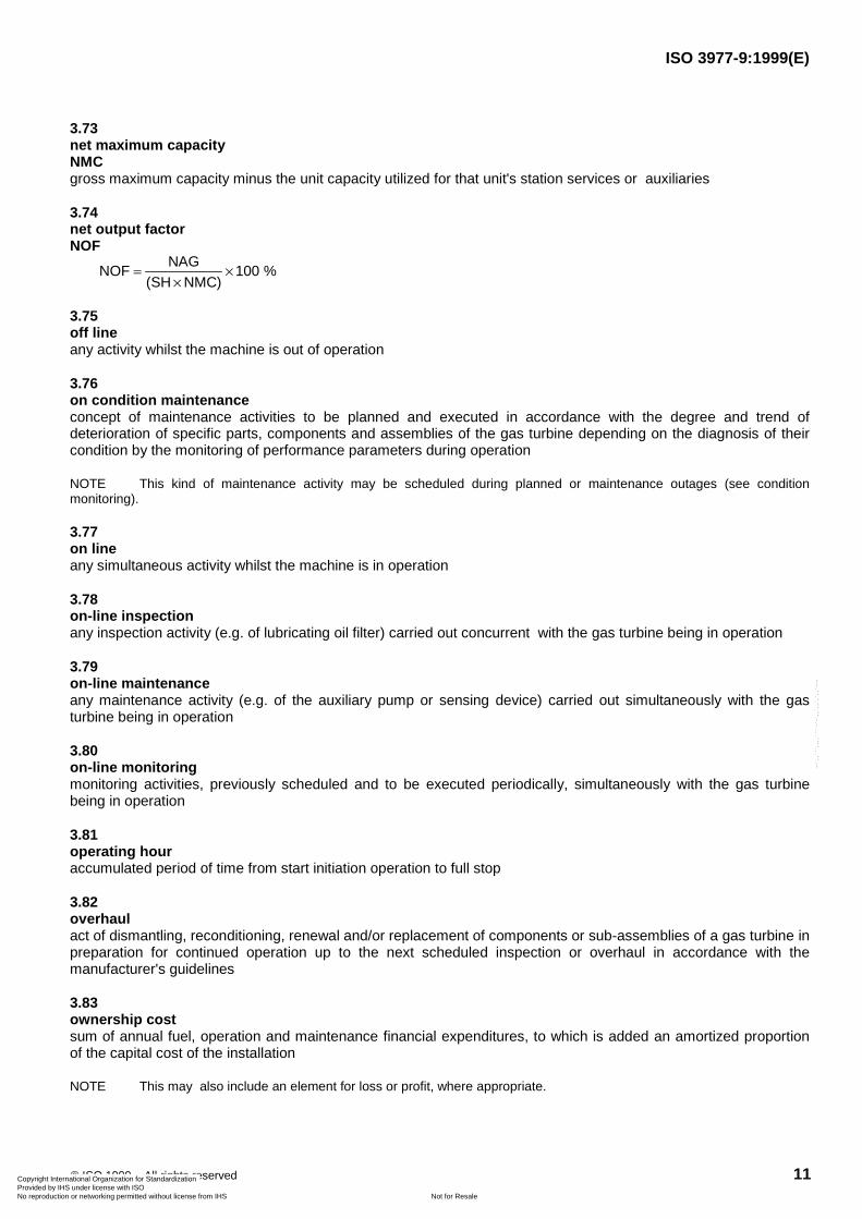
3.73net maximum capacityNMCgross maximum capacity minus the unit capacity utilized for that unit's station services or auxiliaries
3.74net output factorNOF
NOFNAG
(SH NMC)100 %�
�
�
3.75off lineany activity whilst the machine is out of operation
3.76on condition maintenanceconcept of maintenance activities to be planned and executed in accordance with the degree and trend ofdeterioration of specific parts, components and assemblies of the gas turbine depending on the diagnosis of theircondition by the monitoring of performance parameters during operation
NOTE This kind of maintenance activity may be scheduled during planned or maintenance outages (see conditionmonitoring).
3.77on lineany simultaneous activity whilst the machine is in operation
3.78on-line inspectionany inspection activity (e.g. of lubricating oil filter) carried out concurrent with the gas turbine being in operation
3.79on-line maintenanceany maintenance activity (e.g. of the auxiliary pump or sensing device) carried out simultaneously with the gasturbine being in operation
3.80on-line monitoringmonitoring activities, previously scheduled and to be executed periodically, simultaneously with the gas turbinebeing in operation
3.81operating houraccumulated period of time from start initiation operation to full stop
3.82overhaulact of dismantling, reconditioning, renewal and/or replacement of components or sub-assemblies of a gas turbine inpreparation for continued operation up to the next scheduled inspection or overhaul in accordance with themanufacturer's guidelines
3.83ownership costsum of annual fuel, operation and maintenance financial expenditures, to which is added an amortized proportionof the capital cost of the installation
NOTE This may also include an element for loss or profit, where appropriate.
Copyright International Organization for Standardization Provided by IHS under license with ISO
Not for ResaleNo reproduction or networking permitted without license from IHS
--`,,```,,,,````-`-`,,`,,`,`,,`---

ISO 3977-9:1999(E)
12 © ISO 1999 – All rights reserved
3.84pattern factorPFmaximum deviation of the hot gas temperature from the average temperature, divided by the temperature increasein the combustion chamber:
PF =TIT TIT
TIT TVIImax average
average
�
�
where
TITmax is the maximal value of the turbine inlet temperature
TITaverage is the average value of the turbine inlet temperature
TVII is the average value of the compressor outlet temperature
3.85peak ratingnormally expected or guaranteed output of the gas turbine when operating at the specified conditions and at thepeak rated turbine temperature level and in a new and clean condition
NOTE The standard ISO peak rating is for up to 2 000 h of operation per year at peak rated temperature level and 500starts.
3.86performancepower output and efficiency (heat rate) of a gas turbine as stated in the manufacturer's specification
3.87period hoursPHhours in the period under consideration
3.88physical vapour depositionPVDmethod of producing a coating, based on a physical reaction between a gaseous phase of the coating material andthe heated surface of the substrate
NOTE See coating (3.13).
3.89plasma spray coatingAPS or VPSoverlay of a base metal with a special compound of materials basically on the basis of Co-Cr-Al-Y or Ni-Cr-Al-Y toprotect the base metal from hot corrosion
NOTE The coating material is normally added to a hot plasma jet in the form of a powder and sprayed onto the surface ofthe component in the molten phase. The process may take place under atmosphere (APS = atmospheric plasma spray) orunder vacuum (VPS = vacuum plasma spray) [see coating (3.13)].
3.90rapid startfast loadingstarting sequence in which the load is applied to a gas turbine according to an accelerated programme
NOTE This is also referred to as an emergency start.
Copyright International Organization for Standardization Provided by IHS under license with ISO
Not for ResaleNo reproduction or networking permitted without license from IHS
--`,,```,,,,````-`-`,,`,,`,`,,`---

ISO 3977-9:1999(E)
© ISO 1999 – All rights reserved 13
3.91rebuildscomplete or substantially complete overhaul of products without any redesigning
3.92reconditioningrefurbishment and/or repair of parts to obtain the approximate original design condition
3.93redesignconversion or replacement of any components and/or systems to achieve enhanced operational characteristics
3.94reliability factorRFprobability that a unit, major equipment, or component will not be in a forced outage condition at a point in time; i.e.the complement of the ratio of forced outage time (FOH) to total time (PH):
RF 1FOHPH
� �
3.95repairany activity of correction by appropriate measures, including replacement if necessary, of any part of the gasturbine, which is damaged, destroyed or malfunctions or otherwise breaks down
3.96retrofitexchange of major assemblies of a gas turbine by components of a changed design
NOTE See also uprating (3.111) and upgrading (3.110).
3.97scheduled maintenanceplanned maintenance action with preplanned shut down of the gas turbine at a specified time
3.98service hoursSHaccumulated period of time from main flame ignition through to flame extinction
3.99service factorSFratio of service hours to period hours in a period under consideration
SFSHPH
100 %� �
3.100shut downevent in which the unit is brought from operation to a stationary condition under control of a programmed unloadingand stopping sequence
3.101special toolsall/any special tools, equipment and systems required for the operation, maintenance and repair of the gas turbine,which normally are supplied by the manufacturer and are not available in any reasonably equipped tool shop
Copyright International Organization for Standardization Provided by IHS under license with ISO
Not for ResaleNo reproduction or networking permitted without license from IHS
--`,,```,,,,````-`-`,,`,,`,`,,`---

ISO 3977-9:1999(E)
14 © ISO 1999 – All rights reserved
3.102startact of getting the gas turbine and its driven equipment from the ready-to-start condition to the ready-to-loadcondition
NOTE This includes synchronization with the network, breaker closure and stable running thereafter in the case of gasturbines driving alternators, and stable running of the driven equipment for mechanical drive gas turbines.
3.103starting attemptSAaction intended to bring a unit from the shutdown to the in-service state within a specified time
NOTE Repeated initiations of the starting sequence within the allowable specified starting time period without carrying outany corrective repairs are counted as a single attempt. For calculation SA = number of starting attempts.
3.104starting reliabilitySR
SRSS
SS FSSSSA
�
�
�
where
SS is the number of successful starts
FS is the number of failures to start
SA is the number of starting attempts
3.105starting successSSoccurrence of bringing a unit through a starting attempt to the in-service state within a specified period, asevidenced by the maintained closure of the generator to the system or stable operation of the driven equipment
NOTE For calculation SS = number of successful starts.
3.106tripsudden shut down of the unit from load by stopping the fuel supply and opening the load or generator breaker
3.107trip to idlesudden reduction of the unit from load to idle on receipt of an appropriate grade of trip signal
3.108turbine inlet temperatureTITgeneral term indicating the flow-weighted mean total temperature before the turbine
NOTE 1 Depending on the section, there exist different definitions:
— combustor outlet temperature;
— nozzle inlet temperature;
— firing temperature;
— ISO inlet temperature.
Copyright International Organization for Standardization Provided by IHS under license with ISO
Not for ResaleNo reproduction or networking permitted without license from IHS
--`,,```,,,,````-`-`,,`,,`,`,,`---

ISO 3977-9:1999(E)
© ISO 1999 – All rights reserved 15
Combustor outlet temperature is the flow-weighted mean total temperature of the combustion gas at the combustor outletsection after being diluted by the secondary air. Nozzle inlet temperature is the flow-weighted mean total temperature of the hotgas entering the first stage stationary blades after cooling air from the inlet casing has been added downstream of thecombustor outlet. Firing temperature is the flow-weighted mean total temperature of the hot gas before the first stage of rotatingblades after cooling and sealing air from the first stage nozzles and turbine disc has been added to the hot gas after it hasentered the first stage stationary blades. ISO inlet temperature is a flow-weighted mean temperature before the first stagestationary blades calculated from an overall heat balance of the combustion chamber with the total compressor air mass flowand the total fuel mass flow.
NOTE 2 Generally the temperature of the hot gas is never even but there are deviations from the average value to higherand lower temperatures. The maximum deviation is defined by the pattern factor.
3.109turbine outlet temperatureTOTtotal temperature of the hot gas leaving the turbine
3.110upgradingexchanging of components on an existing installation to those of improved design, which may also achieve animprovement in any or all functions except performance
3.111upratingact of increasing the power output and/or efficiency of an existing gas turbine by the exchange of parts designed forthe condition imposed by the increased performance
NOTE Uprating can sometimes be achieved by increasing the turbine inlet temperature, without physical modification aftera successful field trial at a lower, i.e. introductory, rating. See also retrofit (3.96).
4 Maintainability
NOTE The purpose of this clause is to provide a basis for the exchange of maintenance information between the user andmanufacturer.
4.1 Manufacturer's responsibility
4.1.1 General
The manufacturer shall state how the component lives, coating lives and intervals between the different types ofinspection are to be determined and how they are influenced by the operating regime and type of fuel.
4.1.2 Inspection schedules
4.1.2.1 The manufacturer shall provide a schedule of inspections necessary to maintain the unit in a safe andreliable condition. The manufacturer shall state how the component lives, coating lives and intervals between thedifferent types of inspection are to be determined and how they are influenced by the operating regime, type of fueland water or steam injection. As examples, two methods are suggested:
a) method based on assigning equivalent operating hours to every event in the operating history of the unit; and
b) method based on a series of operating regimes to which are related inspection schedules, together withmultipliers to account for different fuels and different loads (base, peak, reserve peak, etc.).
4.1.2.2 Equivalent operating hours, Teq, may be defined as:
T a n a n t f w b t b tii
n
eq 1 1 2 21
1 1� � � � � � �
�
� 2 2b g
Copyright International Organization for Standardization Provided by IHS under license with ISO
Not for ResaleNo reproduction or networking permitted without license from IHS
--`,,```,,,,````-`-`,,`,,`,`,,`---

ISO 3977-9:1999(E)
16 © ISO 1999 – All rights reserved
where
n1 is the number of fired starts;
a1 is the weighting factor for each start;
a2 is the weighting factor for each fast loading;
n2 is the number of fast loading procedures;
ti is the equivalent operating hours for a rapid temperature change, e.g. due to step load changes or trips;
n is the number of rapid temperature changes;
t1 is the operating hours at up to base-load rating;
b1 is the weighting factor for base-load duty;
t2 is the operating hours between base- and peak-load ratings;
b2 is the weighting factor for peak-load duty;
f is the weighting factor for contaminated, out of specification or non-specifiable fuels;
w is the weighting factor for injected water or steam.
The manufacturer states lifetimes and inspection intervals in equivalent operating hours.
4.1.2.3 With different operating regimes the gas turbine manufacturer and/or the user define an annualoperating regime or a series of operating regimes as appropriate. The gas turbine manufacturer then provides arecommended inspection schedule with multipliers for different fuels and load limits. The proposed operatingregimes which represent those found in common practice are:
� A: full-load continuous;
� B: utility-base load;
� C: utility-intermediate;
� D: alternating base and peak load;
� E: daily cycling;
� F: utility-peaking;
� G: emergency standby;
� H: user specific.
Regimes A to G are defined in terms of:
� fired hours;
� service factor;
� fired hours/start;
� fast starts;
� unit trips from full load.
Copyright International Organization for Standardization Provided by IHS under license with ISO
Not for ResaleNo reproduction or networking permitted without license from IHS
--`,,```,,,,````-`-`,,`,,`,`,,`---
ISO 3977-9:1999(E)
© ISO 1999 – All rights reserved 17
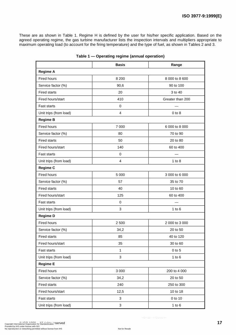
These are as shown in Table 1. Regime H is defined by the user for his/her specific application. Based on theagreed operating regime, the gas turbine manufacturer lists the inspection intervals and multipliers appropriate tomaximum operating load (to account for the firing temperature) and the type of fuel, as shown in Tables 2 and 3.
Table 1 — Operating regime (annual operation)
Basis Range
Regime A
Fired hours 8 200 8 000 to 8 600
Service factor (%) 90,6 90 to 100
Fired starts 20 3 to 40
Fired hours/start 410 Greater than 200
Fast starts 0 —
Unit trips (from load) 4 0 to 8
Regime B
Fired hours 7 000 6 000 to 8 000
Service factor (%) 80 70 to 90
Fired starts 50 20 to 80
Fired hours/start 140 60 to 400
Fast starts 0 —
Unit trips (from load) 4 1 to 8
Regime C
Fired hours 5 000 3 000 to 6 000
Service factor (%) 57 35 to 70
Fired starts 40 10 to 60
Fired hours/start 125 60 to 400
Fast starts 0 —
Unit trips (from load) 3 1 to 6
Regime D
Fired hours 2 500 2 000 to 3 000
Service factor (%) 34,2 20 to 50
Fired starts 85 40 to 120
Fired hours/start 35 30 to 60
Fast starts 1 0 to 5
Unit trips (from load) 3 1 to 6
Regime E
Fired hours 3 000 200 to 4 000
Service factor (%) 34,2 20 to 50
Fired starts 240 250 to 300
Fired hours/start 12,5 10 to 18
Fast starts 3 0 to 10
Unit trips (from load) 3 1 to 6
Copyright International Organization for Standardization Provided by IHS under license with ISO
Not for ResaleNo reproduction or networking permitted without license from IHS
--`,,```,,,,````-`-`,,`,,`,`,,`---

ISO 3977-9:1999(E)
18 © ISO 1999 – All rights reserved
Table 1 (continued)
Basis Range
Regime F
Fired hours 400 200 to 800
Service factor (%) 4,5 2,2 to 10
Fired starts 100 60 to 150
Fired hours/start 4 3 to 8
Fast starts 5 0 to 20
Unit trips (from load) 2 1 to 6
Regime G
Fired hours 48 20 to 80
Service factor (%) 0,5 0,2 to 0,9
Fired starts 30 10 to 120
Fired hours/start 1,6 0,5 to 2
Fast starts 10 0 to 20
Unit trips (from load) 0 0 to 2
The manufacturer shall provide a schedule of inspections indicating the data shown in Tables 2 and 3.
Table 2 — Gas turbine manufacturer's recommended inspection intervals
Months between inspections
Operating regime Combustion Hot gas path Major
A Full-load continuous
B Utility-base load
C Utility-intermediate
D Alternating, base and peak
E Daily cycling
F Utility-peaking
G Emergency standby
H User specific
Copyright International Organization for Standardization Provided by IHS under license with ISO
Not for ResaleNo reproduction or networking permitted without license from IHS
--`,,```,,,,````-`-`,,`,,`,`,,`---

ISO 3977-9:1999(E)
© ISO 1999 – All rights reserved 19
Table 3 — Multipliers to inspection intervals shown in Table 2
Combustion Hot gas path Major
1 Fuel effects
1 a Gas
1 b Alternative gas
1 c Distillate oil
1 d Crude oil
1 e Heavy residual fuel
1 f User specific
2 Firing temperature effects
2 a Base load
2 b Peak load
2 c Reserve peak load
3 Water/steam injection effects
3 a Water
3 b Steam
Together with the schedule of inspections, the manufacturer shall indicate the following for each type of inspection:
� task description;
� estimated outage time;
� estimated parts and material requirements;
� estimated personnel man-hour requirements;
� skill levels, tools, testing equipment and facility requirements;
� recommended location for task accomplishment;
� details of all components and assemblies to be removed from site to a repair centre;
� total time away from site of components and assemblies sent to a repair centre;
� mass of heaviest item to be lifted;
� access required;
� times at which meetings between manufacturer and user shall be held to review previous inspections andoperating history, and to plan the next inspection/overhaul;
� times at which lubricating oil and hydraulic fluid assays should be carried out.
4.1.3 On-line inspection and maintenance
The manufacturer shall state what inspection and maintenance work may be carried out with the gas turbine online, together with any load or speed restrictions which are imposed by these activities. The manufacturer shall alsostate what special equipment is required and what safety precautions shall be observed when carrying out on-lineinspection and maintenance.
Copyright International Organization for Standardization Provided by IHS under license with ISO
Not for ResaleNo reproduction or networking permitted without license from IHS
--`,,```,,,,````-`-`,,`,,`,`,,`---

ISO 3977-9:1999(E)
20 © ISO 1999 – All rights reserved
4.1.4 Condition monitoring
If required by the purchaser and if available, the manufacturer may offer a condition monitoring system, giving fulldetails of the information which needs to be monitored, the frequency of monitoring, how the information isprocessed and any methods of forecasting and/or diagnosis of possible faults, deterioration or the need formaintenance; e.g. trend analysis.
4.1.5 Running maintenance
The manufacturer shall state all inspection and maintenance which shall be carried out as part of normal operationoutside the scheduled inspections, including compressor cleaning, turbine cleaning, filter cleaning, filter changing,oil changing, etc. As part of this requirement, the manufacturer shall indicate all methods available for cleaning,without dismantling the compressor and/or turbine.
4.1.6 Fouling
The manufacturer shall state typical figures for recoverable performance loss due to compressor and/or turbinefouling, based on similar plant on similar operating regimes in similar environments. If turbine fouling is significant, itshould be identified separately.
Information should be provided by the manufacturer to show typical recovery in performance from major and minormaintenance actions, compressor washing, both on-line and off-line, and air intake filter replacement.
4.1.7 Degradation
If required by the purchaser, the manufacurer shall prove predictions of long-term non-recoverable performancedue to ageing, based on experience with similar plant. Information on changes to compressor mass flow,compressor efficiency, gas turbine exhaust temperature, power output and heat rate after periods of 4 000, 8 000,16 000, 32 000 and 48 000 operating hours could be provided.
4.2 User's responsibility
It is the user's responsibilty to carry out the following.
a) Establish a strict fuel purchasing, handling and storage policy to ensure that only as-specified fuel is deliveredto the gas turbine.
This may include monitoring of fuel quality as delivered and stored, the installation of an accurate, calibratedatomic mass spectograph, the use of a gas/liquid chromograph, magnetic plugs, the cleaning and examinationof fouled filters, the maintenance of fuel storage breathing apparatus to restrict the entry of liquids and solids,the periodic cleaning of fuel storage facilities, the use of stainless-steel fuel piping after filtration, off- or on-linecentrifuging as appropriate and the logging of fuel quality.
b) The selection of a suitable grade of operating, maintenance, engineering, store keeping, clerical andmanagerial staff.
c) Periodic training of staff by attendance at manufacturers training courses and international gas turbinemaintenance seminars and congresses.
d) The maintenance of air filtration equipment to ensure only clean air enters the compressor.
e) The strict observation of manufacturer´s operating and maintenance instructions, including:
1) the regular logging/recording of agreed readings as recommended by the gas turbine manufacturer,
2) the periodic calibration of control devices,
3) lubrication as recommended by the manufacturer and care of lubricating oil.
Copyright International Organization for Standardization Provided by IHS under license with ISO
Not for ResaleNo reproduction or networking permitted without license from IHS
--`,,```,,,,````-`-`,,`,,`,`,,`---

ISO 3977-9:1999(E)
© ISO 1999 – All rights reserved 21
f) The anticipation of developing faults from log readings, machine response, leaks, vibration noise, etc.
g) The use only of manufacturer-recommended spare parts and consumables (e.g. air filter media).
h) Maintaining a continuous liaison with the manufacturer, keeping him/her informed of machinery performance,carrying out field maintenance recommendations, etc.
i) Keeping inspection and maintenance records and providing the gas turbine manufacturer with ready access tothese and operational records, as necessary.
j) Planning major maintenance with the manufacturer. This would also apply to major refurbishment or uprating.
k) Proper care and storage of maintenance equipment.
l) The avoidance of rapid load changes and trips and other potentially harmful operating events such as over-load, over-torque, under frequency, malsynchronizing, short circuit, etc.
4.3 Spares holding
The manufacturer, by arrangement with the user, shall provide a list of spare parts required and their usage rate,taking into account:
� the optimum required unit availability and security of power supply;
� the proposed unit operating regime;
� lead time for spare part;
� method of delivery of spares to sit;
� proximity and availability of spares pool;
� proximity and availability of qualified refurbishing facilities;
� access to site;
� facilities available on site.
The spare parts shall be classified into the following categories.
a) Consumable spares
These include the spares to cater for the random failure of minor components during normal operationbetween inspections such as gaskets, "O" rings, thermocouples, temperature switches, pressure switches,filter elements, etc.
b) Overhaul spares
These are spares needed at the various types of scheduled inspection, and could include such components ascombustion chamber flame tubes, transition pieces, cross-fire tubes, turbine blades, turbine vanes, etc.
c) Contingency spares
These are spares to cater for unpredictable failures of components, and could include bearings, auxiliarypumps, sets of compressor blades, complete rotors or gas generators.
Copyright International Organization for Standardization Provided by IHS under license with ISO
Not for ResaleNo reproduction or networking permitted without license from IHS
--`,,```,,,,````-`-`,,`,,`,`,,`---

ISO 3977-9:1999(E)
22 © ISO 1999 – All rights reserved
4.4 Operating log sheets
The manufacturer shall provide, by agreement with the user, operating log sheets in which to record the operatinghistory of the gas turbine and driven unit. Alternatively automatic data recording may be provided. The following isa typical list of data which requires to be logged/recorded.
a) Performance:
� pressure drop across intake air filter
� compressor inlet pressure
� compressor inlet temperature
� compressor discharge pressure
� compressor discharge temperature
� compressor mass flow
� turbine entry pressure
� turbine exhaust pressure
� turbine exhaust temperature t1, t2, t3, t4, t5, ... ti etc.
� fuel flow(s)
� turbine speed (s)
� system frequency
� load
� throttle opening
� guide vane position(s)
� water/steam injection flow
� fuel calorific value
b) Mechanical
� vibration levels
� oil pressures
� oil temperatures
� oil tank level (s)
� cooling air flow (s)
� cooling air pressures
� cooling air temperatures
� cooling air control valve position (s)
Copyright International Organization for Standardization Provided by IHS under license with ISO
Not for ResaleNo reproduction or networking permitted without license from IHS
--`,,```,,,,````-`-`,,`,,`,`,,`---

ISO 3977-9:1999(E)
© ISO 1999 – All rights reserved 23
� cooling water pressure (s)
� cooling water temperature (s)
� acceleration time (s)
� run-down time (s)
c) Emissions
— NOx
— CO
— O2
— CO2
at intervals or continuously as required by regulatory authorities or others
� SO2
� C as soot
� unburnt hydrocarbons (UHC)
d) Availability and reliability
� number of attempted normal starts
� number of attempted fast starts
� number of successful normal starts
� number of successful fast starts
� operating hours up to base load
� operating hours up to peak load
� operating hours as synchronous condenser
� alarms:
� date and time
� reason
� trip-to-idle:
� date and time
� reason
� trips fuel shut-off:
� date and time
� reason
Copyright International Organization for Standardization Provided by IHS under license with ISO
Not for ResaleNo reproduction or networking permitted without license from IHS
--`,,```,,,,````-`-`,,`,,`,`,,`---
ISO 3977-9:1999(E)
24 © ISO 1999 – All rights reserved
� outage events:
� date and time of outage
� date and time of end of outage
� location
� mode
� cause
� consequence
� measures
� shut down
� date, time and reason
� energy generated
5 Reliability and availability
5.1 Reliability acceptance tests
Reliability acceptance tests are short-duration tests that do not accurately measure long-term inherent equipmentreliability or availability, but rather serve to screen for the acceptability (or thoroughness) of manufacturing andinstallation. The remedy for failure of a reliability acceptance test shall be to apply generic correction to theobserved deficiencies and then re-attempt the test.
ISO 2314:1989, subclause 7.2.3.2, specifies a starting reliability acceptance test which reads as follows: "Startingreliability shall have been attained when ten consecutive successful starts are performed in accordance withoperating instructions supplied with the unit."
Another common form of a reliability acceptance test is the 15-day or 30-day demonstration test, for which successis defined as not exceeding X forced outage events or Y equivalent plant outage hours over the duration of the test.If the user requests this type of reliability acceptance test, the supplier shall provide values for both X and Yappropriate to the plant configuration and normal operating expectations. As a reasonable guideline, the X valueshould yield at least 70 % probability (Poisson) for individual test success based on the life-cycle expected forcedoutage event rate. The Y value should correspond to the expected life-cycle plant equivalent availability. Theremedy for failure is to re-try the test.
5.2 Reliability and availability, calculating and reporting
Availabilty and reliability information should be calculated and reported using the terms and definitions shown inclause 3. Additional availability and reliability information may be found in definitions from standards institutes suchas ISO, IEC, DIN, VDE, NERC, IEEE, CEI, ANSI, etc.
Copyright International Organization for Standardization Provided by IHS under license with ISO
Not for ResaleNo reproduction or networking permitted without license from IHS
--`,,```,,,,````-`-`,,`,,`,`,,`---
ISO 3977-9:1999(E)
© ISO 1999 – All rights reserved 25
6 Safety
6.1 General
This clause is confined to those aspects of safety that are controllable by adequate design and implementation ofthe design. It does not cover such safety considerations as personnel training, procedures, and usage of personnelprotective equipment.
6.2 Safety elements
Safety is of paramount importance in any power plant including a gas turbine power plant. Protection from bothhuman and equipment safety hazards is required. Design and its implementation shall be in accordance withapplicable mandatory regulations, standards, etc. Careful attention shall be given to the following safety elements.
a) Minimization of fire hazards and provisions for appropriate fire control.
b) Control systems designed to prevent unsafe conditions (speeds, temperature, vibration, etc.).
c) Alarms to warn of unsafe operating conditions.
d) Suitable safety trips to protect operating personnel and/or equipment.
e) If operators will be near the gas turbine while it is operating, guards, insulation, handrails, etc., should beprovided to protect personnel from accidental contact with dangerous elements. Where appropriate, warningsignals shall also be supplied.
f) Proper handling equipment and tools shall be available to maintenance personnel; particular attention isrequired for the safe handling of heavy equipment, including rigging or blocking tools, slings, hoists andcranes.
g) Power plant design shall minimize the possibility of a fire fed by lubricating oil, hydraulic oil and fuel oil leaks(localizing any potential leaks shall be given careful attention).
h) Adequate ventilation and means of escape shall be provided for any personnel who will be near the powerplant when it is operating; recognition shall be given to the fact that fire protection systems operating in aconfined area can be dangerous to personnel.
i) Manufacturers' recommendations relative to occupancy of the gas turbine enclosure during operation shall befollowed.
j) If operators are to be exposed to abnormal sound levels, suitable protective ear devices shall be worn.
k) Operating and maintenance personnel shall be provided with instructions to promote safe operation andmaintenance of the power plant.
l) The inter-relationship of the gas turbine protective equipment and its possible effect on other power plant orsystem equipment.
m) Power plant design shall minimize the possibility of fuel gas leakage and gas explosion by provision of suitablearrangements for venting, gas detection, cell/building ventilation, equipment spark suppression, pipeworkearthing/bonding, etc.
Copyright International Organization for Standardization Provided by IHS under license with ISO
Not for ResaleNo reproduction or networking permitted without license from IHS
--`,,```,,,,````-`-`,,`,,`,`,,`---
ISO 3977-9:1999(E)
ICS 27.040Price based on 25 pages
© ISO 1999 – All rights reserved
Copyright International Organization for Standardization Provided by IHS under license with ISO
Not for ResaleNo reproduction or networking permitted without license from IHS
--`,,```,,,,````-`-`,,`,,`,`,,`---