Embed Size (px)
Citation preview
© ISO 2013
Road vehicles — Design and performance specifications for the WorldSID 50th percentile male side impact dummy —Part 4: User’s manualVéhicules routiers — Conception et spécifications de performance pour le mannequin mondial (WorldSID), 50e percentile homme, de choc latéral —Partie 4: Manuel de l’utilisateur
INTERNATIONAL STANDARD
ISO15830-4
Second edition2013-05-15
Reference numberISO 15830-4:2013(E)
iTeh STANDARD PREVIEW(standards.iteh.ai)
ISO 15830-4:2013https://standards.iteh.ai/catalog/standards/sist/91aa1080-0833-43f8-a1f4-
78f88737bb76/iso-15830-4-2013

ISO 15830-4:2013(E)
ii © ISO 2013 – All rights reserved
COPYRIGHT PROTECTED DOCUMENT
© ISO 2013All rights reserved. Unless otherwise specified, no part of this publication may be reproduced or utilized otherwise in any form or by any means, electronic or mechanical, including photocopying, or posting on the internet or an intranet, without prior written permission. Permission can be requested from either ISO at the address below or ISO’s member body in the country of the requester.
ISO copyright officeCase postale 56 • CH-1211 Geneva 20Tel. + 41 22 749 01 11Fax + 41 22 749 09 47E-mail [email protected] www.iso.org
Published in Switzerland
iTeh STANDARD PREVIEW(standards.iteh.ai)
ISO 15830-4:2013https://standards.iteh.ai/catalog/standards/sist/91aa1080-0833-43f8-a1f4-
78f88737bb76/iso-15830-4-2013
ISO 15830-4:2013(E)
© ISO 2013 – All rights reserved iii
Contents Page
Foreword ........................................................................................................................................................................................................................................ivIntroduction ..................................................................................................................................................................................................................................v1 Scope ................................................................................................................................................................................................................................. 12 Normative references ...................................................................................................................................................................................... 13 Terms and definitions ..................................................................................................................................................................................... 14 Requirements .......................................................................................................................................................................................................... 1
4.1 Disassembly and assembly ........................................................................................................................................................... 14.2 Full arm changeover ........................................................................................................................................................................... 1
Annex A (normative) Procedures for disassembling and assembling the WorldSID ......................................... 2Annex B (informative) Overview of an example permissible internal data acquisition system .........81Annex C (normative) Fastener torque values ...........................................................................................................................................89Annex D (informative) Fastener abbreviations and ISO references for user convenience .......................91Annex E (informative) Recommended WorldSID general practices .................................................................................92Annex F (informative) Recommended WorldSID seating procedure ...............................................................................95Annex G (informative) Suggested WorldSID wiring procedures ...........................................................................................96Annex H (informative) WorldSID temperature information ................................................................................................ 112Annex I (normative) Recommended WorldSID grounding scheme .............................................................................. 114
iTeh STANDARD PREVIEW(standards.iteh.ai)
ISO 15830-4:2013https://standards.iteh.ai/catalog/standards/sist/91aa1080-0833-43f8-a1f4-
78f88737bb76/iso-15830-4-2013
ISO 15830-4:2013(E)
Foreword
ISO (the International Organization for Standardization) is a worldwide federation of national standards bodies (ISO member bodies). The work of preparing International Standards is normally carried out through ISO technical committees. Each member body interested in a subject for which a technical committee has been established has the right to be represented on that committee. International organizations, governmental and non-governmental, in liaison with ISO, also take part in the work. ISO collaborates closely with the International Electrotechnical Commission (IEC) on all matters of electrotechnical standardization.
The procedures used to develop this document and those intended for its further maintenance are described in the ISO/IEC Directives, Part 1. In particular the different approval criteria needed for the different types of ISO documents should be noted. This document was drafted in accordance with the editorial rules of the ISO/IEC Directives, Part 2. www.iso.org/directives
Attention is drawn to the possibility that some of the elements of this document may be the subject of patent rights. ISO shall not be held responsible for identifying any or all such patent rights. Details of any patent rights identified during the development of the document will be in the Introduction and/or on the ISO list of patent declarations received. www.iso.org/patents
Any trade name used in this document is information given for the convenience of users and does not constitute an endorsement.
The committee responsible for this document is ISO/TC 22, Road vehicles, Subcommittee SC 12, Passive safety crash protection systems.
This second edition cancels and replaces the first edition (ISO 15830-4:2005) which has been technically revised. Technical amendments have been incorporated throughout all four parts, resulting from extensive experience with the standard and design changes.
ISO 15830 consists of the following parts, under the general title Road vehicles — Design and performance specifications for the WorldSID 50th percentile male side impact dummy:
— Part 1: Terminology and rationale
— Part 2: Mechanical subsystems
— Part 3: Electronic subsystems
— Part 4: User’s manual
iv © ISO 2013 – All rights reserved
iTeh STANDARD PREVIEW(standards.iteh.ai)
ISO 15830-4:2013https://standards.iteh.ai/catalog/standards/sist/91aa1080-0833-43f8-a1f4-
78f88737bb76/iso-15830-4-2013
ISO 15830-4:2013(E)
Introduction
This second edition of ISO 15830 has been prepared on the basis of the existing design, specifications, and performance of the WorldSID 50th percentile adult male side impact dummy. The purpose of the ISO 15830 series is to document the design and specifications of this side impact dummy in a form suitable and intended for worldwide regulatory use.
In 1997, ISO/TC22/SC12 initiated the WorldSID 50th percentile adult male dummy development, with the aims of defining a global-consensus side impact dummy, having a wider range of human-like anthropometry, biofidelity, and injury monitoring capabilities, suitable for regulatory use. Participating in the development were research institutes, dummy and instrumentation manufacturers, governments, and vehicle manufacturers from around the world.
With regard to potential regulatory, consumer information, or research and development use of ISO 15830, users will need to identify which of the permissive (i.e. optional) sensors and other elements defined in ISO 15830-3 are to be used in a given application.
WorldSID drawings in electronic format are being made available. Details are given in ISO 15830-2:2013, Annex B.
In order to apply ISO 15830 properly, it is important that all four parts be used together.
© ISO 2013 – All rights reserved v
iTeh STANDARD PREVIEW(standards.iteh.ai)
ISO 15830-4:2013https://standards.iteh.ai/catalog/standards/sist/91aa1080-0833-43f8-a1f4-
78f88737bb76/iso-15830-4-2013

iTeh STANDARD PREVIEW(standards.iteh.ai)
ISO 15830-4:2013https://standards.iteh.ai/catalog/standards/sist/91aa1080-0833-43f8-a1f4-
78f88737bb76/iso-15830-4-2013
Road vehicles — Design and performance specifications for the WorldSID 50th percentile male side impact dummy —
Part 4: User’s manual
1 Scope
This part of ISO 15830 specifies requirements for assembling and disassembling of the WorldSID 50th percentile side impact dummy, a standardized anthropomorphic dummy for side impact testing of road vehicles.
It is applicable to impact tests involving
— passenger vehicles of categories M1 and goods vehicles of categories N1,
— impacts to the side of the vehicle structure,
— impact tests involving the use of an anthropometric dummy as a human surrogate for the purpose of evaluating compliance with vehicle safety standards.
2 Normative references
The following documents, in whole or in part, are normatively referenced in this document and are indispensable for its application. For dated references, only the edition cited applies. For undated references, the latest edition of the referenced document (including any amendments) applies.
ISO 15830-1, Design and performance specifications for the WorldSID 50th percentile adult male side impact dummy — Part 1: Terminology and rationale
ISO 15830-3:2013, Design and performance specifications for the WorldSID 50th percentile adult male side impact dummy — Part 3: Electronic subsystems
3 Terms and definitions
For the purposes of this document, the terms and definitions given in ISO 15830-1 apply.
4 Requirements
4.1 Disassembly and assembly
The WorldSID shall be disassembled and assembled according to the procedures in Annex A.
Unless noted otherwise, all fasteners shall be installed using the torques in Annex C.
4.2 Full arm changeover
If a full arm is to be relocated from the left side of the dummy to the right side or from the right side of the dummy to the left side, then this shall be done using the procedures given in A.4.5.
INTERNATIONAL STANDARD ISO 15830-4:2013(E)
© ISO 2013 – All rights reserved 1
iTeh STANDARD PREVIEW(standards.iteh.ai)
ISO 15830-4:2013https://standards.iteh.ai/catalog/standards/sist/91aa1080-0833-43f8-a1f4-
78f88737bb76/iso-15830-4-2013
ISO 15830-4:2013(E)
Annex A (normative)
Procedures for disassembling and assembling the WorldSID
A.1 Head
A.1.1 Parts list for head
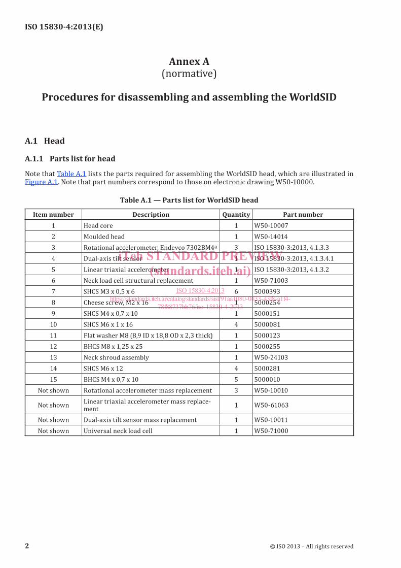
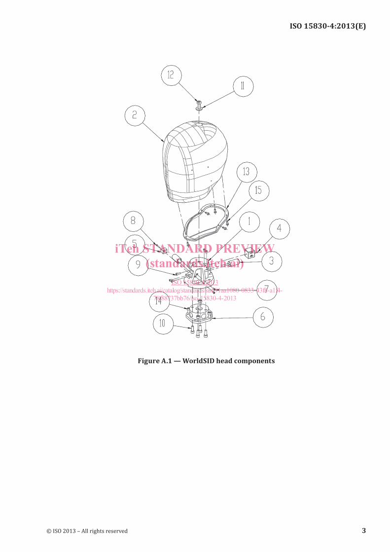
Note that Table A.1 lists the parts required for assembling the WorldSID head, which are illustrated in Figure A.1. Note that part numbers correspond to those on electronic drawing W50-10000.
Table A.1 — Parts list for WorldSID head
Item number Description Quantity Part number1 Head core 1 W50-100072 Moulded head 1 W50-140143 Rotational accelerometer, Endevco 7302BM4a 3 ISO 15830-3:2013, 4.1.3.34 Dual-axis tilt sensor 1 ISO 15830-3:2013, 4.1.3.4.15 Linear triaxial accelerometer 1 ISO 15830-3:2013, 4.1.3.26 Neck load cell structural replacement 1 W50-710037 SHCS M3 x 0,5 x 6 6 50003938 Cheese screw, M2 x 16 1 50002549 SHCS M4 x 0,7 x 10 1 5000151
10 SHCS M6 x 1 x 16 4 500008111 Flat washer M8 (8,9 ID x 18,8 OD x 2,3 thick) 1 500012312 BHCS M8 x 1,25 x 25 1 500025513 Neck shroud assembly 1 W50-2410314 SHCS M6 x 12 4 500028115 BHCS M4 x 0,7 x 10 5 5000010
Not shown Rotational accelerometer mass replacement 3 W50-10010
Not shown Linear triaxial accelerometer mass replace-ment 1 W50-61063
Not shown Dual-axis tilt sensor mass replacement 1 W50-10011Not shown Universal neck load cell 1 W50-71000
2 © ISO 2013 – All rights reserved
iTeh STANDARD PREVIEW(standards.iteh.ai)
ISO 15830-4:2013https://standards.iteh.ai/catalog/standards/sist/91aa1080-0833-43f8-a1f4-
78f88737bb76/iso-15830-4-2013
ISO 15830-4:2013(E)
Figure A.1 — WorldSID head components
© ISO 2013 – All rights reserved 3
iTeh STANDARD PREVIEW(standards.iteh.ai)
ISO 15830-4:2013https://standards.iteh.ai/catalog/standards/sist/91aa1080-0833-43f8-a1f4-
78f88737bb76/iso-15830-4-2013
ISO 15830-4:2013(E)
A.1.2 Disassembling
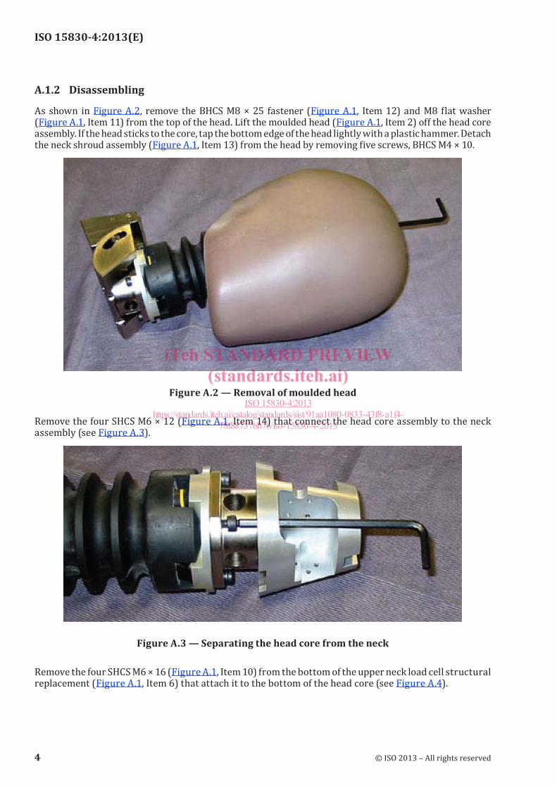
As shown in Figure A.2, remove the BHCS M8 × 25 fastener (Figure A.1, Item 12) and M8 flat washer (Figure A.1, Item 11) from the top of the head. Lift the moulded head (Figure A.1, Item 2) off the head core assembly. If the head sticks to the core, tap the bottom edge of the head lightly with a plastic hammer. Detach the neck shroud assembly (Figure A.1, Item 13) from the head by removing five screws, BHCS M4 × 10.
Figure A.2 — Removal of moulded head
Remove the four SHCS M6 × 12 (Figure A.1, Item 14) that connect the head core assembly to the neck assembly (see Figure A.3).
Figure A.3 — Separating the head core from the neck
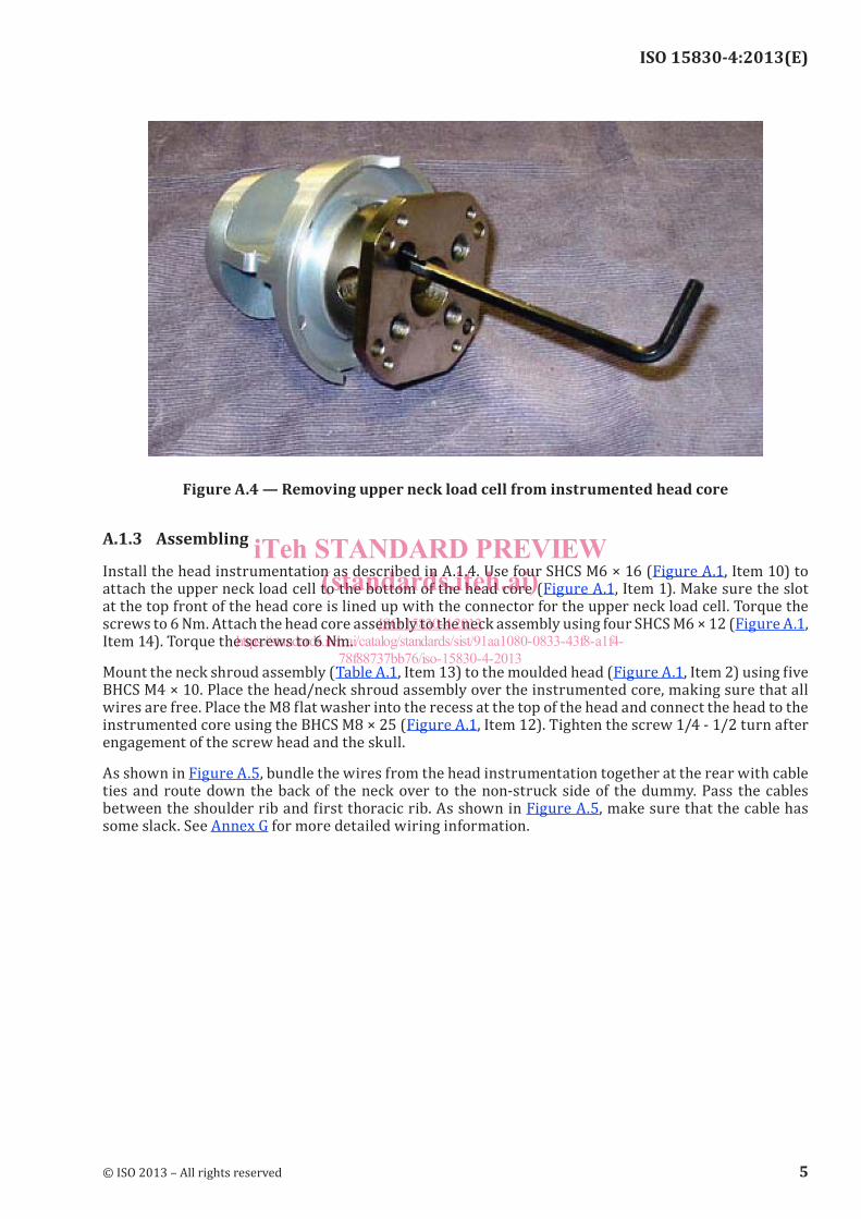
Remove the four SHCS M6 × 16 (Figure A.1, Item 10) from the bottom of the upper neck load cell structural replacement (Figure A.1, Item 6) that attach it to the bottom of the head core (see Figure A.4).
4 © ISO 2013 – All rights reserved
iTeh STANDARD PREVIEW(standards.iteh.ai)
ISO 15830-4:2013https://standards.iteh.ai/catalog/standards/sist/91aa1080-0833-43f8-a1f4-
78f88737bb76/iso-15830-4-2013
ISO 15830-4:2013(E)
Figure A.4 — Removing upper neck load cell from instrumented head core
A.1.3 Assembling
Install the head instrumentation as described in A.1.4. Use four SHCS M6 × 16 (Figure A.1, Item 10) to attach the upper neck load cell to the bottom of the head core (Figure A.1, Item 1). Make sure the slot at the top front of the head core is lined up with the connector for the upper neck load cell. Torque the screws to 6 Nm. Attach the head core assembly to the neck assembly using four SHCS M6 × 12 (Figure A.1, Item 14). Torque the screws to 6 Nm.
Mount the neck shroud assembly (Table A.1, Item 13) to the moulded head (Figure A.1, Item 2) using five BHCS M4 × 10. Place the head/neck shroud assembly over the instrumented core, making sure that all wires are free. Place the M8 flat washer into the recess at the top of the head and connect the head to the instrumented core using the BHCS M8 × 25 (Figure A.1, Item 12). Tighten the screw 1/4 - 1/2 turn after engagement of the screw head and the skull.
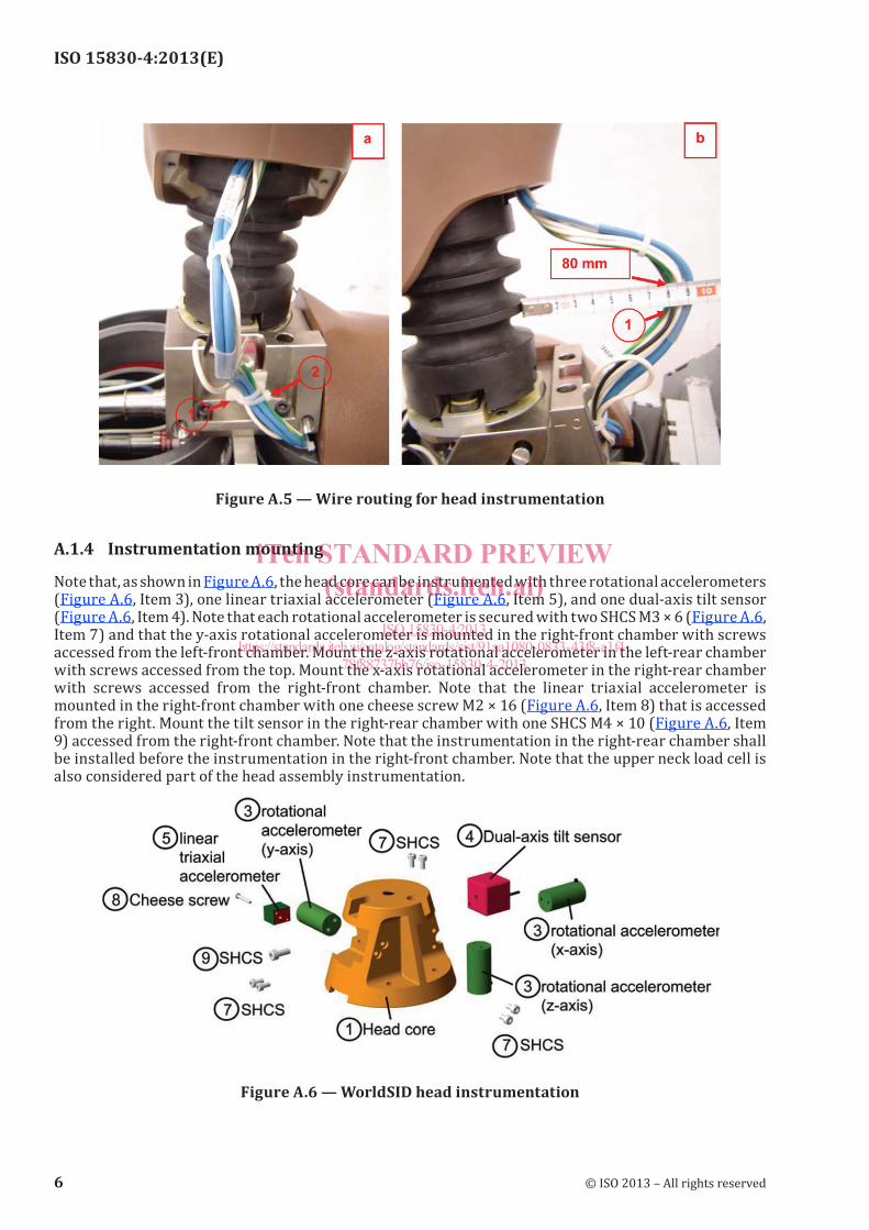
As shown in Figure A.5, bundle the wires from the head instrumentation together at the rear with cable ties and route down the back of the neck over to the non-struck side of the dummy. Pass the cables between the shoulder rib and first thoracic rib. As shown in Figure A.5, make sure that the cable has some slack. See Annex G for more detailed wiring information.
© ISO 2013 – All rights reserved 5
iTeh STANDARD PREVIEW(standards.iteh.ai)
ISO 15830-4:2013https://standards.iteh.ai/catalog/standards/sist/91aa1080-0833-43f8-a1f4-
78f88737bb76/iso-15830-4-2013
ISO 15830-4:2013(E)
Figure A.5 — Wire routing for head instrumentation
A.1.4 Instrumentation mounting
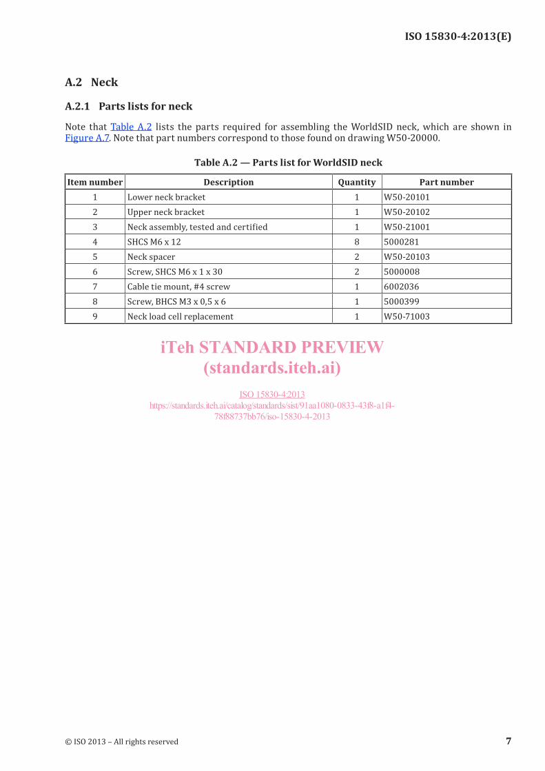
Note that, as shown in Figure A.6, the head core can be instrumented with three rotational accelerometers (Figure A.6, Item 3), one linear triaxial accelerometer (Figure A.6, Item 5), and one dual-axis tilt sensor (Figure A.6, Item 4). Note that each rotational accelerometer is secured with two SHCS M3 × 6 (Figure A.6, Item 7) and that the y-axis rotational accelerometer is mounted in the right-front chamber with screws accessed from the left-front chamber. Mount the z-axis rotational accelerometer in the left-rear chamber with screws accessed from the top. Mount the x-axis rotational accelerometer in the right-rear chamber with screws accessed from the right-front chamber. Note that the linear triaxial accelerometer is mounted in the right-front chamber with one cheese screw M2 × 16 (Figure A.6, Item 8) that is accessed from the right. Mount the tilt sensor in the right-rear chamber with one SHCS M4 × 10 (Figure A.6, Item 9) accessed from the right-front chamber. Note that the instrumentation in the right-rear chamber shall be installed before the instrumentation in the right-front chamber. Note that the upper neck load cell is also considered part of the head assembly instrumentation.
Figure A.6 — WorldSID head instrumentation
6 © ISO 2013 – All rights reserved
iTeh STANDARD PREVIEW(standards.iteh.ai)
ISO 15830-4:2013https://standards.iteh.ai/catalog/standards/sist/91aa1080-0833-43f8-a1f4-
78f88737bb76/iso-15830-4-2013
ISO 15830-4:2013(E)
A.2 Neck
A.2.1 Parts lists for neck
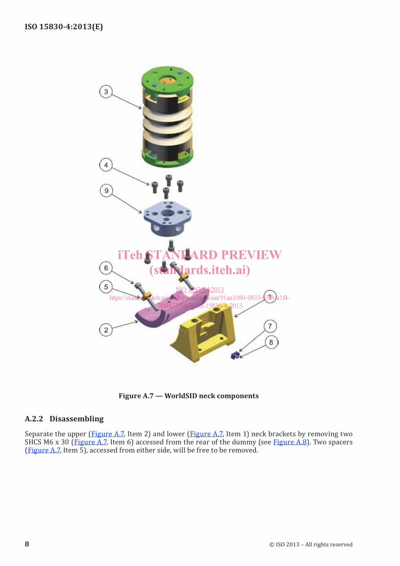
Note that Table A.2 lists the parts required for assembling the WorldSID neck, which are shown in Figure A.7. Note that part numbers correspond to those found on drawing W50-20000.
Table A.2 — Parts list for WorldSID neck
Item number Description Quantity Part number1 Lower neck bracket 1 W50-201012 Upper neck bracket 1 W50-201023 Neck assembly, tested and certified 1 W50-210014 SHCS M6 x 12 8 50002815 Neck spacer 2 W50-201036 Screw, SHCS M6 x 1 x 30 2 50000087 Cable tie mount, #4 screw 1 60020368 Screw, BHCS M3 x 0,5 x 6 1 50003999 Neck load cell replacement 1 W50-71003
© ISO 2013 – All rights reserved 7
iTeh STANDARD PREVIEW(standards.iteh.ai)
ISO 15830-4:2013https://standards.iteh.ai/catalog/standards/sist/91aa1080-0833-43f8-a1f4-
78f88737bb76/iso-15830-4-2013
ISO 15830-4:2013(E)
Figure A.7 — WorldSID neck components
A.2.2 Disassembling
Separate the upper (Figure A.7, Item 2) and lower (Figure A.7, Item 1) neck brackets by removing two SHCS M6 x 30 (Figure A.7, Item 6) accessed from the rear of the dummy (see Figure A.8). Two spacers (Figure A.7, Item 5), accessed from either side, will be free to be removed.
8 © ISO 2013 – All rights reserved
iTeh STANDARD PREVIEW(standards.iteh.ai)
ISO 15830-4:2013https://standards.iteh.ai/catalog/standards/sist/91aa1080-0833-43f8-a1f4-
78f88737bb76/iso-15830-4-2013
ISO 15830-4:2013(E)
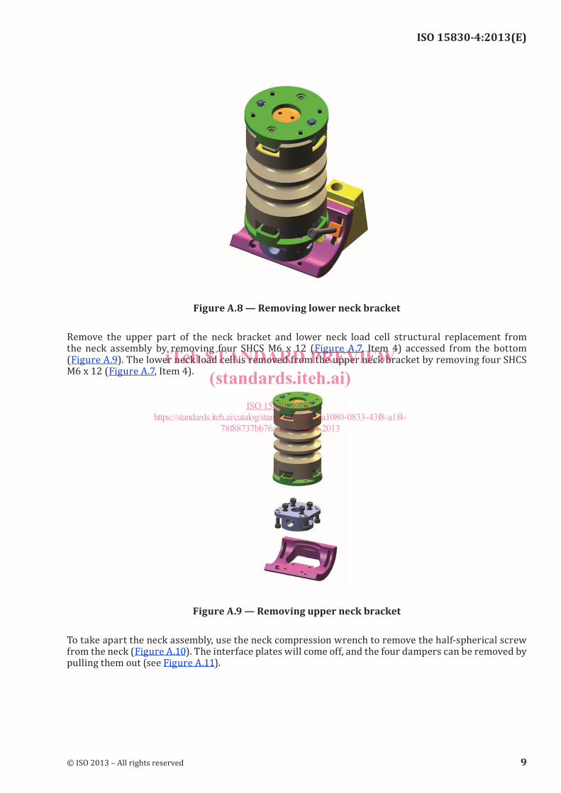
Figure A.8 — Removing lower neck bracket
Remove the upper part of the neck bracket and lower neck load cell structural replacement from the neck assembly by removing four SHCS M6 x 12 (Figure A.7, Item 4) accessed from the bottom (Figure A.9). The lower neck load cell is removed from the upper neck bracket by removing four SHCS M6 x 12 (Figure A.7, Item 4).
Figure A.9 — Removing upper neck bracket
To take apart the neck assembly, use the neck compression wrench to remove the half-spherical screw from the neck (Figure A.10). The interface plates will come off, and the four dampers can be removed by pulling them out (see Figure A.11).
© ISO 2013 – All rights reserved 9
iTeh STANDARD PREVIEW(standards.iteh.ai)
ISO 15830-4:2013https://standards.iteh.ai/catalog/standards/sist/91aa1080-0833-43f8-a1f4-
78f88737bb76/iso-15830-4-2013