Embed Size (px)
Citation preview

Road vehicles — Engine test code — Net powerVéhicules routiers — Code d'essai des moteurs — Puissance nette
© ISO 2020
INTERNATIONAL STANDARD
ISO1585
Fourth edition2020-07
Reference numberISO 1585:2020(E)
iTeh STANDARD PREVIEW(standards.iteh.ai)
ISO 1585:2020https://standards.iteh.ai/catalog/standards/sist/14b70ffa-8765-4249-9418-
874a1e17cfae/iso-1585-2020

ISO 1585:2020(E)
ii © ISO 2020 – All rights reserved
COPYRIGHT PROTECTED DOCUMENT
© ISO 2020All rights reserved. Unless otherwise specified, or required in the context of its implementation, no part of this publication may be reproduced or utilized otherwise in any form or by any means, electronic or mechanical, including photocopying, or posting on the internet or an intranet, without prior written permission. Permission can be requested from either ISO at the address below or ISO’s member body in the country of the requester.
ISO copyright officeCP 401 • Ch. de Blandonnet 8CH-1214 Vernier, GenevaPhone: +41 22 749 01 11Email: [email protected]: www.iso.org
Published in Switzerland
iTeh STANDARD PREVIEW(standards.iteh.ai)
ISO 1585:2020https://standards.iteh.ai/catalog/standards/sist/14b70ffa-8765-4249-9418-
874a1e17cfae/iso-1585-2020
ISO 1585:2020(E)
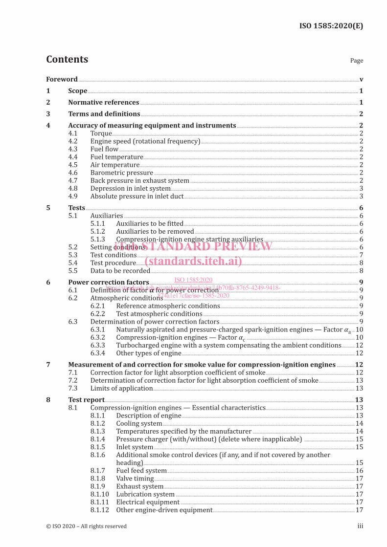
Foreword ..........................................................................................................................................................................................................................................v1 Scope ................................................................................................................................................................................................................................. 12 Normative references ...................................................................................................................................................................................... 13 Termsanddefinitions ..................................................................................................................................................................................... 24 Accuracy of measuring equipment and instruments ..................................................................................................... 2
4.1 Torque ............................................................................................................................................................................................................. 24.2 Engine speed (rotational frequency) ................................................................................................................................... 24.3 Fuel flow ....................................................................................................................................................................................................... 24.4 Fuel temperature................................................................................................................................................................................... 24.5 Air temperature ...................................................................................................................................................................................... 24.6 Barometric pressure .......................................................................................................................................................................... 24.7 Back pressure in exhaust system ............................................................................................................................................ 24.8 Depression in inlet system ............................................................................................................................................................ 34.9 Absolute pressure in inlet duct ................................................................................................................................................. 3
5 Tests ................................................................................................................................................................................................................................... 65.1 Auxiliaries ................................................................................................................................................................................................... 6
5.1.1 Auxiliaries to be fitted ................................................................................................................................................. 65.1.2 Auxiliaries to be removed ........................................................................................................................................ 65.1.3 Compression-ignition engine starting auxiliaries ............................................................................... 6
5.2 Setting conditions ................................................................................................................................................................................. 65.3 Test conditions ........................................................................................................................................................................................ 75.4 Test procedure ......................................................................................................................................................................................... 85.5 Data to be recorded ............................................................................................................................................................................. 8
6 Power correction factors .............................................................................................................................................................................. 96.1 Definition of factor α for power correction .................................................................................................................... 96.2 Atmospheric conditions .................................................................................................................................................................. 9
6.2.1 Reference atmospheric conditions ................................................................................................................... 96.2.2 Test atmospheric conditions ................................................................................................................................. 9
6.3 Determination of power correction factors ................................................................................................................... 96.3.1 Naturally aspirated and pressure-charged spark-ignition engines — Factor αa ..106.3.2 Compression-ignition engines — Factor αc ..........................................................................................106.3.3 Turbocharged engine with a system compensating the ambient conditions ...........126.3.4 Other types of engine ................................................................................................................................................12
7 Measurement of and correction for smoke value for compression-ignition engines ...............127.1 Correction factor for light absorption coefficient of smoke ..........................................................................127.2 Determination of correction factor for light absorption coefficient of smoke ..............................137.3 Limits of application........................................................................................................................................................................ 13
8 Test report ................................................................................................................................................................................................................138.1 Compression-ignition engines — Essential characteristics ..........................................................................13
8.1.1 Description of engine ................................................................................................................................................138.1.2 Cooling system ................................................................................................................................................................148.1.3 Temperatures specified by the manufacturer .....................................................................................148.1.4 Pressure charger (with/without) (delete where inapplicable) ..........................................158.1.5 Inlet system ....................................................................................................................................................................... 158.1.6 Additional smoke control devices (if any, and if not covered by another
heading) ................................................................................................................................................................................158.1.7 Fuel feed system ............................................................................................................................................................168.1.8 Valve timing ....................................................................................................................................................................... 178.1.9 Exhaust system ...............................................................................................................................................................178.1.10 Lubrication system .....................................................................................................................................................178.1.11 Electrical equipment .................................................................................................................................................178.1.12 Other engine-driven equipment ...................................................................................................................... 17
© ISO 2020 – All rights reserved iii
Contents Page
iTeh STANDARD PREVIEW(standards.iteh.ai)
ISO 1585:2020https://standards.iteh.ai/catalog/standards/sist/14b70ffa-8765-4249-9418-
874a1e17cfae/iso-1585-2020

ISO 1585:2020(E)
8.2 Spark-ignition engines — Essential characteristics ............................................................................................178.2.1 Description of engine ................................................................................................................................................178.2.2 Cooling system ................................................................................................................................................................188.2.3 Temperature specified by the manufacturer ........................................................................................198.2.4 Pressure charger (with/without) (delete where inapplicable) ..........................................198.2.5 Inlet system ....................................................................................................................................................................... 198.2.6 Additional anti-pollution devices (if any, and if not covered by another
heading) ..............................................................................................................................................................................208.2.7 Fuel feed system ............................................................................................................................................................208.2.8 Valve timing ....................................................................................................................................................................... 208.2.9 Ignition system ...............................................................................................................................................................208.2.10 Exhaust system ...............................................................................................................................................................218.2.11 Lubrication system .....................................................................................................................................................218.2.12 Electrical equipment .................................................................................................................................................228.2.13 Other auxiliaries fitted to engine .................................................................................................................... 22
8.3 Test conditions for measuring engine net power ..................................................................................................228.4 Statement of results as function of engine speed...................................................................................................24
9 Verificationofengineperformance ...............................................................................................................................................259.1 Designation ............................................................................................................................................................................................. 259.2 Notation ..................................................................................................................................................................................................... 25
9.2.1 Declared net power and corresponding engine speed (range) ............................................259.2.2 Declared net torque and corresponding engine speed (range) ...........................................269.2.3 Declared specific net fuel consumption and corresponding engine speed
(range) ...................................................................................................................................................................................269.3 Tolerances — Declared values ................................................................................................................................................ 26
9.3.1 Power ...................................................................................................................................................................................... 269.3.2 Torque .................................................................................................................................................................................... 279.3.3 Specific fuel consumption ..................................................................................................................................... 279.3.4 Numerical tolerances ................................................................................................................................................27
Bibliography .............................................................................................................................................................................................................................32
iv © ISO 2020 – All rights reserved
iTeh STANDARD PREVIEW(standards.iteh.ai)
ISO 1585:2020https://standards.iteh.ai/catalog/standards/sist/14b70ffa-8765-4249-9418-
874a1e17cfae/iso-1585-2020

ISO 1585:2020(E)
Foreword
ISO (the International Organization for Standardization) is a worldwide federation of national standards bodies (ISO member bodies). The work of preparing International Standards is normally carried out through ISO technical committees. Each member body interested in a subject for which a technical committee has been established has the right to be represented on that committee. International organizations, governmental and non-governmental, in liaison with ISO, also take part in the work. ISO collaborates closely with the International Electrotechnical Commission (IEC) on all matters of electrotechnical standardization.
The procedures used to develop this document and those intended for its further maintenance are described in the ISO/IEC Directives, Part 1. In particular, the different approval criteria needed for the different types of ISO documents should be noted. This document was drafted in accordance with the editorial rules of the ISO/IEC Directives, Part 2 (see www .iso .org/ directives).
Attention is drawn to the possibility that some of the elements of this document may be the subject of patent rights. ISO shall not be held responsible for identifying any or all such patent rights. Details of any patent rights identified during the development of the document will be in the Introduction and/or on the ISO list of patent declarations received (see www .iso .org/ patents).
Any trade name used in this document is information given for the convenience of users and does not constitute an endorsement.
For an explanation of the voluntary nature of standards, the meaning of ISO specific terms and expressions related to conformity assessment, as well as information about ISO's adherence to the World Trade Organization (WTO) principles in the Technical Barriers to Trade (TBT) see www .iso .org/ iso/ foreword .html.
This document was prepared by Technical Committee ISO/TC 22, Road vehicles, Subcommittee SC 34, Propulsion, powertrain and powertrain fluids.
This fourth edition cancels and replaces the third edition (ISO 1585:1992), which has been technically revised. The main changes compared to the previous edition are as follows:
— the air induction system definition has been updated to clarify included components;
— a requirement for exhaust particulate filter restriction has been added;
— a requirement for engine cooling active thermal management system settings has been added;
— a power correction factor for turbocharged engines with a system compensating the ambient conditions has been added.
Any feedback or questions on this document should be directed to the user’s national standards body. A complete listing of these bodies can be found at www .iso .org/ members .html.
© ISO 2020 – All rights reserved v
iTeh STANDARD PREVIEW(standards.iteh.ai)
ISO 1585:2020https://standards.iteh.ai/catalog/standards/sist/14b70ffa-8765-4249-9418-
874a1e17cfae/iso-1585-2020

iTeh STANDARD PREVIEW(standards.iteh.ai)
ISO 1585:2020https://standards.iteh.ai/catalog/standards/sist/14b70ffa-8765-4249-9418-
874a1e17cfae/iso-1585-2020

Road vehicles — Engine test code — Net power
1 Scope
This document specifies a method for testing engines designed for automotive vehicles. It applies to the evaluation of their performance with a view, in particular to presenting curves of power and specific fuel consumption at full load as a function of engine speed.
It applies only to net power assessment.
This document concerns internal combustion engines used for propulsion of passenger cars, trucks and other motor vehicles, excluding motorcycles, mopeds and agricultural tractors normally travelling on roads, and included in one of the following categories:
— reciprocating internal combustion engines (spark-ignition or compression-ignition) but excluding free piston engines;
— rotary piston engines.
These engines can be naturally aspirated or pressure-charged, either using a mechanical supercharger or turbocharger.
2 Normative references
The following documents are referred to in the text in such a way that some or all of their content constitutes requirements of this document. For dated references, only the edition cited applies. For undated references, the latest edition of the referenced document (including any amendments) applies.
ISO 2710-1, Reciprocating internal combustion engines — Vocabulary — Part 1: Terms for engine design and operation
ISO 7876-1, Fuel injection equipment — Vocabulary — Part 1: Fuel injection pumps
ISO 7967-1, Reciprocating internal combustion engines — Vocabulary of components and systems — Part 1: Structure and external covers
ISO 7967-2, Reciprocating internal combustion engines — Vocabulary of components and systems — Part 2: Main running gear
ISO 7967-3, Reciprocating internal combustion engines — Vocabulary of components and systems — Part 3: Valves, camshaft drives and actuating mechanisms
ISO 7967-4, Reciprocating internal combustion engines — Vocabulary of components and systems — Part 4: Pressure charging and air/exhaust gas ducting systems
ISO 7967-5, Reciprocating internal combustion engines — Vocabulary of components and systems — Part 5: Cooling systems
ISO 7967-8, Reciprocating internal combustion engines — Vocabulary of components and systems — Part 8: Starting systems
ISO 11614, Reciprocating internal combustion compression-ignition engines — Apparatus for measurement of the opacity and for determination of the light absorption coefficient of exhaust gas
INTERNATIONAL STANDARD ISO 1585:2020(E)
© ISO 2020 – All rights reserved 1
iTeh STANDARD PREVIEW(standards.iteh.ai)
ISO 1585:2020https://standards.iteh.ai/catalog/standards/sist/14b70ffa-8765-4249-9418-
874a1e17cfae/iso-1585-2020

ISO 1585:2020(E)
3 Termsanddefinitions
For the purposes of this document, the terms and definitions given in ISO 2710-1, ISO 7876-1, ISO 7967-1, ISO 7967-2, ISO 7967-3, ISO 7967-4, ISO 7967-5 and ISO 7967-8 and the following definitions apply.
ISO and IEC maintain terminological databases for use in standardization at the following addresses:
— ISO Online browsing platform: available at http:// www .iso .org/ obp
— IEC Electropedia: available at http:// www .electropedia .org/
3.1net powerpower obtained on a test bed at the end of the crankshaft or its equivalent at the corresponding engine speed with the equipment and auxiliaries listed in Table 1
Note 1 to entry: If the power measurement can only be carried out with a mounted gearbox, the losses in the gearbox should be added to the measured power to give the engine power.
3.2standard production equipmentany equipment provided by the manufacturer for a particular engine application
4 Accuracy of measuring equipment and instruments
4.1 Torque
The dynamometer torque-measuring system shall have an accuracy within ±1 % in the range of scale values required for the test.
4.2 Engine speed (rotational frequency)
The engine speed (rotational frequency) measuring system shall have an accuracy of ±0,5 %.
4.3 Fuelflow
The fuel flow measuring system shall have an accuracy of ±1 %.
4.4 Fuel temperature
The fuel temperature measuring system shall have an accuracy of ±2 K.
4.5 Air temperature
The air temperature measuring system shall have an accuracy of ±1 K.
4.6 Barometric pressure
The barometric pressure measuring system shall have an accuracy of ±100 Pa.
NOTE 1 Pa = 1 N/m2.
4.7 Back pressure in exhaust system
The system used to measure the back pressure in the exhaust system shall have an accuracy of ±200 Pa. The measurement shall be made subject to footnote b of Table 1.
2 © ISO 2020 – All rights reserved
iTeh STANDARD PREVIEW(standards.iteh.ai)
ISO 1585:2020https://standards.iteh.ai/catalog/standards/sist/14b70ffa-8765-4249-9418-
874a1e17cfae/iso-1585-2020
ISO 1585:2020(E)
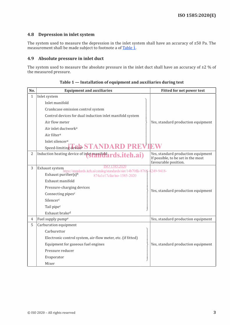
4.8 Depression in inlet system
The system used to measure the depression in the inlet system shall have an accuracy of ±50 Pa. The measurement shall be made subject to footnote a of Table 1.
4.9 Absolute pressure in inlet duct
The system used to measure the absolute pressure in the inlet duct shall have an accuracy of ±2 % of the measured pressure.
Table 1 — Installation of equipment and auxiliaries during test
No. Equipment and auxiliaries Fitted for net power test1 Inlet system
Inlet manifold Crankcase emission control system Control devices for dual induction inlet manifold system Air flow meter Air inlet ductworka
Air filtera
Inlet silencera
Speed-limiting devicea
Yes, standard production equipment
2 Induction heating device of inlet manifold
Yes, standard production equipment If possible, to be set in the most favourable position.
3 Exhaust system Exhaust purifier(s)b
Exhaust manifold Pressure-charging devices Connecting pipesc
Silencerc
Tail pipec
Exhaust braked
Yes, standard production equipment
4 Fuel supply pumpe Yes, standard production equipment5 Carburation equipment
Carburettor Electronic control system, air-flow meter, etc. (if fitted) Equipment for gaseous fuel engines Pressure reducer Evaporator Mixer
Yes, standard production equipment
© ISO 2020 – All rights reserved 3
iTeh STANDARD PREVIEW(standards.iteh.ai)
ISO 1585:2020https://standards.iteh.ai/catalog/standards/sist/14b70ffa-8765-4249-9418-
874a1e17cfae/iso-1585-2020

ISO 1585:2020(E)
No. Equipment and auxiliaries Fitted for net power test6 Fuel injection equipment [spark-ignition and compression
ignition (diesel)] Prefilter Filter Pump High-pressure pipe Injector Air inlet valve (if fitted)f
Electronic control system, etc. (if fitted) Governor/control system: automatic full-load stop for the control depending on atmospheric conditions
Yes, standard production equipment
7 Liquid cooling equipment Radiator Fang,h
Fan cowl Water pump Thermostat or thermal management systemi
Yes, standard production equipment
8 Air cooling Cowl Fan or blowerg,h
Temperature regulating device
Yes, standard production equipment
9 Electrical or electronic equipment Generator/alternatorj
Spark distribution system Coil(s) Wiring Spark-plugs Electronic control system including knock sensor/spark retard systemm
Yes, standard production equipment
10 Pressure-charging equipment (if fitted) Compressor driven either directly by the engine, and/or by the exhaust gases Boost controln
Charge-air-coolerg,h,k
Coolant pump or fan(engine-driven) Coolant flow control devices (if fitted)
Yes, standard production equipment
11 Auxiliary test bed fan Yes, if necessary12 Anti-pollution devicesl Yes, standard production equipment
Table 1 (continued)
4 © ISO 2020 – All rights reserved
iTeh STANDARD PREVIEW(standards.iteh.ai)
ISO 1585:2020https://standards.iteh.ai/catalog/standards/sist/14b70ffa-8765-4249-9418-
874a1e17cfae/iso-1585-2020

ISO 1585:2020(E)
No. Equipment and auxiliaries Fitted for net power testa The air induction system begins where the air enters the system from atmosphere. Except when there is a risk of the system having a noticeable influence upon engine power, an equivalent system may be used. In this case, a check should be made to ascertain that inlet depression does not differ by more than 100 Pa from the limit specified by the manufacturer for a clean air filter.b For the case of an exhaust particulate filter, the filter or equivalent restriction shall represent the clean state.c Except when there is a risk of the system having a noticeable influence upon engine power, an equivalent system may be used. In this case, a check should be made to ascertain that the backpressure in the engine ex-haust system does not differ by more than 1 000 Pa from that specified by the manufacturer.d If an exhaust brake is incorporated in the engine, the throttle valve shall be fixed fully open.e The fuel feed pressure may be adjusted, if necessary, to reproduce the inlet pump pressure conditions consist-ent with the particular engine application (particularly where a "fuel return" system, e.g. to tank or filter, is used).f The air inlet valve is the control valve for the pneumatic governor of the injection pump. The governor of the fuel injection equipment may contain other devices which may affect the amount of fuel injected.g The radiator, fan, fan cowl, water pump and thermostat shall be located on the test bed in the same relative positions that they will occupy on the vehicle. The cooling liquid circulation shall be operated by the engine water pump only.Cooling of the liquid may be produced either by the engine radiator or by an external circuit, provided that the pressure loss of this circuit and the pressure at the pump inlet remain substantially the same as those of the engine cooling system. The radiator shutter, if incorporated, shall be in the open position.Where the fan, radiator and cowl system cannot conveniently be fitted to the engine, the power absorbed by the fan when separately mounted in its correct position in relation to the radiator and cowl (if used), shall be determined at the speeds corresponding to the engine speeds used for measurement of the engine power either by calculation from standard characteristics or by practical tests. This power corrected to the standard atmospheric conditions defined in 6.2 shall be deducted from the corrected power.h Where a separate disconnectable or progressive fan or blower is incorporated, the test shall be made with the disconnectable fan or blower disconnected or with the progressive fan running at the maximum slip.i The thermostat may be fixed in the fully open position. For the case of an active thermal management sys-tem, control settings shall be representative of full load operation.j Minimum power of the generator/alternator: the power of the generator/alternator shall be limited to that necessary for the operation of accessories which are indispensable for engine operation. If the connection of a battery is necessary, a fully charged battery in good order shall be used.k Charge-air-cooled engines shall be tested complete with charge-air-cooling whether liquid or air-cooled but if the engine manufacturer prefers, a test bed system may replace the air-cooled cooler. In either case, the measurement of power at each speed shall be made with the pressure drop and temperature drop of the engine air across the charge air cooler in the test bed the same as those specified by the manufacturer for the system on the complete vehicle.If a test bed system is used on a compression-ignition engine without a wastegate, or with the wastegate not operating, the correction factor given in 6.3.2.1 b) is to be used. If a wastegate is both fitted and operating, then the correction factor in 6.3.2.1 a) is to be used.l They may include for example EGR system, catalytic converter, particulate filter, thermal reactor, secondaryair supply system and fuel evaporating protecting system.m The spark advance shall be representative of in-use conditions established with the minimum octane fuel recommended by the manufacturer.n For engines equipped with variable boost as a function of charge or inlet air temperature, octane rating and/or engine speed, the boost pressure shall be representative of in-vehicle conditions established with the mini-mum octane fuel as recommended by the manufacturer.
Table 1 (continued)
© ISO 2020 – All rights reserved 5
iTeh STANDARD PREVIEW(standards.iteh.ai)
ISO 1585:2020https://standards.iteh.ai/catalog/standards/sist/14b70ffa-8765-4249-9418-
874a1e17cfae/iso-1585-2020

ISO 1585:2020(E)
5 Tests
5.1 Auxiliaries
5.1.1 Auxiliariestobefitted
During the test, auxiliaries necessary to make an engine acceptable for service in the intended application (as listed in Table 1) shall be installed on the test bed as far as possible in the same position as in the intended application.
5.1.2 Auxiliaries to be removed
Certain vehicle accessories necessary only for the operation of the vehicle, and which may be mounted on the engine, shall be removed for the test. The following non-exhaustive list is given as an example:
— air compressor for brakes;
— power steering pump;
— suspension compressor;
— air-conditioning system compressor.
Where accessories cannot be removed, the power absorbed by them in the unloaded condition may be determined and added to the measured engine power.
5.1.3 Compression-ignition engine starting auxiliaries
For auxiliaries used to start compression-ignition engines, the two following cases shall be considered:
a) electrical starting: the generator/alternator is fitted and supplies, where necessary, electricity tothe accessories indispensable to the operation of the engine;
b) starting other than electrical: if there are any electrically operated accessories indispensable to theoperation of the engine, the generator/alternator is fitted to supply these accessories; otherwise, itis removed.
In either case, the system for producing and accumulating the energy necessary for starting is fitted and operates in the unloaded condition.
5.2 Setting conditions
The setting conditions for the test for determination of net power are indicated in Table 2.
Table 2 — Setting conditions
1 Setting of fuel delivery system
In accordance with the manufacturer's production specifications and used without further alteration for the particular application.
2 Setting of injection pump delivery system3 Ignition or injection timing (timing curve)4 Governor setting5 Anti-pollution devices6 Boost control
6 © ISO 2020 – All rights reserved
iTeh STANDARD PREVIEW(standards.iteh.ai)
ISO 1585:2020https://standards.iteh.ai/catalog/standards/sist/14b70ffa-8765-4249-9418-
874a1e17cfae/iso-1585-2020
ISO 1585:2020(E)
5.3 Test conditions
5.3.1 The net power test shall consist of a run at full throttle for spark-ignition engines and at the fixed full-load fuel injection pump setting for compression-ignition engines, the engine being equipped as specified in Table 1.
5.3.2 Performance data shall be obtained under stabilized operating conditions, with an adequate fresh air supply to the engine.
Engines shall have been run-in, started and warmed up in accordance with the manufacturer's recommendations. Combustion chambers may contain deposits, but in limited quantity. Test conditions such as inlet air temperature shall be selected as near to reference conditions (see 6.2) as possible in order to minimise the correction factor.
5.3.3 The temperature of the inlet air to the engine (ambient air), shall be measured within 0,15 m upstream of the air inlet duct work.
The thermometer or thermocouple shall be shielded from radiant heat and located directly in the airstream. It shall also be shielded from fuel spray back. A sufficient number of locations shall be used to give a representative average inlet temperature.
5.3.4 The inlet depression shall be measured downstream of the entry ducts, air filter, inlet silencer, speed-limiting device (if they are fitted) or their equivalents.
5.3.5 The absolute pressure at the entry to the engine, downstream of the compressor and heat exchanger, if they are fitted, shall be measured in the inlet manifold and at any other point where pressure has to be measured to calculate correction factors.
5.3.6 The exhaust back pressure shall be measured at a point at least three pipe diameters from the outlet flange(s) of the exhaust manifold(s) and downstream of the turbocharger(s), if fitted. The location shall be specified.
5.3.7 No data shall be taken until torque, speed and temperature have been maintained substantially constant for at least 1 min.
5.3.8 The engine speed during a run or reading shall not deviate from the selected speed by more than ±1 % or ±10 min–1, whichever is greater.
5.3.9 Observed brake load, fuel flow and inlet air temperature data shall be taken virtually simultaneously and shall, in each case, be the average of two stabilized consecutive readings which do not vary more than 2 % for the brake load and fuel consumption. The second reading shall be determined without any adjustment of the engine, approximately 1 min after the first.
5.3.10 The coolant temperature at the engine outlet shall be kept within ±5 K of the upper thermostatically controlled temperature specified by the manufacturer. If no temperature is specified, the temperature shall be 353 K ± 5 K.
For air-cooled engines, the temperature at a point indicated by the manufacturer shall be kept within 0
20−K of the maximum value specified by the manufacturer in the reference conditions.
5.3.11 Fuel temperature shall be as follows:
a) For spark-ignition engines, the fuel temperature shall be measured as near as possible to the inletof the carburettor or assembly of fuel injectors. Fuel temperature shall be maintained within ±5 Kof the temperature specified by the manufacturer. However, the minimum test fuel temperature
© ISO 2020 – All rights reserved 7
iTeh STANDARD PREVIEW(standards.iteh.ai)
ISO 1585:2020https://standards.iteh.ai/catalog/standards/sist/14b70ffa-8765-4249-9418-
874a1e17cfae/iso-1585-2020