Embed Size (px)
Citation preview
INTERNATIONALSTANDARD
ISO14403
First edition2002-03-01
Reference numberISO 14403:2002(E)
© ISO 2002
Water quality — Determination of total cyanide and free cyanide by continuous flow analysis
Qualité de l'eau — Dosage des cyanures totaux et des cyanures libres par analyse en flux continu
Copyright International Organization for Standardization Provided by IHS under license with ISO
Not for ResaleNo reproduction or networking permitted without license from IHS
--`,,`,-`-`,,`,,`,`,,`---
ISO 14403:2002(E)
ii © ISO 2002 – All rights reserved
PDF disclaimer
This PDF file may contain embedded typefaces. In accordance with Adobe's licensing policy, this file may be printed or viewed but shall not beedited unless the typefaces which are embedded are licensed to and installed on the computer performing the editing. In downloading this file,parties accept therein the responsibility of not infringing Adobe's licensing policy. The ISO Central Secretariat accepts no liability in this area.
Adobe is a trademark of Adobe Systems Incorporated.
Details of the software products used to create this PDF file can be found in the General Info relative to the file; the PDF-creation parameterswere optimized for printing. Every care has been taken to ensure that the file is suitable for use by ISO member bodies. In the unlikely eventthat a problem relating to it is found, please inform the Central Secretariat at the address given below.
© ISO 2002
All rights reserved. Unless otherwise specified, no part of this publication may be reproduced or utilized in any form or by any means,electronic or mechanical, including photocopying and microfilm, without permission in writing from either ISO at the address below or ISO'smember body in the country of the requester.
ISO copyright officeCase postale 56 • CH-1211 Geneva 20Tel. + 41 22 749 01 11Fax + 41 22 749 09 47E-mail [email protected] www.iso.ch
Printed in Switzerland
Copyright International Organization for Standardization Provided by IHS under license with ISO
Not for ResaleNo reproduction or networking permitted without license from IHS
--`,,`,-`-`,,`,,`,`,,`---
ISO 14403:2002(E)
© ISO 2002 – All rights reserved iii
Contents Page
1 Scope ............................................................................................................................................................... 1
2 Normative references ....................................................................................................................................... 1
3 Terms and definitions ........................................................................................................................................ 1
4 Interferences ..................................................................................................................................................... 2
5 Principle ............................................................................................................................................................ 2
6 Reagents .......................................................................................................................................................... 3
7 Apparatus ......................................................................................................................................................... 5
8 Sampling and sample preparation .................................................................................................................... 9
9 Procedure ....................................................................................................................................................... 10
10 Calculation .................................................................................................................................................... 12
11 Precision and accuracy ................................................................................................................................ 13
12 Test report .................................................................................................................................................... 13
Annexes
A Determination of the actual cyanide concentration in potassium cyanide stock solution................................ 14
B Example for the determination of total cyanide and free cyanide by continuous flow analysis (CFA) with gas diffusion and amperometric detection ................................................................................................................... 15
C Results of the interlaboratory trial for cyanide determination.......................................................................... 17
Bibliography........................................................................................................................................................... 18
Copyright International Organization for Standardization Provided by IHS under license with ISO
Not for ResaleNo reproduction or networking permitted without license from IHS
--`,,`,-`-`,,`,,`,`,,`---
ISO 14403:2002(E)
iv © ISO 2002 – All rights reserved
Foreword
ISO (the International Organization for Standardization) is a worldwide federation of national standards bodies (ISOmember bodies). The work of preparing International Standards is normally carried out through ISO technicalcommittees. Each member body interested in a subject for which a technical committee has been established hasthe right to be represented on that committee. International organizations, governmental and non-governmental, inliaison with ISO, also take part in the work. ISO collaborates closely with the International ElectrotechnicalCommission (IEC) on all matters of electrotechnical standardization.
International Standards are drafted in accordance with the rules given in the ISO/IEC Directives, Part 3.
Draft International Standards adopted by the technical committees are circulated to the member bodies for voting.Publication as an International Standard requires approval by at least 75 % of the member bodies casting a vote.
Attention is drawn to the possibility that some of the elements of this International Standard may be the subject ofpatent rights. ISO shall not be held responsible for identifying any or all such patent rights.
International Standard ISO 14403 was prepared by Technical Committee ISO/TC 147, Water quality, SubcommitteeSC 2, Physical, chemical, biochemical methods.
Annex A forms a normative part of this International Standard. Annexes B and C are for information only.
Copyright International Organization for Standardization Provided by IHS under license with ISO
Not for ResaleNo reproduction or networking permitted without license from IHS
--`,,`,-`-`,,`,,`,`,,`---
ISO 14403:2002(E)
© ISO 2002 – All rights reserved v
Introduction
Methods using flow analysis automate wet chemical procedures and are particularly suitable for the processing ofmany analytes in water in large sample series at a high analysis frequency.
Analysis can be performed by flow injection analysis (FIA) or continuous flow analysis (CFA). In this InternationalStandard the latter is specified. The CFA method shares the feature of an automatic dosage of the sample into a flowsystem (manifold) where the analytes in the sample react with the reagent solutions on their way through themanifold. The sample preparation may be integrated in the manifold. The reaction product is measured in a flowdetector (e.g. flow photometer).
It is absolutely essential that the test described in this International Standard be carried out by suitable qualified staff.It should be investigated whether and to what extend particular problems will require the specification of additionalmarginal conditions.
Copyright International Organization for Standardization Provided by IHS under license with ISO
Not for ResaleNo reproduction or networking permitted without license from IHS
--`,,`,-`-`,,`,,`,`,,`---

Copyright International Organization for Standardization Provided by IHS under license with ISO
Not for ResaleNo reproduction or networking permitted without license from IHS
--`,,`,-`-`,,`,,`,`,,`---
INTERNATIONAL STANDARD ISO 14403:2002(E)
© ISO 2002 – All rights reserved 1
Water quality — Determination of total cyanide and free cyanide by continuous flow analysis
WARNING — Persons using this International Standard should be familiar with normal laboratory practice.This International Standard does not purport to address all of the safety problems, if any, associated with itsuse. It is the responsibility of the user to establish appropriate safety and health practices and to ensurecompliance with any national regulatory conditions.
1 Scope
This International Standard specifies methods for the determination of cyanide in various types of water (such asground, drinking, surface, leachate and waste water) with cyanide concentrations usually above expressed ascyanide ions. The CFA method is applicable to a mass concentration range from to . The range ofapplication may be changed by varying the operation conditions.
NOTE Seawater may be analyzed with changes in sensitivity and adaptation of the reagent and calibration solutions to thesalinity of the samples.
2 Normative references
The following normative documents contain provisions which, through reference in this text, constitute provisions ofthis International Standard. For dated references, subsequent amendments to, or revisions of, any of thesepublications do not apply. However, parties to agreements based on this International Standard are encouraged toinvestigate the possibility of applying the most recent editions of the normative documents indicated below. Forundated references, the latest edition of the normative document referred to applies. Members of ISO and IECmaintain registers of currently valid International Standards.
ISO 3696:1987, Water for analytical laboratory use — Specification and test methods
ISO 5725-2:1994, Accuracy (trueness and precision) of measurement methods and results — Part 2: Basic methodfor the determination of repeatability and reproducibility of a standard measurement method
ISO 8466-1:1990, Water quality — Calibration and evaluation of analytical methods and estimation of performancecharacteristics — Part 1: Statistical evaluation of the linear calibration function
3 Terms and definitions
For the purposes of this International Standard, the following terms and definitions apply.
3.1
total cyanide
sum of some organically bound cyanides, free cyanide ions, complex compounds and cyanide bound in simple metalcyanides, with the exception of cyanide bound in cobalt complexes and of thiocyanate
3 µg/l10 µg/l 100 µg/l
Copyright International Organization for Standardization Provided by IHS under license with ISO
Not for ResaleNo reproduction or networking permitted without license from IHS
--`,,`,-`-`,,`,,`,`,,`---
ISO 14403:2002(E)
2 © ISO 2002 – All rights reserved
3.2
free cyanide
easily liberatable cyanide
sum of cyanide ions and the cyanide bound in simple metal cyanides as determined in accordance with thisInternational Standard
NOTE Organic cyanides are not included.
4 Interferences
4.1 Interferences by oxidizing agents
Oxidizing agents such as chlorine decompose most of the cyanides. If oxidizing agents are suspected, test for theirpresence as given in clause 8.
4.2 Interferences by sulfides
Sulfide concentrations affect the colorimetric procedure. If sulfide is suspected, carry out tests for itspresence as given in clause 8.
4.3 Other interferences
When using in-line distillation for separation of the hydrogen cyanide, salt concentrations higher than cancause clogging of the distillation coil. Dilute these samples prior to measurement in order to overcome this problem.
Under the given distillation conditions aldehydes can transform cyanide to nitrite. Aldehydes can be removed byadding silver nitrate to the sample.
NOTE The addition of AgNO3 can alter the ratio of the concentrations of free and total cyanide. The user should evaluate thisprocedure.
Particulate matter in the sample may lead to clogging of the transport tubes and will interfere with the photometricmeasurement. Particles should be removed by filtration.
Thiocyanate can slightly interfere and lead to positive bias (9.3.2). Significant interferences can arise from cyanideimpurities in thiocyanate or from inappropriate distillation procedures (7.1).
5 Principle
5.1 Determination of total cyanide concentration
Complex bound cyanide is decomposed by UV light in a continuous flow at a pH of 3,8. A UV-B lamp ( ) and adecomposition spiral of borosilicate glass is used to filter off UV light with a wavelength of thus preventing theconversion of thiocyanate into cyanide. Alternatively it is possible to use a long wavelength UV lamp ( ), whichdoes not emit light below and which is equipped with a decomposition spiral of quartz glass orpolytetrafluoroethylene (PTFE). The hydrogen cyanide present at pH 3,8 is separated by on-line distillation at or by gas diffusion at across a hydrophobic membrane. The hydrogen cyanide is then determinedphotometrically by the reaction of cyanide with chloramine-T to cyanogen chloride. This reacts with pyridine-4-carbonic acid and 1,3-dimethylbarbituric acid to give a red dye.
> 60 mg/l
10 g/l
> 0,1 mm
312 nm290 nm
351 nm290 nm
125 ◦C30 ◦C
Copyright International Organization for Standardization Provided by IHS under license with ISO
Not for ResaleNo reproduction or networking permitted without license from IHS
--`,,`,-`-`,,`,,`,`,,`---
ISO 14403:2002(E)
© ISO 2002 – All rights reserved 3
5.2 Determination of free cyanide concentration
The UV lamp is switched off when determining the free cyanide content. During distillation at pH 3,8 for separation ofthe hydrogen cyanide present, a zinc sulfate solution is added to the sample flow in order to precipitate any ironcyanides present as the zinc-cyanoferrate complex. For detection see 5.1.
6 Reagents
WARNING — KCN, K2Zn(CN)4, and their solutions and wastes are toxic. Waste containing these substancesshall be removed appropriately.
Use only reagents of recognized analytical grade.
6.1 Water, grade 1 according to ISO 3696.
6.2 Hydrochloric acid I, .
6.3 Hydrochloric acid II, .
6.4 Hydrochloric acid III, .
6.5 Sodium hydroxide solution I, .
6.6 Sodium hydroxide solution II, .
6.7 Sodium hydroxide solution III, .
6.8 Sodium hydroxide solution IV, .
6.9 Surfactant, polyoxyethylene lauryl ether, OH-(CH2CH2-O)n-C18H37.
Add of polyoxyethylene lauryl ether in small quantities to of water (6.1) and mix well.
Alternatively use a commercially available solution of the surfactant.
6.10 Citric acid monohydrate, C6H8O7·H2O.
6.11 Zinc sulfate heptahydrate, ZnSO4·7H2O.
6.12 Potassium hydrogenphthalate, KHC8H4O4.
6.13 Chloramine-T trihydrate, C7H7ClNNaO2S·3H2O.
6.14 1,3-Dimethylbarbituric acid, C6H8N2O3.
6.15 Pyridine-4-carboxylic acid, C6H5NO2.
6.16 Potassium thiocyanate, KSCN.
6.17 Potassium hexacyanoferrate(III), K3Fe(CN)6.
6.18 Cyanide standards.
6.18.1 Potassium cyanide stock solution, (see annex A).
Dissolve of potassium cyanide, KCN, in sodium hydroxide solution IV (6.8) in a graduatedflask and make up to volume with sodium hydroxide solution IV (6.8).
c(HCl) = 12 mol/l
c(HCl) = 1 mol/l
c(HCl) = 0,1 mol/l
c(NaOH) = 2,5 mol/l
c(NaOH) = 1,0 mol/l
c(NaOH) = 0,1 mol/l
c(NaOH) = 0,01 mol/l
30 g 100 ml
KCN, ρ(CN) = 100 mg/l
250 mg± 1 mg 1 000 ml
Copyright International Organization for Standardization Provided by IHS under license with ISO
Not for ResaleNo reproduction or networking permitted without license from IHS
--`,,`,-`-`,,`,,`,`,,`---
ISO 14403:2002(E)
4 © ISO 2002 – All rights reserved
Alternatively, a potassium tetracyanozincate solution (6.18.2) may be used.
6.18.2 Potassium tetracyanozincate solution, K2Zn(CN)4, .
Commercially available.
6.18.3 Cyanide solution I, .
Pipette of the potassium tetracyanozincate solution I (6.18.2) or of the potassium cyanide stock solution(6.18.1) into a graduated flask and bring to volume with sodium hydroxide solution IV (6.8).
This solution is stable for 1 week if stored at room temperature.
6.18.4 Calibration solutions.
Prepare at least five calibration solutions with cyanide concentrations, equidistantly distributed over the workingrange, by appropriate dilution of the cyanide solution I (6.18.3). If, for example, six calibration solutions should beprepared, proceed as follows:
Pipette of the cyanide solution I (6.18.3) into a graduated flask and make up to volume with sodiumhydroxide solution IV (6.8).
Pipette, in graduated flasks, , , , , , or , respectively, of the above-mentioned cyanide solution and make up to volume with sodium hydroxide solution IV (6.8).
These solutions contain , , , , , and of cyanide, respectively (except forcorrections in the concentration found on titration of the potassium cyanide solution (6.18.1), (see annex A).
These solutions are stable for 2 days if stored in a refrigerator at to .
6.19 Reagents for the determination of cyanide.
6.19.1 Buffer (pH = 3,8) for distillation and gas diffusion method.
Dissolve of citric acid (6.10) in of water (6.1). Add of sodium hydroxide solution I (6.5) and, ifnecessary adjust to pH 3,8 with hydrochloric acid II (6.3) or sodium hydroxide solution II (6.6). Dilute to withwater.
This solution is stable for 3 months if stored in a refrigerator at to .
6.19.2 Zinc sulfate solution (only for distillation method).
Dissolve of zinc sulfate heptahydrate (6.11) in of water (6.1), mix and dilute to with water.
6.19.3 Recipient solution (only for gas diffusion).
Sodium hydroxide solution III (6.7).
6.19.4 Buffer solution for the final photometric determination ( ).
Dissolve of sodium hydroxide (NaOH) in of water (6.1). Add of potassium hydrogenphthalate(6.12) and dilute to approximately with water.
If necessary, adjust the pH of the solution to 5,2 with hydrochloric acid II (6.3) or sodium hydroxide solution II (6.6).
Add of surfactant (6.9) and make up to with water.
This solution is stable for 3 months if stored in a refrigerator at to .
ρ(CN) = 1 000 mg/l± 2 mg/l
ρ(CN) = 10 mg/l
1 ml 10 ml100 ml
10 ml 100 ml
100 ml 1 ml 3 ml 5 ml 6 ml 8 ml 10 ml 1 mg/l
10 µg/l 30 µg/l 50 µg/l 60 µg/l 80 µg/l 100 µg/l
2 ◦C 5 ◦C
50 g 350 ml 120 ml500 ml
2 ◦C 5 ◦C
10 g 750 ml 1 000 ml
pH = 5,2
2,3 g 500 ml 20,5 g975 ml
1 ml 1 000 ml
2 ◦C 5 ◦C
Copyright International Organization for Standardization Provided by IHS under license with ISO
Not for ResaleNo reproduction or networking permitted without license from IHS
--`,,`,-`-`,,`,,`,`,,`---
ISO 14403:2002(E)
© ISO 2002 – All rights reserved 5
6.19.5 Chloramine-T trihydrate solution.
Dissolve of chloramine-T trihydrate (6.13) in of water.
This solution is stable for 3 months if stored in a refrigerator at to .
6.19.6 Colour reagent.
Dilute of sodium hydroxide, NaOH, in of water (6.1). Add of 1,3-dimethylbarbituric acid(6.14), and of pyridine-4-carboxylic acid (6.15), and dilute to approximately with water (6.1).
If necessary, bring the solution to pH 5,2 with hydrochloric acid II (6.3) or sodium hydroxide solution II (6.6).
Make up to with water (6.1). Mix this solution intensively (e.g. by using a magnetic stirrer) for at and then filter over a pleated filter (e.g. hardened ashless paper).
This solution is stable for 3 months if stored in a refrigerator at to .
6.20 Standard thiocyanate solution, calculated cyanide concentration: .
Dissolve in a graduated flask of potassium thiocyanate (6.16) in sodium hydroxidesolution IV (6.8), and make up to volume with sodium hydroxide solution IV (6.8).
This solution is stable for 2 months if stored in a refrigerator at to .
6.21 Standard potassium hexacyanoferrate(III) solution (red blood alkaline salt).
Calculated cyanide concentration .
Dissolve in a graduated flask of potassium hexacyanoferrate(III) (6.17) in sodiumhydroxide solution IV (6.8), and make up to volume with sodium hydroxide solution IV (6.8).
This solution is stable for 2 months if stored in a refrigerator at to .
6.22 Rinsing solution.
Dissolve of surfactant (6.9) in of water.
6.23 Ascorbic acid, C6H8O6.
6.24 Powdered lead carbonate, PbCO3.
7 Apparatus
Usual laboratory apparatus, and
7.1 Continuous flow analysis system for distillation method
A typical system comprises the following components (see Figure 1).
7.1.1 Autosampler, or another device capable of introducing sample reproducibility.
7.1.2 Reagent reservoirs.
7.1.3 Low pulsation pump, having specific chemically inert pump tubes, for flow rates as given in Figure 1 as anexample.
2,0 g± 0,05 g 1 000 ml
2 ◦C 5 ◦C
7,0 g 500 ml 16,8 g± 0,1 g13,6 g± 0,1 g 975 ml
1 000 ml 1 h 30 ◦C
2 ◦C 5 ◦C
ρ(CN) = 100 mg/l
1 000 ml 373 mg± 1 mg
2 ◦C 5 ◦C
ρ(CN) = 10 mg/l
1 000 ml 21,1 mg± 0,1 mg
2 ◦C 5 ◦C
2 ml 1 000 ml
Copyright International Organization for Standardization Provided by IHS under license with ISO
Not for ResaleNo reproduction or networking permitted without license from IHS
--`,,`,-`-`,,`,,`,`,,`---
ISO 14403:2002(E)
6 © ISO 2002 – All rights reserved
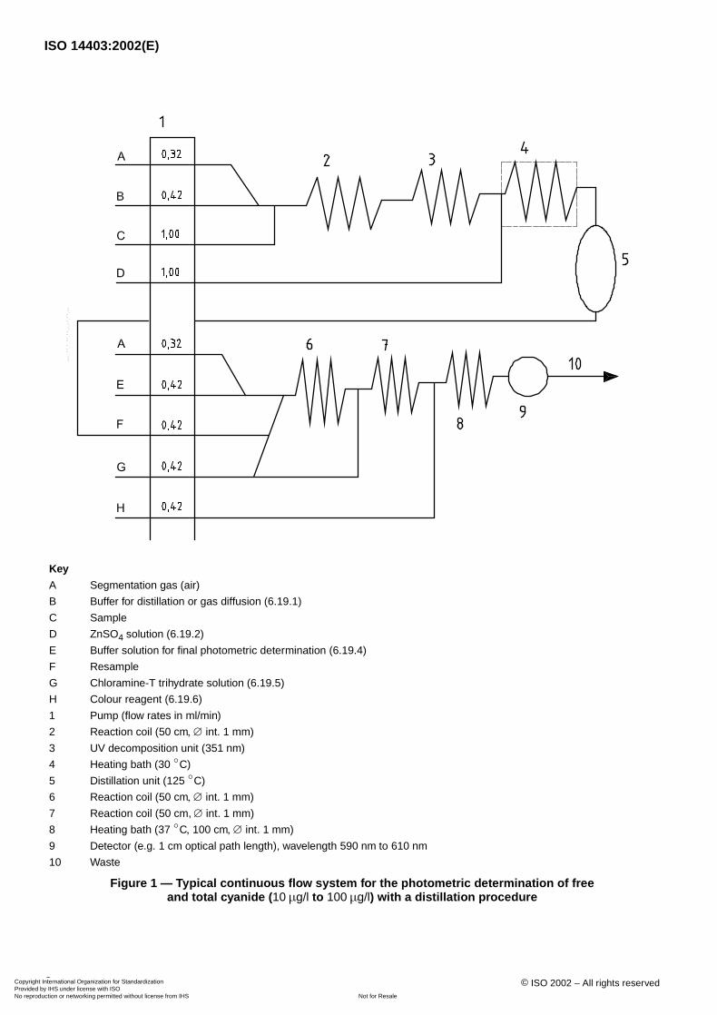
Key
A Segmentation gas (air)
B Buffer for distillation or gas diffusion (6.19.1)
C Sample
D ZnSO4 solution (6.19.2)
E Buffer solution for final photometric determination (6.19.4)
F Resample
G Chloramine-T trihydrate solution (6.19.5)
H Colour reagent (6.19.6)
1 Pump (flow rates in )
2 Reaction coil ( , ∅ int. )
3 UV decomposition unit ( )
4 Heating bath ( )
5 Distillation unit ( )
6 Reaction coil ( , ∅ int. )
7 Reaction coil ( ∅ int. )
8 Heating bath ( , , ∅ int. )
9 Detector (e.g. optical path length), wavelength to
10 Waste
Figure 1 — Typical continuous flow system for the photometric determination of free and total cyanide ( to ) with a distillation procedure
ml/min
50 cm 1 mm
351 nm
30 ◦C
125 ◦C
50 cm 1 mm
50 cm, 1 mm
37 ◦C 100 cm 1 mm
1 cm 590 nm 610 nm
10 µg/l 100 µg/l
Copyright International Organization for Standardization Provided by IHS under license with ISO
Not for ResaleNo reproduction or networking permitted without license from IHS
--`,,`,-`-`,,`,,`,`,,`---
ISO 14403:2002(E)
© ISO 2002 – All rights reserved 7
7.1.4 UV lamp, consisting of one of the following.
a) UV lamp with an emission maximum of , bandwidth , and a power of to , and a digestioncoil made of quartz glass or PTFE with a capacity of approximately (e.g. 30 or 60 turns with a diameter of
, a tube wall thickness of max. and an internal diameter of or ).
b) UV-B lamp with an emission maximum of and a power of to , and a digestion coil madeof borosilicate glass with a capacity of approximately (e.g. 45 turns with a diameter of , a tube wallthickness of max. and an internal diameter of ).
Make sure that no UV light with a wavelength below reaches the sample flow in order to avoid thedecomposition of thiocyanate to cyanide.
7.1.5 In-line distillation device, adjustable to a temperature of with a distillation coil of glass orpolymer material, length of spiral e.g. , internal diameter e.g. .
7.1.6 Manifold, capable of highly reproducible dosing of gas bubbles, sample and reagents, and having appropriatetransport systems and connection assemblies made of chemically inert glass, polymer or metal.
7.1.7 Heating bath, for colorimetric reaction, adjustable to a temperature of with a coil volume toallow a sample retention period of approximately .
7.1.8 Photometric detector, with a flow cell, and having a wavelength of range .
Use an appropriate optical path length to achieve a minimum absorbance (absolute value) of 0,01 for a cyanide solution.
7.1.9 Recording unit (e.g. strip chart recorder, integrator or printer/plotter). In general, peak height signals aremeasured.
7.2 Continuous flow analysis system for gas diffusion method
A typical system comprises the following components (see Figure 2).
7.2.1 Autosampler, or another device capable of introducing sample reproducibly.
7.2.2 Reagent reservoirs.
7.2.3 Low pulsation pump, having specific chemically inert pump tubes. Figure 2 shows an example of flow rates.
7.2.4 UV lamp, consisting of one of the following.
a) UV lamp with an emission maximum of , bandwidth , and a power of to and having adigestion coil made of quartz glass or PTFE with a capacity of approximately (e.g. 30 or 60 turns with adiameter of , a tube wall thickness of max. and an internal diameter of or ).
b) UV-B lamp with an emission maximum of and a power of to and having a digestion coilmade of borosilicate glass with a capacity of approximately (e.g. 45 turns with a diameter of , a tubewall thickness of max and an internal diameter of ).
Make sure that no UV light with a wavelength below reaches the sample flow in order to avoid thedecomposition of thiocyanate to cyanide.
7.2.5 Gas diffusion cell, having a hydrophobic semipermeable membrane made from, for example polypropene orPTFE, and having a typical thickness of to , with a pore size of to .
7.2.6 Two heating baths for gas-diffusion temperature stabilization, adjustable to with a coilcapacity of for example and internal diameter of for example .
351 nm 45 nm 8 W 12 W4 ml
30 mm 1 mm 1 mm 2 mm
312 nm± 5 nm 8 W 12 W13 ml 30 mm
1 mm 2 mm
290 nm
125 ◦C± 1 ◦C80 cm 1,5 mm
37 ◦C± 1 ◦C4 min
600 nm± 10 nm
10 µg/l
351 nm 45 nm 8 W 12 W4 ml
30 mm 1 mm 1 mm 2 mm
312 nm± 5 nm 8 W 12 W13 ml 30 mm
1 mm 2 mm
290 nm
90 µm 200 µm 0,1 µm 1 µm
30 ◦C± 1 ◦C2 ml 1 mm
Copyright International Organization for Standardization Provided by IHS under license with ISO
Not for ResaleNo reproduction or networking permitted without license from IHS
--`,,`,-`-`,,`,,`,`,,`---
ISO 14403:2002(E)
8 © ISO 2002 – All rights reserved
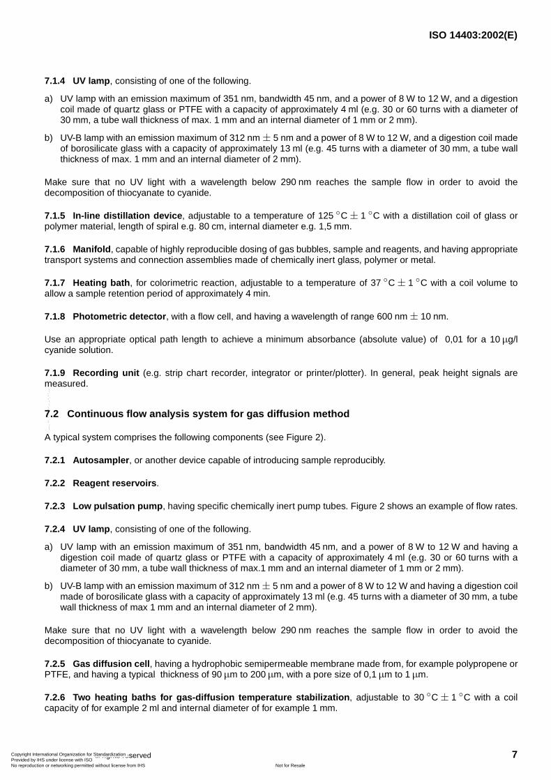
Key
A Segmentation gas (air)
B Sample
C Buffer for distillation or gas diffusion (6.19.1)
D Recipient solution for gas diffusion (6.19.3)
E Buffer solution for final photometric determination (6.19.4)
F Chloramine-T trihydrate solution (6.19.5)
G Colour reagent (6.19.6)
1 Pump (flow rates in )
2 Reaction coil ( , ∅ int. )
3 UV decomposition unit ( , , ∅ int. )
4 Heating bath ( , , ∅ int. )
5 Gas diffusion unit
6 Reaction coil ( , ∅ int. )
7 Reaction coil ( ∅ int. )
8 Heating bath ( , , ∅ int. )
9 Detector (e.g. optical path length), wave length to
10 Waste
Figure 2 — Typical continuous flow system for the photometric determination of free and total cyanide ( to ) with gas-diffusion separation
ml/min
50 cm 1 mm
315 nm 420 cm 2 mm
30 ◦C 50 cm 1 mm
50 cm 1 mm
50 cm, 1 mm
37 ◦C 50 cm 1 mm
1 cm 590 nm 610 nm
10 µg/l 100 µg/l
Copyright International Organization for Standardization Provided by IHS under license with ISO
Not for ResaleNo reproduction or networking permitted without license from IHS
--`,,`,-`-`,,`,,`,`,,`---
ISO 14403:2002(E)
© ISO 2002 – All rights reserved 9
7.2.7 Manifold, capable of producing highly reproducible dosing of gas bubbles, sample and reagents, and havingappropriate transport systems and connection assemblies made of chemically inert glass, polymer or metal.
7.2.8 Heating bath, for colorimetric reaction adjustable to a temperature of with a spiral dimension toallow a sample retention period of approximately .
7.2.9 Photometric detector, with a flow cell, and having a wavelength range of .
Use an appropriate optical path length to achieve a minimum absorbance (absolute value) of 0,01 for a cyanide solution.
7.2.10 Recording unit (e.g. strip chart recorder, integrator or printer/plotter). In general, peak height signals aremeasured.
7.3 Additional apparatus
7.3.1 Graduated flasks, with nominal capacities of , , and .
7.3.2 Lead acetate test paper (commercially available).
7.3.3 Pipettes, with nominal capacities of , , , , , and , or dispenser.
7.3.4 Beakers, with nominal capacities of , , and .
7.3.5 Membrane filter assembly, with membrane filters having a pore size of .
7.3.6 pH measuring device.
8 Sampling and sample preparation
8.1 Sample preparation
If necessary remove particles ( ) by membrane filtration immediately after sampling.
Bring the pH of the water samples to 12 with sodium hydroxide solutions I to IV (6.5 to 6.8) such that the quantity ofadded alkaline yields a negligible dilution of the sample.
Test for interferences and treat if necessary (see clause 4 and 8.2).
Analyze the sample in accordance with clause 9 as soon as possible after sampling, but at the latest within threedays. Store the sample in the dark.
8.2 Treatment for interferences
8.2.1 Oxidizing agents
In the case of oxidizing agents, treat the sample immediately after sampling. Test a drop of the sample withpotassium iodide-starch test paper (KI starch paper); a blue colour indicates the need for treatment. Add ascorbicacid (6.23), a few crystals at a time, until a drop of sample produces no colour on the indicator paper. Then add anadditional portion of of ascorbic acid for each of sample volume.
37 ◦C± 1 ◦C4 min
600 nm± 10 nm
10 µg/l
100 ml 250 ml 500 ml 1 000 ml
100 µl 1 ml 2 ml 5 ml 20 ml 50 ml 100 ml
25 ml 50 ml 100 ml 1 000 ml
0,45 µm
> 0,1 mm
0,6 g 1 000 ml
Copyright International Organization for Standardization Provided by IHS under license with ISO
Not for ResaleNo reproduction or networking permitted without license from IHS
--`,,`,-`-`,,`,,`,`,,`---
ISO 14403:2002(E)
10 © ISO 2002 – All rights reserved
8.2.2 Sulfides
If a drop of the sample on lead acetate test paper indicates the presence of sulfide, treat an additional of thestabilized sample ( ) than that required for the cyanide determination with powdered lead carbonate (6.24).
Lead sulfide precipitates if the sample contains sulfide.
Repeat this operation until a drop of the treated sample solution does not darken the lead acetate test paper.
Filter the solution through a dry filter paper into a dry beaker, and from the filtrate measure the sample to be used foranalysis. Avoid a large excess of lead and a long contact time in order to minimize loss by complexation or occlusionof cyanide on the precipitated material.
9 Procedure
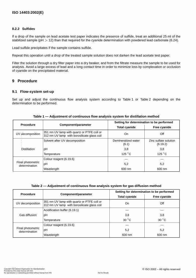
9.1 Flow-system set-up
Set up and adjust the continuous flow analysis system according to Table 1 or Table 2 depending on thedetermination to be performed.
Table 1 — Adjustment of continuous flow analysis system for distillation method
Procedure Component/parameterSetting for determination to be performed
Total cyanide Free cyanide
UV decomposition UV lamp with quartz or PTFE coil or UV lamp with borosilicate glass coil
On Off
Solvent after UV decomposition Demineralized water(6.1)
Zinc sulfate solution (6.19.2)
Distillation pH 3,8 3,8
Temperature
Final photometric determination
Colour reagent (6.19.6) — —
pH 5,2 5,2
Wavelength
Table 2 — Adjustment of continuous flow analysis system for gas diffusion method
Procedure Component/parameterSetting for determination to be performed
Total cyanide Free cyanide
UV decomposition UV lamp with quartz or PTFE coil or UV lamp with borosilicate glass coil
On Off
Gas diffusion
Acidification buffer (6.19.1) — —
pH 3,8 3,8
Temperature
Final photometric determination
Colour reagent (6.19.6) — —
pH 5,2 5,2
Wavelength
25 mlpH > 12
351 nm312 nm
125 ◦C 125 ◦C
600 nm 600 nm
351 nm312 nm
30 ◦C 30 ◦C
600 nm 600 nm
Copyright International Organization for Standardization Provided by IHS under license with ISO
Not for ResaleNo reproduction or networking permitted without license from IHS
--`,,`,-`-`,,`,,`,`,,`---
ISO 14403:2002(E)
© ISO 2002 – All rights reserved 11
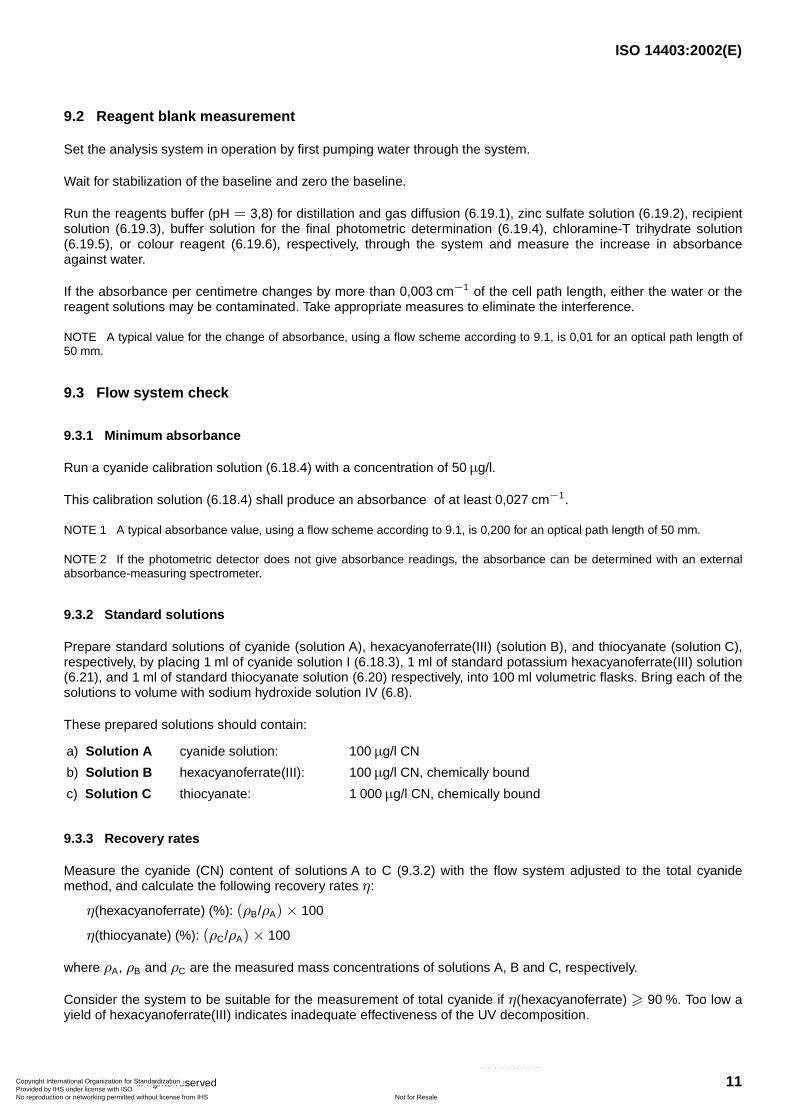
9.2 Reagent blank measurement
Set the analysis system in operation by first pumping water through the system.
Wait for stabilization of the baseline and zero the baseline.
Run the reagents buffer ( ) for distillation and gas diffusion (6.19.1), zinc sulfate solution (6.19.2), recipientsolution (6.19.3), buffer solution for the final photometric determination (6.19.4), chloramine-T trihydrate solution(6.19.5), or colour reagent (6.19.6), respectively, through the system and measure the increase in absorbanceagainst water.
If the absorbance per centimetre changes by more than of the cell path length, either the water or thereagent solutions may be contaminated. Take appropriate measures to eliminate the interference.
NOTE A typical value for the change of absorbance, using a flow scheme according to 9.1, is 0,01 for an optical path length of.
9.3 Flow system check
9.3.1 Minimum absorbance
Run a cyanide calibration solution (6.18.4) with a concentration of .
This calibration solution (6.18.4) shall produce an absorbance of at least .
NOTE 1 A typical absorbance value, using a flow scheme according to 9.1, is 0,200 for an optical path length of .
NOTE 2 If the photometric detector does not give absorbance readings, the absorbance can be determined with an externalabsorbance-measuring spectrometer.
9.3.2 Standard solutions
Prepare standard solutions of cyanide (solution A), hexacyanoferrate(III) (solution B), and thiocyanate (solution C),respectively, by placing of cyanide solution I (6.18.3), of standard potassium hexacyanoferrate(III) solution(6.21), and of standard thiocyanate solution (6.20) respectively, into volumetric flasks. Bring each of thesolutions to volume with sodium hydroxide solution IV (6.8).
These prepared solutions should contain:
9.3.3 Recovery rates
Measure the cyanide (CN) content of solutions A to C (9.3.2) with the flow system adjusted to the total cyanidemethod, and calculate the following recovery rates :
(hexacyanoferrate) ( ):
(thiocyanate) ( ):
where , and are the measured mass concentrations of solutions A, B and C, respectively.
Consider the system to be suitable for the measurement of total cyanide if (hexacyanoferrate) . Too low ayield of hexacyanoferrate(III) indicates inadequate effectiveness of the UV decomposition.
a) Solution A cyanide solution: CN
b) Solution B hexacyanoferrate(III): CN, chemically bound
c) Solution C thiocyanate: CN, chemically bound
pH = 3,8
0,003 cm−1
50 mm
50 µg/l
0,027 cm−1
50 mm
1 ml 1 ml1 ml 100 ml
100 µg/l
100 µg/l
1 000 µg/l
η
η % (ρB/ρA)× 100
η % (ρC/ρA)× 100
ρA ρB ρC
η � 90 %
Copyright International Organization for Standardization Provided by IHS under license with ISO
Not for ResaleNo reproduction or networking permitted without license from IHS
--`,,`,-`-`,,`,,`,`,,`---
ISO 14403:2002(E)
12 © ISO 2002 – All rights reserved
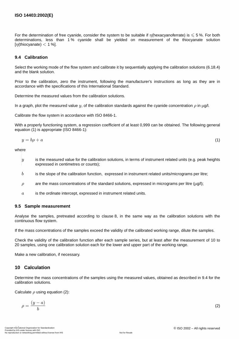
For the determination of free cyanide, consider the system to be suitable if (hexacyanoferrate) is . For bothdeterminations, less than cyanide shall be yielded on measurement of the thiocyanate solution[ (thiocyanate) ].
9.4 Calibration
Select the working mode of the flow system and calibrate it by sequentially applying the calibration solutions (6.18.4)and the blank solution.
Prior to the calibration, zero the instrument, following the manufacturer’s instructions as long as they are inaccordance with the specifications of this International Standard.
Determine the measured values from the calibration solutions.
In a graph, plot the measured value , of the calibration standards against the cyanide concentration in .
Calibrate the flow system in accordance with ISO 8466-1.
With a properly functioning system, a regression coefficient of at least 0,999 can be obtained. The following generalequation (1) is appropriate (ISO 8466-1):
(1)
where
is the measured value for the calibration solutions, in terms of instrument related units (e.g. peak heightsexpressed in centimetres or counts);
is the slope of the calibration function, expressed in instrument related units/micrograms per litre;
are the mass concentrations of the standard solutions, expressed in micrograms per litre ( );
is the ordinate intercept, expressed in instrument related units.
9.5 Sample measurement
Analyse the samples, pretreated according to clause 8, in the same way as the calibration solutions with thecontinuous flow system.
If the mass concentrations of the samples exceed the validity of the calibrated working range, dilute the samples.
Check the validity of the calibration function after each sample series, but at least after the measurement of 10 to20 samples, using one calibration solution each for the lower and upper part of the working range.
Make a new calibration, if necessary.
10 Calculation
Determine the mass concentrations of the samples using the measured values, obtained as described in 9.4 for thecalibration solutions.
Calculate using equation (2):
(2)
η � 5 %1 %
η < 1 %
y ρ µg/l
y = bρ+ a
y
b
ρ µg/l
a
ρ
ρ =(y − a)
b
Copyright International Organization for Standardization Provided by IHS under license with ISO
Not for ResaleNo reproduction or networking permitted without license from IHS
--`,,`,-`-`,,`,,`,`,,`---
ISO 14403:2002(E)
© ISO 2002 – All rights reserved 13
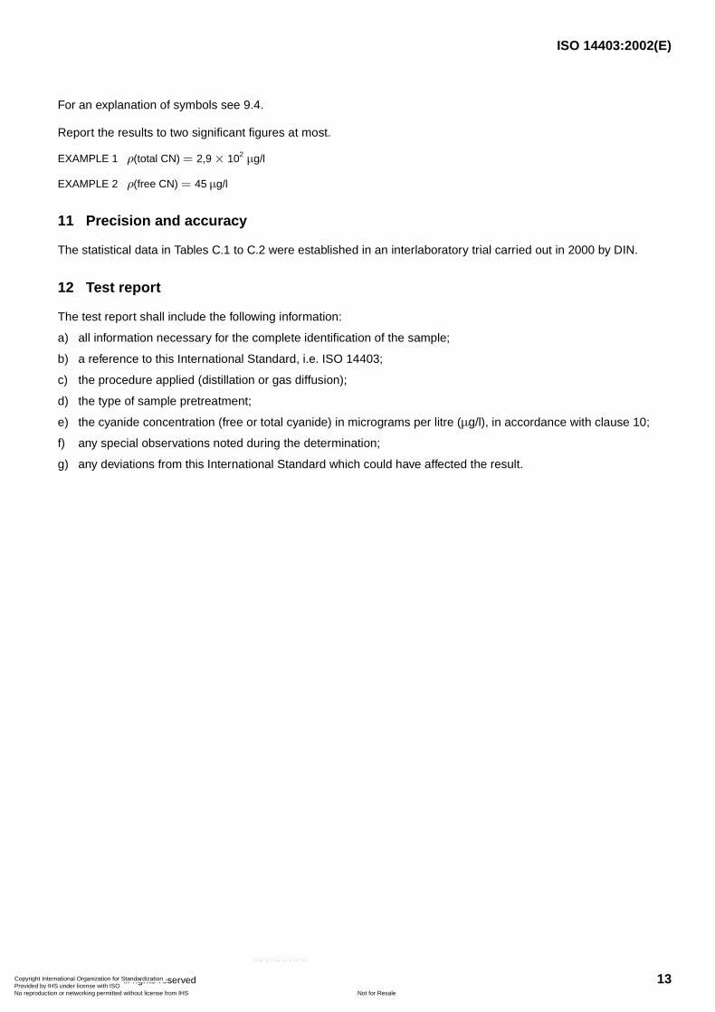
For an explanation of symbols see 9.4.
Report the results to two significant figures at most.
EXAMPLE 1 (total CN)
EXAMPLE 2 (free CN)
11 Precision and accuracy
The statistical data in Tables C.1 to C.2 were established in an interlaboratory trial carried out in 2000 by DIN.
12 Test report
The test report shall include the following information:
a) all information necessary for the complete identification of the sample;
b) a reference to this International Standard, i.e. ISO 14403;
c) the procedure applied (distillation or gas diffusion);
d) the type of sample pretreatment;
e) the cyanide concentration (free or total cyanide) in micrograms per litre ( ), in accordance with clause 10;
f) any special observations noted during the determination;
g) any deviations from this International Standard which could have affected the result.
ρ = 2,9× 10² µg/l
ρ = 45 µg/l
µg/l
Copyright International Organization for Standardization Provided by IHS under license with ISO
Not for ResaleNo reproduction or networking permitted without license from IHS
--`,,`,-`-`,,`,,`,`,,`---
ISO 14403:2002(E)
14 © ISO 2002 – All rights reserved
Annex A(normative)
Determination of the actual cyanide concentration in potassium cyanide stock solution
A.1 General
If KCN stock solution is used to prepare the cyanide calibration solutions (6.18.4), their concentrations shall becorrected using the following procedure.
A.2 Additional reagents
A.2.1 p-Dimethylaminobenzylidene rhodanine, C12H12N2OS2.
A.2.2 Indicator solution.
Dissolve of p-dimethylaminobenzylidene rhodanine (A.2.1) in of acetone (C3H6O).
This solution is stable for one week if stored in a refrigerator at to .
A.2.3 Silver nitrate solution, .
A.3 Determination of cyanide concentration in potassium cyanide solution
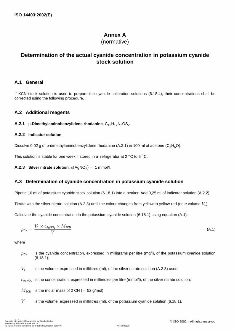
Pipette of potassium cyanide stock solution (6.18.1) into a beaker. Add of indicator solution (A.2.2).
Titrate with the silver nitrate solution (A.2.3) until the colour changes from yellow to yellow-red (note volume ).
Calculate the cyanide concentration in the potassium cyanide solution (6.18.1) using equation (A.1):
(A.1)
where
is the cyanide concentration, expressed in milligrams per litre (mg/l), of the potassium cyanide solution(6.18.1);
is the volume, expressed in millilitres (ml), of the silver nitrate solution (A.2.3) used;
is the concentration, expressed in millimoles per litre (mmol/l), of the silver nitrate solution;
is the molar mass of 2 CN ( );
is the volume, expressed in millilitres (ml), of the potassium cyanide solution (6.18.1).
0,02 g 100 ml
2 ◦C 5 ◦C
c(AgNO3) = 1 mmol/l
10 ml 0,25 ml
V1
ρCN =V1 × cAgNO3 ×M2CN
V
ρCN
V1
cAgNO3
M2CN = 52 g/mol
V
Copyright International Organization for Standardization Provided by IHS under license with ISO
Not for ResaleNo reproduction or networking permitted without license from IHS
--`,,`,-`-`,,`,,`,`,,`---
ISO 14403:2002(E)
© ISO 2002 – All rights reserved 15
Annex B(informative)
Example for the determination of total cyanide and free cyanide by continuous flow analysis (CFA) with gas diffusion and amperometric
detection
B.1 Principle
Amperometric detection may be used as an alternative to the photometric detection method. According to thisdetection, the use of toxic and hazardous substances is avoided and the sensitivity of the method for thedetermination of free and total cyanide is improved to the lower level.
Figure B.1 below shows a flow diagram for the determination of free and total cyanide with gas diffusion andamperometric detection. An appropriate combination of the distillation method with an amperometric detection is alsoapplicable.
See also references [6] to [10].
B.2 Apparatus
The amperometric detector may consist of:
— a working electrode: silver;
— a reference electrode: Ag/AgCl;
— an auxiliary electrode: platinum;
— the potential applied: .
µg/l
+0,1 V
Copyright International Organization for Standardization Provided by IHS under license with ISO
Not for ResaleNo reproduction or networking permitted without license from IHS
--`,,`,-`-`,,`,,`,`,,`---
ISO 14403:2002(E)
16 © ISO 2002 – All rights reserved
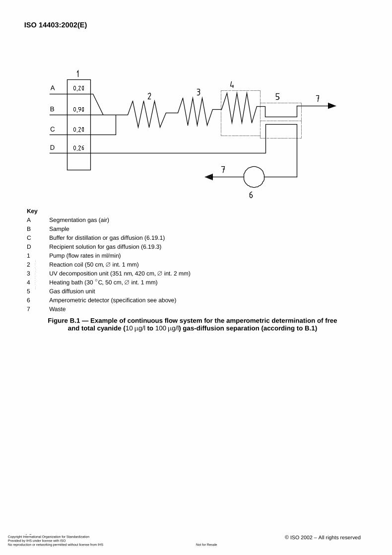
Key
A Segmentation gas (air)
B Sample
C Buffer for distillation or gas diffusion (6.19.1)
D Recipient solution for gas diffusion (6.19.3)
1 Pump (flow rates in )
2 Reaction coil ( , ∅ int. )
3 UV decomposition unit ( , , ∅ int. )
4 Heating bath ( , , ∅ int. )
5 Gas diffusion unit
6 Amperometric detector (specification see above)
7 Waste
Figure B.1 — Example of continuous flow system for the amperometric determination of free and total cyanide ( to ) gas-diffusion separation (according to B.1)
ml/min
50 cm 1 mm
351 nm 420 cm 2 mm
30 ◦C 50 cm 1 mm
10 µg/l 100 µg/l
Copyright International Organization for Standardization Provided by IHS under license with ISO
Not for ResaleNo reproduction or networking permitted without license from IHS
--`,,`,-`-`,,`,,`,`,,`---
ISO 14403:2002(E)
© ISO 2002 – All rights reserved 17
Annex C(informative)
Results of the interlaboratory trial for cyanide determination
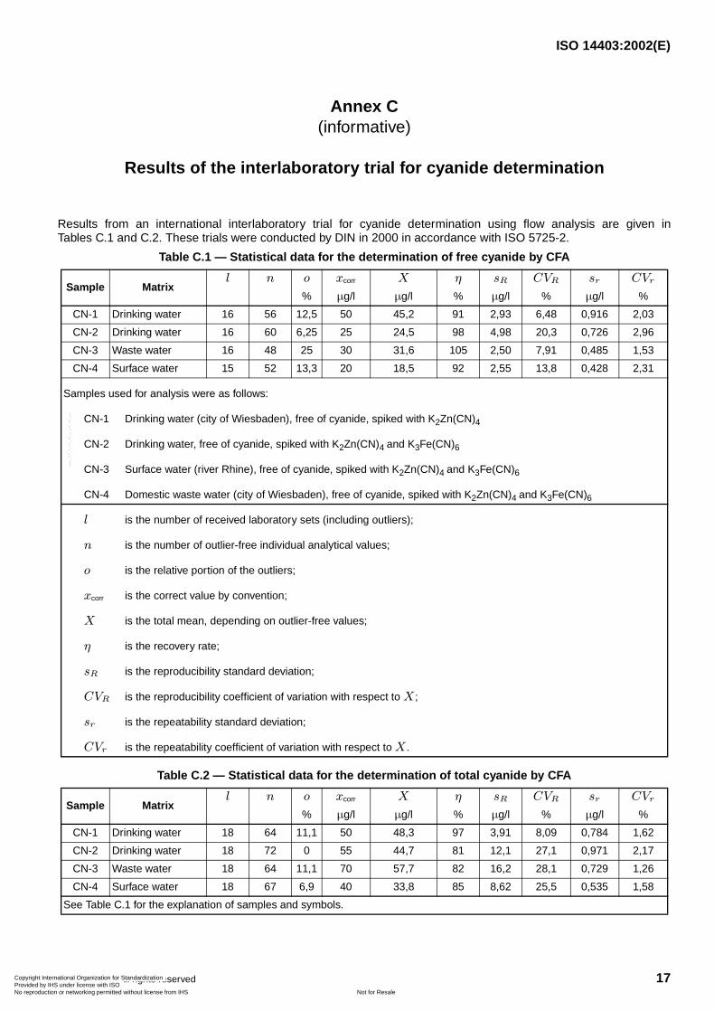
Results from an international interlaboratory trial for cyanide determination using flow analysis are given inTables C.1 and C.2. These trials were conducted by DIN in 2000 in accordance with ISO 5725-2.
Table C.1 — Statistical data for the determination of free cyanide by CFA
Sample Matrix
CN-1 Drinking water 16 56 12,5 50 45,2 91 2,93 6,48 0,916 2,03
CN-2 Drinking water 16 60 6,25 25 24,5 98 4,98 20,3 0,726 2,96
CN-3 Waste water 16 48 25 30 31,6 105 2,50 7,91 0,485 1,53
CN-4 Surface water 15 52 13,3 20 18,5 92 2,55 13,8 0,428 2,31
Samples used for analysis were as follows:
CN-1 Drinking water (city of Wiesbaden), free of cyanide, spiked with K2Zn(CN)4
CN-2 Drinking water, free of cyanide, spiked with K2Zn(CN)4 and K3Fe(CN)6
CN-3 Surface water (river Rhine), free of cyanide, spiked with K2Zn(CN)4 and K3Fe(CN)6
CN-4 Domestic waste water (city of Wiesbaden), free of cyanide, spiked with K2Zn(CN)4 and K3Fe(CN)6
is the number of received laboratory sets (including outliers);
is the number of outlier-free individual analytical values;
is the relative portion of the outliers;
is the correct value by convention;
is the total mean, depending on outlier-free values;
is the recovery rate;
is the reproducibility standard deviation;
is the reproducibility coefficient of variation with respect to ;
is the repeatability standard deviation;
is the repeatability coefficient of variation with respect to .
Table C.2 — Statistical data for the determination of total cyanide by CFA
Sample Matrix
CN-1 Drinking water 18 64 11,1 50 48,3 97 3,91 8,09 0,784 1,62
CN-2 Drinking water 18 72 0 55 44,7 81 12,1 27,1 0,971 2,17
CN-3 Waste water 18 64 11,1 70 57,7 82 16,2 28,1 0,729 1,26
CN-4 Surface water 18 67 6,9 40 33,8 85 8,62 25,5 0,535 1,58
See Table C.1 for the explanation of samples and symbols.
l n o xcorr X η sR CVR sr CVr
% µg/l µg/l % µg/l % µg/l %
l
n
o
xcorr
X
η
sR
CVR X
sr
CVr X
l n o xcorr X η sR CVR sr CVr
% µg/l µg/l % µg/l % µg/l %
Copyright International Organization for Standardization Provided by IHS under license with ISO
Not for ResaleNo reproduction or networking permitted without license from IHS
--`,,`,-`-`,,`,,`,`,,`---
ISO 14403:2002(E)
18 © ISO 2002 – All rights reserved
Bibliography
[1] EPA-600/4-79-020, Methods for Chemical Analysis of Water and Wastes, STORET NO. 00720, EPA Cincinnati,OH 1979; EPA 336.3 “Cyanide, Total (Colorimetric, Automated UV)”, 1978
[2] NEN 6655, Water and soil — Photometric determination of the content of total and free cyanide by continuousflow analysis1)
[3] KELADA, N.P., Automated direct measurements of total cyanide species and thiocyanates, and their distributionin waste water and sludge. Journal WPCF, 61 (3), 1989, pp. 350-356
[4] MEEUSSEN, J.C.L., TEMMINGHOF, E.J.M., KEIZER, M.G. and NOVOZAMSKY, I. Spectrophotometric determinationof total cyanide, iron-cyanide complexes and thiocyanate in water by a continuous flow system. Analyst, 114(118), 1989, pp. 959-963
[5] TAUW Infra Consult BV. Laboratory study on cyanide determination. Project No. 3162052, Deventer, May 1992
[6] BERMAN, R., CHRISTMANN, D. and RENN, C. Automated determination of weak acid dissociable and totalcyanide without thiocyanate interference. American Environmental Laboratory, 5, 1993, pp. 32-34
[7] SEKERKA, I. and LECHNER, J.F. Determination of cyanide by continuous flow iso-thermal distillation withamperometric detection. National Water Research Institute of Canada, NWRI Report, pp. 91-108
[8] PIHLAR, B., KOSTA, L. and HRISTOVSKI, B. Amperometric Determination of cyanide by use of a flow-throughelectrode. Talanta, Pergamon Press Ltd., 26, 1979, pp. 805-810
[9] NAGY, A. and NAGY, G., Amperometric air gap cell for the measurement of free cyanide. Analytica ChimicaActa, Elsevier Science Publishers BV, Amsterdam, 283, 1993, pp. 795-802
[10] NIKOLIC, S., MILOSAVLJEVIC, E., HENDRIX, J. and NELSON, J. Flow injection amperometric determination ofcyanide on a modified silver electrode. Analyst, January 1992, p. 117
1) This Dutch national standard is also suitable for the determination of free and total cyanide in soil and sludge.
Copyright International Organization for Standardization Provided by IHS under license with ISO
Not for ResaleNo reproduction or networking permitted without license from IHS
--`,,`,-`-`,,`,,`,`,,`---

Copyright International Organization for Standardization Provided by IHS under license with ISO
Not for ResaleNo reproduction or networking permitted without license from IHS
--`,,`,-`-`,,`,,`,`,,`---
ISO 14403:2002(E)
ICS 13.060.50Price based on 18 pages
© ISO 2002 – All rights reserved
Copyright International Organization for Standardization Provided by IHS under license with ISO
Not for ResaleNo reproduction or networking permitted without license from IHS
--`,,`,-`-`,,`,,`,`,,`---