Embed Size (px)
Citation preview

Reference numberNuméro de référence
ISO 1219-1:2012(E/F)
© ISO 2012
INTERNATIONAL STANDARD
NORME INTERNATIONALE
ISO1219-1
Third editionTroisième édition
2012-06-01
Fluid power systems and components — Graphical symbols and circuit diagrams —
Part 1: Graphical symbols for conventional use and data-processing applications
Transmissions hydrauliques et pneumatiques — Symboles graphiques et schémas de circuit —
Partie 1: Symboles graphiques en emploi conventionnel et informatisé
Licensed to: Rockhill, Denise MsDownloaded: 2017-04-17Single user licence only, copying and networking prohibited

ISO 1219-1:2012(E/F)
COPYRIGHT PROTECTED DOCUMENT DOCUMENT PROTÉGÉ PAR COPYRIGHT
© ISO 2012
All rights reserved. Unless otherwise specified, no part of this publication may be reproduced or utilized in any form or by any means, electronic or mechanical, including photocopying and microfilm, without permission in writing from either ISO at the address below or ISO's member body in the country of the requester. / Droits de reproduction réservés. Sauf prescription différente, aucune partie de cette publication ne peut être reproduite ni utilisée sous quelque forme que ce soit et par aucun procédé, électronique ou mécanique, y compris la photocopie et les microfilms, sans l'accord écrit de l’ISO à l’adresse ci-après ou du comité membre de l’ISO dans le pays du demandeur.
ISO copyright office Case postale 56 CH-1211 Geneva 20 Tel. + 41 22 749 01 11 Fax + 41 22 749 09 47 E-mail [email protected] Web www.iso.org
Published in Switzerland/Publié en Suisse
ii © ISO 2012 – All rights reserved/Tous droits réservés
Licensed to: Rockhill, Denise MsDownloaded: 2017-04-17Single user licence only, copying and networking prohibited

ISO 1219-1:2012(E/F)
© ISO 2012 – All rights reserved/Tous droits réservés iii
Contents Page
Foreword ........................................................................................................................................................... vii
Introduction ........................................................................................................................................................ ix
1 Scope ...................................................................................................................................................... 1
2 Normative references ............................................................................................................................ 2
3 Terms and definitions ........................................................................................................................... 3
4 Identification statement (Reference to this part of ISO 1219) .............................................................. 3
5 General rules .......................................................................................................................................... 3
6 Examples of hydraulic applications .................................................................................................... 8 6.1 Valves ..................................................................................................................................................... 8 6.1.1 Control mechanisms ............................................................................................................................. 8 6.1.2 Directional control valves ................................................................................................................... 11 6.1.3 Pressure control valves ...................................................................................................................... 17 6.1.4 Flow-control valves ............................................................................................................................. 21 6.1.5 Non-return (check) valves and shuttle valves .................................................................................. 23 6.1.6 Proportional directional control valves ............................................................................................. 25 6.1.7 Proportional pressure control valves ................................................................................................ 29 6.1.8 Proportional flow control valves ........................................................................................................ 32 6.1.9 Two-port slip-in cartridge valves ....................................................................................................... 34 6.2 Pumps and motors .............................................................................................................................. 47 6.3 Cylinders .............................................................................................................................................. 54 6.4 Accessories ......................................................................................................................................... 57 6.4.1 Connections and joints ....................................................................................................................... 57 6.4.2 Electrical equipment ........................................................................................................................... 59 6.4.3 Measuring instruments and indicators ............................................................................................. 60 6.4.4 Filters and separators ......................................................................................................................... 64 6.4.5 Heat exchangers .................................................................................................................................. 68 6.4.6 Energy accumulators (pressure vessels, gas bottles) .................................................................... 69 6.4.7 Lubrication points ............................................................................................................................... 70
7 Examples of pneumatic applications ................................................................................................ 71 7.1 Valves ................................................................................................................................................... 71 7.1.1 Control mechanisms ........................................................................................................................... 71 7.1.2 Directional control valves ................................................................................................................... 75 7.1.3 Pressure control valves ...................................................................................................................... 84 7.1.4 Flow control valves ............................................................................................................................. 86 7.1.5 Non-return (check) valves and shuttle valves .................................................................................. 87 7.1.6 Proportional directional control valves ............................................................................................. 89 7.1.7 Proportional pressure control valves ................................................................................................ 90 7.1.8 Proportional flow control valves ........................................................................................................ 92 7.2 Air compressors and motors ............................................................................................................. 93 7.3 Cylinders .............................................................................................................................................. 94 7.4 Accessories ......................................................................................................................................... 99 7.4.1 Connections and joints ....................................................................................................................... 99 7.4.2 Electrical equipment ......................................................................................................................... 101 7.4.3 Measuring instruments and indicators ........................................................................................... 102 7.4.4 Filters and separators ....................................................................................................................... 103 7.4.5 Energy accumulators (pressure vessels, gas bottles) .................................................................. 110 7.4.6 Vacuum generators ........................................................................................................................... 111 7.4.7 Suction cups ...................................................................................................................................... 112
Licensed to: Rockhill, Denise MsDownloaded: 2017-04-17Single user licence only, copying and networking prohibited

ISO 1219-1:2012(E/F)
iv © ISO 2012 – All rights reserved/Tous droits réservés
8 Symbols of basic nature .................................................................................................................. 113 8.1 Lines ................................................................................................................................................... 113 8.2 Connections and joints .................................................................................................................... 114 8.3 Flow paths and direction indicators ............................................................................................... 116 8.4 Basic mechanical elements ............................................................................................................. 119 8.5 Control mechanisms elements ........................................................................................................ 129 8.6 Adjusting elements ........................................................................................................................... 133 8.7 Accessories ....................................................................................................................................... 135
9 Application rules ............................................................................................................................... 142 9.1 General symbols ............................................................................................................................... 142 9.2 Valves ................................................................................................................................................. 143 9.3 Two-port slip-in cartridge valves .................................................................................................... 152 9.4 Pumps and motors ........................................................................................................................... 155 9.5 Cylinders ............................................................................................................................................ 158 9.6 Accessories ....................................................................................................................................... 160 9.6.1 Connections and joints .................................................................................................................... 160 9.6.2 Electrical equipment ......................................................................................................................... 162 9.6.3 Measuring instruments and indicators .......................................................................................... 163 9.6.4 Sources of energy............................................................................................................................. 164
Annex A (informative) Recommendations for the creation of CAD symbols ........................................... 165
Bibliography ................................................................................................................................................... 178
Licensed to: Rockhill, Denise MsDownloaded: 2017-04-17Single user licence only, copying and networking prohibited

ISO 1219-1:2012(E/F)
© ISO 2012 – All rights reserved/Tous droits réservés v
Sommaire
Avant-propos ................................................................................................................................................... viii
Introduction ......................................................................................................................................................... x
1 Domaine d'application .......................................................................................................................... 1
2 Références normatives ......................................................................................................................... 2
3 Termes et définitions ............................................................................................................................ 3
4 Phrase d'identification (Référence à la présente partie de l'ISO 1219) ............................................... 3
5 Règles générales ................................................................................................................................... 3
6 Exemples d'applications hydrauliques ............................................................................................... 8 6.1 Distributeurs .......................................................................................................................................... 8 6.1.1 Mécanismes de commande .................................................................................................................. 8 6.1.2 Distributeurs de commande directionnels ....................................................................................... 11 6.1.3 Distributeurs de commande de pression .......................................................................................... 17 6.1.4 Distributeurs de commande de débit ................................................................................................ 21 6.1.5 Clapets antiretour et sélecteurs de circuit ........................................................................................ 23 6.1.6 Distributeurs proportionnels de commande directe ....................................................................... 25 6.1.7 Distributeurs proportionnels de commande de pression ............................................................... 29 6.1.8 Distributeurs proportionnels de commande de débit ..................................................................... 32 6.1.9 Distributeurs à cartouche à bride à deux orifices ............................................................................ 34 6.2 Pompes et moteurs ............................................................................................................................. 47 6.3 Vérins .................................................................................................................................................... 54 6.4 Accessoires ......................................................................................................................................... 57 6.4.1 Connexions et raccordements ........................................................................................................... 57 6.4.2 Équipement électrique ........................................................................................................................ 59 6.4.3 Appareils de mesure et indicateurs ................................................................................................... 60 6.4.4 Filtres et séparateurs .......................................................................................................................... 64 6.4.5 Échangeurs de chaleur ....................................................................................................................... 68 6.4.6 Accumulateurs d'énergie (réservoirs sous pression, bouteilles à gaz) ........................................ 69 6.4.7 Points de lubrification ......................................................................................................................... 70
7 Exemples d'applications pneumatiques ........................................................................................... 71 7.1 Distributeurs ........................................................................................................................................ 71 7.1.1 Mécanismes de commande ................................................................................................................ 71 7.1.2 Distributeurs de commande directionnels ....................................................................................... 75 7.1.3 Distributeurs de commande de pression .......................................................................................... 84 7.1.4 Distributeurs de commande de débit ................................................................................................ 86 7.1.5 Clapets antiretour et sélecteurs de circuit........................................................................................ 87 7.1.6 Distributeurs proportionnels de commande directe ....................................................................... 89 7.1.7 Distributeurs proportionnels de commande de pression ............................................................... 90 7.1.8 Distributeurs proportionnels de commande de débit ..................................................................... 92 7.2 Compresseurs et moteurs .................................................................................................................. 93 7.3 Vérins .................................................................................................................................................... 94 7.4 Accessoires ......................................................................................................................................... 99 7.4.1 Connexions et raccordements ........................................................................................................... 99 7.4.2 Équipement électrique ...................................................................................................................... 101 7.4.3 Appareils de mesure et indicateurs ................................................................................................. 102 7.4.4 Filtres et séparateurs ........................................................................................................................ 103 7.4.5 Accumulateurs d'énergie (réservoirs sous pression, bouteilles à gaz) ...................................... 110 7.4.6 Générateurs de vide .......................................................................................................................... 111 7.4.7 Ventouses .......................................................................................................................................... 112
Licensed to: Rockhill, Denise MsDownloaded: 2017-04-17Single user licence only, copying and networking prohibited

ISO 1219-1:2012(E/F)
vi © ISO 2012 – All rights reserved/Tous droits réservés
8 Symboles de base............................................................................................................................. 113 8.1 Traits .................................................................................................................................................. 113 8.2 Connexions et raccordements ........................................................................................................ 114 8.3 Voies d'écoulement et indicateurs de sens ................................................................................... 116 8.4 Éléments de base mécaniques ........................................................................................................ 119 8.5 Éléments de mécanismes de commande ....................................................................................... 129 8.6 Éléments de réglage ......................................................................................................................... 133 8.7 Accessoires ....................................................................................................................................... 135
9 Règles d'application ......................................................................................................................... 142 9.1 Symboles généraux .......................................................................................................................... 142 9.2 Distributeurs ...................................................................................................................................... 143 9.3 Distributeurs à cartouche à bride à deux orifices ......................................................................... 152 9.4 Pompes et moteurs........................................................................................................................... 155 9.5 Vérins ................................................................................................................................................. 158 9.6 Accessoires ....................................................................................................................................... 160 9.6.1 Connexions et raccordements ........................................................................................................ 160 9.6.2 Équipement électrique ..................................................................................................................... 162 9.6.3 Appareils de mesurage et indicateurs ............................................................................................ 163 9.6.4 Sources d'énergie ............................................................................................................................. 164
Annexe A (informative) Recommandations pour la création des symboles de CAO ............................. 165
Bibliographie .................................................................................................................................................. 178
Licensed to: Rockhill, Denise MsDownloaded: 2017-04-17Single user licence only, copying and networking prohibited

ISO 1219-1:2012(E/F)
© ISO 2012 – All rights reserved/Tous droits réservés vii
Foreword
ISO (the International Organization for Standardization) is a worldwide federation of national standards bodies (ISO member bodies). The work of preparing International Standards is normally carried out through ISO technical committees. Each member body interested in a subject for which a technical committee has been established has the right to be represented on that committee. International organizations, governmental and non-governmental, in liaison with ISO, also take part in the work. ISO collaborates closely with the International Electrotechnical Commission (IEC) on all matters of electrotechnical standardization.
International Standards are drafted in accordance with the rules given in the ISO/IEC Directives, Part 2.
The main task of technical committees is to prepare International Standards. Draft International Standards adopted by the technical committees are circulated to the member bodies for voting. Publication as an International Standard requires approval by at least 75 % of the member bodies casting a vote.
Attention is drawn to the possibility that some of the elements of this document may be the subject of patent rights. ISO shall not be held responsible for identifying any or all such patent rights.
ISO 1219-1 was prepared by Technical Committee ISO/TC 131, Fluid power systems.
This third edition cancels and replaces the second edition (ISO 1219-1:2006), which has been technically revised.
ISO 1219 consists of the following parts, under the general title Fluid power systems and components — Graphical symbols and circuit diagrams:
Part 1: Graphical symbols for conventional use and data-processing applications
Part 2: Circuit diagrams
Licensed to: Rockhill, Denise MsDownloaded: 2017-04-17Single user licence only, copying and networking prohibited
ISO 1219-1:2012(E/F)
viii © ISO 2012 – All rights reserved/Tous droits réservés
Avant-propos
L'ISO (Organisation internationale de normalisation) est une fédération mondiale d'organismes nationaux de normalisation (comités membres de l'ISO). L'élaboration des Normes internationales est en général confiée aux comités techniques de l'ISO. Chaque comité membre intéressé par une étude a le droit de faire partie du comité technique créé à cet effet. Les organisations internationales, gouvernementales et non gouvernementales, en liaison avec l'ISO participent également aux travaux. L'ISO collabore étroitement avec la Commission électrotechnique internationale (CEI) en ce qui concerne la normalisation électrotechnique.
Les Normes internationales sont rédigées conformément aux règles données dans les Directives ISO/CEI, Partie 2.
La tâche principale des comités techniques est d'élaborer les Normes internationales. Les projets de Normes internationales adoptés par les comités techniques sont soumis aux comités membres pour vote. Leur publication comme Normes internationales requiert l'approbation de 75 % au moins des comités membres votants.
L'attention est appelée sur le fait que certains des éléments du présent document peuvent faire l'objet de droits de propriété intellectuelle ou de droits analogues. L'ISO ne saurait être tenue pour responsable de ne pas avoir identifié de tels droits de propriété et averti de leur existence.
L'ISO 1219-1 a été élaborée par le comité technique ISO/TC 131, Transmissions hydrauliques et pneumatiques.
Cette troisième édition annule et remplace la deuxième édition (ISO 1219-1:2006), dont elle constitue une révision mineure.
L'ISO 1219 comprend les parties suivantes, présentées sous le titre général Transmissions hydrauliques et pneumatiques — Symboles graphiques et schémas de circuit:
Partie 1: Symboles graphiques en emploi conventionnel et informatisé
Partie 2: Schémas de circuit
Licensed to: Rockhill, Denise MsDownloaded: 2017-04-17Single user licence only, copying and networking prohibited

ISO 1219-1:2012(E/F)
© ISO 2012 – All rights reserved/Tous droits réservés ix
Introduction
In fluid power systems, power is transmitted and controlled through a fluid (liquid or gas) under pressure within a circuit.
Graphical symbols are intended to describe fluid power components and their function. They are used in circuit diagrams, on nameplates, in catalogues and in other commercial literature.
Licensed to: Rockhill, Denise MsDownloaded: 2017-04-17Single user licence only, copying and networking prohibited

ISO 1219-1:2012(E/F)
x © ISO 2012 – All rights reserved/Tous droits réservés
Introduction
Dans les systèmes de transmissions hydrauliques et pneumatiques, l'énergie est transmise et commandée par l'intermédiaire d'un fluide (liquide ou gaz) sous pression circulant dans un circuit.
Les symboles graphiques servent à représenter les composants pour transmissions hydrauliques et pneumatiques ainsi que leur fonction. Ils figurent sur les schémas de circuit, les plaques signalétiques, les catalogues et les descriptions de produits.
Licensed to: Rockhill, Denise MsDownloaded: 2017-04-17Single user licence only, copying and networking prohibited

FINAL DRAFT INTERNATIONAL STANDARD PROJET FINAL DE NORME INTERNATIONALE
ISO/FDIS 1219-1:2012(E/F)
© ISO 2012 – All rights reserved/Tous droits réservés 1
Fluid power systems and components — Graphical symbols and circuit diagrams —
Part 1: Graphical symbols for conventional use and data-processing applications
Transmissions hydrauliques et pneumatiques — Symboles graphiques et schémas de circuit —
Partie 1: Symboles graphiques en emploi conventionnel et informatisé
1 Scope
1 Domaine d'application
This part of ISO 1219 establishes basic elements for symbols. It specifies rules for devising fluid power symbols for use on components and in circuit diagrams.
This part of ISO 1219 is a collective application standard of the ISO 14617 series. In this part of ISO 1219, the symbols are designed in fixed dimensions to be used directly in data processing systems, which might result in different variants.
La présente partie de l'ISO 1219 définit des éléments de base pour symboles. Elle établit des règles de formation de symboles des transmissions hydrauliques et pneumatiques à utiliser sur les composants et les schémas de circuit.
La présente partie de l'ISO 1219 est une application collective de la série ISO 14617. Dans la présente partie de l'ISO 1219, les symboles sont dessinés avec des dimensions fixes pour être directement utilisés dans les systèmes de traitement de données, qui peuvent avoir comme conséquences différentes variantes.
NOTE In addition to terms in English and French, two of the three official ISO languages, this part of ISO 1219 gives the equivalent terms in German; these are published under the responsibility of the member body for Germany (DIN). However, only the terms and definitions given in the official languages can be considered as ISO terms and definitions.
NOTE En complément des termes en anglais et en français, deux des trois langues officielles de l'ISO, la présente partie de l'ISO 1219 donne les termes équivalents en allemand; ces termes sont publiés sous la responsabilité du comité membre allemand (DIN). Toutefois, seuls les termes et définitions donnés dans les langues officielles peuvent être considérés comme étant des termes et définitions de l'ISO.
Licensed to: Rockhill, Denise MsDownloaded: 2017-04-17Single user licence only, copying and networking prohibited

ISO 1219-1:2012(E/F)
2 © ISO 2012 – All rights reserved/Tous droits réservés
2 Normative references
The following referenced documents are indispensable for the application of this document. For dated references, only the edition cited applies. For undated references, the latest edition of the referenced document (including any amendments) applies.
ISO 128 (all parts), Technical drawings — General principles of presentation
ISO 3098-5, Technical product documentation —Lettering — Part 5: CAD lettering of the Latin alphabet, numerals and marks
ISO 5598, Fluid power systems and components —Vocabulary
ISO 14617 (all parts), Graphical symbols for diagrams
ISO 81714-1, Design of graphical symbols for use in technical documentation of products — Part 1: Basic rules
IEC 81714-2, Design of graphical symbols for use in the technical documentation of products — Part 2: Specification for graphical symbols in a computer sensible form including graphical symbols for a reference library, and requirements for their interchange
2 Références normatives
Les documents de référence suivants sont indispensables pour l'application du présent document. Pour les références datées, seule l'édition citée s'applique. Pour les références non datées, la dernière édition du document de référence s'applique (y compris les éventuels amendements).
ISO 128 (toutes les parties), Dessins techniques —Principes généraux de représentation
ISO 3098-5, Documentation technique de produits —Écriture — Partie 5: Écriture en conception assistée par ordinateur de l'alphabet latin, des chiffres et des signes
ISO 5598, Transmissions hydrauliques et pneumatiques — Vocabulaire
ISO 14617 (toutes les parties), Symboles graphiques pour schémas
ISO 81714-1, Création de symboles graphiques à utiliser dans la documentation technique de produits — Partie 1: Règles fondamentales
CEI 81714-2, Création de symboles graphiques utilisables dans la documentation technique de produits — Partie 2: Spécification pour symboles graphiques sous forme adaptée à l'ordinateur, y compris les symboles pour bibliothèque de références, et exigences relatives à leur échange
Licensed to: Rockhill, Denise MsDownloaded: 2017-04-17Single user licence only, copying and networking prohibited

ISO 1219-1:2012(E/F)
© ISO 2012 – All rights reserved/Tous droits réservés 3
3 Terms and definitions 3 Termes et définitions 3 Begriffe und Definitionen
For the purposes of thisdocument, the terms and defini-tions given in ISO 5598 apply.
Pour les besoins du présentdocument, les termes et défini-tions donnés dans l'ISO 5598 s'appliquent.
Für die Anwendung diesesDokuments gelten die Begriffenach ISO 5598.
4 Identification statement (Reference to this part of ISO 1219)
4 Phrase d'identification (Référence à la présente partie de l'ISO 1219)
4 Kennzeichnungs-vermerk
Use the following statement in testreports, catalogues and salesliterature when claimingcompliance with this part ofISO 1219:
“Graphical symbols are inaccordance with ISO 1219-1:2012,Fluid power systems andcomponents — Graphical symbols and circuit diagrams — Part 1: Graphical symbols for conventionaluse and data-processing applications.”
Pour signaler la conformité à laprésente partie de l'ISO 1219, la phrase d'identification à utiliserdans les rapports d'essai,catalogues et documentation commerciale est la suivante:
«Les symboles graphiques sontconformes à l'ISO 1219-1:2012, Transmissions hydrauliques etpneumatiques — Symboles gra-phiques et schémas de circuit —Partie 1: Symboles graphiques en emploi conventionnel etinformatisé.»
Als Hinweis auf die Einhaltungdieses Teils der ISO 1219 ist derfolgende Text in Prüfberichten,Katalogen und Verkaufsunter-lagen zu verwenden:
„Die graphischen Symboleentsprechen ISO 1219-1:2012,Fluidtechnik — GraphischeSymbole und Schaltpläne — Teil 1:Graphische Symbole für konven-tionelle und datentechnischeAnwendungen.”
5 General rules
5 Règles générales
5 Allgemeine Regeln
5.1 Symbols for componentsare created using the symbols ofbasic nature specified in this partof ISO 1219 and taking intoaccount the rules given for theircreation.
5.1 Les symboles pour les composants sont à créer enutilisant les symboles de base spécifiés dans la présente partiede l'ISO 1219 et en tenant compte des règles données pour lacréation.
5.1 Symbole für Bauteile sindaus in diesem Teil von ISO 1219festgelegten Grundsymbolenunter Berücksichtigung dervorgegebenen Bildungsregeln zuerstellen.
5.2 Most symbols representcomponents and devices withspecified functions. Some sym-bols represent instead functions ormethods of operation.
5.2 La plupart des symboles représente des composants et des appareils aux fonctions défi-nies. Toutefois, certains symbolesreprésentent également des fonc-tions ou procédés de commande.
5.2 Die meisten Symbole stel-len Bauteile und Geräte mit fest-gelegten Funktionen dar. MancheSymbole stellen aber auch Funk-tionen oder Betätigungsverfahrendar.
5.3 Symbols are not intended toshow the actual construction of acomponent.
5.3 Les symboles ne visent pasà une représentation réelle d'uncomposant.
5.3 Symbole dienen nicht demZweck, die Konstruktion einesGerätes darzustellen.
Licensed to: Rockhill, Denise MsDownloaded: 2017-04-17Single user licence only, copying and networking prohibited

ISO 1219-1:2012(E/F)
4 © ISO 2012 – All rights reserved/Tous droits réservés
5.4 Symbols of componentsshow the de-energized (at-rest)position of a component. Symbolsof components that do not have aclearly defined de-energized (at-rest) position shall be createdaccording to the component-specific rules for the creation ofsymbols established in this part ofISO 1219.
NOTE The rules applicable tocircuit diagrams are given inISO 1219-2.
5.4 Les symboles descomposants présentent lescomposants en position repos.Les symboles des composants qui n'ont pas une position reposclairement définie doivent êtrecréés suivant les règles decréation de symboles spécifiquesà ces composants établies dansla présente partie de l'ISO 1219.
NOTE Les règles applicables aux schémas de circuits sont données dans l'ISO 1219-2.
5.4 Symbole zeigen die Ruhestellung eines Bauteils. Symbole für Bauteile, die keine eindeutige Ruhestellung haben, werden nach den in diesem Teil von ISO 1219 fixierten, bauteilspezifischen Bildungsregeln angelegt.
ANMERKUNG Die Regeln zur Erstellung von Schaltplänen sind in ISO 1219-2 enthalten.
5.5 Symbols of componentsshall show all the connectionsprovided.
5.5 Les symboles descomposants doivent présentertoutes les connexions prévues.
5.5 Symbole für Bauteile müssen alle vorhandenen An-schlüsse aufweisen.
5.6 Symbols shall have all therequired free spaces for indicatingthe port/connection designationsand parameters such as pressure,flow, electrical connection, etc., orcomponent settings.
5.6 Les symboles doiventcomporter toutes les cases libresnécessaires pour indiquer la dési-gnation de l'orifice/raccordementet de variables telles que lapression, le débit, leraccordement électrique, etc. ou les réglages des appareils.
5.6 Symbole müssen alle erfor-derlichen Platzhalter zur Angabe der Anschlussbezeichnung und der Angaben über Größen wie Druck, Volumenstrom, Elektroan-schluss usw. oder Geräteeinstel-lungen haben.
5.7 In accordance withISO 81714-1, symbols of basicnature may be mirrored or turnedwhen graphical symbols are beingcreated unless doing sotransforms them into an existingsymbol of basic nature.
5.7 Conformément à l'ISO 81714-1, les éléments de base peuvent être tournés ouinversés pour la création desymboles graphiques, tant qu’ils ne sont pas transformés en unélément de base existant.
5.7 Nach ISO 81714-1 dürfen Grundsymbole zur Bildung von graphischen Symbolen gedreht oder gespiegelt werden, solange sie nicht zu einem existierenden Grundsymbol werden.
5.8 The symbols are shown inthe original position as defined inthis part of ISO 1219 and inISO 81714-1. They may bemirrored or rotated in 90°increments without changing theirmeaning.
5.8 Les symboles sontprésentés dans la positionoriginelle, comme défini dans la présente partie de l'ISO 1219 et dans l'ISO 81714-1. Les symboles peuvent être inversés ou tournéspar pas de 90° sans incidence surleur signification.
5.8 Die Symbole sind in der Originallage, wie in diesem Teil von ISO 1219 und in ISO 81714-1 definiert, dargestellt. Sie dürfen ohne Einfluss auf ihre Bedeutung gespiegelt oder in Schritten von 90° gedreht werden.
Licensed to: Rockhill, Denise MsDownloaded: 2017-04-17Single user licence only, copying and networking prohibited

ISO 1219-1:2012(E/F)
© ISO 2012 – All rights reserved/Tous droits réservés 5
5.9 If a symbol represents afluid power component with two ormore main functions that areconnected to each other, thesymbol shall be enclosed by asolid line (see 8.1.1).
NOTE 1 For example, the duty ofcontrol mechanisms on directionalcontrol valves and indication ofclogging of a filter are not consideredmain functions.
NOTE 2 This is a change fromISO 1219-1:1991, in which the linewas dash-dotted. The reason for thechange is to improve clarity.
5.9 Lorsqu'un symbole detransmissions hydrauliques e
t
pneumatiques représente uncomposant doté de plusieursfonctions principales intercon-nectées, le symbole doit être entouré par un cadre en trait plein(voir 8.1.1).
NOTE 1 La commande des distributeurs ou l'indication du colmatage des filtres ne sont pas àconsidérer comme fonctionsprincipales.
NOTE 2 Ce point constitue un amendement par rapport àl'ISO 1219-1:1991, dans laquelle ce trait était mixte. La raison de cechangement est d'améliorer la clarté.
5.9 Wenn ein Symbol einfluidtechnisches Bauteil mitmehreren Hauptfunktionen, dieuntereinander verbunden sind,darstellt, ist das Symbol mit einerdurchgezogenen Linie zuumrahmen (siehe 8.1.1).
ANMERKUNG 1 Die Betätigungvon Wegeventilen und das Anzeigender Verschmutzung bei Filtern sindzum Beispiel nicht als Hauptfunktio-nen anzusehen.
ANMERKUNG 2 Das ist eineÄnderung gegenüber der vorange-gangenen Ausgabe von ISO 1219-1:1991, bei der diese Linie strich-punktiert dargestellt wurde. DieseÄnderung wurde vorgenommen, umdie Darstellung zu verdeutlichen.
5.10 Where two or morecomponents are contained in oneassembly, their symbols shall beenclosed by a dash-dotted narrow line (see 7.4.4.17).
5.10 Lorsqu'une unité réunit deux ou plusieurs composants,leurs symboles doivent être entourés par un cadre en trait mixte fin (voir 7.4.4.17).
5.10 Wenn zwei oder mehrBauteile in einer Einheit enthaltensind, müssen sie mit einerstrichpunktierten Linie eingerahmtwerden (siehe 7.4.4.17).
5.11 The dotted line used in thispart of ISO 1219 is employed forrepresenting adjacent basicelements or components. It is notused in graphical symbols.
5.11 Le trait en pointillés utilisé dans la présente partie del'ISO 1219 sert à représenter les éléments de base ou composantsadjacents. Il n'est pas utilisé dansles symboles graphiques.
5.11 Die in diesem Teil vonISO 1219 verwendete gepunkteteLinie wird zur Darstellungangrenzender Grundelementeoder Bauteile genutzt. Sie wirdnicht in Symbolen verwendet.
Licensed to: Rockhill, Denise MsDownloaded: 2017-04-17Single user licence only, copying and networking prohibited

ISO 1219-1:2012(E/F)
6 © ISO 2012 – All rights reserved/Tous droits réservés
5.12 The graphical symbols inthis part of ISO 1219 are drawn inaccordance with ISO 14617 (allparts) and the rules inISO 81714-1 and IEC 81714-2.Graphical symbols in accordancewith ISO 14617 (all parts) aredrawn with a module sizeM = 2,5 mm and a line thicknessof 0,25 mm. To minimize symbolsize, graphical symbols in this partof ISO 1219 are drawn with amodule size M = 2,0 mm and aline thickness of 0,2 mm. For bothmodule sizes, however, letteringshall be 2,5 mm high with a linethickness of 0,25 mm. It ispossible to scale graphicalsymbols used on componentlabels or catalogues as required.
5.12 Les symboles graphiquescontenus dans la présente partie de l'ISO 1219 sont dessinés conformément à l'ISO 14617 (toutes les parties) et aux règlesde l'ISO 81714-1 et de la CEI 81714-2. Les symboles graphiques conformes à l'ISO 14617 (toutes les parties)sont dessinés avec une taille de module de M = 2,5 mm et une épaisseur de ligne de 0,25 mm. Afin de réduire la taille dessymboles, les symboles graphiques dans la présente partiede l'ISO 1219 sont dessinés avecune taille de module deM = 2,0 mm et une épaisseur deligne de 0,2 mm. Toutefois, pour les deux tailles de module la hauteur de lettres doit être de 2,5 mm et l'épaisseur de ligne de 0,25 mm. Il est possible de faireappel aux multiples requis pour lesplaques signalétiques ou lescatalogues.
5.12 Die graphischen Symbole in diesem Teil von ISO 1219 sind nach ISO 14617 (alle Teile) und nach den Regeln in ISO 81714-1 und IEC 81714-2 gezeichnet. Graphische Symbole in ISO 14617 (alle Teile) sind mit Modul M =2,5 mm und Linienbreite 0,25 mm gezeichnet. Um die Symbolgröße zu minimieren, werden die graphischen Symbole in diesem Teil von ISO 1219 miteinem Modul M = 2,0 mm und einer Linienbreite von 0,2 mm gezeichnet. Für beide Module gilt die Schriftgröße 2,5 mm mit einer Linienbreite von 0,25 mm. Für Typenschilder oder Kataloge dürfen erforderliche Skalierungen vorgenommen werden.
5.13 Dimensions of lettering andport labelling should be accordingto ISO 3098-5, character shapeCB.
5.13 Il convient que la taille deslettres et la désignation desorifices soient conformes àl'ISO 3098-5, écriture de type CB.
5.13 Die Maße der Beschriftung und Anschlussbezeichnungen sollten nach ISO 3098-5, Schriftform CB sein.
Licensed to: Rockhill, Denise MsDownloaded: 2017-04-17Single user licence only, copying and networking prohibited

ISO 1219-1:2012(E/F)
© ISO 2012 – All rights reserved/Tous droits réservés 7
5.14 Each graphical symbol inthis part of ISO 1219 is assigned aunique registration numberaccording to ISO 14617 (all parts).The variants are identified withV1, V2, V3, etc., after the registration number.
For registration numbers not yetspecified in ISO 14617 (all parts),a preliminary registration numberis used. For the field of fluid powerthe registration number isindicated by “F” for symbols ofbasic nature and by “RF” forapplication rules before thenumber.
Examples of symbols areindicated by “X”. The range fromX10000 to X39999 is reserved forthe field of fluid power technology.
5.14 Un numéro d'enregistrement unique est assigné à chaque symbole graphique de la présente partie de l'ISO 1219,conformément à l'ISO 14617 (toutes les parties). Les variantessont identifiées par V1, V2, V3, etc. après le numéro d'enregistrement.
Lorsqu'un numérod'enregistrement n'est pas encore spécifié dans l'ISO 14617 (toutes les parties), un numéro d'enregistrement provisoire est utilisé. Dans le domaine des transmissions hydrauliques etpneumatiques, les numérosd'enregistrement provisoire comportent, avant le numéro, soitun «F», pour les éléments de base, soit «RF», pour les règles d'application.
Les exemples de symboles sontindiqués par un «X», la plage des numéros compris entre X10000 et X39999 étant réservée au domaine des transmissionshydrauliques et pneumatiques.
5.14 Jedem graphischen Symbolin diesem Teil von ISO 1219 wirdeine eindeutige Registriernummernach ISO 14617 (alle Teile)zugeordnet. Varianten werden mitV1, V2, V3 usw. nach derRegistriernummer unterschieden.
Für noch nicht in ISO 14617 (alleTeile) festgelegte Registrier-nummern ist eine vorläufigeRegistriernummer angegeben, diefür die Fluidtechnik mit „F” fürGrundelemente und mit „RF” fürAnwendungsregeln beginnt.
Beispiele von Symbolen sind mit„X” gekennzeichnet. Für dieFluidtechnik ist derNummernbereich X10000 bisX39999 reserviert.
Licensed to: Rockhill, Denise MsDownloaded: 2017-04-17Single user licence only, copying and networking prohibited

ISO 1219-1:2012(E/F)
8 © ISO 2012 – All rights reserved/Tous droits réservés
6 Examples of hydraulic applications
Exemples d'applications hydrauliques
Anwendungsbeispiele Hydraulik
6.1 Valves
Distributeurs
Ventile
6.1.1 Control mechanisms
Mécanismes de commande
Betätigungseinrichtungen
Reg. No.
N° d'enreg.
Regist Nr.
Graphic
Graphique
Grafik
Description
Description
Beschreibung
6.1.1.1 X10010
402V5
655V1
686V1
F041V1
Control mechanism with detachable grip and detent
Commande par poignée amovible, avec dispositif de maintien en position
Betätigung mit abnehmbarem Griff und Raste
6.1.1.2 X10020
402V5
711V1
201V2
Plunger with adjustable stroke limiter
Poussoir à limitation de course variable
Stößel mit einstellbarer Hubbegrenzung
6.1.1.3 X10030
402V5
655V1
684V1
F041V1
Push/pull control mechanism with detent
Commande par poussoir et tirette à crantage
Betätigung durch Drücken und Ziehen mit Raste
Licensed to: Rockhill, Denise MsDownloaded: 2017-04-17Single user licence only, copying and networking prohibited

ISO 1219-1:2012(E/F)
© ISO 2012 – All rights reserved/Tous droits réservés 9
6.1.1.4 X10040
402V2
681V2
F041V1
655V1
Control mechanism with locking manual override
Dispositif de commande auxiliaire manuelle à crantage
Handhilfsbetätigungseinrichtung mit Raste
6.1.1.5 X10050
402V5
685V1
F041V1
655V1
Turning control mechanism with five detent positions
Commande en tournant à cinq positions de crantage
Betätigung durch Drehen mit fünf Raststellungen
6.1.1.6 X10060
402V5
2005V1
712V1
Roller lever for actuation in one direction of travel
Levier à galet pour commande dans un sens de déplacement
Rollenhebel für Betätigung in einer Verfahrrichtung
6.1.1.7 X10070
F019V2
211V1
402V5
F002V1
Control mechanism using an electric stepping motor
Commande par moteur pas à pas
Betätigung durch Schrittmotor
6.1.1.8 X10110
101V2
212V1
Solenoid coil with one winding, direction of actuation towards the valving element
Bobine d'électroaimant à un enroulement, agissant vers le composant
Magnetspule mit einer Wicklung, Wirkrichtung zum Verstellelement hin
6.1.1.9 X10120
101V2
212V2
Solenoid coil with one winding, direction of actuation away from the valving element
Bobine d'électroaimant à un enroulement, agissant à partir du composant
Magnetspule mit einer Wicklung, Wirkrichtung vom Verstellelement weg
Licensed to: Rockhill, Denise MsDownloaded: 2017-04-17Single user licence only, copying and networking prohibited

ISO 1219-1:2012(E/F)
10 © ISO 2012 – All rights reserved/Tous droits réservés
6.1.1.10 X10130
101V2
212V4
Electrical control mechanism with two coils, one acting towards the valving element and the other acting away from the valving element
Dispositif de commande électrique à deux enroulements, l'un agissant vers le composant, l'autre à partir du composant
Elektrische Betätigungseinrichtung mit zwei Wicklungen; eine wirkt gegen das Ventilelement und die andere wirkt vom Ventilelement weg
6.1.1.11 X10140
101V2
212V1
201V2
Solenoid coil with one winding, direction of actuation towards the valving element, continuously controlled
Bobine d'électroaimant à un enroulement, agissant vers le composant, réglable en permanence
Magnetspule mit einer Wicklung, Wirkrichtung zum Verstellelement hin, stetig verstellbar
6.1.1.12 X10150
101V2
212V2
201V2
Solenoid coil with one winding, direction of actuation away from the valving element, continuously controlled
Bobine d'électroaimant à un enroulement, agissant à partir du composant, réglable en permanence
Magnetspule mit einer Wicklung, Wirkrichtung vom Verstellelement weg, stetig verstellbar
6.1.1.13 X10160
101V2
212V4
201V2
Electrical control mechanism with two coils, acting in both directions towards and away from the valving element, continuously controlled
Bobine d'électroaimant à deux enroulements, agissant vers le composant et à partir du composant, réglable en permanence
Elektrische Betätigungseinrichtung mit zwei Wicklungen, Wirkrichtung zum Verstellelement hin und vom Verstellelement weg, stetig verstellbar
6.1.1.14 X10180
101V2
212V1
243V1
F035V1
Electrically operated hydraulic pilot stage with external pilot supply
Commande électrohydraulique de pilotage à alimentation externe de pilotage
Elektrisch betätigte hydraulische Vorsteuerung mit externer Steuerölversorgung
Licensed to: Rockhill, Denise MsDownloaded: 2017-04-17Single user licence only, copying and networking prohibited

ISO 1219-1:2012(E/F)
© ISO 2012 – All rights reserved/Tous droits réservés 11
6.1.1.15 X10190
402V1
241V1
401V1
Mechanical feedback
Rétroaction mécanique
Mechanische Rückführung
6.1.1.16 X10200
101V2
243V1
212V4
201V2
F035V1
Hydraulic control mechanism with two successive pilot stages with external pilot supply and continuously controlled solenoid with two windings, working in both directions, in one assembly
Commande hydraulique à deux étages de pilotage successifs, avec alimentation externe de pilotage et électroaimant proportionnel avec deux enroulements agissant en sens contraire dans un assemblage
Hydraulische Betätigung durch zwei aufeinanderfolgende Vorsteuerstufen mit externer Steuerölversorgung und Stetigmagnetspule mit zwei gegensinnig wirkenden Wicklungen in einer Einheit
6.1.2 Directional control valves
Distributeurs de commande directionnels
Schalt-Wegeventile
Reg. No.
N° d'enreg.
Regist Nr.
Graphic
Graphique
Grafik
Description
Description
Beschreibung
6.1.2.1 X10210
101V7
F028V1
2172V1
2002V1
402V5
682V1
401V2
2/2 (two-port, two-position) directional control valve, two ports, two shift positions for two directions of flow, a push control mechanism, spring return, normally closed
Distributeur 2/2, deux orifices, deux positions de commutation distinctes pour deux sens d'écoulement, commande par poussoir, rappel par ressort, normalement fermé
2/2-Wegeventil, zwei Anschlüsse, zwei Schaltstellungen für zwei Durchströmungsrichtungen, Betätigung durch Drücken, Federrückstellung, in Ruhestellung geschlossen
Licensed to: Rockhill, Denise MsDownloaded: 2017-04-17Single user licence only, copying and networking prohibited

ISO 1219-1:2012(E/F)
12 © ISO 2012 – All rights reserved/Tous droits réservés
6.1.2.2 X10220
101V7
F028V1
2002V1
101V2
212V1
2172V1
401V2
2/2 directional control valve, two ports, two shift positions, normally open, solenoid-actuated, spring return
Distributeur 2/2, deux orifices, deux positions de commutation, normalement ouvert, commande par électroaimant, rappel par ressort
2/2-Wegeventil, zwei Anschlüsse, zwei Schaltstellungen, in Ruhestellung offen, Magnetbetätigung, Federrückstellung
6.1.2.3 X10230
101V7
F026V1
F027V1
2002V1
101V2
212V1
401V2
4/2 directional control valve, solenoid-actuated, spring return
Distributeur 4/2 à commande par électroaimant, rappel par ressort
4/2-Wegeventil mit Magnetbetätigung, Federrückstellung
6.1.2.4 X10260
101V7
F026V1
F027V1
2172V1
402V5
682V1
F039V1
401V2
3/2 lockout valve with padlock
Distributeur 3/2 à commande verrouillable avec cadenas
3/2-Wegeventil mit abschließbarer Betätigung
6.1.2.5 X10270
101V7
F026V1
F027V1
2172V1
2002V1
712V1
2005V1
402V5
401V2
3/2 directional control valve controlled by a roller lever in one direction of travel and spring return
Distributeur 3/2, commande par levier à galet dans un sens, rappel par ressort
3/2-Wegeventil, einseitig betätigt durch Rollenhebel, Federrückstellung
Licensed to: Rockhill, Denise MsDownloaded: 2017-04-17Single user licence only, copying and networking prohibited

ISO 1219-1:2012(E/F)
© ISO 2012 – All rights reserved/Tous droits réservés 13
6.1.2.6 X10280
101V7
F026V1
F027V1
2172V1
2002V1
101V2
212V1
401V2
3/2 directional control valve, with three ports and two positions, controlled by a solenoid and spring return
Distributeur 3/2 avec trois orifices et deux positions de commutation, commande par électroaimant, rappel par ressort
3/2-Wegeventil mit drei Anschlüssen und zwei Schaltstellungen, Betätigung durch Magnet, Federrückstellung
6.1.2.7 X10290
101V7
F026V1
F027V1
2172V1
2002V1
101V2
212V1
681V2
402V2
655V1
F041V1
401V2
3/2 directional control valve with single solenoid, directly controlled, spring return, and manual override with detent
Distributeur 3/2 avec un électroaimant, commande directe, rappel par ressort, et commande auxiliaire manuelle par dispositif de maintien en position
3/2-Wegeventil mit einem Magnet, direkt betätigt, Federrückstellung und Hilfsbetätigungseinrichtung mit Raste
6.1.2.8 X10320
101V7
101V2
F026V1
F027V1
2002V1
212V1
401V2
402V2
655V1
681V2
F041V1
4/2 directional control valve with single solenoid, directly controlled, spring return, and manual override with detent
Distributeur 4/2 à commande directe par électroaimant, rappel par ressort, commande auxiliaire manuelle par dispositif de maintien en position
4/2-Wegeventil mit einem Magnet, direkt betätigt, Federrückstellung und Hilfsbetätigungseinrichtung mit Raste
Licensed to: Rockhill, Denise MsDownloaded: 2017-04-17Single user licence only, copying and networking prohibited
ISO 1219-1:2012(E/F)
14 © ISO 2012 – All rights reserved/Tous droits réservés
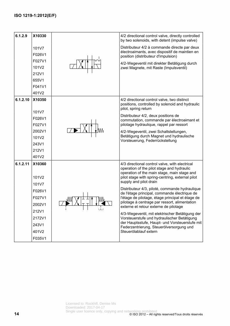
6.1.2.9 X10330
101V7
F026V1
F027V1
101V2
212V1
655V1
F041V1
401V2
4/2 directional control valve, directly controlled by two solenoids, with detent (impulse valve)
Distributeur 4/2 à commande directe par deux électroaimants, avec dispositif de maintien en position (distributeur d'impulsion)
4/2-Wegeventil mit direkter Betätigung durch zwei Magnete, mit Raste (Impulsventil)
6.1.2.10 X10350
101V7
F026V1
F027V1
2002V1
101V2
243V1
212V1
401V2
4/2 directional control valve, two distinct positions, controlled by solenoid and hydraulic pilot, spring return
Distributeur 4/2, deux positions de commutation, commande par électroaimant et pilotage hydraulique, rappel par ressort
4/2-Wegeventil, zwei Schaltstellungen, Betätigung durch Magnet und hydraulische Vorsteuerung, Federrückstellung
6.1.2.11 X10360
101V2
101V7
F026V1
F027V1
2002V1
212V1
2172V1
243V1
401V2
F035V1
4/3 directional control valve, with electrical operation of the pilot stage and hydraulic operation of the main stage, main stage and pilot stage with spring-centring, external pilot supply and pilot drain
Distributeur 4/3, piloté, commande hydraulique de l'étage principal, commande électrique de l'étage de pilotage, étage principal et étage de pilotage à centrage par ressort, alimentation externe et retour externe de pilotage
4/3-Wegeventil, mit elektrischer Betätigung der Vorsteuerstufe und hydraulischer Betätigung der Hauptsstufe, Haupt- und Vorsteuerstufe mit Federzentrierung, Steuerölversorgung und Steuerölablauf extern
Licensed to: Rockhill, Denise MsDownloaded: 2017-04-17Single user licence only, copying and networking prohibited

ISO 1219-1:2012(E/F)
© ISO 2012 – All rights reserved/Tous droits réservés 15
6.1.2.12 X10370
101V7
F026V1
F027V1
2172V1
2002V1
101V2
212V1
F034V1
F031V1
501V2
401V2
4/3 directional control valve, directly controlled by two solenoids with spring-centred central position
Distributeur 4/3 à commande directe par deux électroaimants, centrage par ressort de la position médiane
4/3-Wegeventil mit direkter Betätigung durch zwei Magnete, Federzentrierung der Mittelstellung
6.1.2.13 X10380
101V7
F034V1
F026V1
2172V1
2002V1
243V1
401V2
422V1
501V2
4/2 directional control valve, hydraulically controlled, spring return
Distributeur 4/2, commande hydraulique, ressort de rappel
4/2-Wegeventil, hydraulisch betätigt, Federrückstellung
6.1.2.14 X10390
101V7
F026V1
F034V1
2172V1
2002V1
243V1
401V2
422V1
501V2
4/3 directional control valve, hydraulically controlled, spring-centred
Distributeur 4/3, commande hydraulique, centrage par ressort
4/3-Wegeventil, hydraulisch betätigt, Federzentrierung
Licensed to: Rockhill, Denise MsDownloaded: 2017-04-17Single user licence only, copying and networking prohibited

ISO 1219-1:2012(E/F)
16 © ISO 2012 – All rights reserved/Tous droits réservés
6.1.2.15 X10400
101V8
F026V1
F027V1
2172V1
402V3
690V1
401V2
5/2 directional control valve, treadle-controlled
Distributeur 5/2, commande par bascule à double effet
5/2-Wegeventil, Betätigung durch Wippe in beide Richtungen
6.1.2.16 X10420
101V8
F032V1
242V1
F026V1
F027V1
2172V1
655V1
F041V1
688V1
401V2
101V3
402V4
501V2
5/3 directional control valve, lever-controlled to each position, with detent
Distributeur 5/3, commande par levier dans toute la position de commutation, avec dispositif de maintien en position
5/3-Wegeventil, Betätigung durch Hebel in jede Schaltstellung, mit Raste
6.1.2.17 X10480
101V7
F026V1
F027V1
2162V2
2163V2
101V2
212V1
101V5
F050V1
401V2
3/2 solenoid-actuated poppet valve, with limit switch
Distributeur 3/2 avec clapet à commande par électroaimant et interrupteur de fin de course
3/2-Wegesitzventil mit Magnetbetätigung und Endschalter
Licensed to: Rockhill, Denise MsDownloaded: 2017-04-17Single user licence only, copying and networking prohibited

ISO 1219-1:2012(E/F)
© ISO 2012 – All rights reserved/Tous droits réservés 17
6.1.2.18 X10490
101V7
F026V1
F027V1
2162V2
2163V2
2002V1
101V2
212V1
401V2
3/2 solenoid-actuated poppet valve
Distributeur 3/2 avec clapet à commande par électroaimant
3/2-Wegesitzventil mit Magnetbetätigung
6.1.3 Pressure control valves
Distributeurs de commande de pression
Schalt-Druckventile
Reg. No.
N° d'enreg.
Regist Nr.
Graphic
Graphique
Grafik
Description
Description
Beschreibung
6.1.3.1 X10500
101V7
F026V1
2002V1
201V2
422V2
401V2
Directly controlled pressure-relief valve, in which the opening pressure is adjusted by means of a spring
Limiteur de pression à action directe, la pression d'ouverture étant réglable par ressort
Direktgesteuertes Druckbegrenzungsventil, der Öffnungsdruck ist über Feder einstellbar
6.1.3.2 X10510
101V7
F026V1
2002V1
422V2
401V2
F035V1
201V2
Sequence valve with manually adjustable set point
Soupape de priorité réglable à la commande manuellement
Folgeventil, eigengesteuert
Licensed to: Rockhill, Denise MsDownloaded: 2017-04-17Single user licence only, copying and networking prohibited
ISO 1219-1:2012(E/F)
18 © ISO 2012 – All rights reserved/Tous droits réservés
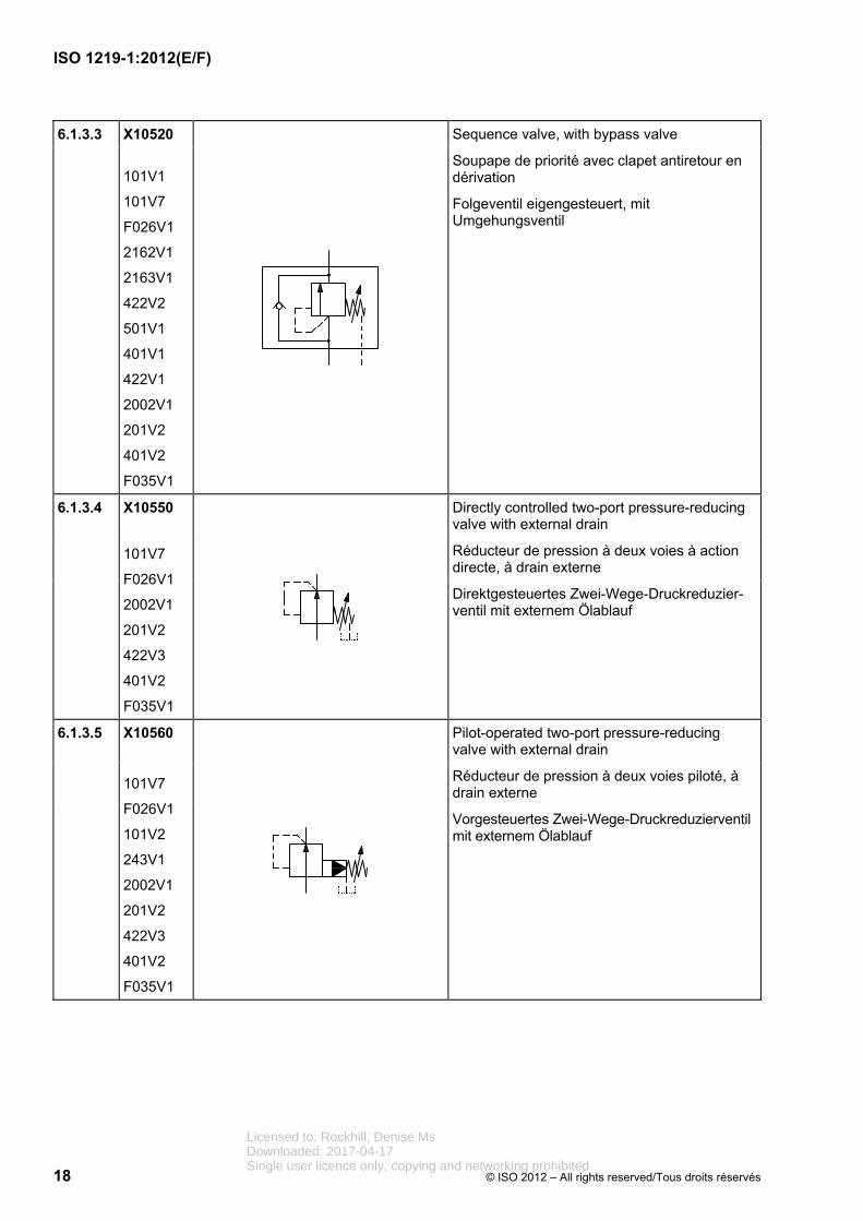
6.1.3.3 X10520
101V1
101V7
F026V1
2162V1
2163V1
422V2
501V1
401V1
422V1
2002V1
201V2
401V2
F035V1
Sequence valve, with bypass valve
Soupape de priorité avec clapet antiretour en dérivation
Folgeventil eigengesteuert, mit Umgehungsventil
6.1.3.4 X10550
101V7
F026V1
2002V1
201V2
422V3
401V2
F035V1
Directly controlled two-port pressure-reducing valve with external drain
Réducteur de pression à deux voies à action directe, à drain externe
Direktgesteuertes Zwei-Wege-Druckreduzier-ventil mit externem Ölablauf
6.1.3.5 X10560
101V7
F026V1
101V2
243V1
2002V1
201V2
422V3
401V2
F035V1
Pilot-operated two-port pressure-reducing valve with external drain
Réducteur de pression à deux voies piloté, à drain externe
Vorgesteuertes Zwei-Wege-Druckreduzierventil mit externem Ölablauf
Licensed to: Rockhill, Denise MsDownloaded: 2017-04-17Single user licence only, copying and networking prohibited

ISO 1219-1:2012(E/F)
© ISO 2012 – All rights reserved/Tous droits réservés 19
6.1.3.6 X10580
101V7
101V1
F026V1
2002V1
201V2
422V2
2162V1
2163V1
501V1
401V1
401V2
Pressure-relief and anti-cavitation valves for protecting two supply lines
Limiteurs de pression et clapets anticavitation pour protéger deux conduites d'alimentation
Druckbegrenzungsventile und Nachsaugventile zur Absicherung zweier Verbraucherleitungen
6.1.3.7 X10590
101V7
101V1
F026V1
422V2
2177V1
101V2
243V1
2002V1
201V2
2162V1
2163V1
501V1
401V1
422V1
401V2
Accumulator-charging valve with a fixed switching-pressure differential
Valve de gonflage d'accumulateur à pression différentielle fixe
Speicherladeventil mit fester Schaltdruckdifferenz
Licensed to: Rockhill, Denise MsDownloaded: 2017-04-17Single user licence only, copying and networking prohibited

ISO 1219-1:2012(E/F)
20 © ISO 2012 – All rights reserved/Tous droits réservés
6.1.3.8 X10600
101V7
F026V1
422V2
101V2
2002V1
201V2
2172V1
212V1
422V1
501V1
401V1
101V1
243V1
401V2
F035V1
Hydraulic pilot-controlled pressure-relief valve with electrically operated activation to a set pressure
Limiteur hydraulique de pression piloté, pression de réglage activée par commande électrique
Hydraulisch vorgesteuertes Druckbegrenzungsventil mit elektrisch betätigter Aktivierung auf eingestellten Druck
6.1.3.9 X10610
101V7
F028V1
422V4
2002V1
201V2
401V2
Three-port pressure-reducing valve
When the set pressure is exceeded, the valve opens the outlet port to the tank.
Réducteur de pression à trois voies
Le réducteur ouvre l'orifice de raccordement de sortie vers le réservoir dès qu'une pression de réglage est dépassée.
Drei-Wege-Druckreduzierventil
Bei Überschreiten des eingestellten Drucks öffnet das Ventil den Ausgangsanschluss zum Behälter.
Licensed to: Rockhill, Denise MsDownloaded: 2017-04-17Single user licence only, copying and networking prohibited

ISO 1219-1:2012(E/F)
© ISO 2012 – All rights reserved/Tous droits réservés 21
6.1.4 Flow-control valves
Distributeurs de commande de débit
Schalt-Stromventile
Reg. No.
N° d'enreg.
Regist Nr.
Graphic
Graphique
Grafik
Description
Description
Beschreibung
6.1.4.1 X10630
401V1
2031V1
201V4
Flow-control valve, adjustable
Gicleur réglable
Drosselventil, einstellbar
6.1.4.2 X10640
401V1
2031V1
201V4
2162V1
2163V1
501V1
101V1
401V2
Flow-control valve, adjustable, with free flow in one direction
Gicleur avec clapet, réglable, écoulement libre dans un sens
Drossel-Rückschlagventil, einstellbar, freier Durchfluss in einer Richtung
6.1.4.3 X10650
101V7
F028V1
2172V1
RF028
2002V1
402V5
712V1
401V2
Flow-control valve, operated by roller plunger, spring-returned
Limiteur de débit réglable, commande mécanique par galet, rappel par ressort
Verstellbares Drosselventil, Betätigung mittels Rollenstößel, Federrückstellung
Licensed to: Rockhill, Denise MsDownloaded: 2017-04-17Single user licence only, copying and networking prohibited

ISO 1219-1:2012(E/F)
22 © ISO 2012 – All rights reserved/Tous droits réservés
6.1.4.4 X10660
F022V1
203V2
2162V1
2163V1
242V1
501V1
101V1
401V1
401V2
Two-port flow-control valve, preset, for one direction of flow, largely independent of viscosity and pressure differential, adjustable, with bypass check valve
Régulateur de débit à deux voies, à réglage fixe, pour un sens d'écoulement, peu sensible à la viscosité et à la pression différentielle, réglable, avec clapet antiretour de bipasse
Zwei-Wege-Stromventil, fest eingestellt, für eine Strömungsrichtung, weitgehend unabhängig von Viskosität und Druckdifferenz, einstellbar, mit Umgehungsrückschlagventil
6.1.4.5 X10670
F022V1
201V3
242V1
501V1
101V1
401V1
401V2
Three-port flow-control valve, adjustable, that divides the inlet flow into a fixed flow and a residual flow
Régulateur de débit à trois voies, réglable, qui divise le débit d'entrée entre un débit constant et un débit résiduel
Drei-Wege-Stromregelventil, einstellbar, teilt den Eingangsvolumenstrom in einen Konstant-strom und einen Reststrom
6.1.4.6 X10680
F022V1
242V1
101V1
401V1
501V2
401V2
Flow divider that divides the inlet flow into two outlet flows
Diviseur de débit qui divise le débit d'entrée en deux débits de sortie.
Volumenstromteiler teilt den Eingangsvolumenstrom in zwei Ausgangsvolumenströme.
6.1.4.7 X10690
F022V1
242V1
101V1
401V1
501V2
401V2
Flow-combining valve that maintains the two inlet flows constant in relation to each other
Sommateur de débit qui maintient deux débits d'entrée à une valeur constante l'un par rapport à l'autre.
Volumenstromsummierer hält zwei Eingangsvolumenströme zueinander konstant.
Licensed to: Rockhill, Denise MsDownloaded: 2017-04-17Single user licence only, copying and networking prohibited

ISO 1219-1:2012(E/F)
© ISO 2012 – All rights reserved/Tous droits réservés 23
6.1.5 Non-return (check) valves and shuttle valves
Clapets antiretour et sélecteurs de circuit
Rückschlagventile und Wechselventile
Reg. No.
N° d'enreg.
Regist Nr.
Graphic
Graphique
Grafik
Description
Description
Beschreibung
6.1.5.1 X10700
2162V1
2163V1
401V1
Non-return valve, free flow possible in only one direction
Clapet antiretour, écoulement possible dans un seul sens
Rückschlagventil, Durchfluss nur in einer Richtung möglich
6.1.5.2 X10710
2162V1
2163V1
401V1
2002V1
Non-return valve with spring, free flow possible in only one direction, normally closed
Clapet antiretour à ressort, écoulement possible dans un seul sens, normalement fermé
Rückschlagventil mit Feder, Durchfluss nur in eine Richtung möglich, Ruhestellung geschlossen
6.1.5.3 X10720
2162V1
2163V1
401V1
422V1
2002V1
101V1
401V2
F035V1
Pilot-operated non-return valve with spring, in which pilot pressure allows free flow in both directions
Clapet antiretour à déverrouillage à ressort, dans lequel l'écoulement est possible dans les deux sens par pression de pilotage
Entsperrbares Rückschlagventil mit Feder, durch Steuerdruck Durchfluss in beide Richtungen möglich
Licensed to: Rockhill, Denise MsDownloaded: 2017-04-17Single user licence only, copying and networking prohibited

ISO 1219-1:2012(E/F)
24 © ISO 2012 – All rights reserved/Tous droits réservés
6.1.5.4 X10730
101V1
2162V1
2163V1
422V1
401V1
501V1
401V2
Double non-return valve, pilot-operated
Clapet antiretour double, déverrouillable
Doppelrückschlagventil, entsperrbar
6.1.5.5 X10740
101V16
2162V1
2163V1
501V2
401V1
401V2
Shuttle valve (OR function), in which the inlet that experiences the higher pressure is automatically connected to the outlet
Sélecteur de circuit (fonction OU), dans lequel l'entrée sur laquelle s'applique la pression la plus élevée est reliée automatiquement à la sortie
Wechselventil (ODER-Funktion), der Eingang, an dem der höhere Druck anliegt, wird automatisch mit dem Ausgang verbunden
Licensed to: Rockhill, Denise MsDownloaded: 2017-04-17Single user licence only, copying and networking prohibited
ISO 1219-1:2012(E/F)
© ISO 2012 – All rights reserved/Tous droits réservés 25
6.1.6 Proportional directional control valves
Distributeurs proportionnels de commande directe
Stetig-Wegeventile
Reg. No.
N° d'enreg.
Regist Nr.
Graphic
Graphique
Grafik
Description
Description
Beschreibung
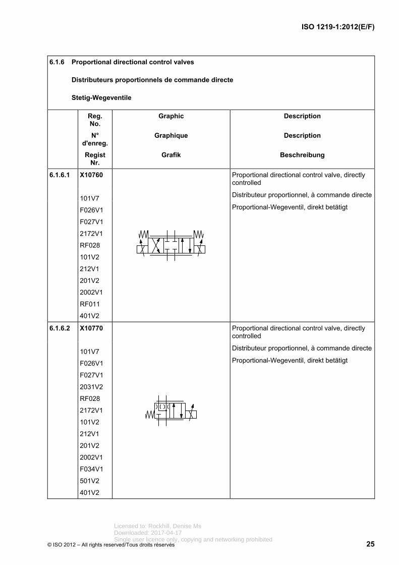
6.1.6.1 X10760
101V7
F026V1
F027V1
2172V1
RF028
101V2
212V1
201V2
2002V1
RF011
401V2
Proportional directional control valve, directly controlled
Distributeur proportionnel, à commande directe
Proportional-Wegeventil, direkt betätigt
6.1.6.2 X10770
101V7
F026V1
F027V1
2031V2
RF028
2172V1
101V2
212V1
201V2
2002V1
F034V1
501V2
401V2
Proportional directional control valve, directly controlled
Distributeur proportionnel, à commande directe
Proportional-Wegeventil, direkt betätigt
Licensed to: Rockhill, Denise MsDownloaded: 2017-04-17Single user licence only, copying and networking prohibited

ISO 1219-1:2012(E/F)
26 © ISO 2012 – All rights reserved/Tous droits réservés
6.1.6.3 X10780
101V7
F026V1
F027V1
RF028
101V2
243V1
212V1
201V2
2002V1
753V1
F045V1
234V1
401V2
101V5
F052V1
2172V1
F046V1
RF011
Proportional directional control valve, pilot-operated, with closed-loop position control of the main and pilot stages, with integrated electronics
Distributeur proportionnel, piloté, avec régulation de la position de l'étage principal et de l'étage de pilotage, électronique intégrée
Proportional-Wegeventil, vorgesteuert, mit Lageregelung der Haupt- und der Vorsteuerstufe, mit integrierter Elektronik
Licensed to: Rockhill, Denise MsDownloaded: 2017-04-17Single user licence only, copying and networking prohibited

ISO 1219-1:2012(E/F)
© ISO 2012 – All rights reserved/Tous droits réservés 27
6.1.6.4 X10790
101V7
F026V1
F027V1
RF028
101V2
243V1
212V1
201V2
101V5
F052V1
2002V1
753V1
F045V1
234V1
401V2
2172V1
F046V1
RF011
Servo-valve, pilot-operated, with closed-loop position control of the main and pilot stages, with integrated electronics
Servodistributeur piloté à commande avec régulation de la position de l'étage principal et de l'étage de pilotage, électronique intégrée
Servoventil vorgesteuert mit einem Stellmagneten, mit Lageregelung der Haupt- und der Vorsteuerstufe, mit integrierter Elektronik
6.1.6.5 X10800
101V7
F026V1
F027V1
F033V1
2031V2
RF028
101V2
243V1
212V4
201V2
402V1
241V1
401V2
501V2
101V5
F052V1
RF011
Servo-valve, pilot-operated, pilot stage with electrical control mechanism with two coils, continuously controlled in both directions, with mechanical feedback of the valve-spool position to the pilot stage, with integrated electronics
Servodistributeur piloté, étage pilote à dispositif électrique de commande à deux enroulements actifs en permanence dans les deux sens, à rappel mécanique de la position du tiroir de la valve sur l'étage de pilotage, électronique intégrée
Servoventil, vorgesteuert, Vorsteuerstufe mit elektrischer Betätigungseinrichtung mit zwei Wicklungen in beiden Richtungen stetig wirkend, mit mechanischer Rückführung der Lage des Ventilschiebers auf die Vorsteuerstufe, mit integrierter Elektronik
Licensed to: Rockhill, Denise MsDownloaded: 2017-04-17Single user licence only, copying and networking prohibited

ISO 1219-1:2012(E/F)
28 © ISO 2012 – All rights reserved/Tous droits réservés
6.1.6.6 X10810
101V7
F026V1
F027V1
2172V1
RF028
101V13
F004V1
101V14
402V1
241V1
F019V2
211V1
F002V1
402V5
101V1
401V1
401V2
Electro-hydraulic linear drive consisting of cylinder with servo-valve and stepping motor, mechanical feedback of the cylinder position
Entraînement linéaire électrohydraulique, composé du vérin et du servodistributeur avec moteur pas à pas, rétroaction mécanique de la position du vérin
Elektrohydraulischer Linearantrieb, bestehend aus Zylinder und Servoventil mit Schrittmotor, mechanische Rückführung der Zylinderposition
6.1.6.7 X10820
101V7
F026V1
F027V1
2172V1
RF028
F034V1
2002V1
101V2
212V1
201V2
101V5
F052V1
753V1
F045V1
234V1
501V2
401V2
F046V1
Servo-valve with preferred position in case of a power failure, electrical feedback and integral electronics
Servodistributeur avec position préférentielle en cas de panne de courant, rétroaction électrique, électronique intégrée
Servoventil mit Vorzugsstellung bei Stromausfall, elektrischer Rückführung und integrierter Elektronik
Licensed to: Rockhill, Denise MsDownloaded: 2017-04-17Single user licence only, copying and networking prohibited

ISO 1219-1:2012(E/F)
© ISO 2012 – All rights reserved/Tous droits réservés 29
6.1.7 Proportional pressure control valves
Distributeurs proportionnels de commande de pression
Stetig-Druckventile
Reg. No.
N° d'enreg.
Regist Nr.
Graphic
Graphique
Grafik
Description
Description
Beschreibung
6.1.7.1 X10830
101V7
F026V1
422V2
2002V1
101V2
212V1
201V2
401V2
Proportional pressure-relief valve, directly controlled, in which the solenoid controls the valve poppet by means of a spring
Limiteur de pression proportionnel, à commande directe, l'électroaimant agissant sur le ressort de clapet de valve
Proportional-Druckbegrenzungsventil, direkt betätigt, Magnet wirkt über Feder auf Ventilkegel
6.1.7.2 X10840
101V7
F026V1
422V2
101V2
212V1
201V2
401V2
101V5
F052V1
Proportional pressure-relief valve, directly controlled by a solenoid acting on a valve poppet, with integral electronics
Limiteur de pression proportionnel, à commande directe, l'électroaimant agissant sur le clapet du distributeur, électronique intégrée
Proportional-Druckbegrenzungsventil, direkt betätigt, Magnet wirkt auf Ventilkegel, mit integrierter Elektronik
Licensed to: Rockhill, Denise MsDownloaded: 2017-04-17Single user licence only, copying and networking prohibited

ISO 1219-1:2012(E/F)
30 © ISO 2012 – All rights reserved/Tous droits réservés
6.1.7.3 X10850
101V7
F026V1
422V2
F046V1
2002V1
101V2
212V1
201V2
101V5
F052V1
753V1
F045V1
234V1
401V2
F046V1
Proportional pressure-relief valve, directly controlled, with closed-loop position control of the solenoid and with integral electronics
Limiteur de pression proportionnel, à commande directe, avec régulation de la position de l'électroaimant, électronique intégrée
Proportional-Druckbegrenzungsventil, direkt betätigt, mit Lageregelung des Magneten und mit integrierter Elektronik
6.1.7.4 X10860
101V7
F026V1
422V2
2002V1
101V2
212V1
201V2
401V2
243V1
753V1
F045V1
234V1
F046V1
F035V1
Proportional pressure-relief valve, pilot-operated with electrical sensing of the solenoid position, with external pilot drain
Limiteur de pression proportionnel, piloté, avec détection électrique de la position de l'électroaimant, à drain externe de pilotage
Proportional-Druckbegrenzungsventil, vorgesteuert, mit elektrischer Positionserfassung des Magneten, mit externem Steuerölablauf
Licensed to: Rockhill, Denise MsDownloaded: 2017-04-17Single user licence only, copying and networking prohibited

ISO 1219-1:2012(E/F)
© ISO 2012 – All rights reserved/Tous droits réservés 31
6.1.7.5 X10870
101V7
F028V1
422V4
101V2
243V1
2002V1
212V1
201V2
101V5
F052V1
753V1
F045V1
234V1
422V1
401V1
401V2
F046V1
2061V1
Three-port proportional pressure-reducing valve with closed-loop position control of the solenoid and integrated electronics
Réducteur de pression proportionnel trois voies, piloté, avec régulation de la position de l'électroaimant, électronique intégrée
Drei-Wege-Proportional-Druckreduzierventil, vorgesteuert, mit Lageregelung des Magneten und integrierter Elektronik
6.1.7.6 X10880
101V7
F026V1
101V2
243V1
212V1
201V2
101V5
F052V1
422V2
401V2
2002V1
Proportional pressure-relief valve, pilot-operated, with integral electronics and additional pilot stage for manual pressure adjustment or maximum pressure-relief function, with external drain
Limiteur de pression proportionnel, piloté, avec électronique intégrée et étage de pilotage supplémentaire pour réglage manuel de pression ou limitation de pression maximale de sécurité, à drain externe
Proportional-Druckbegrenzungsventil, vorgesteuert, mit integrierter Elektronik, mit zusätzlicher Vorsteuerstufe für manuelle Druckeinstellung bzw. Maximaldruck-Absicherung, mit externem Ölablauf
Licensed to: Rockhill, Denise MsDownloaded: 2017-04-17Single user licence only, copying and networking prohibited

ISO 1219-1:2012(E/F)
32 © ISO 2012 – All rights reserved/Tous droits réservés
6.1.8 Proportional flow control valves
Distributeurs proportionnels de commande de débit
Stetig-Stromventile
Reg. No.
N° d'enreg.
Regist Nr.
Graphic
Graphique
Grafik
Description
Description
Beschreibung
6.1.8.1 X10890
101V7
F028V1
2172V1
RF028
2002V1
101V2
212V1
201V2
401V2
Proportional flow-control valve, directly controlled
Vanne de débit proportionnelle à commande directe
Proportional-Stromventil, direkt betätigt
6.1.8.2 X10900
101V7
F027V1
2172V1
RF028
2002V1
101V2
212V1
201V2
101V5
F052V1
753V1
F045V1
234V1
401V2
RF011
F046V1
Proportional flow-control valve, directly controlled, with closed-loop position control of the solenoid and integrated electronics
Vanne de débit proportionnelle à commande directe, avec régulation de la position de l'électroaimant, électronique intégrée
Proportional-Stromventil, direkt betätigt, mit Lageregelung des Magneten und integrierter Elektronik
Licensed to: Rockhill, Denise MsDownloaded: 2017-04-17Single user licence only, copying and networking prohibited

ISO 1219-1:2012(E/F)
© ISO 2012 – All rights reserved/Tous droits réservés 33
6.1.8.3 X10910
101V7
F026V1
2172V1
RF028
2002V1
101V2
243V1
212V1
201V2
753V1
F045V1
234V1
101V5
F052V1
401V2
RF011
F046V1
Proportional flow-control valve, pilot-operated, with position control of the main and pilot stage, integrated electronics
Vanne de débit proportionnelle, pilotée, avec régulation de la position de l'étage principal et de l'étage de pilotage, électronique intégrée
Proportional-Stromventil, vorgesteuert, mit Lageregelung der Haupt- und Vorsteuerstufe, integrierte Elektronik
6.1.8.4 X10920
201V3
242V1
101V2
212V4
201V2
401V1
101V1
F022V1
Adjustable-orifice flow-control valve using a proportional solenoid that is not affected by changes in viscosity
Vanne de débit à étrangleur, à réglage par électroaimant pour compenser les variations de viscosité
Stromventil mit durch Proportionalmagnet einstellbarer Blende zum Ausgleich von Viskositätsänderungen
Licensed to: Rockhill, Denise MsDownloaded: 2017-04-17Single user licence only, copying and networking prohibited

ISO 1219-1:2012(E/F)
34 © ISO 2012 – All rights reserved/Tous droits réservés
6.1.9 Two-port slip-in cartridge valves
Distributeurs à cartouche à bride à deux orifices
Zwei-Wege-Einbauventile
Reg. No.
N° d'enreg.
Regist Nr.
Graphic
Graphique
Grafik
Description
Description
Beschreibung
6.1.9.1 X10930
F010V1
101V9
2002V2
401V2
Pressure-control and directional control valve cartridge, poppet design, area ratio 1:1
Élément à cartouche, fonctions de pression et de distribution, conception à clapet, rapport de surfaces 1:1
Druckventil- und Wegeventil-Einbausatz, Sitzausführung, Flächenverhältnis 1:1
6.1.9.2 X10940
F010V1
101V9
2002V2
401V2
Pressure-control and directional control valve cartridge, poppet design, normally open, area ratio 1:1
Élément à cartouche, fonctions de pression et de distribution, conception à clapet, normalement ouvert, rapport de surfaces 1:1
Druckventil- und Wegeventil-Einbausatz, Sitzausführung, in Ausgangsstellung offen, Flächenverhältnis 1:1
6.1.9.3 X10950
F010V1
F011V1
2002V2
401V2
Directional control valve cartridge, poppet design, with throttle nose, area ratio u 0,7
Élément à cartouche, fonction de distribution, conception à clapet, avec fonction d'étranglement, rapport de surfaces u 0,7
Wegeventil-Einbausatz, Sitzausführung, mit Drosselzapfen, Flächenverhältnis u 0,7
Licensed to: Rockhill, Denise MsDownloaded: 2017-04-17Single user licence only, copying and networking prohibited

ISO 1219-1:2012(E/F)
© ISO 2012 – All rights reserved/Tous droits réservés 35
6.1.9.4 X10960
F010V1
F012V1
2002V2
401V2
Directional control valve cartridge, poppet design, with throttle nose, area ratio 0,7
Élément à cartouche, fonction de distribution, conception à clapet, avec fonction d'étranglement, rapport de surfaces 0,7
Wegeventil-Einbausatz, Sitzausführung, mit Drosselzapfen, Flächenverhältnis 0,7
6.1.9.5 X10970
F010V1
F011V1
2002V2
401V2
Directional control valve cartridge, poppet design, area ratio u 0,7
Élément à cartouche, fonction de distribution, conception à clapet, rapport de surfaces u 0,7
Wegeventil-Einbausatz, Sitzausführung, Flächenverhältnis u 0,7
6.1.9.6 X10980
F010V1
F012V1
2002V2
401V2
Directional control valve cartridge, poppet design, area ratio 0,7
Élément à cartouche, fonction de distribution, conception à clapet, rapport de surfaces 0,7
Wegeventil-Einbausatz, Sitzausführung, Flächenverhältnis 0,7
6.1.9.7 X10990
F013V1
F014V1
2002V2
401V2
Active-control, directional control valve cartridge, poppet design, opened by pilot pressure
Élément à cartouche, fonction de distribution, contrôle actif, conception à clapet, ouverture par pression de pilotage
Aktive Ansteuerung, Wegeventil-Einbausatz, Sitzausführung, durch Steuerdruck geöffnet
6.1.9.8 X11000
F013V1
F015V1
2002V2
401V2
Active-control, directional control valve cartridge without area difference on side B
Élément à cartouche, fonction de distribution, contrôle actif, sans différence de surfaces du côté B
Aktive Ansteuerung, Wegeventil-einsatz ohne Flächendifferenz an Seite B
Licensed to: Rockhill, Denise MsDownloaded: 2017-04-17Single user licence only, copying and networking prohibited

ISO 1219-1:2012(E/F)
36 © ISO 2012 – All rights reserved/Tous droits réservés
6.1.9.9 X11010
F010V1
F011V1
2002V2
2031V2
401V2
RF034
422V1
Directional control valve cartridge, non-return function, poppet design, internal pilot supply, with replaceable orifice (restrictor)
Élément à cartouche, fonction antiretour, conception à clapet, alimentation interne d'huile de pilotage, à gicleur interchangeable
Wegeventil-Einbausatz, Wegeventileinsatz, Rückschlag-ventilfunktion, Sitzausführung, interne Steuerölversorgung, mit auswechselbarer Düse
6.1.9.10 X11020
101V10
101V11
2002V2
2031V2
401V1
501V2
401V2
422V1
Cartridge for pressure-relief and limitation functions, spool design, normally closed
Élément à cartouche pour fonction de décharge et de limitation, conception à tiroir, normalement fermé
Einbausatz für Entlastungs- und Begrenzungs-funktion, Schieberausführung, in Ausgangsstellung geschlossen
6.1.9.11 X11030
101V10
101V11
2002V2
2031V2
2162V2
401V1
422V1
501V2
401V2
2163V2
Pressure-reducing valve cartridge, spool design, normally closed, with integrated non-return valve
Élément à cartouche réducteur de pression, conception à tiroir, normalement fermé, avec clapet antiretour intégré
Druckreduzierventil-Einbausatz, Schieberausführung, in Ausgangsstellung geschlossen, mit eingebautem Rückschlagventil
Licensed to: Rockhill, Denise MsDownloaded: 2017-04-17Single user licence only, copying and networking prohibited

ISO 1219-1:2012(E/F)
© ISO 2012 – All rights reserved/Tous droits réservés 37
6.1.9.12 X11040
101V10
101V11
2002V2
2031V2
2162V2
401V1
422V1
501V2
401V2
2163V2
Pressure-reducing valve cartridge, spool design, normally open, with integrated non-return valve
Élément à cartouche réducteur de pression, conception à tiroir, normalement ouvert, avec clapet antiretour intégré
Druckreduzierventil-Einbausatz, Schieberausführung, in Ausgangsstellung offen, mit eingebautem Rückschlagventil
6.1.9.13 X11050
F016V1
Control cover without ports
Couvercle de commande sans orifices
Steuerdeckel ohne Anschlüsse
6.1.9.14 X11060
F016V1
2031V2
RF034
422V1
F035V1
Control cover with pilot port
Couvercle de commande avec orifice de pilotage
Steuerdeckel mit Steueranschluss
6.1.9.15 X11070
F016V1
2031V2
RF034
2172V1
F020V1
201V1
501V1
422V1
401V1
F035V1
401V2
Control cover with pilot port, with adjustable stroke limiter and remote-control port
Couvercle de commande avec orifice de pilotage, avec limiteur de course et orifice de commande à distance
Steuerdeckel mit Steueranschluss, einstellbarer Hubbegrenzung und Fernsteueranschluss
Licensed to: Rockhill, Denise MsDownloaded: 2017-04-17Single user licence only, copying and networking prohibited

ISO 1219-1:2012(E/F)
38 © ISO 2012 – All rights reserved/Tous droits réservés
6.1.9.16 X11080
F016V1
2031V2
RF034
501V1
422V1
F035V1
Control cover for mounting additional elements
Couvercle de commande pour montage d'éléments supplémentaires
Steuerdeckel für den Aufbau weiterer Elemente
6.1.9.17 X11090
F016V1
2031V2
RF034
101V16
2162V1
2163V1
501V2
401V1
422V1
F035V1
Control cover with hydraulically controlled shuttle valve
Couvercle de commande avec sélecteur de circuit à commande hydraulique
Steuerdeckel mit hydraulisch schaltbarem Wechselventil
6.1.9.18 X11100
F016V1
2031V2
RF034
101V16
2162V1
2163V1
501V2
401V1
422V1
501V1
F035V1
Control cover with shuttle valve
Couvercle de commande avec sélecteur de circuit
Steuerdeckel mit Wechselventil
Licensed to: Rockhill, Denise MsDownloaded: 2017-04-17Single user licence only, copying and networking prohibited

ISO 1219-1:2012(E/F)
© ISO 2012 – All rights reserved/Tous droits réservés 39
6.1.9.19 X11110
F016V1
2031V2
RF034
101V16
2162V1
2163V1
501V2
401V1
422V1
F035V1
Control cover with shuttle valve for mounting additional elements
Couvercle de commande avec sélecteur de circuit pour montage d'éléments supplémentaires
Steuerdeckel mit Wechselventil und für Aufbau weiterer Elemente
6.1.9.20 X11120
F016V1
2031V2
RF034
501V1
101V7
F026V1
2002V1
422V2
201V2
422V1
F035V1
Control cover with pressure-relief function
Couvercle de commande avec fonction de limitation de pression
Steuerdeckel mit Druckbegrenzungsfunktion
Licensed to: Rockhill, Denise MsDownloaded: 2017-04-17Single user licence only, copying and networking prohibited

ISO 1219-1:2012(E/F)
40 © ISO 2012 – All rights reserved/Tous droits réservés
6.1.9.21 X11130
F016V1
2031V2
RF034
501V1
101V7
F026V1
2002V1
422V2
101V2
243V1
201V2
422V1
F035V1
Control cover with pressure-relief function and hydraulic unloading
Couvercle de commande avec fonction de limitation de pression et décharge hydraulique
Steuerdeckel mit Druckbegrenzungsfunktion und hydraulischer Entlastung
6.1.9.22 X11140
F016V1
2031V2
501V1
101V7
F026V1
2002V1
422V2
401V2
2031V1
242V1
201V2
422V1
1012V1
F035V1
Control cover with pressure-relief function with a flow-control valve for limiting the pilot flow
Couvercle de commande avec fonction de limitation de pression avec régulateur de débit pour limiter le débit de pilotage
Steuerdeckel mit Druckbegrenzungsfunktion mit Stromregler zur Begrenzung des Steuerölstroms
Licensed to: Rockhill, Denise MsDownloaded: 2017-04-17Single user licence only, copying and networking prohibited
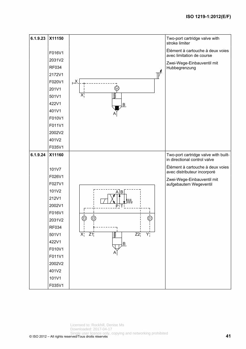
ISO 1219-1:2012(E/F)
© ISO 2012 – All rights reserved/Tous droits réservés 41
6.1.9.23 X11150
F016V1
2031V2
RF034
2172V1
F020V1
201V1
501V1
422V1
401V1
F010V1
F011V1
2002V2
401V2
F035V1
Two-port cartridge valve with stroke limiter
Élément à cartouche à deux voies avec limitation de course
Zwei-Wege-Einbauventil mit Hubbegrenzung
6.1.9.24 X11160
101V7
F026V1
F027V1
101V2
212V1
2002V1
F016V1
2031V2
RF034
501V1
422V1
F010V1
F011V1
2002V2
401V2
101V1
F035V1
Two-port cartridge valve with built-in directional control valve
Élément à cartouche à deux voies avec distributeur incorporé
Zwei-Wege-Einbauventil mit aufgebautem Wegeventil
Licensed to: Rockhill, Denise MsDownloaded: 2017-04-17Single user licence only, copying and networking prohibited

ISO 1219-1:2012(E/F)
42 © ISO 2012 – All rights reserved/Tous droits réservés
6.1.9.25 X11170
101V7
F026V1
F027V1
101V2
212V1
2002V1
F016V1
2031V2
RF034
422V1
F013V1
2002V2
401V2
F014V1
101V1
501V1
F035V1
Two-port cartridge valve with active control, with built-in directional control valve
Élément à cartouche à deux voies, contrôle actif, avec distributeur incorporé
Aktiv aufsteuerbares Zwei-Wege-Einbauventil mit aufgebautem Wegeventil
6.1.9.26 X11180
F010V1
2002V2
401V2
F016V1
2031V2
RF034
501V1
101V7
F026V1
2002V1
422V2
101V9
201V2
401V1
422V1
F035V1
Two-port cartridge valve with pressure-relief function
Élément à cartouche à deux voies avec fonction de limitation de pression
Zwei-Wege-Einbauventil mit Druckbegrenzungsfunktion
Licensed to: Rockhill, Denise MsDownloaded: 2017-04-17Single user licence only, copying and networking prohibited

ISO 1219-1:2012(E/F)
© ISO 2012 – All rights reserved/Tous droits réservés 43
6.1.9.27 X11190
101V7
F026V1
F027V1
2172V1
2002V1
101V2
201V2
F016V1
2031V2
RF034
501V1
422V1
F010V1
101V1
2002V2
401V2
101V9
422V2
401V1
F035V1
Two-port cartridge valve with pressure-relief function and selectable second pressure stage
Élément à cartouche à deux voies avec fonction de limitation de pression et possibilité de sélectionner un deuxième étage de pression
Zwei-Wege-Einbauventil mit Druckbegrenzungsfunktion und wählbarer zweiten Druckstufe
Licensed to: Rockhill, Denise MsDownloaded: 2017-04-17Single user licence only, copying and networking prohibited
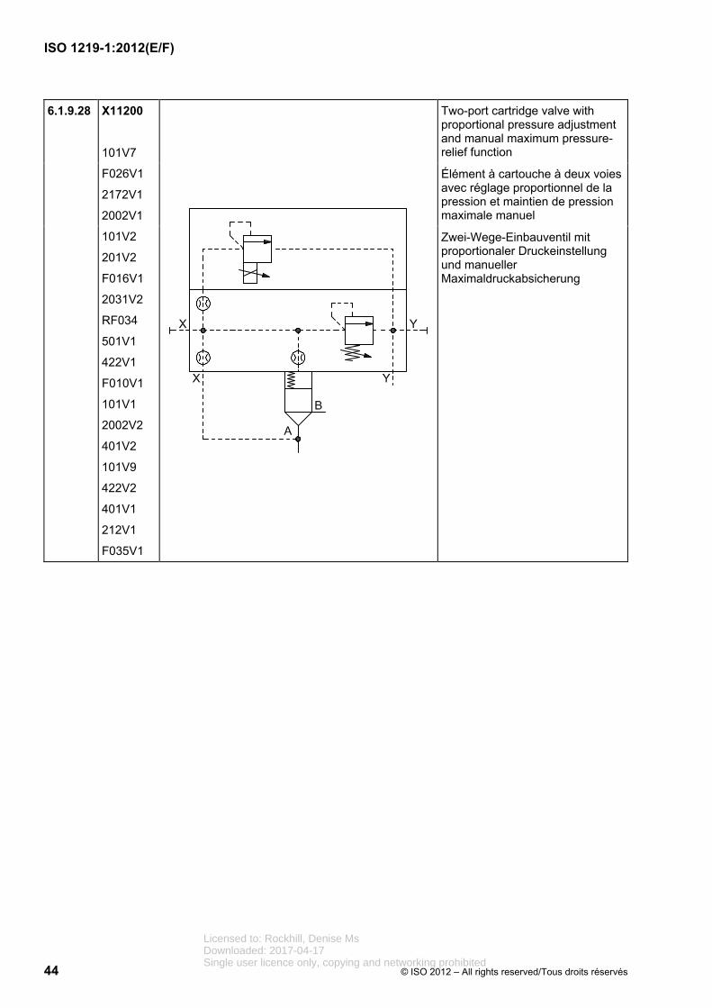
ISO 1219-1:2012(E/F)
44 © ISO 2012 – All rights reserved/Tous droits réservés
6.1.9.28 X11200
101V7
F026V1
2172V1
2002V1
101V2
201V2
F016V1
2031V2
RF034
501V1
422V1
F010V1
101V1
2002V2
401V2
101V9
422V2
401V1
212V1
F035V1
Two-port cartridge valve with proportional pressure adjustment and manual maximum pressure-relief function
Élément à cartouche à deux voies avec réglage proportionnel de la pression et maintien de pression maximale manuel
Zwei-Wege-Einbauventil mit proportionaler Druckeinstellung und manueller Maximaldruckabsicherung
Licensed to: Rockhill, Denise MsDownloaded: 2017-04-17Single user licence only, copying and networking prohibited

ISO 1219-1:2012(E/F)
© ISO 2012 – All rights reserved/Tous droits réservés 45
6.1.9.29 X11210
F016V1
501V1
101V7
F026V1
2002V1
422V2
401V2
2031V1
242V1
101V10
101V11
2002V2
2162V2
401V1
422V1
201V2
2163V2
101V1
501V2
F035V1
Two-port cartridge valve with pressure-reducing function and flow-control valve, controlled by high pressure
Élément à cartouche avec fonction de réduction de pression et valve de débit, commande par haute pression
Zwei-Wege-Einbauventil mit Druckreduzierfunktion und Stromventil, hochdruckgesteuert
Licensed to: Rockhill, Denise MsDownloaded: 2017-04-17Single user licence only, copying and networking prohibited

ISO 1219-1:2012(E/F)
46 © ISO 2012 – All rights reserved/Tous droits réservés
6.1.9.30 X11220
F016V1
2031V2
RF034
501V1
101V7
F026V1
2002V1
422V2
401V2
101V10
101V11
2002V2
401V1
201V2
501V2
422V1
F035V1
Two-port cartridge valve with pressure-reducing function, controlled by low pressure
Élément à cartouche avec fonction de réduction de pression, commande par basse pression
Zwei-Wege-Einbauventil mit Druckreduzierfunktion, niederdruckgesteuert
Licensed to: Rockhill, Denise MsDownloaded: 2017-04-17Single user licence only, copying and networking prohibited

ISO 1219-1:2012(E/F)
© ISO 2012 – All rights reserved/Tous droits réservés 47
6.2 Pumps and motors
Pompes et moteurs
Pumpen und Motore
Reg. No.
N° d'enreg.
Regist Nr.
Graphic
Graphique
Grafik
Description
Description
Beschreibung
6.2.1 X11230
2065V1
243V1
F017V1
201V5
401V2
255V1
Variable-displacement pump and one direction of rotation (clockwise)
Pompe à cylindrée variable et à un sens (des aiguilles d’une montre)
Pumpe mit veränderlichem Fördervolumen und einer Drehrichtung (im Uhrzeigersinn)
6.2.2 X11240
2065V1
243V1
F017V1
201V5
401V2
255V1
422V1
F035V1
Variable-displacement pump with two directions of flow, external drain line, and one direction of rotation (clockwise)
Pompe à cylindrée variable à deux sens d'écoulement, drain externe et à un sens de rotation (des aiguilles d'une montre)
Verstellpumpe mit wechselnder Förderstromrichtung, externer Leckölleitung und einer Drehrichtung (im Uhrzeigersinn)
6.2.3 X11250
2065V1
243V2
F017V1
201V5
401V2
256V1
422V1
F035V1
Reversible pump/motor unit with two directions of flow and variable displacement, external drain line, and two directions of rotation
Groupe motopompe réversible à deux sens d'écoulement et cylindrée variable, drain externe et deux sens de rotation
Reversierbare Pumpe/Motor-Einheit mit zwei Volumenstromrichtungen und veränderlichem Verdrängungsvolumen, externe Leckölleitung und zwei Drehrichtungen
Licensed to: Rockhill, Denise MsDownloaded: 2017-04-17Single user licence only, copying and networking prohibited

ISO 1219-1:2012(E/F)
48 © ISO 2012 – All rights reserved/Tous droits réservés
6.2.4 X11260
2065V1
243V1
F017V1
401V2
255V1
Fixed displacement pump/motor unit with one direction of rotation (clockwise)
Groupe motopompe à cylindrée fixe et un sens de rotation (des aiguilles d'une montre)
Pumpe/Motor mit konstantem Verdrängungs-/Schluckvolumen und einer Drehrichtung (im Uhrzeigersinn)
6.2.5 X11270
F003V1
243V2
402V4
688V1
401V2
Pump with a limited swivel angle, lever-operated
Pompe à angle de pivotement limité, commande par levier
Pumpe mit begrenztem Schwenkwinkel, Hebelbetätigung
6.2.6 X11280
F003V1
256V1
F017V1
401V2
Rotary actuator/swivel drive with a limited swivel angle and two directions of flow
Actionneur à angle de pivotement limité et deux sens d'écoulement
Drehantrieb/Schwenkantrieb mit begrenztem Schwenkwinkel und zwei Volumenstromrichtungen
6.2.7 X11290
F003V1
256V1
F017V1
401V2
2002V1
Semi-rotary actuator/swivel drive, single-acting
Actionneur simple effet à angle de pivotement limité
Schwenkantrieb einfachwirkend, mit begrenztem Schwenkwinkel
6.2.8 X11300
2065V1
F017V1
201V5
401V2
255V1
422V1
101V2
101V1
243V1
401V1
F035V1
Variable-displacement pump, pilot- operated, with pressure compensation, one direction of rotation (clockwise) and an external drain line
Pompe à cylindrée variable avec régulateur de pression, pilotée, à un sens d'entraînement (des aiguilles d'une montre) et drain externe
Verstellpumpe mit Druckregler, vorgesteuert, einer Antriebsrichtung (im Uhrzeigersinn) und externer Leckölleitung
Licensed to: Rockhill, Denise MsDownloaded: 2017-04-17Single user licence only, copying and networking prohibited

ISO 1219-1:2012(E/F)
© ISO 2012 – All rights reserved/Tous droits réservés 49
6.2.9 X11310
2065V1
F017V1
201V5
401V2
255V1
422V1
101V2
101V1
243V1
2002V1
201V2
401V1
F035V1
Variable-displacement pump with combined pressure/flow control (load-sensing type), one drive direction (clockwise) and an external drain line
Pompe à cylindrée variable avec régulateur combiné de pression/débit (type à détection de charge), à un sens d'entraînement (des aiguilles d'une montre) et drain externe
Verstellpumpe mit kombiniertem Druck-/Stromregler (load sensing type), einer Antriebsrichtung (im Uhrzeigersinn) und externer Leckölleitung
6.2.10 X11320
2065V1
F017V1
201V5
401V2
255V2
422V1
101V2
101V1
243V1
402V5
681V2
401V1
F035V1
Variable-displacement pump with mechanical/hydraulic servo-control, one drive direction (counter-clockwise) and an external drain line
Pompe à cylindrée variable à réglage hydromécanique, à un sens d'entraînement (inverse des aiguilles d'une montre) et drain externe
Verstellpumpe mit mechanisch-hydraulischer Servoverstellung, einer Antriebsrichtung (im Gegenuhrzeiger-sinn) und externer Leckölleitung
Licensed to: Rockhill, Denise MsDownloaded: 2017-04-17Single user licence only, copying and networking prohibited

ISO 1219-1:2012(E/F)
50 © ISO 2012 – All rights reserved/Tous droits réservés
6.2.11 X11330
2065V1
F017V1
201V5
401V2
255V2
422V1
101V2
101V1
243V1
212V1
201V2
401V1
F035V1
Variable-displacement hydraulic pump with electro-hydraulic servo control, one drive direction (counter-clockwise) and an external drain line
Pompe hydraulique à cylindrée variable à réglage électrohydraulique, à un sens d'entraînement (inverse des aiguilles d'une montre) et drain externe
Hydraulische Verstellpumpe mit elektro-hydraulischer Servoverstellung, einer Antriebsrichtung (im Gegenuhrzeiger-sinn) und externer Leckölleitung
6.2.12 X11340
2065V1
F017V1
201V5
401V2
422V1
101V2
101V1
243V1
2002V1
401V1
255V1
F035V1
Variable-displacement pump with power control, one drive direction (clockwise) and an external drain line
Pompe à cylindrée variable avec régulateur de puissance, à un sens d'entraînement (des aiguilles d'une montre) et drain externe
Verstellpumpe mit Leistungsregler, einer Antriebsrichtung (im Uhrzeigersinn) und externer Leckölleitung
Licensed to: Rockhill, Denise MsDownloaded: 2017-04-17Single user licence only, copying and networking prohibited

ISO 1219-1:2012(E/F)
© ISO 2012 – All rights reserved/Tous droits réservés 51
6.2.13 X11350
2065V1
F017V1
201V5
401V2
255V1
422V1
101V2
101V1
243V1
2002V1
201V2
F020V1
201V1
501V1
401V1
F035V1
Variable-displacement pump with a two-stage adjustable stroke limited pressure/flow control, internal pilot-operated, one drive direction (clockwise) and an external drain line
Pompe à cylindrée variable avec deux étages de commande pression/débit à limite de cylindrée réglable, pilotage interne, à un sens d'entraînement (des aiguilles d'une montre) et drain externe
Verstellpumpe mit einstellbarem zwei-stufigem Druck-/Stromregler, intern vorgesteuert, mit einer Antriebsrichtung (im Uhrzeigersinn) und externer Leckölleitung
Licensed to: Rockhill, Denise MsDownloaded: 2017-04-17Single user licence only, copying and networking prohibited

ISO 1219-1:2012(E/F)
52 © ISO 2012 – All rights reserved/Tous droits réservés
6.2.14 X11360
2065V1
F017V1
201V5
401V2
255V1
422V1
101V2
101V1
243V1
2002V1
201V2
F020V1
201V1
501V1
101V7
F026V1
F027V1
212V1
401V1
F035V1
Variable-displacement pump with a two-stage adjustable limited-stroke pressure/flow-control element, electrical switchover, one drive direction (clockwise) and an external drain line
Pompe à cylindrée variable avec régulateur de pression/débit à deux positions, à commutation électrique, à un sens d'entraînement (des aiguilles d’une montre) et drain externe
Verstellpumpe mit einstellbarem zweistufigem Druck-/Stromregler, elektrisch umsteuerbar, mit einer Antriebsrichtung (im Uhrzeigersinn) und externer Leckölleitung
6.2.15 X11370
2065V1
243V1
F017V1
201V5
255V1
101V1
401V1
256V1
Hydrostatic transmission (simplified representation), drive unit consisting of one reversible, variable-displacement pump with one input direction of rotation and one fixed displacement motor with two output directions of rotation
Transmission hydrostatique (représentation simplifiée), module d'entraînement composé d'une pompe à cylindrée variable à un sens d'entraînement en rotation et moteur à cylindrée fixe à deux sens de rotation de sortie
Kompaktgetriebe (vereinfachte Darstellung), Antriebseinheit bestehend aus reversiebler Verstellpumpe mit einer Antriebsdrehrichtung und Konstantmotor mit zwei Abtriebsdrehrichtungen
Licensed to: Rockhill, Denise MsDownloaded: 2017-04-17Single user licence only, copying and networking prohibited

ISO 1219-1:2012(E/F)
© ISO 2012 – All rights reserved/Tous droits réservés 53
6.2.16 X11380
2065V1
243V1
F017V1
201V5
401V2
101V7
255V1
F035V1
Variable-displacement pump with one drive direction (clockwise) and description of the control and adjustment elements. The arrows indicating adjustability may be extended, and the control mechanisms and elements may be connected on either end of the arrow.
*** Short designation of complex controllers
Pompe à cylindrée variable à un sens d'entraînement (des aiguilles d’une montre) et descriptif de l'organe de commande et de réglage. Les flèches représentant le réglage peuvent être prolongées et les actionneurs et éléments de commande peuvent être rattachés à l'une des extrémités de la flèche.
*** Abréviation des régulateurs complexes
Verstellpumpe mit einer Antriebsrichtung (im Uhrzeigersinn) und textueller Beschreibung der Regel- und Verstelleinrichtung. Die Pfeile zur Darstellung der Verstellbarkeit können verlängert und die Betätigungs- und Regelelemente angebunden werden, entweder am Pfeilende oder an der Pfeilspitze.
*** Kurzbezeichnung komplexer Regler
6.2.17 X11430
2065V1
243V2
244V2
401V2
401V1
Pressure intensifier, continuous, which converts a pneumatic pressure p1 into a higher hydraulic pressure p2
Multiplicateur de pression, à effet continu, qui sert à convertir une pression pneumatique p1 en une pression hydraulique p2 de valeur supérieure
Druckübersetzer, kontinuierlich, der einen pneumatischen Druck p1 in einen höheren hydraulischen Druck p2 umwandelt
Licensed to: Rockhill, Denise MsDownloaded: 2017-04-17Single user licence only, copying and networking prohibited

ISO 1219-1:2012(E/F)
54 © ISO 2012 – All rights reserved/Tous droits réservés
6.3 Cylinders
Vérins
Zylinder
Reg. No.
N° d'enreg.
Regist Nr.
Graphic
Graphique
Grafik
Description
Description
Beschreibung
6.3.1 X11440
101V13
2002V3
101V14
F004V1
401V2
Single-acting, single-rod cylinder, return stroke by spring force, spring chamber with connection
Vérin simple effet, à simple tige, rappel par ressort avec retour de fuite côté ressort
Einfachwirkender Zylinder, mit einseitiger Kolbenstange, Rückhub durch Federkraft, Federraum mit Anschluss
6.3.2 X11450
101V13
101V14
F004V1
401V2
Double-acting, single-rod cylinder
Vérin à double effet, à simple tige
Doppeltwirkender Zylinder mit einseitiger Kolbenstange
6.3.3 X11460
101V13
101V14
F004V1
F004V2
101V19
201V7
401V2
Double-acting, double-rod cylinder, with different piston-rod diameters; cushioning on both sides with adjustment on right side only
Vérin à double effet, à double tige, de diamètres différents, avec amortissement de fin de course aux deux extrémités réglable du côté droit
Doppeltwirkender Zylinder mit zweiseitiger Kolbenstange mit unterschiedlichen Durchmessern, beidseitiger Endlagendämpfung auf der rechten Seite einstellbar
6.3.4 X11470
101V13
F006V1
F004V1
401V2
F020V1
203V1
Double-acting diaphragm cylinder with preset stroke limiter
Vérin à diaphragme, à double effet, avec limiteur de course préréglé
Doppeltwirkender Membranzylinder mit Hubbegrenzung, voreingestellt
Licensed to: Rockhill, Denise MsDownloaded: 2017-04-17Single user licence only, copying and networking prohibited

ISO 1219-1:2012(E/F)
© ISO 2012 – All rights reserved/Tous droits réservés 55
6.3.5 X11480
101V13
F004V1
F006V1
101V19
2002V3
2174V1
401V2
Single-acting diaphragm cylinder with cushioning on rod end, vented cap end without the possibility of a connection
Vérin à diaphragme, à simple effet avec amortissement de fin course réglable d'un côté du piston, purge d'air sans possibilité de connexion
Einfachwirkender Membranzylinder mit Endlagendämpfung auf einer Kolbenseite, mit Entlüftung ohne Anschlussmöglichkeit
6.3.6 X11490
101V22
101V18
401V2
Single-acting cylinder, plunger cylinder
Vérin à piston à simple effet, vérin plongeur
Einfachwirkender Zylinder, Plungerzylinder
6.3.7 X11500
101V22
F004V1
F004V3
401V2
Telescopic cylinder, single-acting
Vérin télescopique, à simple effet
Teleskopzylinder, einfachwirkend
6.3.8 X11510
101V22
F005V1
F005V2
401V2
Telescopic cylinder, double-acting
Vérin télescopique, à double effet
Teleskopzylinder, doppeltwirkend
6.3.9 X11520
101V13
101V14
101V19
101V20
401V2
Double-acting band-type rodless cylinder with end-position cushioning on both sides of the piston
Vérin à double effet, sans tige, ruban d'étanchéité, à amortissement de fin de course aux deux extrémités
Doppeltwirkender kolbenstangenloser Dichtband-Zylinder mit beidseitiger Endlagendämpfung
6.3.10 X11530
101V13
101V14
101V19
101V20
201V7
245V1
401V2
Double-acting cable-type rodless cylinder with adjustable end-position cushioning on both sides of the piston
Vérin sans tige à double effet, à ruban/câble à amortissement de fin de course réglable aux deux extrémités
Doppelwirkender kolbenstangenloser Zylinder, Seil-/Bandausführung mit einstellbarer Endlagendämpfung auf beiden Seiten
Licensed to: Rockhill, Denise MsDownloaded: 2017-04-17Single user licence only, copying and networking prohibited

ISO 1219-1:2012(E/F)
56 © ISO 2012 – All rights reserved/Tous droits réservés
6.3.11 X11540
101V13
101V14
753V1
F045V1
F048V1
326V1
401V2
F046V1
Double-acting magnetic-type rodless cylinder with position switch on right-hand end only
Vérin à double effet, sans tige, à entraînement magnétique et commutateur de position uniquement à l'extrémité droite
Doppelwirkender kolbenstangenloser Zylinder, magnetisch gekoppelt, Endschalter nur auf der rechten Seite
6.3.12 X11550
101V13
101V14
F004V1
655V1
F041V1
401V2
F046V1
401V1
Double-acting cylinder with detents at both ends of the stroke
Vérin à double effet avec dispositif de maintien en position aux deux extrémités de la course
Doppelwirkender Zylinder mit Raste auf beiden Seiten des Hubs
6.3.13 X11560
101V13
101V14
F004V1
753V1
F045V1
F048V1
401V2
F046V1
401V1
Double-acting cylinder, double rod, with internal limit switch on the left end, with internal mechanical control, external limit switch on the right end, tripped by the piston rod
Vérin à double effet, à double tige, avec interrupteur de fin de course côté gauche, à commande mécanique interne, interrupteur de fin de course externe côté droit, à déclenchement par la tige
Doppelwirkender Zylinder mit Endschalter auf der linken Seite, intern mechanisch betätigt, externer Endschalter auf der rechten Seite, ausgelöst durch die Kolbenstange
6.3.14 X11580
101V13
101V14
243V2
244V2
401V2
Pressure-medium converter, single-acting, which converts a pneumatic pressure into a hydraulic pressure of the same value
Échangeur de pression simple effet, qui sert à convertir une pression pneumatique en une pression hydraulique de même valeur
Druckmittelwandler, einfachwirkend, der einen pneumatischen in einen hydraulischen Druck gleicher Höhe umwandelt
Licensed to: Rockhill, Denise MsDownloaded: 2017-04-17Single user licence only, copying and networking prohibited

ISO 1219-1:2012(E/F)
© ISO 2012 – All rights reserved/Tous droits réservés 57
6.3.15 X11590
F007V1
F008V1
243V2
244V2
401V2
Pressure intensifier, single-acting, which converts a pneumatic pressure p1 into a higher hydraulic pressure p2
Multiplicateur de pression, simple effet, qui sert à convertir une pression pneumatique p1 en une pression hydraulique p2 de valeur supérieure
Druckübersetzer, einfachwirkend, der einen pneumatischen Druck p1 in einen höheren hydraulischen Druck p2 umwandelt
6.4 Accessories
Accessoires
Zubehör
6.4.1 Connections and joints
Connexions et raccordements
Verbindungen und Anschlüsse
Reg. No.
N° d'enreg.
Regist Nr.
Graphic
Graphique
Grafik
Description
Description
Beschreibung
6.4.1.1 X11670
501V1
452V1
Hose assembly
Conduite flexible
Schlauchleitung
6.4.1.2 X11680
F036V1
RF049
F002V1
401V1
401V2
Three-way rotary connection
Connexion tournante à trois voies
Dreiwege-Drehverbindung
6.4.1.3 X11690
2162V1
2172V1
401V1
401V2
Quick-action coupling without non-return valve, uncoupled
Raccord rapide sans clapet antiretour, désaccouplé
Schnelltrennkupplung ohne Rückschlagventil, entkuppelt
Licensed to: Rockhill, Denise MsDownloaded: 2017-04-17Single user licence only, copying and networking prohibited
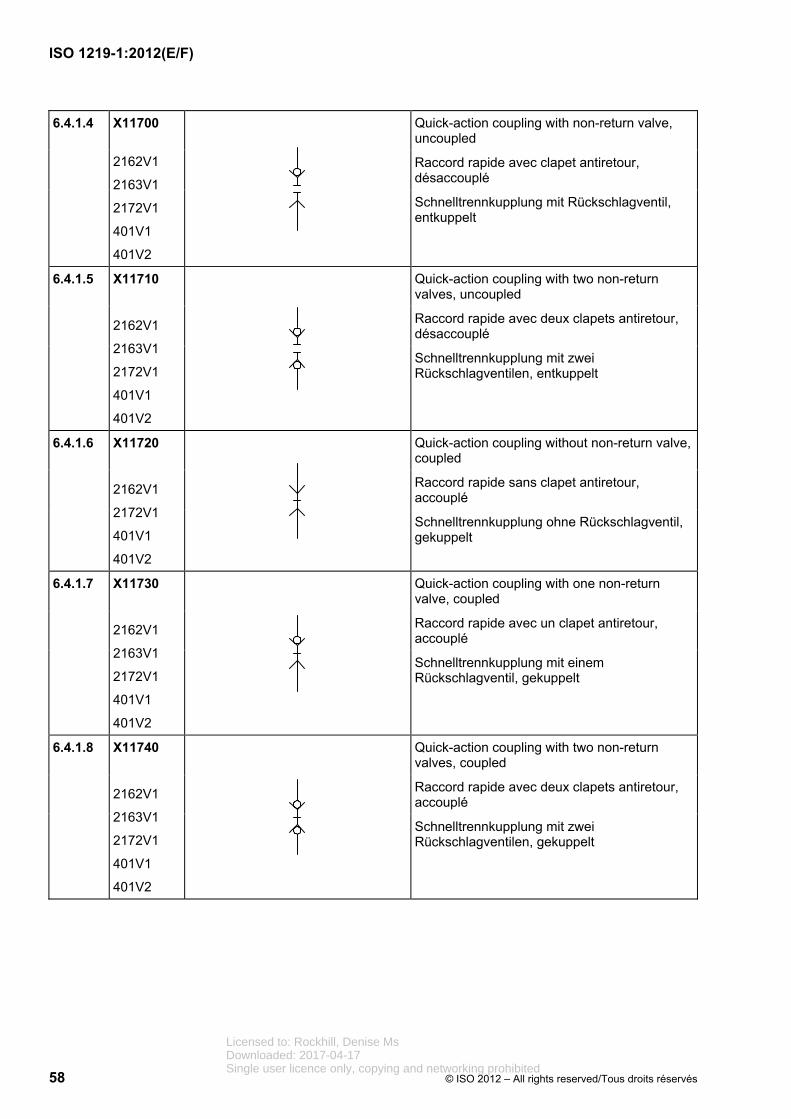
ISO 1219-1:2012(E/F)
58 © ISO 2012 – All rights reserved/Tous droits réservés
6.4.1.4 X11700
2162V1
2163V1
2172V1
401V1
401V2
Quick-action coupling with non-return valve, uncoupled
Raccord rapide avec clapet antiretour, désaccouplé
Schnelltrennkupplung mit Rückschlagventil, entkuppelt
6.4.1.5 X11710
2162V1
2163V1
2172V1
401V1
401V2
Quick-action coupling with two non-return valves, uncoupled
Raccord rapide avec deux clapets antiretour, désaccouplé
Schnelltrennkupplung mit zwei Rückschlagventilen, entkuppelt
6.4.1.6 X11720
2162V1
2172V1
401V1
401V2
Quick-action coupling without non-return valve, coupled
Raccord rapide sans clapet antiretour, accouplé
Schnelltrennkupplung ohne Rückschlagventil, gekuppelt
6.4.1.7 X11730
2162V1
2163V1
2172V1
401V1
401V2
Quick-action coupling with one non-return valve, coupled
Raccord rapide avec un clapet antiretour, accouplé
Schnelltrennkupplung mit einem Rückschlagventil, gekuppelt
6.4.1.8 X11740
2162V1
2163V1
2172V1
401V1
401V2
Quick-action coupling with two non-return valves, coupled
Raccord rapide avec deux clapets antiretour, accouplé
Schnelltrennkupplung mit zwei Rückschlagventilen, gekuppelt
Licensed to: Rockhill, Denise MsDownloaded: 2017-04-17Single user licence only, copying and networking prohibited

ISO 1219-1:2012(E/F)
© ISO 2012 – All rights reserved/Tous droits réservés 59
6.4.2 Electrical equipment
Équipement électrique
Elektrische Ausrüstung
Reg. No.
N° d'enreg.
Regist Nr.
Graphic
Graphique
Grafik
Description
Description
Beschreibung
6.4.2.1 X11750
101V5
2002V1
201V2
401V2
F050V1
Pressure switch, electro-mechanical, adjustable
Pressostat, électromécanique, réglable
Druckschalter, elektromechanisch, einstellbar
6.4.2.2 X11760
F045V1
F048V1
401V1
401V2
753V2
F046V1
201V4
Pressure converter, electronically adjustable, switching signal output
Pressostat, réglage électronique, commutation au signal de sortie
Druckschalter, elektronisch einstellbar, Ausgangssignal schaltend
6.4.2.3 X11770
F045V1
234V1
401V2
753V2
F046V1
Pressure sensor, analogue output signal
Capteur de pression, signal de sortie analogique
Drucksensor, Ausgangssignal analog
Licensed to: Rockhill, Denise MsDownloaded: 2017-04-17Single user licence only, copying and networking prohibited

ISO 1219-1:2012(E/F)
60 © ISO 2012 – All rights reserved/Tous droits réservés
6.4.3 Measuring instruments and indicators
Appareils de mesure et indicateurs
Mess- und Anzeigegeräte
Reg. No.
N° d'enreg.
Regist Nr.
Graphic
Graphique
Grafik
Description
Description
Beschreibung
6.4.3.1 X11790
101V6
148V1
F056V1
Optical indicator
Indicateur optique
Optische Anzeige
6.4.3.2 X11800
101V6
235V1
148V1
Indicator with digital display
Indicateur à affichage numérique
Digital-Anzeige
6.4.3.3 X11810
101V6
148V1
F057V1
Acoustic indicator
Indicateur acoustique
Akustischer Signalgeber
6.4.3.4 X11820
F002V1
148V1
401V2
Pressure-measuring unit (pressure gauge)
Manomètre
Druckmessgerät (Manometer)
6.4.3.5 X11830
F002V1
148V1
401V2
Differential-pressure gauge
Manomètre différentiel
Differenzdruckmessgerät
Licensed to: Rockhill, Denise MsDownloaded: 2017-04-17Single user licence only, copying and networking prohibited

ISO 1219-1:2012(E/F)
© ISO 2012 – All rights reserved/Tous droits réservés 61
6.4.3.6 X11840
F002V1
148V1
402V5
685V1
401V2
401V1
Pressure gauge with select function
Manomètre avec sélecteur
Manometer-Wahlschalter
6.4.3.7 X11850
F002V1
F055V1
401V2
Thermometer
Thermomètre
Thermometer
6.4.3.8 X11860
F002V1
F055V1
401V2
F049V1
201V4
401V1
Thermometer with two adjustable electrical break-contacts (contact thermometer)
Thermomètre à deux contacts d'ouverture à seuils réglables (thermomètre à contact)
Thermometer mit zwei einstellbaren elektrischen Öffnern (Kontaktthermometer)
6.4.3.9 X11870
F002V1
1103V1
F058V1
401V2
Fluid-level indicator (sight-glass)
Indicateur de niveau de fluide (verre indicateur)
Flüssigkeits-Niveauanzeige (Schauglas)
6.4.3.10 X11880
F002V1
1103V1
F058V1
401V2
F049V1
Fluid-level switch with four break-contacts
Indicateur de niveau de fluide à quatre contacts d'ouverture
Flüssigkeitsniveauschalter mit vier Öffnern
Licensed to: Rockhill, Denise MsDownloaded: 2017-04-17Single user licence only, copying and networking prohibited

ISO 1219-1:2012(E/F)
62 © ISO 2012 – All rights reserved/Tous droits réservés
6.4.3.11 X11890
F002V1
1103V1
F058V1
401V2
148V1
101V6
235V1
234V1
F045V1
753V1
F046V1
Electrical fluid-level monitor with analogue output signal and digital display
Contrôle électrique du niveau de fluide à signal de sortie analogique et affichage numérique
Elektrische Flüssigkeitsniveauüberwachung mit analogem Ausgangssignal und Digitalanzeige
6.4.3.12 X11900
F002V1
F054V1
401V2
Flow indicator
Indicateur de débit
Volumenstromanzeige
6.4.3.13 X11910
F002V1
F054V1
401V2
Flow meter
Débitmètre
Volumenstrommessgerät
6.4.3.14 X11920
F002V1
F054V1
401V2
101V6
235V1
148V1
Flow meter with digital display
Débitmètre à affichage numérique
Volumenstrommessgerät mit digitaler Anzeige
6.4.3.15 X11930
F002V1
F025V1
402V1
Tachometer
Tachymètre
Drehzahlmessgerät
Licensed to: Rockhill, Denise MsDownloaded: 2017-04-17Single user licence only, copying and networking prohibited
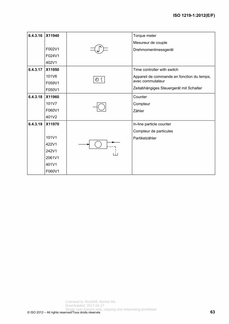
ISO 1219-1:2012(E/F)
© ISO 2012 – All rights reserved/Tous droits réservés 63
6.4.3.16 X11940
F002V1
F024V1
402V1
Torque meter
Mesureur de couple
Drehmomentmessgerät
6.4.3.17 X11950
101V6
F059V1
F050V1
Time controller with switch
Appareil de commande en fonction du temps, avec commutateur
Zeitabhängiges Steuergerät mit Schalter
6.4.3.18 X11960
101V7
F060V1
401V2
Counter
Compteur
Zähler
6.4.3.19 X11970
101V1
422V1
242V1
2061V1
401V1
F060V1
In-line particle counter
Compteur de particules
Partikelzähler
Licensed to: Rockhill, Denise MsDownloaded: 2017-04-17Single user licence only, copying and networking prohibited

ISO 1219-1:2012(E/F)
64 © ISO 2012 – All rights reserved/Tous droits réservés
6.4.4 Filters and separators
Filtres et séparateurs
Filter und Abscheider
Reg. No.
N° d'enreg.
Regist Nr.
Graphic
Graphique
Grafik
Description
Description
Beschreibung
6.4.4.1 X11980
101V15
F061V1
401V2
Filter
Filtre
Filter
6.4.4.2 X11990
101V15
F061V1
244V2
401V2
401V1
Reservoir-breather filter
Filtre d'aération de réservoir
Tank-Belüftungsfilter
6.4.4.3 X12000
101V15
F061V1
326V1
401V2
Filter with additional magnetic element
Filtre avec élément magnétique complémentaire
Filter mit zusätzlichem magnetischen Element
6.4.4.4 X12010
101V15
F061V1
101V6
148V1
F056V1
401V2
401V1
501V1
Filter with optical clogging indicator
Filtre avec indicateur de colmatage optique
Filter mit optischer Verschmutzungsanzeige
Licensed to: Rockhill, Denise MsDownloaded: 2017-04-17Single user licence only, copying and networking prohibited

ISO 1219-1:2012(E/F)
© ISO 2012 – All rights reserved/Tous droits réservés 65
6.4.4.5 X12020
101V15
F061V1
F002V1
148V1
401V2
401V1
501V1
Filter with pressure-measuring instrument
Filtre avec manomètre
Filter mit Druckmessgerät
6.4.4.6 X12030
101V15
F061V1
2031V1
401V1
101V1
401V2
501V1
Filter with a throttled bypass flow
Filtre avec écoulement partiel
Filter mit gedrosseltem Bypass
6.4.4.7 X12040
101V15
F061V1
2002V1
2162V1
2163V1
501V1
401V1
101V1
401V2
Filter with bypass valve
Filtre avec soupape de dérivation
Filter mit Umgehungsventil
Licensed to: Rockhill, Denise MsDownloaded: 2017-04-17Single user licence only, copying and networking prohibited

ISO 1219-1:2012(E/F)
66 © ISO 2012 – All rights reserved/Tous droits réservés
6.4.4.8 X12050
101V15
F061V1
2002V1
2162V1
2163V1
501V1
101V6
148V1
235V1
401V1
101V1
401V2
Filter with bypass valve and digital indicator
Filtre avec soupape de dérivation et indicateur numérique
Filter mit Umgehungsventil und digitaler Anzeige
6.4.4.9 X12060
101V15
F061V1
2002V1
2162V1
2163V1
501V1
101V6
148V1
401V1
101V5
F050V1
F056V1
101V1
401V2
Filter with bypass valve with optical clogging indicator and electrical contact
Filtre avec soupape de dérivation, indicateur optique de colmatage et contact électrique
Filter mit Umgehungsventil mit optischer Verschmutzungsanzeige und Kontaktschalter
Licensed to: Rockhill, Denise MsDownloaded: 2017-04-17Single user licence only, copying and networking prohibited

ISO 1219-1:2012(E/F)
© ISO 2012 – All rights reserved/Tous droits réservés 67
6.4.4.10 X12070
101V15
F061V1
101V6
148V1
F056V1
401V2
401V1
501V1
Filter with optical clogging indicator based on differential pressure
Filtre avec indicateur optique de colmatage basé sur la pression différentielle
Filter mit optischer Verschmutzungsanzeige, auf Differenzdruck basierend
6.4.4.11 X12080
101V15
F061V1
F002V1
148V1
401V2
101V5
F050V1
401V1
501V1
Filter with pressure-measuring instrument and electrical contact
Filtre à manomètre et contact électrique
Filter mit Druckmessgerät und Kontaktschalter
6.4.4.12 X12090
101V15
F066V1
401V2
Centrifugal separator
Séparateur centrifuge
Zentrifugalabscheider
6.4.4.13 X12170
101V15
F037V1
401V1
101V1
401V2
F061V1
Double filter with manual changeover feature
Filtre double à commutation manuelle
Doppelfilter mit manueller Umschaltung
Licensed to: Rockhill, Denise MsDownloaded: 2017-04-17Single user licence only, copying and networking prohibited

ISO 1219-1:2012(E/F)
68 © ISO 2012 – All rights reserved/Tous droits réservés
6.4.5 Heat exchangers
Échangeurs de chaleur
Wärmetauscher
Reg. No.
N° d'enreg.
Regist Nr.
Graphic
Graphique
Grafik
Description
Description
Beschreibung
6.4.5.1 X12260
101V15
F067V1
401V1
401V2
Cooler without indication of the flow paths of the coolant
Refroidisseur sans indication des conduites pour le sens d'écoulement du fluide réfrigérant
Kühler, ohne Volumenstromlinien für die Fließrichtung des Kühlmediums
6.4.5.2 X12270
101V15
F067V1
242V1
401V1
401V2
Cooler with liquid coolant
Refroidisseur avec fluide réfrigérant
Kühler mit flüssigem Kühlmedium
6.4.5.3 X12280
101V15
F067V1
2065V1
F072V1
402V5
401V2
F019V2
401V1
Cooler with electrically powered fan
Refroidisseur avec ventilateur à commande électrique
Kühler mit elektrisch angetriebenem Lüfter
Licensed to: Rockhill, Denise MsDownloaded: 2017-04-17Single user licence only, copying and networking prohibited

ISO 1219-1:2012(E/F)
© ISO 2012 – All rights reserved/Tous droits réservés 69
6.4.5.4 X12290
101V15
F067V1
401V1
401V2
Heater
Réchauffeur
Heizung
6.4.5.5 X12300
101V15
F067V1
401V1
401V2
Temperature regulator
Régulateur de température
Temperaturregler
6.4.6 Energy accumulators (pressure vessels, gas bottles)
Accumulateurs d'énergie (réservoirs sous pression, bouteilles à gaz)
Energiespeicher (Druckbehälter, Gasflaschen)
Reg. No.
N° d'enreg.
Regist Nr.
Graphic
Graphique
Grafik
Description
Description
Beschreibung
6.4.6.1 X12320
F069V1
244V2
401V1
401V2
Gas-loaded accumulator in which the media are separated by a diaphragm (diaphragm-type accumulator)
Accumulateur hydropneumatique dans lequel les fluides sont séparés par une membrane (accumulateur à membrane)
Gasdruckspeicher, Trennung der Medien durch Membran (Membranspeicher)
6.4.6.2 X12330
F069V1
244V2
452V1
401V2
Gas-loaded accumulator in which the media are separated by a bladder (bladder-type accumulator)
Accumulateur hydropneumatique dans lequel les fluides sont séparés par une vessie (accumulateur à vessie)
Gasdruckspeicher, Trennung der Medien durch Blase (Blasenspeicher)
Licensed to: Rockhill, Denise MsDownloaded: 2017-04-17Single user licence only, copying and networking prohibited

ISO 1219-1:2012(E/F)
70 © ISO 2012 – All rights reserved/Tous droits réservés
6.4.6.3 X12340
F069V1
101V14
244V2
401V2
Gas-loaded accumulator in which the media are separated by a piston and piston bladder (piston-type accumulator)
Accumulateur hydropneumatique dans lequel les fluides sont séparés par un piston et vessie (accumulateur à piston)
Gasdruckspeicher, Trennung der Medien durch Kolben und Blase (Kolbenspeicher)
6.4.6.4 X12350
F069V1
244V2
401V2
Gas bottle
Bouteille à gaz
Gasflasche
6.4.6.5 X12360
F069V1
101V14
244V2
401V1
401V2
Piston-type accumulator with back-up bottle
Accumulateur à piston et bouteille à gaz disposée en aval
Kolbenspeicher mit nachgeschalteter Gasflasche
6.4.7 Lubrication points
Points de lubrification
Schmierstellen
Reg. No.
N° d'enreg.
Regist Nr.
Graphic
Graphique
Grafik
Description
Description
Beschreibung
6.4.7.1 X12440
101V21
Lubrication point
Point de lubrification
Schmierstelle
Licensed to: Rockhill, Denise MsDownloaded: 2017-04-17Single user licence only, copying and networking prohibited

ISO 1219-1:2012(E/F)
© ISO 2012 – All rights reserved/Tous droits réservés 71
7 Examples of pneumatic applications
Exemples d'applications pneumatiques
Anwendungsbeispiele Pneumatik
7.1 Valves
Distributeurs
Ventile
7.1.1 Control mechanisms
Mécanismes de commande
Betätigungseinrichtungen
Reg. No.
N° d'enreg.
Regist Nr.
Graphic
Graphique
Grafik
Description
Description
Beschreibung
7.1.1.1 X10010
402V5
655V1
686V1
F041V1
Control mechanism with detachable grip and detent
Commande par poignée amovible, avec dispositif de maintien en position
Betätigung mit abnehmbarem Griff und Raste
7.1.1.2 X10020
402V5
711V1
201V2
Plunger with adjustable stroke limiter
Poussoir à limitation de course variable
Stößel mit einstellbarer Hubbegrenzung
7.1.1.3 X10030
402V5
655V1
684V1
F041V1
Push-pull control mechanism with detent
Commande par poussoir et tirette à crantage
Betätigung durch Drücken und Ziehen mit Raste
Licensed to: Rockhill, Denise MsDownloaded: 2017-04-17Single user licence only, copying and networking prohibited

ISO 1219-1:2012(E/F)
72 © ISO 2012 – All rights reserved/Tous droits réservés
7.1.1.4 X10040
402V2
681V2
F041V1
655V1
Locking control mechanism with manual override
Dispositif de commande auxiliaire manuelle à crantage
Handhilfsbetätigungseinrichtung mit Raste
7.1.1.5 X10050
402V5
685V1
F041V1
655V1
Control mechanism by turning with five detent positions
Commande en tournant à cinq positions de crantage
Betätigung durch Drehen mit fünf Raststellungen
7.1.1.6 X10060
402V5
2005V1
712V1
Roller lever for actuation in one direction of travel
Levier à galet pour commande dans un sens de déplacement
Rollenhebel für Betätigung in einer Verfahrrichtung
7.1.1.7 X10070
F019V2
211V1
402V5
F002V1
Control mechanism using an electric stepping motor
Commande par moteur pas à pas
Betätigung durch Schrittmotor
7.1.1.8 X10080
101V2
244V1
401V1
Pneumatic spring, internal pressure supply using the valve-inlet port
Ressort pneumatique, alimentation interne par orifice de raccordement d’entrée
Luftfeder, intern versorgt über Versorgungsanschluss
Licensed to: Rockhill, Denise MsDownloaded: 2017-04-17Single user licence only, copying and networking prohibited

ISO 1219-1:2012(E/F)
© ISO 2012 – All rights reserved/Tous droits réservés 73
7.1.1.9 X10090
101V2
244V1
422V1
401V1
F035V1
Pneumatic spring, internal pressure supply using the pilot-supply port
NOTE For better understanding, the external pilot supply line is shown.
Ressort pneumatique, alimentation interne par orifice de raccordement auxiliaire de pilotage
NOTE L’orifice de raccordement auxiliaire de pilotage externe est représenté pour une meilleure compréhension.
Luftfeder, intern versorgt über Steuerhilftsluftanschluss
ANMERKUNG Zum besseren Verständnis ist der externe Steuerhilfsluftanschluss dargestellt.
7.1.1.10 X10100
101V2
244V1
401V1
F035V1
Pneumatic spring, external pressure supply
Ressort pneumatique, alimentation par orifice de raccordement externe
Luftfeder, versorgt durch externen Anschluss
7.1.1.11 X10110
101V2
212V1
Solenoid coil with one winding, direction of actuation towards the valving element
Bobine d'électroaimant à un enroulement, agissant vers le composant
Magnetspule mit einer Wicklung, Wirkrichtung zum Verstellelement hin
7.1.1.12 X10120
101V2
212V2
Solenoid coil with one winding, direction of actuation away from the valving element
Bobine d'électroaimant à un enroulement, agissant à partir du composant
Magnetspule mit einer Wicklung, Wirkrichtung vom Verstellelement weg
7.1.1.13 X10130
101V2
212V4
Electrical control mechanism with two coils, one acting towards the valving element and the other acting away from the valving element
Dispositif de commande électrique à deux enroulements, l'un agissant vers le composant, l'autre à partir du composant
Elektrische Betätigungseinrichtung mit zwei Wicklungen; eine wirkt gegen das Ventilelement und die andere wirkt vom Ventilelement weg
Licensed to: Rockhill, Denise MsDownloaded: 2017-04-17Single user licence only, copying and networking prohibited

ISO 1219-1:2012(E/F)
74 © ISO 2012 – All rights reserved/Tous droits réservés
7.1.1.14 X10140
101V2
212V1
201V2
Solenoid coil with one winding, direction of actuation towards the valving element, continuously controlled
Bobine d'électroaimant à un enroulement, agissant vers le composant, réglable en permanence
Magnetspule mit einer Wicklung, Wirkrichtung zum Verstellelement hin, stetig verstellbar
7.1.1.15 X10150
101V2
212V2
201V2
Solenoid coil with one winding, direction of actuation away from the valving element, continuously controlled
Bobine d'électroaimant à un enroulement, agissant à partir du composant, réglable en permanence
Magnetspule mit einer Wicklung, Wirkrichtung vom Verstellelement weg, stetig verstellbar
7.1.1.16 X10160
101V2
212V4
201V2
Electrical control mechanism with two coils, acting in both directions towards and away from the valving element, continuously controlled
Bobine d'électroaimant à deux enroulements, agissant vers le composant et à partir du composant, réglable en permanence
Elektrische Betätigungseinrichtung mit zwei Wicklungen, Wirkrichtung zum Verstellelement hin und vom Verstellelement weg, stetig verstellbar
7.1.1.17 X10170
101V2
212V2
244V1
Electrically operated pneumatic control mechanism
Commande électropneumatique de pilotage
Elektrisch betätigte pneumatische Vorsteuerung
Licensed to: Rockhill, Denise MsDownloaded: 2017-04-17Single user licence only, copying and networking prohibited
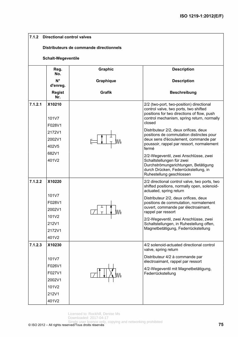
ISO 1219-1:2012(E/F)
© ISO 2012 – All rights reserved/Tous droits réservés 75
7.1.2 Directional control valves
Distributeurs de commande directionnels
Schalt-Wegeventile
Reg. No.
N° d'enreg.
Regist Nr.
Graphic
Graphique
Grafik
Description
Description
Beschreibung
7.1.2.1 X10210
101V7
F028V1
2172V1
2002V1
402V5
682V1
401V2
2/2 (two-port, two-position) directional control valve, two ports, two shifted positions for two directions of flow, push control mechanism, spring return, normally closed
Distributeur 2/2, deux orifices, deux positions de commutation distinctes pour deux sens d'écoulement, commande par poussoir, rappel par ressort, normalement fermé
2/2-Wegeventil, zwei Anschlüsse, zwei Schaltstellungen für zwei Durchströmungsrichtungen, Betätigung durch Drücken, Federrückstellung, in Ruhestellung geschlossen
7.1.2.2 X10220
101V7
F028V1
2002V1
101V2
212V1
2172V1
401V2
2/2 directional control valve, two ports, two shifted positions, normally open, solenoid-actuated, spring return
Distributeur 2/2, deux orifices, deux positions de commutation, normalement ouvert, commande par électroaimant, rappel par ressort
2/2-Wegeventil, zwei Anschlüsse, zwei Schaltstellungen, in Ruhestellung offen, Magnetbetätigung, Federrückstellung
7.1.2.3 X10230
101V7
F026V1
F027V1
2002V1
101V2
212V1
401V2
4/2 solenoid-actuated directional control valve, spring return
Distributeur 4/2 à commande par électroaimant, rappel par ressort
4/2-Wegeventil mit Magnetbetätigung, Federrückstellung
Licensed to: Rockhill, Denise MsDownloaded: 2017-04-17Single user licence only, copying and networking prohibited

ISO 1219-1:2012(E/F)
76 © ISO 2012 – All rights reserved/Tous droits réservés
7.1.2.4 X10240
101V7
F026V1
F021V1
401V2
101V2
212V1
2002V1
244V1
Pneumatic soft-start valve, solenoid-operated, with internal pilot supply
Soupape pneumatique de démarrage progressif, commande électrique, avec alimentation par pilote interne
Pneumatisches Anfahrventil, elektrisch betätigt mit interner Steuerdruckversorgung
7.1.2.5 X10250
101V1
101V7
2172V1
F026V1
101V2
244V1
2031V1
201V4
501V1
2002V1
422V1
Pneumatic slow-start valve that is fitted at the inlet to a system, which allows fluid to enter the system at a reduced flow rate, until a pre-set pressure level is achieved, causing the valve to open to a full-flow condition
Soupape pneumatique de démarrage progressif, pourvue à l'entrée d'un système autorisant l'entrée du fluide à un débit réduit jusqu'au niveau de pression de réglage, entraînant l'ouverture de la soupape pour un débit maximal
Pneumatisches Druckaufbau- /Anfahrventil, das am Eingang eines Systems angeordnet wird und den Zustrom eines verringerten Volumenstroms ermöglicht, bis ein voreingestellter Druck erreicht ist, bei dem das Ventil öffnet und den vollen Volumenstrom durchlässt
7.1.2.6 X10260
101V7
F026V1
F027V1
2172V1
402V5
682V1
F039V1
401V2
3/2 lockout valve with padlock
Distributeur 3/2 à commande verrouillable avec cadenas
3/2-Wegeventil mit abschließbarer Betätigung mit Vorhängeschloss
Licensed to: Rockhill, Denise MsDownloaded: 2017-04-17Single user licence only, copying and networking prohibited

ISO 1219-1:2012(E/F)
© ISO 2012 – All rights reserved/Tous droits réservés 77
7.1.2.7 X10270
101V7
F026V1
F027V1
2172V1
2002V1
712V1
2005V1
402V5
401V2
3/2 directional control valve controlled by a roller lever and spring return
Distributeur 3/2, commande par levier à galet, rappel par ressort
3/2-Wegeventil, betätigt durch Rollenhebel, Federrückstellung
7.1.2.8 X10280
101V7
F026V1
F027V1
2172V1
2002V1
101V2
212V1
401V2
3/2 directional control valve, with three ports and two distinct positions (normally closed), controlled by a solenoid and spring return
Distributeur 3/2 avec trois orifices et deux positions de commutation (normalement fermé), commande par électroaimant, rappel par ressort
3/2-Wegeventil mit drei Anschlüssen und zwei Schaltstellungen (Ruhestellung geschlossen), Betätigung durch Magnet, Federrückstellung
7.1.2.9 X10290
101V7
F026V1
F027V1
2172V1
2002V1
101V2
212V1
681V2
402V2
655V1
F041V1
401V2
3/2 directional control valve with single solenoid, directly controlled, spring return, and manual override with detent
Distributeur 3/2 avec un électroaimant, commande directe, rappel par ressort, et commande auxiliaire manuelle par dispositif de maintien en position
3/2-Wegeventil mit einem Magnet, direkt betätigt, Federrückstellung und Hilfsbetätigungseinrichtung mit Raste
Licensed to: Rockhill, Denise MsDownloaded: 2017-04-17Single user licence only, copying and networking prohibited

ISO 1219-1:2012(E/F)
78 © ISO 2012 – All rights reserved/Tous droits réservés
7.1.2.10 X10300
101V7
F026V1
F027V1
2172V1
2002V1
401V2
402V2
F060V1
244V1
Pulse counter with pneumatic output signal
Compteur d'impulsions à signal de sortie pneumatique
Pneumatischer Pulszähler mit pneumatischem Ausgangssignal
7.1.2.11 X10310
101V7
F026V1
F027V1
2172V1
2177V1
244V1
401V1
401V2
3/2 directional control valve, differential pilot
Distributeur 3/2, pilotage différentiel
3/2-Wegeventil, unterschiedlich große Steuerflächen
7.1.2.12 X10320
101V7
101V2
F026V1
F027V1
2002V1
212V1
401V2
402V2
655V1
681V2
F041V1
4/2 directional control valve with single solenoid, directly controlled, spring return, and manual override with detent
Distributeur 4/2 à commande directe par électroaimant, rappel par ressort, commande auxiliaire manuelle par dispositif de maintien en position
4/2-Wegeventil mit einem Magnet, direkt betätigt, Federrückstellung und Hilfsbetätigungseinrichtung mit Raste
Licensed to: Rockhill, Denise MsDownloaded: 2017-04-17Single user licence only, copying and networking prohibited

ISO 1219-1:2012(E/F)
© ISO 2012 – All rights reserved/Tous droits réservés 79
7.1.2.13 X10330
101V7
F026V1
F027V1
101V2
212V1
655V1
F041V1
401V2
4/2 directional control valve, directly controlled by two solenoids, with detent (impulse valve)
Distributeur 4/2 à commande directe par deux électroaimants, avec dispositif de maintien en position (distributeur d'impulsion)
4/2-Wegeventil mit direkter Betätigung durch zwei Magnete, mit Raste (Impulsventil)
7.1.2.14 X10340
101V7
F026V1
F027V1
2172V1
101V2
244V1
F042V1
2002V1
401V2
3/2 directional control valve with three ports, two distinct positions, controlled by pneumatic pilot control and torsion bar, spring return
Distributeur 3/2 avec trois orifices de raccordement, deux positions de commutation, commande par pilotage pneumatique et barre de torsion, rappel par ressort
3/2-Wegeventil mit drei Anschlüssen, zwei Schaltstellungen, Betätigung durch pneumatische Vorsteuerung und Federstab, Federrückstellung
7.1.2.15 X10370
101V7
F026V1
F027V1
2172V1
2002V1
101V2
212V1
F034V1
F031V1
501V2
401V2
4/3 directional control valve, directly controlled by two solenoids with spring-centred central position
Distributeur 4/3 à commande directe par deux électroaimants, centrage par ressort de la position médiane
4/3-Wegeventil mit direkter Betätigung durch zwei Magnete, Federzentrierung der Mittelstellung
Licensed to: Rockhill, Denise MsDownloaded: 2017-04-17Single user licence only, copying and networking prohibited
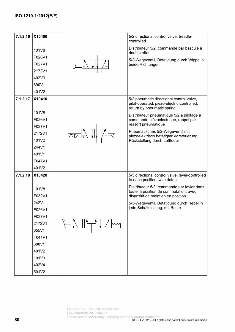
ISO 1219-1:2012(E/F)
80 © ISO 2012 – All rights reserved/Tous droits réservés
7.1.2.16 X10400
101V8
F026V1
F027V1
2172V1
402V3
690V1
401V2
5/2 directional control valve, treadle-controlled
Distributeur 5/2, commande par bascule à double effet
5/2-Wegeventil, Betätigung durch Wippe in beide Richtungen
7.1.2.17 X10410
101V8
F026V1
F027V1
2172V1
101V2
244V1
401V1
F047V1
401V2
5/2 pneumatic directional control valve, pilot-operated, piezo-electric-controlled, return by pneumatic spring
Distributeur pneumatique 5/2 à pilotage à commande piézoélectrique, rappel par ressort pneumatique
Pneumatisches 5/2-Wegeventil mit piezoelektrisch betätigter Vorsteuerung, Rückstellung durch Luftfeder
7.1.2.18 X10420
101V8
F032V1
242V1
F026V1
F027V1
2172V1
655V1
F041V1
688V1
401V2
101V3
402V4
501V2
5/3 directional control valve, lever-controlled to each position, with detent
Distributeur 5/3, commande par levier dans toute la position de commutation, avec dispositif de maintien en position
5/3-Wegeventil, Betätigung durch Hebel in jede Schaltstellung, mit Raste
Licensed to: Rockhill, Denise MsDownloaded: 2017-04-17Single user licence only, copying and networking prohibited
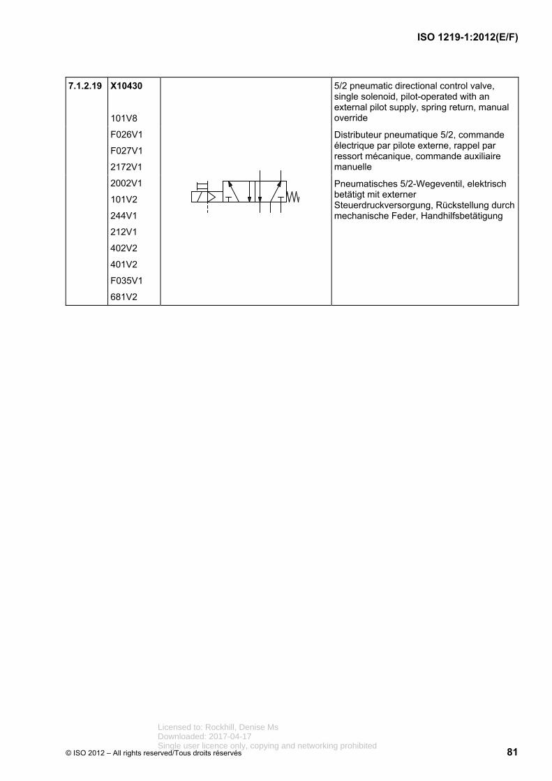
ISO 1219-1:2012(E/F)
© ISO 2012 – All rights reserved/Tous droits réservés 81
7.1.2.19 X10430
101V8
F026V1
F027V1
2172V1
2002V1
101V2
244V1
212V1
402V2
401V2
F035V1
681V2
5/2 pneumatic directional control valve, single solenoid, pilot-operated with an external pilot supply, spring return, manual override
Distributeur pneumatique 5/2, commande électrique par pilote externe, rappel par ressort mécanique, commande auxiliaire manuelle
Pneumatisches 5/2-Wegeventil, elektrisch betätigt mit externer Steuerdruckversorgung, Rückstellung durch mechanische Feder, Handhilfsbetätigung
Licensed to: Rockhill, Denise MsDownloaded: 2017-04-17Single user licence only, copying and networking prohibited

ISO 1219-1:2012(E/F)
82 © ISO 2012 – All rights reserved/Tous droits réservés
7.1.2.20 X10440
X10441
X10442
101V8
F026V1
F027V1
2172V1
101V2
244V1
212V1
681V2
401V1
401V2
422V1
402V2
F035V1
RF011
5/2 pneumatic directional control valve with five ports and two distinct positions, control by solenoid and pneumatic pilot control, with external pilot supply, return by pneumatic spring, auxiliary manual control
The different possibilities for pressure supply to the pneumatic spring are shown:
internal pressure supply using the valve supply port (X10440),
internal pressure supply using the pilot supply port (X10441),
external pressure supply (X10442).
Distributeur pneumatique 5/2 à cinq orifices de raccordement et deux positions de commutation, commande par électroaimant et pilotage pneumatique, alimentation externe d'air de pilotage, rappel par ressort pneumatique, commande manuelle auxiliaire.
Les différentes possibilités d'alimentation en pression des ressorts pneumatiques sont représentées:
alimentation en interne par orifice d'alimentation (X10440),
alimentation en interne par orifice d'air de pilotage auxiliaire (X10441),
alimentation par orifice externe (X10442).
Pneumatisches 5/2-Wegeventil mit fünf Anschlüssen und zwei Schaltstellungen, Betätigung durch Magnet und pneumatische Vorsteuerung, mit externer Vorsteuerluftversorgung, Rückstellung durch Luftfeder, Handhilfsbetätigung
Verschiedene Möglichkeiten der Druckversorgung der Luftfeder sind dargestellt,
intern versorgt über Versorgungsan-schluss (X10440),
intern versorgt über Steuerhilftsluftan-schluss (X10441),
versorgt durch externen Anschluss (X10442).
Licensed to: Rockhill, Denise MsDownloaded: 2017-04-17Single user licence only, copying and networking prohibited

ISO 1219-1:2012(E/F)
© ISO 2012 – All rights reserved/Tous droits réservés 83
7.1.2.21 X10450
101V8
F028V1
F029V1
2172V1
101V2
244V1
2002V1
402V2
681V2
401V2
212V1
5/3 pneumatic directional control valve, closed centre position, controlled by solenoid pilots with internal pilot supply and manual overrides on both sides. Spring return to the centre position
Distributeur pneumatique 5/3, à position médiane fermée, commande par électroaimant des deux côtés, avec alimentation par pilote interne et commande auxiliaire manuelle. Position médiane à centrage par ressort.
Pneumatisches 5/3-Wegeventil, Ruhestellung gesperrt mit fünf Anschlüssen, drei Schaltstellungen, Betätigung durch beidseitige Magnete mit einer Wicklung und pneumatischer Vorsteuerung. Mittelstellung federzentriert, beidseitige Handhilfsbetätigung, nicht rastend
7.1.2.22 X10460
101V8
F026V1
F027V1
2172V1
101V2
2002V1
401V1
401V2
244V1
422V1
Directly operated 5/2 pneumatic directional control valve, mechanical spring and air spring returned
Distributeur pneumatique 5/2, à commande directe, rappel par ressort mécanique et ressort pneumatique
Direkt betätigtes pneumatisches 5/2-Wegeventil mit Rückstellung durch mechanische Feder und Luftfeder
7.1.2.23 X10470
101V8
F026V1
F027V1
2172V1
2002V1
401V2
244V1
422V1
Directly operated 5/3 pneumatic directional control valve, spring centred, with outlet ports open to exhaust in the centre position
Distributeur pneumatique 5/3, à commande directe, centrage par ressort, ouvert en position médiane
Direkt betätigtes pneumatisches 5/3-Wegeventil mit Federzentrierung, in Mittelstellung geöffnet
Licensed to: Rockhill, Denise MsDownloaded: 2017-04-17Single user licence only, copying and networking prohibited

ISO 1219-1:2012(E/F)
84 © ISO 2012 – All rights reserved/Tous droits réservés
7.1.3 Pressure control valves
Distributeurs de commande de pression
Schalt-Druckventile
Reg. No.
N° d'enreg.
Regist Nr.
Graphic
Graphique
Grafik
Description
Description
Beschreibung
7.1.3.1 X10500
101V7
F026V1
2002V1
201V2
422V2
401V2
Directly controlled pressure-relief valve, in which the opening pressure may be adjusted by means of a spring
Limiteur de pression à action directe, la pression d'ouverture étant réglable par ressort
Direktgesteuertes Druckbegrenzungsventil, der Öffnungsdruck ist über Feder einstellbar
7.1.3.2 X10530
101V7
F026V1
2002V1
201V2
244V1
422V1
401V2
Sequence valve, externally controlled
Soupape de priorité à commande externe
Folgeventil, extern gesteuert
7.1.3.3 X10540
101V7
F028V1
2002V1
201V2
422V4
2174V1
401V2
Pressure regulator, with internal reversible flow
Régulateur de pression, à écoulement interne réversible
Druckreduzierventil, mit internem reversiblem Volumenstrom
Licensed to: Rockhill, Denise MsDownloaded: 2017-04-17Single user licence only, copying and networking prohibited

ISO 1219-1:2012(E/F)
© ISO 2012 – All rights reserved/Tous droits réservés 85
7.1.3.4 X10570
101V7
F026V1
101V2
244V1
422V4
401V2
2174V1
F035V1
Pressure regulator, remote pilot adjusted, relieving, forward flow only
Régulateur de pression, commande à distance, écoulement dans un sens
Druckreduzierventil, ferngesteuert, Durchfluss in einer Richtung
7.1.3.5 X10620
101V16
F040V1
401V1
401V2
Dual pressure valve (AND function), in which an output signal is only obtained when both inlets are under pressure. The weaker signal is fed to the output.
Distributeur à deux pressions (fonction ET), dans lequel un signal de sortie est émis lorsque les deux orifices d'entrée sont soumis à la pression. Le signal le plus faible apparaît à la sortie.
Zweidruckventil (UND – Funktion), ein Ausgangssignal ist dann gegeben, wenn beide Eingänge unter Druck stehen. Das schwächere Signal erscheint am Ausgang.
Licensed to: Rockhill, Denise MsDownloaded: 2017-04-17Single user licence only, copying and networking prohibited

ISO 1219-1:2012(E/F)
86 © ISO 2012 – All rights reserved/Tous droits réservés
7.1.4 Flow control valves
Distributeurs de commande de débit
Schalt-Stromventile
Reg. No.
N° d'enreg.
Regist Nr.
Graphic
Graphique
Grafik
Description
Description
Beschreibung
7.1.4.1 X10630
401V1
2031V1
201V4
Flow control valve, adjustable
Gicleur réglable
Drosselventil, einstellbar
7.1.4.2 X10640
401V1
2031V1
201V4
2162V1
2163V1
501V1
101V1
401V2
Flow control valve, adjustable, with reverse free flow
Gicleur avec clapet, réglable, écoulement libre dans un sens
Drossel-Rückschlagventil, einstellbar, freier Durchfluss in einer Richtung
7.1.4.3 X10650
101V7
F028V1
2172V1
RF028
2002V1
402V5
712V1
401V2
Flow control valve, operated by roller plunger, spring returned
Limiteur de débit réglable, commande mécanique par galet, rappel par ressort
Verstellbares Drosselventil, Betätigung mittels Rollenstößel, Federrückstellung
Licensed to: Rockhill, Denise MsDownloaded: 2017-04-17Single user licence only, copying and networking prohibited

ISO 1219-1:2012(E/F)
© ISO 2012 – All rights reserved/Tous droits réservés 87
7.1.5 Non-return (check) valves and shuttle valves
Clapets antiretour et sélecteurs de circuit
Rückschlagventile und Wechselventile
Reg. No.
N° d'enreg.
Regist Nr.
Graphic
Graphique
Grafik
Description
Description
Beschreibung
7.1.5.1 X10700
2162V1
2163V1
401V1
Non-return valve, free flow only possible in one direction
Clapet antiretour, écoulement possible dans un seul sens
Rückschlagventil, Durchfluss nur in einer Richtung möglich
7.1.5.2 X10710
2162V1
2163V1
401V1
2002V1
Non-return valve with spring, free flow only possible in one direction, normally closed
Clapet antiretour à ressort, écoulement possible dans un seul sens, normalement fermé
Rückschlagventil mit Feder, Durchfluss nur in einer Richtung möglich, Ruhestellung geschlossen
7.1.5.3 X10720
2162V1
2163V1
401V1
422V1
2002V1
101V1
401V2
F035V1
Pilot-operated non-return valve with spring, pilot pressure allows free flow in both directions
Clapet antiretour à déverrouillage à ressort, écoulement possible dans les deux sens par pression de pilotage
Entsperrbares Rückschlagventil mit Feder, durch Steuerdruck Durchfluss in beiden Richtungen möglich
Licensed to: Rockhill, Denise MsDownloaded: 2017-04-17Single user licence only, copying and networking prohibited

ISO 1219-1:2012(E/F)
88 © ISO 2012 – All rights reserved/Tous droits réservés
7.1.5.4 X10730
101V1
2162V1
2163V1
422V1
401V1
501V1
401V2
Double non-return valve, pilot-operated
Clapet antiretour double, déverrouillable
Doppelrückschlagventil, entsperrbar
7.1.5.5 X10740
101V16
2162V1
2163V1
501V2
401V1
401V2
Shuttle valve (OR function), in which the inlet to which the higher pressure is applied is automatically connected to the outlet
Sélecteur de circuit (fonction OU), dans lequel l'entrée sur laquelle s'applique la pression la plus élevée est reliée automatiquement à la sortie
Wechselventil (ODER-Funktion), der Eingang, an dem der höhere Druck anliegt, wird automatisch mit dem Ausgang verbunden
7.1.5.6 X10750
2031V1
101V16
2162V1
2163V1
501V2
401V1
401V2
Quick-exhaust valve
Soupape d'échappement rapide
Schnell-Entlüftungsventil
Licensed to: Rockhill, Denise MsDownloaded: 2017-04-17Single user licence only, copying and networking prohibited

ISO 1219-1:2012(E/F)
© ISO 2012 – All rights reserved/Tous droits réservés 89
7.1.6 Proportional directional control valves
Distributeurs proportionnels de commande directe
Stetig-Wegeventile
Reg. No.
N° d'enreg.
Regist Nr.
Graphic
Graphique
Grafik
Description
Description
Beschreibung
7.1.6.1 X10760
101V7
F026V1
F027V1
2172V1
RF028
101V2
212V1
201V2
2002V1
RF011
401V2
RF011
401V2
Proportional directional control valve, directly controlled
Distributeur proportionnel, à commande directe
Proportional-Wegeventil, direkt betätigt
Licensed to: Rockhill, Denise MsDownloaded: 2017-04-17Single user licence only, copying and networking prohibited

ISO 1219-1:2012(E/F)
90 © ISO 2012 – All rights reserved/Tous droits réservés
7.1.7 Proportional pressure control valves
Distributeurs proportionnels de commande de pression
Stetig-Druckventile
Reg. No.
N° d'enreg.
Regist Nr.
Graphic
Graphique
Grafik
Description
Description
Beschreibung
7.1.7.1 X10830
101V7
F026V1
422V2
2002V1
101V2
212V1
201V2
401V2
Proportional pressure-relief valve, directly controlled, in which the solenoid controls the valve poppet by means of a spring
Limiteur de pression proportionnel, à commande directe, dans lequel l'électroaimant agit sur le ressort du clapet de valve
Proportional-Druckbegrenzungsventil, direkt betätigt, Magnet wirkt über Feder auf Ventilkegel
7.1.7.2 X10840
101V7
F026V1
422V2
101V2
212V1
201V2
401V2
101V5
F052V1
Proportional pressure-relief valve, directly controlled by a solenoid acting on a valve poppet, with integral electronics
Limiteur de pression proportionnel, à commande directe, l'électroaimant agissant sur le clapet du distributeur, électronique intégrée
Proportional-Druckbegrenzungsventil, direkt betätigt, Magnet wirkt auf Ventilkegel, mit integrierter Elektronik
Licensed to: Rockhill, Denise MsDownloaded: 2017-04-17Single user licence only, copying and networking prohibited

ISO 1219-1:2012(E/F)
© ISO 2012 – All rights reserved/Tous droits réservés 91
7.1.7.3 X10850
101V7
F026V1
422V2
2002V1
101V2
212V1
201V2
101V5
F052V1
753V1
F045V1
234V1
401V2
F046V1
Proportional pressure-relief valve, directly controlled, with closed loop position control of the solenoid and with integral electronics
Limiteur de pression proportionnel, piloté à commande directe, avec régulation de la position de l'électroaimant, électronique intégrée
Proportional-Druckbegrenzungsventil, direkt betätigt, mit Lageregelung des Magneten und mit integrierter Elektronik
Licensed to: Rockhill, Denise MsDownloaded: 2017-04-17Single user licence only, copying and networking prohibited

ISO 1219-1:2012(E/F)
92 © ISO 2012 – All rights reserved/Tous droits réservés
7.1.8 Proportional flow control valves
Distributeurs proportionnels de commande de débit
Stetig-Stromventile
Reg. No.
N° d'enreg.
Regist Nr.
Graphic
Graphique
Grafik
Description
Description
Beschreibung
7.1.8.1 X10890
101V7
F028V1
2172V1
RF028
2002V1
101V2
212V1
201V2
401V2
Proportional flow control valve, directly controlled
Vanne de débit proportionnelle à commande directe
Proportional-Stromventil, direkt betätigt.
7.1.8.2 X10900
101V7
F027V1
2172V1
RF028
2002V1
101V2
212V1
201V2
101V5
F052V1
753V1
F045V1
234V1
401V2
RF011
F046V1
Proportional flow control valve, directly controlled, with closed loop position control of the solenoid and integrated electronics
Vanne de débit proportionnelle à commande directe, avec régulation de la position de l'électroaimant, électronique intégrée
Proportional-Stromventil, direkt betätigt, mit Lageregelung des Magneten und integrierter Elektronik
Licensed to: Rockhill, Denise MsDownloaded: 2017-04-17Single user licence only, copying and networking prohibited

ISO 1219-1:2012(E/F)
© ISO 2012 – All rights reserved/Tous droits réservés 93
7.2 Air compressors and motors
Compresseurs et moteurs
Kompressoren und Motore
Reg. No.
N° d'enreg.
Regist Nr.
Graphic
Graphique
Grafik
Description
Description
Beschreibung
7.2.1 X11280
F003V1
256V1
F017V1
401V2
Rotary actuator/swivel drive with a limited swivel angle and two directions of flow
Actionneur à angle de pivotement limité et deux sens d'écoulement
Drehantrieb/Schwenkantrieb mit begrenztem Schwenkwinkel und zwei Volumenstromrichtungen
7.2.2 X11290
F003V1
256V1
F017V1
401V2
2002V1
Semi-rotary actuator/swivel drive, single acting
Actionneur simple effet à angle de pivotement limité
Schwenkantrieb einfachwirkend, mit begrenztem Schwenkwinkel
7.2.3 X11390
2065V1
244V1
F017V1
401V2
Motor
Moteur
Motor
7.2.4 X11400
2065V1
244V1
F017V1
401V2
Compressor
Compresseur
Kompressor
Licensed to: Rockhill, Denise MsDownloaded: 2017-04-17Single user licence only, copying and networking prohibited

ISO 1219-1:2012(E/F)
94 © ISO 2012 – All rights reserved/Tous droits réservés
7.2.5 X11410
2065V1
244V1
F017V1
401V2
256V1
Motor with alternate directions of flow, fixed displacement and two directions of rotation
Moteur à sens d'écoulement alternés, cylindrée fixe et deux sens de rotation
Motor mit wechselnder Volumenstromrichtung, konstantem Schluckvolumen und zwei Drehrichtungen
7.2.6 X11420
2065V1
F017V1
401V2
F023V1
Vacuum pump
Pompe à vide
Vakuumpumpe
7.2.7 X11430
2065V1
243V2
244V2
401V2
Pressure intensifier, continuous, that converts a pneumatic pressure p1 into a higher hydraulic pressure p2
Multiplicateur de pression, à effet continu, qui sert à convertir une pression pneumatique p1 en une pression hydraulique p2 de valeur supérieure
Druckübersetzer, kontinuierlich, der einen pneumatischen Druck p1 in einen höheren hydraulischen Druck p2 umwandelt
7.3 Cylinders
Vérins
Zylinder
Reg. No.
N° d'enreg.
Regist Nr.
Graphic
Graphique
Grafik
Description
Description
Beschreibung
7.3.1 X11440
101V13
2002V3
101V14
F004V1
401V2
Single-acting, single rod cylinder, return stroke by spring force, spring chamber with connection
Vérin simple effet, à simple tige, rappel par ressort avec retour de fuite côté ressort
Einfachwirkender Zylinder, mit einseitiger Kolbenstange, Rückhub durch Federkraft, Federraum mit Anschluss
Licensed to: Rockhill, Denise MsDownloaded: 2017-04-17Single user licence only, copying and networking prohibited
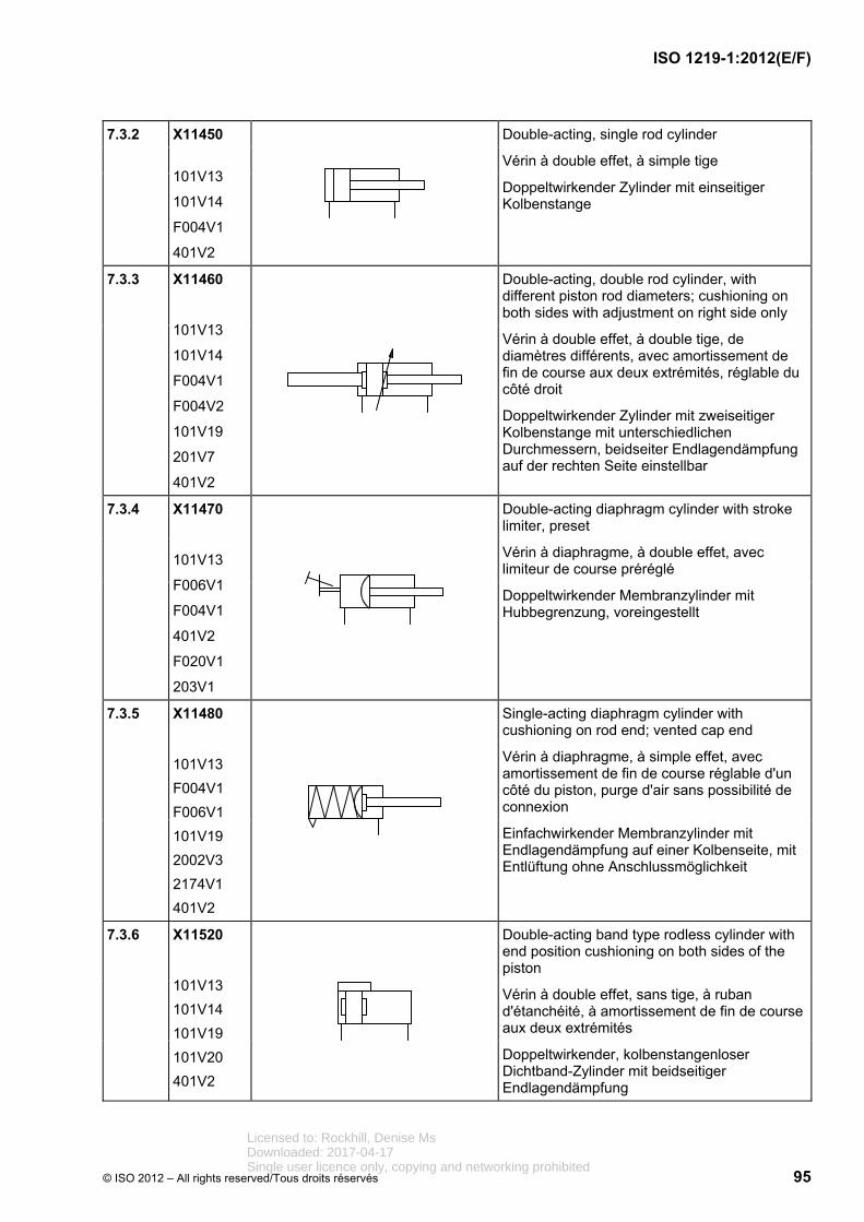
ISO 1219-1:2012(E/F)
© ISO 2012 – All rights reserved/Tous droits réservés 95
7.3.2 X11450
101V13
101V14
F004V1
401V2
Double-acting, single rod cylinder
Vérin à double effet, à simple tige
Doppeltwirkender Zylinder mit einseitiger Kolbenstange
7.3.3 X11460
101V13
101V14
F004V1
F004V2
101V19
201V7
401V2
Double-acting, double rod cylinder, with different piston rod diameters; cushioning on both sides with adjustment on right side only
Vérin à double effet, à double tige, de diamètres différents, avec amortissement de fin de course aux deux extrémités, réglable du côté droit
Doppeltwirkender Zylinder mit zweiseitiger Kolbenstange mit unterschiedlichen Durchmessern, beidseiter Endlagendämpfung auf der rechten Seite einstellbar
7.3.4 X11470
101V13
F006V1
F004V1
401V2
F020V1
203V1
Double-acting diaphragm cylinder with stroke limiter, preset
Vérin à diaphragme, à double effet, avec limiteur de course préréglé
Doppeltwirkender Membranzylinder mit Hubbegrenzung, voreingestellt
7.3.5 X11480
101V13
F004V1
F006V1
101V19
2002V3
2174V1
401V2
Single-acting diaphragm cylinder with cushioning on rod end; vented cap end
Vérin à diaphragme, à simple effet, avec amortissement de fin de course réglable d'un côté du piston, purge d'air sans possibilité de connexion
Einfachwirkender Membranzylinder mit Endlagendämpfung auf einer Kolbenseite, mit Entlüftung ohne Anschlussmöglichkeit
7.3.6 X11520
101V13
101V14
101V19
101V20
401V2
Double-acting band type rodless cylinder with end position cushioning on both sides of the piston
Vérin à double effet, sans tige, à ruban d'étanchéité, à amortissement de fin de course aux deux extrémités
Doppeltwirkender, kolbenstangenloser Dichtband-Zylinder mit beidseitiger Endlagendämpfung
Licensed to: Rockhill, Denise MsDownloaded: 2017-04-17Single user licence only, copying and networking prohibited

ISO 1219-1:2012(E/F)
96 © ISO 2012 – All rights reserved/Tous droits réservés
7.3.7 X11530
101V13
101V14
101V19
101V20
201V7
245V1
401V2
Double-acting cable-type rodless cylinder with adjustable end position cushioning on both sides of the piston
Vérin double effet, sans tige, à ruban/câble, à amortissement de fin de course réglable aux deux extrémités
Doppeltwirkender kolbenstangenloser Zylinder, Seil-/Bandausführung, mit einstellbarer Endlagendämpfung auf beiden Seiten
7.3.8 X11540
101V13
101V14
753V1
F045V1
F048V1
326V1
401V2
F046V1
Double-acting magnetic-type rodless cylinder with position switch on right-hand end only
Vérin à double effet, sans tige, à entraînement magnétique et commutateur de position uniquement à l'extrémité droite
Doppeltwirkender kolbenstangenloser Zylinder, magnetisch gekoppelt, Endschalter nur auf der rechten Seite
7.3.9 X11550
101V13
101V14
F004V1
655V1
F041V1
401V2
F046V1
401V1
Double-acting cylinder with detents at both ends of the stroke
Vérin à double effet avec dispositif de maintien en position aux deux extrémités de la course
Doppeltwirkender Zylinder mit Raste auf beiden Seiten des Hubs
Licensed to: Rockhill, Denise MsDownloaded: 2017-04-17Single user licence only, copying and networking prohibited

ISO 1219-1:2012(E/F)
© ISO 2012 – All rights reserved/Tous droits réservés 97
7.3.10 X11560
101V13
101V14
F004V1
753V1
F045V1
F048V1
401V2
F046V1
401V1
Double-acting cylinder, double rod, with internal limit switch on the left end, external limit switch on the right end, tripped by the piston rod
Vérin à double effet, à double tige, avec interrupteur de fin de course côté gauche, à commande mécanique interne, interrupteur de fin de course externe côté droit, à déclenchement par la tige
Doppeltwirkender Zylinder mit Endschalter auf der linken Seite, intern mechanisch betätigt, externer Endschalter auf der rechten Seite, ausgelöst durch die Kolbenstange
7.3.11 X11570
101V13
101V14
F004V1
661V1
101V2
244V1
401V1
401V2
Double-acting cylinder, mechanism for locking the piston rod and unlocking by pressurization
Vérin à double effet, verrouillage du piston et déverrouillage par application de pression
Doppeltwirkender Zylinder, Vorrichtung zum Blockieren des Kolbens und Lösen durch Druckbeaufschlagung
7.3.12 X11580
101V13
101V14
243V2
244V2
401V2
Pressure medium converter, single-acting, which converts a pneumatic pressure into a hydraulic pressure of the same value, or vice versa
Échangeur de pression air-huile, simple effet, qui sert à convertir une pression pneumatique en pression hydraulique de même valeur, ou inversement
Druckmittelwandler, einfachwirkend, der einen pneumatischen in einen hydraulischen Druck gleicher Höhe umwandelt, oder umgekehrt
7.3.13 X11590
F007V1
F008V1
243V2
244V2
401V2
Pressure intensifier, single-acting, which converts a pneumatic pressure p1 into a higher hydraulic pressure p2
Multiplicateur de pression, simple effet, qui sert à convertir une pression pneumatique p1 en une pression hydraulique p2 de valeur supérieure
Druckübersetzer, einfachwirkend, der einen pneumatischen Druck p1 in einen höheren hydraulischen Druck p2 umwandelt
Licensed to: Rockhill, Denise MsDownloaded: 2017-04-17Single user licence only, copying and networking prohibited

ISO 1219-1:2012(E/F)
98 © ISO 2012 – All rights reserved/Tous droits réservés
7.3.14 X11600
F069V1
RF047
401V2
Bellows cylinder
Actionneur à soufflets
Balgzylinder
7.3.15 X11610
F069V1
RF047
401V2
Hose cylinder
Vérin flexible
Schlauchzylinder
7.3.16 X11620
101V13
101V14
F004V1
326V1
F003V1
256V1
F017V1
401V1
401V2
Semi-rotary linear drive, double-acting with permanent magnet on the piston
Entraînement linéaire pivotant, à double effet, avec aimant permanent sur le piston
Schwenk-Linearantrieb, doppeltwirkend mit Permanentmagnet am Kolben
7.3.17 X11630
101V17
101V14
F009V1
326V1
401V2
Gripper, double-acting with permanent magnet on piston
Grappin en position ouverte, à double effet, avec aimant permanent sur le piston
Greifer, doppeltwirkend, mit Permanentmagnet am Kolben
7.3.18 X11640
101V17
101V14
F009V2
326V1
401V2
Gripper, double-acting with permanent magnet on piston
Grappin en position fermée, à double effet, avec aimant permanent sur le piston
Greifer, doppeltwirkend, mit Permanentmagnet am Kolben
Licensed to: Rockhill, Denise MsDownloaded: 2017-04-17Single user licence only, copying and networking prohibited

ISO 1219-1:2012(E/F)
© ISO 2012 – All rights reserved/Tous droits réservés 99
7.3.19 X11650
101V17
101V14
F009V1
326V1
2002V4
401V2
Gripper, single-acting with permanent magnet on piston
Grappin en position ouverte, à simple effet, avec aimant permanent sur le piston
Greifer, einfachwirkend, mit Permanentmagnet am Kolben
7.3.20 X11660
101V17
101V14
F009V2
326V1
2002V4
401V2
Gripper, single-acting with permanent magnet on piston
Grappin en position fermée, à simple effet, avec aimant permanent sur le piston
Greifer, einfachwirkend, mit Permanentmagnet am Kolben
7.4 Accessories
Accessoires
Zubehör
7.4.1 Connections and joints
Connexions et raccordements
Verbindungen und Anschlüsse
Reg. No.
N° d'enreg.
Regist Nr.
Graphic
Graphique
Grafik
Description
Description
Beschreibung
7.4.1.1 X11670
501V1
452V1
Hose assembly
Conduite flexible
Schlauchleitung
7.4.1.2 X11680
F036V1
RF004
Three-way rotary connection
Connexion tournante à trois voies
Dreiwege-Drehverbindung
Licensed to: Rockhill, Denise MsDownloaded: 2017-04-17Single user licence only, copying and networking prohibited

ISO 1219-1:2012(E/F)
100 © ISO 2012 – All rights reserved/Tous droits réservés
7.4.1.3 X11690
2162V1
2172V1
Quick-action coupling without non-return valve, uncoupled
Raccord rapide sans clapet antiretour, désaccouplé
Schnelltrennkupplung ohne Rückschlagventil, entkuppelt
7.4.1.4 X11700
2162V1
2163V1
2172V1
Quick-action coupling with non-return valve, uncoupled
Raccord rapide avec clapet antiretour, désaccouplé
Schnelltrennkupplung mit Rückschlagventil, entkuppelt
7.4.1.5 X11710
2162V1
2163V1
2172V1
Quick-action coupling with two non-return valves, uncoupled
Raccord rapide avec deux clapets antiretour, désaccouplé
Schnelltrennkupplung mit zwei Rückschlagventilen, entkuppelt
7.4.1.6 X11720
2162V1
2172V1
Quick-action coupling without non-return valve, coupled
Raccord rapide sans clapet antiretour, accouplé
Schnelltrennkupplung ohne Rückschlagventil, gekuppelt
7.4.1.7 X11730
2162V1
2163V1
2172V1
Quick-action coupling with one non-return valve, coupled
Raccord rapide avec un clapet antiretour, accouplé
Schnelltrennkupplung mit einem Rückschlagventil, gekuppelt
7.4.1.8 X11740
2162V1
2163V1
2172V1
Quick-action coupling with two non-return valves, coupled
Raccord rapide avec deux clapets antiretour, accouplé
Schnelltrennkupplung mit zwei Rückschlagventilen, gekuppelt
Licensed to: Rockhill, Denise MsDownloaded: 2017-04-17Single user licence only, copying and networking prohibited

ISO 1219-1:2012(E/F)
© ISO 2012 – All rights reserved/Tous droits réservés 101
7.4.2 Electrical equipment
Équipement électrique
Elektrische Ausrüstung
Reg. No.
N° d'enreg.
Regist Nr.
Graphic
Graphique
Grafik
Description
Description
Beschreibung
7.4.2.1 X11750
101V5
F050V1
2002V1
201V2
401V2
Pressure switch, electro-mechanical, adjustable
Pressostat, électromécanique, réglable
Druckschalter, elektromechanisch, einstellbar
7.4.2.2 X11760
753V1
F045V1
F048V1
201V1
401V1
401V2
Pressure converter, electronically adjustable, switching signal output
Pressostat, réglage électronique, commutation au signal de sortie
Druckschalter, elektronisch einstellbar, Ausgangssignal schaltend
7.4.2.3 X11770
753V1
F045V1
234V1
401V2
Pressure sensor, analogue output signal
Capteur de pression, signal de sortie analogique
Drucksensor, Ausgangssignal analog
7.4.2.4 X11780
101V2
F047V1
Piezo-electric control mechanism
Dispositif de commande piézoélectrique
Piezoelektrische Betätigungseinrichtung
Licensed to: Rockhill, Denise MsDownloaded: 2017-04-17Single user licence only, copying and networking prohibited

ISO 1219-1:2012(E/F)
102 © ISO 2012 – All rights reserved/Tous droits réservés
7.4.3 Measuring instruments and indicators
Appareils de mesure et indicateurs
Mess- und Anzeigegeräte
Reg. No.
N° d'enreg.
Regist Nr.
Graphic
Graphique
Grafik
Description
Description
Beschreibung
7.4.3.1 X11790
101V6
148V1
F056V1
Optical indicator
Indicateur optique
Optische Anzeige
7.4.3.2 X11800
101V6
235V1
148V1
Indicator with digital display
Indicateur à affichage numérique
Digital-Anzeige
7.4.3.3 X11810
101V6
148V1
F057V1
Acoustic indicator
Indicateur acoustique
Akustischer Signalgeber
7.4.3.4 X11820
F002V1
148V1
401V2
Pressure-measuring unit (pressure gauge)
Manomètre
Druckmessgerät (Manometer)
7.4.3.5 X11830
F002V1
148V1
401V2
Differential pressure gauge
Manomètre différentiel
Differenzdruckmessgerät
Licensed to: Rockhill, Denise MsDownloaded: 2017-04-17Single user licence only, copying and networking prohibited

ISO 1219-1:2012(E/F)
© ISO 2012 – All rights reserved/Tous droits réservés 103
7.4.3.6 X11840
F002V1
148V1
402V5
685V1
401V2
Pressure gauge with select function
Manomètre avec sélecteur
Manometer-Wahlschalter
7.4.3.7 X11950
101V6
F059V1
F050V1
Time controller with switch
Appareil de commande en fonction du temps, avec commutateur
Zeitabhängiges Steuergerät mit Schalter
7.4.3.8 X11960
101V5
F060V1
Counter
Compteur
Zähler
7.4.4 Filters and separators
Filtres et séparateurs
Filter und Abscheider
Reg. No.
N° d'enreg.
Regist Nr.
Graphic
Graphique
Grafik
Description
Description
Beschreibung
7.4.4.1 X11980
101V15
F061V1
401V2
Filter
Filtre
Filter
Licensed to: Rockhill, Denise MsDownloaded: 2017-04-17Single user licence only, copying and networking prohibited

ISO 1219-1:2012(E/F)
104 © ISO 2012 – All rights reserved/Tous droits réservés
7.4.4.2 X12010
101V15
F061V1
101V6
148V1
F056V1
401V2
401V1
501V1
Filter with optical clogging indicator
Filtre avec indicateur de colmatage optique
Filter mit optischer Verschmutzungsanzeige
7.4.4.3 X12020
101V15
F061V1
F002V1
148V1
401V2
401V1
501V1
Filter with pressure-measuring instrument
Filtre avec manomètre
Filter mit Druckmessgerät
7.4.4.4 X12030
101V15
F061V1
2031V1
401V1
101V1
401V2
501V1
Filter with a throttled bypass flow
Filtre avec écoulement partiel
Filter mit gedrosseltem Bypass
7.4.4.5 X12040
101V15
F061V1
2002V1
2162V1
2163V1
501V1
401V1
101V1
401V2
Filter with bypass valve
Filtre avec soupape de dérivation
Filter mit Umgehungsventil
Licensed to: Rockhill, Denise MsDownloaded: 2017-04-17Single user licence only, copying and networking prohibited

ISO 1219-1:2012(E/F)
© ISO 2012 – All rights reserved/Tous droits réservés 105
7.4.4.6 X12050
101V15
F061V1
2002V1
2162V1
2163V1
501V1
101V6
148V1
235V1
401V1
101V1
401V2
Filter with bypass valve and digital indicator
Filtre avec soupape de dérivation et indicateur numérique
Filter mit Umgehungsventil und digitaler Anzeige
7.4.4.7 X12060
101V15
F061V1
2002V1
2162V1
2163V1
501V1
101V6
148V1
401V1
101V5
F050V1
F056V1
101V1
401V2
Filter with bypass valve with optical clogging indicator and electrical contact
Filtre avec soupape de dérivation, indicateur optique de colmatage et contact électrique
Filter mit Umgehungsventil mit optischer Verschmutzungsanzeige und Kontaktschalter
Licensed to: Rockhill, Denise MsDownloaded: 2017-04-17Single user licence only, copying and networking prohibited

ISO 1219-1:2012(E/F)
106 © ISO 2012 – All rights reserved/Tous droits réservés
7.4.4.8 X12070
101V15
F061V1
101V6
148V1
F056V1
401V2
401V1
501V1
Filter with optical clogging indicator using differential pressure
Filtre avec indicateur optique de colmatage basé sur la pression différentielle
Filter mit optischer Verschmutzungsanzeige, auf Differenzdruck basierend
7.4.4.9 X12080
101V15
F061V1
F002V1
148V1
401V2
101V5
F050V1
401V1
501V1
Filter with differential pressure-measuring instrument and electrical contact
Filtre à manomètre et contact électrique
Filter mit Druckmessgerät und Kontaktschalter
7.4.4.10 X12090
101V15
F066V1
401V2
Centrifugal separator
Séparateur centrifuge
Zentrifugalabscheider
7.4.4.11 X12100
101V15
F065V1
F062V1
401V2
Coalescing filter with automatic drain
Filtre à coalescence et purge automatique
Koaleszenz-Filter mit automatischem Ablass
Licensed to: Rockhill, Denise MsDownloaded: 2017-04-17Single user licence only, copying and networking prohibited

ISO 1219-1:2012(E/F)
© ISO 2012 – All rights reserved/Tous droits réservés 107
7.4.4.12 X12110
101V15
F062V1
F064V1
101V6
148V1
F056V1
401V2
Coalescing filter with manual drain and clogging indicator
Filtre à coalescence, purge manuelle et indicateur de colmatage
Koaleszenz-Filter mit manuellem Ablass und Verschmutzungsanzeige
7.4.4.13 X12120
101V15
F074V1
242V1
F028V1
401V1
401V2
Two-phase separator
Séparateur à deux phases
Zweiphasen-Abscheider
7.4.4.14 X12130
101V15
F074V1
241V1
F063V1
401V1
401V2
Vacuum separator
Séparateur à vide
Vakuumabscheider
7.4.4.15 X12140
101V15
F074V1
242V1
401V1
401V2
Electrostatic separator
Séparateur électrostatique
Elektrostatischer Abscheider
Licensed to: Rockhill, Denise MsDownloaded: 2017-04-17Single user licence only, copying and networking prohibited

ISO 1219-1:2012(E/F)
108 © ISO 2012 – All rights reserved/Tous droits réservés
7.4.4.16 X12150
101V15
F064V1
422V1
101V7
F026V1
422V3
2002V1
201V2
401V1
Filter with manual drain, regulator with manual adjustment, non-relieving, without pressure gauge
Filtre à purge manuelle et régulateur de pression à réglage manuel, sans manomètre
Filter mit manuellem Ablass und einstellbarem Druckreduzierventil, ohne Druckmessgerät
7.4.4.17 X12160
101V15
F064V1
422V1
101V7
F028V1
422V4
2174V1
2002V1
201V2
501V1
F002V1
148V1
401V1
422V1
401V2
Air conditioning unit (FRL unit), consisting of a filter with manual drain, a pressure-relieving pressure regulator with manual adjustment, a pressure gauge and a lubricator
Detailed representation above Simplified representation below
Unité de traitement de l'air comprimé (unité FRL), constituée d'un filtre avec purge manuelle, un régulateur de pression à réglage manuel, un manomètre et un lubrificateur
Représentation détaillée en haut Représentation simplifiée en bas
Druckluft-Wartungseinheit (FRL-Einheit), Filter mit manuellem Ablass, Regler mit manueller Einstellung, Druckregelung, Druckanzeige und Öler
Ausführliche Darstellung oben Vereinfachte Darstellung unten
7.4.4.18 X12170
101V15
422V1
F037V1
401V1
Double filter with manual changeover feature
Filtre double à commutation manuelle
Doppelfilter mit manueller Umschaltung
7.4.4.19 X12180
101V15
F064V1
401V2
Fluid separator with manual drain
Séparateur de fluide, purge manuelle
Flüssigkeitsabscheider mit manuellem Ablass
Licensed to: Rockhill, Denise MsDownloaded: 2017-04-17Single user licence only, copying and networking prohibited

ISO 1219-1:2012(E/F)
© ISO 2012 – All rights reserved/Tous droits réservés 109
7.4.4.20 X12190
101V15
F064V1
422V2
401V2
Filter with separator with manual drain
Filtre avec séparateur et purge manuelle
Filter mit Abscheider mit manuellem Ablass
7.4.4.21 X12200
101V15
F065V1
401V2
Fluid separator with automatic drain
Séparateur de fluide avec purge automatique
Flüssigkeits-Abscheider mit automatischem Ablass
7.4.4.22 X12210
101V15
2061V1
401V1
401V2
Adsorber filter
Filtre à adsorption
Adsorber-Filter
7.4.4.23 X12220
101V15
F64V1
422V1
401V2
Oil mist separator
Séparateur de brouillard d'huile
Ölnebelabscheider
7.4.4.24 X12230
101V15
F074V1
401V2
Air dryer
Sécheur à air
Lufttrockner
7.4.4.25 X12240
101V15
401V1
401V2
Lubricator
Lubrificateur
Öler
Licensed to: Rockhill, Denise MsDownloaded: 2017-04-17Single user licence only, copying and networking prohibited

ISO 1219-1:2012(E/F)
110 © ISO 2012 – All rights reserved/Tous droits réservés
7.4.4.26 X12250
101V15
F064V1
401V1
401V2
Lubricator with manual drain
Lubrificateur à purge manuelle
Befeuchter mit manuellem Ablass
7.4.4.27 X12310
101V15
F064V1
401V1
401V2
Reclassifier with manual drain
Reclassifieur à purge manuelle
Adsorber mit manuellem Ablauf
7.4.5 Energy accumulators (pressure vessels, gas bottles)
Accumulateurs d'énergie (réservoirs sous pression, bouteilles à gaz)
Energiespeicher (Druckbehälter, Gasflaschen)
Reg. No.
N° d'enreg.
Regist Nr.
Graphic
Graphique
Grafik
Description
Description
Beschreibung
7.4.5.1 X12370
F069V1
401V2
Air reservoir
Réservoir d'air
Luftbehälter
Licensed to: Rockhill, Denise MsDownloaded: 2017-04-17Single user licence only, copying and networking prohibited
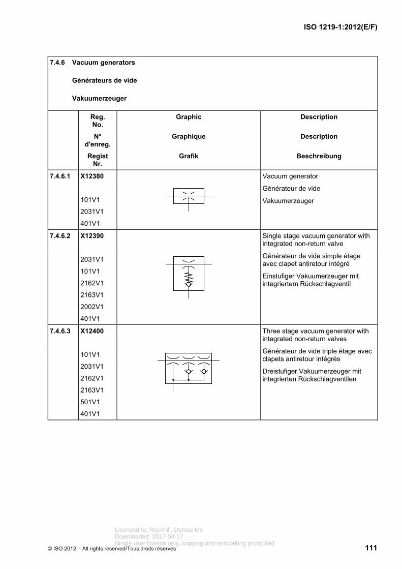
ISO 1219-1:2012(E/F)
© ISO 2012 – All rights reserved/Tous droits réservés 111
7.4.6 Vacuum generators
Générateurs de vide
Vakuumerzeuger
Reg. No.
N° d'enreg.
Regist Nr.
Graphic
Graphique
Grafik
Description
Description
Beschreibung
7.4.6.1 X12380
101V1
2031V1
401V1
Vacuum generator
Générateur de vide
Vakuumerzeuger
7.4.6.2 X12390
2031V1
101V1
2162V1
2163V1
2002V1
401V1
Single stage vacuum generator with integrated non-return valve
Générateur de vide simple étage avec clapet antiretour intégré
Einstufiger Vakuumerzeuger mit integriertem Rückschlagventil
7.4.6.3 X12400
101V1
2031V1
2162V1
2163V1
501V1
401V1
Three stage vacuum generator with integrated non-return valves
Générateur de vide triple étage avec clapets antiretour intégrés
Dreistufiger Vakuumerzeuger mit integrierten Rückschlagventilen
Licensed to: Rockhill, Denise MsDownloaded: 2017-04-17Single user licence only, copying and networking prohibited

ISO 1219-1:2012(E/F)
112 © ISO 2012 – All rights reserved/Tous droits réservés
7.4.6.4 X12410
101V7
F027V1
101V2
212V1
2031V1
2162V1
2163V1
501V1
401V1
422V1
422V1
2002V1
Single stage vacuum generator with blow-off valve
Générateur de vide simple étage avec vanne d'échappement
Einstufiger Vakuumerzeuger mit Entlüftungsventil
7.4.7 Suction cups
Ventouses
Saugnäpfe
Reg. No.
N° d'enreg.
Regist Nr.
Graphic
Graphique
Grafik
Description
Description
Beschreibung
7.4.7.1 X12420
F073V1
Suction cup
Ventouse
Saugnapf
7.4.7.2 X12430
F073V1
2162V2
2163V2
2002V2
Suction cup with spring loaded stem and non-return valve
Ventouse avec tige à ressort et clapet antiretour
Saugnapf mit Rückholfeder und Rückschlagventil
Licensed to: Rockhill, Denise MsDownloaded: 2017-04-17Single user licence only, copying and networking prohibited

ISO 1219-1:2012(E/F)
© ISO 2012 – All rights reserved/Tous droits réservés 113
8 Symbols of basic nature
Symboles de base
Grundsymbole
8.1 Lines
Traits
Linien
Reg. No.
N° d'enreg.
Regist Nr.
Graphic
Graphique
Grafik
Description
Description
Beschreibung
8.1.1 401V1
Supply line, return line, component enclosure and symbol enclosure (see ISO 128)
Conduite d'alimentation, conduite de retour, encadrement du composant et encadrement du symbole (voir l'ISO 128)
Versorgungsleitung, Rücklaufleitung, Bauteilumrahmung und Symbolumrandung (siehe ISO 128)
8.1.2 422V1
Internal and external pilot (control) line, drain line, flushing line, bleed line (see ISO 128)
Conduite de pilotage (commande) interne et externe, conduite de drainage des fuites, conduite de rinçage, conduite de purge (voir l'ISO 128)
Interne und externe Steuerleitung, Leckölleitung, Spülleitung, Entlüftungsleitung (siehe ISO 128)
8.1.3 F001V1
Frame for several components (see ISO 128)
Cadre pour différents composants (voir l'ISO 128)
Rahmen für mehrere Bauteile (siehe ISO 128)
Licensed to: Rockhill, Denise MsDownloaded: 2017-04-17Single user licence only, copying and networking prohibited

ISO 1219-1:2012(E/F)
114 © ISO 2012 – All rights reserved/Tous droits réservés
8.2 Connections and joints
Connexions et raccordements
Verbindungen und Anschlüsse
Reg. No.
N° d'enreg.
Regist Nr.
Graphic
Graphique
Grafik
Description
Description
Beschreibung
8.2.1 501V1
Connection of two fluid lines
Point de raccordement pour canalisations de fluide
Verbindung zweier Fluidleitungen
8.2.2 501V2
Connection of two fluid lines (within a symbol)
Point de raccordement pour canalisations de fluide (à l'intérieur d'un symbole)
Verbindung zweier Fluidleitungen (innerhalb eines Symbols)
8.2.3 401V2
Port
Orifice de raccordement
Anschluss
8.2.4 F035V1
Port with pilot line or drain line
Orifice de raccordement avec conduite de pilotage ou de drainage
Steuer- oder Leckölanschluss
8.2.5 422V2
Pilot line within a pressure-relief valve
Conduite de pilotage à l'intérieur d'un limiteur de pression
Steuerleitung innerhalb eines Druckbegrenzungsventils
8.2.6 422V3
Pilot line within a pressure-reducing valve
Conduite de pilotage à l'intérieur d'un réducteur de pression
Steuerleitung innerhalb eines Druckreduzierventils
Licensed to: Rockhill, Denise MsDownloaded: 2017-04-17Single user licence only, copying and networking prohibited

ISO 1219-1:2012(E/F)
© ISO 2012 – All rights reserved/Tous droits réservés 115
8.2.7 422V4
Pilot line within a three-port pressure-reducing valve
Conduite de pilotage à l'intérieur d'un réducteur de pression à trois voies
Steuerleitung innerhalb eines Dreiwege-Druckreduzierventils
8.2.8 452V1
Flexible line and accumulator bladder
Conduite flexible et vessie
Flexible Leitung und Trennglied Blase
8.2.9 2172V1
Closed path or port
Voie ou orifice de raccordement fermé
Verschlossener Weg oder Anschluss
8.2.10 F038V1
Plug inside a fluid line
Bouchon à l'intérieur d'une conduite de fluide
Stopfen innerhalb einer Fluidleitung
8.2.11 F036V1
Rotary joint
Raccord union rotatif
Drehverbindung
8.2.12 F037V1
Three-way ball valve
Robinet trois voies á boisseau sphérique
Drei-Wege-Kugelhahn
Licensed to: Rockhill, Denise MsDownloaded: 2017-04-17Single user licence only, copying and networking prohibited

ISO 1219-1:2012(E/F)
116 © ISO 2012 – All rights reserved/Tous droits réservés
8.3 Flow paths and direction indicators
Voies d'écoulement et indicateurs de sens
Volumenstromwege und Richtungsanzeiger
Reg. No.
N° d'enreg.
Regist Nr.
Graphic
Graphique
Grafik
Description
Description
Beschreibung
8.3.1 F026V1
Path and direction of a flow through a valve
Voie et sens d'un écoulement à travers un distributeur
Weg und Richtung eines Volumenstroms durch ein Ventil
8.3.2 F027V1
Path and direction of a flow through a valve
Voie et sens d'un écoulement à travers un distributeur
Weg und Richtung eines Volumenstroms durch ein Ventil
8.3.3 F028V1
Path and direction of a flow through a valve
Voie et sens d'un écoulement à travers un distributeur
Weg und Richtungen eines Volumenstroms durch ein Ventil
8.3.4 F029V1
Path and direction of a fluid flow through a valve
Voie et sens d'un écoulement à travers un distributeur
Weg und Richtungen eines Volumenstroms durch ein Ventil
8.3.5 F030V1
Path of the flow within a valve
Voie de l'écoulement à l'intérieur d'un distributeur
Weg des Volumenstroms innerhalb eines Ventils
8.3.6 F031V1
Path of the flow within a valve
Voie de l'écoulement à l'intérieur d'un distributeur
Weg des Volumenstroms innerhalb eines Ventils
Licensed to: Rockhill, Denise MsDownloaded: 2017-04-17Single user licence only, copying and networking prohibited
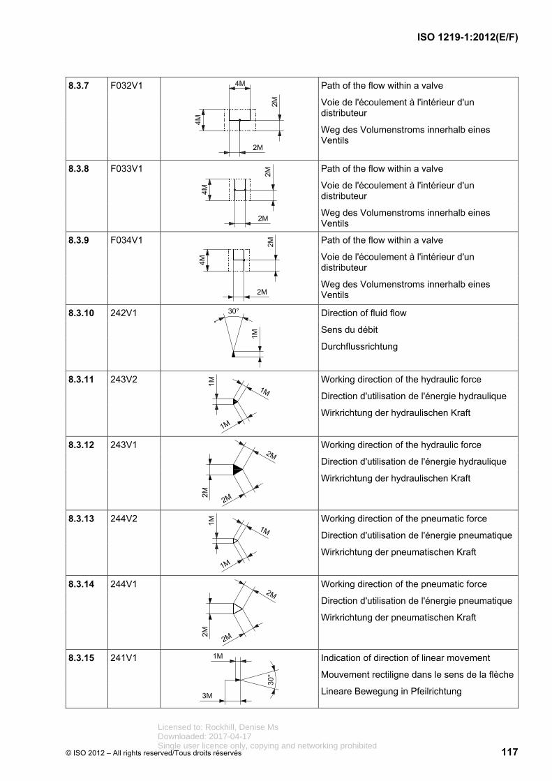
ISO 1219-1:2012(E/F)
© ISO 2012 – All rights reserved/Tous droits réservés 117
8.3.7 F032V1
Path of the flow within a valve
Voie de l'écoulement à l'intérieur d'un distributeur
Weg des Volumenstroms innerhalb eines Ventils
8.3.8 F033V1
Path of the flow within a valve
Voie de l'écoulement à l'intérieur d'un distributeur
Weg des Volumenstroms innerhalb eines Ventils
8.3.9 F034V1
Path of the flow within a valve
Voie de l'écoulement à l'intérieur d'un distributeur
Weg des Volumenstroms innerhalb eines Ventils
8.3.10 242V1
Direction of fluid flow
Sens du débit
Durchflussrichtung
8.3.11 243V2
Working direction of the hydraulic force
Direction d'utilisation de l'énergie hydraulique
Wirkrichtung der hydraulischen Kraft
8.3.12 243V1
Working direction of the hydraulic force
Direction d'utilisation de l'énergie hydraulique
Wirkrichtung der hydraulischen Kraft
8.3.13 244V2
Working direction of the pneumatic force
Direction d'utilisation de l'énergie pneumatique
Wirkrichtung der pneumatischen Kraft
8.3.14 244V1
Working direction of the pneumatic force
Direction d'utilisation de l'énergie pneumatique
Wirkrichtung der pneumatischen Kraft
8.3.15 241V1
Indication of direction of linear movement
Mouvement rectiligne dans le sens de la flèche
Lineare Bewegung in Pfeilrichtung
Licensed to: Rockhill, Denise MsDownloaded: 2017-04-17Single user licence only, copying and networking prohibited

ISO 1219-1:2012(E/F)
118 © ISO 2012 – All rights reserved/Tous droits réservés
8.3.16 245V1 Indication of linear movement in both directions
Mouvement rectiligne bidirectionnel
Lineare Bewegung in zwei Richtungen
8.3.17 255V1 Arrow showing clockwise direction of rotation
Flèche du sens de rotation, dans le sens des aiguilles d'une montre
Richtungspfeil zeigt Drehung im Uhrzeigersinn
8.3.18 255V2 Arrow showing counter-clockwise direction of rotation
Flèche du sens de rotation, dans le sens inverse des aiguilles d'une montre
Richtungspfeil zeigt Drehung im Gegenuhrzeigersinn
8.3.19 256V1 Arrow showing rotation in both directions
Flèche du sens de rotation, dans les deux sens
Richtungspfeil zeigt Drehung in beide Richtungen
8.3.20 148V1
Arrow for display units, pressure
Flèche pour indicateurs, pression
Pfeil für Anzeigegeräte, Druck
8.3.21 F024V1 Indication of torque
Indicateur de couple
Anzeige für Drehmoment
8.3.22 F025V1 Indication of speed
Indicateur de vitesse de rotation
Anzeige für Drehzahl
Licensed to: Rockhill, Denise MsDownloaded: 2017-04-17Single user licence only, copying and networking prohibited

ISO 1219-1:2012(E/F)
© ISO 2012 – All rights reserved/Tous droits réservés 119
8.4 Basic mechanical elements
Éléments de base mécaniques
Mechanische Grundelemente
Reg. No.
N° d'enreg.
Regist Nr.
Graphic
Graphique
Grafik
Description
Description
Beschreibung
8.4.1 2163V2
Moving part of a non-return (check) valve, small
Partie mobile d'un clapet antiretour, petite taille
Bewegliches Teil eines Rückschlagventils, klein
8.4.2 2163V1
Moving part of a non-return valve, large
Partie mobile d'un clapet antiretour, grande taille
Bewegliches Teil eines Rückschlagventils, groß
8.4.3 F002V1
Frame for measuring instrument
Control element
Stepping motor
Cadre pour instrument de mesure
Organe de commande
Moteur pas à pas
Rahmen für Messgerät Betätigungselement
Schrittmotor
8.4.4 2065V1
Frame for energy conversion unit (pump, compressor, motor)
Cadre pour unité de transformation de l'énergie (pompe, compresseur, moteur)
Rahmen für Energieumformungseinheit (Pumpe, Kompressor, Motor)
Licensed to: Rockhill, Denise MsDownloaded: 2017-04-17Single user licence only, copying and networking prohibited

ISO 1219-1:2012(E/F)
120 © ISO 2012 – All rights reserved/Tous droits réservés
8.4.5 F003V1
Frame for semi-rotary pump or motor (swivel drive)
Cadre pour moteur ou pompe à angle de rotation limité (entraînement par pivotement)
Rahmen für Motor oder Pumpe mit begrenztem Rotationswinkel (Schwenkantrieb)
8.4.6 101V21
Frame for control methods (shortened version), weight in accumulator or lubrication points
Cadre pour modes de commande (version simplifiée), contrepoids dans un accumulateur ou point de lubrification
Rahmen für Betätigungseinrichtung (verkürzte Ausführung), Gewicht im Speicher oder Schmierstellen
8.4.7 101V5
Frame for switch, converter and other devices
Cadre pour commutateur, convertisseur et autres appareils
Rahmen für Schalter, Wandler und andere Geräte
8.4.8 101V7
Functional unit for valves with maximum four main ports
Unité fonctionnelle pour distributeurs à quatre orifices principaux de raccordement au maximum
Funktionseinheit für Ventile mit maximal vier Hauptanschlüssen
8.4.9 101V12
Frame for drive unit motor (combustion engine)
Cadre pour module d'entraînement (moteur à combustion)
Rahmen für Antriebseinheit Motor (Verbrennungsmotor)
Licensed to: Rockhill, Denise MsDownloaded: 2017-04-17Single user licence only, copying and networking prohibited

ISO 1219-1:2012(E/F)
© ISO 2012 – All rights reserved/Tous droits réservés 121
8.4.10 101V15
Frame for fluid conditioning components (filters, separators, lubricators and heat exchangers)
Cadre pour appareil de préparation (filtre, séparateur, lubrificateur, échangeur de chaleur)
Kontur für Aufbereitungsgerät (Filter, Abscheider, Schmiergerät, Wärmetauscher)
8.4.11 101V2
Frame for control methods (standard version)
Cadre pour modes de commande (version standard)
Rahmen für Betätigungseinrichtung (Standardausführung)
8.4.12 101V3
Frame for control methods (elongated version)
Cadre pour modes de commande (version longue)
Rahmen für Betätigungseinrichtung (verlängerte Ausführung)
8.4.13 101V6
Frame for display units
Cadre pour indicateur
Rahmen für Anzeigegeräte
8.4.14 101V8
Functional unit for valves with five main ports
Unité fonctionnelle pour distributeur à cinq orifices principaux de raccordement
Funktionseinheit für Ventile mit fünf Hauptanschlüssen
8.4.15 101V16
Functional unit for a dual pressure valve (AND function)
Unité fonctionnelle pour un distributeur à deux pressions (fonction ET)
Funktionseinheit für ein Zweidruckventil (UND – Funktion)
8.4.16 101V20
Carriage of a rodless cylinder
Chariot d'un vérin sans tige
Schlitten eines stangenlosen Zylinders
Licensed to: Rockhill, Denise MsDownloaded: 2017-04-17Single user licence only, copying and networking prohibited

ISO 1219-1:2012(E/F)
122 © ISO 2012 – All rights reserved/Tous droits réservés
8.4.17 101V1
Functional unit
Unité fonctionnelle
Funktionseinheit
8.4.18 101V17
Gripper frame
Contour de grappin
Greiferkontur
8.4.19 101V18
Piston rod for plunger cylinder
Tige de piston pour vérin plongeur
Kolbenstange für Plungerzylinder
8.4.20 101V13
Cylinder frame
Contour de vérin
Zylinderkontur
8.4.21 101V22
Frame for telescopic cylinder
Cadre pour vérin télescopique
Rahmen Teleskopzylinder
8.4.22 F004V1
Piston rod
Tige de piston
Kolbenstange
8.4.23 F004V2
Piston rod with a large diameter
Tige de piston de grand diamètre
Kolbenstange mit großem Durchmesser
8.4.24 F004V3
Piston rod for telescopic cylinder
Tige de piston pour vérin télescopique
Kolbenstange für Teleskopzylinder
8.4.25 F005V1
Piston rod for double-acting telescopic cylinder
Tige de piston pour vérin télescopique à double effet
Kolbenstange für doppeltwirkenden Teleskopzylinder
Licensed to: Rockhill, Denise MsDownloaded: 2017-04-17Single user licence only, copying and networking prohibited

ISO 1219-1:2012(E/F)
© ISO 2012 – All rights reserved/Tous droits réservés 123
8.4.26 F005V2
Piston rod for double-acting telescopic cylinder
Tige de piston pour vérin télescopique à double effet
Kolbenstange für doppeltwirkenden Teleskopzylinder
8.4.27 661V1
Latching device that requires an independent control element to be unlocked
Dispositif d'accrochage, le déverrouillage se fait par un organe de commande indépendant
Arretierungsvorrichtung; zum Lösen der Blockade ist ein separates Betätigungselement erforderlich
8.4.28 326V1
Permanent magnet
Aimant permanent
Permanentmagnet
8.4.29 F006V1
Diaphragm piston, bladder
Piston à diaphragme, vessie
Membrankolben, Blase
8.4.30 F007V1
Pressure intensifier housing
Boîtier d'amplificateur de pression
Gehäuse für Druckübersetzer
8.4.31 F008V1
Piston of a pressure intensifier
Piston d'amplificateur de pression
Kolben für Druckübersetzer
8.4.32 F009V1
Element for gripper, from the outside
Élément pour grappin, de l'extérieur
Element für Greifer, von außen
Licensed to: Rockhill, Denise MsDownloaded: 2017-04-17Single user licence only, copying and networking prohibited

ISO 1219-1:2012(E/F)
124 © ISO 2012 – All rights reserved/Tous droits réservés
8.4.33 F009V2
Element for gripper, from inside
Élément pour grappin, de l'intérieur
Element für Greifer, von innen
8.4.34 2174V1
Air outlet without a connection possibility
Sortie d'air sans possibilité de connexion
Entlüftung ohne Anschlussmöglichkeit
8.4.35 101V19
Cushioning in a cylinder
Amortissement à l'intérieur d'un vérin
Dämpfung in einem Zylinder
8.4.36 101V14
Piston for a cylinder
Piston d'un vérin
Kolben eines Zylinders
8.4.37 101V9
Spool for slip-in cartridge valve
Piston pour distributeur à cartouche à bride
Kolben für Einsteck-Einbauventil
8.4.38 101V10
Mounting insert for slip-in cartridge valve, spool valve design
Espace de montage pour distributeur à cartouche à bride, conception à tiroir
Einbauraum für Einsteck-Einbauventil, Schieberausführung
8.4.39 101V11
Spool for slip-in cartridge valve, spool valve design
Piston pour distributeur à cartouche à bride, conception à tiroir
Kolben für Einsteck-Einbauventil, Schieberausführung
Licensed to: Rockhill, Denise MsDownloaded: 2017-04-17Single user licence only, copying and networking prohibited

ISO 1219-1:2012(E/F)
© ISO 2012 – All rights reserved/Tous droits réservés 125
8.4.40 F010V1
Installation area for slip-in cartridge valve
Espace de montage pour distributeur à cartouche à bride
Einbauraum für Einsteck-Einbauventil
8.4.41 F011V1
Spool for slip-in cartridge valve, poppet design
Piston pour distributeur à cartouche à bride, conception à clapet
Kolben für Einsteck-Einbauventil, Sitzausführung
8.4.42 F012V1
Spool for slip-in cartridge valve, poppet design
Piston pour distributeur à cartouche à bride, conception à clapet
Kolben für Einsteck-Einbauventil, Sitzausführung
8.4.43 F013V1
Mounting insert for slip-in cartridge valve, active poppet insert
Espace de montage pour distributeur à cartouche à bride, cartouche à bride de type actif
Einbauraum für Einsteck-Einbauventil, aktiver Einbausatz
8.4.44 F014V1
Spool for slip-in cartridge valve, active poppet design insert
Piston pour distributeur à cartouche à bride, cartouche à bride de type actif
Kolben für Einsteck-Einbauventil, aktiver Sitzeinbausatz
8.4.45 F015V1
Piston for slip-in cartridge valve, active poppet insert
Piston pour distributeur à cartouche à bride, cartouche à bride de type actif
Kolben für Einsteck-Einbauventil, aktiver Sitzeinbausatz
Licensed to: Rockhill, Denise MsDownloaded: 2017-04-17Single user licence only, copying and networking prohibited

ISO 1219-1:2012(E/F)
126 © ISO 2012 – All rights reserved/Tous droits réservés
8.4.46 F016V1
Control cover without ports
The minimum cover height is 4M. For extended functions, the cover height shall be adjusted in multiples of 2M.
Couvercle de pilotage sans orifice
La hauteur minimale du couvercle est de 4M. Pour des fonctions étendues, la hauteur du couvercle doit être réglée par multiples de 2M.
Steuerdeckel ohne Anschlüsse
Die minimale Deckelhöhe ist 4M. Für erweiterte Funktionen wird die Deckelhöhe angepasst und ist ein Vielfaches von 2M.
8.4.47 402V1
Mechanical link, shaft, lever, mechanical feedback
Connexion mécanique, arbre, levier, rétroaction mécanique
Mechanische Verbindung, Welle, Hebel, mechanische Rückführung
8.4.48 F017V1
Mechanical connection (shaft, lever)
Connexion mécanique (arbre, levier)
Mechanische Verbindung (Welle, Hebel)
8.4.49 402V5
Mechanical link, shaft, lever, mechanical feedback
Connexion mécanique, arbre, levier, rétroaction mécanique
Mechanische Verbindung, Welle, Hebel, mechanische Rückführung
8.4.50 F018V1
Shaft coupling
Accouplement de l'arbre
Wellenkupplung
Licensed to: Rockhill, Denise MsDownloaded: 2017-04-17Single user licence only, copying and networking prohibited

ISO 1219-1:2012(E/F)
© ISO 2012 – All rights reserved/Tous droits réservés 127
8.4.51 F019V2
M to designate a motor in combination with symbol 2065V1
M pour désigner un moteur en combinaison avec le symbole 2065V1
M zur Kennzeichnung eines Motors in Verbindung mit Symbol 2065V1
8.4.52 F023V1
Element for vacuum pump
Élément de pompe à vide
Element für Vakuumpumpe
8.4.53 2162V2
Seat of a non-return (check) valve, small size
Siège du clapet antiretour, petite taille
Sitz eines Rückschlagventils, klein
8.4.54 2162V1
Seat of a non-return (check valve), large size
Siège du clapet antiretour, grande taille
Sitz eines Rückschlagventils, groß
8.4.55 F020V1
Mechanical stroke limiter
Limiteur de course mécanique
Mechanische Hubbegrenzung
8.4.56 2031V21
Throttle (small size)
Gicleur (petite taille)
Drossel (klein)
Licensed to: Rockhill, Denise MsDownloaded: 2017-04-17Single user licence only, copying and networking prohibited

ISO 1219-1:2012(E/F)
128 © ISO 2012 – All rights reserved/Tous droits réservés
8.4.57 2031V1
Flow control valve, restriction with a throttle path, viscosity dependent
Gicleur, portion d'étranglement en paroi longue, fonction de la viscosité
Drossel, Engstelle mit Drossellänge, viskositätsabhängig
8.4.58 F021V1
Orifice (small size)
Diaphragme (petite taille)
Blende (klein)
8.4.59 F022V1
Orifice, restriction with sharp edges, largely independent of viscosity
Diaphragme, portion d'étranglement peu sensible à la viscosité
Blende, Engstelle scharfkantig, weitgehend viskositätsunabhängig
8.4.60 2002V2
Spring for inserts
Ressort pour cartouches
Feder für Einbausätze
8.4.61 2002V4
Spring for gripper
Ressort pour grappin
Feder für Greifer
8.4.62 2002V3
Spring for cylinder
Ressort pour vérin
Feder für Zylinder
Licensed to: Rockhill, Denise MsDownloaded: 2017-04-17Single user licence only, copying and networking prohibited

ISO 1219-1:2012(E/F)
© ISO 2012 – All rights reserved/Tous droits réservés 129
8.5 Control mechanisms elements
Éléments de mécanismes de commande
Elemente für Betätigungseinrichtungen
Reg. No.
N° d'enreg.
Regist Nr.
Graphic
Graphique
Grafik
Description
Description
Beschreibung
8.5.1 F039V1
Element for locking settings (lock)
Élément pour le verrouillage des réglages (verrou)
Element zum Sichern der Einstellungen (Schloss)
8.5.2 402V2
Mechanical link, shaft, lever
Connexion mécanique, arbre, levier
Mechanische Verbindung, Welle, Hebel
8.5.3 402V3
Mechanical link, shaft, lever
Connexion mécanique, arbre, levier
Mechanische Verbindung, Welle, Hebel
8.5.4 402V4
Mechanical link, shaft, lever
Connexion mécanique, arbre, levier
Mechanische Verbindung, Welle, Hebel
8.5.5 F040V1
Mechanical link for a dual pressure valve
Connexion mécanique pour un distributeur à deux niveaux de pression
Mechanische Verbindung für ein Zweidruckventil
8.5.6 655V1
Detent
Dispositif de maintien en position
Raste
8.5.7 F041V1
Detent lock
Verrouillage du dispositif de maintien en position
Arretierungselement für Raste
Licensed to: Rockhill, Denise MsDownloaded: 2017-04-17Single user licence only, copying and networking prohibited

ISO 1219-1:2012(E/F)
130 © ISO 2012 – All rights reserved/Tous droits réservés
8.5.8 658V1
Indication of a non-detentable position
Représentation d'une position de commutation sans possibilité de maintien en position
Darstellung einer nicht rastbaren Schaltstellung
8.5.9 681V2 Element for manual override
Élément de commande auxiliaire manuelle
Element für Handhilfsbetätigung
8.5.10 682V1 Element for control mechanism operated by pushing
Élément de commande à poussoir
Element zur Betätigung durch Drücken
8.5.11 683V1 Element for control mechanism operated by pulling
Élément de commande à tirette
Element zur Betätigung durch Ziehen
8.5.12 684V1 Element for push-pull control mechanism
Élément de commande à poussoir et tirette
Element zur Betätigung durch Drücken und Ziehen
8.5.13 685V1 Element for control mechanism operated by turning
Élément de commande à tourner
Element zur Betätigung durch Drehen
8.5.14 686V1 Control element: removable grip
Élément de commande: clé amovible
Betätigungselement: abnehmbarer Griff
8.5.15 687V1
Control element: key
Élément de commande: clé
Betätigungselement: Schlüssel
Licensed to: Rockhill, Denise MsDownloaded: 2017-04-17Single user licence only, copying and networking prohibited

ISO 1219-1:2012(E/F)
© ISO 2012 – All rights reserved/Tous droits réservés 131
8.5.16 688V1
Control element: lever
Élément de commande: levier
Betätigungselement: Hebel
8.5.17 689V1
Control element: pedal
Élément de commande: pédale
Betätigungselement: Pedal
8.5.18 690V1
Control element: treadle
Élément de commande: bascule
Betätigungselement: Wippe
8.5.19 692V1
Device for restricting access to control mechanism
Dispositif pour accès limité à l'actionneur
Einrichtung für eingeschränkten Zugriff zum Betätigungselement
8.5.20 711V1
Control element: plunger
Élément de commande: poussoir
Betätigungselement: Stößel
8.5.21 2005V1
Rotary joint connection
Raccordement articulé pour éléments de commande
Gelenkverbindung für Betätigungselemente
8.5.22 712V1
Control element: roller
Élément de commande: galet
Betätigungselement: Rolle
Licensed to: Rockhill, Denise MsDownloaded: 2017-04-17Single user licence only, copying and networking prohibited

ISO 1219-1:2012(E/F)
132 © ISO 2012 – All rights reserved/Tous droits réservés
8.5.23 2002V1
Control element: spring
Élément de commande: ressort
Betätigungselement: Feder
8.5.24 F042V1
Control element: spring with control mechanism
Élément de commande: mécanisme de pilotage à ressort
Betätigungselement: Federstab
8.5.25 2177V1
Direct operation by opposing control areas of different size
Commande à action directe par surfaces de commande opposées de tailles différentes
Direktwirkende Betätigung durch unterschiedlich große, sich gegenüberliegende Steuerflächen
8.5.26 211V1
Symbol for stepwise adjustability
Symbole pour possibilité de réglage graduel
Symbol für schrittweise Verstellbarkeit
8.5.27 F019V2
M to designate a motor in combination with symbol F002V1
M pour désignation d'un moteur rapporté au symbole F002V1
M zur Kennzeichnung eines Motors in Verbindung mit Symbol F002V1.
8.5.28 F043V1
Direct operation through hydraulic pressurization (for directional control valves)
Commande à action directe par application de pression hydraulique (pour distributeurs de commande directionnels)
Direktwirkende Betätigung durch hydraulische Druckbeaufschlagung (für Wegeventile)
8.5.29 F044V1
Direct operation through pneumatic pressurization (for directional control valves)
Commande à action directe par application de pression pneumatique (pour distributeurs de commande directionnels)
Direktwirkende Betätigung durch pneumatische Druckbeaufschlagung (für Wegeventile)
Licensed to: Rockhill, Denise MsDownloaded: 2017-04-17Single user licence only, copying and networking prohibited

ISO 1219-1:2012(E/F)
© ISO 2012 – All rights reserved/Tous droits réservés 133
8.5.30 212V1
Control element: winding, direction of actuation towards the valving element
Élément de commande: enroulement, agissant vers le composant de distributeur
Betätigungselement: Wicklung, Wirkrichtung gegen Ventilelement
8.5.31 212V2
Control element: winding, direction of actuation away from the valving element
Élément de commande: enroulement, agissant à partir du composant de distributeur
Betätigungselement: wicklung, Wirkrichtung weg vom Ventilelement
8.5.32 212V4
Control element: two windings, working in opposing directions
Élément de commande: deux enroulements agissant en sens contraire
Betätigungselement: Zwei gegensinnig wirkende Wicklungen
8.6 Adjusting elements
Éléments de réglage
Verstellelemente
Reg. No.
N° d'enreg.
Regist Nr.
Graphic
Graphique
Grafik
Description
Description
Beschreibung
8.6.1 201V1
Adjustability, e.g. stroke limitation
Réglage, par exemple limitation de course
Einstellbarkeit z.B. Hubbegrenzung
8.6.2 203V1
Pre-setting, e.g. stroke limitation
Préréglage, par exemple limitation de course
Voreinstellung z.B. Hubbegrenzung
8.6.3 201V2
Possible adjustability of a spring or of a proportional solenoid
Possibilité de réglage d'un ressort ou d'un électroaimant proportionnel
Mögliche Verstellbarkeit einer Feder oder eines Proportionalmagneten
Licensed to: Rockhill, Denise MsDownloaded: 2017-04-17Single user licence only, copying and networking prohibited

ISO 1219-1:2012(E/F)
134 © ISO 2012 – All rights reserved/Tous droits réservés
8.6.4 201V3
Possible adjustability of an orifice
Possibilité de réglage d'un diaphragme
Mögliche Verstellbarkeit einer Blende
8.6.5 203V2
Pre-setting, orifice
Préréglage, diaphragme
Voreinstellung, Blende
8.6.6 201V4
Possible adjustability of a throttle
Possibilité de réglage d'un gicleur
Mögliche Verstellbarkeit einer Drossel
8.6.7 201V7
Possible adjustability of end cushioning
Possibilité de réglage d'un amortissement de fin de course
Mögliche Verstellbarkeit einer Endlagendämfung
8.6.8 201V5
Possible pump/motor adjustability
Possibilité de réglage d'une pompe/d'un moteur
Mögliche Verstellbarkeit einer Pumpe/eines Motors
Licensed to: Rockhill, Denise MsDownloaded: 2017-04-17Single user licence only, copying and networking prohibited

ISO 1219-1:2012(E/F)
© ISO 2012 – All rights reserved/Tous droits réservés 135
8.7 Accessories
Accessoires
Zubehör
Reg. No.
N° d'enreg.
Regist Nr.
Graphic
Graphique
Grafik
Description
Description
Beschreibung
8.7.1 753V1
Signal converter, general Measuring transducer
Convertisseur de signaux, en général Capteur de mesure
Signalwandler allgemein Messumformer
8.7.2 753V2
Signal converter, general measuring transducer
Convertisseur de signaux, en général Capteur de mesure
Signalwandler allgemein Messumformer
8.7.3 F045V1
* = input signal ** = output signal
* = signal d'entrée ** = signal de sortie
* = Eingangssignal ** = Ausgangssignal
8.7.4 F046V1 F = Flow rate, débit volumétrique, Volumenstrom
G = Gauging position or length, mesure du déplacement ou de la position, Messung Weg oder Position
L = Level, niveau, Niveau
P = Pressure or vacuum, pression ou vide, Druck oder Vacuum
S = Speed or frequency, vitesse ou fréquence, Geschwindigkeit oder Frequenz
T = Temperature, température, Temperatur
W = Weight or force, poids ou force, Gewicht oder Kraft
Input signal
Signal d'entrée
Eingangsignal
Licensed to: Rockhill, Denise MsDownloaded: 2017-04-17Single user licence only, copying and networking prohibited

ISO 1219-1:2012(E/F)
136 © ISO 2012 – All rights reserved/Tous droits réservés
8.7.5 F047V1
Element for piezo-electric control mechanism
Élément pour mécanisme de commande piézoélectrique
Element für piezoelektrische Betätigung
8.7.6 435V1
Symbol for electric line
Symbole d'un câble électrique
Kennzeichnung einer elektrischen Leitung
8.7.7 F048V1
Output signal, electrically switching
Commutation électrique de signal de sortie
Ausgangssignal, elektrisch schaltend
8.7.8 234V1
Output signal, electrical analogue
Signal de sortie électrique analogique
Ausgangssignal, elektrisch analoge
8.7.9 235V1
Output signal, electrical digital
Signal de sortie électrique numérique
Ausgangssignal, elektrisch digital
8.7.10 F049V1
Electrical contact, break-contact
Contact électrique, contact d'ouverture
Elektrischer Kontakt, Öffner
8.7.11 F050V1
Electrical contact, make-contact
Contact électrique, contact de fermeture
Elektrischer Kontakt, Schließer
Licensed to: Rockhill, Denise MsDownloaded: 2017-04-17Single user licence only, copying and networking prohibited

ISO 1219-1:2012(E/F)
© ISO 2012 – All rights reserved/Tous droits réservés 137
8.7.12 F051V1
Electrical contact, changeover switch
Contact électrique, contact inverseur
Elektrischer Kontakt, Wechsler
8.7.13 F052V1
Integrated electronics
Électronique intégrée
Integrierte Elektronik
8.7.14 1103V1
Indication of fluid level
Indicateur de niveau du fluide
Anzeige für Flüssigkeitsniveau
8.7.15 F053V1
Sign for a summator
Symbole pour somme
Zeichen für Summierer
8.7.16 F054V1
Indication of flow
Indicateur de débit
Anzeige für Volumenstrom
8.7.17 F055V1
Indication of temperature
Indicateur de température
Anzeigeelement für Temperatur
8.7.18 F056V1
Element of an optical indicator
Élément d'indicateur optique
Element für optische Anzeige
8.7.19 F057V1
Element for acoustical indication
Élément pour signal acoustique
Element für akustisches Signal
Licensed to: Rockhill, Denise MsDownloaded: 2017-04-17Single user licence only, copying and networking prohibited

ISO 1219-1:2012(E/F)
138 © ISO 2012 – All rights reserved/Tous droits réservés
8.7.20 F058V1
Element for float switch
Élément pour contacteur de niveau
Element für Schwimmerschalter
8.7.21 F059V1
Element for time-dependent control unit
Élément pour appareil de commande temporisé
Element für zeitabhängiges Steuergerät
8.7.22 F060V1
Element for counter
Élément pour compteur
Element für Zähler
8.7.23 2101V1
Shut-off valve
Robinet d'isolement
Absperrventil
8.7.24 F061V1
Filter element
Élément filtrant
Filterelement
8.7.25 F062V1
Coalescing function in a filter
Élément coalescent d'un filtre
Feinfilterelement eines Filters
8.7.26 F063V1
Vacuum function in a filter
Élément de vide d'un filtre
Vakuumelement eines Filters
8.7.27 F064V1
Element for fluid separator, with manual drain
Élément pour séparateur de fluide, à purge manuelle
Element für Flüssigkeitsabscheider mit manuellem Ablass
Licensed to: Rockhill, Denise MsDownloaded: 2017-04-17Single user licence only, copying and networking prohibited

ISO 1219-1:2012(E/F)
© ISO 2012 – All rights reserved/Tous droits réservés 139
8.7.28 F074V1
Element for separator
Élément pour séparateur
Element für Abscheider
8.7.29 F065V1
Element for automatic fluid separator
Élément pour séparateur de fluide automatique
Element für automatischen Flüssigkeitsabscheider
8.7.30 F066V1
Centrifugal element of filter
Élément centrifuge d'un filtre
Zentrifugalelement eines Filters
8.7.31 F067V1
Element of heat exchange
Élément d'échangeur de chaleur
Element eines Wärmetauschers
8.7.32 F068V1
Reservoir
Réservoir
Behälter
8.7.33 2061V1
Return to reservoir
Retour au réservoir
Behälterrückführung
Licensed to: Rockhill, Denise MsDownloaded: 2017-04-17Single user licence only, copying and networking prohibited

ISO 1219-1:2012(E/F)
140 © ISO 2012 – All rights reserved/Tous droits réservés
8.7.34 F069V1
Element for:
pressurized reservoir,
compressed air reservoir,
accumulator,
gas bottle,
bellows actuator,
hose cylinder
Élément pour:
réservoir sous pression,
réservoir d'air comprimé,
accumulateur,
bouteille à gaz,
(actionneur à) soufflets,
vérin flexible
Element für:
druckvorgespannten Behälter,
Druckluftbehälter,
Speicher,
Gasflasche,
Balgzylinder,
Schlauchzylinder
8.7.35 F070V1
Pneumatic source of energy
Source d'énergie pneumatique
Pneumatische Energiequelle
8.7.36 F071V1
Hydraulic source of energy
Source d'énergie hydraulique
Hydraulische Energiequelle
Licensed to: Rockhill, Denise MsDownloaded: 2017-04-17Single user licence only, copying and networking prohibited

ISO 1219-1:2012(E/F)
© ISO 2012 – All rights reserved/Tous droits réservés 141
8.7.37 2033V1
Silencer
Silencieux
Schalldämpfer
8.7.38 F072V1
Fan
Ventilateur
Lüfter
8.7.39 F073V1
Suction cup
Ventouse
Saugnapf
Licensed to: Rockhill, Denise MsDownloaded: 2017-04-17Single user licence only, copying and networking prohibited

ISO 1219-1:2012(E/F)
142 © ISO 2012 – All rights reserved/Tous droits réservés
9 Application rules
Règles d'application
Anwendungsregeln
9.1 General symbols
Symboles généraux
Grundsymbole
Reg. No.
N° d'enreg.
Regist Nr.
Graphic
Graphique
Grafik
Description
Description
Beschreibung
9.1.1 RF001
The size of a functional unit may be changed as needed.
La taille d'une unité fonctionnelle peut être changée si nécessaire.
Die Größe der Funktionseinheit kann bedarfsgerecht verändert werden.
9.1.2 RF002
An air outlet without a connection possibility shall be shown when it is required by the functionality.
L'échappement d'air sans possibilité de raccordement doit être représenté si la compréhension de la fonctionnalité l'exige.
Die Entlüftung ohne Anschlussmöglichkeit ist dann zu zeichnen, wenn es die Eindeutigkeit der Funktionsdarstellung erfordert.
9.1.3 RF003
The elements shall be centrally positioned at a spacing of 1M to the relevant symbol.
Les éléments doivent être centrés à des intervalles de 1M du symbole.
Die Elemente müssen mittig im Abstand von 1M zum jeweiligen Symbol positioniert werden.
Licensed to: Rockhill, Denise MsDownloaded: 2017-04-17Single user licence only, copying and networking prohibited

ISO 1219-1:2012(E/F)
© ISO 2012 – All rights reserved/Tous droits réservés 143
9.2 Valves
Distributeurs
Ventile
Reg. No.
N° d'enreg.
Regist Nr.
Graphic
Graphique
Grafik
Description
Description
Beschreibung
9.2.1 RF004
The centre line of the control mechanisms is drawn 1M above the lower edge of the rectangle/square.
Centre lines of additional control mechanisms, acting in parallel, are drawn at a 2M pitch. There should be no protrusion below the lower line of the functional element.
Les organes de commande sont dessinés centrés sur un axe positionné à une distance de 1M au-dessus du bord inférieur du rectangle/du carré.
Les axes des autres organes de commande à action parallèle sont dessinés à un écartement de 2M. Il convient que le bord inférieur de l'unité fonctionnelle ne dépasse pas en dessous.
Die Mittellinie des Betätigungselementes wird im Abstand von 1M zur Rechteck/Quadrat-Unterkante angeordnet.
Weitere parallel wirkende Elemente werden davon im Abstand 2M dargestellt. Die Unterkante des Funktionselements sollte nicht unterschritten werden.
Licensed to: Rockhill, Denise MsDownloaded: 2017-04-17Single user licence only, copying and networking prohibited

ISO 1219-1:2012(E/F)
144 © ISO 2012 – All rights reserved/Tous droits réservés
9.2.2 RF005
Operation of one control mechanism results in a change from the rest position to the next position of the valving element, depending upon which control mechanism is actuated.
Operation of both control mechanisms at the same time in a four-position valve results in the valving element moving over two positions from the rest position.
Un actionnement unilatéral a toujours pour effet de commuter de la position neutre à la position suivante de commutation en fonction du dispositif de commande.
Un actionnement bilatéral simultané d'un distributeur à quatre positions a pour effet de commuter de la position neutre à deux positions plus loin.
Eine einseitige Betätigung bewirkt grundsätzlich den Wechsel von der Ruhestellung in die nächste der Betätigungseinrichtung zugewandte Schaltstellung (Position).
Eine gleichzeitige beidseitige Betätigung eines Vierstellungs-Wegeventils bewirkt den Wechsel von der Ruhestellung in die übernächste Schaltstellung.
9.2.3 RF006
The detent-locking device shall be positioned centrally, or 0,5M to the right or left of the notch, and 0,5M above the shaft.
Le verrouillage du dispositif de maintien en position doit être centré ou positionné à 0,5M à droite ou à gauche du crantage, à un écartement de 0,5M au-dessus de l'arbre.
Die Arretierung der Raste wird mittig oder 0,5M rechts bzw. links der Nut im Abstand von 0,5M oberhalb der Welle positioniert.
Licensed to: Rockhill, Denise MsDownloaded: 2017-04-17Single user licence only, copying and networking prohibited

ISO 1219-1:2012(E/F)
© ISO 2012 – All rights reserved/Tous droits réservés 145
9.2.4 RF007
The detent grooves shall be positioned symmetrically on the shaft.
For more than three detent positions, the number of positions may be shown by placing the figure above the detent with a space of 0,5M .
Les dispositifs de maintien en position sont positionnés symétriquement à la liaison mécanique.
Si le nombre de crantages est supérieur à trois, il est possible d'indiquer le nombre de positions par un chiffre placé au-dessus de l'élément de crantage à un écartement de 0,5M.
Rasten sind symmetrisch auf der mechanischen Verbindung anzuordnen.
Bei mehr als drei Raststellungen kann die Anzahl der Stellungen als Zahl oberhalb des Rastelementes im Abstand von 0,5M angegeben werden.
9.2.5 RF008
If necessary, a switch position without detent should be shown.
Il convient de représenter, si nécessaire, une position sans possibilité de crantage.
Falls erforderlich, ist eine nicht rastbare Schaltstellung darzustellen.
Licensed to: Rockhill, Denise MsDownloaded: 2017-04-17Single user licence only, copying and networking prohibited

ISO 1219-1:2012(E/F)
146 © ISO 2012 – All rights reserved/Tous droits réservés
9.2.6 RF009
Control mechanisms shall be drawn directly on the corresponding rectangle/square.
Les organes de commande doivent être directement dessinés sur le rectangle/le carré correspondant.
Betätigungselemente müssen direkt an das entsprechende Rechteck/Quadrat gezeichnet werden.
9.2.7 RF010
Control mechanisms shall be drawn on the right side of the rectangle/square unless they are represented on both sides.
Les organes de commande doivent être représentés sur le côté droit du carré/du rectangle, sauf s'ils existent des deux côtés.
Betätigungselemente werden, wenn nicht beidseitig vorhanden, auf der rechten Seite des Quadrats/Rechtecks dargestellt.
9.2.8 RF011
If the size of the symbol is insufficient to accommodate the control mechanisms, an extension line is drawn. This can be done on both sides of the functional element.
Si le côté d'un symbole ne suffit pas pour positionner les organes de commande, tracer une ligne verticale de jonction, éventuellement de part et d'autre de l'élément fonctionnel.
Reicht die Seite eines Symbols zur Positionierung der Betätigungselemente nicht aus, wird eine Verbindungslinie hochgezogen. Dies kann auch beidseitig des Betätigungselementes erfolgen.
Licensed to: Rockhill, Denise MsDownloaded: 2017-04-17Single user licence only, copying and networking prohibited
ISO 1219-1:2012(E/F)
© ISO 2012 – All rights reserved/Tous droits réservés 147
9.2.9 RF012
Control mechanisms and signal converters acting in parallel shall be arranged from bottom to top in the following order:
hydraulic/pneumatic
solenoid
spring
manual control element
converter
If identical control mechanisms are located on both sides of the functional element, their order must be located symmetrically. Overlapping of the symbols is not permitted.
Les organes de commande et les convertisseurs de signaux à action parallèle doivent être disposés de bas en haut dans l'ordre suivant:
hydraulique/pneumatique
électroaimant
ressort
commande manuelle
convertisseur
Lorsque des organes de commande identiques sont fournis des deux côtés de l'élément fonctionnel, ils doivent être représentés symétriquement. Le chevauchement des symboles n'est pas permis.
Parallel wirkende Betätigungs-elemente und Signalwandler werden von unten nach oben angeordnet und zwar in der Reihenfolge
hydraulisch/pneumatisch
Magnet
Feder
Handbetätigung
Wandler
Sind Betätigungselemente paarig vorhanden, müssen diese sym-metrisch dargestellt werden. Lücken sind nicht aufzufüllen. Grafische Überlagerungen von Betätigungselementen sind unzulässig.
Licensed to: Rockhill, Denise MsDownloaded: 2017-04-17Single user licence only, copying and networking prohibited

ISO 1219-1:2012(E/F)
148 © ISO 2012 – All rights reserved/Tous droits réservés
9.2.10 RF013
Control mechanisms acting in series shall be represented in the same order as the control sequence.
Les organes de commande à action en série doivent être représentés par analogie avec l'ordre dans lequel ont lieu les commandes.
Seriell wirkende Betätigungselemente werden analog der Betätigungsfolge dargestellt.
9.2.11 RF014
The lock symbol, which represents a lockable adjustment, shall be positioned at a distance of 1M away from the lockable device.
Le symbole d'un verrou, qui représente un réglage verrouillable, doit être positionné à un écartement de 1M près du dispositif de verrouillage.
Das Schloss als Kennzeichen für verschließbare Verstellmöglichkeit ist im Abstand von 1M an dieser darzustellen.
9.2.12 RF015
Symbols shall be designed so that the end points of ports are on a grid that is a multiple of 2M.
Les symboles doivent être conçus de manière que les points d'extrémité des orifices soient positionnés sur une grille à multiples de 2M.
Bei der Erstellung der Symbole ist darauf zu achten, dass alle Endpunkte von Anschlüssen auf einem Gitterpunkt (n 2M, m 2M) liegen.
9.2.13 RF016
Proportional solenoid with one winding
Bobine d'électroaimant proportionnel à un enroulement
Stetigmagnetspule mit einer Wicklung
Licensed to: Rockhill, Denise MsDownloaded: 2017-04-17Single user licence only, copying and networking prohibited

ISO 1219-1:2012(E/F)
© ISO 2012 – All rights reserved/Tous droits réservés 149
9.2.14 RF017
Possible adjustability of a spring
Possibilité de réglage d'un ressort
Mögliche Verstellbarkeit einer Feder
9.2.15 RF018
Symbols for valves are composed of functional units, with each one representing a valving element position and covering various functions.
Les symboles pour les distributeurs sont composés d'unités fonctionnelles, chacune représentant une position de commutation et couvrant diverses fonctions.
Symbole für Ventile werden aus Steuerelementen zusammengesetzt, wobei jedes eine Schaltstellung darstellt und verschiedene Funktionen beinhaltet.
9.2.16 RF019
The working ports shall be drawn on the functional unit that shows the de-energized (at-rest) position.
Les orifices de travail doivent être dessinés sur l'unité fonctionnelle représentée en position neutre.
Die Arbeitsanschlüsse sind an dem Steuerelement, das die Ru-hestellung zeigt, darzustellen.
9.2.17 RF020
The connections of a symbol shall lie on a grid that is a multiple of 2M. The distance between two adjacent connections shall be 2M to ensure space for the port identification code.
Les raccordement d'un symbole doivent se trouver sur une grille à multiples de 2M. L'écartement entre deux raccordements adjacents doit être de 2M afin de disposer d'espace pour la désignation de l'orifice de raccordement.
Die Anschlüsse eines Symbols müssen auf dem Raster (einem Vielfachen von 2M) liegen. Der Abstand zwischen zwei Anschlüssen sollte 2M sein, um den Platz für die Anschlussbezeichnungen sicherzustellen.
Licensed to: Rockhill, Denise MsDownloaded: 2017-04-17Single user licence only, copying and networking prohibited

ISO 1219-1:2012(E/F)
150 © ISO 2012 – All rights reserved/Tous droits réservés
9.2.18 RF021
Function: leak-free isolated, hydraulic poppet
Fonction: obturé sans fuites, clapet hydraulique
Funktion: leckfrei gesperrt, hydraulischer Sitz
9.2.19 RF022
Function: restrictions in the internal flow paths (zero lap to underlap)
Fonction: obturé par réglage (du recouvrement nul au recouvrement négatif)
Funktion: geregelt gesperrt (Nullüberdeckung bis negative Überdeckung)
9.2.20 RF023
The basic position of a symbol for pressure control valves is determined by the direction of flow. Genrally, the port for the supply is to be drawn at the bottom.
La position d'origine d'un symbole pour les distributeurs de pression est déterminée par le sens d'écoulement. L'orifice de raccordement de la conduite d'alimentation figure généralement en bas.
Die Originallage eines Symbols für Druckventile wird durch die Durchströmungsrichtung fixiert. Der Anschluss für die Versorgungsleitung ist generell unten.
9.2.21 RF024
Representation of the central position of proportional, high response and servo-valves, with zero overlap or positive overlap
Représentation de la position médiane des distributeurs proportionnels et des servo-distributeurs, en recouvrement nul ou positif
Darstellung der Mittelstellung von Proportional-, Regel- und Servoventilen, bei Nullüberdeckung oder positiver Überdeckung
Licensed to: Rockhill, Denise MsDownloaded: 2017-04-17Single user licence only, copying and networking prohibited

ISO 1219-1:2012(E/F)
© ISO 2012 – All rights reserved/Tous droits réservés 151
9.2.22 RF025
Representation of the central position of proportional, high response and servo-valves, with zero overlap or underlap (up to 3 %)
Représentation de la position médiane des distributeurs propor-tionnels et des servodistributeurs en recouvrement nul ou négatif (jusqu'à 3 %)
Darstellung der Mittelstellung von Proportional-, Regel- und Ser-voventilen, bei Nullüberdeckung oder negativer Überdeckung (bis 3 %)
9.2.23 RF026
The fail-safe position shall be displayed outside of the control range position.
La position préférentielle par perte d'alimentation d'énergie électrique doit être présentée en dehors de la position de plage de commande.
Die „Fail-safe”-Stellung wird außerhalb des Regelbereiches dargestellt.
9.2.24 RF027
The element for possible adjustability shall be placed in the centre of the throttle or orifice.
L'élément qui représente la possibilité de réglage doit être placé au milieu du gicleur ou diaphragme
Der Pfeil für eine mögliche Verstellbarkeit ist mittig der Drossel oder Blende darzustellen.
Licensed to: Rockhill, Denise MsDownloaded: 2017-04-17Single user licence only, copying and networking prohibited

ISO 1219-1:2012(E/F)
152 © ISO 2012 – All rights reserved/Tous droits réservés
9.2.25 RF028
Valves with two or more working positions and an optional number of intermediate positions with different throttling effects shall be drawn with two parallel lines along the symbol.
Les distributeurs avec au moins deux positions d'utilisation et un certain nombre de positions intermédiaires ayant des effets d'étranglement différents doivent être représentés par deux traits parallèles le long du symbole.
Ventile mit zwei oder mehreren Arbeitsstellungen und einer beliebigen Anzahl von Zwischenstellungen mit unter-schiedlicher Drosselwirkung werden durch zwei Parallellinien entlang des Symbols dargestellt.
9.3 Two-port slip-in cartridge valves
Distributeurs à cartouche à bride à deux orifices
Zwei-Wege-Einbauventile
Reg. No.
N° d'enreg.
Regist Nr.
Graphic
Graphique
Grafik
Description
Description
Beschreibung
9.3.1 RF029
A symbol for a two-port cartridge valve consists of two elements: the control cover and the cartridge. The cartridge and/or control cover can include further basic elements or symbols.
Le symbole du distributeur à cartouche à deux voies est constitué de deux éléments: le couvercle de pilotage et la cartouche. La cartouche et/ou le couvercle de pilotage peuvent comporter d'autres éléments ou symboles de base.
Das Symbol eines Zwei-Wege-Einbauventiles besteht aus zwei Elementen, dem Steuerdeckel und dem Einbausatz. Einbausatz und/oder Steuerdeckel können weitere Grundelemente oder Symbole enthalten.
Licensed to: Rockhill, Denise MsDownloaded: 2017-04-17Single user licence only, copying and networking prohibited

ISO 1219-1:2012(E/F)
© ISO 2012 – All rights reserved/Tous droits réservés 153
9.3.2 RF030
The connections of a control cover shall be located on the frame on grid points. Their position is fixed.
Les orifices de raccordement du couvercle de pilotage doivent se trouver sur des points de grille sur l'encadrement. Leur position a une définition fixe.
Die Anschlüsse eines Steuer-deckels befinden sich auf der Umrahmung auf Rasterpunkten. Ihre Lage ist fest definiert.
9.3.3 RF031
External connections shall be drawn on the sides.
Les orifices de raccordement externes doivent ête placés sur les côtés.
Externe Anschlüsse sind an den Seiten anzubringen.
9.3.4 RF032
The working ports are located at the bottom and at the sides of the symbol.
The A-port is shown at the bottom, the B-port may be shown on the right-hand side, on the left-hand side or on both sides.
Les orifices de raccordement des récepteurs sont dessinés en bas et sur les côtés du symbole.
L'orifice A est représenté en bas, l'orifice B peut être représenté sur le côté droit, sur le côté gauche ou des deux côtés.
Die Verbraucheranschlüsse werden unten und seitlich angeordnet.
Der A-Anschluss ist unten dargestellt, der B-Anschluss ist entweder an der rechten Seite, an der linken Seite oder an beiden Seiten angeordnet.
9.3.5 RF033
The opening pressure of the valve shall be indicated next to the symbol (**).
La pression d'ouverture doit être indiquée à côté du symbole (**).
Der Öffnungsdruck wird neben dem Symbol dargestellt (**).
Licensed to: Rockhill, Denise MsDownloaded: 2017-04-17Single user licence only, copying and networking prohibited

ISO 1219-1:2012(E/F)
154 © ISO 2012 – All rights reserved/Tous droits réservés
9.3.6 RF034
If an orifice (restriction) is replaceable, it shall be surrounded by an enclosed circle.
Si un gicleur est remplaçable, un cercle doit l'entourer.
Ist eine Düse auswechselbar, wird sie mit einem Kreis umschlossen.
9.3.7 RF035
Piston for slip-in cartridge valve, poppet design with an area ratio AA
0,7AX
Piston pour distributeur à cartouche à bride, conception à clapet avec rapport des surfaces AA
0,7AX
Kolben für Einsteck-Einbauventil Sitzausführung mit Flächen-verhältnis AA
0,7AX
9.3.8 RF036
Spool for slip-in cartridge valve, poppet design with an area ratio
AA1 0,7
AX
Piston pour distributeur à cartouche à bride, conception à clapet avec rapport des surfaces
AA1 0,7
AX
Kolben für Einsteck-Einbauventil Sitzausführung mit Flächen-verhältnis
AA1 0,7
AX
9.3.9 RF037
For two-port cartridge valves with throttle function, the spool elements shall be filled in.
Pour le distributeur à cartouche à deux orifices avec fonction étranglement, les éléments à tiroir doivent être pleins.
Für Zwei-Wege-Einbauventile mit Drosselfunktion sind die Kolben-elemente ausgefüllt.
Licensed to: Rockhill, Denise MsDownloaded: 2017-04-17Single user licence only, copying and networking prohibited

ISO 1219-1:2012(E/F)
© ISO 2012 – All rights reserved/Tous droits réservés 155
9.4 Pumps and motors
Pompes et moteurs
Pumpen und Motore
Reg. No.
N° d'enreg.
Regist Nr.
Graphic
Graphique
Grafik
Description
Description
Beschreibung
9.4.1 RF038
The drive shaft of a pump is positioned on the left-hand side (preferred position) or on the right-hand side and may be extended in multiples of 2M.
L'arbre d'une pompe est indiqué vers la gauche (de préférence) ou vers la droite et peut être prolongé par des écartements de 2M.
Die Welle der Pumpe zeigt nach links (vorzugsweise) oder nach rechts und kann im Abstand von 2M verlängert werden.
9.4.2 RF039
The shaft of a motor is positioned on the right-hand side (preferred position) or on the left-hand side.
L'arbre d'un moteur est indiqué vers la droite (de préférence) ou vers la gauche.
Die Welle eines Motors zeigt nach rechts (vorzugsweise) oder nach links.
9.4.3 RF040
The arrow that indicates adjustability shall be placed on the diameter of the symbol of the energy conversion unit. If required, it can be made longer.
La flèche de réglage doit être placée sur un diamètre du symbole concerné. Si nécessaire, elle peut être prolongée.
Der Verstellpfeil muss mittig im Symbol platziert werden. Bei Bedarf kann er verlängert werden.
Licensed to: Rockhill, Denise MsDownloaded: 2017-04-17Single user licence only, copying and networking prohibited

ISO 1219-1:2012(E/F)
156 © ISO 2012 – All rights reserved/Tous droits réservés
9.4.4 RF041
A clockwise directional arrow indicates a clockwise rotation of the pump shaft and is shown on the opposite side of the shaft. The direction of rotation is given viewed toward the shaft end of the component.
Caution: When the symbol for such a component is mirrored, the arrow indicating direction of rotation shall be reversed.
Une flèche dans le sens des aiguilles d'une montre représente une rotation vers la droite de l'arbre d'entraînement de la pompe et est représentée du côté opposé à l'arbre. Le sens de rotation est toujours donné vu de l'extrémité de l'arbre.
Attention: En cas d'image inversée de l'appareil, il faut inverser la flèche.
Der Drehrichtungspfeil im Uhrzeigersinn stellt eine Rechtsdrehung der Pumpenantriebswelle dar und wird auf der gegenüberliegenden Seite derselben dargestellt. Die Drehrichtung wird in Blickrichtung auf das Wellenende angegeben.
Achtung: Bei Gerätespiegelung muss der Pfeil gedreht werden.
Licensed to: Rockhill, Denise MsDownloaded: 2017-04-17Single user licence only, copying and networking prohibited

ISO 1219-1:2012(E/F)
© ISO 2012 – All rights reserved/Tous droits réservés 157
9.4.5 RF042
A counter-clockwise directional arrow indicates a counter-clockwise rotation of the pump shaft and is shown on the opposite side of the connection shaft. The direction of rotation is given viewed toward the shaft end of the component.
Caution: When the symbol for such a component is mirrored, the arrow indicating direction of rotation shall be reversed.
Une flèche dans le sens inverse des aiguilles d'une montre représente une rotation vers la gauche de l'arbre d'entraînement de la pompe et est représentée du côté opposé à l'arbre. Le sens de rotation est toujours donné vu de l'extrémité de l'arbre.
Attention: En cas d'image inversée de l'appareil, il faut inverser la flèche.
Der Drehrichtungspfeil im Gegenuhrzeigersinn stellt eine Linksdrehung der Pumpenantriebswelle dar und wird auf der gegenüberliegenden Seite derselben dargestellt. Die Drehrichtung wird in Blickrichtung auf das Wellenende angegeben.
Achtung: Bei Gerätespiegelung muss der Pfeil gedreht werden.
9.4.6 RF043
The drain line of a pump or a motor is represented at an angle of less than 45 ° to the bottom right between the axis of displacement and the drive axis.
La conduite de fuite d'une pompe ou d'un moteur est représentée à un angle inférieur à 45° en bas à droite entre l'axe de cylindrée et l'axe d'entraînement.
Die Leckölleitung einer Pumpe oder eines Motors wird unter 45 Grad nach unten rechts zwischen der Förder-stromachse und der Antriebsachse gebildet.
Licensed to: Rockhill, Denise MsDownloaded: 2017-04-17Single user licence only, copying and networking prohibited

ISO 1219-1:2012(E/F)
158 © ISO 2012 – All rights reserved/Tous droits réservés
9.5 Cylinders
Vérins
Zylinder
Reg. No.
N° d'enreg.
Regist Nr.
Graphic
Graphique
Grafik
Description
Description
Beschreibung
9.5.1 RF044
The piston shall be represented 1M away from the cylinder cap end. Lines that connect to the ports shall be 0,5M away from the end of the cylinder frame.
Le piston est représenté à un écartement de 1M du fond du vérin. L'orifice de raccordement de la conduite se trouve à un écartement 0,5M de l'extrémité du tube de vérin.
Der Kolben wird 1M vom Zylinderboden entfernt dargestellt. Der Leitungs-anschluss endet 0,5M vom Zylinderrohr.
9.5.2 RF045
The cylinder frame shall be open to accommodate the piston rod symbol element.
Le contour du vérin doit être ouvert selon le diamètre de la tige de vérin.
Die Zylinderkontur ist entsprechend der Kolbenstangendurchmesser zu öffnen.
9.5.3 RF046
The stroke limiter shall be shown on the cap end.
Le limiteur de course doit être représenté côté opposé à la tige du piston.
Die Hubbegrenzung wird gegenüber der Kolbenstangenseite dargestellt.
Licensed to: Rockhill, Denise MsDownloaded: 2017-04-17Single user licence only, copying and networking prohibited
ISO 1219-1:2012(E/F)
© ISO 2012 – All rights reserved/Tous droits réservés 159
9.5.4 RF047
Mechanical limiters shall be represented in a symmetrical manner.
Les limitations mécaniques doivent être représentées en disposition symétrique.
Mechanische Begrenzungen werden symmetrisch angeordnet dargestellt.
9.5.5 RF048
The possiblity of adjustment shall be indicated by drawing the arrow through the adjustable element. The possibility of the adjustment of two elements shall be shown at the centre of the distance between the adjustable elements.
La possibilité de réglage doit être représentée par une flèche à travers l'élément de réglage. Une possibilité de réglage de deux éléments est représentée au milieu entre les deux éléments de réglage.
Eine mögliche Verstellbarkeit ist mit einem Pfeil durch das Verstellelement darzustellen. Eine mögliche Verstellbarkeit zweier Elemente ist mittig zwischen beiden Verstellelementen darzustellen.
Licensed to: Rockhill, Denise MsDownloaded: 2017-04-17Single user licence only, copying and networking prohibited

ISO 1219-1:2012(E/F)
160 © ISO 2012 – All rights reserved/Tous droits réservés
9.6 Accessories
Accessoires
Zubehör
9.6.1 Connections and joints
Connexions et raccordements
Verbindungen und Anschlüsse
Reg. No.
N° d'enreg.
Regist Nr.
Graphic
Graphique
Grafik
Description
Description
Beschreibung
9.6.1.1 RF049
The ports of a multiple-way rotary connection are drawn at a spacing of 2M at both sides of the connection. Their number is user-defined and expandable. The designations of ports are shown above the port symbol.
The aggregation of the flow paths shall be drawn centred.
Les raccordements d'un passage tournant à voies multiples sont représentés à un intervalle de 2M de part et d'autre de la connexion. Leur nombre est défini par l'utilisateur et peut être étendu. La désignation des orifices figure au-dessus des raccordements.
Le faisceau de connexions est représenté centré.
Die Anschlüsse einer Mehrwege-Drehdurchführung werden im Abstand von 2M beiderseits der Verbindung dargestellt. Ihre Anzahl ist beliebig erweiterbar. Die Leitungsbezeichnungen stehen oberhalb der Anschlüsse.
Die Verbindungszusammenfassung ist mittig darzustellen.
9.6.1.2 RF050
The connection of two lines is shown by means of a connection point.
La connexion de deux conduites est représentée par un point de connexion.
Die Verbindung zweier Leitungen wird mittels Verbindungspunkt dargestellt.
Licensed to: Rockhill, Denise MsDownloaded: 2017-04-17Single user licence only, copying and networking prohibited

ISO 1219-1:2012(E/F)
© ISO 2012 – All rights reserved/Tous droits réservés 161
9.6.1.3 RF051
The crossing of two lines without a dot indicates that no connection is intended.
Le croisement de deux conduites sans point de connexion indique qu'il n'y a pas de connexion.
Die Kreuzung zweier Leitungen ohne Verbindungspunkt gibt an, dass keine Verbindung besteht.
9.6.1.4 RF052
All ports of a symbol shall be shown.
Tous les orifices de raccordement doivent être dessinés.
Alle Anschlüsse eines Symbols müssen dargestellt werden.
9.6.1.5 RF053
Examples for lettering of ports/ Exemples de désignation des orifices de raccordement/ Beispiele für Anschlussbezeichnungen
A port/orifice/Anschluss
B port/orifice/Anschluss
P pump/pompe/Pumpe
T reservoir/réservoir/Behälter X pilot supply/alimentation de
pilotage/Steuerölzulauf Y pilot drain/retour de
pilotage/Steuerölablauf 3, 5 exhaust ports/orifices
d'échappement/ Auslassanschlüsse2, 4 outlet ports/orifices de sortie/
Ausgangsanschlüsse 1 inlet port/orifice d'alimentation/
Versorgungsanschluss 14 pilot port/orifice de pilotage/
Steueranschluss
Enough space for indicating the port designations shall be provided above or to the left of each port. The examples for lettering/numbering the ports are in accordance with ISO 9461 for hydraulics and ISO 11727 for pneumatics.
Des cases libres de désignation des orifices de raccordement doivent être prévues au-dessus ou à gauche de chaque connexion. Les exemples de désignation (lettres ou chiffres) des orifices sont conformes à l'ISO 9461 pour l'hydraulique et à l'ISO 11727 pour la pneumatique.
Platzhalter zur Anschlussbezeichnung sind oberhalb oder links neben den Anschlüssen vorzusehen. Die Beispiele für die Anschlussbezeichnungen entsprechen ISO 9461 für Hydraulik und ISO 11727 für Pneumatik.
Licensed to: Rockhill, Denise MsDownloaded: 2017-04-17Single user licence only, copying and networking prohibited

ISO 1219-1:2012(E/F)
162 © ISO 2012 – All rights reserved/Tous droits réservés
9.6.2 Electrical equipment
Équipement électrique
Elektrische Ausrüstung
Reg. No.
N° d'enreg.
Regist Nr.
Graphic
Graphique
Grafik
Description
Description
Beschreibung
9.6.2.1 RF054
Position switch, electro-mechanical, e.g. spool position
Contact de fin de course électromécanique, par exemple position du tiroir
Grenztaster, elektromechanisch, z.B. Kolbenposition
9.6.2.2 RF055
Proximity switch, electric, with switching output signal, e.g. spool position monitoring on a directional control valve
Détecteur de proximité électronique, à signal de sortie à commutation, par exemple contrôle de position de commutation sur un distributeur de commande
Näherungsschalter, elektronisch mit schaltendem Ausgangssignal, z.B. Schaltstellungsüberwachung bei einem Wegeventil
9.6.2.3 RF056
Signal converter for position with analogue output signal
Capteur de déplacement, à signal de sortie analogique
Wegsensor, mit analogem Ausgangssignal
Licensed to: Rockhill, Denise MsDownloaded: 2017-04-17Single user licence only, copying and networking prohibited

ISO 1219-1:2012(E/F)
© ISO 2012 – All rights reserved/Tous droits réservés 163
9.6.2.4 RF057
More than one contact can be drawn in the same frame. Each can have a different function (break contact, make contact, switch contact).
If there are more than three contacts, the number of contacts may be shown as a numeral positioned 0,5M above the contact within the frame.
Plusieurs contacts peuvent être dessinés dans un même cadre. Ils peuvent avoir des effets différents (contact d'ouverture, de fermeture, inverseur).
Si leur nombre est supérieur à trois, ce nombre peut être indiqué par un chiffre en dessus du contact à un écartement de 0,5M à l'intérieur du cadre.
Mehrere Kontakte werden in einem Rahmen dargestellt. Diese können unterschiedliche Wirkungsweise haben (Öffner, Schließer, Wechsler).
Bei mehr als 3 gleichen Kontakten kann die Anzahl der Kontakte als Zahl oberhalb des Kontaktes im Abstand von 0,5M innerhalb des Rahmens angegeben werden.
9.6.3 Measuring instruments and indicators
Appareils de mesurage et indicateurs
Mess- und Anzeigegeräte
Reg. No.
N° d'enreg.
Regist Nr.
Graphic
Graphique
Grafik
Description
Description
Beschreibung
9.6.3.1 RF058
Position of arrow and asterisk for display units
* Position for details
Position de la flèche et de l'astérisque pour les indicateurs
* Espace destiné à de plus amples détails
Position von Pfeil und Stern für Anzeigegeräte
* Platz für nähere Angaben
Licensed to: Rockhill, Denise MsDownloaded: 2017-04-17Single user licence only, copying and networking prohibited

ISO 1219-1:2012(E/F)
164 © ISO 2012 – All rights reserved/Tous droits réservés
9.6.4 Sources of energy
Sources d'énergie
Energiequellen
Reg. No.
N° d'enreg.
Regist Nr.
Graphic
Graphique
Grafik
Description
Description
Beschreibung
9.6.4.1 RF059
Pneumatic source of energy
Source d'énergie pneumatique
Pneumatische Energiequelle
9.6.4.2 RF060
Hydraulic source of energy
Source d'énergie hydraulique
Hydraulische Energiequelle
Licensed to: Rockhill, Denise MsDownloaded: 2017-04-17Single user licence only, copying and networking prohibited

ISO 1219-1:2012(E/F)
© ISO 2012 – All rights reserved/Tous droits réservés 165
Annex A
(informative)
Recommendations for the creation of CAD symbols
Annexe A (informative)
Recommandations pour la création des symboles de CAO
Anhang A (informativ)
Empfehlung für die Erstellung von CAD-Symbolen
Licensed to: Rockhill, Denise MsDownloaded: 2017-04-17Single user licence only, copying and networking prohibited

ISO 1219-1:2012(E/F)
166 © ISO 2012 – All rights reserved/Tous droits réservés
A.1 Nomenclature for CAD objects
Nomenclature pour les articles de CAO
Nomenklatur für CAD-Objekte
Reg. No.
N° d'enreg.
Regist Nr.
Graphic
Graphique
Grafik
Description
Description
Beschreibung
A.1.1
Segment 1 determines the origin of the object.
Segment 2 comprises three characters (three-character block) that are derived from the initial letters of the English words for the objects.
EXAMPLE LINE = LIN TEXT = TEX
Segment 3 represents further features of the object and is made up of individual elements. It can be composed of several three-letter blocks, which are to be connected with an underline.
Segment 1 définit l'origine de l'article.
Segment 2 contient une suite de trois caractères (blocs de trois caractères séparés) dérivés des premières lettres du terme anglais de l'article.
EXEMPLE LINE = LIN TEXT = TEX
Segment 3 contient d'autres caractéristiques de l'article, est formé à partir d'éléments individuels. Il peut se composer de plusieurs blocs de trois lettres séparés par un trait souligné.
Segment 1 legt die Herkunft des Objektes fest.
Segment 2 ist eine Folge von drei Buchstaben (Dreierblock), die aus den Anfangsbuchstaben der englischen Worte des Objektes abgeleitet werden.
BEISPIEL LINE = LIN TEXT = TEX
Segment 3 stellt weitere Merkmale des Objektes dar und wird aus einzelnen Elementen gebildet. Es kann aus mehreren Dreierblöcken, die mit Unterstrich verbunden sind, zusammengesetzt werden.
A.1.2
Insertion points (IP) are always positioned at the fluid supply line.
Les points d'insertion (IP) se trouvent toujours sur la conduite d'alimentation du fluide.
Ladepunkte (IP) sind immer an der Fluidversorgungsleitung positioniert.
Licensed to: Rockhill, Denise MsDownloaded: 2017-04-17Single user licence only, copying and networking prohibited

ISO 1219-1:2012(E/F)
© ISO 2012 – All rights reserved/Tous droits réservés 167
A.2 CAD objects for elements in symbols
Articles de CAO pour les éléments dans les symboles
CAD Objekte für Symbolelemente
Reg. No.
N° d'enreg.
Regist Nr.
Graphic
Graphique
Grafik
Description
Description
Beschreibung
A.2.1
Layer name ISO_LIN_UNI
Colour yellow
Colour no. 50
Line type solid line
Description UNIversal line for a symbol
Nom de couche ISO_LIN_UNI
Couleur jaune
Référence 50
Type de trait trait plein
Description trait universel pour un symbole
Layername ISO_LIN_UNI
Farbe gelb
Farb-Nr. 50
Linientyp Volllinie
Beschreibung Universallinie für ein Symbol
Licensed to: Rockhill, Denise MsDownloaded: 2017-04-17Single user licence only, copying and networking prohibited

ISO 1219-1:2012(E/F)
168 © ISO 2012 – All rights reserved/Tous droits réservés
A.2.2
Layer name ISO_LIN_FLU
Colour green
Colour no. 70
Line type solid line
Description elements through which a FLUid flows
Nom de couche ISO_LIN_FLU
Couleur vert
Référence 70
Type de trait trait plein
Description organes traversés par un fluide
Layername ISO_LIN_FLU
Farbe grün
Farb-Nr. 70
Linientyp Volllinie
Beschreibung fluidisch durchströmte Elemente
A.2.3
Layer name ISO_LIN_HAT
Colour grey
Colour no. 9
Line type solid line
Description cross-HATching
Nom de couche ISO_LIN_HAT
Couleur gris
Référence 9
Type de trait trait plein
Description hachures
Layername ISO_LIN_HAT
Farbe grau
Farb-Nr. 9
Linientyp Volllinie
Beschreibung Schraffur
Licensed to: Rockhill, Denise MsDownloaded: 2017-04-17Single user licence only, copying and networking prohibited

ISO 1219-1:2012(E/F)
© ISO 2012 – All rights reserved/Tous droits réservés 169
A.2.4
Layer name ISO_LIN_ASS
Colour magenta
Colour no. 6
Line type dash-dotted line
Description ASSembly line
Nom de couche ISO_LIN_ASS
Couleur magenta
Référence 6
Type de trait trait mixte
Description trait d'unité
Layername ISO_LIN_ASS
Farbe magenta
Farb-Nr. 6
Linientyp Strichpunkt
Beschreibung Baugruppenumgrenzung
A.2.5
Layer name ISO_TEX_IDE
Colour green
Colour no. 70
Line type solid line
Description text for IDEntification of port
Nom de couche ISO_TEX_IDE
Couleur vert
Référence 70
Type de trait trait plein
Description texte d'identification de raccordement
Layername ISO_TEX_IDE
Farbe grün
Farb-Nr. 70
Linientyp Volllinie
Beschreibung Text für Anschlussbezeichnung
Licensed to: Rockhill, Denise MsDownloaded: 2017-04-17Single user licence only, copying and networking prohibited

ISO 1219-1:2012(E/F)
170 © ISO 2012 – All rights reserved/Tous droits réservés
A.2.6
Layer name ISO_TEX_POS
Colour cyan
Colour no. 4
Line type solid line
Description POSition number
Nom de couche ISO_TEX_POS
Couleur cyan
Référence 4
Type de trait trait plein
Description numéro de position
Layername ISO_TEX_POS
Farbe Cyan
Farb-Nr. 4
Linientyp Volllinie
Beschreibung Positionsnummer
A.2.7
Layer name ISO_TEX_DES
Colour yellow
Colour no. 50
Line type solid line
Description text for DEScription
Nom de couche ISO_TEX_DES
Couleur jaune
Référence 50
Type de trait trait plein
Description texte de description
Layername ISO_TEX_DES
Farbe gelb
Farb-Nr. 50
Linientyp Volllinie
Beschreibung Text zur Beschriftung
Licensed to: Rockhill, Denise MsDownloaded: 2017-04-17Single user licence only, copying and networking prohibited

ISO 1219-1:2012(E/F)
© ISO 2012 – All rights reserved/Tous droits réservés 171
A.3 CAD objects for elements without symbols
Articles de CAO pour les éléments hors des symboles
CAD-Objekte für Nicht-Symbolelemente
Reg. No.
N° d'enreg.
Regist Nr.
Graphic
Graphique
Grafik
Description
Description
Beschreibung
A.3.1
Layer name ISO_LIN_PRE
Colour orange
Colour no. 30
Line type solid line
Description PREssure line
Nom de couche ISO_LIN_PRE
Couleur orange
Référence 30
Type de trait trait plein
Description conduite sous pression
Layername ISO_LIN_PRE
Farbe orange
Farb-Nr. 30
Linientyp Volllinie
Beschreibung Druckleitung
Licensed to: Rockhill, Denise MsDownloaded: 2017-04-17Single user licence only, copying and networking prohibited

ISO 1219-1:2012(E/F)
172 © ISO 2012 – All rights reserved/Tous droits réservés
A.3.2
Layer name ISO_LIN_RES
Colour blue
Colour no. 140
Line type solid line
Description REServoir line
Nom de couche ISO_LIN_RES
Couleur bleu
Référence 140
Type de trait trait plein
Description conduite du réservoir
Layername ISO_LIN_RES
Farbe blau
Farb-Nr. 140
Linientyp Volllinie
Beschreibung Tankleitung
A.3.3
Layer name ISO_LIN_CON
Colour orange
Colour no. 30
Line type dashed line, long
Description CONtrol line
Nom de couche ISO_LIN_CON
Couleur orange
Référence 30
Type de trait trait interrompu long
Description conduite de pilotage
Layername ISO_LIN_CON
Farbe orange
Farb-Nr. 30
Linientyp Strichlinie, lang
Beschreibung Steuerleitung
Licensed to: Rockhill, Denise MsDownloaded: 2017-04-17Single user licence only, copying and networking prohibited

ISO 1219-1:2012(E/F)
© ISO 2012 – All rights reserved/Tous droits réservés 173
A.3.4
Layer name ISO_LIN_DRA
Colour blue
Colour no. 140
Line type dashed line, short
Description DRAin line
Nom de couche ISO_LIN_DRA
Couleur bleu
Référence 140
Type de trait trait interrompu court
Description drain
Layername ISO_LIN_DRA
Farbe blau
Farb-Nr. 140
Linientyp Strichlinie, kurz
Beschreibung Leckölleitung
A.3.5
Layer name ISO_LIN_WOR
Colour green
Colour no. 70
Line type solid line
Description WORking line
Nom de couche ISO_LIN_WOR
Couleur vert
Référence 70
Type de trait trait plein
Description conduite de fonctionnement
Layername ISO_LIN_WOR
Farbe grün
Farb-Nr. 70
Linientyp Volllinie
Beschreibung Verbraucherleitung
Licensed to: Rockhill, Denise MsDownloaded: 2017-04-17Single user licence only, copying and networking prohibited

ISO 1219-1:2012(E/F)
174 © ISO 2012 – All rights reserved/Tous droits réservés
A.3.6
Layer name ISO_TEX_DES_025
Colour green
Colour no. 70
Line type solid line
Description DEScription text 2,5 mm
Nom de couche ISO_TEX_DES_025
Couleur vert
Référence 70
Type de trait trait plein
Description texte de description 2,5 mm
Layername ISO_TEX_DES_025
Farbe Grün
Farb-Nr. 70
Linientyp Volllinie
Beschreibung Beschriftungstext 2,5 mm
A.3.7
Layer name ISO_TEX_DES_035
Colour orange
Colour no. 30
Line type solid line
Description DEScription text 3,5 mm
Nom de couche ISO_TEX_DES_035
Couleur orange
Référence 30
Type de trait trait plein
Description texte de description 3,5 mm
Layername ISO_TEX_DES_035
Farbe orange
Farb-Nr. 30
Linientyp Volllinie
Beschreibung Beschriftungstext 3,5 mm
Licensed to: Rockhill, Denise MsDownloaded: 2017-04-17Single user licence only, copying and networking prohibited

ISO 1219-1:2012(E/F)
© ISO 2012 – All rights reserved/Tous droits réservés 175
A.3.8
Layer name ISO_TEX_DES_050
Colour yellow
Colour no. 50
Line type solid line
Description DEScription text 5 mm
Nom de couche ISO_TEX_DES_050
Couleur jaune
Référence 50
Type de trait trait plein
Description texte de description 5 mm
Layername ISO_TEX_DES_050
Farbe gelb
Farb-Nr. 50
Linientyp Volllinie
Beschreibung Beschriftungstext 5 mm
A.4 Examples of CAD objects for elements in symbols
Exemples des articles de CAO pour les éléments dans les symboles
Beispiele für CAD-Objekte für Symbolelemente
Reg. No.
N° d'enreg.
Regist Nr.
Graphic
Graphique
Grafik
Description
Description
Beschreibung
A.4.1
Layer name ISO_LIN_UNI
Nom de couche ISO_LIN_UNI
Layername ISO_LIN_UNI
A.4.2
Layer name ISO_LIN_FLU
Nom de couche ISO_LIN_FLU
Layername ISO_LIN_FLU
A.4.3
Layer name ISO_LIN_HAT
Nom de couche ISO_LIN_HAT
Layername ISO_LIN_HAT
Licensed to: Rockhill, Denise MsDownloaded: 2017-04-17Single user licence only, copying and networking prohibited

ISO 1219-1:2012(E/F)
176 © ISO 2012 – All rights reserved/Tous droits réservés
A.4.4
Layer name ISO_TEX_POS
Nom de couche ISO_TEX_POS
Layername ISO_TEX_POS
A.4.5
Layer name ISO_TEX_IDE
Nom de couche ISO_TEX_IDE
Layername ISO_TEX_IDE
A.4.6
Layer name ISO_TEX_DES
Nom de couche ISO_TEX_DES
Layername ISO_TEX_DES
A.5 Special features of CAD objects in symbols
Particularités des articles de CAO dans les symboles
Besonderheiten von CAD-Objekten in Symbolen
Reg. No.
N° d'enreg.
Regist Nr.
Graphic
Graphique
Grafik
Description
Description
Beschreibung
A.5.1
Insertion point (IP) at the connection at the cap end of a cylinder
Point d'insertion (IP) à l'orifice de raccordement d'un vérin côté piston
Ladepunkt (IP) am kolbenseitigen Anschluss des Zylinders
A.5.2
Insertion point (IP) at the inlet port of a pump
Point d'insertion (IP) à l'orifice d'entrée d'une pompe
Ladepunkt (IP) am Sauganschluss der Pumpe
Licensed to: Rockhill, Denise MsDownloaded: 2017-04-17Single user licence only, copying and networking prohibited

ISO 1219-1:2012(E/F)
© ISO 2012 – All rights reserved/Tous droits réservés 177
A.5.3
Insertion point (IP) at the inlet port of a non-return valve
Point d'insertion (IP) à l'orifice d'entrée d'un clapet antiretour
Ladepunkt (IP) am Eingang des Rückschlagventils
A.5.4
Insertion point (IP) at the inlet port of a flow control valve
Point d'insertion (IP) à l'orifice d'entrée d'un régulateur de débit
Ladepunkt (IP) am Volumenstromeingang des Stromregelventils
A.5.5
Insertion point (IP) at the inlet port of a directional control valve
Point d'insertion (IP) à l'orifice d'entrée d'un distributeur directionnel
Ladepunkt (IP) am Pumpenanschluss des Wegeventils
A.5.6
Insertion point (IP) at the inlet port (pump) of a pressure control valve
Point d'insertion (IP) à l'orifice d'entrée (pompe) d'un distributeur de commande de pression
Ladepunkt (IP) am Druckanschluss (Pumpe) des Druckventils
A.5.7
Insertion point (IP) of a cartridge valve control cover is at the centre of the control cover's lower edge.
Point d'insertion (IP) d'un couvercle de pilotage d'un élément à cartouche: est au centre par rapport à l'arête inférieure du couvercle de pilotage.
Der Ladepunkt des Steuerdeckels (IP) ist mittig an der Steuerdeckelunterkante.
Licensed to: Rockhill, Denise MsDownloaded: 2017-04-17Single user licence only, copying and networking prohibited

ISO 1219-1:2012(E/F)
178 © ISO 2012 – All rights reserved/Tous droits réservés
Bibliography Bibliographie
[1] ISO 1219-2, Fluid power systems andcomponents — Graphical symbols and circuit diagrams — Part 2: Circuit diagrams
[1] ISO 1219-2, Transmissions hydrauliques et pneumatiques — Symboles graphiques et schémas de circuit — Partie 2: Schémas de circuit
[2] ISO 3511-2, Process measurement controlfunctions and instrumentation — Symbolicrepresentation — Part 2: Extension of basicrequirements
[2] ISO 3511-2, Fonctions et instrumentation pour la mesure et la régulation des processus industriels — Représentation symbolique —Partie 2: Extension des principes de base
[3] ISO 3511-3, Process measurement controlfunctions and instrumentation — Symbolicrepresentation — Part 3: Detailed symbols forinstrument interconnection diagrams
[3] ISO 3511-3, Fonctions et instrumentation pour la mesure et la régulation des processus industriels — Représentation symbolique —Partie 3: Symboles détaillés pour les diagrammes d'interconnexion d'instruments
[4] ISO 9461, Hydraulic fluid power —Identification of valve ports, subplates, controldevices and solenoids
[4] ISO 9461, Transmissions hydrauliques —Identification des orifices des appareils, embases, organes de commande et solénoïdes
[5] ISO 11727, Pneumatic fluid power —Identification of ports and control mechanismsof control valves and other components
[5] ISO 11727, Transmissions pneumatiques —Identification des orifices et des mécanismes de commande des distributeurs de commande et autres composants
Licensed to: Rockhill, Denise MsDownloaded: 2017-04-17Single user licence only, copying and networking prohibited

Licensed to: Rockhill, Denise MsDownloaded: 2017-04-17Single user licence only, copying and networking prohibited

ISO 1219-1:2012(E/F)
ICS 01.080.30; 23.100.01 Price based on 178 pages/Prix basé sur 178 pages
© ISO 2012 – All rights reserved/Tous droits réservés
Licensed to: Rockhill, Denise MsDownloaded: 2017-04-17Single user licence only, copying and networking prohibited


![European Commission Seventh Framework …...(RAMS)”, CENELEC 1999 [2] COMITÉ EUROPÉEN DE NORMALISATION ÉLECTROTECHNIQUE: “CLC/TR 50126-2 Railway applications – The specification](https://img.pdfslide.us/doc/110x75/5fdea2f747097a1203410493/european-commission-seventh-framework-ramsa-cenelec-1999-2-comit-europen.jpg)