Embed Size (px)
Citation preview

INTERNATIONALSTANDARD
IEC61158-4
Third edition2003-05
Digital data communicationsfor measurement and control –Fieldbus for use in industrialcontrol systems –
Part 4:Data link protocol specification
IEC 2003 Copyright - all rights reserved
No part of this publication may be reproduced or utilized in any form or by any means, electronic ormechanical, including photocopying and microfilm, without permission in writing from the publisher.
International Electrotechnical Commission, 3, rue de Varembé, PO Box 131, CH-1211 Geneva 20, SwitzerlandTelephone: +41 22 919 02 11 Telefax: +41 22 919 03 00 E-mail: [email protected] Web: www.iec.ch
XWFor price, see current catalogue
PRICE CODECommission Electrotechnique InternationaleInternational Electrotechnical CommissionМеждународная Электротехническая Комиссия

– 2 – 61158-4 IEC:2003(E)
CONTENTS
FOREWORD.........................................................................................................................24
0 Introduction ..................................................................................................................... 27 0.1 General ................................................................................................................. 27 0.2 Nomenclature for references within this standard .................................................. 27
1 Scope and object ............................................................................................................ 29 1.1 Overview ............................................................................................................... 29 1.2 Specifications ........................................................................................................ 30 1.3 Procedures............................................................................................................ 32 1.4 Applicability ........................................................................................................... 32 1.5 Conformance......................................................................................................... 32
2 Normative references ...................................................................................................... 32
3 Terms and definitions...................................................................................................... 33 3.1 Reference model terms and definitions .................................................................. 33 3.2 Service convention terms and definitions............................................................... 35 3.3 Common terms and definitions .............................................................................. 36 3.4 Type 1: Additional terms and definitions ............................................................... 39 3.5 Type 2: Additional terms and definitions ............................................................... 45 3.6 Type 3: Additional terms and definitions ............................................................... 52 3.7 Type 4: Additional terms and definitions ............................................................... 54 3.8 Type 5: Additional terms and definitions ............................................................... 55 3.9 Type 6: Additional terms and definitions ............................................................... 55 3.10 Type 7: Additional terms and definitions ............................................................... 65 3.11 Type 8: Additional terms and definitions ............................................................... 67
4 Symbols and abbreviations ............................................................................................. 69 4.1 Common symbols and abbreviations ..................................................................... 69 4.2 Type 1: Additional symbols and abbreviations ...................................................... 69 4.3 Type 2: Additional symbols and abbreviations ...................................................... 73 4.4 Type 3: Additional symbols and abbreviations ...................................................... 74 4.5 Type 4: Additional symbols and abbreviations ...................................................... 78 4.6 Type 5: Additional symbols and abbreviations ...................................................... 79 4.7 Type 6: Additional symbols and abbreviations ...................................................... 79 4.8 Type 7: Additional symbols and abbreviations ...................................................... 80 4.9 Type 8: Additional symbols and abbreviations ...................................................... 81
5 DL-protocol elements common to multiple DL-protocol Types ......................................... 84 5.1 Frame check sequence.......................................................................................... 84
6 Type 1: Overview of the DL-protocol .............................................................................. 88 6.1 Three-level model of the DLL ................................................................................ 88 6.2 Service provided by the DLL.................................................................................. 91 6.3 Structure and definition of DL-addresses ............................................................... 97 6.4 Service assumed from the PhL ............................................................................ 109 6.5 Functions of the DLL ........................................................................................... 112 6.6 Functional classes............................................................................................... 114 6.7 Local parameters, variables, counters, timers and queues................................... 116

61158-4 IEC:2003(E) – 3 –
7 Type 1: General structure and encoding of PhIDUs and DLPDUs, and related elements of procedure .................................................................................................. 130 7.1 PhIDU structure and encoding ............................................................................. 130 7.2 Common DLPDU structure, encoding and elements of procedure ........................ 130
8 Type 1: DLPDU-specific structure, encoding and elements of procedure.............................. 139 8.1 Establish Connection (EC) DLPDU ...................................................................... 141 8.2 Disconnect Connection (DC) DLPDU ................................................................... 143 8.3 Reset Connection (RC) DLPDU ........................................................................... 146 8.4 Compel Acknowledgement (CA) DLPDU .............................................................. 147 8.5 Compel Data (CD) DLPDU .................................................................................. 154 8.6 Exchange Data (ED) DLPDU ............................................................................... 162 8.7 Data (DT) DLPDU................................................................................................ 170 8.8 Status Response (SR) DLPDU ............................................................................ 178 8.9 Compel Time (CT) DLPDU .................................................................................. 181 8.10 Time Distribution (TD) DLPDU............................................................................. 182 8.11 Round-Trip-Delay Query (RQ) DLPDU................................................................. 184 8.12 Round-Trip-Delay Reply (RR) DLPDU ................................................................. 186 8.13 Probe Node DL-address (PN) DLPDU.................................................................. 188 8.14 Probe Response (PR) DLPDU ............................................................................. 191 8.15 Pass Token (PT) DLPDU ..................................................................................... 192 8.16 Execute Sequence (ES) DLPDU .......................................................................... 201 8.17 Return Token (RT) DLPDU .................................................................................. 208 8.18 Request Interval (RI) DLPDU............................................................................... 209 8.19 Claim LAS (CL) DLPDU ....................................................................................... 210 8.20 Transfer LAS (TL) DLPDU ................................................................................... 212 8.21 Wakeup (WK) DLPDU.......................................................................................... 216 8.22 Idle (IDLE) DLPDU .............................................................................................. 217 8.23 Spare DLPDUs .................................................................................................... 218 8.24 Reserved (not to be used) DLPDUs ..................................................................... 220
9 Type 1: DLPDU-parameter structure and encoding ...................................................... 221 9.1 Structure and encoding of EC-PARAMETERS ......................................................... 221 9.2 Structure and encoding of DC-PARAMETERS ......................................................... 226 9.3 Structure and encoding of RC-PARAMETERS ......................................................... 226 9.4 Structure and encoding of SD-Parameters ........................................................... 228 9.5 Structure and encoding of SR-parameters ........................................................... 235 9.6 Structure and encoding of TD-parameters ........................................................... 237 9.7 Structure and encoding of RQ-parameters ........................................................... 239 9.8 Structure and encoding of RR-parameters ........................................................... 240 9.9 Structure and encoding of PN-parameters ........................................................... 240 9.10 Structure and encoding of DD-parameters ........................................................... 242
10 Type 1: DL-service elements of procedure ................................................................... 243 10.1 Operation of the DL(SAP)-address, buffer and queue management services ....... 243 10.2 Operation of the connection-mode services ......................................................... 247 10.3 Operation of the connectionless-mode services ................................................... 288 10.4 Operation of the scheduling guidance services .................................................... 300

– 4 – 61158-4 IEC:2003(E)
11 Type 1: DL-support subprotocol ................................................................................... 310 11.1 Scope 310 11.2 Overview of LAS operation .................................................................................. 310 11.3 DL-support subprotocol definition ........................................................................ 311 11.4 Elements of Procedures for receiving SPDUs ...................................................... 345
12 Type 1: Other DLE elements of procedure.................................................................... 347 12.1 DLE initialization ................................................................................................. 347 12.2 LAS behavior and operation ................................................................................ 351 12.3 DL-support operation........................................................................................... 358 12.4 DL-bridge elements of procedure and bridge sub-protocol ................................... 363 12.5 DL-management-information ............................................................................... 393 12.6 Implementation profiles ....................................................................................... 398
13 Type 1: PICS proforma................................................................................................. 404 13.1 Introduction ......................................................................................................... 404 13.2 Scope............................................................................................................. 404 13.3 Normative references .......................................................................................... 404 13.4 Definitions ........................................................................................................... 404 13.5 Abbreviations ...................................................................................................... 404 13.6 Conformance....................................................................................................... 405 13.7 Instructions ......................................................................................................... 405 13.8 Identification........................................................................................................ 406 13.9 Implementation profile ......................................................................................... 407 13.10 Major low-level capabilities.................................................................................. 411 13.11 Major high-level capabilities ................................................................................ 425
14 Type 2: Overview of the DL-protocol ............................................................................ 434 14.1 General ............................................................................................................... 434 14.2 Services provided by the DL ................................................................................ 436 14.3 Structure and definition of DL-addresses ............................................................. 437 14.4 Services assumed from the PhL .......................................................................... 439 14.5 Functional classes............................................................................................... 441
15 Type 2: General structure and encoding of PhIDUs and DLPDUs and related elements of procedure .................................................................................................. 442 15.1 Overview ............................................................................................................. 44215.2 Media access procedure...................................................................................... 442 15.3 DLPDU structure and encoding ........................................................................... 445 15.4 Lpacket components............................................................................................ 447 15.5 DLPDU procedures.............................................................................................. 449 15.6 Summary of DLL support services and objects .................................................... 450
16 Type 2: Specific DLPDU structure, encoding and procedures ........................................ 453 16.1 Modeling language .............................................................................................. 453 16.2 DLS user services ............................................................................................... 455 16.3 Generic Tag Lpacket ........................................................................................... 461 16.4 Moderator Lpacket .............................................................................................. 46116.5 Time distribution Lpacket..................................................................................... 463 16.6 UCMM Lpacket .................................................................................................... 46516.7 Keeper UCMM Lpacket........................................................................................ 465 16.8 TUI Lpacket ......................................................................................................... 466

61158-4 IEC:2003(E) – 5 –
16.9 Link parameters Lpacket and tMinus Lpacket ...................................................... 467 16.10 I’m alive Lpacket ................................................................................................. 46916.11 Ping Lpackets...................................................................................................... 47016.12 WAMI Lpacket ..................................................................................................... 472 16.13 Debug Lpacket .................................................................................................... 472
17 Type 2: Objects for station management ....................................................................... 474 17.1 General ............................................................................................................... 474 17.2 ControlNet object ................................................................................................ 475 17.3 Keeper object ...................................................................................................... 485 17.4 Scheduling object ................................................................................................ 508 17.5 TCP/IP interface object ....................................................................................... 517 17.6 Ethernet link object.............................................................................................. 524
18 Type 2: Other DLE elements of procedure .................................................................... 52918.1 Network Attachment Monitor (NAM)..................................................................... 529 18.2 Calculating link parameters ................................................................................. 536
19 Type 2: Detailed specification of DL components .......................................................... 544 19.1 General ............................................................................................................... 544 19.2 Access Control Machine (ACM) ........................................................................... 544 19.3 TxLLC................................................................................................................. 561 19.4 RxLLC................................................................................................................ 565 19.5 Transmit Machine (TxM) ...................................................................................... 56819.6 Receive Machine (RxM)....................................................................................... 57119.7 Serializer ............................................................................................................. 577 19.8 Deserializer ......................................................................................................... 57819.9 DLL management ................................................................................................ 579
20 Type 3: Overview of the DL-protocol ............................................................................ 582 20.1 General ............................................................................................................... 582 20.2 Overview of the medium access control and transmission protocol ...................... 582 20.3 Transmission modes and DL-entity ...................................................................... 583 20.4 Service assumed from the PhL ............................................................................ 588 20.5 Operational elements .......................................................................................... 590 20.6 Cycle and system reaction times ......................................................................... 605
21 Type 3: General structure and encoding of DLPDUs, and related elements of procedure ..................................................................................................................... 60921.1 DLPDU granularity............................................................................................... 60921.2 Length octet (LE, LEr) ......................................................................................... 610 21.3 Address octet ...................................................................................................... 610 21.4 Control octet (FC)................................................................................................ 61321.5 DLPDU content error detection ............................................................................ 616 21.6 DATA_UNIT ........................................................................................................ 617 21.7 Error control procedures ...................................................................................... 618
22 Type 3: DLPDU-specific structure, encoding and elements of procedure ...................... 619 22.1 DLPDUs of fixed length with no data field ............................................................ 619 22.2 DLPDUs of fixed length with data field................................................................. 621 22.3 DLPDUs with variable data field length ................................................................ 622 22.4 Token DLPDU ..................................................................................................... 624

– 6 – 61158-4 IEC:2003(E)
22.5 ASP DLPDU ........................................................................................................ 625 22.6 SYNCH DLPDU ................................................................................................... 625 22.7 Time Event (TE) DLPDU...................................................................................... 625 22.8 Clock Value (CV) DLPDU .................................................................................... 625 22.9 Transmission procedures .................................................................................... 626
23 Type 3: Other DLE elements of procedure.................................................................... 629 23.1 DL-entity initialization .......................................................................................... 629 23.2 States of the media access control of the DL-entity ............................................. 629 23.3 Clock synchronization protocol ............................................................................ 635
24 Type 4: Data Link Protocol Definition ........................................................................... 640 24.1 Overview of the DL-protocol ................................................................................ 640 24.2 General structure and encoding of PhIDUs and DLPDUs, and related
elements of procedure ......................................................................................... 651 24.3 DLPDU-specific structure, encoding and elements of procedure .......................... 657 24.4 DL-service elements of procedure ....................................................................... 661 24.5 Route mechanism................................................................................................ 664 24.6 Link-access system ............................................................................................. 668 24.7 Local variables, counters and queues.................................................................. 668
25 Type 5: <placeholder for the Type 5 DL-protocol definition>......................................... 671
26 Type 6: Connection-oriented DL-protocol and related matters ...................................... 673 26.1 Connection mode data transfer using TDMA principles ........................................ 673 26.2 Bus access and data transmission....................................................................... 673 26.3 Overview of bus synchronization ......................................................................... 675 26.4 Connection mode data transfer............................................................................ 678 26.5 DLM-connectionless service ................................................................................ 706 26.6 Other real-time services ...................................................................................... 720 26.7 Bridge architecture and operation ........................................................................ 724 26.8 Bus configuration ................................................................................................ 726 26.9 Conformance....................................................................................................... 736
27 Type 6: MAC elements of procedure ............................................................................ 738 27.1 Procedures related to bus startup and bus operation ........................................... 738 27.2 Medium access control (MAC) ............................................................................. 743
28 Type 7: Overview of the DL-protocol ............................................................................ 746 28.1 Overall description of medium allocation ............................................................. 746 28.2 Types of entities .................................................................................................. 748 28.3 Addressing .......................................................................................................... 751 28.4 Flow control......................................................................................................... 757 28.5 Graphical representation ..................................................................................... 759
29 Type 7: General structure and encoding of PhIDUs and DLPDUs and related elements of procedure .................................................................................................. 760 29.1 DLPDU formats and components ......................................................................... 760 29.2 Description of each DLPDU component ............................................................... 760 29.3 PhIDU structure and encoding ............................................................................. 762 29.4 Common DLPDU structure, encoding and elements of procedure ........................ 763 29.5 Valid DLPDU types .............................................................................................. 763 29.6 DLL timers........................................................................................................... 765
61158-4 IEC:2003(E) – 7 –
30 Type 7: DLPDU-specific structure, encoding and element of procedure........................ 771 30.1 General ............................................................................................................... 771 30.2 Buffer read .......................................................................................................... 771 30.3 Buffer write.......................................................................................................... 771 30.4 Buffer transfer ..................................................................................................... 77130.5 Specified explicit request..................................................................................... 772 30.6 Free explicit request ............................................................................................ 778 30.7 Messaging........................................................................................................... 781 30.8 Acknowledged messaging ................................................................................... 786 30.9 Numbering of acknowledged messages ............................................................... 790 30.10 Behavior with mismatched parameters ................................................................ 792
31 Type 7: DL-service elements of procedure, interfaces and conformance ...................... 795 31.1 General ............................................................................................................... 79531.2 Producer/consumer entity .................................................................................... 795 31.3 Protocol elements by service ............................................................................... 798 31.4 Bus arbitrator operation ....................................................................................... 806 31.5 Bridges .................................................................................................................813 31.6 Interfaces ............................................................................................................ 820 31.7 Conformance....................................................................................................... 822
32 Type 8: DL-protocol ..................................................................................................... 82532.1 Overview ............................................................................................................. 825 32.2 DL-service Interface (DLI) ................................................................................... 825 32.3 Peripherals data link (PDL).................................................................................. 829 32.4 Basic Link Layer (BLL) ........................................................................................ 864 32.5 Medium Access Control (MAC) ............................................................................ 880 32.6 Peripherals network management for layer 2 (PNM2) .......................................... 912 32.7 Parameters and monitoring times of the DLL ....................................................... 920
Annex A (informative) – Types 1, 2, 3 (synchronous), 5 (first FCS), 6, 7 and 8: Exemplary FCS implementations................................................................................... 926
Annex B (informative) – Type 1: Formal protocol finite state machines............................. 928 B.1 Basic reception and transmission FSMs .............................................................. 928 B.2 FSMs for DLCs .................................................................................................... 940 B.3 FSMs for scheduling ............................................................................................ 946 B.4 FSMs for bridges ................................................................................................. 946
Annex C (informative) – Type 1: DLPDU and DL-addressing short-form summaries ......... 947C.1 Fields used in short-form summaries ................................................................... 947C.2 DLPDU short-form summary grouped by function ................................................ 949C.3 DLPDU short-form summary in alphabetic order of DLPDU names ...................... 951 C.4 DLPDU short-form summary in alphabetic order of DLPDU acronyms.................. 952 C.5 DLPDU FC code-point assignment matrix – overview and detail .......................... 953 C.6 SD-parameters (status and data-description parameters) of CA, CD, ED and
DT DLPDUs......................................................................................................... 956C.7 EC parameters of EC DLPDUs ............................................................................ 959 C.8 Parameters of DC and RC DLPDUs ..................................................................... 961C.9 Parameters of TD, RQ and RR DLPDUs .............................................................. 963 C.10 Parameters of PN, PT, ES and RI DLPDUs ......................................................... 965C.11 Addressing summary extracted from figures and tables of 6.3 ............................. 967
– 8 – 61158-4 IEC:2003(E)
Annex D (informative) – Type 2: Indicators and Switches................................................. 971 D.1 Purpose............................................................................................................... 971D.2 General indicator requirements............................................................................ 971 D.3 Common indicator requirements .......................................................................... 971 D.4 Module status indicator ....................................................................................... 972 D.5 Network status indicators .................................................................................... 972 D.6 Switches.............................................................................................................. 975
Annex E (normative) – Type 3: DL-Protocol state machines ............................................. 977 E.1 Overall structure.................................................................................................. 977 E.2 Variation of state machines in different devices ................................................... 979 E.3 DL Data Resource ............................................................................................... 979 E.4 FLC / DLM........................................................................................................... 984 E.5 MAC .................................................................................................................. 1009 E.6 SRU .................................................................................................................. 1038
Annex F (informative) – Type 3: Exemplary token procedure and message transfer periods........................................................................................................................ 1056 F.1 Procedure of token passing ............................................................................... 1056 F.2 Examples for token passing procedure .............................................................. 1057 F.3 Examples for message transfer periods – asynchronous transmission ............... 1061 F.4 Examples for message transfer periods – synchronous transmission ................. 1062
Annex G (informative) – Type 7: Object Modeling .......................................................... 1063 G.1 Modeling of the IDENTIFIER object ................................................................... 1063 G.2 Description of the IDENTIFIER object attributes ................................................ 1064 G.3 Modeling of the QUEUE object .......................................................................... 1068G.4 Description of the QUEUE object attributes ....................................................... 1068 G.5 Modeling of the BUFFER object......................................................................... 1069 G.6 Description of the BUFFER object attributes...................................................... 1069
Annex H (informative) – Type 7: Topology of multi-segment DL-subnetwork .................. 1070 H.1 Introduction ....................................................................................................... 1070 H.2 Global specification ........................................................................................... 1070 H.3 Local specification ............................................................................................. 1071 H.4 Properties.......................................................................................................... 1071 H.5 Methods ............................................................................................................ 1072
Annex I (informative) – Type 7: Management of transmission errors .............................. 1075 I.1 Transmission of RP_DAT_XX ............................................................................ 1075 I.2 Transmission of a free RP_RQ(1/2) ................................................................... 1075 I.3 Transmission of the specified RP_RQ1.............................................................. 1076 I.4 Transmission of RP_MSG_NOACK.................................................................... 1077 I.5 Transmission of RP_MSG_ACK......................................................................... 1079
Annex J (informative) – Type 8: Implementation possibilities of definite PNM2 functions ..................................................................................................................... 1082 J.1 Acquiring the current configuration .................................................................... 1082 J.2 Comparing the acquired and stored configurations prior to a DL-subnetwork
error .................................................................................................................. 1085
BIBLIOGRAPHY ............................................................................................................... 1092
INDEX .............................................................................................................................. 1094

61158-4 IEC:2003(E) – 9 –
Figure 1 – Relationship of IEC 61158-4 to other fieldbus layers and to users of the fieldbus Data Link service .....................................................................................................27 Figure 2 – Relationships of DLSAPs, DLSAP-addresses and group DL-addresses ................ 38 Figure 3 – Relationships of DLCEPs and DLCEP-addresses to DLSAPs, DLSAP- addresses and group DL-addresses...................................................................................... 40 Figure 4 – Basic Structure of a DL-address........................................................................... 98 Figure 5 – Basic Structure of a Sublink Selector ................................................................... 98 Figure 6 – DL-address Alternative Structures ........................................................................ 99 Figure 7 – Basic Structure of MAC-addresses ..................................................................... 109 Figure 8 – Representation of a DL-address as a MAC-address ........................................... 109 Figure 9 – Linear relationships of sending and receiving DLCEP sequence-number variables ............................................................................................................................. 122 Figure 10 – DL-address alternative structures..................................................................... 133 Figure 11 – SHORT DL-address field – alternative implicit structures .................................... 133 Figure 12 – NODE DL-address field – implicit structure ........................................................ 134 Figure 13 – State transition diagram for a DLCEP............................................................... 247 Figure 14 – Projection of the sending and receiving DLCEP sequence-number variables of Figure 9 onto the cyclic sequence-number parameters of CA, CD, DT, ED and RC DLPDUs, with consequent determination of required actions......................................... 264 Figure 15 – State transitions of a DLE ................................................................................ 347 Figure 16 – Bridged network topology ................................................................................. 364 Figure 17 – Spanning tree representation ........................................................................... 365 Figure 18 – DLSDU transit delay, DLPDU lifetime and bridge forwarding delay ................... 369 Figure 19 – Forwarding and delivering a received DLPDU .................................................. 373 Figure 20 – Forwarding a locally-originated DLPDU ............................................................ 374 Figure 21 – Republishing a DLSDU received from another link ........................................... 375 Figure 22 – Bridge architecture ........................................................................................... 376 Figure 23 – Replacement for [IL] Fig 3-2 Bridge ports ...................................................... 385 Figure 24 – Replacement for [IL] Fig 3-3 Bridge architecture ........................................... 386 Figure 25 – Data Link Layer internal architecture ................................................................ 435 Figure 26 – Basic Structure of a MAC ID address ............................................................... 437Figure 27 – Basic Structure of a Generic tag address ......................................................... 437Figure 28 – Basic Structure of a Fixed tag address ............................................................. 438 Figure 29 – M_symbols and Manchester encoding at 5 MHz (informative)........................... 439 Figure 30 – NUT structure................................................................................................... 443 Figure 31 – Media access during scheduled time ................................................................ 443 Figure 32 – Media access during unscheduled time ............................................................ 444 Figure 33 – DLPDU format .................................................................................................. 445 Figure 34 – Aborting a DLPDU during transmission ............................................................ 446 Figure 35 – Lpacket format ................................................................................................. 447 Figure 36 – Generic tag Lpacket format .............................................................................. 448 Figure 37 – Fixed tag Lpacket format .................................................................................. 448 Figure 38 – goodness parameter of TimeDist_Lpacket ........................................................ 463Figure 39 – Example I’m alive processing algorithm............................................................ 470Figure 40 – Keeper CRC algorithm ..................................................................................... 491 Figure 41 – Keeper object power-up state diagram ............................................................. 503

– 10 – 61158-4 IEC:2003(E)
Figure 42 – Keeper object operating state diagram ............................................................. 504 Figure 43 – Synchronized network change processing ........................................................ 507 Figure 44 – State transition diagram for TCP/IP interface object ......................................... 524 Figure 45 – NAM state machine .......................................................................................... 530 Figure 46 – Logical Token Passing ring .............................................................................. 585 Figure 47 – PhL data service for asynchronous transmission .............................................. 589 Figure 48 – Idle time TID1 .................................................................................................. 592 Figure 49 – Idle time TID2 (SDN, CS) ................................................................................. 592 Figure 50 – Idle time TID2 (MSRD) ..................................................................................... 593 Figure 51 – Slot time TSL1 ................................................................................................. 593
Figure 52 – Slot time TSL2 ................................................................................................. 594 Figure 53 – Slot time TSL1 ................................................................................................. 599 Figure 54 – Slot time TSL2 ................................................................................................. 599
Figure 55 – Token transfer period ....................................................................................... 605 Figure 56 – Message transfer period................................................................................... 606 Figure 57 – UART character ............................................................................................... 609 Figure 58 – Octet structure ................................................................................................. 610 Figure 59 – Length octet coding.......................................................................................... 610 Figure 60 – Address octet coding........................................................................................ 610 Figure 61 – DAE/SAE octet in the DLPDU........................................................................... 611 Figure 62 – Address extension octet ................................................................................... 612 Figure 63 – FC octet coding for send/request DLPDUs ....................................................... 613 Figure 64 – FC octet coding for acknowledgement or response DLPDUs ............................ 613 Figure 65 – FCS octet coding.............................................................................................. 616 Figure 66 – Data field ......................................................................................................... 617 Figure 67 – Ident user data ................................................................................................. 617 Figure 68 – DLPDUs of fixed length with no data field......................................................... 619 Figure 69 – DLPDUs of fixed length with no data field......................................................... 620 Figure 70 – DLPDUs of fixed length with data field ............................................................. 621 Figure 71 – DLPDUs of fixed length with data field ............................................................. 622 Figure 72 – DLPDUs with variable data field length............................................................. 623 Figure 73 – DLPDUs with variable data field length............................................................. 624 Figure 74 – Token DLPDU .................................................................................................. 624 Figure 75 – Token DLPDU .................................................................................................. 625 Figure 76 – Send/request DLPDU of fixed length with no data ............................................ 626 Figure 77 – Token DLPDU and send/request DLPDU of fixed length with data .................... 626 Figure 78 – Send/request DLPDU with variable data field length......................................... 627 Figure 79 – Send/request DLPDU of fixed length with no data ............................................ 627 Figure 80 – Token DLPDU and send/request DLPDU of fixed length with data .................... 628 Figure 81 – Send/request DLPDU with variable data field length......................................... 628 Figure 82 – DL-state-diagram ............................................................................................. 630 Figure 83 – Overview of clock synchronization.................................................................... 636 Figure 84 – Time master state machine .............................................................................. 637 Figure 85 – Time receiver state machine ............................................................................ 638 Figure 86 – Clock synchronization ..................................................................................... 639

61158-4 IEC:2003(E) – 11 –
Figure 87 – Relationship of PhE, DLE and DLS-user........................................................... 640 Figure 88 – DLE state diagram for confirmed and unconfirmed, unacknowledged DLPDUs . 642 Figure 89 – DLE state diagram for confirmed acknowledged DLPDUs................................. 643 Figure 90 – DLE state diagram for unconfirmed acknowledged DLPDUs ............................. 644 Figure 91 – Full duplex DLE receive state diagram ............................................................. 645 Figure 92 – Full duplex DLE transmit state diagram ............................................................ 645 Figure 93 – Link access example ........................................................................................ 648 Figure 94 – Simple P-NET-route format .............................................................................. 654 Figure 95 – Extended P-NET-route format .......................................................................... 654 Figure 96 – Complex P-NET-route format ........................................................................... 655 Figure 97 – Immediate P-NET-route format ......................................................................... 655 Figure 98 – Control-status format........................................................................................ 656 Figure 99 – Data-field-format .............................................................................................. 657 Figure 100 – Source / destination designator ...................................................................... 665 Figure 101 – Simple P-NET-route generation ...................................................................... 666 Figure 102 – Extended P-NET-route generation .................................................................. 666 Figure 103 – Complex P-NET-route generation ................................................................... 667 Figure 104 – Simple DL-route generation............................................................................ 667 Figure 105 – Extended DL-route generation........................................................................ 667 Figure 106 – Complex DL-route generation......................................................................... 668 Figure 107 – Connection mode operation using TDMA........................................................ 673 Figure 108 – Fundamental access concepts ....................................................................... 674 Figure 109 – EXAMPLE: Architecture of a synchronizer showing one upper port bridge-DLE synchronizing multiple lower port bridge-DLEs ................................................. 676 Figure 110 – EXAMPLE: Architecture of a forwarding bridge showing one upper port bridge-DLE synchronizing exactly one lower port bridge-DLE ...................................... 676 Figure 111 – EXAMPLE: Lower-port bridge DLE ................................................................. 677 Figure 112 – EXAMPLE: Bridged network using forwarding bridges .................................... 678Figure 113 – Operation of the SCAN channel-class and its associated primitives................ 679Figure 114 – Operation of the ExSCAN channel-class and its associated primitives............ 681Figure 115 – Operation of the GPA channel class and its associated primitives .................. 683 Figure 116 – Data Transfer on the GPC channel-class and its associated primitives ........... 687 Figure 117 – Transfer DLPDU composition on a UNITARY channel....................................... 691 Figure 118 – Initial-grain DLPDU composition ..................................................................... 693 Figure 119 – Initial-grain header composition...................................................................... 694 Figure 120 – Middle-grain DLPDU composition ................................................................... 695 Figure 121 – Middle-grain header composition .................................................................... 696 Figure 122 – Final-grain DLPDU composition...................................................................... 696 Figure 123 – Final-grain header composition ...................................................................... 697Figure 124 – DL-status-header and DL-status DLPDU ........................................................ 698 Figure 125 – DLPDU transmission format for 1 WAY or 2 WAY transmission method.......... 704Figure 126 – EXAMPLE: Three level real network with two superimposed virtual networks . 705 Figure 127 – Operation of DLM-connectionless service and its primitives ........................... 706Figure 128 – DLM-connectionless DLPDU composition and encoding ................................. 708 Figure 129 – Node DLMSDU composition and encoding ..................................................... 712 Figure 130 – Node-check DLMSDU composition and encoding ........................................... 715

– 12 – 61158-4 IEC:2003(E)
Figure 131 – Configuration-status parameter composition................................................... 716 Figure 132 – DLM-connectionless DL-addresses, symbols and their relationships .............. 717 Figure 133 – General form and encoding of DLM-connectionless DL-addresses ................. 717 Figure 134 – Architecture of a forwarding bridge................................................................. 724 Figure 135 – EXAMPLE: Forwarding through a bridge by slot matching .............................. 724 Figure 136 – Channel-mode composition and encoding ...................................................... 730 Figure 137 – Half-forwarding-port mode composition and encoding .................................... 732 Figure 138 – Configuration-status field composition ............................................................ 733 Figure 139 – Bus-config field composition and encoding ..................................................... 739 Figure 140 – General description of medium allocation ....................................................... 747 Figure 141 – Internal structure of a producer/consumer entity............................................. 748 Figure 142 – Associated buffers and queues ...................................................................... 750 Figure 143 – Internal structure of a bus arbitrator ............................................................... 751 Figure 144 – Polling BA Table ............................................................................................ 751 Figure 145 – Addressing scheme ........................................................................................ 752 Figure 146 – Address partitioning ....................................................................................... 754 Figure 147 – Structure of an individual physical address..................................................... 755 Figure 148 – Structure of an individual logical address ....................................................... 755Figure 149 – Structure of restricted physical group address ................................................ 755 Figure 150 – Structure of restricted logical group address .................................................. 756 Figure 151 – Structure of a generalized group address ....................................................... 756 Figure 152 – Summary of address structure........................................................................ 757 Figure 153 – Example of an evaluation net ......................................................................... 759 Figure 154 – Basic DLPDU structure................................................................................... 760 Figure 155 – DLPDU transmission / reception order............................................................ 760 Figure 156 – Identifier DLPDU ............................................................................................ 764 Figure 157 – Variable response DLPDU.............................................................................. 764 Figure 158 – Request response DLPDU.............................................................................. 764 Figure 159 – Message response DLPDU............................................................................. 765 Figure 160 – Acknowledgement response DLPDU .............................................................. 765 Figure 161 – End of message transaction response DLPDU ............................................... 765 Figure 162 – Buffer reading service interactions ................................................................. 771 Figure 163 – Buffer writing service interactions................................................................... 771 Figure 164 – Buffer transfer service interactions ................................................................. 772 Figure 165 – Buffer transfer DLPDU sequence.................................................................... 772 Figure 166 – Interactions within the specified explicit request for buffer transfer service in the aperiodic window....................................................................................................... 774 Figure 167 – Interactions within the specified explicit request for buffer transfer service in the periodic window ........................................................................................................ 775 Figure 168 – DLPDU sequence for an explicit request for a transfer ................................... 776 Figure 169 – Evaluation network for a buffer transfer specified explicit request with (RQ_INHIBITED = False) .................................................................................................... 777Figure 170 – Evaluation network for a buffer transfer specified explicit request with (RQ_INHIBITED = True) ..................................................................................................... 777Figure 171 – Diagram of interactions within the free explicit request for buffer transfer service ................................................................................................................................ 779 Figure 172 – Evaluation network for a free explicit request ......................................... 780

61158-4 IEC:2003(E) – 13 –
Figure 173 – Diagram of interactions within the unacknowledged message transfer request service for an aperiodic transfer ............................................................................. 783 Figure 174 – Diagram of interactions within the unacknowledged message transfer request service for a cyclical transfer .................................................................................. 784 Figure 175 – DLPDU sequence for an aperiodic message transfer ...................................... 785 Figure 176 – DLPDU sequence for a cyclical message transfer........................................... 786 Figure 177 – Diagram of interactions within the acknowledged message transfer request service for an aperiodic transfer.......................................................................................... 787 Figure 178 – Diagram of interactions within the acknowledged message transfer request service for a cyclical transfer .............................................................................................. 788 Figure 179 – DLPDU sequence for an aperiodic message transfer ...................................... 789 Figure 180 – DLPDU sequence for a cyclical message transfer........................................... 790Figure 181 – Evaluation network for message aperiodic transfer ......................................... 793 Figure 182 – Evaluation network for message cyclic transfer .............................................. 794 Figure 183 – Simplified states machine for a producer/consumer entity .............................. 795Figure 184 – Active bus arbitrator's simplified state machine .............................................. 811 Figure 185 – Typical bridge usage ...................................................................................... 813 Figure 186 – Architectural placement of bridges in OSI Basic Reference Model (ISO/IEC 7498) ................................................................................................................... 813 Figure 187 – Representation of an extended link communication ........................................ 814 Figure 188 – Evaluation network for reception of an RP_MSG_ACK DLPDU ....................... 819Figure 189 – Evaluation network for reception of an RP_MSG_NOACK DLPDU.................. 820 Figure 190 – Data Link Layer Entity .................................................................................... 825 Figure 191 – Location of the DLI in the DLL ........................................................................ 825 Figure 192 – State transition diagram of DLI ....................................................................... 827 Figure 193 – Location of the PDL in the DLL....................................................................... 829 Figure 194 – PDL connection between slave and master .................................................... 830 Figure 195 – Interface between PDL-user (DLI) and PDL in the layer model ....................... 830 Figure 196 – Overview of the PDL services......................................................................... 831 Figure 197 – PDL_Data_Ack service between master and only one slave ........................... 832 Figure 198 – Parallel processing of PDL_Data_Ack services .............................................. 833 Figure 199 – PSM and GSM service for buffer access ........................................................ 833 Figure 200 – Buffer_Received service to indicate successful data transfer.......................... 833 Figure 201 – Data flow between PDL-user, PDL and BLL of a PDL_Data_Ack service ........ 836 Figure 202 – Interface between PDL and PNM2 in the layer model ..................................... 837 Figure 203 – Reset, Set Value and Get Value PDL services................................................ 838 Figure 204 – Event PDL service.......................................................................................... 838 Figure 205 – Transmit and receive FCBs on the master and slave sides ............................. 842 Figure 206 – Data transmission master → slave with SWA Message................................... 842 Figure 207 – Time sequence of the data transmission master → slave with SWA Message ............................................................................................................................. 843 Figure 208 – Data transmission slave → master with SWA/RWA Message.......................... 843 Figure 209 – Time sequence of the data transmission slave → master with SWA/RWA Message ............................................................................................................................. 844 Figure 210 – Allocation of actions of the PDL protocol machines and data cycles ............... 845 Figure 211 – Message transmission: master → slave .......................................................... 845 Figure 212 – Message transmission: slave → master .......................................................... 845

– 14 – 61158-4 IEC:2003(E)
Figure 213 – Code octet of a PDLPDU................................................................................ 846 Figure 214 – Structure of a message with a size of one word.............................................. 847 Figure 215 – Structure of a SPA Message .......................................................................... 848 Figure 216 – Structure of a SVA Message .......................................................................... 848 Figure 217 – Structure of a FCB_SET Message .................................................................. 848 Figure 218 – Structure of a RWA Message ......................................................................... 849 Figure 219 – Structure of a SWA Message.......................................................................... 849 Figure 220 – Structure of a confirmation for SPA or SVA Messages.................................... 849 Figure 221 – Structure of a FCB_SET as confirmation ........................................................ 849 Figure 222 – Structure of the data octet for FCB_SET as requests and confirmations ......... 850 Figure 223 – Structure of a message with a size of more than one word ............................. 850 Figure 224 – PDL base protocol machine............................................................................ 852 Figure 225 – Locations of the PDL and the PDL protocol machines in the master and slaves .......................................................................................................................... 854 Figure 226 – PDL protocol machine .................................................................................... 855 Figure 227 – TRANSMIT protocol machine ......................................................................... 858 Figure 228 – RECEIVE protocol machine ............................................................................ 861 Figure 229 – Location of the BLL in the DLL ....................................................................... 864 Figure 230 – Interface between PDL and BLL in the layer model ........................................ 865 Figure 231 – BLL_Data service ........................................................................................... 866 Figure 232 – Interface between PNM2 and BLL in the layer model...................................... 868 Figure 233 – Reset, Set Value and Get Value BLL services ................................................ 869Figure 234 – Event BLL service .......................................................................................... 870 Figure 235 – BLL operating protocol machine of the master ................................................ 874 Figure 236 – BLL-BAC protocol machine............................................................................. 876 Figure 237 – BLL operating protocol machine of the slave .................................................. 879 Figure 238 – Location of the MAC in the DLL ...................................................................... 880 Figure 239 – Model details of layers 1 and 2 ....................................................................... 880Figure 240 – DLPDU cycle of a data sequence without errors ............................................. 881 Figure 241 – DLPDU cycle of a data sequence with errors .................................................. 881 Figure 242 – Data sequence DLPDU transmitted by the master .......................................... 882 Figure 243 – Data sequence DLPDU received by the master .............................................. 882 Figure 244 – Check sequence DLPDU ................................................................................ 882 Figure 245 – Loopback word (LBW) .................................................................................... 883 Figure 246 – Checksum status generated by the master ..................................................... 883 Figure 247 – Checksum status received by the master ....................................................... 883 Figure 248 – MAC protocol machine of a master: transmission of a message ..................... 885 Figure 249 – MAC protocol machine of a master: receipt of a message .............................. 888 Figure 250 – MAC sublayer of a master: data sequence identification ................................. 892 Figure 251 – Data sequence DLPDU received by a slave.................................................... 895 Figure 252 – Data sequence DLPDU transmitted by a slave ............................................... 895 Figure 253 – Checksum status received by the slave .......................................................... 895 Figure 254 – Checksum status generated by the slave ....................................................... 896 Figure 255 – State transitions of the MAC sublayer of a slave: data sequence .................... 897 Figure 256 – State transitions of the MAC sublayer of a slave: check sequence.................. 898 Figure 257 – Interface between MAC-user and MAC in the layer model .............................. 903

61158-4 IEC:2003(E) – 15 –
Figure 258 – Interactions at the MAC-user interface (master) ............................................. 904 Figure 259 – Interactions at the MAC-user interface (slave) ................................................ 905 Figure 260 – Interface between MAC and PNM2 in the layer model .................................... 908 Figure 261 – Reset, Set Value and Get Value MAC services............................................... 910 Figure 262 – Event MAC service ......................................................................................... 910 Figure 263 – Location of the PNM2 in the DLL .................................................................... 912 Figure 264 – Interface between PNM2-user and PNM2 in the layer model .......................... 913 Figure 265 – Reset, Set Value, Get Value and Get Active Configuration services ............... 915 Figure 266 – Event PNM2 service ....................................................................................... 915 Figure 267 – Set Active Configuration, Get Current Configuration service ........................... 915Figure 268 – The active_configuration parameter ............................................................... 919 Figure 269 – Device code structure..................................................................................... 922 Figure 270 – Relations between data width, process data channel and parameter channel............................................................................................................................... 924 Figure 271 – Structure of the control code .......................................................................... 925 Figure A.1 – Example of FCS generation for Types 1, 3 (synchronous), 5 (first FCS), 6 and 7 ............................................................................................................................... 926 Figure A.2 – Example of FCS syndrome checking on reception for Types 1, 3 (synchronous), 5 (first FCS), 6 and 7 ............................................................................... 926 Figure C.1 – Gross structure of FC code points .................................................................. 953Figure C.2 [Figure 4] – Basic structure of a DL-address ...................................................... 967 Figure C.3 [Figure 5] – Basic structure of a sublink selector................................................ 967 Figure C.4 [Figure 6] – DL-address alternative structures ................................................... 967 Figure C.5 [Figure 7] – Basic structure of MAC-addresses .................................................. 967 Figure C.6 [Figure 8] – Representation of a DL-address as a MAC-address ........................ 967 Figure D.1 – Non redundant network status indicator labeling ............................................. 975 Figure D.2 – Redundant network status indicator labeling ................................................... 975Figure E.1 – Structuring of the protocol machines ............................................................... 978 Figure E.2 – Structure of the SRU Machine....................................................................... 1039 Figure F.1 – Derivation of the token holding time (TTH) .................................................... 1057 Figure F.2 – No usage of token holding time (TTH) ........................................................... 1058 Figure F.3 – Usage of token holding time (TTH) for message transfer (equivalence between TTH of each Master station)................................................................................ 1059 Figure F.4 – Usage of token holding time (TTH) in different working load situations .......... 1060 Figure I.1 – Evaluation DL-subnetwork for transmission of RP_DAT_XX ........................... 1075 Figure I.2 – Evaluation DL-subnetwork for transmission of a free RP_RQ(1/2) .................. 1076 Figure I.3 – Evaluation DL-subnetwork for transmission of the specified RP_RQ1............. 1077 Figure I.4 – Evaluation DL-subnetwork for transmission of RP_MSG_NOACK, first behavior..................................................................................................................... 1078 Figure I.5 – Evaluation DL-subnetwork for transmission of RP_MSG_NOACK, second behavior ............................................................................................................... 1079 Figure I.6 – Evaluation DL-subnetwork for transmission of RP_MSG_ACK, first behavior..................................................................................................................... 1080 Figure I.7 – Evaluation DL-subnetwork for transmission of RP_MSG_ACK, second behavior ............................................................................................................... 1081 Figure J.1 – DL-subnetwork configuration in the form of a tree structure ........................... 1082 Figure J.2 – State machine for the acquisition of the current configuration ........................ 1084

– 16 – 61158-4 IEC:2003(E)
Figure J.3 – State machine for comparing two configurations............................................ 1088 Figure J.4 – State machine for comparing one line of two configuration matrices .............. 1090
Table 1 – FCS length, polynomials and constants by protocol Type ...................................... 85 Table 2 – Link || node || selector addressing ....................................................................... 101 Table 3 – Link-local node || selector addressing.................................................................. 103 Table 4 – Link-local node designators ................................................................................. 104 Table 5 – Node-local selector addressing ........................................................................... 106 Table 6 – Predefined flat non-local DL-addresses ............................................................... 107 Table 7 – Predefined flat link-local DL-addresses ............................................................... 108 Table 8 – Predefined node-local DL-addresses ................................................................... 108 Table 9 – Correlation of DLPDUs with functional classes .................................................... 114 Table 10 – Summary structure of DLPDUs .......................................................................... 140 Table 11 – DLPDU restrictions based on dominant token .................................................... 141 Table 12 – Structure of EC DLPDUs ................................................................................... 141 Table 13 – Structure of DC DLPDUs ................................................................................... 144 Table 14 – Structure of RC DLPDUs ................................................................................... 146 Table 15 – Structure of CA DLPDUs ................................................................................... 148 Table 16 – Structure of CD DLPDUs ................................................................................... 154 Table 17 – Structure of ED DLPDUs ................................................................................... 162 Table 18 – Structure of DT DLPDUs ................................................................................... 171 Table 19 – Structure of SR DLPDUs ................................................................................... 178 Table 20 – Structure of CT DLPDUs ................................................................................... 181 Table 21 – Structure of TD DLPDUs ................................................................................... 182 Table 22 – Structure of RQ DLPDUs ................................................................................... 184 Table 23 – Structure of RR DLPDUs ................................................................................... 187 Table 24 – Structure of PN DLPDUs ................................................................................... 188 Table 25 – Structure of PR DLPDUs ................................................................................... 191 Table 26 – Structure of PT DLPDUs.................................................................................... 193 Table 27 – Structure of ES DLPDUs ................................................................................... 202 Table 28 – Structure of RT DLPDUs ................................................................................... 208 Table 29 – Structure of RI DLPDUs..................................................................................... 209 Table 30 – Structure of CL DLPDUs.................................................................................... 211 Table 31 – Structure of TL DLPDUs .................................................................................... 212 Table 32 – Structure of WK DLPDUs................................................................................... 216 Table 33 – Structure of IDLE DLPDUs.................................................................................. 217 Table 34 – Assumed structure of undefined (spare) DLPDUs .............................................. 219 Table 35 – Assumed structure of RESERVED (NOT TO BE USED) DLPDUs ............................... 220 Table 36 – Structure of an EC DLPDU’s parameters ........................................................... 221 Table 37 – EC-parameters: 1st octet.................................................................................. 221 Table 38 – EC-parameters: 2nd octet................................................................................. 222 Table 39 – EC-parameters: 3rd and 4th octets ................................................................... 222 Table 40 – EC-parameters: 5th and 6th octets ................................................................... 223 Table 41 – EC-parameters: 7th octet ................................................................................. 223 Table 42 – EC-parameters: 8th octet ................................................................................. 223 Table 43 – EC-parameters: 9th and 10th octets ................................................................. 224

61158-4 IEC:2003(E) – 17 –
Table 44 – EC-parameters: 11th octet................................................................................ 224 Table 45 – EC-parameters: 12th octet................................................................................ 225 Table 46 – EC-parameters: 13th and 14th octets ............................................................... 225 Table 47 – DC-parameters and RC-parameters: 1st octet .................................................. 226 Table 48 – DC-parameters and RC-parameters: 2nd octet ................................................. 226 Table 49 – Disconnect reasons ........................................................................................... 227 Table 50 – Reset reasons ................................................................................................... 228 Table 51 – RC-parameters: 3rd octet ................................................................................. 228 Table 52 – RC-parameters: 4th octet ................................................................................. 228 Table 53 – Structure of connectionless-mode CA, CD, DT and ED DLPDUs........................ 229 Table 54 – Short format SD-parameters for connectionless transaction initiators ................ 230 Table 55 – Short format SD-parameters for connectionless responders .............................. 230 Table 56 – Reply status for unitdata-acknowledgment and exchange-unitdata-reply DT DLPDUs.............................................................................................................................. 231 Table 57 – Structure of connection-oriented CA, CD, DT and ED DLPDUs.......................... 233 Table 58 – Short format SD-parameters for DLCEP state.................................................... 234 Table 59 – Long format SD-parameters for DLCEP state: 1st octet .................................... 234 Table 60 – Long format SD-parameters for DLCEP state: 2nd octet ................................... 234 Table 61 – Long format SD-parameters for DLCEP state: 3rd octet.................................... 235 Table 62 – Reply status for SR DLPDUs ............................................................................. 236 Table 63 – Short format SR-parameters .............................................................................. 236 Table 64 – Structure of TD-parameters ............................................................................... 237 Table 65 – Structure and encoding of the DL-time-quality measures ................................... 237 Table 66 – Approximate numeric significance of the bits of seven-octet DL-time ................. 238 Table 67 – Approximate numeric significance of the bits of three-octet short time ............... 239 Table 68 – Structure of RQ-parameters .............................................................................. 239 Table 69 – Structure of RR-parameters............................................................................... 240 Table 70 – Structure and encoding of the RR-time-quality measures .................................. 240 Table 71 – Structure of PN-parameters ............................................................................... 241 Table 72 – PN-parameters: 1st octet.................................................................................. 241 Table 73 – PN-parameters: 2nd octet................................................................................. 241 Table 74 – PN-parameters: 3rd and 4th octets ................................................................... 242 Table 75 – PN-parameters: 5th octet ................................................................................. 242 Table 76 – PN-parameters: 6th octet ................................................................................. 242 Table 77 – Structure of DD-parameters............................................................................... 242 Table 78 – Components of returned DL-time ....................................................................... 300 Table 79 – Time synchronization computation..................................................................... 302 Table 80 – SPDU 1st octet: SPDU class, and protocol version or subclass ......................... 311 Table 81 – Probe-response SPDU ...................................................................................... 312 Table 82 – DL-protocol versions supported ......................................................................... 312 Table 83 – PR-SPDU: 3rd and 4th octets ............................................................................ 313 Table 84 – Node-activation SPDU....................................................................................... 314 Table 85 – Node-activation SPDU: 4th octet ....................................................................... 314 Table 86 – LAS-data-base-status SPDU ............................................................................. 315 Table 87 – LAS-data-base-status SPDU: 2nd octet ............................................................. 315 Table 88 – Live-list- change SPDU ..................................................................................... 316

– 18 – 61158-4 IEC:2003(E)
Table 89 – DLE-status structure.......................................................................................... 316 Table 90 – Live-list-detail SPDU ......................................................................................... 317 Table 91 – DL-conformance-reply SPDU............................................................................. 318 Table 92 – DL-protocol versions supported ......................................................................... 318 Table 93 – DL-conformance encoding (portion 1) ................................................................ 319 Table 94 – DL-conformance encoding (portion 2) ................................................................ 319 Table 95 – DL-conformance encoding (portion 3) ................................................................ 319 Table 96 – DL-conformance encoding (portion 4) ................................................................ 320 Table 97 – Link-basic-parameters-reply SPDU.................................................................... 320 Table 98 – Link-master-parameters-reply SPDU ................................................................. 321 Table 99 – Token-hold-time-request SPDU ......................................................................... 322 Table 100 – Token-hold-time-array SPDU........................................................................... 323 Table 101 – Sequence element header encoding ................................................................ 325 Table 102 – SHORT DL-address and duration sequence element ......................................... 325 Table 103 – LONG DL-address and duration sequence element ........................................... 326 Table 104 – Wakeup request sequence element ................................................................. 326 Table 105 – Schedule-request SPDU .................................................................................. 327 Table 106 – Sequence type, schedule type and priority encoding ....................................... 327 Table 107 – Scheduling-completed SPDU........................................................................... 329 Table 108 – Status and reason codes ................................................................................. 329 Table 109 – Cancel-schedule SPDU ................................................................................... 330 Table 110 – Schedule-cancelled SPDU............................................................................... 330 Table 111 – Link-schedule .................................................................................................. 331 Table 112 – Schedule-summary SPDU ............................................................................... 332 Table 113 – Subschedule-SPDU reference ......................................................................... 333 Table 114 – Subschedule SPDU ......................................................................................... 333 Table 115 – Sequence Sub-SPDU ...................................................................................... 334 Table 116 – Element-description......................................................................................... 335 Table 117 – Schedule-summary-request SPDU................................................................... 336 Table 118 – Subschedule-request SPDU ............................................................................ 336 Table 119 – Parameter-list element-header encoding ......................................................... 337 Table 120 – Begin/end-of-list element ................................................................................. 337 Table 121 – Continuation-of-list element ............................................................................. 338 Table 122 – SHORT DL-address list element ........................................................................ 338 Table 123 – LONG DL-address element ............................................................................... 339 Table 124 – DLSAP-address-characteristics element .......................................................... 339 Table 125 – DLCEP-characteristics element ....................................................................... 340 Table 126 – Address-query SPDU ...................................................................................... 340 Table 127 – Address-report SPDU ...................................................................................... 341 Table 128 – Address-list-query SPDU ................................................................................. 342 Table 129 – DL-address selection criteria ........................................................................... 343 Table 130 – Address-list-reply SPDU .................................................................................. 344 Table 131 – Topology change notification BPDU format ...................................................... 393 Table 132 – Configuration BPDU format ............................................................................. 393 Table 133 – Maximum permitted phase-tracking error in a DLE’s sense of DL-time at the minimum requireable Time Distribution period .................................................................... 402

61158-4 IEC:2003(E) – 19 –
Table 134 – Data Link Layer components ........................................................................... 434 Table 135 – MAC ID addresses allocation........................................................................... 437 Table 136 – Fixed tag service definitions ............................................................................ 438 Table 137 – Data encoding rules ........................................................................................ 439 Table 138 – M Data symbols............................................................................................... 440 Table 139 – Truth table for ph_status_indication ................................................................. 441 Table 140 – DLL support services and objects .................................................................... 451 Table 141 – Elementary data types ..................................................................................... 454 Table 142 – DLL events ...................................................................................................... 459 Table 143 – Time distribution priority .................................................................................. 464 Table 144 – Format of the TUI Lpacket ............................................................................... 467 Table 145 – ControlNet object class attributes .................................................................... 475 Table 146 – ControlNet object instance attributes ............................................................... 475 Table 147 – TUI status flag bits .......................................................................................... 479 Table 148 – Channel state bits ........................................................................................... 481 Table 149 – ControlNet object common services................................................................. 482 Table 150 – ControlNet object class specific services ......................................................... 483 Table 151 – Keeper Object revision history ......................................................................... 485 Table 152 – Keeper object class attributes.......................................................................... 485 Table 153 – Keeper object instance attributes..................................................................... 486 Table 154 – Keeper operating state definitions ................................................................... 489 Table 155 – Port status flag bit definitions .......................................................................... 489 Table 156 – TUI status flag bits .......................................................................................... 490 Table 157 – Keeper attributes ............................................................................................. 492 Table 158 – Memory requirements (in octets) for the Keeper attributes ............................... 493 Table 159 – Keeper object common services ...................................................................... 493 Table 160 – Keeper class specific services ......................................................................... 494 Table 161 – Service error codes ......................................................................................... 495 Table 162 – Wire order format of the TUI Lpacket ............................................................... 499 Table 163 – Service error codes ......................................................................................... 500 Table 164 – Keeper object operating states ........................................................................ 501 Table 165 – Keeper object state event matrix ..................................................................... 505 Table 166 – Scheduling object class attributes ................................................................... 508 Table 167 – Scheduling object instance attributes .............................................................. 509 Table 168 – Services at class level and instance level ........................................................ 509 Table 169 – Status error descriptions for Create ................................................................. 510 Table 170 – Status error descriptions for Delete and Kick_Timer ........................................ 511 Table 171 – Status error descriptions for Read ................................................................... 512Table 172 – Status error descriptions for Conditional_Write ................................................ 513 Table 173 – Status error descriptions for Forced_Write....................................................... 514 Table 174 – Status error descriptions for Change_Start ...................................................... 514 Table 175 – Status error descriptions for Break_Connections ............................................. 515 Table 176 – Status error descriptions for Change_Complete............................................... 516 Table 177 – Status error descriptions for Restart_Connections ........................................... 516 Table 178 – TCP/IP interface object class attributes ........................................................... 518 Table 179 – TCP/IP interface object instance attributes ...................................................... 518

– 20 – 61158-4 IEC:2003(E)
Table 180 – Status values................................................................................................... 520 Table 181 – Configuration capability bits............................................................................. 520Table 182 – Configuration control bits................................................................................. 520 Table 183 – Example path .................................................................................................. 521 Table 184 – Interface configuration components ................................................................. 522 Table 185 – TCP/IP interface object common services........................................................ 523 Table 186 – Get_Attribute_All reply format.......................................................................... 523 Table 187 – Ethernet link object class attributes ................................................................. 525 Table 188 – Ethernet link object instance attributes ............................................................ 525 Table 189 – Interface flags bits ........................................................................................... 527 Table 190 – Ethernet link object common services.............................................................. 528 Table 191 – Ethernet link object class specific services ...................................................... 528 Table 192 – NAM states...................................................................................................... 529 Table 193 – Default link parameters.................................................................................... 530 Table 194 – PhL timing characteristics................................................................................ 537 Table 195 – Characteristic features of the fieldbus Data Link protocol ................................ 582 Table 196 – Transmission function code No........................................................................ 614 Table 197 – FCB, FCV in responder ................................................................................... 616 Table 198 – Operating parameters ...................................................................................... 629 Table 199 – Summary structure of DLPDUs ........................................................................ 657 Table 200 – Structure of Confirmed DLPDUs ...................................................................... 658 Table 201 – Structure of Unconfirmed DLPDUs .................................................................. 659 Table 202 – Structure of Acknowledge DLPDU ................................................................... 660 Table 203 – Structure of Immediate-reply DLPDU ............................................................... 660 Table 204 – Primitives and parameters used on SCAN channels ........................................ 679 Table 205 – Primitives and parameters used on ExSCAN channels .................................... 681 Table 206 – Correspondence of max-DLSDU-size and max-data-length for GPA, GPC and ExSCAN channels .............................................................................................................. 682 Table 207 – Primitives and parameters used on GPA channels........................................... 683 Table 208 – Primitives and parameters used for data transfer on GPC channels................. 687Table 209 – Primitives and parameters used to disconnect GPC channels.......................... 688 Table 210 – Primitives and parameters used for DLM-connectionless service ..................... 707Table 211 – Predefined functional and group addresses ..................................................... 718 Table 212 – Predefined trigger assignments ....................................................................... 719 Table 213 – Format of link-addresses ................................................................................. 720 Table 214 – DL-TIME-OFFSET parameter composition........................................................... 721 Table 215 – Time-Offset primitive and parameters .............................................................. 721 Table 216 – DL-time classes............................................................................................... 721Table 217 – Time stamp primitives and parameters ............................................................ 722 Table 218 – Time stamp parameter composition ................................................................. 722 Table 219 – DL-Event-time primitive and parameters .......................................................... 723Table 220 – Channel DLMSDU composition and encoding .................................................. 729 Table 221 – Trigger DLMSDU composition and encoding.................................................... 731 Table 222 – Half-forwarding-port DLMSDU composition and encoding ................................ 732 Table 223 – Channel check DLMSDU composition and encoding ........................................ 733Table 224 – Trigger-check DLMSDU composition and encoding.......................................... 734

61158-4 IEC:2003(E) – 21 –
Table 225 – Half-forwarding-port DLMSDU composition and encoding ................................ 735Table 226 – Bus-PDU composition and encoding ................................................................ 738 Table 227 – Individual and group address encoding............................................................ 754 Table 228 – DLPDU control-field coding ............................................................................. 761Table 229 – Correspondence between name and coding of 8 bits in the control field .......... 762 Table 230 – DL-Timers ....................................................................................................... 768 Table 231 – Bus arbitrator state transition table .................................................................. 812 Table 232 – Bridge object description ................................................................................. 815 Table 233 – Channel object description .............................................................................. 816 Table 234 – Segment directory object description ............................................................... 817 Table 235 – Network directory object description ................................................................ 817 Table 236 – Service primitives by type ................................................................................ 821 Table 237 – Conformance classes ...................................................................................... 824 Table 238 – Primitives issued by DLS-/DLMS-user to DLI ................................................... 826 Table 239 – Primitives issued by DLI to DLS-/DLMS-user ................................................... 826 Table 240 – DLI state table – sender transactions .............................................................. 827 Table 241 – DLI state table – receiver transactions............................................................. 828 Table 242 – Function GetOffset .......................................................................................... 829 Table 243 – Function GetLength ......................................................................................... 829 Table 244 – Function GetRemAdd ...................................................................................... 829 Table 245 – Function GetDlsUserId .................................................................................... 829 Table 246 – PDL_Data_Ack ................................................................................................ 834 Table 247 – PDL_Data_Ack L_status values ....................................................................... 834 Table 248 – PSM ................................................................................................................ 834 Table 249 – GSM................................................................................................................ 835 Table 250 – PDL_Reset ...................................................................................................... 839 Table 251 – PDL_Set_Value ............................................................................................... 839 Table 252 – PDL variables .................................................................................................. 839 Table 253 – PDL_Get_Value............................................................................................... 840 Table 254 – PDL_Event ...................................................................................................... 840 Table 255 – Events ............................................................................................................. 840 Table 256 – Encoding of the L_status ................................................................................. 846 Table 257 – FCT code (PDLPDU-Types)............................................................................. 847 Table 258 – State transitions of the PDL base protocol machine ......................................... 852 Table 259 – Counters of the PDL protocol machines ........................................................... 854 Table 260 – Meaning of the "connection" flag ..................................................................... 855 Table 261 – State transitions of the PDL protocol machine ................................................. 856 Table 262 – State transitions of the TRANSMIT protocol machine....................................... 859 Table 263 – State transitions of the RECEIVE protocol machine ......................................... 862 Table 264 – BLL_Data ........................................................................................................ 867 Table 265 – BLL_Data ........................................................................................................ 870 Table 266 – BLL_Reset ...................................................................................................... 871 Table 267 – BLL_Set_Value ............................................................................................... 871 Table 268 – BLL variables .................................................................................................. 871 Table 269 – BLL_Get_Value ............................................................................................... 872 Table 270 – BLL_Event....................................................................................................... 872

– 22 – 61158-4 IEC:2003(E)
Table 271 – BLL_Event....................................................................................................... 872Table 272 – State transitions of the BLL operating protocol machine of the master ............. 875 Table 273 – State transitions of the BLL-BAC protocol machine.......................................... 877Table 274 – State transitions of the BLL operating protocol machine of the slave ............... 879Table 275 – MAC_Reset ..................................................................................................... 910 Table 276 – MAC_Set_Value .............................................................................................. 910 Table 277 – MAC variables ................................................................................................. 911 Table 278 – MAC_Get_Value.............................................................................................. 911Table 279 – MAC_Event ..................................................................................................... 911 Table 280 – MAC_Event ..................................................................................................... 912 Table 281 – PNM2_Reset ................................................................................................... 916 Table 282 – M_status values of the PNM2_Reset ............................................................... 916Table 283 – PNM2_Set_Value ............................................................................................ 916 Table 284 – M_status values of the PNM2_Set_Value ........................................................ 917 Table 285 – PNM2_Get_Value ............................................................................................ 917 Table 286 – M_status values of the PNM2_Get_Value ........................................................ 917 Table 287 – PNM2_Event ................................................................................................... 918 Table 288 – MAC Events .................................................................................................... 918 Table 289 – PNM2_Get_Current_Configuration .................................................................. 918 Table 290 – PNM2_Get_Active_Configuration .................................................................... 919 Table 291 – PNM2_Set_Active_Configuration ..................................................................... 920 Table 292 – Data direction .................................................................................................. 922 Table 293 – Number of the occupied octets in the parameter channel................................. 923 Table 294 – Device class .................................................................................................... 923 Table 295 – Control data .................................................................................................... 923 Table 296 – Data width ....................................................................................................... 924 Table 297 – Medium control ................................................................................................ 925 Table C.1 – Generic assignment of FC code points............................................................. 954 Table C.2 – Individual assignment of FC code points .......................................................... 955 Table C.3 – Reply status for SR DLPDUs ........................................................................... 958 Table C.4 – Reply status for unitdata-acknowledgment and exchange-unitdata-reply DT DLPDUs.............................................................................................................................. 959 Table C.5 – Approximate numeric significance of the bits of seven-octet DL-time ............... 964 Table C.6 – Approximate numeric significance of the bits of N(NT), A…A, and three-octet C(NT) ................................................................................................................................. 964 Table C.7 [Table 2] – Link || node || selector addressing ..................................................... 968 Table C.8 [Table 3] – Link-local node || selector addressing ............................................... 968 Table C.9 [Table 6] – Predefined flat non-local DL-addresses ............................................. 969 Table C.10 [Table 7] – Predefined flat link-local DL-addresses ........................................... 969 Table C.11 [Table 4] – Link-local node designators ............................................................. 970 Table C.12 [Table 5] – Node-local selector addressing ....................................................... 970 Table C.13 [Table 8]– Predefined node-local DL-addresses ................................................ 970 Table D.1 – Network status indicators ................................................................................. 973 Table E.1 – Assignment of state machines.......................................................................... 979 Table E.2 – Data resource .................................................................................................. 980 Table E.3 – Primitives issued by DL-User to FLC ................................................................ 984

61158-4 IEC:2003(E) – 23 –
Table E.4 – Primitives issued by FLC to DL-User ................................................................ 985 Table E.5 – Primitives issued by DL-User to DLM ............................................................... 986 Table E.6 – Primitives issued by DLM to DL-User ............................................................... 987 Table E.7 – Parameters used with primitives exchanged between DL-User and FLC........... 988 Table E.8 – Parameters used with primitives exchanged between DL-User and DLM .......... 988 Table E.9 – FLC / DLM state table ...................................................................................... 990 Table E.10 – FLC / DLM function table.............................................................................. 1003 Table E.11 – Primitives issued by DLM to MAC................................................................. 1010 Table E.12 – Primitives issued by MAC to DLM................................................................. 1010 Table E.13 – Parameters used with primitives exchanged between DLM and MAC ........... 1010 Table E.14 – Local MAC variables .................................................................................... 1011 Table E.15 – MAC state table ........................................................................................... 1012 Table E.16 – MAC function table....................................................................................... 1034 Table E.17 – Primitives issued by DLM to SRC ................................................................. 1041 Table E.18 – Primitives issued by SRC to DLM ................................................................. 1041 Table E.19 – Primitives issued by MAC to SRC................................................................. 1041 Table E.20 – Primitives issued by SRC to MAC................................................................. 1042 Table E.21 – Parameters used with primitives exchanged between MAC and SRC ........... 1042 Table E.22 – FC structure ................................................................................................. 1042 Table E.23 – Local variables of SRC................................................................................. 1043 Table E.24 – SRC state table............................................................................................ 1043 Table E.25 – SRC functions .............................................................................................. 1055 Table J.1 – DL-subnetwork configuration in the form of a matrix ....................................... 1083 Table J.2 – Acquire_Configuration .................................................................................... 1083Table J.3 – State transitions of the state machine for the acquisition of the current configuration ..................................................................................................................... 1085Table J.4 – Check_Configuration ...................................................................................... 1086 Table J.5 – Compare_Slave .............................................................................................. 1087 Table J.6 – State transitions of the state machine for comparing two configurations ......... 1089 Table J.7 – State transitions of the state machine for comparing one line of two configuration matrixes............................................................................................................................ 1091

– 24 – 61158-4 IEC:2003(E)
INTERNATIONAL ELECTROTECHNICAL COMMISSION ____________
DIGITAL DATA COMMUNICATIONS FOR MEASUREMENT AND CONTROL – FIELDBUS FOR USE IN INDUSTRIAL CONTROL SYSTEMS –
Part 4: Data Link protocol specification
FOREWORD
1) The IEC (International Electrotechnical Commission) is a worldwide organization for standardization comprising all national electrotechnical committees (IEC National Committees). The object of the IEC is to promote international co-operation on all questions concerning standardization in the electrical and electronic fields. To this end and in addition to other activities, the IEC publishes International Standards. Their preparation is entrusted to technical committees; any IEC National Committee interested in the subject dealt with may participate in this preparatory work. International, governmental and non-governmental organizations liaising with the IEC also participate in this preparation. The IEC collaborates closely with the International Organization for Standardization (ISO) in accordance with conditions determined by agreement between the two organizations.
2) The formal decisions or agreements of the IEC on technical matters express, as nearly as possible, an international consensus of opinion on the relevant subjects since each technical committee has representation from all interested National Committees.
3) The documents produced have the form of recommendations for international use and are published in the form of standards, technical specifications, technical reports or guides and they are accepted by the National Committees in that sense.
4) In order to promote international unification, IEC National Committees undertake to apply IEC International Standards transparently to the maximum extent possible in their national and regional standards. Any divergence between the IEC Standard and the corresponding national or regional standard shall be clearly indicated in the latter.
5) The IEC provides no marking procedure to indicate its approval and cannot be rendered responsible for any equipment declared to be in conformity with one of its standards.
The International Electrotechnical Commission (IEC) draws attention to the fact that it is claimed that compliance with this International Standard may involve the use of patents as follows, where the [xx] notation indicates the holder of the patent right:
Type 1 time synchronization and possibly other Types: JP Hei4-35096 [YC] Communication control method
Type 2 and possibly other Types: US 5,400,331 [AB] Communication network interface with screeners for incoming
messages US 5,471,461 [AB] Digital communication network with a moderator station election
process US 5,491,531 [AB] Media access controller with a shared class message delivery
capability US 5,493,571 [AB] Apparatus and method for digital communications with improved
delimiter detection US 5,537,549 [AB] Communication network with time coordinated station activity by
time slot and periodic interval number US 5,553,095 [AB] Method and apparatus for exchanging different classes of data
during different time Intervals Type 3 and possibly other Types:
DE 36 43 979 C2 [SI] Deterministisches Zugriffsverfahren nach dem Tokenprinzip für eine Datenübertragung
DE 36 43 979 A1 [SI] Deterministisches Zugriffsverfahren nach dem Tokenprinzip für eine Datenübertragung
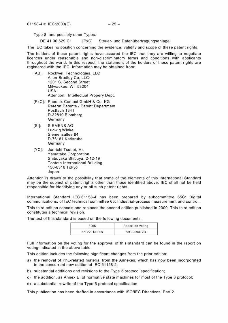
61158-4 IEC:2003(E) – 25 –
Type 8 and possibly other Types: DE 41 00 629 C1 [PxC] Steuer- und Datenübertragungsanlage
The IEC takes no position concerning the evidence, validity and scope of these patent rights. The holders of these patent rights have assured the IEC that they are willing to negotiate licences under reasonable and non-discriminatory terms and conditions with applicants throughout the world. In this respect, the statement of the holders of these patent rights are registered with the IEC. Information may be obtained from:
[AB]: Rockwell Technologies, LLC Allen-Bradley Co, LLC 1201 S. Second Street Milwaukee, WI 53204 USA Attention: Intellectual Propery Dept.
[PxC]: Phoenix Contact GmbH & Co. KG Referat Patente / Patent Department Postfach 1341 D-32819 Blomberg Germany
[SI]: SIEMENS AG Ludwig Winkel Siemensallee 84 D-76181 Karlsruhe Germany
[YC]: Jun-ichi Tsuboi, Mr. Yamatake Corporation Shibuyaku Shibuya, 2-12-19 Tohtate International Building 150-8316 Tokyo Japan
Attention is drawn to the possibility that some of the elements of this International Standard may be the subject of patent rights other than those identified above. IEC shall not be held responsible for identifying any or all such patent rights.
International Standard IEC 61158-4 has been prepared by subcommittee 65C: Digital communications, of IEC technical committee 65: Industrial-process measurement and control. This third edition cancels and replaces the second edition published in 2000. This third edition constitutes a technical revision. The text of this standard is based on the following documents:
FDIS Report on voting
65C/291/FDIS 65C/299/RVD
Full information on the voting for the approval of this standard can be found in the report on voting indicated in the above table. This edition includes the following significant changes from the prior edition: a) the removal of PhL-related material from the Annexes, which has now been incorporated
in the concurrent new edition of IEC 61158-2; b) substantial additions and revisions to the Type 3 protocol specification; c) the addition, as Annex E, of normative state machines for most of the Type 3 protocol; d) a substantial rewrite of the Type 6 protocol specification.
This publication has been drafted in accordance with ISO/IEC Directives, Part 2.

– 26 – 61158-4 IEC:2003(E)
The committee has decided that the contents of this publication will remain unchanged until 2007. At this date, the publication will be
• reconfirmed; • withdrawn; • replaced by a revised edition, or • amended.
IEC 61158 consists of the following parts, under the general title Digital data communications for measurement and control — Fieldbus for use in industrial control systems: Part 1: Overview and guidance for the IEC 61158 series Part 2: Physical Layer specification and service definition Part 3: Data Link Service definition Part 4: Data Link Protocol specification Part 5: Application Layer Service definition Part 6: Application Layer protocol specification

61158-4 IEC:2003(E) – 27 –
0 Introduction
0.1 General
This part of IEC 61158 is one of a series produced to facilitate the interconnection of automation system components. It is related to other standards in the set as defined by the “three-layer” Fieldbus Reference Model, which is based in part on the Basic Reference Model for Open Systems Interconnection. Both Reference Models subdivide the area of standardization for interconnection into a series of layers of specification, each of manageable size.
The Data Link Protocol provides the Data Link Service by making use of the services available from the Physical Layer. The relationship between the International Standards for Fieldbus Data Link Service, Fieldbus Data Link Protocol, Fieldbus Physical Service and Systems Management is illustrated in Figure 1.
NOTE Systems Management, as used in this standard, is a local mechanism for managing the layer protocols.
Application Layer
Data Link Layer
Physical Layer S
ys t
ems
Man
ag e
men
t
Medium
Figure 1 – Relationship of IEC 61158-4 to other fieldbus layers and to users of the fieldbus Data Link service
The primary aim of this standard is to provide a set of rules for communication expressed in terms of the procedures to be carried out by peer Data Link entities (DLEs) at the time of communication. These rules for communication are intended to provide a sound basis for development in order to serve a variety of purposes:
a) as a guide for implementors and designers;
b) for use in the testing and procurement of equipment;
c) as part of an agreement for the admittance of systems into the open systems environment;
d) as a refinement to the understanding of time-critical communications within OSI.
This standard is concerned, in particular, with the communication and interworking of sensors, effectors and other automation devices. By using this standard together with other standards positioned within the OSI or Fieldbus Reference Models, otherwise incompatible systems may work together in any combination.
0.2 Nomenclature for references within this standard
Clauses, including annexes, can be referenced in their entirety, including any subordinate subclauses, as “clause N” or “Annex N”, where N is the number of the clause or letter of the annex.
Data Link Management services
Data Link services

– 28 – 61158-4 IEC:2003(E)
Subclauses can be referenced in their entirety, including any subordinate subclauses, as “N.M” or “N.M.P” and so forth, depending on the level of the subclause, where N is the number of the subclause or letter of the annex, and M, P and so forth represent the successive levels of subclause up to and including the subclause of interest.
When a clause or subclause contains one or more subordinate subclauses, the text between the clause or subclause heading and its first subordinate subclause can be referenced in its entirety as “N.0” or “N.M.0” or “N.M.P.0” and so forth, where N, M and P are as above. Stated differently, a reference ending with “.0” designates the text and figures between a clause or subclause header and its first subordinate subclause.
NOTE This nomenclature provides a means of referencing text in hanging clauses. Such clauses existed in earlier editions of this standard. Some of those hanging clauses are maintained in this edition to minimize the disruption to existing national and multi-national standards and consortia documents which reference that prior subclause numbering.

61158-4 IEC:2003(E) – 29 –
DIGITAL DATA COMMUNICATIONS FOR MEASUREMENT AND CONTROL – FIELDBUS FOR USE IN INDUSTRIAL CONTROL SYSTEMS –
Part 4: Data Link protocol specification
1 Scope and object
1.1 Overview
The Fieldbus Data Link Layer provides basic time-critical messaging communications between devices in an automation environment.
The purpose of this part of IEC 61158 is to define eight distinct and non-interoperable fieldbus Data Link protocols. Each protocol defined in this part of this standard is most closely related to, and lies within the field of application of, the corresponding services of IEC 61158-3, the fieldbus Data Link Service Definition. The eight distinct protocols are the following:
Type 1 — A DL-protocol for the Type 1 DL-service. The maximum system size is 56k links of 232 nodes, each with 240 DLSAP-addresses and related peer and publisher DLCEPs, plus another 768 link-wide group DL-addresses per link, plus another 256 DLSAP-addresses and 2816 peer and publisher DLCEPs per link which can be allocated among the link’s nodes, plus 227 group DL-addresses for the extended link. Fewer links or nodes permits an increase in the number of DLSAP-addresses and related DLCEPs.
Type 2 — A DL-protocol for the Type 2 DL-service. The maximum system size is an unlimited number of links of 99 nodes, each with 255 DLSAP-addresses. Each link has a maximum of 224 related peer and publisher DLCEPs.
Type 3 — A DL-protocol for the Type 3 DL-service. The maximum system size is an unlimited number of links of 127 nodes, each with 66 DLSAP-addresses.
Type 4 — A DL-protocol for the Type 4 DL-service. The maximum system size is a single link with a virtually unlimited number of nodes, each with 256 DLSAP-addresses connected to a single DLS-user.
Type 5 — A second DL-protocol for the Type 1 DL-service. The maximum system size for this protocol is 240 links of 240 nodes, each with 216 DLSAP-addresses and related peer and publisher DLCEPs, plus another 227 link-wide group DL-addresses per link, plus 227 group DL-addresses for the extended link. A normative specification of this protocol was not avail-able at the time of compilation of this edition.
Type 6 — A DL-protocol for the Type 6 DL-service. The maximum system size is a six-deep hierarchy of bridges for a total of 2406 links, each of 240 nodes, where each node has 240 DLSAP-addresses and over 60k related peer and publisher DLCEPs, plus 16 group-DL-addresses and 4k peer and publisher DLCEPs per link which can be allocated among the link’s nodes, plus a very large number of group DL-addresses for each hierarchical subtree of the extended link.
Type 7 — A DL-protocol for the Type 7 DL-service. The maximum system size is 126 links of 256 nodes, each with 16 DLSAP-addresses and 16 group DL-addresses, plus another 28k DLSAP-addresses and related peer and publisher DLCEPs per link which can be allocated among the link’s nodes, plus another 28k link-wide group DL-addresses per link, plus 223 group DL-addresses for the extended link.

– 30 – 61158-4 IEC:2003(E)
Type 8 — A DL-protocol for the Type 8 DL-service. The maximum system size is 1 link of 256 nodes with preconfigured DLCEPs.
1.2 Specifications
This standard specifies:
a) procedures for eight distinct and largely-incompatible protocols for the timely transfer of data and control information from one data-link user entity to a peer user entity, and among the data-link entities forming the distributed data-link service provider;
b) the structure of the fieldbus Data Link (DL) Protocol Data Units used for the transfer of data and control information by each of those eight protocols, and their representation as Physical Interface Data Units.
NOTE Throughout IEC 61158-4, gray boxes have been used in the tables to indicate that the specified field is not a conceptual part of the specific DLPDU.
1.2.1 Type 1: Additional characteristics
This protocol provides communication opportunities to all participating data-link entities
a) in a cyclic asynchronous manner, sequentially to each of those data-link entities, and b) in a synchronous manner, either cyclically or acyclically, according to a pre-established
schedule.
The specified protocol also provides means of changing the set of participating data-link entities and of modifying the set of scheduled communications opportunities. When the set of scheduled communications opportunities is null, the distribution of communication opportunities to the participating data-link entities is completely asynchronous.
Thus this protocol can be characterized as one which provides access asynchronously but with a synchronous overlay.
1.2.2 Type 2: Additional characteristics
This protocol provides communication opportunities to all participating data-link entities, sequentially and in a cyclic synchronous manner. Foreground scheduled access is available for time-critical activities together with background unscheduled access for less critical activities.
Deterministic and synchronized transfers can be provided at cyclic intervals up to 1 ms and device separations of 25 km. This performance is adjustable dynamically and on-line by re-configuring the parameters of the local link whilst normal operation continues. By similar means, DL-connections and new devices may be added or removed during normal operation.
This protocol provides means to maintain clock synchronization across an extended link with a precision better than 10 µs.
This protocol optimizes each access opportunity by concatenating multiple DLSDUs and associated DLPCI into a single DLPDU, thereby improving data transfer efficiency for data-link entities that actively source multiple streams of data.

61158-4 IEC:2003(E) – 31 –
1.2.3 Type 3: Additional characteristics
This protocol provides communication opportunities to a pre-selected “master” subset of data-link entities in a cyclic asynchronous manner, sequentially to each of those data-link entities. Other data-link entities communicate only as permitted and delegated by those master data-link entities.
For a given master, its communications with other data-link entities can be cyclic, or acyclic with prioritized access, or a combination of the two.
This protocol provides a means of sharing the available communication resources in a fair manner. There are provisions for time synchronization and for isochronous operation.
1.2.4 Type 4: Additional characteristics
This protocol provides a means of connecting devices through a partial mesh network, such that most failures of an interconnection between two devices can be circumvented. In common practice the devices are interconnected in a non-redundant hierarchical manner reflecting application needs
1.2.5 Type 5: Additional characteristics
This protocol is an adaptation of the Type 1 protocol for a PhL consisting of high-speed counter-rotating prioritized buffer insertion rings. It provides the identical Type 1 DL-service. The Type 1 and Type 5 protocols are interconnectable through bridges, seamlessly providing the entire Type 1 DL-service. These bridges forward Type 1 DLPDUs between Type 1 and Type 5 links without change, providing end-to-end error detection through a frame check sequence appended by the originating DLE.
This protocol is anticipated to be most appropriate for connecting complex control systems which must exchange large amounts of information. It provides means to maintain clock synchronization across an extended link with a precision better than 100 ns.
A normative specification of this protocol was not available at the time of compilation of this edition.
1.2.6 Type 6: Additional characteristics
This protocol provides a means of interchanging fixed-length input/output data and variable-length segmented messages between peer devices interconnected in a multidrop bus topology. The exchange of input/output data and selected messaging data is totally synchronous by configuration, and each exchange is unaffected by other traffic.
1.2.7 Type 7: Additional characteristics
This protocol provides communication opportunities to all participating data-link entities
a) in a synchronously-starting cyclic manner, according to a pre-established schedule, and b) in a cyclic or acyclic asynchronous manner, as requested each cycle by each of those
data-link entities.
Thus this protocol can be characterized as one which provides cyclic and acyclic access asynchronously but with a synchronous restart of each cycle.

– 32 – 61158-4 IEC:2003(E)
1.2.8 Type 8: Additional characteristics
This protocol provides a highly-optimized means of interchanging fixed-length input/output data and variable-length segmented messages between a single master device and a set of slave devices interconnected in a loop (ring) topology. The exchange of input/output data is totally synchronous by configuration, and is unaffected by the messaging traffic.
Devices are addressed implicitly by their position on the loop. The determination of the number, identity and characteristics of each device can be configured, or can be detected automatically at start-up.
1.3 Procedures
The procedures are defined in terms of
a) the interactions between peer DL-entities (DLEs) through the exchange of fieldbus Data Link Protocol Data Units;
b) the interactions between a DL-service (DLS) provider and a DLS-user in the same system through the exchange of DLS primitives;
c) the interactions between a DLS-provider and a Physical Service provider in the same system through the exchange of Ph-service primitives.
1.4 Applicability
These procedures are applicable to instances of communication between systems which support time-critical communications services within the Data Link layer of the OSI or Fieldbus Reference Models, and which require the ability to interconnect in an open systems interconnection environment.
Profiles provide a simple multi-attribute means of summarizing an implementation’s capabilities, and thus its applicability to various time-critical communications needs. Clause 12 specifies profiles for the Type 1 fieldbus DL-protocol.
1.5 Conformance
This standard also specifies conformance requirements for systems implementing these procedures. This part of this standard does not contain tests to demonstrate compliance with such requirements.
The supplier of a Type 1 protocol implementation which is claimed to conform to this standard should complete a copy of the PICS proforma (see clause 13), including the information necessary to identify both the supplier and the implementation.
2 Normative references
The following referenced documents are indispensable for the application of this document. For dated references, only the edition cited applies. For undated references, the latest edition of the referenced document (including any amendments) applies.
IEC 61131-3:1993, Programmable controllers – Part 3: Programming languages
IEC 61158, Digital data communications for measurement and control – Fieldbus for use in industrial control systems
IEC 61158-2:2003, Part 2: Digital data communications for measurement and control – Fieldbus for use in industrial control systems — Physical layer specification and service definition
IEC 61158-3:2003, Part 3: Digital data communications for measurement and control – Fieldbus for use in industrial control systems — Data link service definition

61158-4 IEC:2003(E) – 33 –
IEC 61158-5:2003, Part 5: Digital data communications for measurement and control – Fieldbus for use in industrial control systems — Application layer service definition
IEC 61158-6:2003, Part 6: Digital data communications for measurement and control – Fieldbus for use in industrial control systems — Application layer protocol specification
ISO/IEC 7498 (all parts), Information technology – Open Systems Interconnection – Basic Reference Model
ISO/IEC 7498-1:1994, Information technology – Open Systems Interconnection – Basic Reference Model — Basic Reference Model: The Basic Model
ISO/IEC 7498-3:1997, Information technology – Open Systems Interconnection – Basic Reference Model — Basic Reference Model: Naming and addressing
ISO/IEC 8886:1996, Information technology – Open Systems Interconnection – Data link service definition for Open Systems Interconnection
ISO/IEC 10038:1993, Information technology – Telecommunications and information exchange between systems – Local area networks – Media Access Control (MAC) bridges
ISO/IEC 10731:1994, Information technology – Open Systems Interconnection – Basic Reference Model – Conventions for the definition of OSI services
CENELEC EN 50170, General purpose field communication system
CENELEC EN 50170-3-1:1996, General purpose field communication system — Data link layer definitions
CENELEC EN 50170-3-7:1996, General purpose field communication system — Network management
3 Terms and definitions
For the purposes of this document, the following terms and definitions apply.
3.1 Reference model terms and definitions
This standard is based in part on the concepts developed in ISO/IEC 7498-1 and ISO/IEC 7498-3, and makes use of the following terms defined therein.
3.1.1 called-DL-address [7498-3]
3.1.2 calling-DL-address [7498-3]
3.1.3 centralized multi-end-point-connection [7498-1]
3.1.4 correspondent (N)-entities correspondent DL-entities (N=2) correspondent Ph-entities (N=1)
[7498-1]
3.1.5 demultiplexing [7498-1]
3.1.6 DL-address [7498-3]
3.1.7 DL-address-mapping [7498-1]
3.1.8 DL-connection [7498-1]
3.1.9 DL-connection-end-point [7498-1]
3.1.10 DL-connection-end-point-identifier [7498-1]
3.1.11 DL-connection-mode transmission [7498-1]