Embed Size (px)
Citation preview
UNCLASSIFIED
UNCLASSIFIED
Notice: NETPDTC is no longer responsible for the content
accuracy of the NRTCs.
For content issues, contact the servicing Center of
Excellence: Center for Surface Combat Systems; (540) 653-
4639 or DSN: 249.
DISTRIBUTION STATEMENT A: Approved for public release;
distribution is unlimited.
NONRESIDENT
TRAINING
COURSE
January 2011
Interior
Communications
Electrician,
Volume 2 NAVEDTRA 14121A
S/N 0505-LP-110-7077

UNCLASSIFIED
UNCLASSIFIED
DISTRIBUTION STATEMENT A: Approved for public release; distribution is unlimited.
Although the words “he,” “him,” and “his” are
used sparingly in this course to enhance
communication, they are not intended to be
gender driven or to affront or discriminate
against anyone.

UNCLASSIFIED
i
UNCLASSIFIED
PREFACE
By enrolling in this self-study course, you have demonstrated a desire to improve
yourself and the Navy. Remember, however, this self-study course is only one part of the
total Navy training program. Practical experience, schools, selected reading, and your
desire to succeed are also necessary to successfully round out a fully meaningful training
program.
THE COURSE: This self-study course is organized into subject matter areas, each
containing learning objectives to help you determine what you should learn along with
text and illustrations to help you understand the information. The subject matter reflects
day-to-day requirements and experiences of personnel in the rating or skill area. It also
reflects guidance provided by Enlisted Community Managers (ECMs) and other senior
personnel, technical references, instructions, etc., and either the occupational or naval
standards, which are listed in the Manual of Navy Enlisted Manpower Personnel
Classifications and Occupational Standards, NAVPERS 18068.
THE QUESTIONS: The questions that appear in this course are designed to help you
understand the material in the text.
VALUE: In completing this course, you will improve your military and professional
knowledge. Importantly, it can also help you study for the Navy-wide advancement in
rate examination. An additional important feature of this course is its reference to useful
information in other publications. The well-prepared Sailor will take the time to look up
the additional information.
2011 Edition
Published by
Center for Surface Combat Systems (CSCS)
NAVSUP Logistics Tracking Number
0504-LP-110-7077

UNCLASSIFIED
ii
UNCLASSIFIED
Sailor’s Creed
“I am a United States Sailor.
I will support and defend the
Constitution of the United States of
America and I will obey the orders of those
appointed over me.
I represent the fighting spirit of the Navy
and those who have gone before me to
defend freedom and democracy around the
world.
I proudly serve my country’s Navy combat
team with honor, courage and commitment.
I am committed to excellence and the fair
treatment of all.”

UNCLASSIFIED
iii
UNCLASSIFIED
TABLE OF CONTENTS
CHAPTER PAGE
1. Synchros, Synchro Signal Amplifies and Wind Indicating Systems 1-1
2. Aviation Equipment 2-1
3. Ship’s Entertainment Systems 3-1
4. Technical Administration 4-1
5. Quality Assurance 5-1
6. Ship's Drawings and Diagrams 6-1
7. Maintenance 7-1
APPENDIX
A Glossary A-1
B References B-1
Course Assignments follow Appendix B

UNCLASSIFIED
iv
UNCLASSIFIED
STUDENT FEEDBACK AND QUESTIONS
We value your suggestions, questions, and criticisms on our courses. If you would like to
communicate with us regarding this course, we encourage you, if possible, to use e-mail
or to post your comments on the Interior Communications Electrician Community of
Practice (COP) page located at https://wwwa.nko.navy.mil/portal/home/. If you write or
fax, please use a copy of the Student Comment form that follows this page.
For subject matter questions:
E-mail: [email protected]
Phone: Comm: 540-653-4639
DSN: 249-4639
Address:
COMMANDING OFFICER
Center for Surface Combat Systems
5395 First St
Dahlgren, VA 22448-5200

UNCLASSIFIED
v
UNCLASSIFIED
Student Comments
Course Title: Interior Communications Electrician, Volume 2
NAVEDTRA: 14121A Date: ____________
We need some information about you:
Rate/Rank and Name: _____________ Command/Unit: ________
Street Address: ________________ City: _____________ State/FPO: _____ Zip _____
Your comments, suggestions, etc.:
Privacy Act Statement: Under authority of Title 5, USC 301, information regarding your military status is
requested in processing your comments and in preparing a reply. This information will not be divulged
without written authorization to anyone other than those within DOD for official use in determining
performance.

UNCLASSIFIED
vi
UNCLASSIFIED
This page left intentionally blank.

Interior Communications Electrician, Volume 2 NAVEDTRA 14121A
UNCLASSIFIED
1 SYNCHROS, SYNCHRO SIGNAL AMPLIFIERS, AND WIND INDICATING SYSTEMS
Upon completion of this chapter, you should be able to do the following:
• Describe the types of wind direction and speed indicating systems. • Identify the major components of wind and speed systems. • Describe the purpose and operation of the major components. • Describe synchros and the different types of synchros. • Describe the synchro signal amplifier and its principles of operation.
1.0.0 INTRODUCTION This chapter will introduce the most common synchros, synchro signal amplifiers, and wind indicating systems found aboard U.S. Navy ships.
1-1 UNCLASSIFIED
Interior Communications Electrician, Volume 2 NAVEDTRA 14121A
UNCLASSIFIED
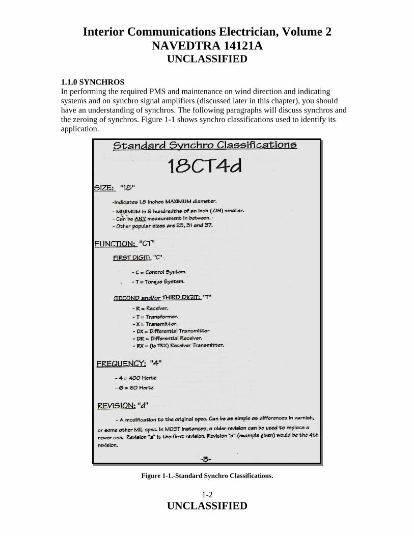
1.1.0 SYNCHROS In performing the required PMS and maintenance on wind direction and indicating systems and on synchro signal amplifiers (discussed later in this chapter), you should have an understanding of synchros. The following paragraphs will discuss synchros and the zeroing of synchros. Figure 1-1 shows synchro classifications used to identify its application.
Figure 1-1.-Standard Synchro Classifications.
1-2 UNCLASSIFIED

Interior Communications Electrician, Volume 2 NAVEDTRA 14121A
UNCLASSIFIED
Synchros (fig. 1-1) are used primarily for the rapid and accurate transmission of information between equipment and stations. Synchros are seldom used singly. They work in teams, and when two or more synchros are interconnected to work together, they form a synchro system. Such a system may, depending on the types and arrangement of its components, be put to various uses. Figure 1-2 shows a simple synchro system that can be used to transmit different types of data.
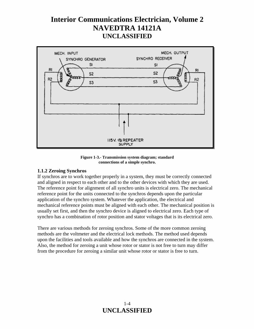
Figure 1-2.-A simple synchro system. 1.1.1 Standard Synchro Connections In systems in which a great many synchro units are used, it is necessary to have a closely defined set of standard connections to avoid confusion. The conventional connection is for counterclockwise rotation for an increasing reading. The standard connections of a simple synchro transmission system consisting of a synchro transmitter and receiver is shown in figure 1-3. The R1 transmitter and receiver leads connect to one side of the 115-volt ac supply line. The R2 transmitter and receiver leads connect to the other side of the line. The stator leads of both the transmitter and receiver connect lead for lead; that is, S1 connects to S1, S2 to S2, and S3 to S3. Thus, when sending an increasing reading over the transmission system, the rotor of the synchro receiver will turn in a counterclockwise direction. When it is desired, the shaft of the synchro receiver turns clockwise for an increasing reading. The R1 and R2 transmitter and receiver leads connect as before. The S1 transmitter lead connects to the S3 receiver lead, and the S2 transmitter lead to the S1 receiver lead.
1-3 UNCLASSIFIED
Interior Communications Electrician, Volume 2 NAVEDTRA 14121A
UNCLASSIFIED
Figure 1-3.- Transmission system diagram; standard connections of a simple synchro.
1.1.2 Zeroing Synchros If synchros are to work together properly in a system, they must be correctly connected and aligned in respect to each other and to the other devices with which they are used. The reference point for alignment of all synchro units is electrical zero. The mechanical reference point for the units connected to the synchros depends upon the particular application of the synchro system. Whatever the application, the electrical and mechanical reference points must be aligned with each other. The mechanical position is usually set first, and then the synchro device is aligned to electrical zero. Each type of synchro has a combination of rotor position and stator voltages that is its electrical zero. There are various methods for zeroing synchros. Some of the more common zeroing methods are the voltmeter and the electrical lock methods. The method used depends upon the facilities and tools available and how the synchros are connected in the system. Also, the method for zeroing a unit whose rotor or stator is not free to turn may differ from the procedure for zeroing a similar unit whose rotor or stator is free to turn.
1-4 UNCLASSIFIED

Interior Communications Electrician, Volume 2 NAVEDTRA 14121A
UNCLASSIFIED
Voltmeter Method The most accurate method of zeroing a synchro is the ac voltmeter method. The procedure and the test circuit configuration for this method vary somewhat, depending upon which type of synchro is being zeroed. Transmitters and receivers, differentials, and control transformers each require different test-circuit configurations. For the ac voltmeter method to be as accurate as possible, an electronic or precision voltmeter having a 0- to 250-volt and a 0- to 5-volt range should be used. On the low scale, this meter can also measure voltages as low as 0.1 volt. Many synchro units are marked in such a manner that the coarse setting may be approximated physically by aligning two marks on the synchro. On standard synchros, this setting is indicated by an arrow stamped on the frame and a line marked on the shaft, as shown in figure 1-4. The fine setting is where the synchro is precisely set on 0O.
Figure 1-4.- Coarse electrical zero markings.
1-5 UNCLASSIFIED

Interior Communications Electrician, Volume 2 NAVEDTRA 14121A
UNCLASSIFIED
Zeroing Transmitters and Receivers (Voltmeter Method) A synchro transmitter, CX or TX, is zeroed if electrical zero voltages exist when the device whose position the CX or TX transmits is set to its mechanical reference position. A synchro receiver, TR, is zeroed if, when electrical zero voltages exist, the device actuated by the receiver assumes its mechanical reference position. In a receiver or other unit having a rotatable stator, the zero position is the same, with the added provision that the unit to which the stator is geared is set to its reference position. In the electrical zero position, the axes of the rotor coil and the S2 coil are at zero displacement and the voltages measured between terminals S1 and S3 will be the minimum. The voltages from S2 to S1 and from S2 to S3 are in phase with the excitation voltage from R1 to R2.
Figure 1-5.- Synchro Zeroing Method.
1-6 UNCLASSIFIED
Interior Communications Electrician, Volume 2 NAVEDTRA 14121A
UNCLASSIFIED
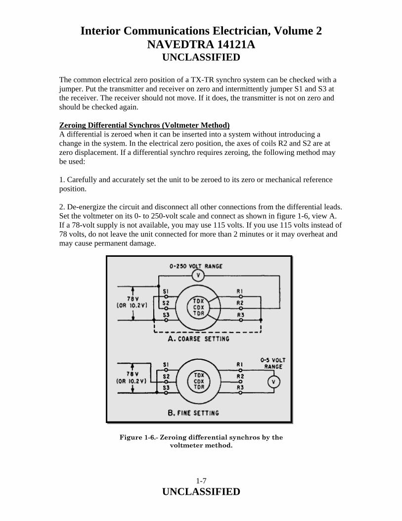
The common electrical zero position of a TX-TR synchro system can be checked with a jumper. Put the transmitter and receiver on zero and intermittently jumper S1 and S3 at the receiver. The receiver should not move. If it does, the transmitter is not on zero and should be checked again. Zeroing Differential Synchros (Voltmeter Method) A differential is zeroed when it can be inserted into a system without introducing a change in the system. In the electrical zero position, the axes of coils R2 and S2 are at zero displacement. If a differential synchro requires zeroing, the following method may be used: 1. Carefully and accurately set the unit to be zeroed to its zero or mechanical reference position. 2. De-energize the circuit and disconnect all other connections from the differential leads. Set the voltmeter on its 0- to 250-volt scale and connect as shown in figure 1-6, view A. If a 78-volt supply is not available, you may use 115 volts. If you use 115 volts instead of 78 volts, do not leave the unit connected for more than 2 minutes or it may overheat and may cause permanent damage. Figure 1-6.- Zeroing differential synchros by the
voltmeter method.
1-7 UNCLASSIFIED

Interior Communications Electrician, Volume 2 NAVEDTRA 14121A
UNCLASSIFIED
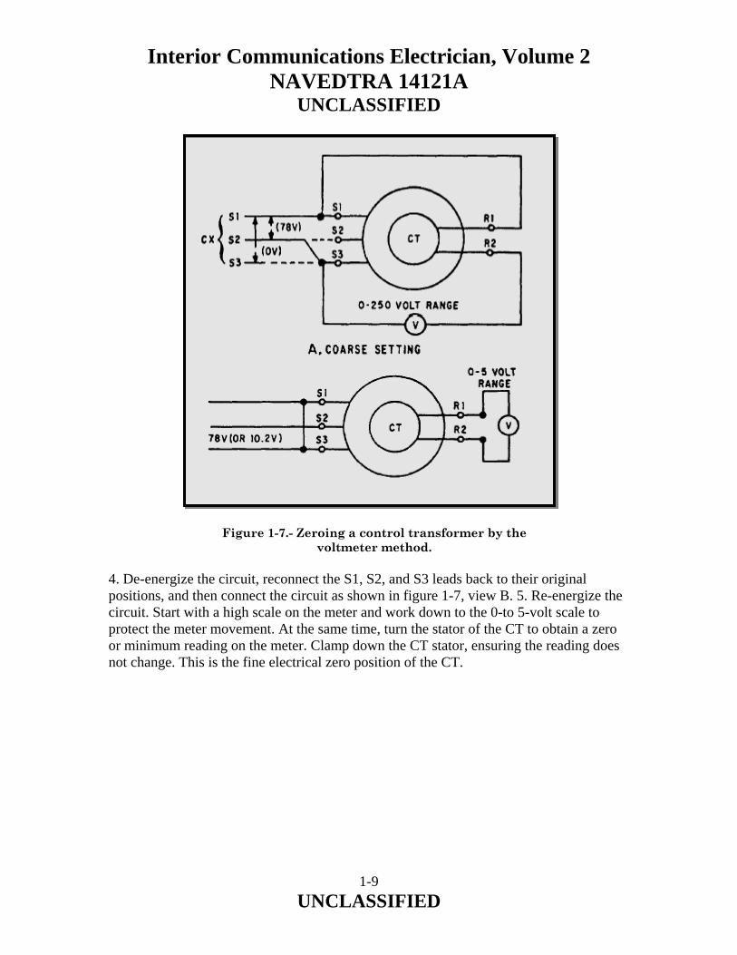
3. Energize the circuit, unclamp the differential’s stator, and turn it until the meter reads minimum. The differential is now approximately on electrical zero. De-energize the circuit and reconnect it as shown in figure 1-6, view B. 4. Re-energize the circuit. Start with a high scale on the meter and work down to the 0- to 5-volt scale to protect the meter movement. At the same time, turn the differential transmitter until a zero or null (minimum voltage) reading is obtained. Clamp the differential stator in this position, ensuring the voltage reading does not change, de-energize, and connect all leads for normal operation. This is the fine electrical zero position of the differential. Zeroing a Control Transformer (Voltmeter Method) Two conditions must exist for a control transformer (CT) to be on electrical zero. First, its rotor voltage must be at a minimum when electrical zero voltages are applied to its stator. Second, turning the shaft of the CT slightly counterclockwise produces a voltage across its rotor in phase with the rotor voltage of the CX or TX, supplying excitation to its stator. Electrical zero voltages, for the stator only, are the same as for transmitters and receivers. To zero a CT by the voltmeter method, use the following procedure: 1. Set the mechanism that drives the CT rotor to zero or to its reference position. Also, set the transmitter that is connected to the CT to zero or its reference position. 2. Check to ensure there is zero volts between S1 and S3 and 78 volts between S2 and S3. If these voltages cannot be obtained, it will be necessary to re-zero the transmitter. NOTE: If 78 volts from the transmitter cannot be used and an autotransformer is not available, use a 115-volt source. The CT should not be energized for more than 2 minutes in this condition because it will overheat and may cause permanent damage. 3. De-energize the circuit and connect the circuit as shown in figure 1-7, view A. To obtain the 78 volts required to zero the CT, leave the S1 lead on, disconnect the S3 lead on the CT, and put the S2 lead (from CX) on S3. This is necessary since 78 volts exist only between S1 and S2 or S2 and S3 on a properly zeroed CX. Now energize the circuit and turn the stator of the CT to obtain a minimum reading on the 250-volt scale. This is the coarse or approximate zero setting of the CT.
1-8 UNCLASSIFIED
Interior Communications Electrician, Volume 2 NAVEDTRA 14121A
UNCLASSIFIED
Figure 1-7.- Zeroing a control transformer by the
voltmeter method. 4. De-energize the circuit, reconnect the S1, S2, and S3 leads back to their original positions, and then connect the circuit as shown in figure 1-7, view B. 5. Re-energize the circuit. Start with a high scale on the meter and work down to the 0-to 5-volt scale to protect the meter movement. At the same time, turn the stator of the CT to obtain a zero or minimum reading on the meter. Clamp down the CT stator, ensuring the reading does not change. This is the fine electrical zero position of the CT.
1-9 UNCLASSIFIED
Interior Communications Electrician, Volume 2 NAVEDTRA 14121A
UNCLASSIFIED
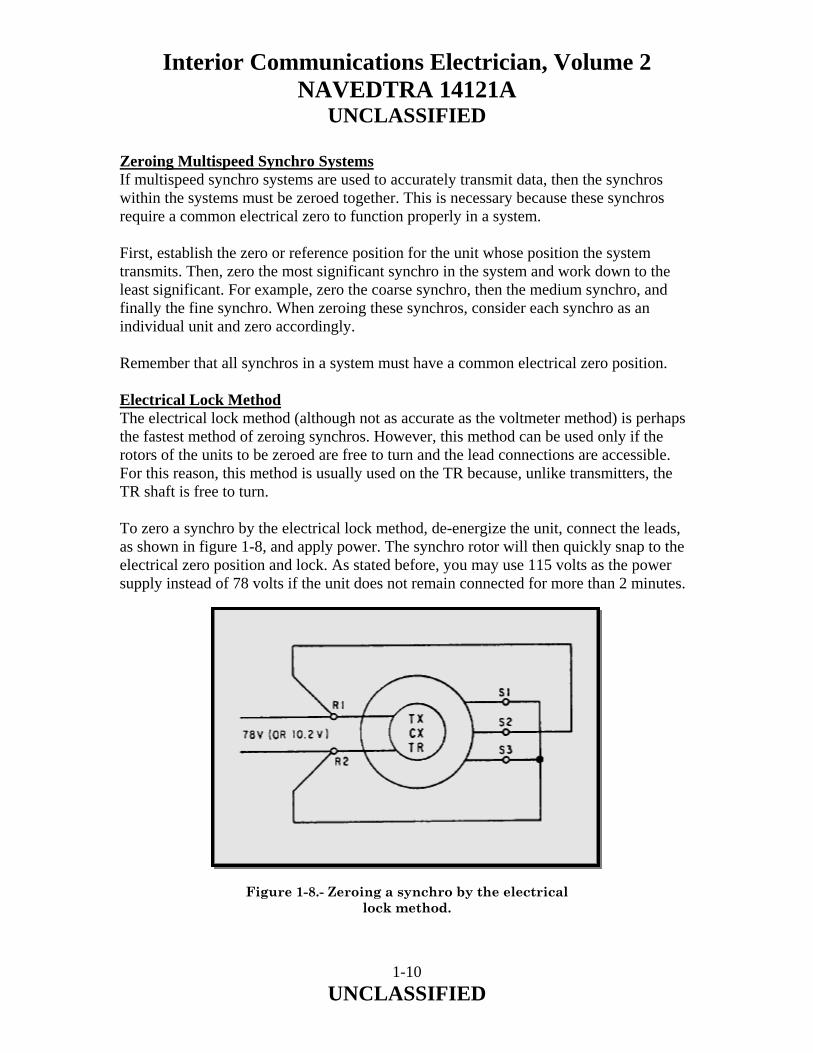
Zeroing Multispeed Synchro Systems If multispeed synchro systems are used to accurately transmit data, then the synchros within the systems must be zeroed together. This is necessary because these synchros require a common electrical zero to function properly in a system. First, establish the zero or reference position for the unit whose position the system transmits. Then, zero the most significant synchro in the system and work down to the least significant. For example, zero the coarse synchro, then the medium synchro, and finally the fine synchro. When zeroing these synchros, consider each synchro as an individual unit and zero accordingly. Remember that all synchros in a system must have a common electrical zero position. Electrical Lock Method The electrical lock method (although not as accurate as the voltmeter method) is perhaps the fastest method of zeroing synchros. However, this method can be used only if the rotors of the units to be zeroed are free to turn and the lead connections are accessible. For this reason, this method is usually used on the TR because, unlike transmitters, the TR shaft is free to turn. To zero a synchro by the electrical lock method, de-energize the unit, connect the leads, as shown in figure 1-8, and apply power. The synchro rotor will then quickly snap to the electrical zero position and lock. As stated before, you may use 115 volts as the power supply instead of 78 volts if the unit does not remain connected for more than 2 minutes.
Figure 1-8.- Zeroing a synchro by the electrical lock method.
1-10 UNCLASSIFIED

Interior Communications Electrician, Volume 2 NAVEDTRA 14121A
UNCLASSIFIED
1.2.0 SYNCHRO MAINTENANCE AND TROUBLESHOOTING Synchro units require careful handling at all times. NEVER force a synchro unit into place, NEVER drill holes into its frame, NEVER use pliers on the threaded shaft, and NEVER use force to mount a gear or dial on the shaft. In maintaining synchros, there are two basic rules to apply: 1. IF IT WORKS, LEAVE IT ALONE. 2. IF IT GOES BAD, REPLACE IT. Shipboard synchro troubleshooting is limited to determining whether the trouble is in the synchro or in the system connections. You can make repairs to the system connections, but if something is wrong with the unit, replace it. 1.3.0 SYNCHRO SIGNAL AMPLIFIER The reason for using synchro signal amplifiers is to reduce the size of synchro transmitters. These smaller synchro transmitters are used in wind indicators and other sensing devices that are more accurate if there is only a small load on their outputs. The input to the amplifier is from a small synchro transmitter or two small transmitters that give a coarse and a fine signal. The input signal controls a small servomotor. This servomotor drives one or more large synchros into a position corresponding to the position of the input synchro. The output from the large synchros is then used as needed to drive several synchro receivers. Synchro signal amplifiers must meet some or all of the following operational requirements:
• Accept a low-current synchro signal, amplify the signal, and use the amplifier signal to drive large capacity synchro transmitters.
• Isolate oscillations in a synchro load that may be reflected from the input signal bus.
• Permit operation of a 60- or 400-Hz synchro load from either a 60-or 400-Hz synchro bus.
• Provide multiple channel output transmission of a single-channel input signal.
• Permit operation of a synchro load independent of the input synchro excitation.
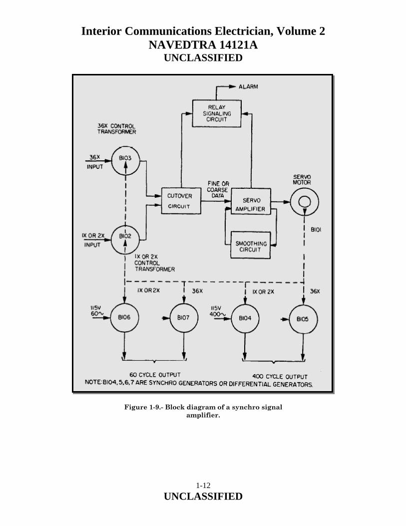
A block diagram of a synchro signal amplifier is shown in figure 1-9.
1-11 UNCLASSIFIED
Interior Communications Electrician, Volume 2 NAVEDTRA 14121A
UNCLASSIFIED
Figure 1-9.- Block diagram of a synchro signal amplifier.
1-12 UNCLASSIFIED

Interior Communications Electrician, Volume 2 NAVEDTRA 14121A
UNCLASSIFIED
1.3.1 General Description E- and F-type synchro signal amplifiers will be discussed in this section of the chapter. The major difference between the two types is that the type E operates with 60-Hz supply and input. The type F operates with 400-Hz supply and input signals. The different supply and input frequencies require that the E- and F-type units use different synchro control transformers, servomotors, synchro capacitors, and amplifiers. Both types have provisions for four output synchros: Normally there are two for 60-Hz and two for 400-Hz transmission. Both types of synchro signal amplifiers are designed to provide for input and output transmission at any of the following combinations of speeds:
• 1 and 36 speed • 1 speed • 36 speed • 2 speed • 2 and 36 speed
NOTE: Other gear combinations can be used for additional speed outputs. The E- and F-type synchro signal amplifiers consist of subassemblies housed in a drip-proof case. These cases are the same on both types of synchro signal amplifiers. The internal subassemblies are similar in design. The only differences are the ones previously covered. The subassembly is easily accessible through a front access door in the case that can be opened by loosening screws in the door. The door has hinges and supporting chains so it can be lowered and used as a service platform for the internal subassembly. An alarm switch, a dial window, four indicator lights, and a double fuse holder are mounted on the front access door. A schematic diagram of the subassembly is provided on the inside of the front access door. Terminal boards on the inside bottom of the case serve as a common junction for connecting the ship’s wiring. Access plates on both sides of the synchro signal amplifier provides for external cabling. Stuffing tubes are mounted to these plates as required at installation, and the external cabling is run through the stuffing tubes.
1-13 UNCLASSIFIED

Interior Communications Electrician, Volume 2 NAVEDTRA 14121A
UNCLASSIFIED
Speed changes from 1 speed to 2 speed and vice versa are made by installing change gears. These gears are not normally furnished with the synchro signal amplifier. Both the E- and F-type units have a dial with two scales, one on each side. One scale is calibrated every degree from 0° to 360° and is driven at 1 speed, when 1 speed is used. The other scale is calibrated 60° either side of zero (300° to 0° and 0° to 60°), and this scale is used when a 2-speed transmission is needed. The dial turns over when changing from 1 speed to 2 speed or vice versa. When either unit is operating from a low 1- or 2-speed input, you must make some minor wiring changes. Connections between the terminals on the plug-in damping unit should be changed from those shown for 1 and 2 speed and 36 speed to those shown for 1 or 2 speed. This connects the normally disconnected low-speed synchro control transformer. These connections also remove the anti-stick-off voltage, which will be discussed later in this chapter. 1.3.2 Principles of Operation The synchro signal amplifier is actually a synchro data repeater. It accepts synchro data from remote transmitters, aligns associated output synchros to electrical correspondence with the remote transmitters, and retransmits the data to other equipment. Synchro transmission is increased by using larger output synchros than the remote transmitter. Since the output synchros are driven to electrical correspondence with the remote transmitters by gearing, a power supply of a different frequency may be used for the output synchros. This gives the synchro signal amplifier another attribute, as a frequency converter. A higher accuracy is obtained from a synchro signal amplifier with a 36-speed input than would be obtained from a l-speed input. By virtue of the 36 speed revolving 36 times the angular distance that the 1 speed would revolve in response to the same reading, a vernier effect is achieved so that a higher accuracy is obtained. 1.3.3 Synchro Operation The synchro transmitter resembles a small bipolar 3-phase motor. The stator is wound with a three-circuit Y-connected winding. The rotor is wound with a single-circuit winding. Electrically, the synchro acts as a transformer; all voltages and currents are single phase. By transformer action, voltages are induced from the rotor (Transformer Primary) into the three elements of the stator winding (Transformer Secondary), the magnitude depending upon the angular position of the rotor.
1-14 UNCLASSIFIED

Interior Communications Electrician, Volume 2 NAVEDTRA 14121A
UNCLASSIFIED
The synchro receiver is constructed essentially the same, both mechanically and electrically, except it is provided with a mechanism for dampening oscillations. Consider the simplest synchro transmission system, where the transmitter and receiver units are connected as shown on figure 1-3. If the receiver rotor were free to turn, it would take a position where induced stator voltages would be equal to the transmitter voltages. Under such a condition there is no current flow. However, if the transmitter rotor was displaced by any angle, the stator voltage balance would be altered and current would flow in the stator windings. This current flow would set up a two-pole torque, turning the receiver rotor to a position where the induced stator voltages would again be equal. Therefore, any motion given to the rotor of one unit would be transmitted to the rotor of the other unit where it is duplicated thereby setting up a system of electrically transmitted mechanical motion. The synchro signal amplifier transmission system depends upon the type of transmitter described in the previous paragraphs, but its receiver is a synchro control transformer. The purpose of the synchro control transformer is to supply, from its rotor terminals, an ac voltage whose magnitude and phase polarity depend upon the position of the rotor and voltages applied to its stator windings. Since its rotor winding is not connected to the ac supply, it does not induce voltage in the stator coils. As a result, the stator current is determined by the high impedance at the windings and it is not affected appreciably by the rotor’s position. Also, there is no detectable current in the rotor and, therefore, no torque striving to turn the rotor. The synchro control transformer rotors cannot on their own accord turn to a position where the induced currents are once again of balanced magnitude. The synchro amplifier cycle of operation must take place to turn the rotor of the synchro control transformer. A synchro amplifier cycle of operation takes place as follows: 1. A change occurs in the remotely transmitted synchro data. 2. The signal received by the synchro control transformers in the mechanical unit is, as an error voltage, amplified and used to operate the servomotor. The servomotor, through gearing, turns the synchro control transformer rotors until the error voltages are zero (or, in the low-speed unit, matched to the stick-off voltage), thereby stopping the turning or follow-up action. 3. Simultaneous with step 2, the servomotor also drives the rotors of the output synchros into alignment with the new input signal.
1-15 UNCLASSIFIED

Interior Communications Electrician, Volume 2 NAVEDTRA 14121A
UNCLASSIFIED
1.3.4 Synchro Connections of a Synchro Amplifier The conventional connection is for counterclockwise rotation for increasing reading-an increasing reading is when the numbers associated with the action being measured are increasing. The five wires of a synchro system are numbered in such a way that the shaft of a normal synchro will turn counterclockwise. When an increasing reading is sent over the wires provided, the synchro is connected as follows:
R1 to terminal block terminal B R2 to terminal block terminal BB S1 to terminal block terminal B1 S2 to terminal block terminal B2 S3 to terminal block terminal B3
When the shaft of the synchro is to be driven clockwise for an increasing reading, the connections to the terminal bus should be as follows:
R1 to terminal block terminal B R2 to terminal block terminal BB S3 to terminal block terminal B1 S2 to terminal block terminal B2 S1 to terminal block terminal B3
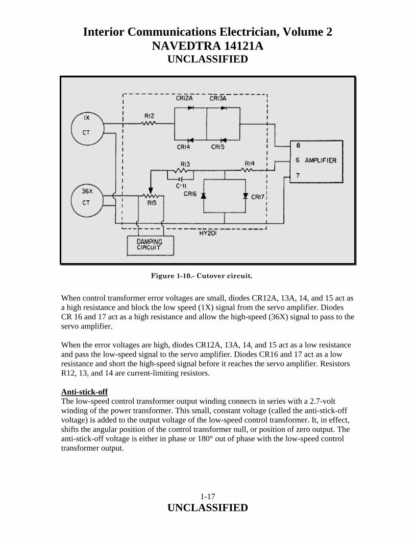
For a synchro control transformer, these connections will apply to the stator, but the rotor connections go to the input of the servo amplifier. 1.3.5 Cutover Circuit The purpose of the cutover circuit is to automatically select the error voltage from either the high (36 speed) or low (1 or 2 speed) synchro control transformer and feed it to the servo-amplifier input terminals. The low-speed control transformer is connected when the error is large (more than 2.5 degrees), and the high-speed control transformer is connected when the error is small (less than 2.5 degrees). The cutover circuit (fig. 1-10) consists of six diodes (CR12A through CR17) and three resistors (R12, R13, and R14). The circuit operates on the principle that diodes, connected back to back, act as nonlinear resistances. When a high voltage appears across the diodes, it appears as a low resistance or a short circuit. When a low voltage appears across the diodes, it appears as a high resistance or an open circuit.
1-16 UNCLASSIFIED
Interior Communications Electrician, Volume 2 NAVEDTRA 14121A
UNCLASSIFIED
Figure 1-10.- Cutover circuit. When control transformer error voltages are small, diodes CR12A, 13A, 14, and 15 act as a high resistance and block the low speed (1X) signal from the servo amplifier. Diodes CR 16 and 17 act as a high resistance and allow the high-speed (36X) signal to pass to the servo amplifier. When the error voltages are high, diodes CR12A, 13A, 14, and 15 act as a low resistance and pass the low-speed signal to the servo amplifier. Diodes CR16 and 17 act as a low resistance and short the high-speed signal before it reaches the servo amplifier. Resistors R12, 13, and 14 are current-limiting resistors. Anti-stick-off The low-speed control transformer output winding connects in series with a 2.7-volt winding of the power transformer. This small, constant voltage (called the anti-stick-off voltage) is added to the output voltage of the low-speed control transformer. It, in effect, shifts the angular position of the control transformer null, or position of zero output. The anti-stick-off voltage is either in phase or 180° out of phase with the low-speed control transformer output.
1-17 UNCLASSIFIED

Interior Communications Electrician, Volume 2 NAVEDTRA 14121A
UNCLASSIFIED
If the high- and low-speed control transformers were set to electrical zero at the same position, there would be a point at 0° and 180° where the error voltage would equal zero. Within 2 1/2° of the 180° point, the 36-speed error signal would drive the servomotor to synchronize the control transformers at the 180° point. The control transformers would also synchronize at the 180° point if the synchro signal amplifier were energized when the control transformers were within 2 1/2° of the 180° point. To remove the chance of synchronization of the control transformers at the 180° point, the low-speed control transformer is rotated 2 1/2° from correspondence with the high-speed control transformer null, or zero, position. An anti-stick-off voltage of constant magnitude and phase is added to the single-speed control transformer output. The resultant voltage is now zero at the 185° point instead of the 180° point. At either side of the 185° point, both the 36-speed and single-speed voltage tend to drive the synchro transmitters toward true zero. Servo Amplifier The servo amplifier is a 10-watt plug-in amplifier with a push-pull output stage that feeds the servomotor control winding. The servo amplifier drives the servomotor, which, in turn, repositions the control transformer rotors to null the error voltage to the servo amplifier. The amplifier has an internal power supply operating from 115 volts ac. It provides 12 volts dc and unfiltered 40 volts dc for the amplifier stages. In addition, the power supply power transformer supplies reference voltage for the servomotor and anti-stick-off voltage. The amplifiers for 60- and 400-Hz units are similar except for the power transformers and capacitors. Gear train oscillation, or hunting, is caused by overshoot as the servo reaches its null. To prevent this, clamping circuits introduce a stabilizing voltage at the amplifier input. This stabilizing voltage is proportional to acceleration or deceleration of the unit. Alarm Circuit The alarm circuits in the synchro signal amplifier monitor the 60- and 400-Hz output excitation, servo excitation, and follow-up error. With all power sources present and a follow-up error of less than 2 1/2°, the four indicator lights on the access door will light. If one of these conditions fails, the appropriate light will go out, indicating the problem area, and an alarm will sound. With the equipment normally energized and the alarm switch in the ON position, the alarm circuit will be open. A loss of any of the three power sources, a follow-up error of more than 2 1/2°, or putting the alarm switch in the OFF position will close the alarm circuit, causing an alarm to sound.
1-18 UNCLASSIFIED

Interior Communications Electrician, Volume 2 NAVEDTRA 14121A
UNCLASSIFIED
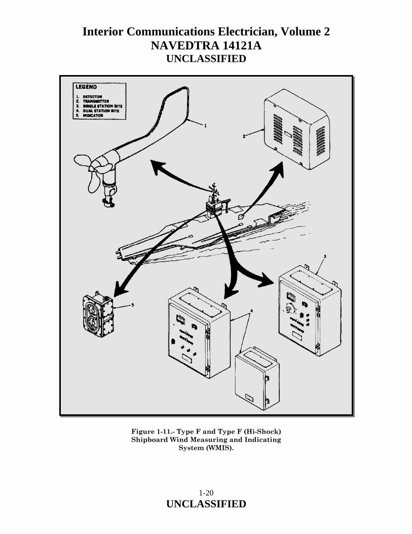
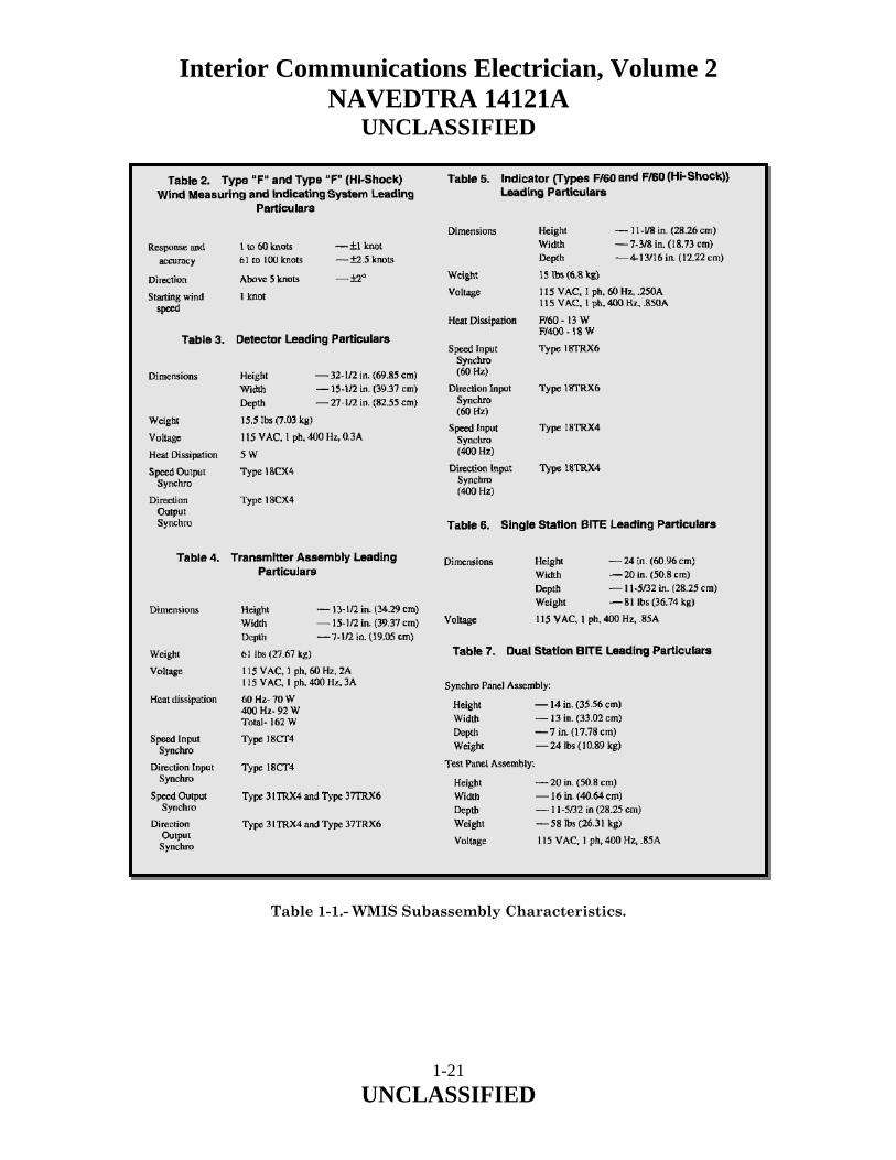
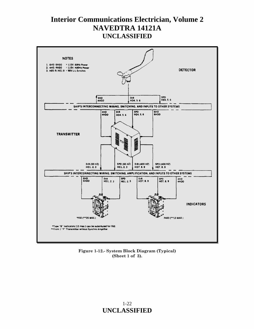
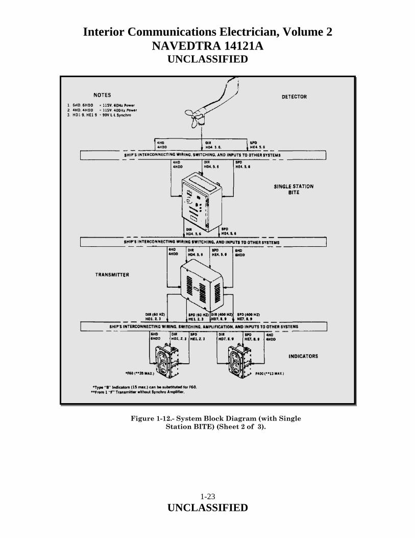
Gear Train The gear train consists of a series of fine pitch, precision, spur gears. They link together the rotors of the two control transformers, four output synchros, and the servomotor. 1.3.6 Maintenance of Synchro Signal Amplifiers The synchro signal amplifier should require little attention in service, there being few parts inside the amplifier unit or the synchros that need lubrication or replacement under normal operating conditions. The alarm circuit takes the place of many routine checks, since failure of the synchro signal amplifier output to follow the input or loss of input excitation automatically completes the alarm circuit. The only routine checks that are required are a monthly check of the alarm circuit and yearly inspection of the gearing. When inspecting the gearing, if dirt is found, clean the gears. If a gear shows excessive wear, replace it. Turn the gears manually, with the equipment deenergized, noting whether the gears mesh smoothly. 1.4.0 WIND INDICATING SYSTEMS The anemometer (wind direction and speed indicator) system, circuits HD and HE, provides instantaneous and continuous indication of wind direction and speed relative to the ship’s heading and speed. Wind direction and speed information is important for combat systems operations, flight operations, and maneuvering. Throughout this chapter we will use the term wind direction and speed indicator systems interchangeably with the term anemometer systems. 1.4.1 Type F and Type F (Hi-Shock) Shipboard Wind Measuring and Indicating Systems The Type "F" and Type "F" (Hi-Shock) Shipboard Wind Measuring and Indicating Systems (WMIS) (Figure 1-11) provide wind direction (in degrees) and wind speed (in knots) data. These Shipboard WMIS consist of the following subassemblies: Refer to Table 1-1 for characteristics applicable to these WMIS subassemblies. Figure 1-12 illustrates typical WMIS installations.
1-19 UNCLASSIFIED
Interior Communications Electrician, Volume 2 NAVEDTRA 14121A
UNCLASSIFIED
Figure 1-11.- Type F and Type F (Hi-Shock) Shipboard Wind Measuring and Indicating
System (WMIS).
1-20 UNCLASSIFIED
Interior Communications Electrician, Volume 2 NAVEDTRA 14121A
UNCLASSIFIED
Table 1-1.- WMIS Subassembly Characteristics.
1-21 UNCLASSIFIED
Interior Communications Electrician, Volume 2 NAVEDTRA 14121A
UNCLASSIFIED
Figure 1-12.- System Block Diagram (Typical) (Sheet 1 of 3).
1-22 UNCLASSIFIED
Interior Communications Electrician, Volume 2 NAVEDTRA 14121A
UNCLASSIFIED
Figure 1-12.- System Block Diagram (with Single Station BITE) (Sheet 2 of 3).
1-23 UNCLASSIFIED
Interior Communications Electrician, Volume 2 NAVEDTRA 14121A
UNCLASSIFIED
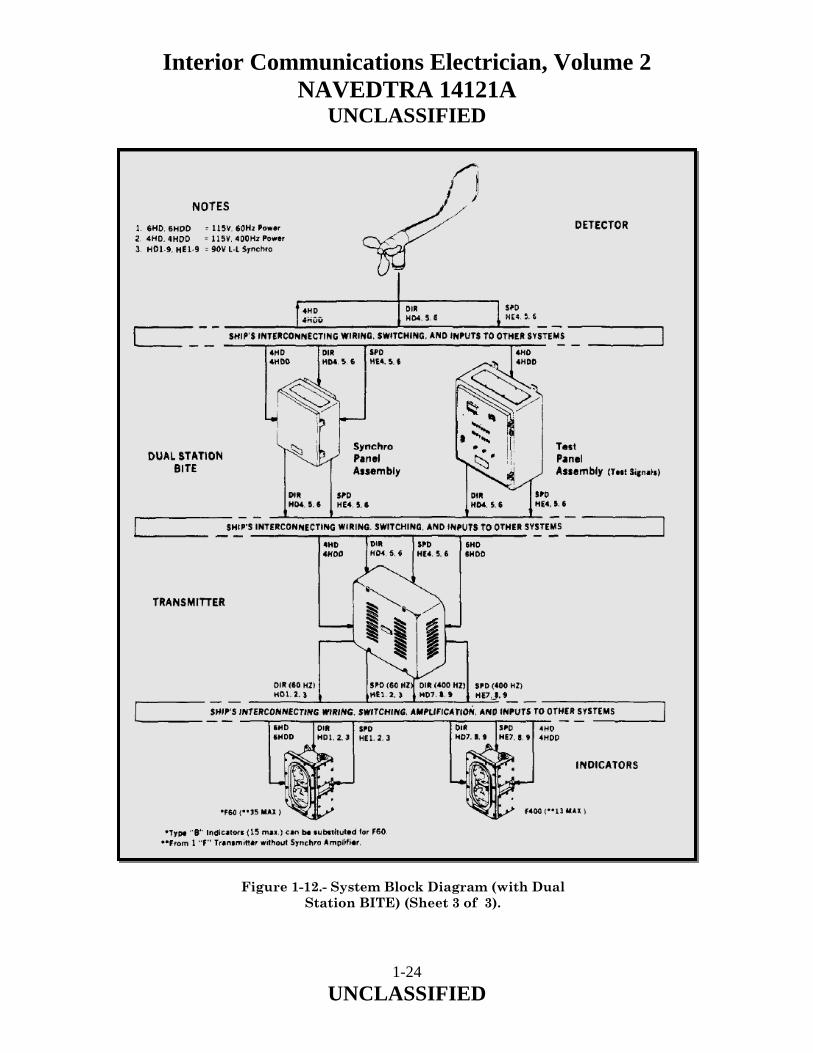
Figure 1-12.- System Block Diagram (with Dual
Station BITE) (Sheet 3 of 3).
1-24 UNCLASSIFIED

Interior Communications Electrician, Volume 2 NAVEDTRA 14121A
UNCLASSIFIED
Wind Direction and Speed Detector Type "F" and Type "F" (Hi-Shock), hereinafter referred to as the detector. The detector is a dual purpose instrument that employs two type 18CX4 synchros that transmit wind direction and speed signals to a transmitter and to other shipboard equipment requiring wind data. Wind Direction and Speed Transmitter Assembly Type "F and for Type "F" (Hi-Shock), hereinafter referred to as the transmitter assembly. The transmitter assembly consists of two plug-in assemblies secured in a common drip-proof case assembly. The plug-in assemblies receive wind direction and wind speed signals from the detector, convert the values, and then transmit these signals to remote indicators and/or other equipment. Wind Direction and Speed Indicator, Type F60 and Type F60 (Hi-Shock), hereinafter referred to as the indicator. The indicator consists of a single wind speed and direction assembly housed in a water tight case. The indicator dials are red-illuminated and display wind direction (in degrees) and wind speed (in knots). Built-In Test Equipment (BITE) (not on all ships) for either Single Station or Dual Station installation. The Single Station consists of a Test and Synchro Panel Assembly. The Dual Station consists of Synchro Panel Assembly and Test Panel Assembly. The BITE is used to generate known test (synchro) signals to check the operation of the WMIS equipment. 1.4.2 Physical Description Detector The detector (Figure 1-13 Type "F", Sheet 1 of 2 and Type "F" (Hi-Shock), Sheet 2 of 2) is a dual purpose instrument that employs two type 18CX4 synchros that transmit wind direction and speed signals to a transmitter and to other shipboard equipment requiring wind data. Direction Synchro Direction synchro (8) is mounted in the support assembly (1) which is coupled to vane assembly (2). Speed synchro (9) is enclosed in the wind speed mechanism assembly (3), mounted opposite the vane. The wind speed mechanism assembly is fastened to a propeller-type rotor (4) which senses wind speed. Electrical connections are made to the speed synchro (9) by collector ring assemblies (10) and brush holder assembly (5). Mounting Assembly Mounting assembly (6) is bolted to support assembly (1) and contains an 11/16-inch diameter hole, three inches deep, for pintle mounting. Mounting bolt (7) acts as a dowel to hold the detector in alignment. In the Type "F" a terminal tube fitting hole with a 3 1/4- inch national pipe thread (13) is provided for attaching a stuffing tube. The Type "F" (Hi-Shock) mounting assembly (6) is internally wired.
1-25 UNCLASSIFIED

Interior Communications Electrician, Volume 2 NAVEDTRA 14121A
UNCLASSIFIED
Figure 1-13.- Wind Direction and Speed Detector
Type “F” (Sheet 1 of 2).
1-26 UNCLASSIFIED

Interior Communications Electrician, Volume 2 NAVEDTRA 14121A
UNCLASSIFIED
Figure 1-13.- Wind Direction and Speed Detector
Type “F” (Hi-Shock) (Sheet 2 of 2).
1-27 UNCLASSIFIED

Interior Communications Electrician, Volume 2 NAVEDTRA 14121A
UNCLASSIFIED
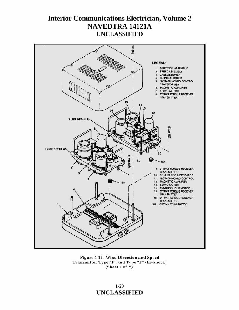
Plug Connector Plug connector (11) is located at the lower end of the support assembly (1) with socket connector (12) located at the top of the mounting assembly (6). They form an electrical connection to permit removal of the detector mechanism without disturbing the incoming wires or the alignment. Transmitter Assembly The transmitter assembly (Figure 1-14) consists of direction assembly (1) and speed assembly (2) which process and amplify wind speed and direction signals. The two plug-in assemblies are secured in a common drip proof case assembly (3) by screws. They are connected electrically through plug connectors on each assembly and mating receptacle connectors in the case assembly. External wiring enters the case assembly through two holes in the bottom. These holes are threaded to accept stuffing tube fittings with one-inch national pipe threads. The incoming wires connect to terminal boards (4) mounted in case assembly (3). Direction Assembly The direction assembly (1, Figure 1-14) is a servo amplifier circuit using a type 18CT4 synchro control transformer (5) as a receiver for angular displacement signals representing vane position. Synchro control transformer (5) output signals are amplified by magnetic amplifier (6) which drives servo motor (7). Servo motor (7) drives the 37TRX6 and 31TRX4 torque receiver transmitters (8 and 9). Speed Assembly The speed assembly (2, Figure 1-14) consists of a servo-amplified circuit and a roller disc-type integrator. A servo amplifier circuit uses a type 18CT4 synchro control transformer (11) as a receiver for signals from the detector representing the rotating speed of the rotor. Synchro control transformer (II) output signals are amplified by magnetic amplifier (12) which drives servo motor (13). Synchronous motor (14) and servo motor (13) drive the roller disc integrator (10), which in turn drives the 37TRX6 and 3ITRX4 torque receiver transmitters (15 and 16).
1-28 UNCLASSIFIED
Interior Communications Electrician, Volume 2 NAVEDTRA 14121A
UNCLASSIFIED
Figure 1-14.- Wind Direction and Speed Transmitter Type “F” and Type “F” (Hi-Shock)
(Sheet 1 of 2).
1-29 UNCLASSIFIED

Interior Communications Electrician, Volume 2 NAVEDTRA 14121A
UNCLASSIFIED
Figure 1-14.- Wind Direction and Speed Transmitter Type “F” and Type “F” (Hi-Shock)
(Sheet 2 of 2).
1-30 UNCLASSIFIED

Interior Communications Electrician, Volume 2 NAVEDTRA 14121A
UNCLASSIFIED
Indicator The indicator (Figure 1-15), Type F/60 displays wind direction (in degrees) and wind speed (in knots). The indicator consists of two independent synchros, one for direction (1) and one for speed (2), installed on mounting plate (3) within watertight case assembly (4). The indicator houses two type 18TRX6 or 18TRX4 synchros and requires a 60 Hz or 400Hz input. Figure 1-15.- Wind Direction and Speed Indicator
Type “F” and Type “F” (Hi-Shock).
1-31 UNCLASSIFIED

Interior Communications Electrician, Volume 2 NAVEDTRA 14121A
UNCLASSIFIED
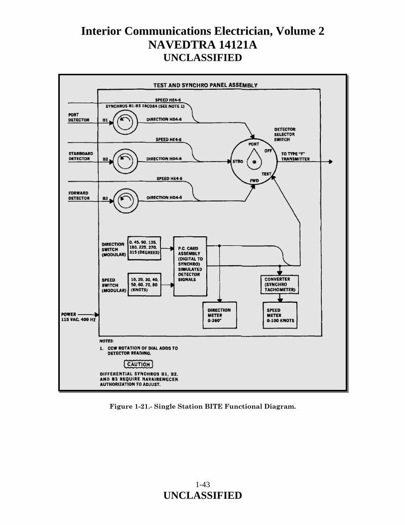
External wiring enters through a hole in either end of case assembly (4). These holes are threaded to accept stuffing tube fittings with one-inch national pipe threads. The incoming wires attach to terminal boards (5) within case assembly (4). Direction Dial Direction dial (6) and wind speed dial (7) are mounted to diffuser (8) opposite the synchros. The direction dial (6) is graduated in 5-degree intervals from 0 to 360 degrees. The wind speed dial (7) is graduated in one-knot intervals from 0 to 100 knots, covering 360 degrees. Pointers (9) attached to each synchro shaft will indicate wind speed and direction as read on the direction and speed dials during indicator operation. The indicators allow both the speed and direction dials to be manually repositioned, permitting the indicator to be mounted either horizontally or vertically without disadvantage to the observer. Knob (10) controls the intensity of lamps (11) which illuminate the dials and pointers. Red filters (14) permit illumination for night operations. BITE The BITE is used to increase the reliability of existing fleet WMIS. The BITE generates known test (synchro) signals to check the operation of the WMIS equipment. Differential synchros are used to compensate for inherent wind direction errors due to the ship's structure. Two BITE systems, Single Station BITE and Dual Station BITE, are discussed in this section. Single Station BITE The single station BITE consists of a test and synchro panel assembly (Figure 1-16). The enclosure contains a printed circuit board (1), card extractor (2), 5V and ± 15V power supplies (3 and 4), converter (5), planctary drives (6), and differential synchros (7). An interlock switch (8) automatically de-energizes the test circuit whenever the enclosure assembly door is opened. The enclosure assembly door contains direction meter (9), speed meter (10), fuses (11), 5V and ± 15V indicators (12 and 13), two rows of modular switches to test direction in degrees (14) and wind speed in knots (15), and detector selector switch (16). The five-position selector switch (16) can be positioned to OFF, TEST, PORT, STBD, and FWD. External wiring enters the enclosure assembly through stuffing tubes mounted in top and bottom cover plates (17) and attaches to terminal boards (18) within the assembly.
1-32 UNCLASSIFIED

Interior Communications Electrician, Volume 2 NAVEDTRA 14121A
UNCLASSIFIED
Figure 1-16.- Single Station BITE Test and Synchro Panel Assembly.
1-33 UNCLASSIFIED

Interior Communications Electrician, Volume 2 NAVEDTRA 14121A
UNCLASSIFIED
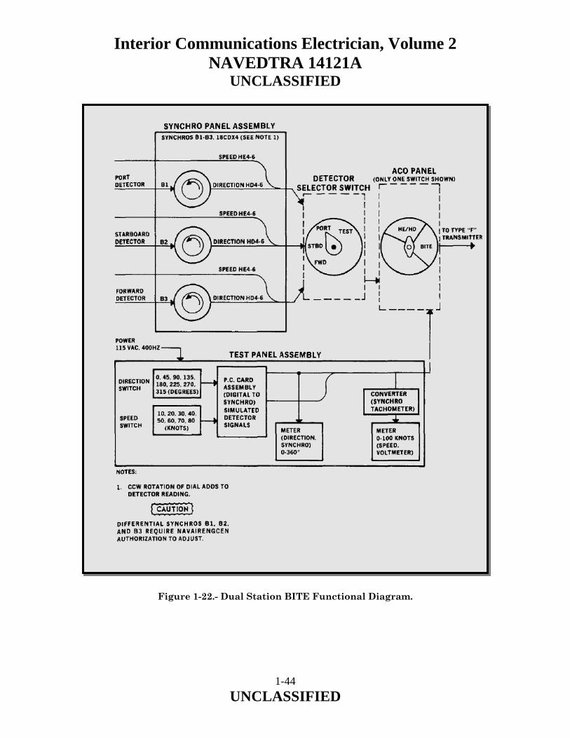
Dual Station BITE The Dual Station BITE consists of a test panel assembly (Figure 1-17) and a synchro panel assembly (Sheet 2). The enclosure of the test panel assembly contains a printed circuit board (1), card extractor (2), 5V and ± 15V power supplies (3 and 4), and converter (5). An interlock switch (6) automatically de-energizes the test circuit whenever the enclosure assembly door is opened. The enclosure assembly door contains direction meter (7), speed meter (8), fuses (9), 5V and ± 15V indicators (10 and 11), and two rows of modular switches (12 and 13) to test wind direction in degrees and wind speed in knots. A detector selector switch external to the dual station BITE permits WMIS equipment to be tested through the BITE. The synchro panel assembly (Sheet 2) houses the differential synchros (16) and planetary drives (17). External wiring enters both enclosure assemblies through stuffing tubes mounted in top and bottom cover plates (15, Sheet I and 18, Sheet 2) and attaches to terminal boards (14, Sheet 1 and 19, Sheet 2) within the assemblies.
1-34 UNCLASSIFIED

Interior Communications Electrician, Volume 2 NAVEDTRA 14121A
UNCLASSIFIED
Figure 1-17.- Dual Station BITE Test Panel Assembly and Synchro Panel
Assembly. (Sheet 1 of 2).
1-35 UNCLASSIFIED

Interior Communications Electrician, Volume 2 NAVEDTRA 14121A
UNCLASSIFIED
Figure 1-17.- Dual Station BITE Test Panel Assembly and Synchro Panel Assembly. (Sheet 2 of 2).
1-36 UNCLASSIFIED
Interior Communications Electrician, Volume 2 NAVEDTRA 14121A
UNCLASSIFIED
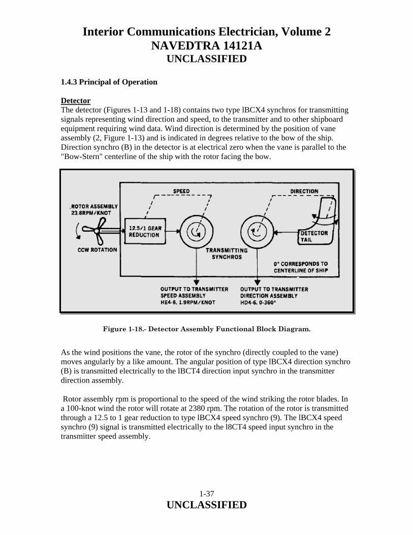
1.4.3 Principal of Operation Detector The detector (Figures 1-13 and 1-18) contains two type lBCX4 synchros for transmitting signals representing wind direction and speed, to the transmitter and to other shipboard equipment requiring wind data. Wind direction is determined by the position of vane assembly (2, Figure 1-13) and is indicated in degrees relative to the bow of the ship. Direction synchro (B) in the detector is at electrical zero when the vane is parallel to the "Bow-Stern" centerline of the ship with the rotor facing the bow. Figure 1-18.- Detector Assembly Functional Block Diagram. As the wind positions the vane, the rotor of the synchro (directly coupled to the vane) moves angularly by a like amount. The angular position of type lBCX4 direction synchro (B) is transmitted electrically to the lBCT4 direction input synchro in the transmitter direction assembly. Rotor assembly rpm is proportional to the speed of the wind striking the rotor blades. In a 100-knot wind the rotor will rotate at 2380 rpm. The rotation of the rotor is transmitted through a 12.5 to 1 gear reduction to type lBCX4 speed synchro (9). The lBCX4 speed synchro (9) signal is transmitted electrically to the l8CT4 speed input synchro in the transmitter speed assembly.
1-37 UNCLASSIFIED
Interior Communications Electrician, Volume 2 NAVEDTRA 14121A
UNCLASSIFIED
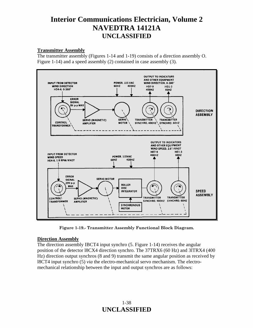
Transmitter Assembly The transmitter assembly (Figures 1-14 and 1-19) consists of a direction assembly O. Figure 1-14) and a speed assembly (2) contained in case assembly (3). Figure 1-19.- Transmitter Assembly Functional Block Diagram. Direction Assembly The direction assembly IBCT4 input synchro (5. Figure 1-14) receives the angular position of the detector l8CX4 direction synchro. The 37TRX6 (60 Hz) and 3lTRX4 (400 Hz) direction output synchros (8 and 9) transmit the same angular position as received by l8CT4 input synchro (5) via the electro-mechanical servo mechanism. The electro-mechanical relationship between the input and output synchros are as follows:
1-38 UNCLASSIFIED

Interior Communications Electrician, Volume 2 NAVEDTRA 14121A
UNCLASSIFIED
a. When the vane of the detector changes position. A signal is transmitted to the stator of type 18CT4 input synchro (5). The output signal of the type 18CT4 input synchro (5) rotor is nearly in-phase or 180 degrees out-of-phase with the line voltage depending upon which direction the vane has turned. Two voltage regulating diodes (7) limit the synchro rotor output to magnetic amplifier (6) to approximately 6.8 volts. The amplified output from the magnetic amplifier drives servo motor (7) which rotates until the output of the type l8CT4 input synchro (5) is zero. b. Rotation of the servo motor is transferred to the rotors of the 37TRX6 and 31TRX4 direction output synchros (8 and 9) through gears (18-21). Servo motor rotation is at a constant rate (7° ±1/2°/sec). If the deviation rate of the detector vane exceeds the servo motor rate the vane deviation rate is damped by the limiting factor of the servo motor. The direction signals produced by output synchros (8 and 9) are available for connection to external indicators or other equipment. Speed Assembly The stator windings of 18CT4 input synchro (11. Figure 1-14) in the transmitter are connected to the output of the speed synchro in the detector. The 37TRX6 (60 Hz) and 31TRX4 (400 Hz) output synchros (15 and 16) transmit an angular position directly proportional to the rpm of detector rotor assembly (4. Figure 1-13). The electromechanical relationship between the input and output synchros is as follows: a. When the detector rotor assembly rotates. a signal is transmitted to the stator of the 18CT4 input synchro (11. Figure 1-14). The rotor windings of input synchro (II) are connected to the input of magnetic amplifier (12). Two voltage regulating diodes (22) limit the input to the magnetic amplifier to approximately 27 volts. The output of the magnetic amplifier drives servo motor (13) which rotates, through gearing, input synchro (11), When the servo motor rotates the input synchro at the same rpm as the speed synchro in the detector is being rotated by the wind, the input to magnetic amplifier (12) is minimum (just sufficient to drive the servo motor), As the servo motor (13) rotates, it turns eighteen-tooth spiral gear (23) through a 6:1 gear reduction. NOTE The speed of spiral gear (23) is 21.155 rpm when wind velocity is 100 knots.
1-39 UNCLASSIFIED

Interior Communications Electrician, Volume 2 NAVEDTRA 14121A
UNCLASSIFIED
b. The spiral gear (23) engages the roller gear (24) of roller gear assembly (25). Action of spiral gear (23) against the roller gear (24) of roller gear assembly (25) is that of a pinion on a rack, driving roller (26) away from the center of driving discs (27). As driving roller (26) is displaced from the center of driving discs (27) it begins to rotate and reduces the speed at which spiral gear (23) is driving roller gear assembly (25). NOTE The driving discs sit on spur gears (30) which are rotated at a constant speed of 13.55 rpm by synchronous motor (14). c. When driving roller (26), has been displaced from the center of driving discs (27) a sufficient amount, the rotation of roller gear assembly (25) will be just adequate to cancel the rotation of spiral gear (23). Roller gear assembly (25) will then remain stationary with the driving roller (26) displaced some distance from the center of driving discs (27). Linear displacement of roller gear assembly (25) is converted to angular displacement by roller assembly (28). As gear (29), which is part of roller assembly (28), is rotated, output synchro transmitters (15 and 16) are positioned proportional to wind speed. NOTE One complete revolution of either of the output synchro transmitters is equal to a wind speed of 100 knots. d. Two limit switches (32) are used in the transmitter speed assembly to prevent damage and unnecessary wear of driving roller (26) and driving discs (27). As driving roller (26) approaches the center of driving discs (27), the roller shaft (24) end, located by the spiral gear (23), is forced against bell crank (31) which in turn opens limit switch (32) and breaks the circuit to synchronous motor (14). When the roller gear assembly is displaced by a wind velocity greater than 95 ±2 knots, the roller gear (24) end, located by roller assembly (28), is forced against the bell crank (31), which in turn opens limit switch (32) and breaks the circuit to servo motor (13). As wind velocity decreases a few knots, the switch will close and energize the circuit to servo motor (13). NOTE The system will oscillate between 95 ±2 knots.
1-40 UNCLASSIFIED

Interior Communications Electrician, Volume 2 NAVEDTRA 14121A
UNCLASSIFIED
Indicator The indicator direction and speed synchros (1 and 2, Figure 1-15) are electrically connected to and track the transmitter output synchros (see Figure 1-20). Pointers (9, Figure 1-15), fastened to the rotor shafts of the synchros, indicate wind direction or wind speed on separate circular dials (6 and 7). Dials and pointers are illuminated by a circuit consisting of stepdown transformer (12), variable resistor (13), and three incandescent lamps (11). The transformer reduces 115-volt input to 6.3 volts. The variable resistor controls lamp intensity by rotating knob (10). Figure 1-20.- Indicator Assembly Functional Block Diagram.
1-41 UNCLASSIFIED

Interior Communications Electrician, Volume 2 NAVEDTRA 14121A
UNCLASSIFIED
Built-In Test Equipment (BITE) The Single Station BITE and the Dual Station BITE (Figures 1-16, 1-17, 1-21, and 1-22) channel wind speed and direction information from the detectors to the system transmitters in a manner virtually identical to present day operations with the addition of directional compensation. Wind direction information is channeled through differential synchros which are adjusted during an at-sea calibration to correct for misalignment or wind variations caused by the ship's structure. The differential synchro vernier dials (Figure 1-16 and Figure 1-17, Sheet 2) on the shafts of the planetary drives (6, Figure 1-16 and 17, 7 Figure 1-17) are then locked in position. CAUTION Any attempt to adjust the differential synchros will require calibration by NAVAIRENGCEN.
1-42 UNCLASSIFIED
Interior Communications Electrician, Volume 2 NAVEDTRA 14121A
UNCLASSIFIED
Figure 1-21.- Single Station BITE Functional Diagram.
1-43 UNCLASSIFIED
Interior Communications Electrician, Volume 2 NAVEDTRA 14121A
UNCLASSIFIED
Figure 1-22.- Dual Station BITE Functional Diagram.
1-44 UNCLASSIFIED

Interior Communications Electrician, Volume 2 NAVEDTRA 14121A
UNCLASSIFIED
1.4.4 Troubleshooting Anemometer Systems Troubleshooting wind direction and indicating systems is simple once you have identified that you have a problem. Many potential problems can be avoided by careful preventive maintenance. If the trouble is not avoided, you can at least identify it by following the Planned Maintenance System (PMS) procedures. The principles of operation of the various components of the systems were included in this chapter to aid you in troubleshooting. When troubleshooting the systems, you should refer to the troubleshooting section of the technical manual. These troubleshooting tables can be very useful in that they enable personnel to locate malfunctions and take the necessary corrective action. They are also a quick reference guide. 1.4.5 Maintenance of Anemometer Systems Preventive maintenance for the system consists of periodic inspections, cleaning, and lubrication. You should refer to the appropriate technical manual for specific procedures to follow. Many potential troubles in the system can be avoided by careful preventive maintenance. Detector Most ships have a detector mounted port and starboard on the mast. By switching from one to the other while watching the indicator and comparing the readings, you can determine if there is a problem with a detector. Every 90 days and after exposure to high winds, inspect the detector mounting and tighten the mounting bolts if necessary. The rotor and vane also should be inspected every 90 days. Turn the rotor by hand to confirm that it turns freely. Rotate the vane through 360° in both directions to assure it rotates freely. If friction or binding of the vane is suspected, perform the friction test. Every 6 months, the detector should be inspected, lubricated, and, if conditions warrant, cleaned. Refer to the technical manual for specific procedures. Transmitter Every 6 months, the transmitter should be inspected, lubricated, and, if warranted, cleaned. When inspecting the transmitter, you should inspect the following:
• All moving parts for freeness. • Gears for excessive wear and broken teeth. • Bearings, gears, and other moving parts for gummed oil, dust, and so on. • Sensitive switches; turn them over and replace if worn. • Driving discs for wear.
1-45 UNCLASSIFIED

Interior Communications Electrician, Volume 2 NAVEDTRA 14121A
UNCLASSIFIED
Indicator Watch the indicator periodically for uneven movement of the pointer as this indicates a possible problem. By comparing the pointer movement of one indicator with another, you can determine if the trouble is in a single indicator or in the system. Erratic indications, resulting from excessive friction, often can be avoided by cleaning and oiling of the units. Other causes of excessive friction may be discovered during periodic maintenance inspection. When beginning a periodic inspection, observe the indicators when there is enough wind to act on the vane and rotor. Only the indicator unit requires no lubrication. 1.5.0 CROSSWIND AND HEADWIND COMPUTER ASSEMBLY AND SPEED INDICATOR Crosswind and Headwind Computer Assembly hereinafter referred to as the computer. The computer receives wind direction and wind speed signals from a WMIS transmitter, converts the values, then transmits these signals to the speed indicator. Crosswind and Headwind Speed Indicator hereinafter referred to as the speed indicator. The speed indicator receives voltages from the computer assembly. The red illuminated dials of the speed indicator display crosswind and headwind speed (in knots) of either the angle deck or straight deck, as selected by the operator. 1.5.1 Physical Description Computer The computer (Figure 1-23) consists of a chassis assembly which processes and amplifies crosswind and headwind signals. The plug-in assembly is secured in a common drip-proof case assembly by screws. It is connected electrically through mating connectors on the chassis assembly and the case assembly. External wiring enters the case assembly through two holes in the bottom, threaded to accept stuffing tube fittings with one-inch national pipe threads. The incoming wires connect to terminal boards mounted in case assembly. The chassis assembly contains two synchros two board assemblies and two reversible motors. One each of these items is associated with the wind direction input from the WMIS transmitter; the remainder is associated with the wind speed input. The chassis assembly also contains a sine-cosine potentiometer linear potentiometer dc power supply and transformer. The inductor and transformer are secured to the same mounting bracket.
1-46 UNCLASSIFIED

Interior Communications Electrician, Volume 2 NAVEDTRA 14121A
UNCLASSIFIED
Figure 1-23.- Cross and headwind computer assembly.
1-47 UNCLASSIFIED
Interior Communications Electrician, Volume 2 NAVEDTRA 14121A
UNCLASSIFIED
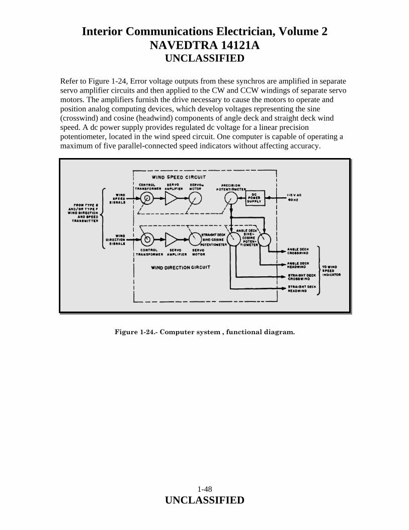
Refer to Figure 1-24, Error voltage outputs from these synchros are amplified in separate servo amplifier circuits and then applied to the CW and CCW windings of separate servo motors. The amplifiers furnish the drive necessary to cause the motors to operate and position analog computing devices, which develop voltages representing the sine (crosswind) and cosine (headwind) components of angle deck and straight deck wind speed. A dc power supply provides regulated dc voltage for a linear precision potentiometer, located in the wind speed circuit. One computer is capable of operating a maximum of five parallel-connected speed indicators without affecting accuracy. Figure 1-24.- Computer system , functional diagram.
1-48 UNCLASSIFIED

Interior Communications Electrician, Volume 2 NAVEDTRA 14121A
UNCLASSIFIED
Speed Indicator The speed indicator (Figure 1-24) receives voltages from the computer that represent the crosswind and headwind components of either angle deck or straight deck wind speed. The speed indicator consists of plug-in chassis assembly secured in watertight case assembly. The case and chassis assemblies are connected electrically through a plug connector on the chassis assembly and a mating connector in case assembly. External wiring enters through a hole in the end of case assembly. This hole is threaded to accept stuffing tube fittings with one-inch national pipe threads. The incoming wires connect to terminal board within the case assembly. The chassis assembly contains crosswind microammeter and headwind microammeter. Wind speeds are observed on illuminated dials which are calibrated in knots. Two circular diffusers cause illumination, provided by four lamp assemblies, to be diffused uniformly around the periphery of the indicators. Knob controls the intensity of the lamps. Red filters permit illumination for night operations. Two additional lamp assemblies with red filters are used to indicate angle deck (A) or straight deck (S) values. The speed indicator receives voltages from the computer that represent the sine (crosswind) and cosine (headwind) components of either angle deck or straight deck wind speed, as selected by an existing ANGLE DECK-OFF-STRAIGHT DECK switch under manual control of the operator. The wind component voltages are applied directly to microammeter movements in the indicator. Wind speeds are observed on illuminated dials calibrated in knots. Operations that cause off-scale pointer indications will not damage the component indicators. 1.5.2 Maintenance and Troubleshooting The maintenance of this unit is outlined in the appropriate PMS documents. The technical manual for the equipment contains an adequate troubleshooting chart. Therefore, there should be no difficulty in keeping the unit running. You should be sure that personnel trying to repair the amplifier units are familiar with the proper techniques for working with transistors and that they follow the instructions in the proper technical manual. The manufacturer has specified the use of certain meters for analyzing the condition of the components of the unit, and, where possible, these should be used.
1-49 UNCLASSIFIED

Interior Communications Electrician, Volume 2 NAVEDTRA 14121A
UNCLASSIFIED
1.6.0 DIGITAL WIND SYSTEM The digital wind system is designed to provide the ship’s combat system with accurate relative and true wind direction and speed. The system provides this data to the combat system, as well as presenting them to dedicated digital wind system Multifunction Color Repeater (MFCR) displays. The main system components are illustrated in figure 1-25.
Figure 1-25.- Main System Units.
1-50 UNCLASSIFIED

Interior Communications Electrician, Volume 2 NAVEDTRA 14121A
UNCLASSIFIED
1.6.1 System Components The digital wind system is comprised of the following components: Anemometers The digital wind system uses two anemometers fitted to the mainmast. The anemometers are the prime sensor units within the system and are fitted to the mainmast, well away from any structures that may affect the unobstructed flow of wind across the sensor. The anemometer sensors are in a cruciform structure with an ultrasonic transducer fitted to the head of each arm of the cross. The time taken for the emitted ultrasonic beams to reach the opposite transducers is affected by the wind blowing across the cruciform structure. The resultant wind speed and direction data is formatted and transmitted via the junction box to Meteorological Interface Units (MIUs) for processing. Internal anti-icing heaters ensure operation in all but the most severe icing environments. The anemometers are fitted with Radar Absorbent Material (RAM) after their installation on the mast. Junction Box The junction box contains an array of diodes and tag boards that allow power supplies to be fed to both anemometers from either MIU. Data from both anemometers is connected within the junction box and fed to both MIUs for processing. Meteorological Interface Unit Two identical MIUs are fitted to ensure 100% redundancy and system availability. The MIU houses the main processing and interfacing elements of the digital wind system. Inputs to the MIU consist of: a. wind speed and direction data from the anemometers, and b. ship’s heading and speed data from the Fiber Optic Data Multiplex System (FODMS). Following processing, the MIU processor reformats the relative wind data into raw and damped data formats for transmission to the ship’s FODMS and distribution around the ship. Multifunction Color Repeater (MFCR) The wind data is distributed by the FODMS to the combat system and three MFCRs. Ship’s heading and speed are also input to the MFCRs to convert the relative wind data into true speed and direction. This data is then available to the users via the MFCR Thin Film Transistor (TFT) display. The user is able to select various presentations of the data via a series of softkeys on the display’s front panel.
1-51 UNCLASSIFIED

Interior Communications Electrician, Volume 2 NAVEDTRA 14121A
UNCLASSIFIED
1.6.2 Component Location Anemometer Location The anemometers are situated on the extremities of the lower yardarm of the mainmast. One anemometer is located to port and the other to starboard. Junction Box Location The junction box is situated in the director equipment room 1, above the pilot house. MIU Location The two MIUs are situated in Director Equipment Room 1, on opposite bulkheads, and are connected to separate sources of ship’s power to improve survivability. Each MIU is physically identified as either MIU A or MIU B. MFCR Location One MFCR is situated on the bridge, a second is located in Helicopter Station and the third is located in the Recovery Assist Secure and Traverse (RAST) Station. 1.6.3 Functional Overview The digital wind system performs five major functions as follows: a. detection, b. interface processing, c. display, d. power distribution, and e. Built In Test (BIT). Figure 1-26 illustrates the functional arrangement of the system.
1-52 UNCLASSIFIED
Interior Communications Electrician, Volume 2 NAVEDTRA 14121A
UNCLASSIFIED
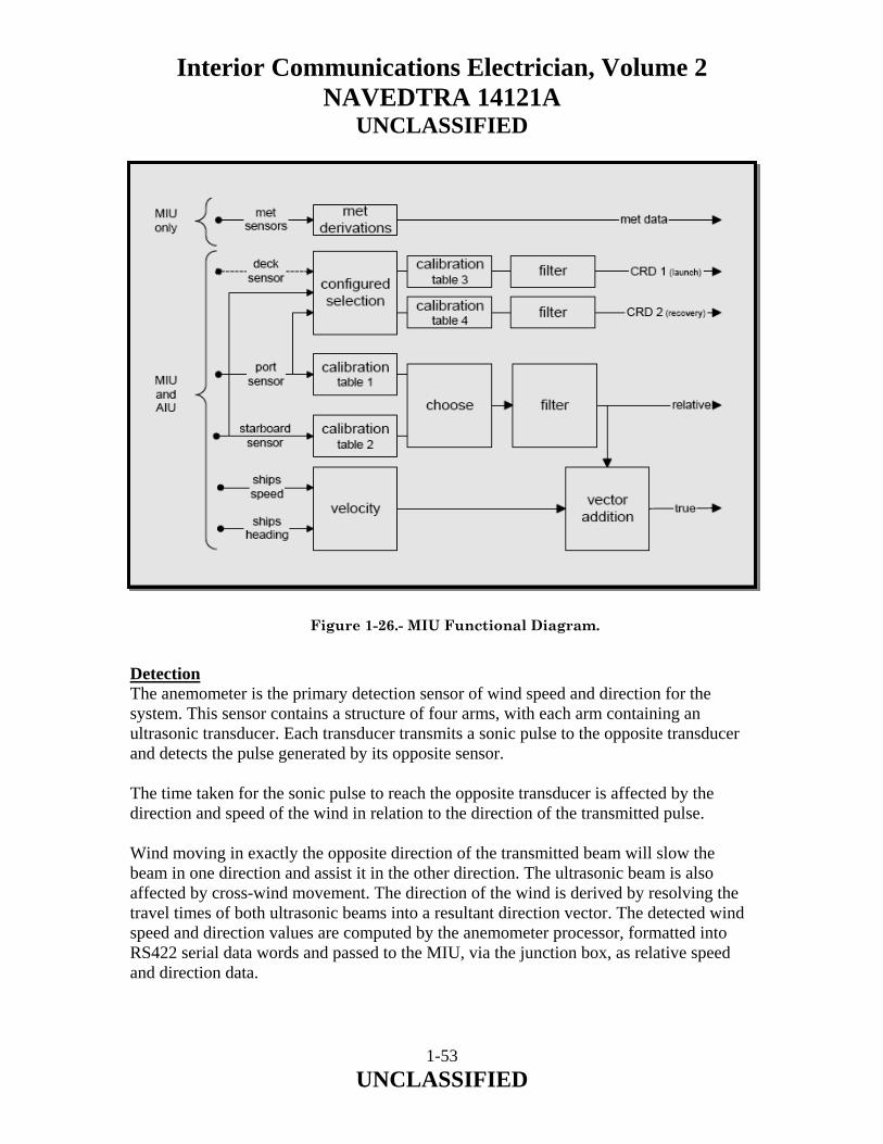
Figure 1-26.- MIU Functional Diagram. Detection The anemometer is the primary detection sensor of wind speed and direction for the system. This sensor contains a structure of four arms, with each arm containing an ultrasonic transducer. Each transducer transmits a sonic pulse to the opposite transducer and detects the pulse generated by its opposite sensor. The time taken for the sonic pulse to reach the opposite transducer is affected by the direction and speed of the wind in relation to the direction of the transmitted pulse. Wind moving in exactly the opposite direction of the transmitted beam will slow the beam in one direction and assist it in the other direction. The ultrasonic beam is also affected by cross-wind movement. The direction of the wind is derived by resolving the travel times of both ultrasonic beams into a resultant direction vector. The detected wind speed and direction values are computed by the anemometer processor, formatted into RS422 serial data words and passed to the MIU, via the junction box, as relative speed and direction data.
1-53 UNCLASSIFIED

Interior Communications Electrician, Volume 2 NAVEDTRA 14121A
UNCLASSIFIED
Interface Processing In the dual MIU redundancy configuration installed in the DDG 51 Flight IIa class, one of the MIUs is assigned as the primary unit and the other is assigned as the secondary unit. MIU A is the primary unit. Under normal operating conditions, the primary unit performs all interface processing while the secondary unit only provides status messages to indicate its status (‘am alive’ MIU status bit). The MIU status bit is set to ‘0’ to indicate normal condition and is set to ‘1’ when a fault condition is detected. In the event that the primary MIU detects a fault condition, the secondary MIU detects the setting of the primary’s ‘am-alive’ message MIU status bit to 1, or the lack of any status message from the primary MIU, and assumes control of the system, performing all interface processing functions. Data lines from each anemometer are connected for input to both MIUs within the junction box. There are two types of data provided by the MIU: a. raw data from both anemometers, and b. single sensor output damped data (referred to as damped data). Raw data from the anemometers is transmitted to the ship’s FODMS for distribution to the ship. For the single sensor output data, the primary MIU processor determines which of the anemometers is the windward instrument and selects this device as the more accurate (since the leeward anemometer may be reading incorrectly due to wind shadows caused by the ship’s structure). The processing function contains a 5° hysteresis band about the changeover point between sensors. This prevents jitter in the output data when the wind direction is oscillating around the changeover point between port and starboard sensors. A damping filter is also applied to the raw data to minimize erratic swings in direction and speed caused by gusting winds. This produces damped, relative wind data. Ship’s heading and speed, and the other MIU status message are fed to the MIU processor via an Ethernet 10Base2 interface with the FODMS. These inputs are used by the processing function to convert the damped, relative wind speed and direction to true values. However, this data is not fed back to the FODMS, as the relative to true conversion process also occurs in the MFCRs.
1-54 UNCLASSIFIED

Interior Communications Electrician, Volume 2 NAVEDTRA 14121A
UNCLASSIFIED
The outputs from the MIU are raw port and starboard wind data, damped port or starboard wind data, and ‘am-alive’ status messages. Damped and raw wind data is reformatted into suitable form for transmission and passed to the FODMS via the 10Base2 Ethernet interface, where it is distributed to the combat system. The MFCRs only receive the damped data from the FODMS. Display The primary display element of the digital wind system is embedded in the MFCR (ref figure 1-27). This unit receives the damped wind data (from the primary MIU) and ship’s speed, heading, roll and pitch from the FODMS in RS422 format. The single board computer (SBC) within the MFCR uses the ship’s parameter data to convert the damped relative data from the MIU into true values. This data is then reformatted for display on the Thin Film Transistor (TFT) display. Either relative or true wind data can be selected for display.
Figure 1-27.- MFCR Front View.
1-55 UNCLASSIFIED

Interior Communications Electrician, Volume 2 NAVEDTRA 14121A
UNCLASSIFIED
Ship's Helicopter Operating Limit Diagrams (SHOLD) Envelopes The SHOLD displays ship’s helicopter landing envelopes, which allow for ‘Fox Corpen’ data to give a new ship’s heading and speed to provide safe helicopter operating conditions in instances where the present conditions are unsafe. Power Distribution The digital wind system derives its primary power from the ship’s 115 V, 60 Hz, single-phase supply. All MIU internal supplies are derived from this source. Separate 115 V AC ship’s supplies are fed to each MIU to retain the dual redundant feature of the system. The 115 V AC is fed to the MIU where it is used to power the main system power supply unit. This unit produces the supplies for the MIU internal components (main processor and Ethernet modules) as well as the power supplies for the anemometer electronics and heaters, via the junction box. The junction box consists of an array of diodes that permits the connection of +24 V DC power supplies to both anemometers from both MIUs, providing the sensors with continuous power in the event of a loss of +24 V DC from one of the MIUs. The diodes act as safety devices, preventing the power supplies from one MIU appearing at the output of the other whenever it is shutdown or in a fault condition. Each MFCR derives its power separately from the ship’s 115 V, 60 Hz supply. Built-In Test (BIT) The digital wind system incorporates several BIT features to identify fault conditions and display system status data at the MFCRs. The anemometer contains circuitry and firmware that perform periodic testing of the analog and digital modules within the anemometer. Failure of anemometer components causes a fault message to be transmitted to the MIUs. The MIU processor performs periodic testing of its own board components. The processor produces an ‘am-alive’ message containing status bits for each anemometer and the MIU itself. Identification of a failure within the MIU causes the MIU status bit in the ‘am-alive’ message to be set to ‘1’ (fault condition). Similarly, if one of the anemometers passes a fault message to the MIU processor, the relevant anemometer status bit in the ‘am-alive’ message is set to ‘1’. The ‘am-alive’ message is passed to the FODMS, and consequently, the other MIU and all MFCRs, where a fault indication is displayed.
1-56 UNCLASSIFIED

Interior Communications Electrician, Volume 2 NAVEDTRA 14121A
UNCLASSIFIED
The MFCR built in test facility automatically tests the display, memory and input data each time the MFCR is switched on. Whenever the MFCR is switched on, the display, processor, keypad and memory are all tested and user verified. Status monitoring is continuous. A failure in the MFCR input channel from the FODMS will illuminate the input data channel indicator (CH1 FAIL) on the TFT display. A failure in a specific packet of data (timeout for new data to be received) will result in a red line through that particular digital data field on the MFCR screen. Loss of the pitch input, for example, will result in a red bar being displayed across the section of the MFCR page on which pitch data is presented. There is additionally a status page which displays the ‘am alive’ data from each processor. A bright green spot indicates the unit is active and selected. A dark green spot indicates that the associated unit is serviceable but not selected, and a red spot indicates that the unit is unavailable. A failure of any status bit results is a ‘SERVICE’ message being displayed in the bottom left hand corner of every page on the MFCR.
1-57 UNCLASSIFIED
Interior Communications Electrician, Volume 2 NAVEDTRA 14121A
UNCLASSIFIED
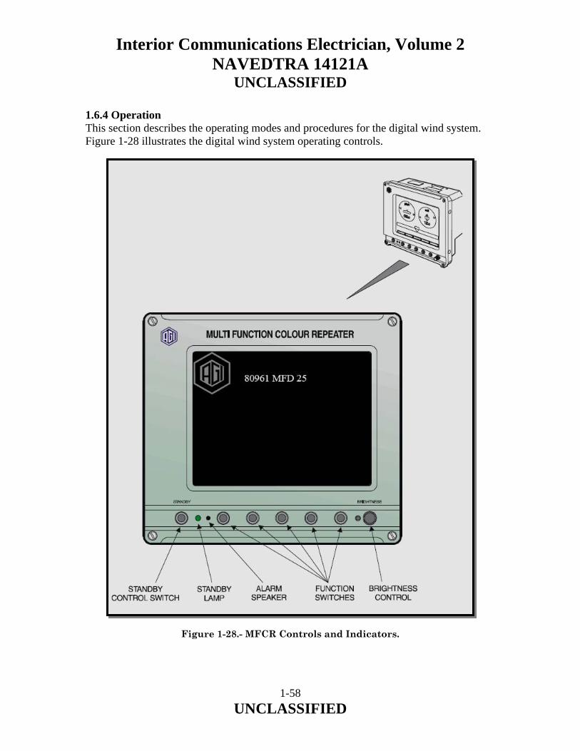
1.6.4 Operation This section describes the operating modes and procedures for the digital wind system. Figure 1-28 illustrates the digital wind system operating controls.
Figure 1-28.- MFCR Controls and Indicators.
1-58 UNCLASSIFIED

Interior Communications Electrician, Volume 2 NAVEDTRA 14121A
UNCLASSIFIED
Modes of Operation The digital wind system has two modes of operation: a. normal (auto) operation, and b. sensor select operation. Both modes of operation of the system are achieved by switching the Meteorological Interface Units (MIUs) and the Multifunction Color Repeaters (MFCRs) on locally. In normal mode the active MIU is set to AUTO. In Sensor Select mode the button on the active MIU is repeatedly pressed until the required sensor is shown to be selected by the corresponding LED. The user can select required pages at the MFCRs to access various information pertaining to wind speed and direction data as it relates to helicopter operations. Correct Ships Helicopter Operating Limit Diagrams (SHOLD) envelopes can also be selected at the MFCR. 1.6.5 Controls and Indicators The digital wind system incorporates controls and indicators that can be used to access information and monitor the status of the system. Refer to table 1-2 for a list of the controls and table 1-3 for a list of the indicators embedded in the digital wind system. MFCR Controls and Indicators The following controls are available to the operator at the MFCR (refer to figure 1-28 and table 1-2).
1-59 UNCLASSIFIED

Interior Communications Electrician, Volume 2 NAVEDTRA 14121A
UNCLASSIFIED
Control Unit Location Function
ON/OFF switch SW1 MIU Controls application of ship’s 115 V, 60 Hz to the MIU PSU. Note that this switch is only accessible with the front cover open.
WARNING The digital wind system is powered from 115 V AC. Contact with this supply can be lethal. All ship precautions and procedures pertaining to working on live equipment are to be observed when performing the following steps.
Sensor Select MIU Selects between ‘Auto’, ‘Port’ and ‘Stbd’ sensor.
STANDBY pushbutton MFCR keypad During normal operation, toggling the STANDBY button inhibits or enables the display without the need for rebooting.
Softkey 1 MFCR keypad Relative wind with ship’s speed and heading page. SHOL options page. Wind component display page.
Softkey 2 MFCR keypad Used on the SHOL pages. Softkey 3 MFCR keypad Used on the SHOL pages. Softkey 4 NEXT MFCR keypad Selects next display page. Softkey 5 PREV MFCR keypad Selects previous display page. Dimmer control MFCR keypad Adjusts display brightness. Table 1-2.- Digital Wind System Controls.
1-60 UNCLASSIFIED

Interior Communications Electrician, Volume 2 NAVEDTRA 14121A
UNCLASSIFIED
Indicator Unit Location Function
ON/OFF switch SW1 MIU Illuminated power switch. Glows orange when 115 V, 60 Hz supplied to MIU (SW 1 in the ON position).
PSU LED 1 (red) MIU PSU +5 V DC output O.K. Note that this switch is only accessible with the front cover open. WARNING The digital wind system is powered from 115 V AC. Contact with this supply can be lethal. All ship precautions and procedures pertaining to working on live equipment are to be observed when performing the following steps.
PSU LED 2 (red) MIU PSU +15 V DC output O.K. Note that this switch is only accessible with the front cover open. WARNING The digital wind system is powered from 115 V AC. Contact with this supply can be lethal. All ship precautions and procedures pertaining to working on live equipment are to be observed when performing the following steps.
PSU LED 3 (red) MIU PSU -15 V DC output O.K. Note that this switch is only accessible with the front cover open. WARNING The digital wind system is powered from 115 V AC. Contact with this supply can be lethal. All ship precautions and procedures pertaining to working on live equipment are to be observed when performing the following steps.
Sensor LED 1 MIU front cover Indicates that sensor selection is set to AUTOMATIC (MIU determines which sensor is selected as the wind data input source).
Sensor LED 2 MIU front cover Indicates that the PORT sensor has been manually selected and the automatic selection function has been overridden.
Sensor LED 3 MIU front cover Indicates that the STARBOARD sensor has been manually selected and the automatic selection function has been overridden.
Table 1-3.- Digital Wind System Indicators.
1-61 UNCLASSIFIED

Interior Communications Electrician, Volume 2 NAVEDTRA 14121A
UNCLASSIFIED
a. Standby Switch (Display ON/OFF). This switch allows the display to be switched off if not required. When depressed to bring the MFCR on line, the data is instantaneously available. b. Brightness Control. Using the rotary control establishes the brightness and can be adjusted from a minimum to a maximum, viewable in bright sunlight. c. Five Function Soft-key Controls. These controls are software defined, with the function performed dependent on the displayed page. The function of each control for a particular page is shown at the bottom of the display, immediately above that control. 1.6.6 Normal Operating Procedure To operate the system, perform the following procedure (refer to figure 1-28 and figure 1-29): a. Ensure that both circuit breakers supplying 115 V, 60 Hz to the MIUs are in the OFF position. b. Ensure that the three circuit breakers supplying 115 V, 60 Hz to the MFCRs are in the OFF position. c. Ensure that the ship’s Fiber Optic Data Multiplex System (FODMS) is operating and serviceable. d. Set the circuit breakers that supply the MIUs with 115 V, 60 Hz to ON. WARNING The digital wind system is powered from 115 V AC. Contact with this supply can be lethal. e. At each MIU:
1. Open the MIU front cover. 2. Set the power switch to ON. 3. Close the front cover. 4. Check the sensor override indicators at the bottom of the MIU front panel to ensure that ‘AUTO’ is illuminated. If either ‘PORT’ or ‘STARBOARD’ is selected, repeatedly depress the ‘Sensor Select’ button until the ‘AUTO’ LED is illuminated.
1-62 UNCLASSIFIED

Interior Communications Electrician, Volume 2 NAVEDTRA 14121A
UNCLASSIFIED
Figure 1-29.- MIU Controls and Indicators.
1-63 UNCLASSIFIED

Interior Communications Electrician, Volume 2 NAVEDTRA 14121A
UNCLASSIFIED
f. Set the circuit breakers that supply the MFCRs with 115 V, 60 Hz to ON. g. Press the Standby switch. NOTE Once the MFCR is operating, operation of the Standby switch causes the display to be toggled between on and off, without rebooting the MFCR processor. h. Observe that the MFCR start up display is present on the MFCR (refer to figure 1-28). After a few seconds, observe the MFCR display at each MFCR reverts to one of the display pages (the MFCR will display the last page that was used before being shut down). i. If necessary, adjust the brilliance for individual requirements. At each MFCR, ensure that there are no fault messages indicated in the lower left hand corner of the screen. A horizontal red bar through a field indicates that the particular data packet is invalid. If the messages SERVICE or CH1 FAIL are displayed in the lower left corner of the display, refer to the Technical Manual for recommended actions. NOTE The available displays are shown in the figures in this section. j. At startup, the MFCR will display the issue status of the current software (refer to figure 1-28) the numbers following MFD being the software issue. Checks against the ship’s configuration status should be made to ensure that it is correct as it may effect the layout and type of the pages. k. Confirm that all allocated pages can be accessed from the MFCR by cycling through the available pages. Ensure that each page is complete as per the relevant display. To switch off the display but not the processor, press the Standby switch and observe that the standby indicator is lit. To switch the display back on, press the Standby switch again. Observe that the Standby indicator is extinguished, and the last page used is displayed.
1-64 UNCLASSIFIED
Interior Communications Electrician, Volume 2 NAVEDTRA 14121A
UNCLASSIFIED
1.6.7 Sensor Select Operating Procedure The turn on procedure is the same as for normal operation, except that the Sensor Select button on the MIU is used to force data to be read from the desired anemometer, either port or starboard. At the primary MIU (MIU A is the default primary unit) front panel, select either ‘PORT’ or ‘STARBOARD’ by repeatedly depressing the ‘Sensor Select’ button until the desired sensor LED is illuminated. NOTE The normal operating mode is to have the AUTO LED illuminated. On completion of the requirement to operate the digital wind system with a particular sensor selected, the primary MIU should be returned to automatic by repeatedly depressing the Sensor Select button until the AUTO LED is illuminated. 1.6.8 General Information The following paragraphs describe the pages displayed at the MFCR. It should be noted that the following pages are examples only to ensure the correct pages are displayed. Check the software issue as displayed at startup (refer to figure 1-28). Prime Function The pages displayed at the MFCRs pertain to wind speed and direction parameters. This information is utilized for general information and specifically as they affect ship helicopter operating procedures. Available Pages Examples of the dedicated pages available at the MFCRs are: a. System Status, b. SHOLD 1 /2, c. SHOLD 2/2, d. True and Relative Wind and Ship’s Velocity in Digital Format, NOTE Tape refers to the style or format in which ship’s heading is displayed; here a scrolling tape or ribbon is used.
1-65 UNCLASSIFIED

Interior Communications Electrician, Volume 2 NAVEDTRA 14121A
UNCLASSIFIED
e. Roll, Pitch and Tape Heading, and f. Relative Wind, Tape Heading, Speed Bar Graph and Digital True Wind and Local Time. System Status Page A display of the system status for the DDG-51 system is shown (figure 1-30). The status flag (dot) allocated to the unit will be bright green to show that the current wind data is coming from the sensor or MIU in question. They will be dark green when status packets are still arriving, indicating that the unit is still healthy or will go red if not. Figure 1-30.- System Status Page. Ship’s Helicopter Operating Limit Diagrams (SHOLD) Page A SHOLD is a polar plot of relative wind speed and direction. Combinations of wind speed/direction (referred to as wind envelopes) considered safe to operate the helicopter are then superimposed on the polar plot. The SHOLD system will give a green (go) status if the wind is within limits, and a (no-go) if outside limits, to assist the flight officer to make an assessment on the safety of flying operations. There are four envelopes available for selection.
1-66 UNCLASSIFIED
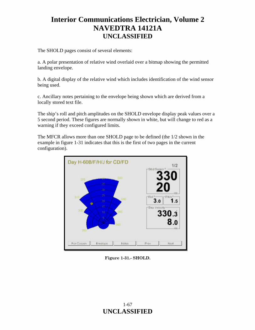
Interior Communications Electrician, Volume 2 NAVEDTRA 14121A
UNCLASSIFIED
The SHOLD pages consist of several elements: a. A polar presentation of relative wind overlaid over a bitmap showing the permitted landing envelope. b. A digital display of the relative wind which includes identification of the wind sensor being used. c. Ancillary notes pertaining to the envelope being shown which are derived from a locally stored text file. The ship’s roll and pitch amplitudes on the SHOLD envelope display peak values over a 5 second period. These figures are normally shown in white, but will change to red as a warning if they exceed configured limits. The MFCR allows more than one SHOLD page to be defined (the 1/2 shown in the example in figure 1-31 indicates that this is the first of two pages in the current configuration). Figure 1-31.- SHOLD.
1-67 UNCLASSIFIED
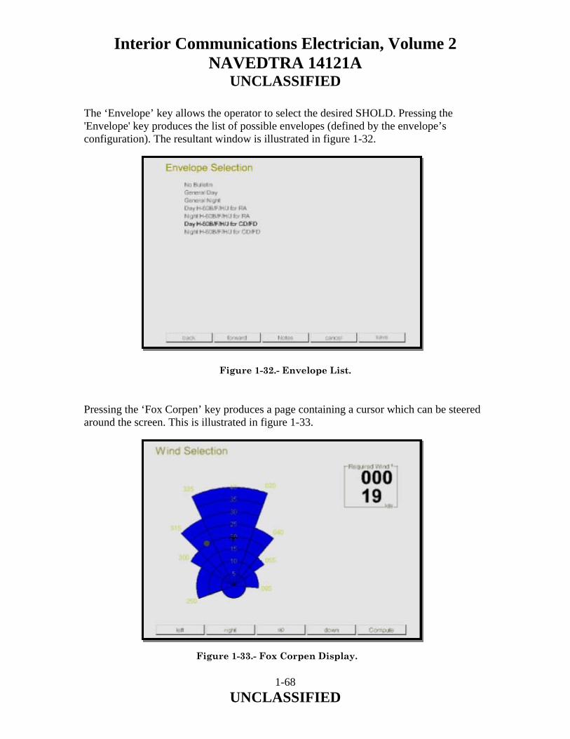
Interior Communications Electrician, Volume 2 NAVEDTRA 14121A
UNCLASSIFIED
The ‘Envelope’ key allows the operator to select the desired SHOLD. Pressing the 'Envelope' key produces the list of possible envelopes (defined by the envelope’s configuration). The resultant window is illustrated in figure 1-32.
Figure 1-32.- Envelope List. Pressing the ‘Fox Corpen’ key produces a page containing a cursor which can be steered around the screen. This is illustrated in figure 1-33.
Figure 1-33.- Fox Corpen Display.
1-68 UNCLASSIFIED

Interior Communications Electrician, Volume 2 NAVEDTRA 14121A
UNCLASSIFIED
When the ‘Compute’ key is pressed, the MFCR recommends two possible ship speed and course combinations which would produce the desired relative wind, given the current true wind as shown in figure 1-34.
Figure 1-34.- Fox Corpen Solution Display. Pressing the Notes page produces notes associated with the particular envelope (refer to figure 1-35).
Figure 1-35.- SHOLD Notes Display.
1-69 UNCLASSIFIED
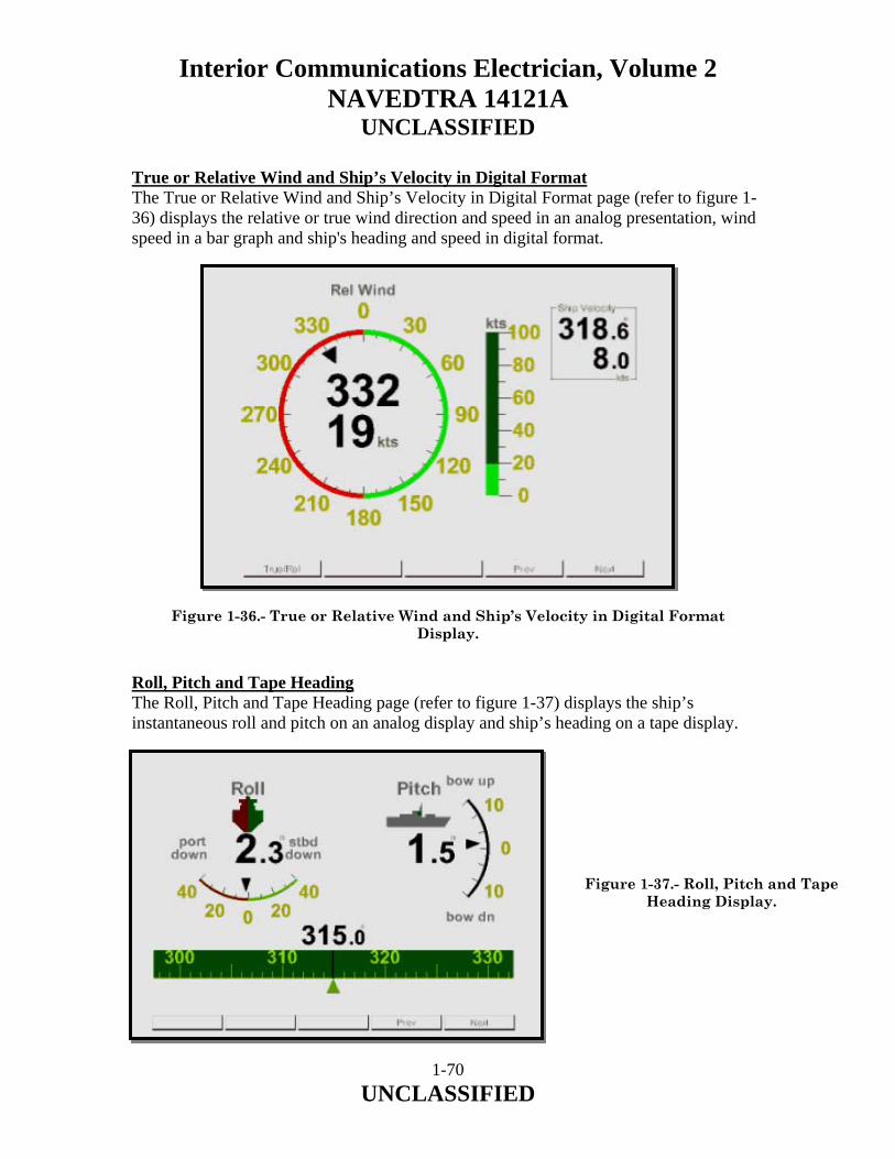
Interior Communications Electrician, Volume 2 NAVEDTRA 14121A
UNCLASSIFIED
True or Relative Wind and Ship’s Velocity in Digital Format The True or Relative Wind and Ship’s Velocity in Digital Format page (refer to figure 1-36) displays the relative or true wind direction and speed in an analog presentation, wind speed in a bar graph and ship's heading and speed in digital format.
Figure 1-36.- True or Relative Wind and Ship’s Velocity in Digital Format Display.
Roll, Pitch and Tape Heading The Roll, Pitch and Tape Heading page (refer to figure 1-37) displays the ship’s instantaneous roll and pitch on an analog display and ship’s heading on a tape display.
Figure 1-37.- Roll, Pitch and Tape Heading Display.
1-70 UNCLASSIFIED
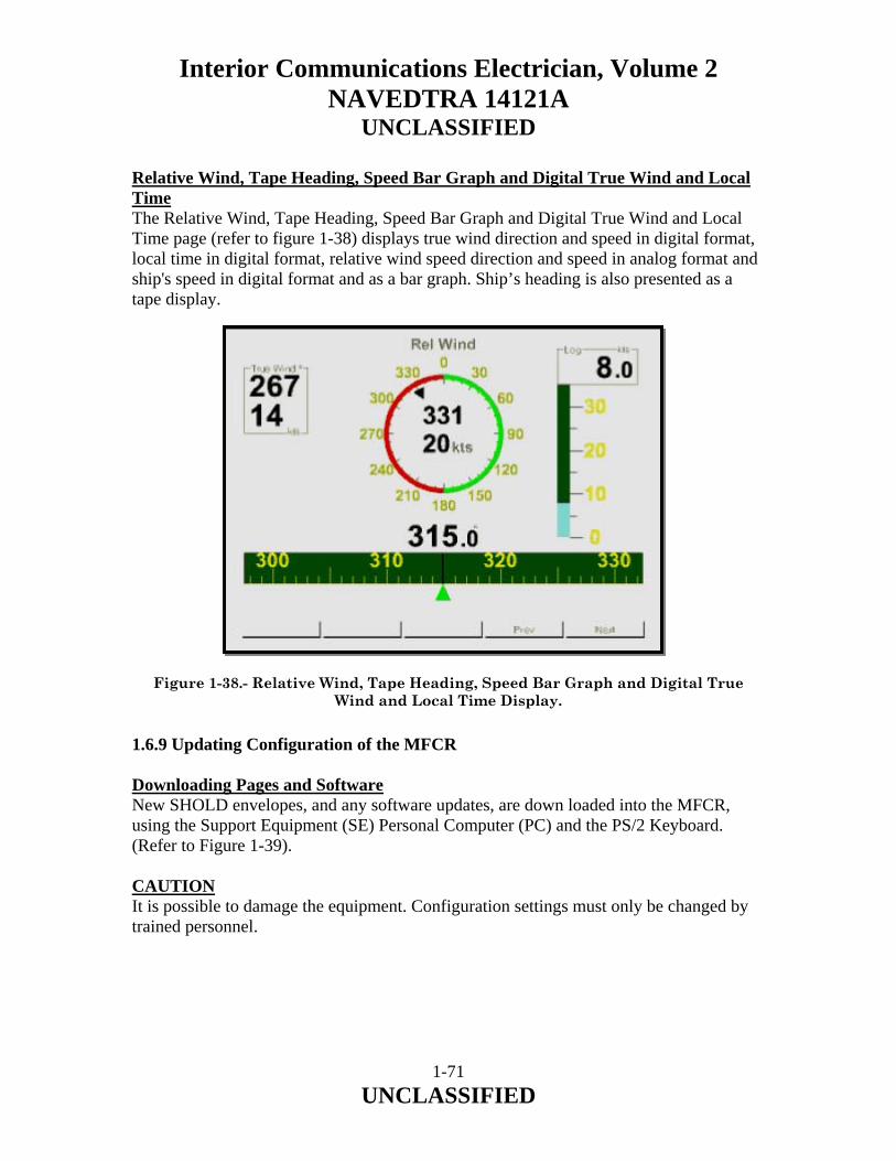
Interior Communications Electrician, Volume 2 NAVEDTRA 14121A
UNCLASSIFIED
Relative Wind, Tape Heading, Speed Bar Graph and Digital True Wind and Local Time The Relative Wind, Tape Heading, Speed Bar Graph and Digital True Wind and Local Time page (refer to figure 1-38) displays true wind direction and speed in digital format, local time in digital format, relative wind speed direction and speed in analog format and ship's speed in digital format and as a bar graph. Ship’s heading is also presented as a tape display.
Figure 1-38.- Relative Wind, Tape Heading, Speed Bar Graph and Digital True Wind and Local Time Display.
1.6.9 Updating Configuration of the MFCR Downloading Pages and Software New SHOLD envelopes, and any software updates, are down loaded into the MFCR, using the Support Equipment (SE) Personal Computer (PC) and the PS/2 Keyboard. (Refer to Figure 1-39). CAUTION It is possible to damage the equipment. Configuration settings must only be changed by trained personnel.
1-71 UNCLASSIFIED

Interior Communications Electrician, Volume 2 NAVEDTRA 14121A
UNCLASSIFIED
Figure 1-39.- MCFR, PS/2 Keyboard and PC Configuration.
1-72 UNCLASSIFIED
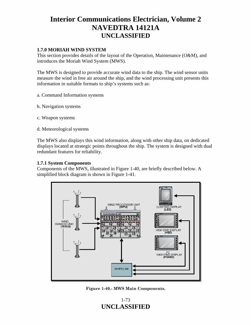
Interior Communications Electrician, Volume 2 NAVEDTRA 14121A
UNCLASSIFIED
1.7.0 MORIAH WIND SYSTEM This section provides details of the layout of the Operation, Maintenance (O&M), and introduces the Moriah Wind System (MWS). The MWS is designed to provide accurate wind data to the ship. The wind sensor units measure the wind in free air around the ship, and the wind processing unit presents this information in suitable formats to ship’s systems such as: a. Command Information systems b. Navigation systems c. Weapon systems d. Meteorological systems The MWS also displays this wind information, along with other ship data, on dedicated displays located at strategic points throughout the ship. The system is designed with dual redundant features for reliability. 1.7.1 System Components Components of the MWS, illustrated in Figure 1-40, are briefly described below. A simplified block diagram is shown in Figure 1-41.
Figure 1-40.- MWS Main Components.
1-73 UNCLASSIFIED
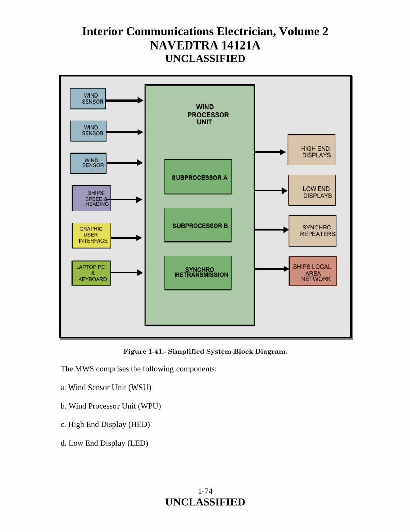
Interior Communications Electrician, Volume 2 NAVEDTRA 14121A
UNCLASSIFIED
Figure 1-41.- Simplified System Block Diagram. The MWS comprises the following components: a. Wind Sensor Unit (WSU) b. Wind Processor Unit (WPU) c. High End Display (HED) d. Low End Display (LED)
1-74 UNCLASSIFIED

Interior Communications Electrician, Volume 2 NAVEDTRA 14121A
UNCLASSIFIED
The following items may also be supplied as part of the MWS to support specific installations: e. Uninterruptible Power Supply (UPS) f. 28VDC Power Supply Unit (PSU) g. Network Switch Rack Wind Sensor Unit (WSU) The WSU shown in Figure 1-42, is the prime sensor unit of the system. The number of WSUs installed in a particular system is dependent on the ship class or shore station. There may be up to five (5) of them on any one installation. Onboard ships, they are typically installed on the yardarm away from any structure that may affect the unobstructed flow of wind. The number of WSUs installed in a particular system is dependent on the ship class or shore station. On aircraft carriers there is a third WSU installed on a forward mast.
Figure 1-42.- WSU General View.
1-75 UNCLASSIFIED
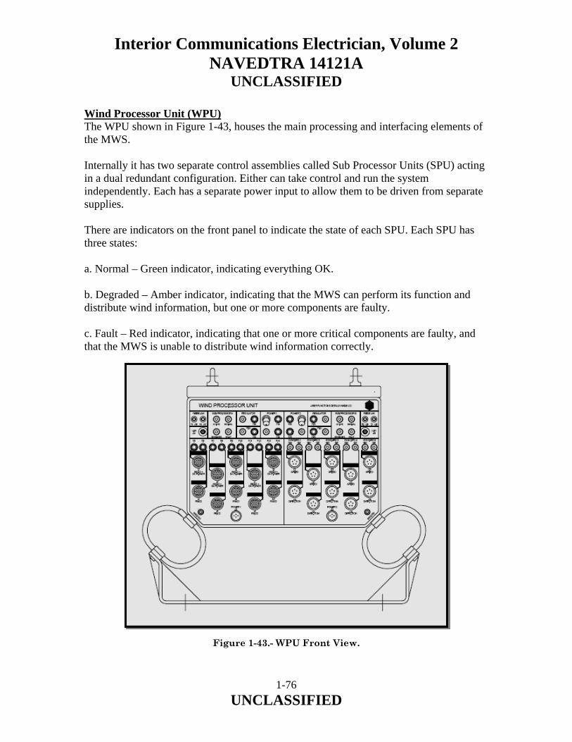
Interior Communications Electrician, Volume 2 NAVEDTRA 14121A
UNCLASSIFIED
Wind Processor Unit (WPU) The WPU shown in Figure 1-43, houses the main processing and interfacing elements of the MWS. Internally it has two separate control assemblies called Sub Processor Units (SPU) acting in a dual redundant configuration. Either can take control and run the system independently. Each has a separate power input to allow them to be driven from separate supplies. There are indicators on the front panel to indicate the state of each SPU. Each SPU has three states: a. Normal – Green indicator, indicating everything OK. b. Degraded – Amber indicator, indicating that the MWS can perform its function and distribute wind information, but one or more components are faulty. c. Fault – Red indicator, indicating that one or more critical components are faulty, and that the MWS is unable to distribute wind information correctly.
Figure 1-43.- WPU Front View.
1-76 UNCLASSIFIED

Interior Communications Electrician, Volume 2 NAVEDTRA 14121A
UNCLASSIFIED
There is an additional green indicator to indicate which SPU is currently active. The “RS422 and power” connections are used for the wind sensor unit inputs, and also for the primary connection to the Flight Critical High End Display (FCHED). The power outputs for these connections are individually fused. The “RS422 only” connections are used for the serial connections to other ships systems. The “dual synchro” outputs are dual, giving both speed and direction for any one-wind measurement. These are used to attach to legacy systems that require the wind input in this format. Legacy systems may include such as the Integrated Launch and Recovery Television System Surveillance (ILARTS) System and the AN/SPN-46 Radar. The WPU incorporates built-in test equipment and provision for an external PC and Graphical User Interface (GUI) for detailed fault reporting and system reconfiguring facilities. Modular construction used in the WPU unit enables the system to be expanded to fit many different installations, and also be reconfigured, and maintained with a minimum of down time. Inputs and outputs to the WPU consist of: a. Wind speed and direction data from each WSU, including the status data of the WSU, over RS422 cabling with power. b. Ship’s speed, heading, roll and pitch data from the ship’s navigation system over fiber optic Ethernet. c. Processed wind speed and direction data distributed to “ships” systems over Ethernet and synchro signals. d. Processed wind speed and direction, and ship’s navigational data distributed to MWS displays over both Ethernet and RS422 cabling. e. Status from each MWS display over both RS422 cabling with power and Ethernet.
1-77 UNCLASSIFIED
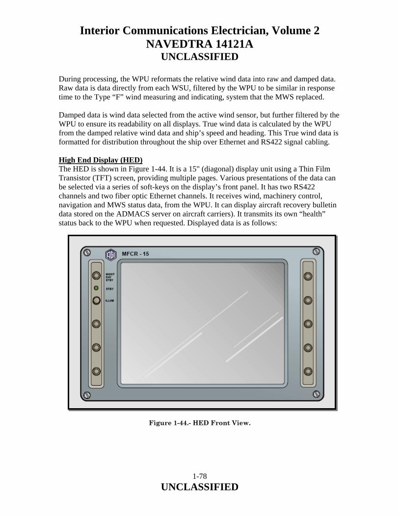
Interior Communications Electrician, Volume 2 NAVEDTRA 14121A
UNCLASSIFIED
During processing, the WPU reformats the relative wind data into raw and damped data. Raw data is data directly from each WSU, filtered by the WPU to be similar in response time to the Type “F” wind measuring and indicating, system that the MWS replaced. Damped data is wind data selected from the active wind sensor, but further filtered by the WPU to ensure its readability on all displays. True wind data is calculated by the WPU from the damped relative wind data and ship’s speed and heading. This True wind data is formatted for distribution throughout the ship over Ethernet and RS422 signal cabling. High End Display (HED) The HED is shown in Figure 1-44. It is a 15" (diagonal) display unit using a Thin Film Transistor (TFT) screen, providing multiple pages. Various presentations of the data can be selected via a series of soft-keys on the display’s front panel. It has two RS422 channels and two fiber optic Ethernet channels. It receives wind, machinery control, navigation and MWS status data, from the WPU. It can display aircraft recovery bulletin data stored on the ADMACS server on aircraft carriers). It transmits its own “health” status back to the WPU when requested. Displayed data is as follows: Figure 1-44.- HED Front View.
1-78 UNCLASSIFIED

Interior Communications Electrician, Volume 2 NAVEDTRA 14121A
UNCLASSIFIED
a. Relative/True Wind Speed and Direction b. Deck Crosswind and headwind (for single deck vessels such as amphibious ships) c. Angled/Straight Deck Crosswind and Headwind (for aircraft carriers) d. Ship's Speed and Heading e. Ship's Roll and Pitch f. Launch and Recovery and Envelopes and associated notes g. Fixed Wing Aircraft Recovery Bulletins (for aircraft carriers only) h. Fox Corpen data i. MWS Status Indication j. Each MWS Display status and configuration Low End Display (LED) The LED is shown in Figure 1-45. It is a smaller multi page display unit, very similar in construction to the HED. It can be configured to be mounted in either portrait or landscape mode. It uses an 8.4” (diagonal) Thin Film Transistor (TFT) screen. Various presentations of the data can be selected via a series of soft-keys on the display’s front panel. It has two RS422 channels and a single fiber optic Ethernet channel. It receives wind, and MWS status data from the WPU. It also transmits its own “health” status back to the WPU when requested. Displayed data is as follows: a. Relative/True Wind Speed and Direction b. Deck Crosswind and Headwind (single deck vessels such as amphibious ships) c. Angled/Straight Deck Crosswind and Headwind (for aircraft carriers only) d. Ship's Speed and Heading e. Ship's Roll and Pitch f. MWS status g. Each MWS Display status and configuration
1-79 UNCLASSIFIED

Interior Communications Electrician, Volume 2 NAVEDTRA 14121A
UNCLASSIFIED
Figure 1-45.- LED Front View. The Flight Critical High End Display (FCHED) The FCHED is also shown in Figure 1-44. It forms part of the MWS. It is a standard HED. It has merely been configured to be the flight critical unit. Its primary interface is via RS422 directly to the WPU. It is programmed to control WSU selection and force a changeover between SPUs. In the event of failure of the RS422 channel, it is able to transmit and receive data on its secondary input via Ethernet. On aircraft carriers, it also displays aircraft recovery bulletin information, which it receives over the Ethernet from the ship’s data network. Also, on aircraft carriers fitted with a forward wind sensor unit, that has an independent 28VDC power supply unit (PSU), the FCHED can be configured to receive and display wind data from this wind sensor only, but only if all communication with the WPU is lost.
1-80 UNCLASSIFIED

Interior Communications Electrician, Volume 2 NAVEDTRA 14121A
UNCLASSIFIED
Uninterruptible Power Supply (UPS) The UPS unit provides battery power if the ship’s supply is interrupted. It is designed to support flight critical components of the MWS system. The unit is self contained, and functions automatically. It will operate for at least 15 minutes after the ship’s power has been lost. The length of time depends on the loading. Stand Alone 28VDC PSU for WSU The discrete power supply unit (PSU) provides heating and power for a particular WSU. It produces 28VDC output from the 115VAC input power from UPS. With the WSU anti-icing on, a maximum of 75 Watts is required. The unit allows the associated WSU to function independently of the WPU. This enables the MWS to provide basic, although degraded, data, should the WPU fail for any reason. Network Switch Rack Some platforms do not have a shipboard network that Moriah Wind System uses to distribute wind data to Moriah displays or other systems that require wind data. For these platforms, the Moriah Wind System provides a Network Switch Rack. The Network Switch Rack contains a network switch, backup power units and power distribution modules. The Network Switch Rack provided to the LHA/LHD Class Ships is covered in Chapter 10 of the Technical Manual. 1.7.2 Moriah Wind System Versions The MORIAH Wind System Versions and Ship Class Applicability are shown in Table 1-4.
Installation Category
Wind Sensors High-End Displays Low-End Displays
Version 1 Force Level 2-3 1-4 0-21 Version 2 Aegis Combatant
2 3 0-11
Other Combatant
2 0 0-5
Version 3 Mine Hunting 1-2 0-1 0-3 Auxiliaries 1-2 0-3 0-5 Patrol 1 0-1 0-3 Version 4 Shore 1-5 0-5 0-8 Note: All MWS Versions have the same Sensors and Displays; only the processors are different.
Table 1-4.- MWS Version.
1-81 UNCLASSIFIED

Interior Communications Electrician, Volume 2 NAVEDTRA 14121A
UNCLASSIFIED
Legend: Ship Characteristics: • Force Level – CV/CVN, LHA/LHD, LPD-21, AF, MCS • Aegis Combatant – CG47, DDG51 • Other Combatant – FFG, LSD • Mine Hunting – MMC, MHC • Auxiliaries – T-AGOS, T-AGS, T-AH, T-AKR, AO, T-AO, Coast Guard • Patrol – PC 1.7.3 Function The MWS is treated as a complete entity, the purpose of which is to provide accurate wind speed, direction data to the ship’s combat system and for use in helicopter and fixed wing launch, and recovery operations. A functional diagram is shown in Figure 1-46. Functionally, the Wind Sensor Unit measures the wind speed and direction at its location. It then sends this information to the WPU. This gathers data from all the wind sensors in the MWS, and other data from other ship’s systems, and distributes it to the high and low-end displays. The WPU also distributes the wind information in different formats to other ship’s systems that require the information. The wind information is referred to as “raw relative” when it is received by the wind processor, and filtered to represent a signal similar to the Type “F” wind measuring and indicating system, which is being replaced by the MWS. The wind processor computes this value for all wind inputs. It then selects, the windward sensor, which is the WSU that is in the clearest wind. The data from this wind sensor is further processed by the WPU and is referred to as “damped relative” wind.
1-82 UNCLASSIFIED
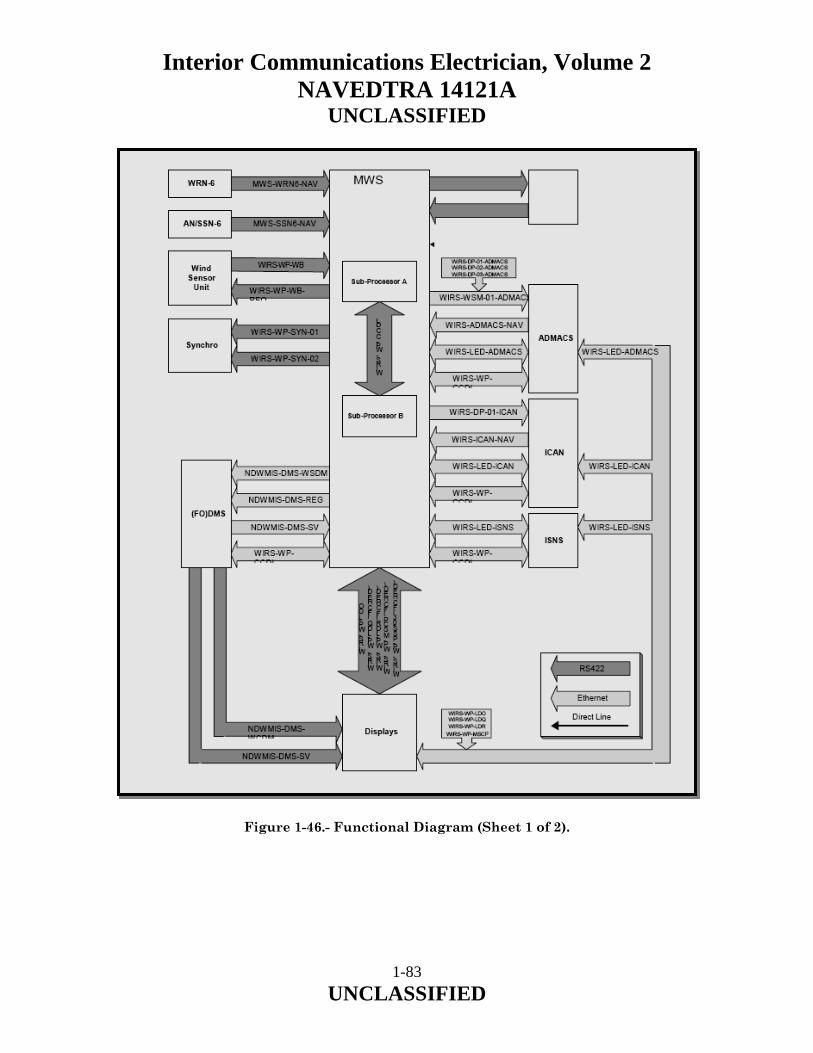
Interior Communications Electrician, Volume 2 NAVEDTRA 14121A
UNCLASSIFIED
Figure 1-46.- Functional Diagram (Sheet 1 of 2).
1-83 UNCLASSIFIED
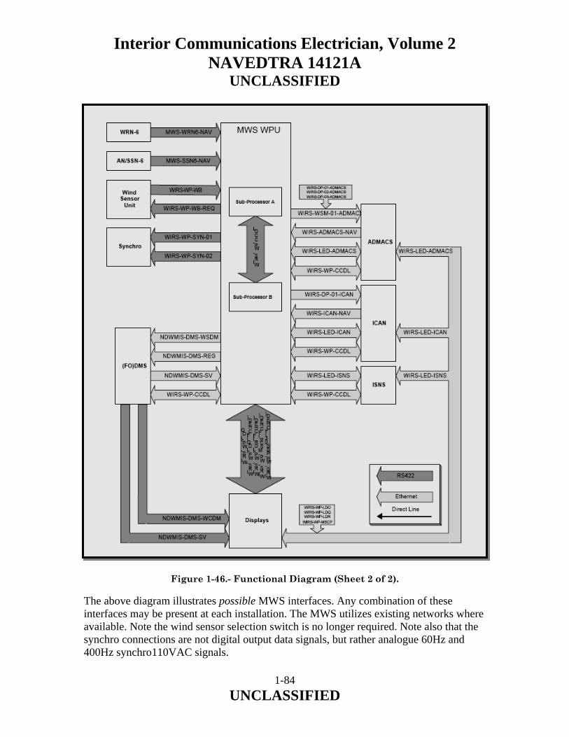
Interior Communications Electrician, Volume 2 NAVEDTRA 14121A
UNCLASSIFIED
Figure 1-46.- Functional Diagram (Sheet 2 of 2). The above diagram illustrates possible MWS interfaces. Any combination of these interfaces may be present at each installation. The MWS utilizes existing networks where available. Note the wind sensor selection switch is no longer required. Note also that the synchro connections are not digital output data signals, but rather analogue 60Hz and 400Hz synchro110VAC signals.
1-84 UNCLASSIFIED

Interior Communications Electrician, Volume 2 NAVEDTRA 14121A
UNCLASSIFIED
Wind Detection The WSU consists of four (4) sensing elements at the top of the unit. Each element is an ultrasonic sensor that can both transmit and receive appropriate signals. The sensing elements consist of two pairs of transducers, mounted at 90º axially to each other, which alternately transmit and receive sound pulses to each other. Measurements are made of the time taken for each pulse to travel to the other sensor. The difference between the times taken for a signal to travel the same path in either direction is used to calculate the wind speed along that axis. The wind speed measured is independent of variations in the velocity of sound. The use of opposite facing ultrasonic sensor orthogonal pairs, provides for good signal/noise ratio, giving the sensor a very high tolerance to rain or other precipitation, as beam energy is concentrated specifically in the axis of each of the sensor pairs. Speed Sensing The component of wind speed between a sensor pair is aided in one direction by any trailing wind and impeded in the other direction. By comparing the sound pulse travel times in both directions, it is possible to determine the wind speed. Direction Sensing By performing trigonometric calculations on the wind speed components in the two orthogonal axes, wind direction is accurately calculated. 1.7.4 Data Distribution The ultrasonic WSU transmits data and test signals via a serial digital interface to the wind processor system unit (WPU) processor. Continually updated wind data is transmitted together with a sensor status code and message check enabling the wind processor to check the validity of the wind data. WPU Dual Redundant Processing The data output lines from the WSUs are connected to both sub processor units (SPUs) within the WPUs through internal wiring. This ensures that the MWS continues to process wind data if one of the SPUs is switched off or fails.
1-85 UNCLASSIFIED

Interior Communications Electrician, Volume 2 NAVEDTRA 14121A
UNCLASSIFIED
WPU Interface Processing There are two types of wind data provided by the WPU to the ships data distribution system: a. Raw data (relative and true) b. Damped data (relative and true) RAW and Damped Data Raw data from the WPU is transmitted to the ships data distribution system for distribution to the ship. To produce sensor output damped data, the WPU processes the raw wind data. The processing function contains a 5° overlap on either side of 0 degrees between sensors. This prevents jitter in the output data when the wind direction is oscillating around the changeover point between port and starboard sensors. A damping filter is also applied to the data to minimize erratic swings in direction and speed caused by gusting winds. This produces damped relative wind data. WPU Processing The WPU is able to automatically identify and select the windward sensor or selected sensor. It damps and processes raw wind data, calculates true wind speed and direction from inputs from the WSUs, ship's speed log and gyro. It then sends the damped wind data to the ships data distribution system in the correct format (ETHERNET T2/FO, RS422 and Synchro) for distribution to the ship’s systems including the navigation and combat system and display units (HEDs and LEDs). Wind Sensor Selection Wind sensor selection is automatically accomplished by the WPU. The active (worker) SPU automatically determines the most windward WSU and selects it as the most accurate. This function is done automatically because WSUs on the leeward side at a particular point in time may be sensing inaccuracies caused by air turbulence around superstructures. The WPU can be manually placed into maintenance mode by the Graphic User Interface (GUI) when the laptop is connected. In this mode, the simulator is active, and any wind sensor can be selected using the laptop. a. Wind Sensor 1 b. Wind Sensor 2 c. Wind Sensor 3 (configured option)
1-86 UNCLASSIFIED

Interior Communications Electrician, Volume 2 NAVEDTRA 14121A
UNCLASSIFIED
d. Wind Sensor 4 (configured option) e. Wind Sensor 5 (configured option) f. Automatic selection In descending order of priority the selection criteria are: a. WPU Maintenance GUI simulator b. Flight Critical High End Display c. WPU automatic selection Dual Redundant WPU The WPU comprises two identical state-of-the-art industrial computer systems designated as Sub Processor Units (SPU) operating in a dual redundant configuration. At any time only one SPU has control of the system. This control can be over-ridden by turning off power to one SPU. During normal operation, the processor at standby mode monitors the performance of the active (worker) SPU. In order to do this, most of the processing of input and output signals is duplicated. If only one sub processor is powered then it automatically becomes the active SPU (worker). Various scenarios involving faults may cause a sub processor changeover to occur. For example if the Standby SPU misses several consecutive status messages from the Active (Worker) SPU across both, the dedicated and network communication paths, this will indicate a fault with the Active (Worker) sub processor and a changeover is initiated. All configuration data is stored in non-volatile memory. This data is consistent across the two SPU. This data is read at WPU startup. If configuration data is altered on a SPU from the maintenance PC, the information is cross-loaded to the other SPU and both SPU are required to be reset to bring the system up utilizing the new information. Wind data from the WPU is fed to both SPU, where it is corrected by comparison to internally stored calibration tables. These can contain correction values for the effects of ship’s superstructure on wind flow around the WSU. A damping filter is also applied to account for sharp, short changes in detected wind speed and direction (i.e., wind gusts). Ship’s heading and speed inputs are then used to modify the relative windward data to produce true wind speed and direction.
1-87 UNCLASSIFIED

Interior Communications Electrician, Volume 2 NAVEDTRA 14121A
UNCLASSIFIED
WPU Data Input/Output Data is received and transmitted by the WPU in various formats depending on the ships systems. The various protocols are described later in this section. Data Inputs The WPU requires ship’s speed and heading data to convert the relative wind data from its orientation referenced to ship’s heading and speed (relative), to true wind data, which has an orientation that is referenced to true north minus the ship’s speed component (true). Ship’s inputs are requested from the ships data distribution system by the WPU. The ship's parameters are passed into the WPU. Data Outputs The WPU transmits the following data out to the Ship’s data interface network: a. Raw relative wind speed and direction data from the WSU b. Damped relative and true wind speed and direction data filtered and calculated by the WPU sensor output damped data, referred to as damped wind, which is damped relative wind data. 1.7.5 Displays The MWS displays are of two types: primarily the High End Display (HED) and Low End Display (LED). FCHED The FCHED is an HED with additional control facilities for selecting any one of the up to five 5 WSUs. It is also used to select the current (worker) SPU. On the status page, two soft key buttons are enabled. One is “sensor”, the other “processor”. Pressing either of these buttons will toggle through the selections. The SPU selection has only three options: Sub-Processor A, Sub-Processor B or automatic selection. As an option, the FCHED is able to provide basic wind direction and speed data in the event of a catastrophic failure of the WPU. When systems include a separately powered WSU, and the RS422 output from it is fed directly to the FCHED, the FCHED is able to select that particular WSU, and receive and display the signals directly. It will only do this if all other inputs have failed. This raw data would enable an airborne aircraft to be recovered in an emergency.
1-88 UNCLASSIFIED

Interior Communications Electrician, Volume 2 NAVEDTRA 14121A
UNCLASSIFIED
HED The High End Display unit receives wind and meteorological data from the WPU. Each page is set to display as much data as is required. Usually several items are displayed on a single page. Displayed data is as follows: a. Relative/true wind speed and direction b. Deck crosswind and headwind (single deck vessels) c. Angled/straight deck crosswind, headwind and tailwind (carrier class (CVN) d. Ships speed and course e. Ships roll and pitch f. Launch and recovery envelops g. Aircraft Recovery Bulletins (aircraft carriers only) h. Fox Corpen information (i.e., computation of ships speed and course to achieve a wind speed and direction to safely land an aircraft). i. MWS health status indication HED Processing Function The HED functions are managed by a high speed processor. A LINUX operating system is used and serial communication is at standard baud rates up to 38,400, using an Ethernet interface 100 BaseFx or RS422 10Base2. The processor controls all the functions required to store, distribute and display wind-related data, and calculates Fox Corpen from the true wind and wind envelope. Parameters for each type of aircraft employed on the ship (wind envelope pages) may be downloaded using the GUI with a standard Laptop PC. By the same means, the required display pages may be selected, and their sequential order changed and stored in a non-volatile memory. Built In Test Equipment (BITE) The HED has built-in test (BIT) facilities for display checking, memory testing and other self test. BIT Mode is automatically initiated at each power up. Diagnostic fault messages are provided on the display.
1-89 UNCLASSIFIED

Interior Communications Electrician, Volume 2 NAVEDTRA 14121A
UNCLASSIFIED
HED Fault Indication The presence of data from any of the enabled inputs (dual redundant configuration), or a single input is provided for every accessible page of data. To alert the crew if data is lost or unavailable, numeric and text data is scored across with a thick Red bar, dial pointers removed, and bar indicators are filled Red. Alert messages are displayed. In addition, where the serial input message contains specific status information, a status page is available, to give full fault data. This reports the status of each of the MWS component units and ships data. Watchdog A built in watchdog timer automatically reboots the display in approximately 30 seconds, if it detects a lack of processor activity. This is precautionary step to prevent a “frozen” display and is not expected to be a regular occurrence. In addition an activity indicator is displayed in the form of a moving blue square at the lower Left Hand corner of each HED/LED. VSTOL and Helicopter Launch and Recovery Envelopes A wind envelope is a polar plot of wind speed and direction limits acceptable to land an aircraft on board ship. Providing the wind speed and direction vector lies within the polar diagram envelope, a safe landing is possible. The polar diagram changes according to the ship type, and aircraft type, as well as other parameters including roll, pitch, helicopter weight and deck cursor. The selection method employs a tiered menu, selectable with soft-keys, allowing the crew to select a diagram, based on a sequence of decisions. The technique allows a large number of diagrams to be retained by the system, and allows for an efficient selection based on the criteria given below. a. Aircraft type b. Aircraft load category c. Aircraft direction of approach/takeoff d. Day/Night or Standby time e. Sea conditions (based on historical roll and pitch data) f. Deck cursor or landing platform (for ships with more than one landing site)
1-90 UNCLASSIFIED

Interior Communications Electrician, Volume 2 NAVEDTRA 14121A
UNCLASSIFIED
Aircraft Recovery Bulletins The aircraft recovery bulletins are tables of valve settings for the recovery of fixed wing aircraft. These tables are stored on a server on the ship’s network ADMACS system in the form of JPEG files. The Server makes these available to the HED. They are only available for ships with an ADMACS installed. The initial selection on the HED is by a particular aircraft type. Detailed selection then depends on the recovery system being employed. The JPEG files are viewed as a page. Fox Corpen When the wind and other weather conditions do not allow flight operation within an acceptable envelope, facilities are provided on the display units to compute an alternative ships course and/or speed. Using the function keys provided to move a cursor (or the use of the external pointer option), until a preferred wind vector is selected and shown on the display. The system automatically computes the required ships heading and speed to achieve the required vector. This is referred to as Fox Corpen data and there can be one, two, or no solutions to the computations. When there are two solutions, one is known as the high-speed solution and the other as the low speed solution. The display units will present both solutions. The high-speed solution could easily be removed, but the decision is based on maximum ships speed which may be classified information. Roll and Pitch The ships roll and pitch amplitudes govern whether flight operations can be carried out. The envelope page displays the roll and pitch using either standard deviation calculation, or sliding peak value. When the maximum permitted, value is exceeded then the wind cursor is displayed as red independent of the wind speed. If the peak option is chosen then the number of samples is a further option. There is a manual peak reset mode where the peak is cleared by pressing a soft key rather than when the peak value leaves the sliding data window. The roll and pitch instantaneous values are displayed on a separate page, and updated constantly. LED The Low End Display (LED) receives wind and other ship sensor data from the WPU and displays data in the following formats: a. Relative/True Wind Speed and Direction b. Deck Crosswind and Headwind (single deck vessels)
1-91 UNCLASSIFIED

Interior Communications Electrician, Volume 2 NAVEDTRA 14121A
UNCLASSIFIED
c. Angled/Straight Deck Crosswind, Headwind and Tailwind (aircraft carriers only) d. Ship's Speed and Course e. Ship's Roll and Pitch f. MWS health Status LED Processing Function The LED uses the same hardware and operating system as the HED. The only difference is the number of pages stored and readily accessed. These are configured at the factory or on-board the ship at installation. Possible Configurable items include: a. Fixed angle deck cross and head wind display b. Fixed straight deck cross and head wind display c. Units for all data (meter per second to knots and millibars, to inches of Hg) Built In Test Equipment (BITE) The LED BITE is identical to that described for the HED. Aircraft Launch and Recovery Envelopes These are normally provided by the HED facilities. Roll and Pitch The ships roll and pitch amplitudes govern whether flight operations are permissible. The LED computes roll and pitch and functions the same as the HED. 1.7.6 Power Supply for HED and LED Power supply arrangements for both types of display are identical. A single phase of 115VAC is the normal input. The HED and LED receive power on P1 where: a. Pin A L1 b. Pin B L2 c. Pin C Ground
1-92 UNCLASSIFIED

Interior Communications Electrician, Volume 2 NAVEDTRA 14121A
UNCLASSIFIED
WPU Power Supplies The power input for each Sub-Processor enters the WPU via a separate connector J21 or J22. The connector J21 feeds the SPU Sub-Processor “A” power supply unit and the associated 24VDC supply to power the wind sensors. J22 powers APU Sub-Processor “B” and its 24VDC wind sensor supply. Each input power line is fed through a separate power filter to the individual power switch and fuse. Power Supply Options There are two options for the power supply: dual 115VAC feeds or single 115VAC feed with 115VAC UPS backup. Both options are explained below. Dual 115VAC Feed The system receives dual 115VAC feeds from separate ship power sources. Subprocessor-Processor Power Supply Each SPU has a self-contained PSU providing supply for its own operation. The input can be either 115VAC. The power supply produces +5VDC and +/-12VDC supplies, which are fed directly to the sub processor motherboard. Fuse Protection All power inputs and DC outputs are protected by fuses on the front panel of the WPU and on the underside of the HED/LED. There are additional fuses in the WPU to protect the 24v DC PSU. Each of the power supplies for the WSU and backup 24VDC is fed from separate fuses within the WPU. The 24VDC is fed power through the terminal block mounted on the side of the transformer. This terminal block can be wired in different ways. It is factory set to have 115VAC as its input. It can be changed at the factory to accept 230 VAC. The outputs of both 24VDC supplies are cross connected through diodes, the output feeding the power output from the RS422 and power connectors, through suitable fuses. Cooling Fans Overheating protection is provided by the two fans. These are mounted on either side of the WPU. Each provides a tachometer output that is monitored by the built in test. Loss of this signal forces the SPU into degraded mode. WPU Power Supply BITE The outputs from both the 24VDC power supplies and the SPU PSUs are monitored by the WPU built in test equipment. The green indicators LED’s on the front panel indicate the status of each supply.
1-93 UNCLASSIFIED

Interior Communications Electrician, Volume 2 NAVEDTRA 14121A
UNCLASSIFIED
1.7.7 Uninterruptible Power Supply (UPS) The UPS provides continuous power to maintain the MWS functions for a period of 15 minutes. It also filters out minor fluctuations of the normal power supply, and isolates it from large disturbances. The UPS performs a self-test when the MWS is turned on, and every two weeks thereafter. A self test can also be manually performed by pressing Test button for a few seconds. Depressing the Test button activates a column of five indicator LEDs to indicate the power voltage (VAC) as incremental steps as follows:
• 133 • 124 • 114 • 105 • 96
When the supply is at 115VAC, the bottom three indicators are lit. External 28VDC Power Supply Unit (PSU) The external 28VDC power supply provides a separate source of 28VDC power supply to a WSU. It is used in ship installations where a particular WSU is located too far away from the WPU to be directly powered by the WPU. The external PSU provides 28VDC power to the WSU components, as well as powering the WSU heaters in cold weather conditions. 1.7.8 Data Communications The following paragraphs describe the data communication system between components of the MWS and the transfer of data to and from the data network for use by other ship dependent systems and MWS. Refer to Figure 1-46 for an overview. Data transfers throughout the MWS use standard open architecture LAN and serial RS422 interfaces. The MWS has been designed to be compatible with data transfer system used in the U.S. Navy ships.
1-94 UNCLASSIFIED
Interior Communications Electrician, Volume 2 NAVEDTRA 14121A
UNCLASSIFIED
WSU Output Protocol Each WSU supplies an RS422 asynchronous serial data stream to the WPU. The data is updated at 10 Hz. The basic rate is as follows: 9600 – 19200 Baud (9600 as standard) 8 data bits Even parity LSB sent first Update rate 10 Hz Variable averaging is not set Units m/s. WPU Data Protocols This paragraph describes the interface protocol and format requirements of the Moriah Wind System (MWS) and other systems aboard ship. It also defines message contents on external WPU interfaces. This is applicable to all installations that incorporate any of the following interfaces: a. (Fiber Optic) Data Multiplex System (FO) DMS b. Navigation Sensor System Interface (NAVSSI) c. Aviation Data Management and Control System (ADMACS) d. High End Display (HED) e. Low End Display (LED) f. Synchro Interface for Legacy Systems g. Wind Sensor Unit (WSU) h. Inter-Processor Communication (IPC)
1-95 UNCLASSIFIED

Interior Communications Electrician, Volume 2 NAVEDTRA 14121A
UNCLASSIFIED
The following interface information is in the order shown above. Additional useful information on unlisted items is at the end of these paragraphs. (FO) DMS Interface (FO) DMS interface (Aegis Destroyers) supplies ship’s data for speed, heading, roll and pitch and an interface to distribute wind speed and wind direction. The (FO) DMS network (if available) is also utilized for inter-processor communication. MWS does not transmit wind data directly to the LEDs and HEDs; they actually register as wind data clients to receive wind data via (FO) DMS. NAVSSI Interface This transfers a standard navigational message of ships behavior and direction and is sent via the ship’s data network server, ICAN or ADMACS LAN interfaces. ADMACS Interface The ADMACS interface (aircraft carriers only) provides a means of supplying ADMACS with both wind data calculated/processed by MWS and specific meteorological data that MWS receives via the SMOOS(R) interface. The ADMACS Network is also used for transferring information to displays and for inter-processor communication (IPC). NAVSSI data corresponding to ship’s course, speed, heading, roll and pitch is received over the ADMACS network). WPU to HED Interface The HED interface is either by a dedicated RS422 serial line, or by the ship’s data network. Details are given in the HED data communications. LED Interface The LED interface is identical to the HED. HED Data Communications The Flight Critical HED (FCHED) has a dedicated RS422 serial interface directly to the WPU. In an emergency situation other HEDs and LEDs can also be connected to the WPU via a serial RS422 interface. In normal operations the HEDs and LEDs are interfaced with the WPU via the ship’s data network server. There are four types of data: a) a general message describing the ship and the MWS status, b) a query as to the status of the receiving display, c) the response from that display, and d) the controlling messages to change the WSU/WPU selection.
1-96 UNCLASSIFIED
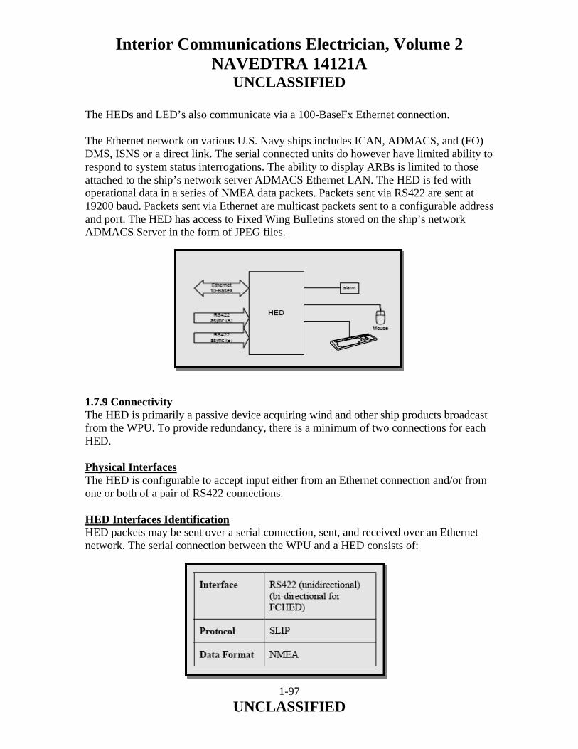
Interior Communications Electrician, Volume 2 NAVEDTRA 14121A
UNCLASSIFIED
The HEDs and LED’s also communicate via a 100-BaseFx Ethernet connection. The Ethernet network on various U.S. Navy ships includes ICAN, ADMACS, and (FO) DMS, ISNS or a direct link. The serial connected units do however have limited ability to respond to system status interrogations. The ability to display ARBs is limited to those attached to the ship’s network server ADMACS Ethernet LAN. The HED is fed with operational data in a series of NMEA data packets. Packets sent via RS422 are sent at 19200 baud. Packets sent via Ethernet are multicast packets sent to a configurable address and port. The HED has access to Fixed Wing Bulletins stored on the ship’s network ADMACS Server in the form of JPEG files. 1.7.9 Connectivity The HED is primarily a passive device acquiring wind and other ship products broadcast from the WPU. To provide redundancy, there is a minimum of two connections for each HED. Physical Interfaces The HED is configurable to accept input either from an Ethernet connection and/or from one or both of a pair of RS422 connections. HED Interfaces Identification HED packets may be sent over a serial connection, sent, and received over an Ethernet network. The serial connection between the WPU and a HED consists of:
1-97 UNCLASSIFIED
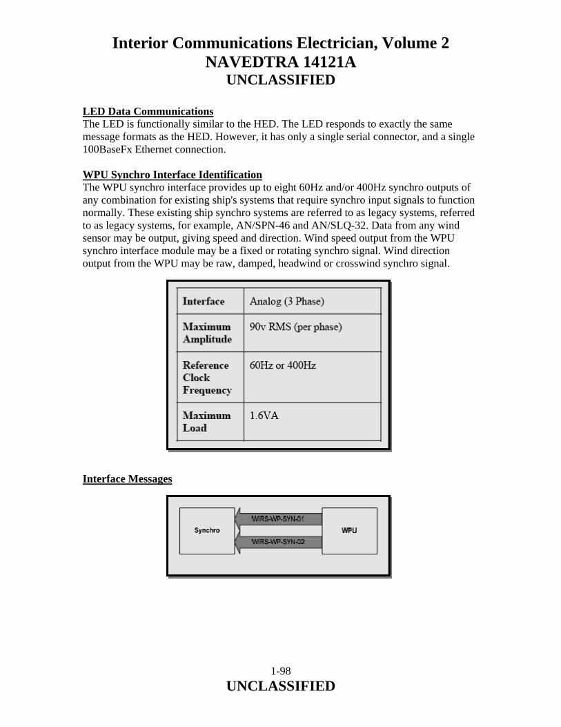
Interior Communications Electrician, Volume 2 NAVEDTRA 14121A
UNCLASSIFIED
LED Data Communications The LED is functionally similar to the HED. The LED responds to exactly the same message formats as the HED. However, it has only a single serial connector, and a single 100BaseFx Ethernet connection. WPU Synchro Interface Identification The WPU synchro interface provides up to eight 60Hz and/or 400Hz synchro outputs of any combination for existing ship's systems that require synchro input signals to function normally. These existing ship synchro systems are referred to as legacy systems, referred to as legacy systems, for example, AN/SPN-46 and AN/SLQ-32. Data from any wind sensor may be output, giving speed and direction. Wind speed output from the WPU synchro interface module may be a fixed or rotating synchro signal. Wind direction output from the WPU may be raw, damped, headwind or crosswind synchro signal. Interface Messages
1-98 UNCLASSIFIED

Interior Communications Electrician, Volume 2 NAVEDTRA 14121A
UNCLASSIFIED
1-99 UNCLASSIFIED
1.7.10 Legacy Wind Raw (WIRS-WP-SYN-01) This consists of analog data representing raw wind direction and speed: a. Raw Wind Direction - Phase angle indicating wind direction. b. Raw Wind Speed - Rate of Turn Wind Speed 1.7.11 Legacy Wind Dampened (WIRS-WP-SYN-02) This consists of analog data representing damped wind direction and speed: a. Damped Wind Direction - Phase angle indicating wind direction. b. Damped Wind Speed - Phase angle indicating wind speed. 1.8.0 SUMMARY In this chapter, we have described the purpose of Synchros, Synchro Maintenance and Troubleshooting and Wind Systems. We have identified and discussed the operation of Anemometers, Crosswind and Headwind Computer Assembly and Speed Indicator. We have identified and discussed the operation of some of the various Wind systems installed on Navy ships including Digital Wind System and Moriah Wind System. We have briefly discussed some of the preventive and corrective maintenance measures associated with Synchros, Amplifiers and Wind and Speed Indicating Systems.
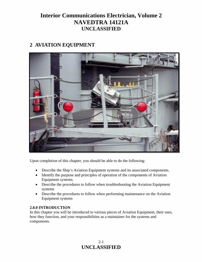
Interior Communications Electrician, Volume 2 NAVEDTRA 14121A
UNCLASSIFIED
2 AVIATION EQUIPMENT Upon completion of this chapter, you should be able to do the following:
• Describe the Ship’s Aviation Equipment systems and its associated components. • Identify the purpose and principles of operation of the components of Aviation
Equipment systems. • Describe the procedures to follow when troubleshooting the Aviation Equipment
systems • Describe the procedures to follow when performing maintenance on the Aviation
Equipment systems 2.0.0 INTRODUCTION In this chapter you will be introduced to various pieces of Aviation Equipment, their uses, how they function, and your responsibilities as a maintainer for the systems and components.
2-1 UNCLASSIFIED

Interior Communications Electrician, Volume 2 NAVEDTRA 14121A
UNCLASSIFIED
2.1.0 STABILIZED GLIDE SLOPE INDICATOR (SGSI) SYSTEM The stabilized glide slope indicator (SGSI) system consists of a GSI cell mounted on top of an electrohydraulic stabilized platform. The GSI cell is an optical viewing system used to indicate to a pilot the aircraft approach angle to a landing platform or ship. The GSI system is an electrohydraulic optical landing aid designed for use on ships equipped for helicopter operations. By use of the SGSI, a helicopter pilot may visually establish and maintain the proper glide slope for a safe landing. The system is self-contained, relying on the ship for 115 volts ac 400-Hz and 440 volts ac 60-Hz power. The GSI, which is mounted on a stable platform, provides a single bar of light either green, amber, or red (fig. 2-1). The cell face acts as a window through which the pilot views the light. The color of the light bar indicates to the pilot of the approaching aircraft whether the aircraft is above (green), below (red), or on (amber) the correct glide slope. By varying the aircraft altitude to keep the amber light bar visible, the pilot maintains the correct glide path to the ship’s landing pad. The bar of light is formed by the combined actions of source light, Fresnel lens, and lenticular lens. Figure 2-1.-Glide slope indicator and light beam. To steady the GSI with respect to the pitching and rolling motions of the ship, the light cell is mounted on an electrohydraulic stabilized platform. This equipment uses a local gyro for reference and develops electronic error signals that, in turn, control hydraulic cylinders that move the platform in the opposite direction to the ship’s pitch and roll axis. The system incorporates a failure detection circuit that turns off the lights in the event of stabilization failure.
2-2 UNCLASSIFIED

Interior Communications Electrician, Volume 2 NAVEDTRA 14121A
UNCLASSIFIED
2.1.1 SGSI System Components The assemblies that comprise the SGSI system are as follows (fig. 2-2):
• Electronic enclosure assembly • Remote control panel assembly • Hydraulic pump assembly • Transformer assembly • GSI assembly • Stabilized platform assembly
2-3 UNCLASSIFIED
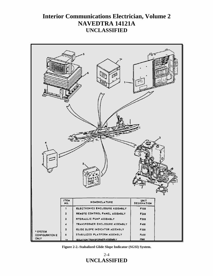
Interior Communications Electrician, Volume 2 NAVEDTRA 14121A
UNCLASSIFIED
Figure 2-2.-Stabalized Glide Slope Indicator (SGSI) System.
2-4 UNCLASSIFIED

Interior Communications Electrician, Volume 2 NAVEDTRA 14121A
UNCLASSIFIED
Electronics Enclosure Assembly The electronics enclosure assembly (fig. 2-3) is the signal processing distribution and control center for the system. It contains the circuits, amplifiers, and other electrical and electronic components required to control the major components of the system. Figure 2-3.-Electronics Enclosure Assembly (F100).
2-5 UNCLASSIFIED
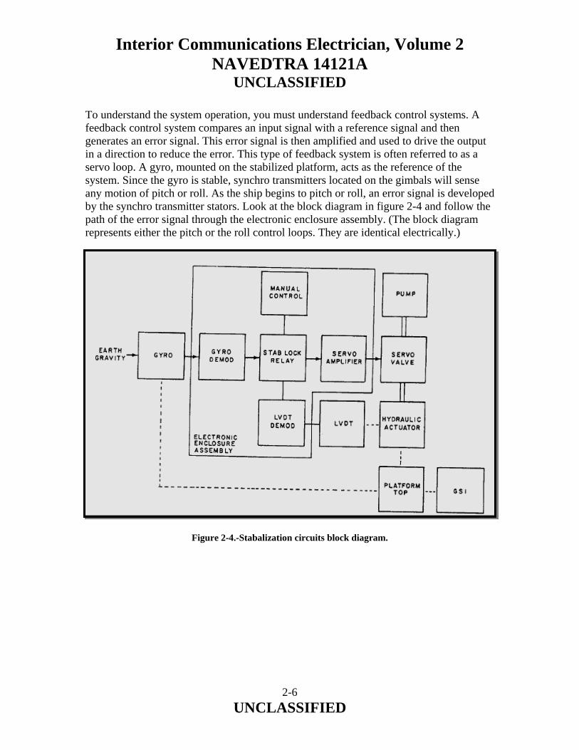
Interior Communications Electrician, Volume 2 NAVEDTRA 14121A
UNCLASSIFIED
To understand the system operation, you must understand feedback control systems. A feedback control system compares an input signal with a reference signal and then generates an error signal. This error signal is then amplified and used to drive the output in a direction to reduce the error. This type of feedback system is often referred to as a servo loop. A gyro, mounted on the stabilized platform, acts as the reference of the system. Since the gyro is stable, synchro transmitters located on the gimbals will sense any motion of pitch or roll. As the ship begins to pitch or roll, an error signal is developed by the synchro transmitter stators. Look at the block diagram in figure 2-4 and follow the path of the error signal through the electronic enclosure assembly. (The block diagram represents either the pitch or the roll control loops. They are identical electrically.) Figure 2-4.-Stabalization circuits block diagram.
2-6 UNCLASSIFIED
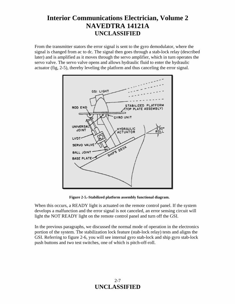
Interior Communications Electrician, Volume 2 NAVEDTRA 14121A
UNCLASSIFIED
From the transmitter stators the error signal is sent to the gyro demodulator, where the signal is changed from ac to dc. The signal then goes through a stab-lock relay (described later) and is amplified as it moves through the servo amplifier, which in turn operates the servo valve. The servo valve opens and allows hydraulic fluid to enter the hydraulic actuator (fig, 2-5), thereby leveling the platform and thus canceling the error signal. Figure 2-5.-Stabilized platform assembly functional diagram. When this occurs, a READY light is actuated on the remote control panel. If the system develops a malfunction and the error signal is not canceled, an error sensing circuit will light the NOT READY light on the remote control panel and turn off the GSI. In the previous paragraphs, we discussed the normal mode of operation in the electronics portion of the system. The stabilization lock feature (stab-lock relay) tests and aligns the GSI. Referring to figure 2-6, you will see internal gyro stab-lock and ship gyro stab-lock push buttons and two test switches, one of which is pitch-off-roll.
2-7 UNCLASSIFIED
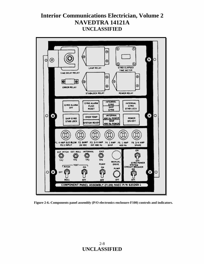
Interior Communications Electrician, Volume 2 NAVEDTRA 14121A
UNCLASSIFIED
Figure 2-6.-Components panel assembly (P/O electronics enclosure-F100) controls and indicators.
2-8 UNCLASSIFIED
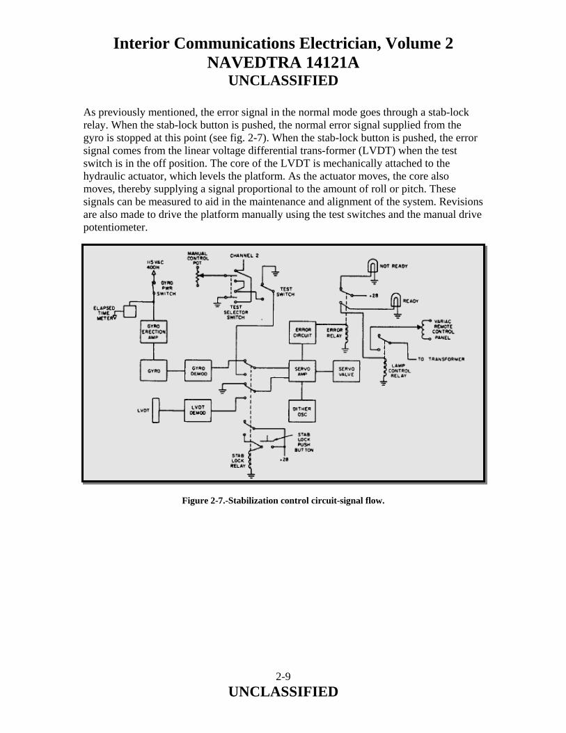
Interior Communications Electrician, Volume 2 NAVEDTRA 14121A
UNCLASSIFIED
As previously mentioned, the error signal in the normal mode goes through a stab-lock relay. When the stab-lock button is pushed, the normal error signal supplied from the gyro is stopped at this point (see fig. 2-7). When the stab-lock button is pushed, the error signal comes from the linear voltage differential trans-former (LVDT) when the test switch is in the off position. The core of the LVDT is mechanically attached to the hydraulic actuator, which levels the platform. As the actuator moves, the core also moves, thereby supplying a signal proportional to the amount of roll or pitch. These signals can be measured to aid in the maintenance and alignment of the system. Revisions are also made to drive the platform manually using the test switches and the manual drive potentiometer. Figure 2-7.-Stabilization control circuit-signal flow.
2-9 UNCLASSIFIED

Interior Communications Electrician, Volume 2 NAVEDTRA 14121A
UNCLASSIFIED
Remote Control Panel Assembly The remote control panel (fig. 2-8) is located in the flight operations control room. The panel provides control and indicators for operating and monitoring the SGSI system from a remote location. It contains the READY and NOT READY lights described previously. The panel also contains an OVERTEMP light to indicate when the hydraulic fluid is heated to a temperature higher than 135°F±5°, a source failure light to indicate that one or more of the GSI source lights are burned out, a variable transformer to control the intensity of GSI light, and a panel illumination control. A standby light will be energized when the main switch on the electronic enclosure assembly is on. Figure 2-8.-Remote Control Panel Assembly (F200).
2-10 UNCLASSIFIED

Interior Communications Electrician, Volume 2 NAVEDTRA 14121A
UNCLASSIFIED
Hydraulic Pump Assembly The hydraulic pump assembly (fig. 2-9) is a self contained medium-pressure, closed-loop system used to supply hydraulic pressure for the stabilized platform. This assembly consists of an electric pump motor, a coupling unit, a hydraulic pump reservoir, valves, piping, and an electrical system. All components are mounted on a steel base with isolation mounts and comprise a complete self contained 1400-psi hydraulic power supply.
Figure 2-9.-Hydraulic Pump Assembly (F300).
2-11 UNCLASSIFIED

Interior Communications Electrician, Volume 2 NAVEDTRA 14121A
UNCLASSIFIED
Hydraulic fluid is stored in a reservoir and piped to a motor-driven pump. The output is pressurized by the pump to 1400 psi, filtered, and piped to the power supply output line where it is available to the external system through a shutoff valve. On the return line, fluid is returned from the external system to the reservoir at a reduced pressure of 75 psi. A shutoff valve is also used in this low-pressure line. Electrical power is obtained from ship’s power system and connected through the motor controller and junction box. This assembly is located as close as possible to the stabilized platform. It provides hydraulic fluid at 1400 psi to the hydraulic actuator on the stabilized platform. The motor and controller operate on 440-volt, 3-phase received from normal ship’s power supply. The temperature switches (not shown) operate the OVERTEMP light on the remote control panel. Also, a pressure switch in the hydraulic pump discharge line will close at 1200 psi. If not closed, the pressure switch will de-energize the electronic panel assembly on low oil pressure. Hydraulic fluid heaters in the oil reservoir maintain the temperature at approximately 70°F±5°. Transformer Assembly The transformer assembly is a weather tight enclosure mounted within 3 feet of the stabilized platform. An interconnecting cable, which is part of the transformer assembly, connects the transformer assembly to the GSI. This assembly is located as close as possible to the stabilized platform. Its purpose is to step down the voltage for the source light (GSI) from 115 volts ac to 18.5 volts ac. Glide Slope Indicator Assembly The GSI assembly consists of two major subassemblies: the mounting base assembly and the indicator assembly. The indicator assembly is supported in the mounting base assembly, which is mounted on the stabilized platform. The incoming system cable connects at the rear of the right-hand heater compartment. The mounting base assembly provides the means to accurately position the indicator assembly in relation to the landing pad. The mounting base is then secured in this position by the retractable plunger. Indicator elevation is controlled by the elevation adjustment knob. The GSI sits in the trunnions of the mounting base assembly. Stabilized Platform Assembly The stabilized platform assembly is mounted to the ship’s deck in close proximity to the helicopter landing area. This assembly contains a local gyro, gimbaled platform, hydraulic cylinders, and electrically operated servo valves. More information on the stabilized platform is given later in this chapter.
2-12 UNCLASSIFIED
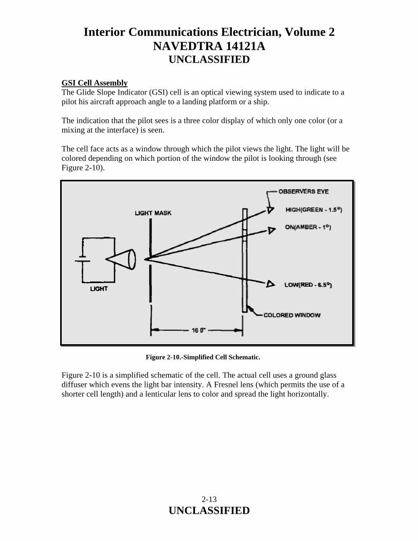
Interior Communications Electrician, Volume 2 NAVEDTRA 14121A
UNCLASSIFIED
GSI Cell Assembly The Glide Slope Indicator (GSI) cell is an optical viewing system used to indicate to a pilot his aircraft approach angle to a landing platform or a ship. The indication that the pilot sees is a three color display of which only one color (or a mixing at the interface) is seen. The cell face acts as a window through which the pilot views the light. The light will be colored depending on which portion of the window the pilot is looking through (see Figure 2-10). Figure 2-10.-Simplified Cell Schematic. Figure 2-10 is a simplified schematic of the cell. The actual cell uses a ground glass diffuser which evens the light bar intensity. A Fresnel lens (which permits the use of a shorter cell length) and a lenticular lens to color and spread the light horizontally.
2-13 UNCLASSIFIED

Interior Communications Electrician, Volume 2 NAVEDTRA 14121A
UNCLASSIFIED
Figure 2-11 is a simplified functional diagram of the GSI as it appears in the system. The action of this cell is exactly the same as that described in Figure 2-10.
Figure 2-11.-Glide Slope Indicator, Simplified Functional Diagram. The cell is usually set on a three degree glide slope as its red/amber intersection and it has a horizontal coverage of forty degrees (see Figure 2-12).
2-14 UNCLASSIFIED
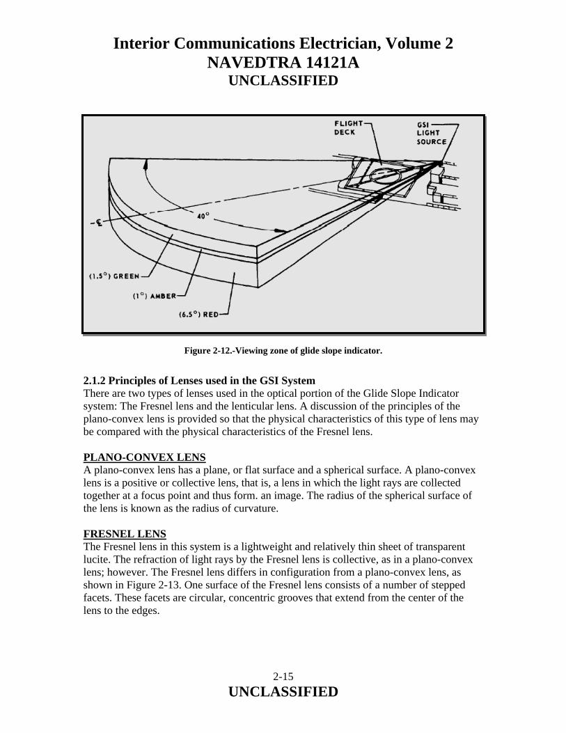
Interior Communications Electrician, Volume 2 NAVEDTRA 14121A
UNCLASSIFIED
Figure 2-12.-Viewing zone of glide slope indicator. 2.1.2 Principles of Lenses used in the GSI System There are two types of lenses used in the optical portion of the Glide Slope Indicator system: The Fresnel lens and the lenticular lens. A discussion of the principles of the plano-convex lens is provided so that the physical characteristics of this type of lens may be compared with the physical characteristics of the Fresnel lens. PLANO-CONVEX LENS A plano-convex lens has a plane, or flat surface and a spherical surface. A plano-convex lens is a positive or collective lens, that is, a lens in which the light rays are collected together at a focus point and thus form. an image. The radius of the spherical surface of the lens is known as the radius of curvature. FRESNEL LENS The Fresnel lens in this system is a lightweight and relatively thin sheet of transparent lucite. The refraction of light rays by the Fresnel lens is collective, as in a plano-convex lens; however. The Fresnel lens differs in configuration from a plano-convex lens, as shown in Figure 2-13. One surface of the Fresnel lens consists of a number of stepped facets. These facets are circular, concentric grooves that extend from the center of the lens to the edges.
2-15 UNCLASSIFIED
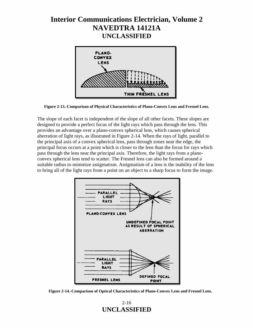
Interior Communications Electrician, Volume 2 NAVEDTRA 14121A
UNCLASSIFIED
Figure 2-13.-Comparison of Physical Characteristics of Plano-Convex Lens and Fresnel Lens. The slope of each facet is independent of the slope of all other facets. These slopes are designed to provide a perfect focus of the light rays which pass through the lens. This provides an advantage over a plano-convex spherical lens, which causes spherical aberration of light rays, as illustrated in Figure 2-14. When the rays of light, parallel to the principal axis of a convex spherical lens, pass through zones near the edge, the principal focus occurs at a point which is closer to the lens than the focus for rays which pass through the lens near the principal axis. Therefore, the light rays from a plano-convex spherical lens tend to scatter. The Fresnel lens can also be formed around a suitable radius to minimize astigmatism. Astigmatism of a lens is the inability of the lens to bring all of the light rays from a point on an object to a sharp focus to form the image.
Figure 2-14.-Comparison of Optical Characteristics of Plano-Convex Lens and Fresnel Lens.
2-16 UNCLASSIFIED

Interior Communications Electrician, Volume 2 NAVEDTRA 14121A
UNCLASSIFIED
The optical characteristics of the Fresnel lens will vary with a change in temperature. If the lens temperature is allowed to vary, three effects will be observed. First, if the temperature varies, the size of the bar of light near the center of the lens is different from that which is seen near the center of the lens when the lens is at design temperature. Also, as the observer moves up or down, the size of the bar of light appears to change as the image moves from the lens center. The second effect that will be observed is that the bar will have a more noticeable bend when the lens is not at design temperature. The last effect that will be observed is that the vertical field angle is larger when the ambient temperature is higher than design temperature and smaller when the ambient temperature is lower than the design temperature (Figure 2-15). To maintain design characteristics of the Fresnel lens. The lens-heating compartments are maintained at a temperature which is relatively constant. The Fresnel lens is enclosed in a separate compartment in which the lenticular lens serves as the front and an optical glass serves as the back of the compartment. Hot air is circulated in the compartment under thermostatic control. Figure 2-15.-Vertical Field Angle.
2-17 UNCLASSIFIED
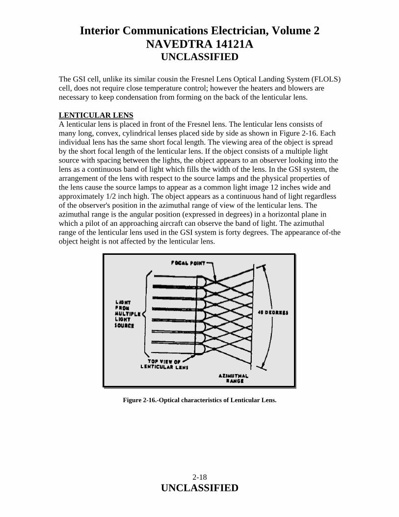
Interior Communications Electrician, Volume 2 NAVEDTRA 14121A
UNCLASSIFIED
The GSI cell, unlike its similar cousin the Fresnel Lens Optical Landing System (FLOLS) cell, does not require close temperature control; however the heaters and blowers are necessary to keep condensation from forming on the back of the lenticular lens. LENTICULAR LENS A lenticular lens is placed in front of the Fresnel lens. The lenticular lens consists of many long, convex, cylindrical lenses placed side by side as shown in Figure 2-16. Each individual lens has the same short focal length. The viewing area of the object is spread by the short focal length of the lenticular lens. If the object consists of a multiple light source with spacing between the lights, the object appears to an observer looking into the lens as a continuous band of light which fills the width of the lens. In the GSI system, the arrangement of the lens with respect to the source lamps and the physical properties of the lens cause the source lamps to appear as a common light image 12 inches wide and approximately 1/2 inch high. The object appears as a continuous hand of light regardless of the observer's position in the azimuthal range of view of the lenticular lens. The azimuthal range is the angular position (expressed in degrees) in a horizontal plane in which a pilot of an approaching aircraft can observe the band of light. The azimuthal range of the lenticular lens used in the GSI system is forty degrees. The appearance of-the object height is not affected by the lenticular lens.
Figure 2-16.-Optical characteristics of Lenticular Lens.
2-18 UNCLASSIFIED

Interior Communications Electrician, Volume 2 NAVEDTRA 14121A
UNCLASSIFIED
The lenticular lens in the GSI assembly is manufactured with three different color segments to eliminate the need for filters and their subsequent light attenuation. The top segment is colored green, the middle is amber and the large bottom segment is red. When projected, the resulting glide path has the viewing zone shown in Figure 2-12. The GSI cell was designed so one inch on its face is equal to one degree of arc. Thus the one degree amber is one inch on the cell face. The stowlock assembly provides a means of securing the source light indicator in a fixed position when the system is not in operation. The stowlock assembly is located directly below the source light indicator assembly and is secured to the deck-edge boom. The shipbuilder’s junction box is used as a junction point for various cables of the system, as are all junction boxes that are a part of the system. 2.1.3 System Operation, Troubleshooting, and Maintenance The following paragraphs provide information on operating, checking-out, troubleshooting, and maintaining the SGSI system. We will discuss some of the things that can be done to keep the SGSI operating efficiently. When troubleshooting the SGSI system, you should refer to the troubleshooting charts in the Stabilized Glide Slope Indicator (SGSI) Mk 1 Mod 0 (Incorporating Gyro Failure Alarm) for Air Capable and Amphibious Assault Ships, NAVAIR 51-5B-2, technical manual. By using the charts/tables in the technical manual for overall system checkout procedures, you will know what controls must be set during the performance of the checkout procedure. These tables also list the location of each control, the necessary instructions for the proper use of these controls, and the normal indications that should be observed during the operation of these controls. When an abnormal indication is observed during the checkout procedures, certain additional procedures must be performed that use the controls available within the equipment to establish conditions that enable maintenance personnel to isolate malfunctions with a minimum use of test equipment. By using these procedures, you can locate the cause of the specific malfunction and perform the recommended corrective maintenance. Maintenance is an ongoing process to keep the equipment operating efficiently and consists of preventive and corrective maintenance. For all maintenance requirements for the SGSI system, you should refer to the maintenance requirement cards (MRCs). There are maintenance items to be performed weekly, quarterly, semiannually, and annually. System maintenance must be performed on a regular basis regardless of use cycle. Deterioration and/or damage to equipment may result if system maintenance is not performed regularly. The information given in the following paragraphs is not intended to replace preventive maintenance cards or the applicable technical manuals. This information should familiarize you with some of the requirements and procedures to keep the equipment in top notch operating condition.
2-19 UNCLASSIFIED

Interior Communications Electrician, Volume 2 NAVEDTRA 14121A
UNCLASSIFIED
Gyro Alarm Off If a failure occurs in the error sensing circuitry or if the ship’s gyro information or gyro reference voltage is not being sent to the SGSI, a ready light cannot be obtained. This will keep the lamp relay de-energized and not allow the source lamps to illuminate. Operation in the internal gyro mode is still possible through the activation of the gyro alarm off switch-indicator on the component panel assembly. Since the gyro alarm off switch-indicator disables the independent failure detection circuit, a gyro alarm off indicator is automatically illuminated in both the electronic enclosure and the remote control panel. Servo error sensing is not affected by activation of gyro alarm off. Depressing the gyro alarm off push button will activate the ready light and allow the source lamps to illuminate if no other system problems exist. Gyro Failure Alarm Circuit Tests These tests are to be performed once a week when the SGSI is being used for air operations. These tests will ensure that all failure monitoring circuits are operational. Vertical Gyroscope The vertical gyroscope is basically a mechanical device. The essential element of the gyroscope is a flywheel rotating at high angular velocity about an axis. The flywheel is mounted within gimbals that allow it two degrees of freedom as shown in figure 2-17. Figure 2-17.-Vertical gyro, simplified schematic.
2-20 UNCLASSIFIED
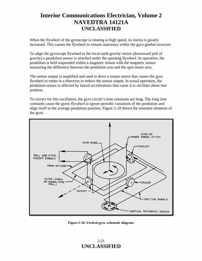
Interior Communications Electrician, Volume 2 NAVEDTRA 14121A
UNCLASSIFIED
When the flywheel of the gyroscope is rotating at high speed, its inertia is greatly increased. This causes the flywheel to remain stationary within the gyro gimbal structure. To align the gyroscope flywheel to the local earth gravity vector (downward pull of gravity) a pendulum sensor is attached under the spinning flywheel. In operation, the pendulum is held suspended within a magnetic sensor with the magnetic sensor measuring the difference between the pendulum axis and the spin motor axis. The sensor output is amplified and used to drive a torque motor that causes the gyro flywheel to rotate in a direction to reduce the sensor output. In actual operation, the pendulum sensor is affected by lateral accelerations that cause it to oscillate about true position. To correct for this oscillation, the gyro circuit’s time constants are long. The long time constants cause the gyros flywheel to ignore periodic variations of the pendulum and align itself to the average pendulum position. Figure 2-18 shows the essential elements of the gyro. Figure 2-18.-Vertical gyro, schematic diagram.
2-21 UNCLASSIFIED

Interior Communications Electrician, Volume 2 NAVEDTRA 14121A
UNCLASSIFIED
2.1.4 Cell Alignment For a pilot to use the SGSI for an accurate landing, the cell (Figure 2-19) must be properly aligned. There are two adjustments necessary for this alignment. One adjustment is focusing the cell and the other is setting the beam angle in reference to the GSI base plate. Figure 2-19.-Glide Slope Indicator. Cell Focusing As shown in the simplified cell schematic, figure 2-20, you can see that by moving the light mask into or away from the colored filter changes the sensitivity of the cell. The sensitivity can be defined as how fast the light bar will appear to move in the cell as an observer traverses from the bottom to the top of the cell. If the light mask is close to the colored filter, the sensitivity is decreased and the angle that a viewer would move through in going from the bottom to the top of the cell is increased. If the light mask is moved away from the colored filter, the sensitivity is increased and the angular coverage of the window decreases.
2-22 UNCLASSIFIED
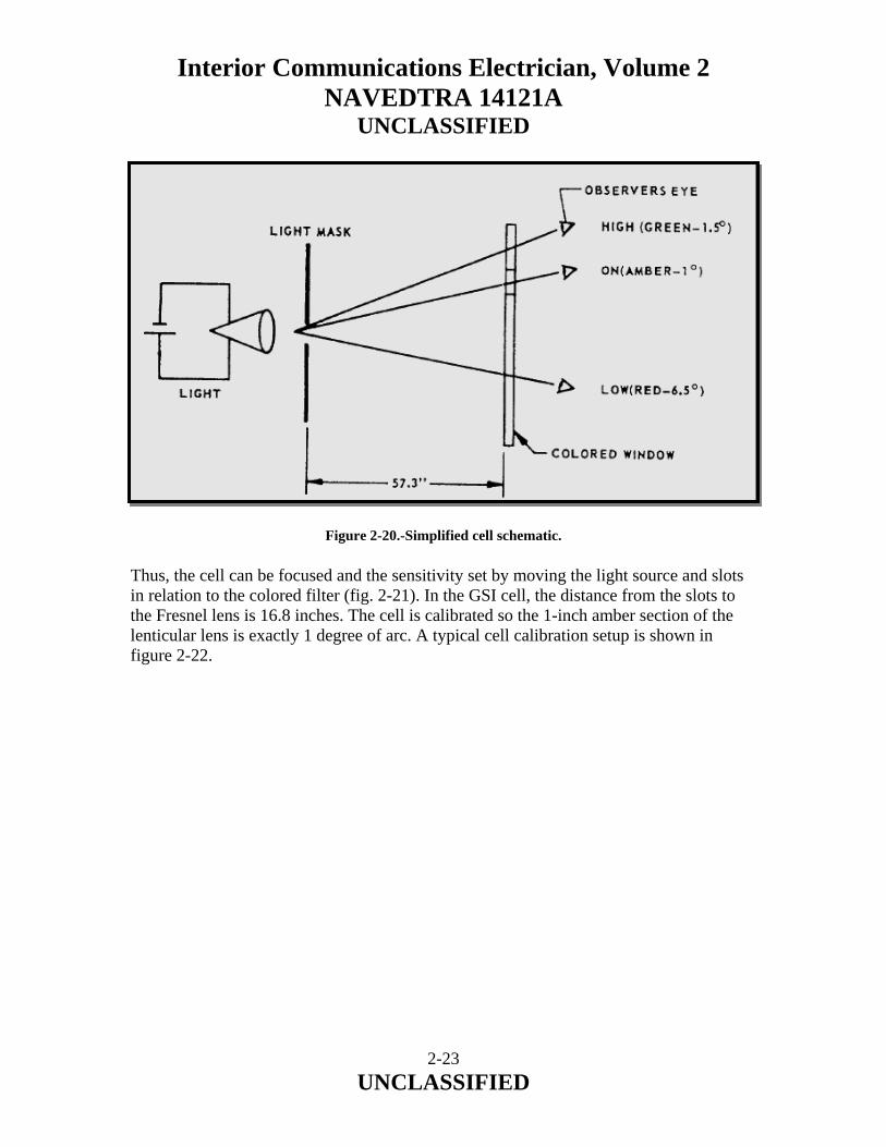
Interior Communications Electrician, Volume 2 NAVEDTRA 14121A
UNCLASSIFIED
Figure 2-20.-Simplified cell schematic. Thus, the cell can be focused and the sensitivity set by moving the light source and slots in relation to the colored filter (fig. 2-21). In the GSI cell, the distance from the slots to the Fresnel lens is 16.8 inches. The cell is calibrated so the 1-inch amber section of the lenticular lens is exactly 1 degree of arc. A typical cell calibration setup is shown in figure 2-22.
2-23 UNCLASSIFIED

Interior Communications Electrician, Volume 2 NAVEDTRA 14121A
UNCLASSIFIED
Figure 2-21.-Glide slope indicator, simplified functional diagram. To focus the cell, it must be placed on a level plate and two screens 10 feet (±1/8 inch) apart must be set up in front of the cell (see fig. 3-18). Turn the cell on and measure the height of the amber at screen one and subtract it from the height of the amber at screen two (fig. 2-22). If the cell is properly focused, the difference should be 2-3/32inch±1/8 inch. A dark band will appear between each of the colors due to light scattering at the interface; this band should be split evenly to obtain height measurements.
Figure 2-22.-Typical cell calibration setup (overhead view).
2-24 UNCLASSIFIED

Interior Communications Electrician, Volume 2 NAVEDTRA 14121A
UNCLASSIFIED
Figure 2-23.-Cell focusing measurements. Beam Angle The angle of the light beam to the horizon must be accurate and remain constant so a pilot may maintain a fixed rate to the ship. The glide slope angle is set using the degree plate on the right side of the cell and is checked on-the platform by means of pole checks to ensure the proper settings. At the same time the cell is focused it can be calibrated for proper glide slope. Referring to figure 2-23, you can see that the same screen arrangement can be used for measuring the angle of the red/amber inter- face. Set the baroscope supplied with the system on top of the level plate and mark off a reference mark on each screen. Adjust the cell glide angle using the knurled knob under the lamp housing until the difference between the reference mark on the red/amber interface on screen two is equal to 6-9/32 inches ±7/32 inch. Drill and pin the degree plate so it indicates three degrees. In this measurement, the cell should project the beam on the two screens and the center of the dark band between the red and amber filter should be used for all measurements. The slot through which the light bar is formed determines the size of the light bar as it is viewed through the cell face. In this system, it is not adjustable.
2-25 UNCLASSIFIED
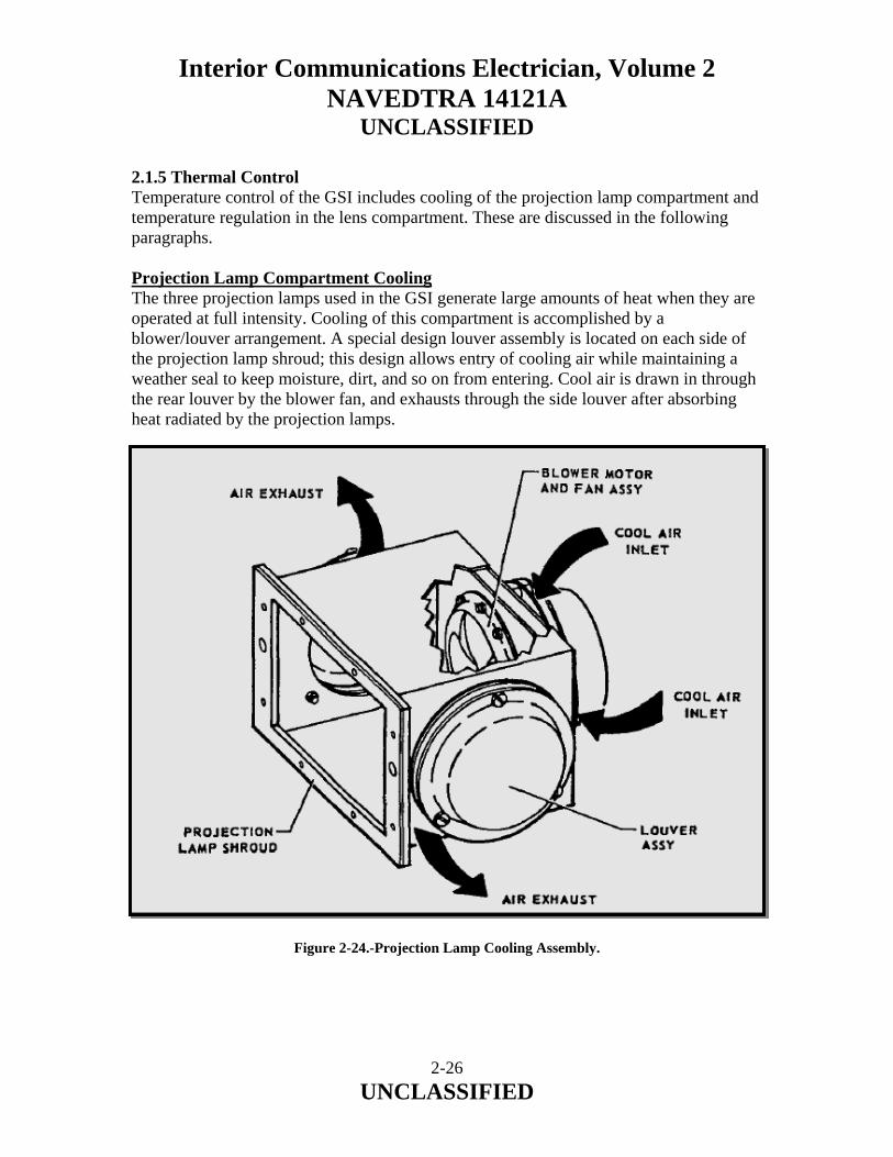
Interior Communications Electrician, Volume 2 NAVEDTRA 14121A
UNCLASSIFIED
2.1.5 Thermal Control Temperature control of the GSI includes cooling of the projection lamp compartment and temperature regulation in the lens compartment. These are discussed in the following paragraphs. Projection Lamp Compartment Cooling The three projection lamps used in the GSI generate large amounts of heat when they are operated at full intensity. Cooling of this compartment is accomplished by a blower/louver arrangement. A special design louver assembly is located on each side of the projection lamp shroud; this design allows entry of cooling air while maintaining a weather seal to keep moisture, dirt, and so on from entering. Cool air is drawn in through the rear louver by the blower fan, and exhausts through the side louver after absorbing heat radiated by the projection lamps. Figure 2-24.-Projection Lamp Cooling Assembly.
2-26 UNCLASSIFIED
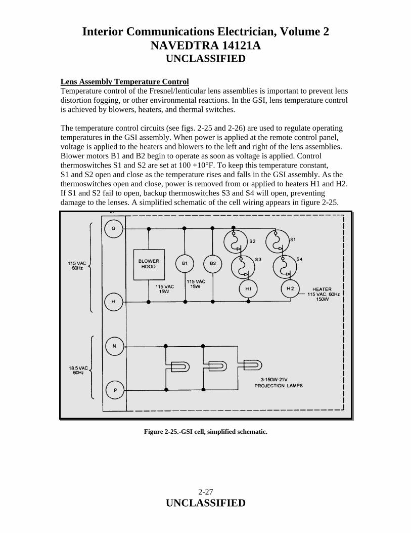
Interior Communications Electrician, Volume 2 NAVEDTRA 14121A
UNCLASSIFIED
Lens Assembly Temperature Control Temperature control of the Fresnel/lenticular lens assemblies is important to prevent lens distortion fogging, or other environmental reactions. In the GSI, lens temperature control is achieved by blowers, heaters, and thermal switches. The temperature control circuits (see figs. 2-25 and 2-26) are used to regulate operating temperatures in the GSI assembly. When power is applied at the remote control panel, voltage is applied to the heaters and blowers to the left and right of the lens assemblies. Blower motors B1 and B2 begin to operate as soon as voltage is applied. Control thermoswitches S1 and S2 are set at 100 +10°F. To keep this temperature constant, S1 and S2 open and close as the temperature rises and falls in the GSI assembly. As the thermoswitches open and close, power is removed from or applied to heaters H1 and H2. If S1 and S2 fail to open, backup thermoswitches S3 and S4 will open, preventing damage to the lenses. A simplified schematic of the cell wiring appears in figure 2-25.
Figure 2-25.-GSI cell, simplified schematic.
2-27 UNCLASSIFIED

Interior Communications Electrician, Volume 2 NAVEDTRA 14121A
UNCLASSIFIED
Figure 2-26.-Cell power. GSI Transformer The GSI uses three 21-volt 150-watt projection lamps for its light source. This is about 21 amps of current and would cause considerable voltage drop if long cables were used, thus the transformer assembly is mounted close to the GSI light and uses a fixed length of cable (10 feet) from the transformer secondary to the GSI cell connector. The system autotransformer supplying the primary voltage to the transformer is located in the remote control panel. A simplified schematic is shown in figure 2-26. 2.1.6 Stabilized Platform System The stabilized platform system is an electrohydraulic served platform used to stabilize the GSI against the ship’s pitch and roll. This keeps the tricolored GSI light at a fixed angle to the horizon. The stabilization is termed a one-to-one stabilization system. This means that for each degree of pitch or roll of the ship, the platform pitches or rolls an equal amount in the opposite direction. Thus, the platform remains level to the horizon or more precisely perpendicular to the local earth gravity vector. Operational Modes The system has four operational modes: Internal Gyro, Ship’s Gyro, Internal Gyro Stabilization Lock, and Ship’s Gyro Stabilization Lock.
2-28 UNCLASSIFIED

Interior Communications Electrician, Volume 2 NAVEDTRA 14121A
UNCLASSIFIED
2.1.7 SGSI System Normal Operating Procedure Stabilization from the internal gyro is the normal mode of system stabilization and is preferred to ship gyro mode because of higher system accuracy and addition of the gyro failure alarm. The system should always be operated in this mode as opposed to ship gyro operation unless a system failure prevents it. Operating control is normally conducted from the remote control panel from which the operator can turn the system on and vary the intensity of the source light. The system may also be turned on at the electronics enclosure assembly when the POWER ON/OFF push button is depressed. Adjustment of the source light intensity, however, can only be adjusted at the remote control panel. The normal mode is the interred gyro mode, where the gyro acts as the system sensor detecting any deviations from platform level. In this mode the platform will always remain level and cannot be offset. Internal Gyro Stabilization Lock Mode The internal gyro stab-leek mode disconnects internal gyro signals from the stabilization loop and locks the platform in a neutral position for test, alignment, and troubleshooting purposes. The system must be set to internal gyro for internal stab-leek operation. While in this mode, the test switches and manual drive potentiometer can be operated to enable insertion of signals independent of the local gyro. This mode enables the operator to isolate and test various parts of the system while disabling other parts. Ship Gyro Stabilization Mode Ship gyro stabilization is provided as an alternative to platform-mounted internal gyro stabilization. The system should be operated in the internal gyro mode unless component failure disables that portion of the circuitry since switching to the ship’s gyro reduces system accuracy. The internal gyro/ship gyro switch-indicator is on the component panel assembly. A ship gyro indicator on the remote control panel serves to remind system operators when the alternative stabilization source is in use. Ship Gyro Stabilization Lock Mode The ship gyro stabilization leek mode disconnects the ship’s gyro signals at the input to the gyro signal card assembly and replaces them with ground reference or manual drive potentiometer signals. This permits check-out and troubleshooting of ship gyro stabilization and stabilization error detecting circuitry. The internal gyro/ship gyro switch-indicator on the component panel assembly should be placed in the ship gyro position to enable the stabilized platform to track manual drive signals. The lamp control relay extinguishes GSI source lamps while operating in this stab-leek mode.
2-29 UNCLASSIFIED
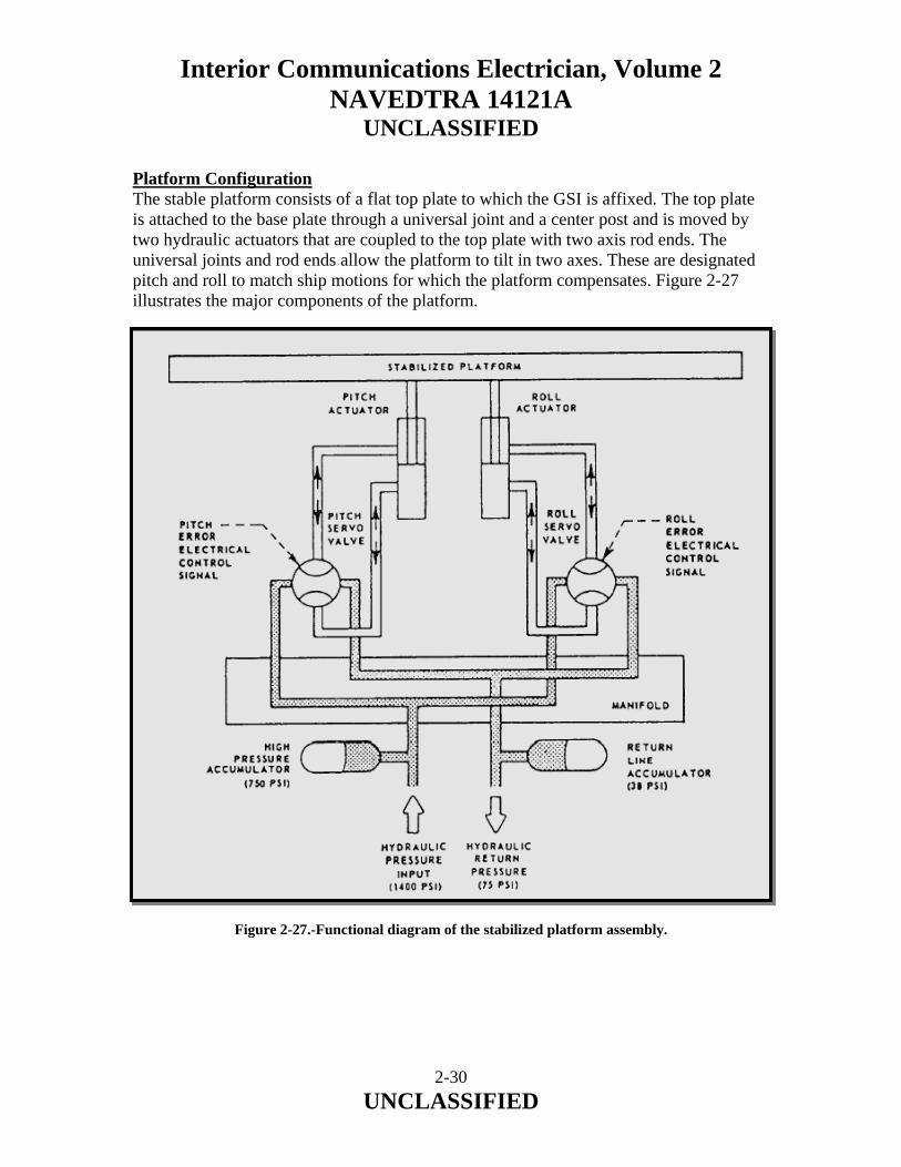
Interior Communications Electrician, Volume 2 NAVEDTRA 14121A
UNCLASSIFIED
Platform Configuration The stable platform consists of a flat top plate to which the GSI is affixed. The top plate is attached to the base plate through a universal joint and a center post and is moved by two hydraulic actuators that are coupled to the top plate with two axis rod ends. The universal joints and rod ends allow the platform to tilt in two axes. These are designated pitch and roll to match ship motions for which the platform compensates. Figure 2-27 illustrates the major components of the platform.
Figure 2-27.-Functional diagram of the stabilized platform assembly.
2-30 UNCLASSIFIED

Interior Communications Electrician, Volume 2 NAVEDTRA 14121A
UNCLASSIFIED
2.1.8 Servo Loops To understand the system operation, you need to have an understanding of feedback control systems. A feedback control system is a system where an input signal is compared with the system output and an error signal is generated. This error signal is then amplified and used to drive the output in a direction to reduce the error. Assuming the input and output pots are initially equal, then the difference in voltage is zero and there is no error. If the input command pot is moved, then an error is generated. The amplifier amplifies the error and drives the power actuator that moves the output pot in a direction to reduce the error. Thus, in a feedback system, the output can be made to follow the input. This type of feedback system is often referred to as a servo loop. The GSI stable platform uses two servo loops in each axis, the gyro loop and the LVDT loop. In the gyro loop, the gyro is used as an error detector sensing the downward pull of gravity at its particular location. This is termed earth’s local gravity vector. The gyro lines itself up with this downward pull and any difference between the gyro case and its internal reference provides an output. This output is used as an error signal to correct the platform top to earth level. The LVDT loop is quite similar to the gyro feedback loop, only the sensor is changed. Figure 2-28 shows that the LVDT is mechanically connected to the actuator to sense its position pot. The feedback signal from the LVDT is connected to the error detector. The LVDT has as its input either zero (stab-lock) or a signal from the manual position pot. With the manual position pot switched out of the circuit, the input to the error detector is zero (ground). The LVDT is adjusted so its output is zero when the platform top is level to its base, thus errors are only generated when the LVDT has an output and these are amplified and drive the output to zero. In operation, any voltages measured in the servo loops are small and are proportional to the system error. The complete system servo feedback loop (single channel) is shown in figure 2-29. This incorporates both the gyro and stab-lock loops and the switching between them.
2-31 UNCLASSIFIED
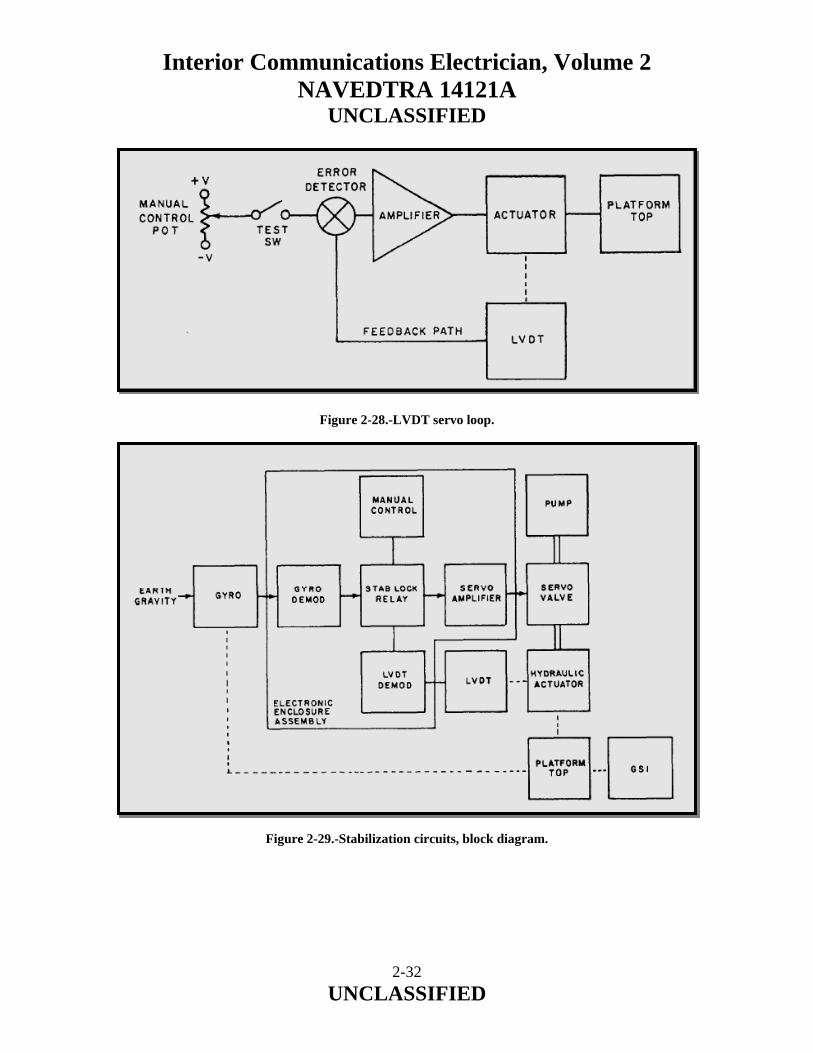
Interior Communications Electrician, Volume 2 NAVEDTRA 14121A
UNCLASSIFIED
Figure 2-28.-LVDT servo loop. Figure 2-29.-Stabilization circuits, block diagram.
2-32 UNCLASSIFIED
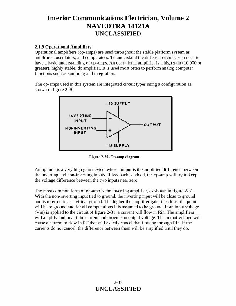
Interior Communications Electrician, Volume 2 NAVEDTRA 14121A
UNCLASSIFIED
2.1.9 Operational Amplifiers Operational amplifiers (op-amps) are used throughout the stable platform system as amplifiers, oscillators, and comparators. To understand the different circuits, you need to have a basic understanding of op-amps. An operational amplifier is a high gain (10,000 or greater), highly stable, dc amplifier. It is used most often to perform analog computer functions such as summing and integration. The op-amps used in this system are integrated circuit types using a configuration as shown in figure 2-30.
Figure 2-30.-Op-amp diagram. An op-amp is a very high gain device, whose output is the amplified difference between the inverting and non-inverting inputs. If feedback is added, the op-amp will try to keep the voltage difference between the two inputs near zero. The most common form of op-amp is the inverting amplifier, as shown in figure 2-31. With the non-inverting input tied to ground, the inverting input will be close to ground and is referred to as a virtual ground. The higher the amplifier gain, the closer the point will be to ground and for all computations it is assumed to be ground. If an input voltage (Vin) is applied to the circuit of figure 2-31, a current will flow in Rin. The amplifiers will amplify and invert the current and provide an output voltage. The output voltage will cause a current to flow in RF that will exactly cancel that flowing through Rin. If the currents do not cancel, the difference between them will be amplified until they do.
2-33 UNCLASSIFIED
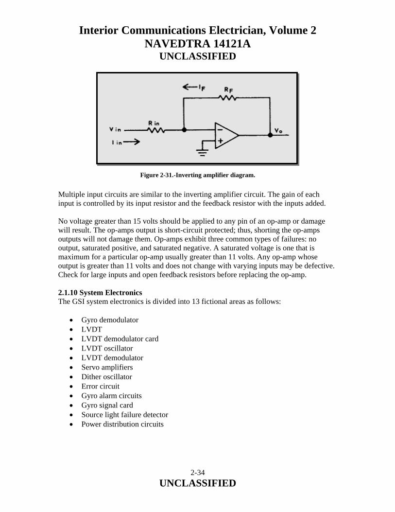
Interior Communications Electrician, Volume 2 NAVEDTRA 14121A
UNCLASSIFIED
Figure 2-31.-Inverting amplifier diagram. Multiple input circuits are similar to the inverting amplifier circuit. The gain of each input is controlled by its input resistor and the feedback resistor with the inputs added. No voltage greater than 15 volts should be applied to any pin of an op-amp or damage will result. The op-amps output is short-circuit protected; thus, shorting the op-amps outputs will not damage them. Op-amps exhibit three common types of failures: no output, saturated positive, and saturated negative. A saturated voltage is one that is maximum for a particular op-amp usually greater than 11 volts. Any op-amp whose output is greater than 11 volts and does not change with varying inputs may be defective. Check for large inputs and open feedback resistors before replacing the op-amp. 2.1.10 System Electronics The GSI system electronics is divided into 13 fictional areas as follows:
• Gyro demodulator • LVDT • LVDT demodulator card • LVDT oscillator • LVDT demodulator • Servo amplifiers • Dither oscillator • Error circuit • Gyro alarm circuits • Gyro signal card • Source light failure detector • Power distribution circuits
2-34 UNCLASSIFIED
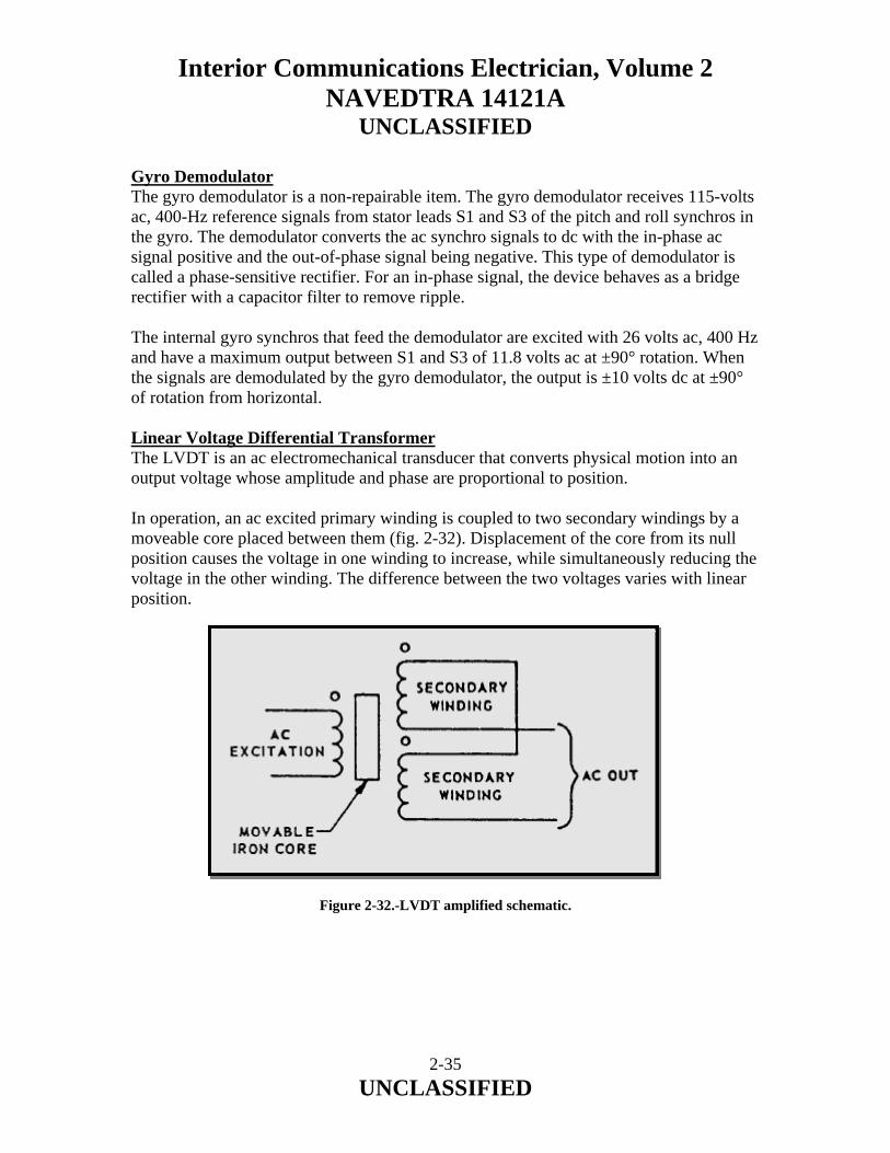
Interior Communications Electrician, Volume 2 NAVEDTRA 14121A
UNCLASSIFIED
Gyro Demodulator The gyro demodulator is a non-repairable item. The gyro demodulator receives 115-volts ac, 400-Hz reference signals from stator leads S1 and S3 of the pitch and roll synchros in the gyro. The demodulator converts the ac synchro signals to dc with the in-phase ac signal positive and the out-of-phase signal being negative. This type of demodulator is called a phase-sensitive rectifier. For an in-phase signal, the device behaves as a bridge rectifier with a capacitor filter to remove ripple. The internal gyro synchros that feed the demodulator are excited with 26 volts ac, 400 Hz and have a maximum output between S1 and S3 of 11.8 volts ac at ±90° rotation. When the signals are demodulated by the gyro demodulator, the output is ±10 volts dc at ±90° of rotation from horizontal. Linear Voltage Differential Transformer The LVDT is an ac electromechanical transducer that converts physical motion into an output voltage whose amplitude and phase are proportional to position. In operation, an ac excited primary winding is coupled to two secondary windings by a moveable core placed between them (fig. 2-32). Displacement of the core from its null position causes the voltage in one winding to increase, while simultaneously reducing the voltage in the other winding. The difference between the two voltages varies with linear position. Figure 2-32.-LVDT amplified schematic.
2-35 UNCLASSIFIED

Interior Communications Electrician, Volume 2 NAVEDTRA 14121A
UNCLASSIFIED
LVDT Demodulator Card The LVDT demodulator card supplies a constant voltage ac excitation to the LVDT primaries and converts the pitch and roll LVDT amplitude and phase signals to a variable dc voltage. This is accomplished in three separate circuits: the LVDT oscillator and the pitch and roll demodulators. LVDT Oscillator The LVDT oscillator consists of a quadrature oscillator and a power amplifier. The quadrature oscillator is used to generate a constant-amplitude, constant frequency sine wave. The power amplifier is a low output-impedance driver used to power the LVDT primaries and the pitch and roll demodulator diode switches. To understand the operation of the quadrature oscillator, assume capacitor C3 of figure 2-33 is initially charged positive. The non-inverting integrator IC3-1 will charge C1 so its output goes positive. This positive voltage will cause the inverting integrator IC3-2 to charge its capacitor C2 and its output will go negative. This negative voltage will discharge C3. This will continue until C3 is charged negative and then reverse, causing the circuit to oscillate. The zener diodes clamp the output and stabilize the amplitude so the output voltage is a stable 6.5 volts ac.
Figure 2-33.-LVDT quadrature oscillator.
2-36 UNCLASSIFIED

Interior Communications Electrician, Volume 2 NAVEDTRA 14121A
UNCLASSIFIED
LVDT Demodulator The pitch and roll LVDT demodulator are identical except for their gains. They are called phase sensitive demodulators. The input to the demodulator is a variable-voltage, variable-phase signal from the LVDT. This signal is full-wave rectified and filtered and its output polarity is positive for signals out of phase with the reference and negative for signals in phase. Servo Amplifiers The pitch and roll servo amplifier circuit cards are identical except for the gains and servo compensation. Three inputs are summed into amplifier A1: LVDT, gyro/manual control, and rate gyro. In normal operation, only gyro signals are used. In stab-lock mode, the LVDT signal is the input with manual control being used for testing. Figure 2-34 shows a schematic diagram of the pitch servo amplifier card.
2-37 UNCLASSIFIED
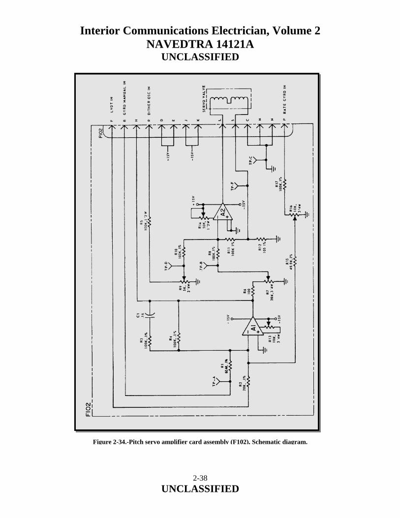
Interior Communications Electrician, Volume 2 NAVEDTRA 14121A
UNCLASSIFIED
Figure 2-34.-Pitch servo amplifier card assembly (F102), Schematic diagram.
2-38 UNCLASSIFIED

Interior Communications Electrician, Volume 2 NAVEDTRA 14121A
UNCLASSIFIED
Dither Oscillator The dither oscillator provides a high-frequency (compared to system response) signal to the servo valves to keep them in constant motion to prevent sticking at null. The dither oscillator is a phase shift oscillator. It depends on the phase shifts inherent in RC networks to shift the phase of the amplifier feedback 180°. This will cause a sustained oscillation if the amplifier gain is high enough. The gain also determines the quality of the sine wave. Error Circuit Card The error circuit card is used to monitor the pitch and roll servo errors. It allows monitoring of the gyro’s internal pendulum reference for test purposes. Since the system is not perfect, servo errors are present. Voltages representing system errors are compared with a reference voltage that represents the maximum allowed system error. If it is exceeded the system will go from ready to not ready and turn out the GSI light. System errors existing during turn-on would trigger a false not ready light. To prevent this, a delay is included in the error circuit. A schematic of the error circuit is shown in figure 2-35.
2-39 UNCLASSIFIED

Interior Communications Electrician, Volume 2 NAVEDTRA 14121A
UNCLASSIFIED
2-40 UNCLASSIFIED
Figure 2-35.-Error Circuit Schematic Diagram.
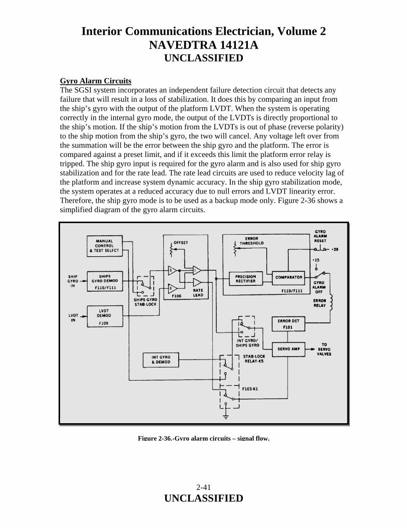
Interior Communications Electrician, Volume 2 NAVEDTRA 14121A
UNCLASSIFIED
Gyro Alarm Circuits The SGSI system incorporates an independent failure detection circuit that detects any failure that will result in a loss of stabilization. It does this by comparing an input from the ship’s gyro with the output of the platform LVDT. When the system is operating correctly in the internal gyro mode, the output of the LVDTs is directly proportional to the ship’s motion. If the ship’s motion from the LVDTs is out of phase (reverse polarity) to the ship motion from the ship’s gyro, the two will cancel. Any voltage left over from the summation will be the error between the ship gyro and the platform. The error is compared against a preset limit, and if it exceeds this limit the platform error relay is tripped. The ship gyro input is required for the gyro alarm and is also used for ship gyro stabilization and for the rate lead. The rate lead circuits are used to reduce velocity lag of the platform and increase system dynamic accuracy. In the ship gyro stabilization mode, the system operates at a reduced accuracy due to null errors and LVDT linearity error. Therefore, the ship gyro mode is to be used as a backup mode only. Figure 2-36 shows a simplified diagram of the gyro alarm circuits.
Figure 2-36.-Gyro alarm circuits – signal flow.
2-41 UNCLASSIFIED

Interior Communications Electrician, Volume 2 NAVEDTRA 14121A
UNCLASSIFIED
The gyro alarm failure alarm circuit can be disabled by pushing the gyro alarm OFF push button. This supplies +15 volts dc to one side of the error relay and effectively disconnects the gyro failure alarm circuits. In addition an interlock circuit prevents unwanted platform oscillation when the alarm circuit is not actuated. Gyro Demodulator Board The gyro demodulator board contains a synchro to dc converter and a gyro error detector circuit. The F110 and F111 are identical cards: one is used in the pitch channel and the other in roll. The synchro to dc converter is a sealed module not repairable by shipboard personnel. Gyro Error Detector Circuit The gyro error detector circuit consists of a precision full wave rectifier, a filter, a voltage comparator, a transistor, and a relay. The input signal to this card is the summation of the ship’s gyro and the platform LVDTs. Gyro Signal Card Assembly The gyro signal card (F106) amplifies and sums the demodulated pitch and roll synchro signals from the ship’s gyro with the platform LVDT outputs. It also provides offset adjustments to make up for any difference in alignment between the ship’s gyro and platform. In addition, rate lead signals are derived by differentiating the ship gyro signals. Source Light Failure Detector The source light failure detector is a circuit that monitors the voltage and current going to the three source lights. When one or more of the source lamps fail, the source light failure indicator on the remote panel is illuminated. Power Distribution Circuits The system requires two power sources from the ship 440-volts ac, 60-Hz, 2.7-amp power for the pump and 115-volts ac, 60-HZ, 15-amp power for the rest of the system. In standby (system circuit breaker on), the system heaters and standby lights are on. When the POWER ON push buttons are depressed, the internal power supplies are energized except for the ±15 volts dc. The ±15 volts dc supply is energized after the time delay relay has timed out, the hydraulic pump is running, and system hydraulic pressure is normal. Then, the hydraulic pressure switch is actuated.
2-42 UNCLASSIFIED

Interior Communications Electrician, Volume 2 NAVEDTRA 14121A
UNCLASSIFIED
2.1.11 Hydraulic Components The SGSI system uses hydraulic pressure for motive power. A constant-pressure, variable-delivery hydraulic pump supplies hydraulic pressure. Pressure fluctuations are dampened by accumulators. The fluid is gaited by servo valves into either side of the hydraulic cylinders. The fluid pressure then causes the cylinders to move the platform. The hydraulic system is sensitive to dirt and other contaminants. Therefore, care must be used when adding fluid or opening any part of the hydraulic system. Refer to the hydraulic pump assembly shown in figure 2-9 when studying the following paragraphs. Hydraulic Accumulator The hydraulic accumulators used in this system are steel cylinders with internal rubber bladders. Before putting the accumulators in service, the bladders are pressurized with dry nitrogen to 700 psig for the high--pressure accumulator and 38 psig for the low-pressure accumulator. When hydraulic pressure is applied, the accumulator fills with fluid and the bladder is compressed until the dry nitrogen charge pressure equals that of the hydraulic system. In this system, it is 1400 psig. Because of the bladder compression, the accumulator will absorb pressure fluctuations and prevent hydraulic hammer. If the system momentarily requires a higher flow than the pump will supply, the accumulator will provide it and be recharged when the demand has passed. Hydraulic Cylinder The hydraulic cylinders used in this system are linear actuators. Hydraulic fluid gated by the servo valve will push the piston in either direction. The hydraulic pressure exerted by the piston is 1400 psig in extension and 700 psig in compression. Extreme care must be exercised when working on the system due to the amount of force available. The cylinder is an inherently reliable device requiring little maintenance in normal use. However, the only required maintenance is cleaning dirt and grit off the actuator rod and tightening the packing gland nut if a leak develops. Do not over tighten the gland nut or the packing will bind on the rod, causing the cylinder to chatter in operation. If cylinder replacement becomes necessary, the defective cylinder must be returned through supply charnels for overhaul. System low-amplitude vibration, or chatter in some cases, may be traceable to cylinder internal binding; in which case the cylinder should be replaced.
2-43 UNCLASSIFIED

Interior Communications Electrician, Volume 2 NAVEDTRA 14121A
UNCLASSIFIED
Servo Valve Servo valves are commonly used in closed-loop servo systems. They control the flow of fluid to or from the load actuator in proportion to the impact current signal to the valves’ torque motor. Hydraulic Pump The hydraulic pump used in this system is a constant-pressure, variable-delivery pump. It is similar to a constant voltage source in which current will vary upon demand. Referring to figure 2-9, hydraulic fluid is gravity fed from the reservoir to the pump unit through the pump case fill piping to ensure that the pump case is full at all times, thus keeping air out of the line. The motor-driven pump draws fluid through a suction strainer, located in the reservoir, into the pump where it is pressurized to 1400 psi and applied to the hydraulic pressure line. A fluid flow filter removes solid impurities greater than 3 microns in size. In the event the filter becomes clogged, it is bypassed. The filter output then flows past the pressure gauge, the pressure switch, and the bypass valve. The pressure gauge should indicate 1400 psi in normal operation, and the pressure switch should be closed for pressures above 1200 psi. The bypass valve is normally closed and will open only if the pressure exceeds 1800 psi. If the pump is operating normally, the bypass valve will be closed and the fluid will flow through the check valve and out the gate valve to the system. The check valve is a one-way valve. The fluid returning from the system flows through the return gate valve and check valve into the reservoir. The return check valve only allows fluid to flow in one direction and requires 75 psi of pressure before it will open. This maintains the return line pressure at 75 psi. For the pump, heater, and overtemperature switch to operate properly, the fluid reservoir must be properly filled. Too little fluid may actually cause the pump to overheat. Pump Motor Contactor The motor controller usually has 440 volts ac applied to it. The pump is actuated by applying 115 volts ac to the motor controller relay. The pump motor is protected by thermal overloads, located in the motor controller. A thermal overload is a relay that is actuated by heat. Motor current flows through a low-value resistor, generating a small amount of heat. If the current increases beyond a specified value (3.7 amps), the heat generated will melt a solder bond on a ratchet wheel, which holds back a spring-loaded relay. This will cut the pump power by opening the circuit to the motor control relay. The thermal relay should then be allowed to cool before pushing the reset button on the pump controller.
2-44 UNCLASSIFIED

Interior Communications Electrician, Volume 2 NAVEDTRA 14121A
UNCLASSIFIED
The pump motor is factory wired for 440-volts ac operation and should not be changed as the motor controller current limits are set for 440-volts ac operation. Hydraulic Fluid Heater The fluid heater is a 175-watt immersion-type heater. The fluid must be kept at approximately 70°F or greater to prevent it from becoming too viscous and causing servo errors. The heater is a Calrod type with a built-in thermostat. The thermostat is normally factory set but may be adjusted if necessary. To adjust the heater, unscrew the cover plate by turning counterclockwise and use the internal screwdriver adjustment to set the temperature. It will take about a half hour for the temperature to stabilize. Overtemperature Switch The overtemperature switch is a mechanically adjustable immersion-type thermoswitch. It is used to indicate overheating of the pump oil. It does not indicate a direct failure. In a warm environment of approximately 85°F the oil temperature will be about 120°F. An increase in oil temperature will most likely be due to increased fluid viscosity or a clogged pump filter. If this is the case, the pump should be drained and flushed with warm water, and the fluid and filter replaced. Hydraulic Pressure Switch The hydraulic pressure switch is a single-pole, double- throw, pressure-actuated switch. It is used to turn on the system electronics when there is enough pressure to stabilize the system. It is normally set to actuate at 1200 psi. The pressure switch is adjusted by turning the label until the inner body is exposed. It can be turned with a screwdriver or other instrument inserted in the inner body holes. The pressure switch setting is decreased by turning the inner body counterclockwise as viewed from the connector end. The hydraulic pressure switch is a non-repairable item that must be replaced if it is not operating properly. 2.2.0 HORIZON REFERENCE SET (HRS) The Horizon Reference Set (HRS) is normally maintained by the Ship’s Electrician Mates. This brief discussion is provided due to the HRS’s interface with various IC systems.
2-45 UNCLASSIFIED

Interior Communications Electrician, Volume 2 NAVEDTRA 14121A
UNCLASSIFIED
2.2.1 Helicopter/Ship Interface Air capable ships usually include a flight deck and hangar enclosure at the aft end. The flight deck accommodates helicopters but with minimum all-round clearance. When the helicopter is hovering above the flight deck prior to landing, the helicopter pilot might experience considerable judgment difficulties. These are due to the rolling and pitching motions of the ship. Therefore, these flight deck facilities are frequently expanded to include a Horizon Reference Set (HRS) and a Recovery Assist, Secure and Traverse (RAST) System. The HRS is incorporated in the hangar and flight deck locations of air-capable ships. The HRS consists of three separate units, shown in Figure 2-37. They function together to provide a stable, external, visual, horizon reference as a pilot aid during helicopter deck landings. The reference is in the form of a horizontal bar assembly fitted with electroluminescent panels along its full length. The HRS is of significant importance to level flight: especially during inclement weather; at night when the true horizon is obscured; and whenever the flight deck is rolling. The other component associated with flight deck landings is the RAST system. The RAST system is incorporated in the flight deck of helicopter-equipped ships. The recovery assist portion of the system enables the ship's helicopter to land safely on the flight deck particularly during adverse weather conditions. It also secures the helicopter after landing. This prevents equipment damage during extreme movements of the ship. Shipboard helicopters are modified to utilize the shipboard RAST system. Helicopter modifications include a main probe and messenger winch, a retractable tail probe, and associated pilot controls. When the helicopter lands, it is imperative that the recovery takes place at the same location every time. During the ship's forward motion and particularly during adverse weather conditions, when the ship is subjected to violent rolling and pitching motions, the RAST system assists in aligning the helicopter during descent. During the final approach to landing and when the helicopter is tethered to the ship while hovering, level flight must be maintained. The horizon reference is located on the hangar structure. There it can be observed during the pilot's visual structure clearance scan. The HRS requires two sources of ship's power to energize it. These supplies are connected to the Electronic Components Assembly (ECA).
2-46 UNCLASSIFIED

Interior Communications Electrician, Volume 2 NAVEDTRA 14121A
UNCLASSIFIED
The roll angle of the lamp panel and bar assembly (LPBA) is derived from a synchro signal. This signal is obtained from the ship's vertical gyro reference system. The input signal is connected to the ECA. Figure 2-37.-Horizon Reference Set.
2-47 UNCLASSIFIED

Interior Communications Electrician, Volume 2 NAVEDTRA 14121A
UNCLASSIFIED
2.2.2 Safety Features The HRS is equipped with an automatic fault detection .system which:
a. lights a red warning lamp if the horizon reference is faulty; b. moves the LPBA to the 00 roll position, if possible, if a fault occurs; c. shuts down the system.
The HRS shuts down in anyone of three modes. These modes depend upon either the type of fault condition or if the shut-down is initiated by the operator. The specific shut-down modes are: Soft. This mode results in the LPBA returning to the 00 roll position, if possible, before being locked by the brake. The electroluminescent lamps on the LPBA are turned off immediately. The warning lamp is lit immediately. This mode occurs if there is > 20 difference between the true horizon and the LPBA reference. The> 20 difference must have been sustained for 2 seconds and within the normal operating roll angle limits of the LPBA. Hard. This mode results in the LPBA being locked by the brake in its present position. The electroluminescent lamps are turned off immediately. This mode occurs if there is a partial or complete failure of the external 400 Hz power, internal DC power supplies or input gyro reference signal. For these failures, the warning lamp lights immediately. A hard shut-down can also be initiated by the operator. This is accomplished by pressing the RESET push-button on the active control station. In this case, the warning lamp does not light. Normal. This mode results in the LPBA returning to the 00 roll position before being locked by the brake. The electroluminescent lamps are turned off immediately. The warning lamp does not light. This mode is initiated by the operator when the STOP pushbutton is pressed on the active control station. 2.2.3 Equipment Description The HRS comprises three separate units interconnected electrically:
a. Indicator, Stabilization Data (ISO). b. Control-Indicator (CI). c. Electronic Components Assembly (ECA).
2-48 UNCLASSIFIED

Interior Communications Electrician, Volume 2 NAVEDTRA 14121A
UNCLASSIFIED
2.2.4 Indicator, Stabilization Data (ISD) The ISO comprises three sub-units: the housing, the LPBA and the warning lamp. They are located centrally on top of the hangar structure at its aft end. Housing. This unit contains the electromechanical drive. The drive positions the LPBA so that it remains parallel to the natural horizon. The electrical control system rotates the LPBA in the direction which counteracts the roll of the ship to provide the true horizon reference. The unit includes monitoring sensors which measure the LPBA roll angle relative to the housing. The unit also includes electrical limit switches. These switches drive the LPBA back into its roll operating range if the electronic limits fail. Mechanical stops in the unit prevent the LPBA from hitting the ship's superstructure if the electrical limit switches fail. The unit also supports the warning lamp which indicates system failure. The housing is mounted on a pedestal. This allows clearance for the LPBA to travel through its complete operating arc (approximately ± 40° from the horizontal) without hitting the superstructure. Lamp Panel and Bar Assembly (LPBA). The gyro-stabilized LPBA which is 10ft long provides a visual horizon reference for the helicopter pilot. The bar provides a stable external horizon reference continuously to the pilot of the helicopter which is approaching and landing on the flight deck. This is desirable, particularly at night. The bar is illuminated throughout its length by green, electroluminescent panels. The illuminated bar is visible in the same plane of vision as seen by the helicopter pilot when conducting the normal obstruction clearance scan. Bar rotation is defined as cw or ccw when facing the electroluminescent panels. When the bar is parallel to the ship's deck, it is referred to as being in the 0° roll position. It should be noted that the horizon reference applies only to the lateral roll axis of the ship. The horizon bar provides a reference of the true horizon which is independent of the ship's rolling motion. The bar does not provide a reference for judgment of the ship's pitching motion or pitching of the helicopter. Furthermore, although the true horizon reference is provided continuously, the bar and housing are secured to the ship's structure. Therefore, they are not restrained from movement (i.e. displacement) in the ship's rolling plane. The pitching and displacement motion of the ship occurs at a much slower frequency than the roll. Therefore, these motions do not impact helicopter operation significantly.
2-49 UNCLASSIFIED

Interior Communications Electrician, Volume 2 NAVEDTRA 14121A
UNCLASSIFIED
Warning Lamp. The warning lamp is attached to the top of the housing. It consists of six incandescent lamps covered by a red lens. The warning lamp lights to warn the pilot of an approaching helicopter if there is a fault in the HRS. 2.2.5 Control-Indicator (CI) The CI contains HRS power and operating controls, and also status indicators. These controls and indicators are duplicated in the ECA however the CI has primary control with override capability. The CI is located in the vicinity of the helicopter control station. 2.2.6 Electronic Components Assembly (ECA) The ECA contains all the electronic servo control circuitry, primary power, signal and operating controls and adjustments. Its principal function is to provide electrical signals to drive the bar assembly to the correct roll position. The ECA is located typically in the flight control area. 2.3.0 WAVE-OFF LIGHT SYSTEM FOR AIR CAPABLE AND AMPHIBIOUS AVIATION SHIPS This section contains information describing each assembly of the Mk 1 Mod 0 Wave-off Light System (Figure 2-38). Information is also provided which will enable operating personnel to prepare and operate the Wave-off Light System. The information provided in this section is presented under the following topics:
1. Purpose of Wave-off Light System. 2. Physical description. 3. Operating instructions.
2.3.1 Purpose of Wave-Off Light System The Wave-off Light System is an electronic system designed for use on aviation facilities ships. Two wave-off lights are installed one on each side of the stabilized platform. These wave-off lights provide a visual indication, which when flashing, informs the helicopter pilot that he is to abort the landing attempt and initiate a new landing approach.
2-50 UNCLASSIFIED
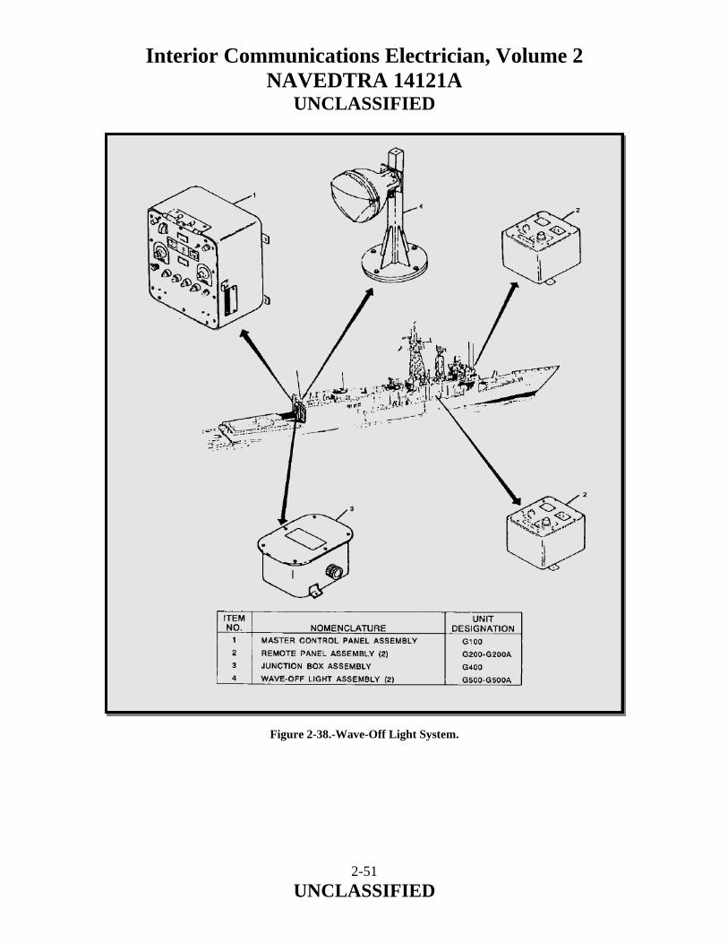
Interior Communications Electrician, Volume 2 NAVEDTRA 14121A
UNCLASSIFIED
Figure 2-38.-Wave-Off Light System.
2-51 UNCLASSIFIED

Interior Communications Electrician, Volume 2 NAVEDTRA 14121A
UNCLASSIFIED
2.3.2 Physical Description The assemblies that comprise the Wave-off Light System together with their unit numbers are as follows:
1. Master control panel assembly (GI00) 2. Remote panel assembly (G200, G200A) 3. Junction box assembly (G400) 4. Wave-off light assembly (G500, G500A)
2.3.3 Technical Characteristics The technical characteristics of the Wave-off Light System are listed in Table 2-1.
MODE CHARACTERISTIC Light Intensity Adjustable from a variable minimum brightness to
100%. Flash Rate Variable rate at 50% duty cycle. Preset at 90
flashes/min. Wave-Off Initiation Activated with flash indication from the master
control panel and remote panels. Wave-Off Monitor A “positive” indicator, sensing voltage to the lamps,
flashes when the wave-off lights are operable. Table 2-1.-Technical Characteristics. 2.3.4 Input Power Requirements The power required to operate the Wave-off Light System is supplied from the ship's emergency power supply. The amplitude and frequency of the 115-volt, 60Hz, 7.5ampere source (ungrounded) must be regulated to within 10 percent. 2.3.5 Master Control Panel (G100) The master control panel (Figure 2-39) is signal processing, distribution, and control center for the Wave-off Light System. The panel has a removable cover which protects the panel controls from moisture and dirt. Lowering the panel face plate provides access to the card cage assembly, which holds the monitor, flasher/driver and extender cards, the step-down transformer (115/55 vac), and the terminal boards used for system interconnecting wire terminations.
2-52 UNCLASSIFIED
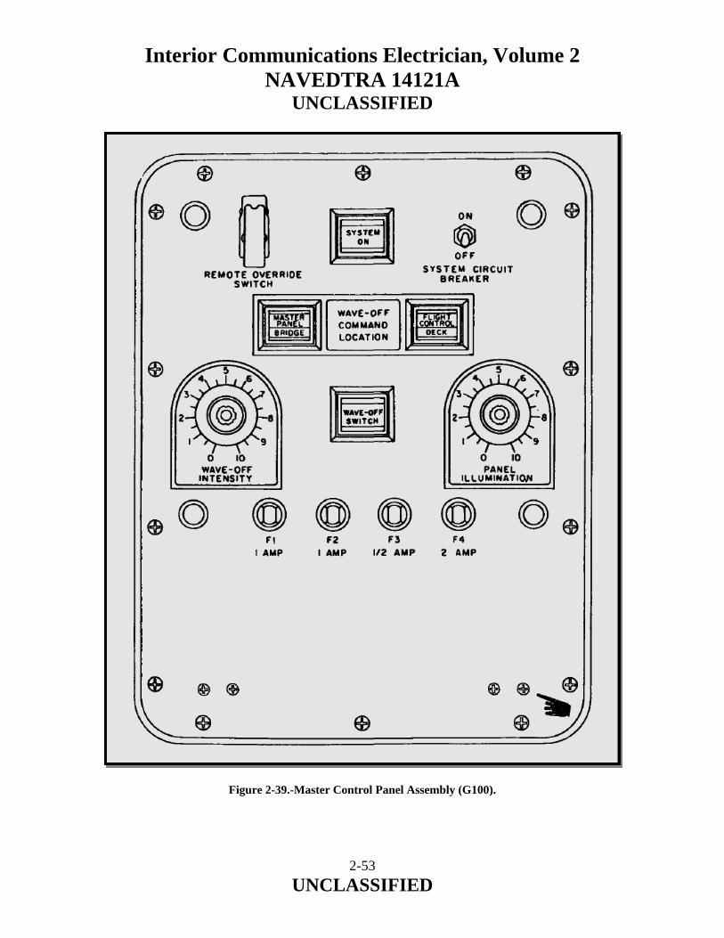
Interior Communications Electrician, Volume 2 NAVEDTRA 14121A
UNCLASSIFIED
Figure 2-39.-Master Control Panel Assembly (G100).
2-53 UNCLASSIFIED
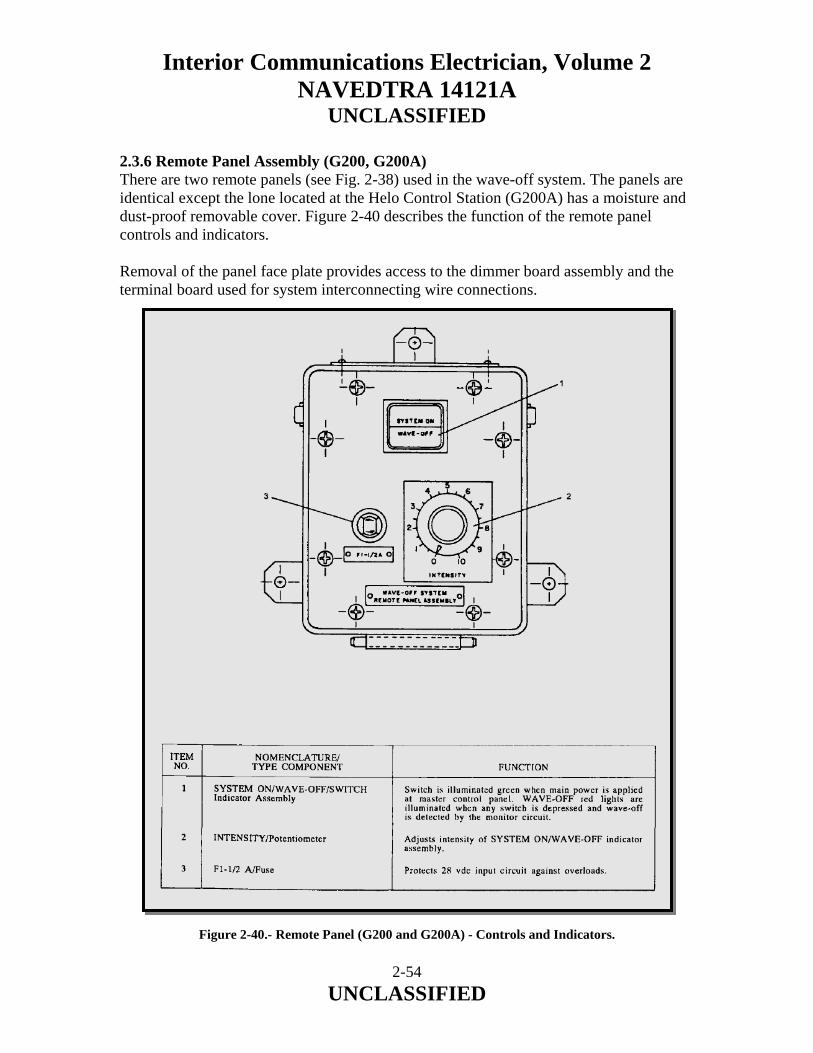
Interior Communications Electrician, Volume 2 NAVEDTRA 14121A
UNCLASSIFIED
2.3.6 Remote Panel Assembly (G200, G200A) There are two remote panels (see Fig. 2-38) used in the wave-off system. The panels are identical except the lone located at the Helo Control Station (G200A) has a moisture and dust-proof removable cover. Figure 2-40 describes the function of the remote panel controls and indicators. Removal of the panel face plate provides access to the dimmer board assembly and the terminal board used for system interconnecting wire connections.
Figure 2-40.- Remote Panel (G200 and G200A) - Controls and Indicators.
2-54 UNCLASSIFIED

Interior Communications Electrician, Volume 2 NAVEDTRA 14121A
UNCLASSIFIED
2.3.7 Junction Box Assembly (G400) The junction box assembly (see Fig. 2-38) is a moisture and dust-proof unit which provides a means to connect the cable from the master control panel with the wave-off light cables. It is located with the wave-off light assemblies. 2.3.8 Wave-Off Light Assembly (G500, G500A) The wave-off light assemblies (see Fig. 2-38) are identical units, which are installed one on each side of the stabilized platform. System interconnecting cabling connects to each light by way of a connector located at the rear of each lamp housing. This connector has a cover, attached with a retaining chain, which is used to prevent moisture and dirt from entering the connector when the interconnecting cable is not attached. 2.3.9 Operating Instructions Information is provided for operating the Wave-off Light System in normal and remote operational mode. This information is presented under the following topics:
1. System controls, indicators, and fuses. 2. Safety precautions. 3. System initial control settings. 4. System turn-on procedure. 5. System normal and remote operation modes. 6. System turnoff procedure.
2.3.10 System Controls, Indicators and Fuses The information necessary to familiarize personnel with the operating controls, indicators, and fuses is presented in Figures 2-41 and 2-40. The information provided in these figures and tables will enable personnel to locate, identify, and understand the function of each component listed.
2-55 UNCLASSIFIED
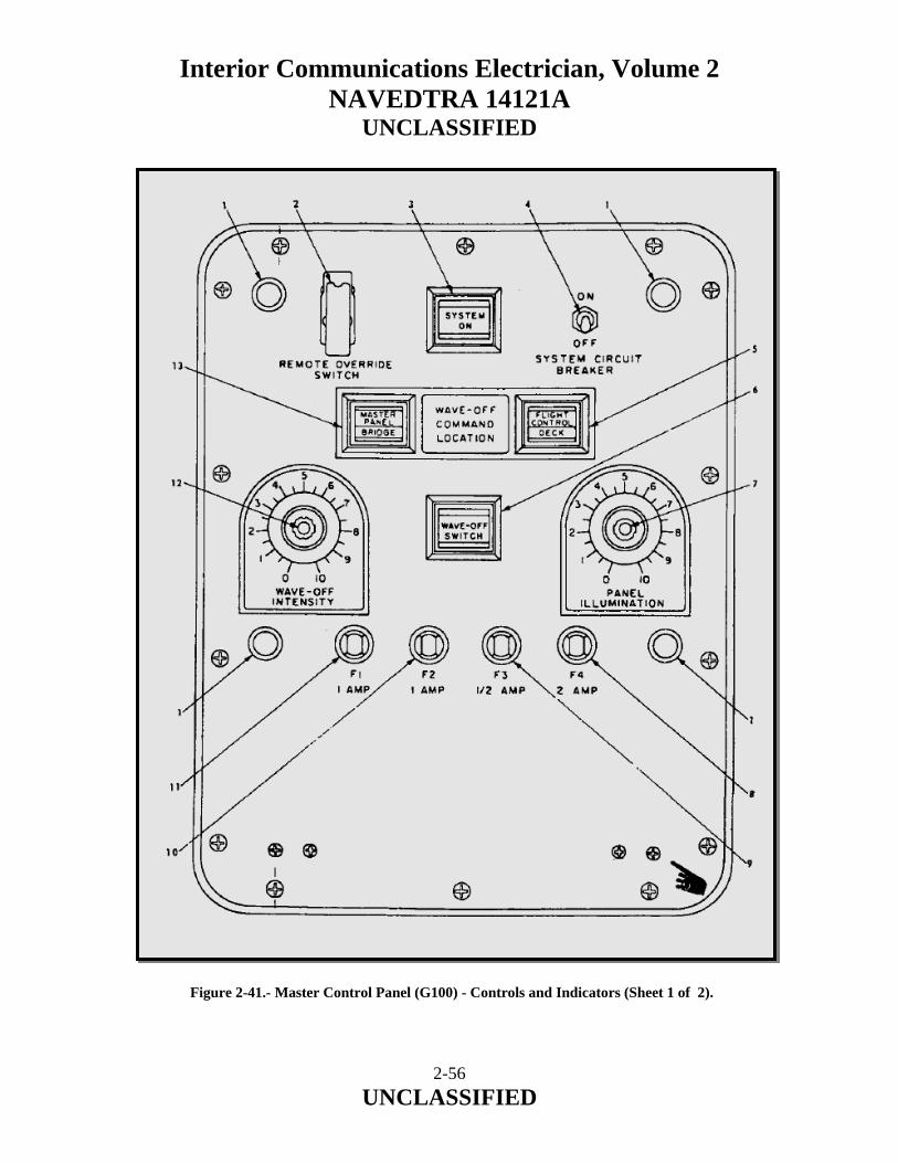
Interior Communications Electrician, Volume 2 NAVEDTRA 14121A
UNCLASSIFIED
Figure 2-41.- Master Control Panel (G100) - Controls and Indicators (Sheet 1 of 2).
2-56 UNCLASSIFIED
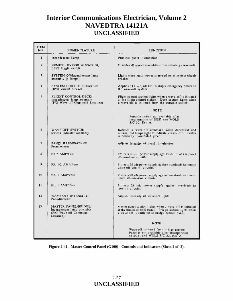
Interior Communications Electrician, Volume 2 NAVEDTRA 14121A
UNCLASSIFIED
Figure 2-41.- Master Control Panel (G100) - Controls and Indicators (Sheet 2 of 2).
2-57 UNCLASSIFIED

Interior Communications Electrician, Volume 2 NAVEDTRA 14121A
UNCLASSIFIED
2.3.11 Safety Precautions The safety precautions given in the following warning are to he strictly adhered to by all personnel coming in contact with the wave-off system. WARNING Voltages which are dangerous to life are used in the Wave-off Light System. Before applying power to the Wave-off Light System, all covers and panels must he secured. 2.3.12 System Initial Control Settings Information concerning the proper initial control settings and the preferred order in which to make these settings is provided in Table 2-2.
ASSEMBLY CONTROL POSITION Master Control Panel (G 100)
SYSTEM CIRCUIT BREAKER REMOTE OVERRIDE SWITCH WAVE·OFF INTENSITY PANEL ILLUMINATION
OFF Normal Set at 50% Full CW (maximum intensity)
Remote Panel (G200 and G200A)
INTENSITY Full CW (maximum intensity)
Table 2-2.- System Initial Control Settings. 2.3.13 System Turn-On Procedure The system turn-on procedure, which is performed after the controls are initially set, is accomplished by following the steps as outlined in Table 2-3. 2.3.14 System Normal and Remote Operation Modes At the completion of the turn-on procedure, as described in Table 2-3, the Wave-off Light System is in the normal mode of operation. In the normal mode of operation, wave-off may be initiated from I anyone of three locations. They are: master control panel and remote panels (G200 and G200A).
2-58 UNCLASSIFIED

Interior Communications Electrician, Volume 2 NAVEDTRA 14121A
UNCLASSIFIED
STEP ASSEMBLY CONTROL SETTINGS
AND INSTRUCTION NORMAL INDICATION
1 Master Control Panel (G1OO).
Place SYSTEM CIRCUIT BREAKER in ON position.
SYSTEM ON indicator lights. Panel illumination lamps light. At Remote Panel G200 and G200A: SYSTEM ON indicator lights.
2 Press WAVE-OFF SWITCH. NOTE
Prior to incorporation of SOSI and WOLS SIC 32, Rev A, wave-off may he initiated from either of the remote panels, not available after this SIC is incorporated.
Master panel WAVE-OFF indicator flashes.
NOTE When wave-off is initiated from either the remote panels or the portable switch, the respective location indicator on the master control panel will illuminate. At Wave-off Light: Wave-off lights flash. At Remote Panel: WAVE-OFF indicator light flashes.
3 Adjust WAVE-OFF INTENSITY control
At Wave-off Lights: Wave-off lights vary intensity
4 Press wave-off switch Wave-off lights will extinguish.
Table 2-3.- System Turn-On Procedure. The remote override mode of operation is used when wave-off initiation from a remote location is to be prevented or overridden. To place the system in the override mode of operation, raise the switch guard on the REMOTE OVERRIDE SWITCH (2, Figure 2-41) and place switch SW2 in the "UP" (override) position. The remote panel wave-off switches are now out of I the circuit; however, wave-off may still be initiated from the master control panel. To remove the system from the remote override mode, press switch SW 2 "DOWN" and lower the switch guard.
2-59 UNCLASSIFIED

Interior Communications Electrician, Volume 2 NAVEDTRA 14121A
UNCLASSIFIED
2.3.15 System Turnoff Procedure When helicopter operations are complete, refer to the following for proper Wave-off Light System turnoff procedures.
1. Remove wave-off system from the flash mode by pressing the wave-off switch that originally initiated the wave-off.
NOTE The switch which initiated the wave-off will be indicated by its respective indicator on the master panel. 2. Place the SYSTEM CIRCUIT BREAKER on the master control panel in the "OFF" position.
2.4.0 WAVE-OFF LIGHT SYSTEM MK 1 MOD 0 FOR LAMPS MK III EQUIPPED SHIPS The wave-off system for LAMPS Mk III equipped ships functions fundamentally the same as the Mk 1 Mod 0 described in the previous section. However, there are subtle differences which are described in this section. The primary difference is the interface with other shipboard systems. (For an overall system illustration, see figure 2-42.) 2.4.1 Interface with other Systems The Wave-off Light System MK 1 MOD 0 is interfaced with the Flight Deck Status and Signaling System (FDSSS) and Recovery Assist, Secure, and Traverse (RAST) Systems. The Deck Status Lights are also tied in with the overall operation. See block diagram figure 2-43. The Wave-off Light System Master Control Panel is interconnected to the FDSSS Interface Control Unit. The Wave-off Light System and the FDSSS System are installed aboard air capable ships equipped for LAMPS Mark III operations. The FDSSS System enables the Helicopter Control Officer (HCO), at the Helicopter Control Station (HCS), to request and receive launch and recovery authorization from the Bridge and/or CIC. The FDSSS also incorporates control of the deck status lights at the (HCS) and provides status indications at the Bridge and CIC. Capability 10 control the wave-off lights via the Wave-off Lights System is incorporated in all units, except from the bridge and/or CIC units.
2-60 UNCLASSIFIED
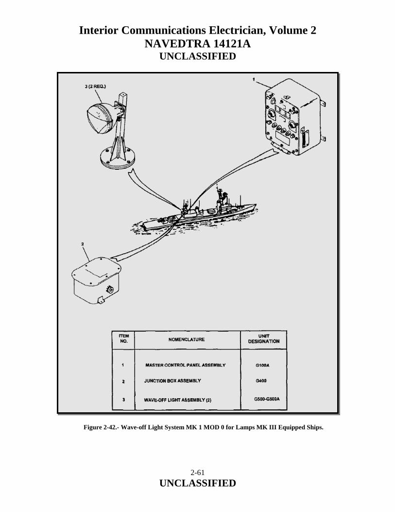
Interior Communications Electrician, Volume 2 NAVEDTRA 14121A
UNCLASSIFIED
Figure 2-42.- Wave-off Light System MK 1 MOD 0 for Lamps MK III Equipped Ships.
2-61 UNCLASSIFIED
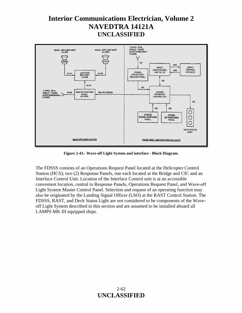
Interior Communications Electrician, Volume 2 NAVEDTRA 14121A
UNCLASSIFIED
Figure 2-43.- Wave-off Light System and interface - Block Diagram. The FDSSS consists of an Operations Request Panel located at the Helicopter Control Station (HCS); two (2) Response Panels, one each located at the Bridge and CIC and an Interface Control Unit. Location of the Interface Control unit is at an accessible convenient location, central to Response Panels, Operations Request Panel, and Wave-off Light System Master Control Panel. Selection and request of an operating function may also be originated by the Landing Signal Officer (LSO) at the RAST Control Station. The FDSSS, RAST, and Deck Status Light are not considered to be components of the Wave-off Light System described in this section and are assumed to be installed aboard all LAMPS MK III equipped ships.
2-62 UNCLASSIFIED

Interior Communications Electrician, Volume 2 NAVEDTRA 14121A
UNCLASSIFIED
2.4.2 Principal of Operation The Wave-off Light System indicates when a dangerous or potentially dangerous situation exists and the helicopter should abort its approach. The wave-off lights are installed on either side of the stabilized glide slope indicator and located parallel to the approach line on single-approach ships. The wave-off lights flash at 90 flashes per minute and are variable in intensity. In addition to providing the lamp flasher, a monitor circuit is incorporated into the system. It senses wave-off lamp voltage and wave-off command locations. This information is then displayed on the master control panel. Additionally, the wave-off indications are transmitted to the FDSSS and RAST Control Panel. The monitor card receives all the wave-off commands from the FDSSS and RAST Control Panel and drives Master Control Panel lamps to indicate which switch was pushed. It also drives the panel dimmer, provides a wave-off output to the flasher/driver card, senses voltage across the wave-off lamps, and provides a positive indication of a wave-off at all panels. Because of the interrelationship of the Wave-off Light System with the FDSSS, RAST, and Deck Status Light, pertinent interface data is included. 2.4.3 Wave-Off Light System Controls, Indicators and Fuses Controls, indicators, and fuses located on the Master Control Panel (G100A) are shown and listed in figure 2-44. This information will enable maintenance personnel to locate, identify, and understand the function of the Wave-off Light System.
2-63 UNCLASSIFIED
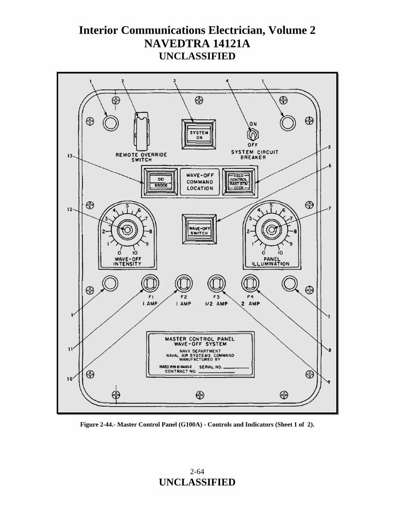
Interior Communications Electrician, Volume 2 NAVEDTRA 14121A
UNCLASSIFIED
Figure 2-44.- Master Control Panel (G100A) - Controls and Indicators (Sheet 1 of 2).
2-64 UNCLASSIFIED

Interior Communications Electrician, Volume 2 NAVEDTRA 14121A
UNCLASSIFIED
Figure 2-44.- Master Control Panel (G100A) - Controls and Indicators (Sheet 2 of 2).
2-65 UNCLASSIFIED

Interior Communications Electrician, Volume 2 NAVEDTRA 14121A
UNCLASSIFIED
2.4.4 Safety Precautions The safety precautions given in the following warning are to be strictly adhered to by all personnel coming in contact with the wave-off system. WARNING Voltages which are dangerous to life are used in the Wave-off Light System. Before applying power to the Wave-off Light System, all covers and panels must be secured. 2.4.5 Wave-Off Light System Operation INITIAL CONTROL SETTINGS Information concerning the Wave-off Light System initial control settings and the preferred order in which to make these settings is provided in table 2-4. STEP CONTROL POSITION
MASTER CONTROL PANEL (G100A) 1 SYSTEM CIRCUIT BREAKER (CB-1) OFF 2 REMOTE OVERRIDE SWITCH (SW-2) Normal 3 WAVE-OFF INTENSITY (R-l) Set at 5 (Midpoint) 4 PANEL ILLUMINATION (R-2) Set at 10 (Full clockwise, for max.
intensity) Table 2-4.- Wave-off Light System -Initial Control Settings.
2-66 UNCLASSIFIED

Interior Communications Electrician, Volume 2 NAVEDTRA 14121A
UNCLASSIFIED
TURNON PROCEDURE The Wave-off Light System turn-on procedures, performed after the controls are initially set, is accomplished by following the steps outlined in table 2-5. The system is then ready for operation. STEP CONTROL SETTINGS AND
INSTRUCTIONS NORMAL INDICATION
Master Control Panel (G100A) 1 Place SYSTEM CIRCUIT
BREAKER in ON position. SYSTEM ON indicator lights Panel illumination lamps light
2 Press WAVE-OFF SWITCH
NOTE
Wave-off may also be initiated from FDSSS and RAST systems.
Master Control Panel WAVE-OFF indicator flashes NOTE When wave-off is initiated from a point other than the Master Control Panel, the respective location indicator on the Master Control Panel will illuminate. Wave-off Lights (G500 and G5OOA) flash
3 Adjust WAVE-OFF INTENSITY control.
Wave-off Lights (G500 and G500A) vary intensity.
4 Press WAVE-OFF SWITCH Wave-off Lights extinguish.
Table 2-5.- Wave-off Light System -Initial Control Settings. 2.4.6 Normal and Remote Operation Modes Normal Operation Mode At the completion of the turn-on procedure, the Wave-off Light System is in the normal mode of operation. When in the normal mode of operation, wave-off may be initiated from any one of following locations:
a. Master Control Panel (G100A) at the HCS. b. FDSSS Operations Request Panel at the HCS. c. RAST Control Console at the LSO Station.
2-67 UNCLASSIFIED

Interior Communications Electrician, Volume 2 NAVEDTRA 14121A
UNCLASSIFIED
Remote Override Mode When the remote override mode of operation is used, wave-off initiation from a remote location is prevented or overridden. To initiate the override mode, lift the switch guard on the REMOTE OVERRIDE SWITCH (2, figure 2-44) and place switch in the "UP" (override) position. The remote switches are disabled (out of the circuit); however, wave-off can be initiated at the HCS by depressing the WAVEOFF SWITCH (6, figure 2-44) located on the Master Control Panel (G100A). To return the system to the normal mode, raise the switch guard on the REMOTE OVERRIDE SWITCH and set switch to "DOWN". 2.4.7 FDSSS and RAST Systems Controls and Indicators Interfacing systems must be turned on and operational in order to initiate a remote wave-off. The Wave-off Light System is in the normal mode. Controls and indicators for the FDSSS and RAST systems, along with listings of their function are provided in figures 2-45 through 2-47. An understanding of their normal function and operation is essential to personnel engaged in operation and maintenance of the Wave-off Light System.
Figure 2-45.- FDSSS Operations Request Panel - Controls and Indicators (Sheet 1of 3).
2-68 UNCLASSIFIED
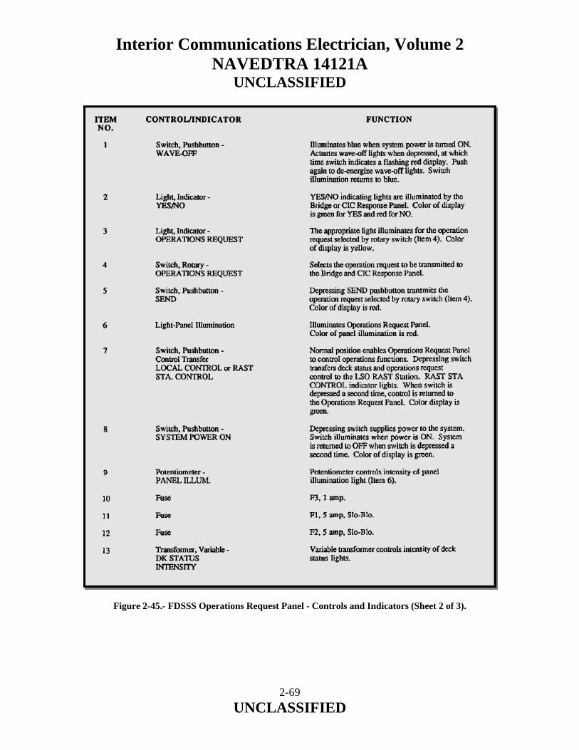
Interior Communications Electrician, Volume 2 NAVEDTRA 14121A
UNCLASSIFIED
Figure 2-45.- FDSSS Operations Request Panel - Controls and Indicators (Sheet 2 of 3).
2-69 UNCLASSIFIED
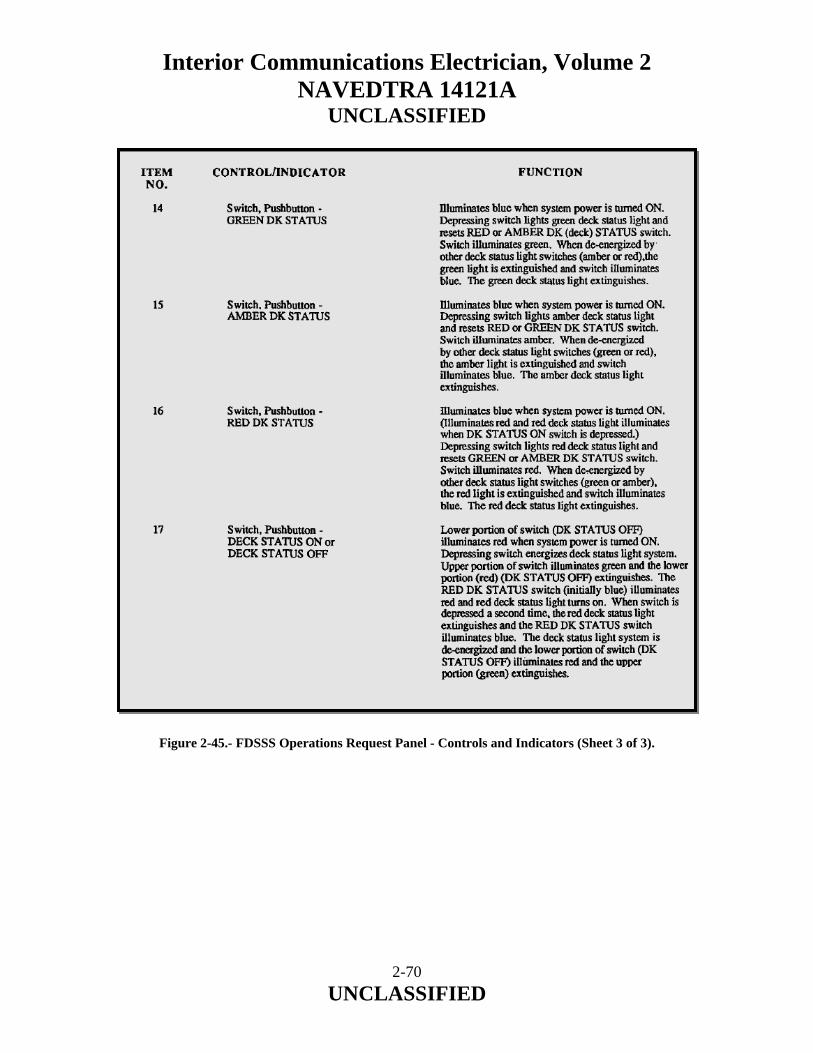
Interior Communications Electrician, Volume 2 NAVEDTRA 14121A
UNCLASSIFIED
Figure 2-45.- FDSSS Operations Request Panel - Controls and Indicators (Sheet 3 of 3).
2-70 UNCLASSIFIED
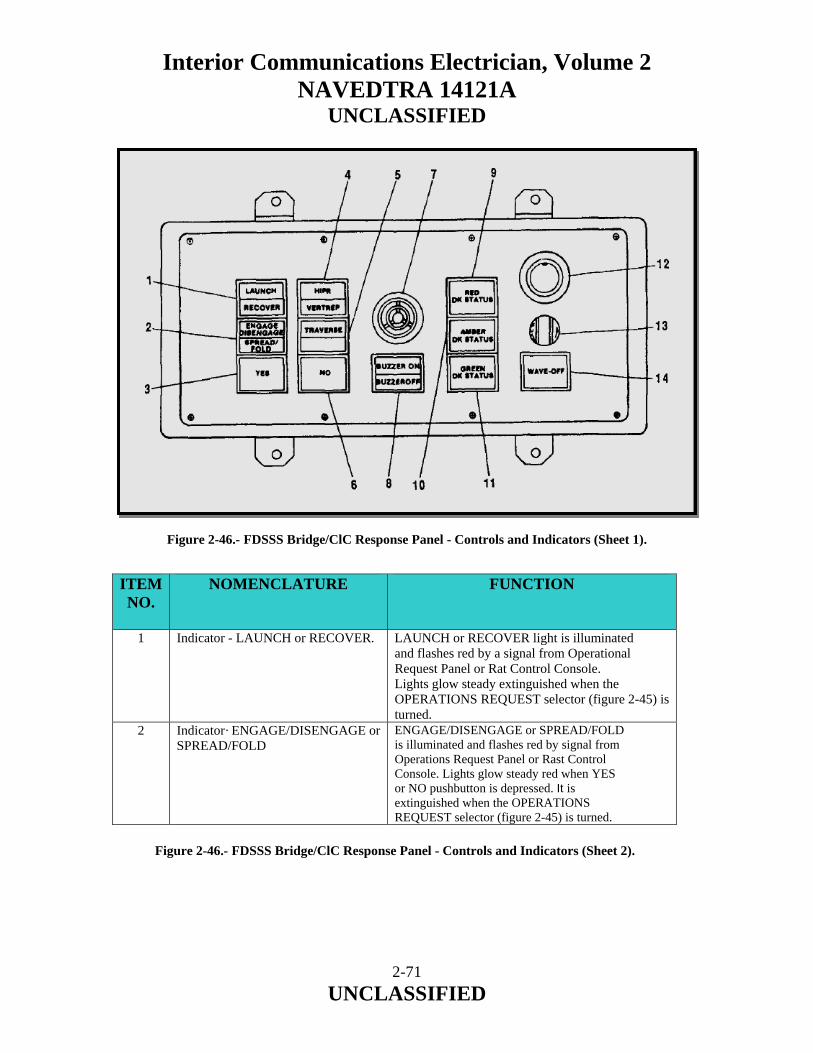
Interior Communications Electrician, Volume 2 NAVEDTRA 14121A
UNCLASSIFIED
Figure 2-46.- FDSSS Bridge/ClC Response Panel - Controls and Indicators (Sheet 1). ITEM NO.
NOMENCLATURE FUNCTION
1 Indicator - LAUNCH or RECOVER. LAUNCH or RECOVER light is illuminated and flashes red by a signal from Operational Request Panel or Rat Control Console. Lights glow steady extinguished when the OPERATIONS REQUEST selector (figure 2-45) is turned.
2 Indicator· ENGAGE/DISENGAGE or SPREAD/FOLD
ENGAGE/DISENGAGE or SPREAD/FOLD is illuminated and flashes red by signal from Operations Request Panel or Rast Control Console. Lights glow steady red when YES or NO pushbutton is depressed. It is extinguished when the OPERATIONS REQUEST selector (figure 2-45) is turned.
Figure 2-46.- FDSSS Bridge/ClC Response Panel - Controls and Indicators (Sheet 2).
2-71 UNCLASSIFIED
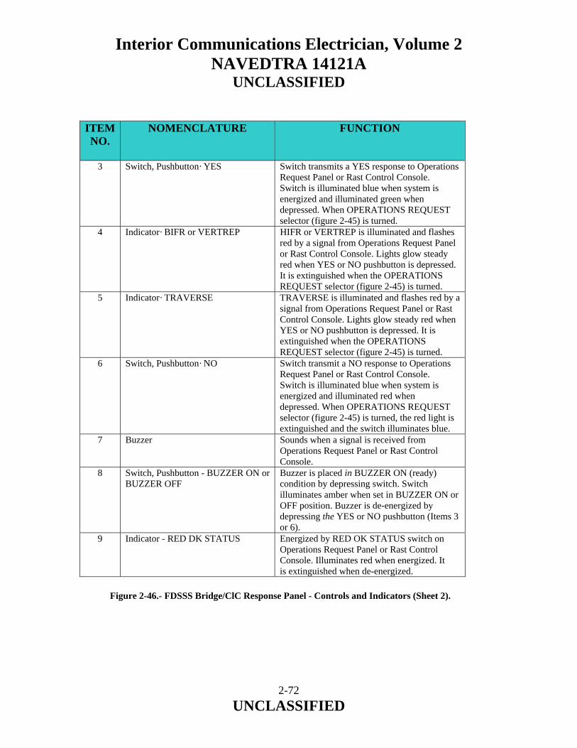
Interior Communications Electrician, Volume 2 NAVEDTRA 14121A
UNCLASSIFIED
ITEM NO.
NOMENCLATURE FUNCTION
3 Switch, Pushbutton· YES Switch transmits a YES response to Operations Request Panel or Rast Control Console. Switch is illuminated blue when system is energized and illuminated green when depressed. When OPERATIONS REQUEST selector (figure 2-45) is turned.
4 Indicator· BIFR or VERTREP HIFR or VERTREP is illuminated and flashes red by a signal from Operations Request Panel or Rast Control Console. Lights glow steady red when YES or NO pushbutton is depressed. It is extinguished when the OPERATIONS REQUEST selector (figure 2-45) is turned.
5 Indicator· TRAVERSE TRAVERSE is illuminated and flashes red by a signal from Operations Request Panel or Rast Control Console. Lights glow steady red when YES or NO pushbutton is depressed. It is extinguished when the OPERATIONS REQUEST selector (figure 2-45) is turned.
6 Switch, Pushbutton· NO Switch transmit a NO response to Operations Request Panel or Rast Control Console. Switch is illuminated blue when system is energized and illuminated red when depressed. When OPERATIONS REQUEST selector (figure 2-45) is turned, the red light is extinguished and the switch illuminates blue.
7 Buzzer Sounds when a signal is received from Operations Request Panel or Rast Control Console.
8 Switch, Pushbutton - BUZZER ON or BUZZER OFF
Buzzer is placed in BUZZER ON (ready) condition by depressing switch. Switch illuminates amber when set in BUZZER ON or OFF position. Buzzer is de-energized by depressing the YES or NO pushbutton (Items 3 or 6).
9 Indicator - RED DK STATUS Energized by RED OK STATUS switch on Operations Request Panel or Rast Control Console. Illuminates red when energized. It is extinguished when de-energized.
Figure 2-46.- FDSSS Bridge/ClC Response Panel - Controls and Indicators (Sheet 2).
2-72 UNCLASSIFIED
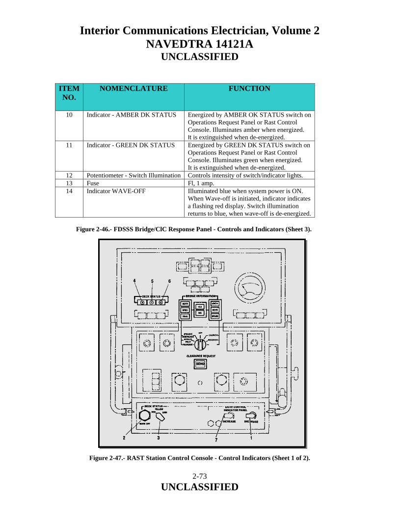
Interior Communications Electrician, Volume 2 NAVEDTRA 14121A
UNCLASSIFIED
ITEM NO.
NOMENCLATURE FUNCTION
10 Indicator - AMBER DK STATUS Energized by AMBER OK STATUS switch on Operations Request Panel or Rast Control Console. Illuminates amber when energized. It is extinguished when de-energized.
11 Indicator - GREEN DK STATUS Energized by GREEN DK STATUS switch on Operations Request Panel or Rast Control Console. Illuminates green when energized. It is extinguished when de-energized.
12 Potentiometer - Switch Illumination Controls intensity of switch/indicator lights. 13 Fuse Fl, 1 amp. 14 Indicator WAVE-OFF Illuminated blue when system power is ON.
When Wave-off is initiated, indicator indicates a flashing red display. Switch illumination returns to blue, when wave-off is de-energized.
Figure 2-46.- FDSSS Bridge/ClC Response Panel - Controls and Indicators (Sheet 3).
Figure 2-47.- RAST Station Control Console - Control Indicators (Sheet 1 of 2).
2-73 UNCLASSIFIED
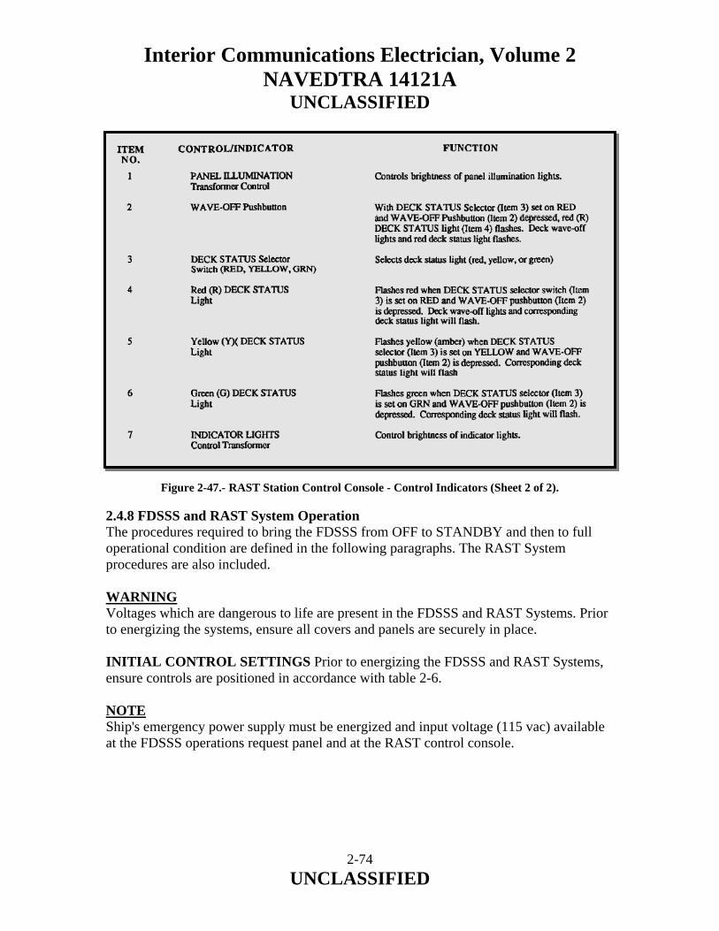
Interior Communications Electrician, Volume 2 NAVEDTRA 14121A
UNCLASSIFIED
Figure 2-47.- RAST Station Control Console - Control Indicators (Sheet 2 of 2). 2.4.8 FDSSS and RAST System Operation The procedures required to bring the FDSSS from OFF to STANDBY and then to full operational condition are defined in the following paragraphs. The RAST System procedures are also included. WARNING Voltages which are dangerous to life are present in the FDSSS and RAST Systems. Prior to energizing the systems, ensure all covers and panels are securely in place. INITIAL CONTROL SETTINGS Prior to energizing the FDSSS and RAST Systems, ensure controls are positioned in accordance with table 2-6. NOTE Ship's emergency power supply must be energized and input voltage (115 vac) available at the FDSSS operations request panel and at the RAST control console.
2-74 UNCLASSIFIED

Interior Communications Electrician, Volume 2 NAVEDTRA 14121A
UNCLASSIFIED
ASSEMBLY CONTROL FIGURE
NO. ITEMNO.
POSITION
FDSSS Operations Request Panel
OPERATIONS REQUEST function selector (rotary) switch
3 4 OFF
PANEL ILLUM. potentiometer
3 9 Full clockwise (maximum intensity)
DK STATUS INTENSITY 3 13 50 percent intensity position
FDSSS Bridge/CIC Response Panel
Switch/indicator illumination potentiometer
4 12 Full clockwise (maximum intensity)
RAST Machinery Space
RAST Power ON/OFF switch
"OFF" position
Test Control Panel local remote switch
Set to remote position
RAST Station Control Console
Panel illumination potentiometer
5 2 50 percent intensity position
Table 2-6.- FDSSS and RAST Systems -Initial Control Settings.
2.4.9 Turn-on Procedures To energize the FDSSS and RAST Systems, proceed according to the procedure provided in table 2-7. At completion the systems are in standby and ready for operation. 2.4.10 System Turn-off When helicopter operations are complete, turnoff the Wave-off Light FDSSS and RAST Systems as follows:
a. Remove Wave-off Light System from the flash mode by pressing the wave-off switch at the location of wave-off initiation.
NOTE The switch which initiated wave-off will be indicated by the respective indicator on the Master Control Panel.
b. Set SYSTEM CIRCUIT BREAKER (CB- 1) on Master Control Panel (GIOOA) to OFF. c. De-energize FDSSS Operations Request Panel by depressing SYSTEM POWER ON switch; panel lights will extinguish. d. Set local/remote switch located in the RAST machinery space on the winch hydraulic unit to remote.
2-75 UNCLASSIFIED
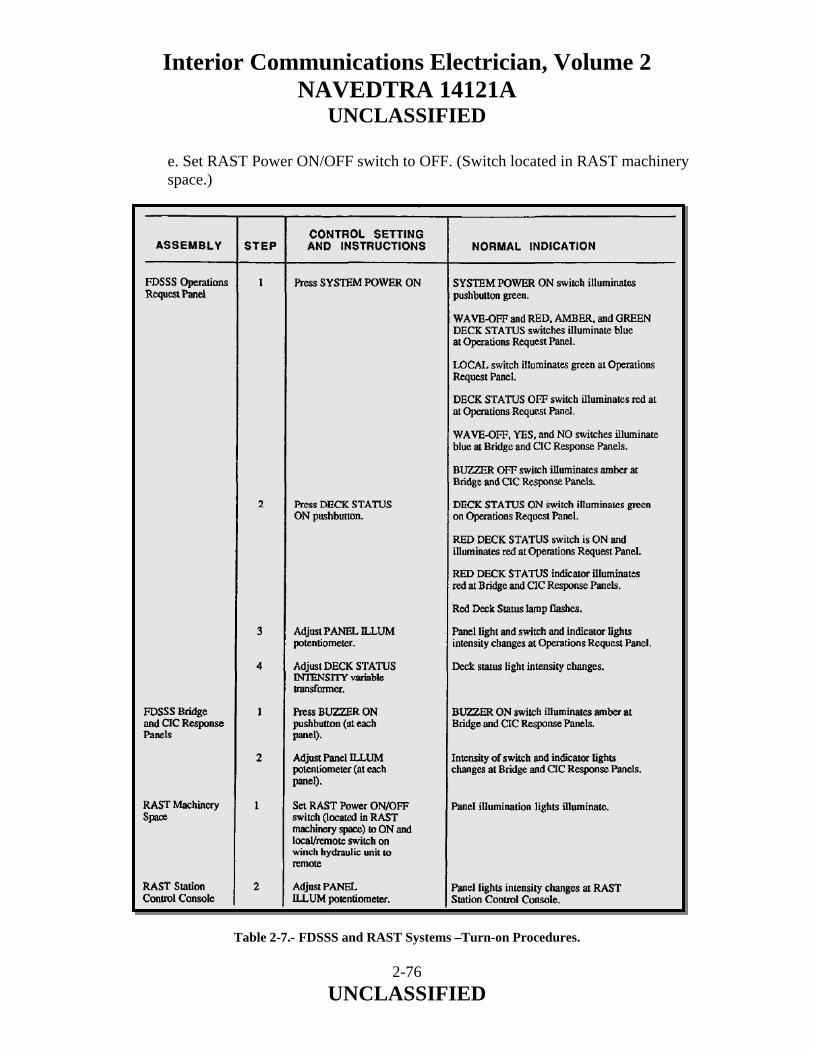
Interior Communications Electrician, Volume 2 NAVEDTRA 14121A
UNCLASSIFIED
e. Set RAST Power ON/OFF switch to OFF. (Switch located in RAST machinery space.)
Table 2-7.- FDSSS and RAST Systems –Turn-on Procedures.
2-76 UNCLASSIFIED
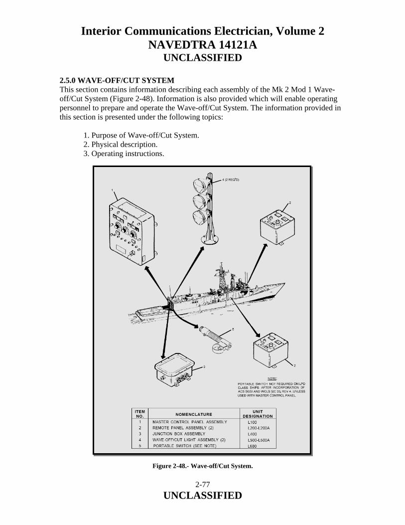
Interior Communications Electrician, Volume 2 NAVEDTRA 14121A
UNCLASSIFIED
2.5.0 WAVE-OFF/CUT SYSTEM This section contains information describing each assembly of the Mk 2 Mod 1 Wave-off/Cut System (Figure 2-48). Information is also provided which will enable operating personnel to prepare and operate the Wave-off/Cut System. The information provided in this section is presented under the following topics:
1. Purpose of Wave-off/Cut System. 2. Physical description. 3. Operating instructions.
Figure 2-48.- Wave-off/Cut System.
2-77 UNCLASSIFIED

Interior Communications Electrician, Volume 2 NAVEDTRA 14121A
UNCLASSIFIED
2.5.1 Purpose of Wave-Off/Cut System The Wave-off/Cut System is an electronic system designed for use on LPH-2, LPH-4, LHA-1, LHD-1, LPD-1 and LPD-4 class ships in conjunction with an optical landing aid providing glide path information. When the wave-off lights are flashing, it is an indication to the pilot that he is to abort the landing and initiate a new landing approach. The cut lights are used as signal lights to communicate specific messages to the pilot in the event of radio communication loss. A wave-off/cut light assembly is mounted on each side of the appropriate optical landing aid providing glide path information. The light assemblies are located in accordance with the ships installation guidance drawing. 2.5.2 Physical Description A detailed description of the Wave-off/Cut System is provided. The assemblies that comprise the system together with their unit numbers are as follows:
1. Master control panel assembly (L100) 2. Remote panel assembly (L200, L200A) 3. Junction box assembly (L400) 4. Wave-off/cut light assembly (L500, L500A) 5. Portable switch assembly (L600)
NOTE L600 not required for LPD class after incorporation of ACS SGSI and WOLS S/C 33, Rev A, unless used with master control panel. 2.5.3 Technical Characteristics The technical characteristics of the Wave-off/Cut System are listed in Table 2-8.
2-78 UNCLASSIFIED
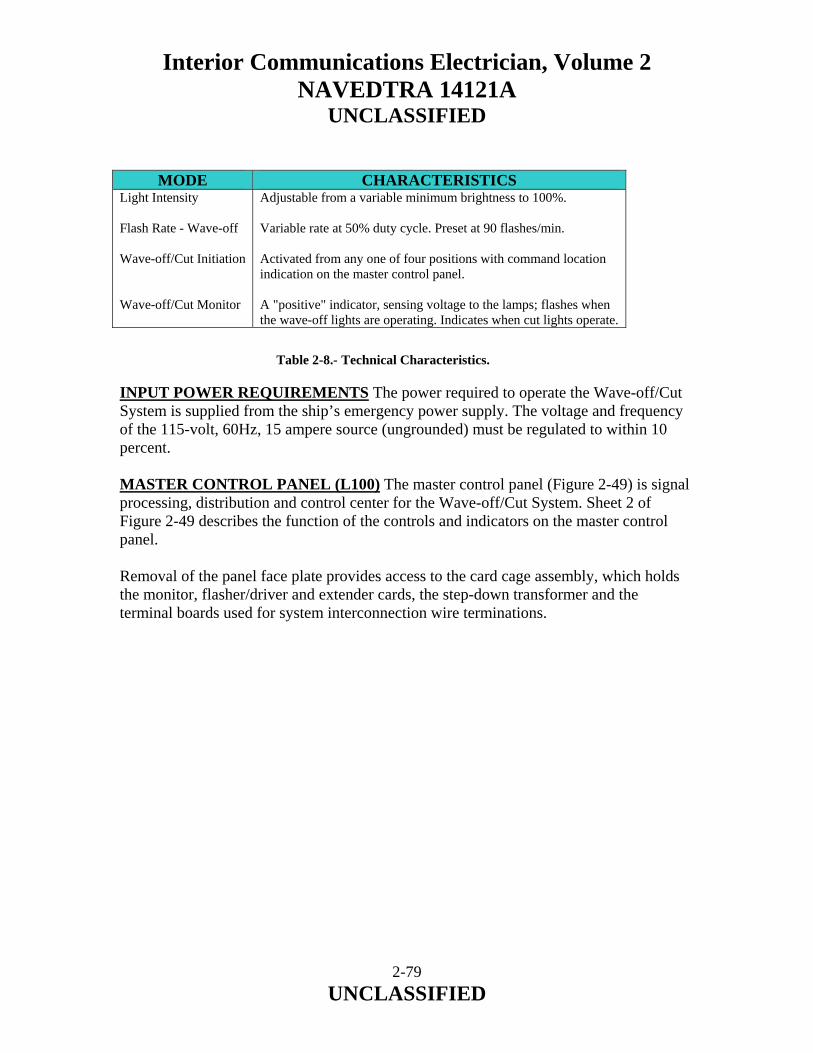
Interior Communications Electrician, Volume 2 NAVEDTRA 14121A
UNCLASSIFIED
MODE CHARACTERISTICS
Light Intensity Flash Rate - Wave-off Wave-off/Cut Initiation Wave-off/Cut Monitor
Adjustable from a variable minimum brightness to 100%. Variable rate at 50% duty cycle. Preset at 90 flashes/min. Activated from any one of four positions with command location indication on the master control panel. A "positive" indicator, sensing voltage to the lamps; flashes when the wave-off lights are operating. Indicates when cut lights operate.
Table 2-8.- Technical Characteristics. INPUT POWER REQUIREMENTS The power required to operate the Wave-off/Cut System is supplied from the ship’s emergency power supply. The voltage and frequency of the 115-volt, 60Hz, 15 ampere source (ungrounded) must be regulated to within 10 percent. MASTER CONTROL PANEL (L100) The master control panel (Figure 2-49) is signal processing, distribution and control center for the Wave-off/Cut System. Sheet 2 of Figure 2-49 describes the function of the controls and indicators on the master control panel. Removal of the panel face plate provides access to the card cage assembly, which holds the monitor, flasher/driver and extender cards, the step-down transformer and the terminal boards used for system interconnection wire terminations.
2-79 UNCLASSIFIED
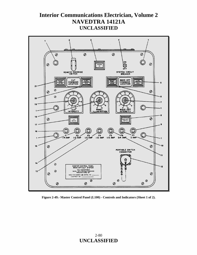
Interior Communications Electrician, Volume 2 NAVEDTRA 14121A
UNCLASSIFIED
Figure 2-49.- Master Control Panel (L100) - Controls and Indicators (Sheet 1 of 2).
2-80 UNCLASSIFIED
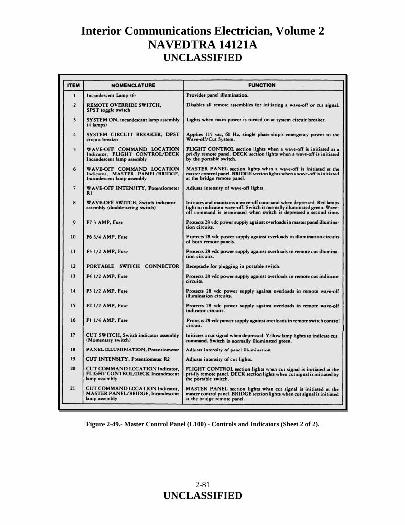
Interior Communications Electrician, Volume 2 NAVEDTRA 14121A
UNCLASSIFIED
Figure 2-49.- Master Control Panel (L100) - Controls and Indicators (Sheet 2 of 2).
2-81 UNCLASSIFIED
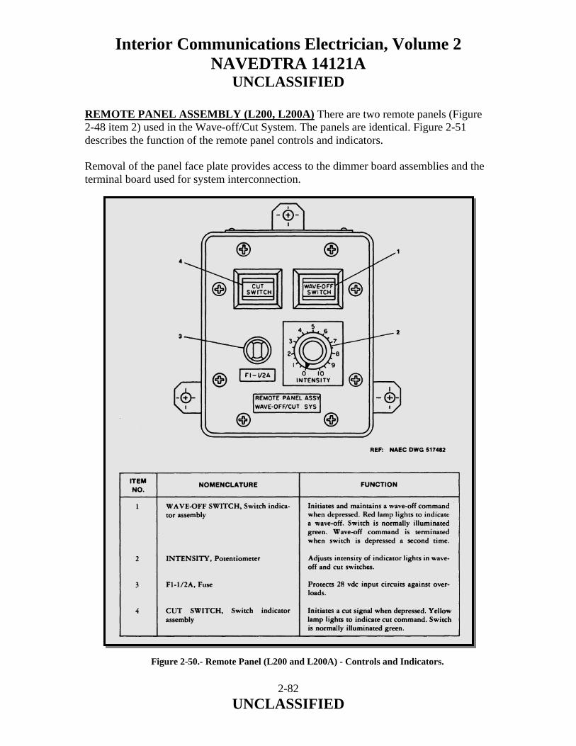
Interior Communications Electrician, Volume 2 NAVEDTRA 14121A
UNCLASSIFIED
REMOTE PANEL ASSEMBLY (L200, L200A) There are two remote panels (Figure 2-48 item 2) used in the Wave-off/Cut System. The panels are identical. Figure 2-51 describes the function of the remote panel controls and indicators. Removal of the panel face plate provides access to the dimmer board assemblies and the terminal board used for system interconnection.
Figure 2-50.- Remote Panel (L200 and L200A) - Controls and Indicators.
2-82 UNCLASSIFIED

Interior Communications Electrician, Volume 2 NAVEDTRA 14121A
UNCLASSIFIED
JUNCTION BOX ASSEMBLY (L400) Junction box assembly L-400 (Figure 2-48) is a moisture and dust proof unit which provides the means for connecting the cable from the master control panel to the wave-off/cut light cables. It is located within ten feet of the wave-off/ cut light assemblies. WAVE-OFF/CUT LIGHT ASSEMBLY (L500, L500A) The wave-off/cut light assemblies (Figure 2-48) are identical units, which are installed one on each side of the stabilized platform. System interconnecting cabling connects by way of a connector located at the rear of each lamp housing. This connector has a cover, attached, with a retaining chain, which is used to prevent moisture and dirt from entering the connector when the interconnecting cable is not attached. NOTE Portable switch is not required for LPD class after incorporation of ACS SGSI and WOLS S/C 33, Rev A, unless used with master control panel. PORTABLE SWITCH ASSEMBLY (L600) The portable switch (Figure 2-51) is a hand-held unit which can be connected directly to the master control panel (L100). Figure 2-51 describes the function of the switches on the portable switch assembly. 2.5.4 Operating Instructions Information is provided for operating the Wave-off/Cut System in normal and remote operational mode. This information is presented under the following topics:
1. System controls, indicators, and fuses 2. Safety precautions 3. System initial control settings 4. System turn-on procedure 5. System normal and remote operation modes 6. System turnoff procedure
SYSTEM CONTROLS AND INDICATORS The information necessary to familiarize personnel with the operating controls, indicators, and fuses is presented in Figures 2-49, 2-50, and 2-51. The information provided in these figures will enable personnel to locate, identify, and understand the function of each component listed.
2-83 UNCLASSIFIED

Interior Communications Electrician, Volume 2 NAVEDTRA 14121A
UNCLASSIFIED
Figure 2-51.- Portable Switch (L600) - Controls.
2-84 UNCLASSIFIED

Interior Communications Electrician, Volume 2 NAVEDTRA 14121A
UNCLASSIFIED
2.5.5 Safety Precautions The safety precautions given in the following warning are to be strictly adhered to by all personnel coming in contact with the Wave-off/Cut System. WARNING Voltages which are dangerous to life are used in the Wave-off/Cut System. Before applying power to the Wave-off/Cut System, all covers and panels must be secured. 2.5.6 System Initial Control Settings Information concerning the proper initial control settings and the preferred order in which to make these settings is provided in Table 2-9. ASSEMBLY CONTROL POSITION
Master Control Panel (L100) Remote Panel (L200 and L200A)
SYSTEM CIRCUIT BREAKER REMOTE OVERRIDE SWITCH CUT INTENSITY PANEL ILLUMINATION WAVE-OFF INTENSITY INTENSITY
OFF Normal, Toggle down Set at 50% Full CW (max intensity) Set at 50% Full CW (max intensity)
Table 2-9.- System Initial Controls Settings.
2.5.7 System Turn-on Procedure The system turn-on procedure, which is performed after the controls are initially set, is accomplished by following the steps as outlined in Table 2-10. 2.5.8 System Normal and Remote Operating Modes At the completion of the turn-on procedure, as described in Table 2-10, the Wave-off/ Cut System is in the normal mode of operation. In the normal mode of operation, wave-off or cut signals may be initiated from any one of four locations. They are: master control panel, remote panels (L200 and L200A) and portable switch. The remote override mode of operation is used when wave-off initiation from a remote location is to be prevented or overridden. To place the system in the remote (override) mode of operation, raise the switch guard on the REMOTE OVERRIDE SWITCH (2, Figure 2-49) and place switch in the "UP" (override) position. The remote panel wave-off and cut switches and the portable switch are now out of the circuit; however, wave-off or cut signals may still be initiated from the master control panel.
2-85 UNCLASSIFIED
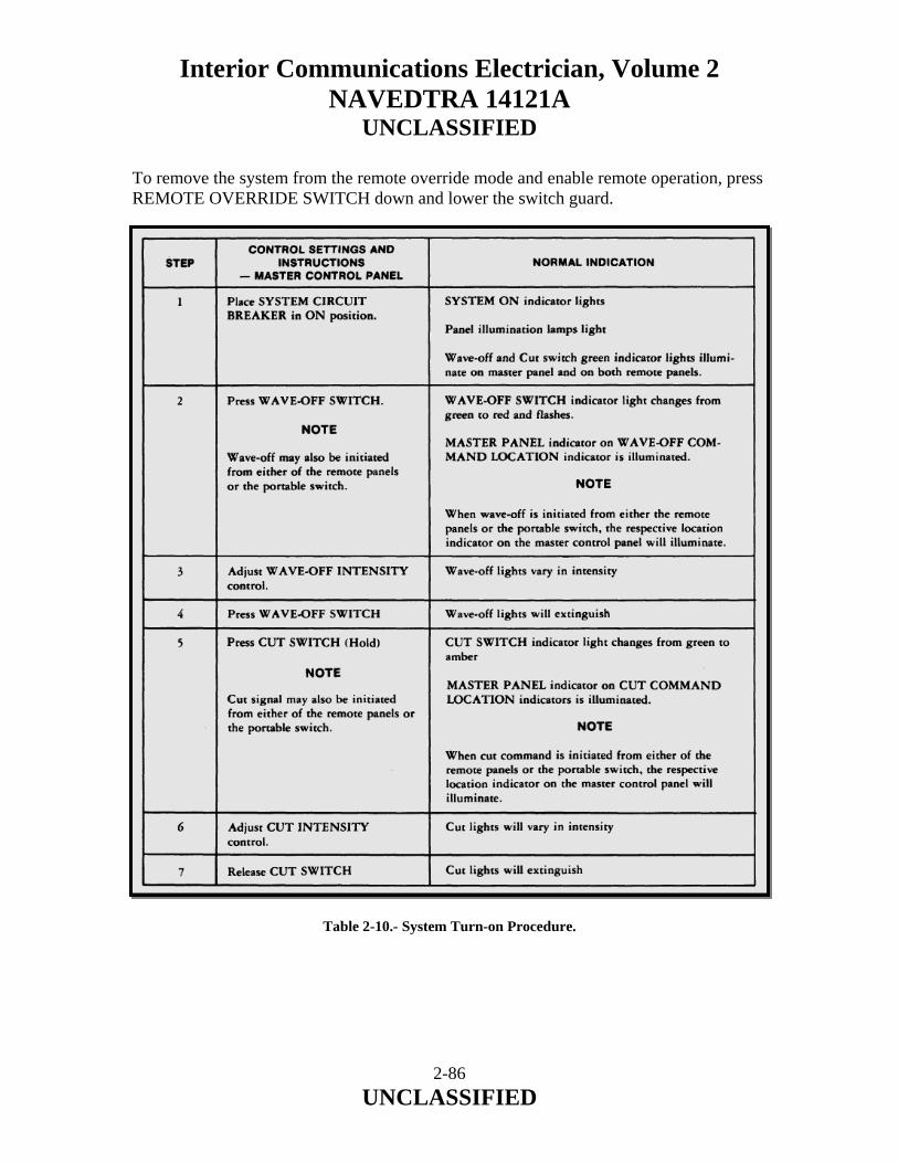
Interior Communications Electrician, Volume 2 NAVEDTRA 14121A
UNCLASSIFIED
To remove the system from the remote override mode and enable remote operation, press REMOTE OVERRIDE SWITCH down and lower the switch guard. Table 2-10.- System Turn-on Procedure.
2-86 UNCLASSIFIED

Interior Communications Electrician, Volume 2 NAVEDTRA 14121A
UNCLASSIFIED
2.5.9 System Turnoff Procedure When helicopter operations are complete, refer to the following for proper Wave-off/Cut System turnoff procedures.
1. Remove wave-off system from the flash mode by pressing the wave-off switch that originally initiated the wave-off.
NOTE The switch which initiated the wave-off will be indicated by its respective indicator on the master panel.
2. Place the SYSTEM CIRCUIT BREAKER on the master control panel in the "OFF" position.
2.5.10 Theory of Operation This section discusses the theory of operation of the Wave-off/Cut System. It includes diagrams of the various components to aid in the understanding of the text. WAVE-OFF/CUT CIRCUITS A block diagram of the Wave-off/Cut System is shown in Figure 2-52. The master control panel (L100) is located in the pri-fly flight control station along with the pri-fly remote panel (L200A). Wave-off and cut lamps (L500 and L500A) are located on either side of the stabilized glide slope indicator (SGSI). Platform junction box (L400) is located within 10 feet of the wave-off/cut lights. The bridge remote panel (L200) is located on the bridge nearest the most used approach side of the ship. The deck station portable switch junction box (L300) is located at the lighting control station near the flight deck access hatch. All of the system circuits except for the remote panel dimmers are located in the master control panel. In order to understand system operation, the functioning of the master control panel must be thoroughly understood. In the Master Control Panel there are two circuit cards common to the wave-off and cut systems; the monitor card and the flasher/driver card. The names of these cards are descriptive of their functions. When the system circuit breaker, which doubles as an on-off switch, is turned on, power is supplied to the system. 115-vac power is supplied to transformer T1 and to the wave-off lamps through the Silicon Controlled Rectifiers (SCR). The SCRs are not gated on unless a wave-off or cut command is given.
2-87 UNCLASSIFIED
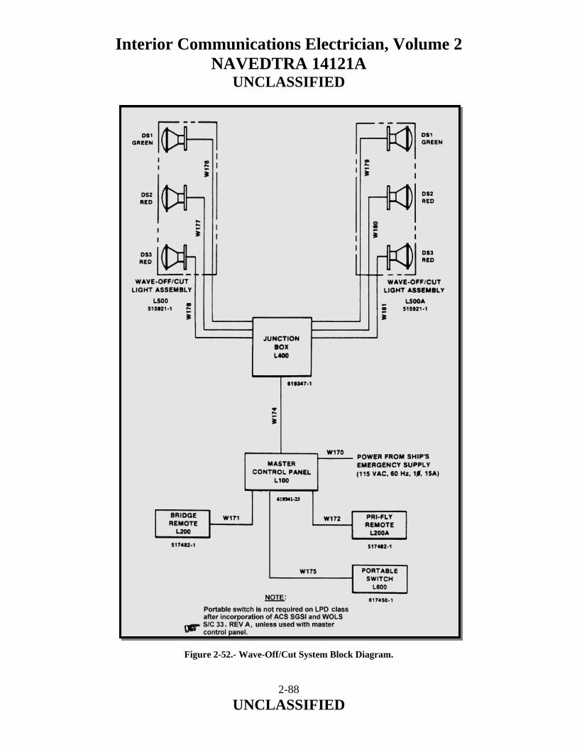
Interior Communications Electrician, Volume 2 NAVEDTRA 14121A
UNCLASSIFIED
Figure 2-52.- Wave-Off/Cut System Block Diagram.
2-88 UNCLASSIFIED

Interior Communications Electrician, Volume 2 NAVEDTRA 14121A
UNCLASSIFIED
The output of transformer T1 goes to the monitor and flasher driver circuit cards and to the system lamps and switches. Diodes CR1 and CR2 make up a full wave rectifier circuit and supply DC power to everything but the circuit cards. The wave-off flasher/driver card receives its input command from the wave-off monitor card and provides variable intensity, a first full brightness flash, continuous flashing, and drive signals for the two SCR’s. The SCR’s continue to be gated and wave-off lights flash as long as the wave-off switch remains in the actuated condition. (Refer to Figure 2-49, Item 8.) The wave-off monitor card receives all the wave-off commands from the various wave-off switches and drives lamps to indicate which switch was pushed. It also drives the panel dimmer, provides a wave-off output to the flasher/driver card, senses voltage across the wave-off lamps, and provides a positive indication of a wave-off at each panel. The cut flasher/driver card receives its input command from the cut monitor card and provides a continuous drive signal for the two SCR’s as long as the cut switch is actuated. Variable intensity is for the cut lamps. The cut monitor card receives all cut commands from the several cut switches and drives lamps to indicate which switch was pushed. It also drives the panel dimmer, provides a cut output to the flasher/driver card, senses voltage across the cut lamps and provides a positive indication of a cut command at each panel. SILICON-CONTROLLED RECTIFIERS (SCR'S) A silicon-controlled rectifier (SCR) is a special diode (see Figure 2-53). Normally it will not pass current in either direction; however, if a positive voltage is applied between its gate and cathode it will turn on and pass current in one direction. Once turned on, an SCR will remain on until the anode-cathode voltage drops to zero or reverses. In the wave-off system the SCR's are connected in inverse parallel configuration. This means they are connected cathode-to-anode. In this way, each diode will pass one half cycle of the sixty-cycle line. An SCR can be checked out of circuit by using a multimeter. This is done by setting the multimeter on its high-ohms scale and measuring the resistance between anode and cathode in both directions. The meter should indicate open. To check the gate circuit, connect the positive meter lead to the anode and the negative to the cathode with the meter set at its XIO scale. The meter should indicate an open. With the leads still attached, connect the gate to the anode. The meter should indicate some value of resistance. These are crude tests and mayor may not work on all units. An in-circuit test is the best test.
2-89 UNCLASSIFIED
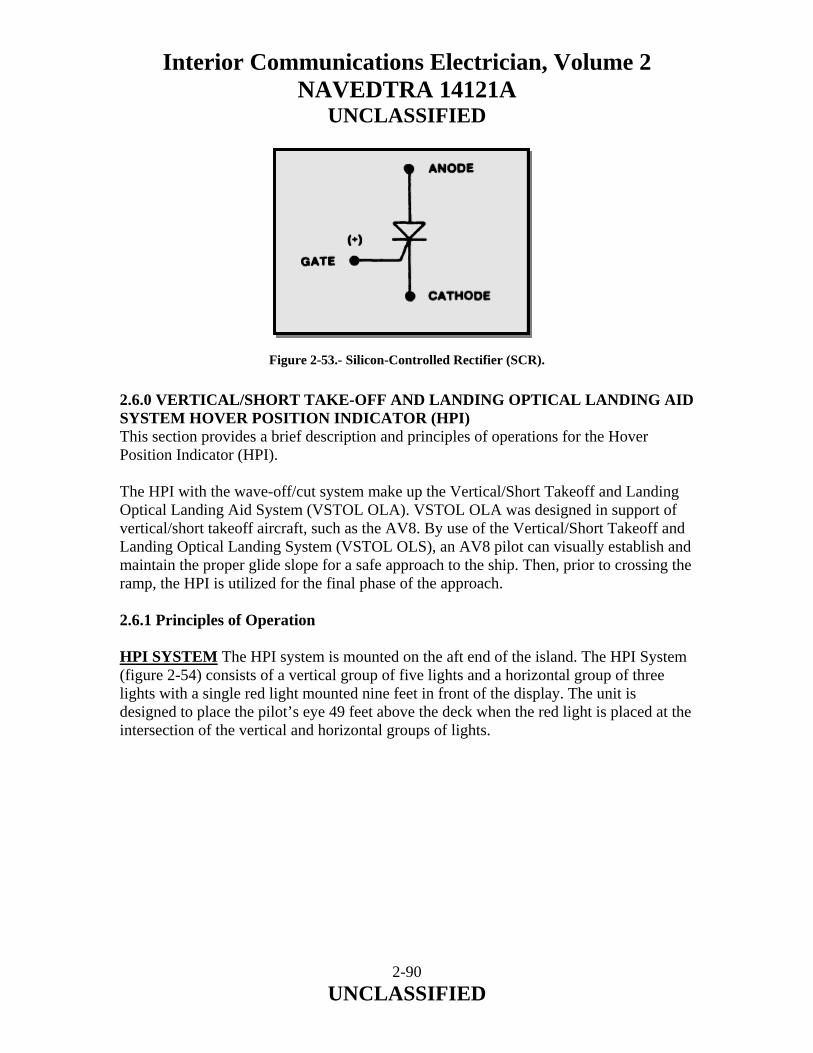
Interior Communications Electrician, Volume 2 NAVEDTRA 14121A
UNCLASSIFIED
Figure 2-53.- Silicon-Controlled Rectifier (SCR). 2.6.0 VERTICAL/SHORT TAKE-OFF AND LANDING OPTICAL LANDING AID SYSTEM HOVER POSITION INDICATOR (HPI) This section provides a brief description and principles of operations for the Hover Position Indicator (HPI). The HPI with the wave-off/cut system make up the Vertical/Short Takeoff and Landing Optical Landing Aid System (VSTOL OLA). VSTOL OLA was designed in support of vertical/short takeoff aircraft, such as the AV8. By use of the Vertical/Short Takeoff and Landing Optical Landing System (VSTOL OLS), an AV8 pilot can visually establish and maintain the proper glide slope for a safe approach to the ship. Then, prior to crossing the ramp, the HPI is utilized for the final phase of the approach. 2.6.1 Principles of Operation HPI SYSTEM The HPI system is mounted on the aft end of the island. The HPI System (figure 2-54) consists of a vertical group of five lights and a horizontal group of three lights with a single red light mounted nine feet in front of the display. The unit is designed to place the pilot’s eye 49 feet above the deck when the red light is placed at the intersection of the vertical and horizontal groups of lights.
2-90 UNCLASSIFIED
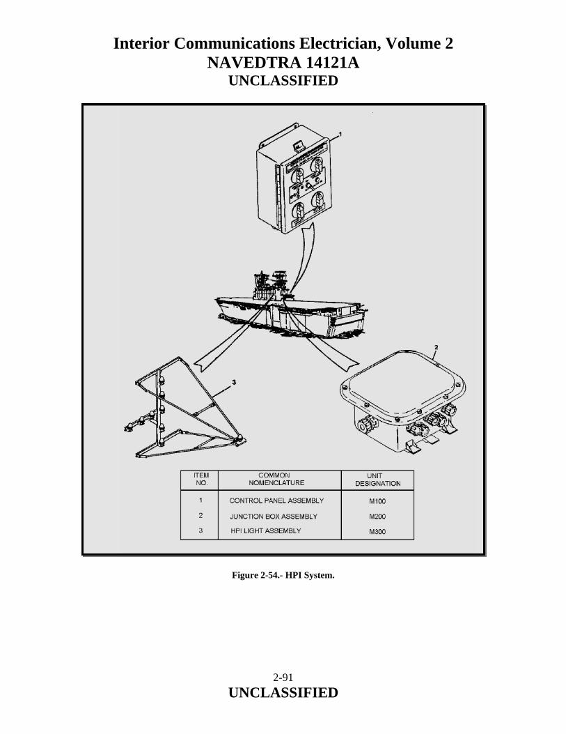
Interior Communications Electrician, Volume 2 NAVEDTRA 14121A
UNCLASSIFIED
Figure 2-54.- HPI System.
2-91 UNCLASSIFIED
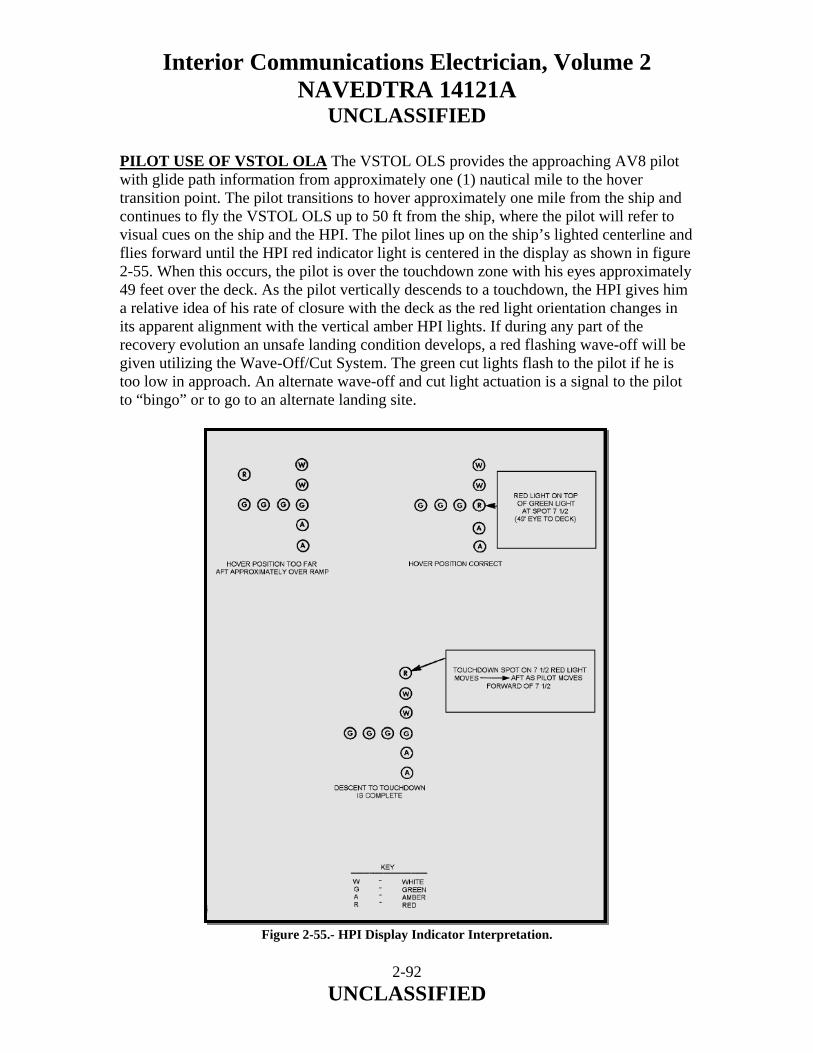
Interior Communications Electrician, Volume 2 NAVEDTRA 14121A
UNCLASSIFIED
PILOT USE OF VSTOL OLA The VSTOL OLS provides the approaching AV8 pilot with glide path information from approximately one (1) nautical mile to the hover transition point. The pilot transitions to hover approximately one mile from the ship and continues to fly the VSTOL OLS up to 50 ft from the ship, where the pilot will refer to visual cues on the ship and the HPI. The pilot lines up on the ship’s lighted centerline and flies forward until the HPI red indicator light is centered in the display as shown in figure 2-55. When this occurs, the pilot is over the touchdown zone with his eyes approximately 49 feet over the deck. As the pilot vertically descends to a touchdown, the HPI gives him a relative idea of his rate of closure with the deck as the red light orientation changes in its apparent alignment with the vertical amber HPI lights. If during any part of the recovery evolution an unsafe landing condition develops, a red flashing wave-off will be given utilizing the Wave-Off/Cut System. The green cut lights flash to the pilot if he is too low in approach. An alternate wave-off and cut light actuation is a signal to the pilot to “bingo” or to go to an alternate landing site.
Figure 2-55.- HPI Display Indicator Interpretation.
2-92 UNCLASSIFIED
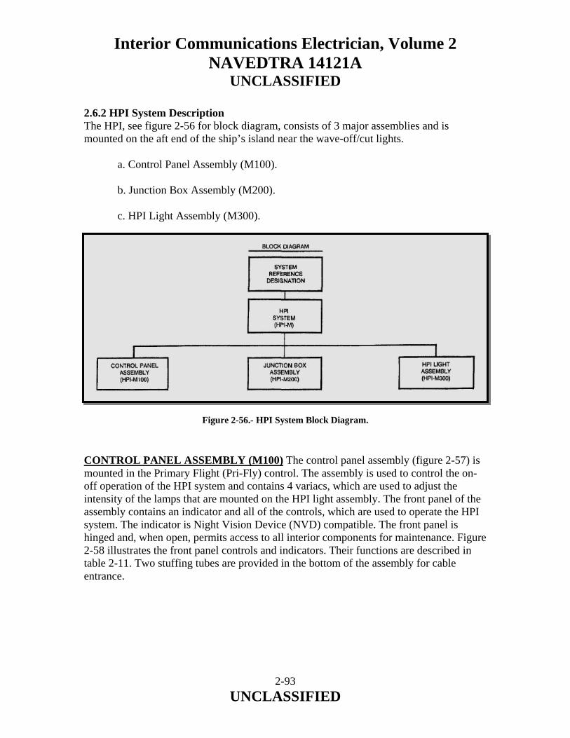
Interior Communications Electrician, Volume 2 NAVEDTRA 14121A
UNCLASSIFIED
2.6.2 HPI System Description The HPI, see figure 2-56 for block diagram, consists of 3 major assemblies and is mounted on the aft end of the ship’s island near the wave-off/cut lights.
a. Control Panel Assembly (M100). b. Junction Box Assembly (M200). c. HPI Light Assembly (M300).
Figure 2-56.- HPI System Block Diagram. CONTROL PANEL ASSEMBLY (M100) The control panel assembly (figure 2-57) is mounted in the Primary Flight (Pri-Fly) control. The assembly is used to control the on-off operation of the HPI system and contains 4 variacs, which are used to adjust the intensity of the lamps that are mounted on the HPI light assembly. The front panel of the assembly contains an indicator and all of the controls, which are used to operate the HPI system. The indicator is Night Vision Device (NVD) compatible. The front panel is hinged and, when open, permits access to all interior components for maintenance. Figure 2-58 illustrates the front panel controls and indicators. Their functions are described in table 2-11. Two stuffing tubes are provided in the bottom of the assembly for cable entrance.
2-93 UNCLASSIFIED
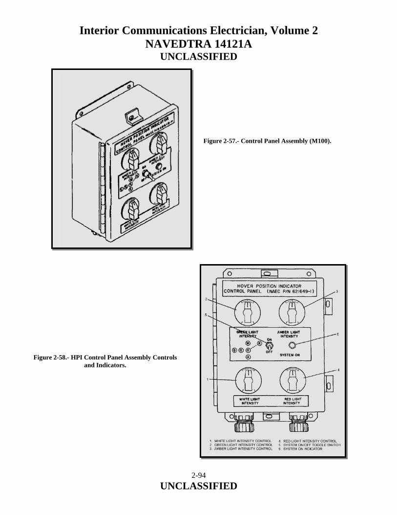
Interior Communications Electrician, Volume 2 NAVEDTRA 14121A
UNCLASSIFIED
Figure 2-57.- Control Panel Assembly (M100).
Figure 2-58.- HPI Control Panel Assembly Controls and Indicators.
2-94 UNCLASSIFIED

Interior Communications Electrician, Volume 2 NAVEDTRA 14121A
UNCLASSIFIED
ITEM NO.
NOMENCLATURE/DEVICE FUNCTION
1 WHITE LIGHT INTENSITY Control Adjust intensity of white lights on HPI light assembly.
2 GREEN LIGHT INTENSITY Control Adjust intensity of green lights on HPI light assembly.
3 AMBER LIGHT INTENSITY Control Adjust intensity of amber lights on HPI light assembly.
4 RED LIGHT INTENSITY Control Adjust intensity of red lights on HPI light assembly.
5 System ON-OFF Toggle Switch Applies 115 VAC, 60 Hz power to HPI system.
6 System ON Indicator Indicates that power has been applied To HPI system.
Table 2-11.- Control Panel Assembly Controls and Indicators.
JUNCTION BOX ASSEMBLY (M200) The Junction Box Assembly (figure 2-59) is mounted just below the HPI light assembly. The assembly is used to interconnect the control panel assembly and the HPI light assembly. Cables enter the assembly by means of 10 stuffing tubes, which are installed in the sides of the box. Access to the interior terminal board is gained by loosing the 10 captive screws, which secure the top of the box assembly. HPI LIGHT ASSEMBLY (M300) The HPI Light Assembly (figure 2-60) consist of a vertical group of 5 light fixture assemblies and a horizontal group of four (4) light fixture assemblies with a single red lamp mounted 9 feet in front of the display. In the vertical group, the two top light fixtures have clear globes and the two lower light fixtures have amber globes. The center light fixture is part of the horizontal group. The horizontal group fixtures have green globes. Lamp is a 115 VAC, 50-watt rough service lamp whose brightness is remotely adjustable from 0-100 percent. The fixtures are supported by a tubular structure and are stiffened by support struts.
2-95 UNCLASSIFIED

Interior Communications Electrician, Volume 2 NAVEDTRA 14121A
UNCLASSIFIED
Figure 2-59.- Junction Box Assembly (M200).
2-96 UNCLASSIFIED

Interior Communications Electrician, Volume 2 NAVEDTRA 14121A
UNCLASSIFIED
Figure 2-60.- HPI Light Assembly (M300).
2-97 UNCLASSIFIED

Interior Communications Electrician, Volume 2 NAVEDTRA 14121A
UNCLASSIFIED
2.7.0 VERTICAL AND SHORT TAKE-OFF AND LANDING OPTICAL LANDING SYSTEM (VSTOL OLS) This section provides organizational level operation and maintenance information for VSTOL OLS. The information includes equipment description and principles of operation. 2.7.1 Equipment Description The VSTOL OLS is a visual landing aid that displays a glideslope path for aircraft approaching a flight deck. The VSTOL OLS guides the aircraft during the landing approach to a position 50 feet above the flight deck for transition to the hover position indicator (HPI). Electronic circuitry compensates for the ship’s yaw and pitch to ensure correct glideslope path. Operational controls are located on the remote control assembly located in the primary flight control station (Pri-Fly). The VSTOL OLS consists of 14 units and accommodates both LHA and LHD ships. 2.7.2 Purpose The VSTOL OLS is a visual landing aid that displays glidepath and trend information to a VSTOL pilot approaching the flight deck. The system presents a display that is visible at a range of 0.8 nm and at a ceiling of 200 feet. The VSTOL OLS guides the aircraft during landing approach to a position 50 feet above the flight deck, where the pilot transitions to the hover position indicator (HPI) system, for hover stop and vertical descent information during the final phase of approach. 2.7.3 System Description The VSTOL OLS display (figures 2-61 and 2-62) consists of lower and upper indicator box assemblies units 11 and 12 mounted vertically between horizontal port side (LHA)/port side (LHD) and starboard side datum arm assemblies units 13 and 14. The system displays an optimal glidepath to the pilot that is compensated for ship's pitch and roll by internal electromechanically stabilized optics. The glidepath basic angle is adjustable from 2.00 to 4.00o in 0.25o increments. With a basic angle of 3o selected, the system can compensate for a maximum roll of ±14o or a maximum pitch of ±3o. At basic angles other than 3o, the system can compensate for a maximum roll of ±12o or a maximum pitch of ±2.25o. The system displays a virtual image (ball) that is dynamically stabilized to compensate for ship's pitch and roll motion. The ball appears aligned between two horizontal datum arm assemblies (figure 2-63) when the pilot is approaching on the optimum glidepath. As the aircraft transitions about the optimum glidepath, the ball will appear to be above or below the datum arm lights if the pilot is approaching high or low relative to the optimum glidepath.
2-98 UNCLASSIFIED
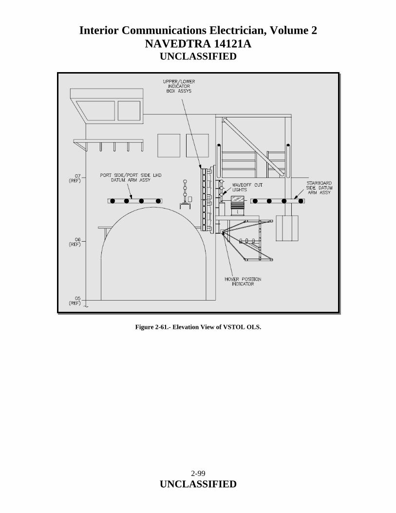
Interior Communications Electrician, Volume 2 NAVEDTRA 14121A
UNCLASSIFIED
Figure 2-61.- Elevation View of VSTOL OLS.
2-99 UNCLASSIFIED

Interior Communications Electrician, Volume 2 NAVEDTRA 14121A
UNCLASSIFIED
Figure 2-62.- Top View of VSTOL OLS.
2-100 UNCLASSIFIED
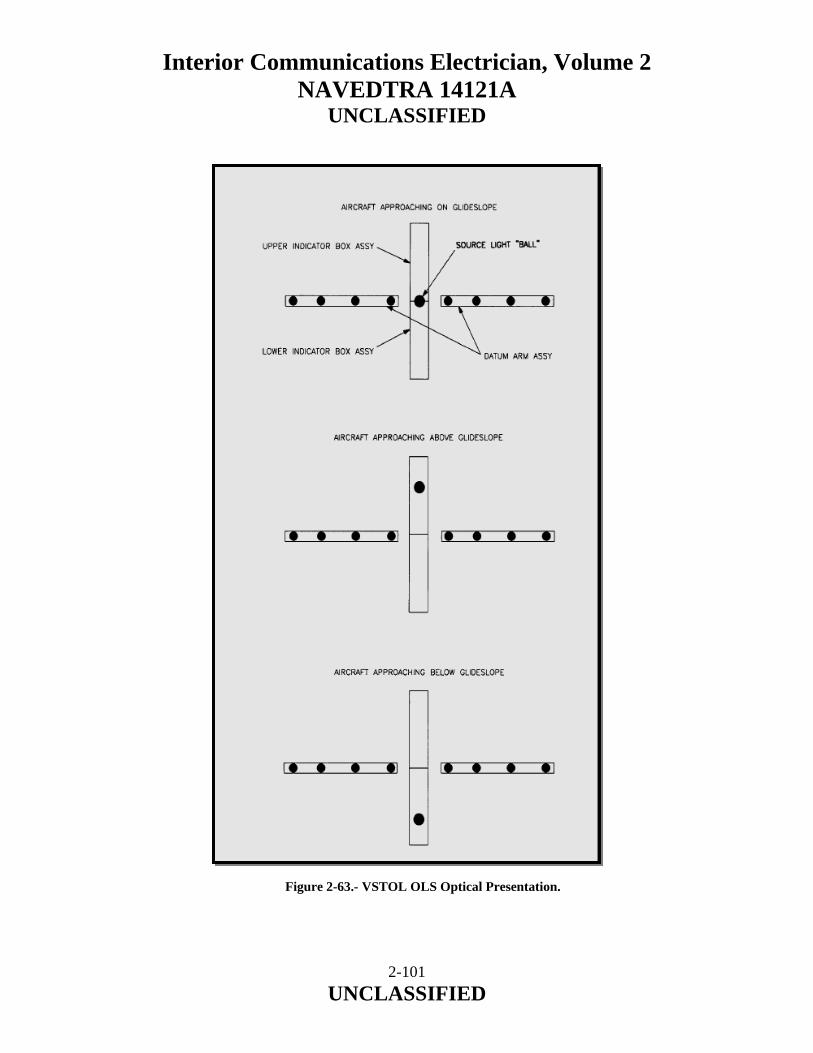
Interior Communications Electrician, Volume 2 NAVEDTRA 14121A
UNCLASSIFIED
Figure 2-63.- VSTOL OLS Optical Presentation.
2-101 UNCLASSIFIED

Interior Communications Electrician, Volume 2 NAVEDTRA 14121A
UNCLASSIFIED
If the pilot's approach is above the optimum glidepath by greater than 1o, the display presents a flashing amber ball. If the approach is below the optimum glidepath by greater than 0.8o, the display presents a constant red ball. If the approach is greater than 1o below the optimum glidepath, the display presents a flashing red ball. Refer to figures 2-64 and 2-65 for system operational characteristics. Figure 2-64.- VSTOL OLS Vertical Coverage. Figure 2-65.- VSTOL OLS Azimuthal Coverage.
2-102 UNCLASSIFIED

Interior Communications Electrician, Volume 2 NAVEDTRA 14121A
UNCLASSIFIED
2.7.4 Major Components Description and Principles of Operation The VSTOL OLS consists of 14 major components (units). The following paragraphs provide descriptions, typical physical locations (figure 2-66), and principles of operation for each unit.
Figure 2-66.- VSTOL OLS Block Diagram Example. POWER CONTROL ENCLOSURE ASSEMBLY Unit 1 controls system power distribution and is typically located adjacent to primary flight control station (Pri-Fly). It contains EMI filtering, 28 Vdc system power supplies, system power control relays, a transient suppression circuit, and circuit-breaker protection for system components and subassemblies. ELECTRONICS ENCLOSURE ASSEMBLY Unit 2 is located adjacent to Pri-Fly and is the signal processing, distribution, and control center for the VSTOL OLS. It consists of a BITE panel assembly for system testing and troubleshooting, circuit breaker panel assembly, 400 Hz inverter for units 11 and 12 synchros, EMI filter, and card cage assembly containing PWAs for the CPU and CPU supporting circuits, variac interface, stabilized optics table (SOT) status interface, synchro-to-digital (S/D) converters, and stepper motor driver circuitry.
2-103 UNCLASSIFIED

Interior Communications Electrician, Volume 2 NAVEDTRA 14121A
UNCLASSIFIED
VARIAC ASSEMBLY Unit 3 is typically located adjacent to Pri-Fly and contains the transformer that controls the brightness of source lights in units 11 and 12 through a computer controlled relay in unit 1. VARIAC ASSEMBLY Unit 4 is typically located adjacent to Pri-Fly and contains the motor driven transformer that controls the brightness of the unit 13 datum lights through a computer-controlled relay in unit 1. VARIAC ASSEMBLY UNIT 5 is typically located adjacent to Pri-Fly and contains the motor driven transformer that controls the brightness of the unit 14 datum lights through a computer-controlled relay in unit 1. REMOTE CONTROL ASSEMBLY Unit 6 contains controls for power on/off and source/datum light intensity. It houses various indicators including system performance lights, lamp out/cell out indicators, stabilization status lights, and troubleshooting status lights. A dimmer controls the intensity of the panel illumination lights. LIGHTING JUNCTION BOX ASSEMBLY Unit 7 is typically located on the aft portion of the island superstructure and is the wiring interface between system display lighting components in units 1, 9, 10, 11, 12, 13, and 14. STABILIZATION JUNCTION BOX ASSEMBLY Unit 8 is typically located on the aft portion of the island superstructure and is the wiring interface between the system stabilization circuit components in units 2, 11, and 12. LOWER SOURCE LIGHT TRANSFORMER ASSEMBLY Unit 9 is typically located on the aft portion of the island superstructure and contains two step-down transformers that convert motor-driven transformer voltages to lamp drive voltages to power the lamps in unit 11. UPPER SOURCE LIGHT TRANSFORMER ASSEMBLY Unit 10 is typically located on the aft portion of the island superstructure and contains two step-down transformers that convert motor-driven transformer voltages to lamp drive voltages to power the lamps in unit 12. LOWER INDICATOR BOX ASSEMBLY Unit 11 is a sealed metal structure attached to a mounting tower located aft of the island superstructure. It contains 10 SOTs, 10 lenses, 2 motor drive assemblies, source light failure interface circuitry, and supporting hardware. Eight light cells have amber lens filters and two light cells have red lens filters.
2-104 UNCLASSIFIED

Interior Communications Electrician, Volume 2 NAVEDTRA 14121A
UNCLASSIFIED
UPPER INDICATOR BOX ASSEMBLY Unit 12 is a sealed metal structure attached to a mounting tower located aft of the island superstructure. It is essentially identical to unit 11, except that the SOT assembly with the flashing solenoid is located in position 10 and all 10 light cells have amber lens filters. PORT SIDE (LHA)/PORT SIDE (LHD) DATUM ARM ASSEMBLY Unit 13 is located on the aft portion of the island superstructure and in combination with unit 14 provides a horizontal reference to units 11 and 12. Unit 13 consists of four equally spaced lamp fixtures fitted with 120 Vac, 300 W medium floodlights. STARBOARD SIDE DATUM ARM ASSEMBLY Unit 14 is located on the aft portion of the island superstructure. It is mounted on the opposite side of units 11 and 12 from unit 13. The operation of unit 14 is identical to that of unit 13. 2.7.5 System Functional Signal Flow The following paragraphs describe the major VSTOL OLS signals shown on figure 2-67.
Figure 2-67.- VSTOL OLS System Functional Block Diagram Example.
2-105 UNCLASSIFIED

Interior Communications Electrician, Volume 2 NAVEDTRA 14121A
UNCLASSIFIED
Wiper Vac Wiper voltages from units 3, 4, and 5 are routed via units 1 and 7 to units 9, 10, 13, and 14 to set intensity of lower source lights, upper source lights, inboard datum lights, and outboard datum lights, respectively. Wiper Vac voltages range from 0 to 115 Vac signals that determine intensity of datum and source lights. The transformer wiper voltages are also supplied via unit 1 to unit 2, where they are converted to dc signals that are monitored by CPU PWA A1A5. 12/24 Vac AC voltages output from units 9 and 10 transformers that determine intensity of units 11 and 12 source lights. Zero to 12 Vac (from transformer center taps) is supplied for normal coverage cells, and 0 to 24 Vac is supplied for extended coverage cells. Levels of these voltages are dependent on unit 3 wiper 0-115 Vac input to units 9 and 10. 115 Vac/28 Vdc These voltages are supplied from unit 1 through unit 7 to units 11 and 12. The 115 Vac is used for heater gaskets and fans. The 28 Vdc is used by 15 Vdc regulator assembly 11/12A12A2 and parallel-to-serial converter PWA 11/12A12A1 inhibit circuit. The voltages are also supplied to unit 2 for use by various PWAs, 5 Vdc power supply PS1 (115 Vac), and 400 Hz inverter PS2 (28 Vdc). 5 Vdc BIT Signals transmitted from unit 6, via unit 1, to unit 2 CPU PWA A1A5, so that CPU PWA A1A5 can monitor output of unit 6 DC/DC converter PS1 and voltage regulator A1A1U1. 28 Vdc Voltage supplied to unit 6 from unit 1 for use by standby indicator light on system control module assembly A4, and DC/DC converter PS1 for generation of unit 6 logic voltage. Power Relay Control Signal applies ground to coil of unit 1 main power control relay K1 when System Power switch in unit 6 is pressed, or when System Power switch in unit 2 is set to ON. 15 Vdc BIT BIT signal transmitted from units 11 and 12 to unit 2 via unit 8. Provides 15 Vdc (logic voltage) regulator status to unit 2 CPU PWA A1A5. Motor F/B 400 Hz ac voltages from drive assembly synchros located in units 11 and 12. Signals provided via unit 8 to unit 2 CPU PWA A1A5 and stepper motor feedback S/D converter A1A2.
2-106 UNCLASSIFIED

Interior Communications Electrician, Volume 2 NAVEDTRA 14121A
UNCLASSIFIED
115 Vac (Phase A, B, C) Three phase, 60 Hz, MIL-STD-1399 compatible ship's power, provided to unit 1 terminal board TB1 for distribution and voltage reduction. Relay Control Signals from unit 2 CPU PWA A1A5 that apply and remove grounds (via unit 2 variac interface PWA A1A1) at low side of unit 1 relay K2, (inboard datum lights) relay K3, and (outboard datum lights) relay K4 coils. Application of ground to low side of relay coil causes related lamps to illuminate. 28 Vdc - Motors DC voltages supplied from unit 1 silicon rectifiers CR1 thru CR4 to activate unit 2 driver PWAs A1A13 thru A1A16 (lower) and A1A18 thru A1A21 (upper). 115 Vac Variac Power Two phases of 115 Vac from unit 1 that are supplied to units 3, 4, and 5 when related unit 1 relay K2, K3, and K4 are energized. Stepper Mtr Inputs Signals generated by unit 2 driver PWAs A1A13 thru A1A16 (lower), and A1A18 thru A1A21 (upper) that determine the step indexing/position of each stepper motor. Each stepper motor has four connections which can energize either one or two phases of each motor. Ref, 2X Roll, 36X Roll, 36X Pitch 400 Hz signals via unit 2 ship gyro S/D converter A1A3, to unit 2 CPU PWA A1A5 that are used to determine correct position for each of the drive shafts located in units 11 and 12. Otbd/Inbd Datum Intensity Control Signals from unit 2 CPU PWA A1A5 to units 4 and 5 control sections. Allows unit 2 CPU PWA A1A5 to increase or decrease variac intensity via variac interface PWA A1A1. Source Intensity Control Signal from unit 2 CPU PWA A1A5 to unit 3 control section. Allows unit 2 CPU PWA A1A5 to increase or decrease variac intensity via variac interface PWA A1A1. Failure Ind BIT status information for various system components. Information is transferred between units 2 and 6 (e.g., switch parity information from unit 6 to unit 2, and lamp out/cell out information from unit 2 to unit 6). Switch Settings Signals provide unit 6 Basic Angle switch, Source Intensity switch, and Datum Intensity switch setting information to unit 2. Basic angle settings range from 2.00 to 4.000 in 0.250increments. Source and datum intensities range from 0 to 10 in increments of 1.
2-107 UNCLASSIFIED
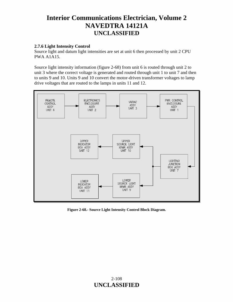
Interior Communications Electrician, Volume 2 NAVEDTRA 14121A
UNCLASSIFIED
2.7.6 Light Intensity Control Source light and datum light intensities are set at unit 6 then processed by unit 2 CPU PWA A1A15. Source light intensity information (figure 2-68) from unit 6 is routed through unit 2 to unit 3 where the correct voltage is generated and routed through unit 1 to unit 7 and then to units 9 and 10. Units 9 and 10 convert the motor-driven transformer voltages to lamp drive voltages that are routed to the lamps in units 11 and 12. Figure 2-68.- Source Light Intensity Control Block Diagram.
2-108 UNCLASSIFIED
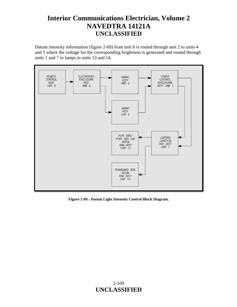
Interior Communications Electrician, Volume 2 NAVEDTRA 14121A
UNCLASSIFIED
Datum intensity information (figure 2-69) from unit 6 is routed through unit 2 to units 4 and 5 where the voltage for the corresponding brightness is generated and routed through units 1 and 7 to lamps in units 13 and 14. Figure 2-69.- Datum Light Intensity Control Block Diagram.
2-109 UNCLASSIFIED
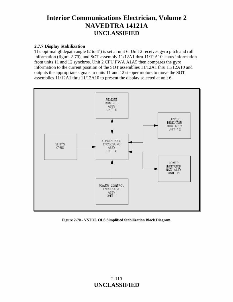
Interior Communications Electrician, Volume 2 NAVEDTRA 14121A
UNCLASSIFIED
2.7.7 Display Stabilization The optimal glidepath angle (2 to 40) is set at unit 6. Unit 2 receives gyro pitch and roll information (figure 2-70), and SOT assembly 11/12A1 thru 11/12A10 status information from units 11 and 12 synchros. Unit 2 CPU PWA A1A5 then compares the gyro information to the current position of the SOT assemblies 11/12A1 thru 11/12A10 and outputs the appropriate signals to units 11 and 12 stepper motors to move the SOT assemblies 11/12A1 thru 11/12A10 to present the display selected at unit 6.
Figure 2-70.- VSTOL OLS Simplified Stabilization Block Diagram.
2-110 UNCLASSIFIED

Interior Communications Electrician, Volume 2 NAVEDTRA 14121A
UNCLASSIFIED
The display is stabilized by moving the internal optical elements in units 11 and 12. Each SOT assembly 11/12A1 thru 11/12A10 is connected to port and starboard vertical shafts. Pitch and roll stabilization is maintained by moving the vertical shafts. Pitch stabilization is attained by moving the port and starboard shafts up or down in unison. Since all SOT assemblies 11/12A1 thru 11/12A10 are rigidly coupled to the shafts, they all move simultaneously. The amount of shaft travel required to stabilize the display is determined by the gyro pitch input to the system. Roll stabilization is performed in the same manner as pitch stabilization, except that the vertical shafts are moved differentially. Therefore, the system can be roll stabilized when there is no pitch motion. 2.8.0 IMPROVED FRESNEL LENS OPTICAL LANDING SYSTEM (IFLOLS) The Improved Fresnel Lens Optical Landing System (IFLOLS) Shipboard MK13 MOD 0 is a visual landing aid system that displays glide path and trend information to a fixed wing pilot approaching the flight deck. The system presents a display that is visible at a range of 1.0 nautical mile. 2.8.1 System Description The Shipboard MK13 IFLOLS deck edge display (figure 2-71) consists of an indicator display assembly (Unit 1) mounted vertically between two vertically oriented wave-off/cut displays (Units 11 and 12), which are flanked by two horizontally mounted datum arms (Units 8 and 9). The system displays an optimal glide path to the pilot that is compensated for ship's pitch, roll and heave by internal electro-mechanically Stabilized Optics Tables (SOTs). The glide path basic angle is adjustable from 3.0° to 4.5° in 0.25° increments. The hook path command is adjustable between 50 feet and 350 feet in 5-foot increments and the aircraft select hook-to-eye setting is adjustable between 12 feet and 22 feet in 0.25-foot increments. Stabilization mode is selectable between line and inertial modes.
2-111 UNCLASSIFIED

Interior Communications Electrician, Volume 2 NAVEDTRA 14121A
UNCLASSIFIED
Figure 2-71.- IFLOLS MK13 Mod 0 Deck Edge Equipment. The system displays a virtual image (ball) that is dynamically stabilized to compensate for ship's pitch, roll and heave motion. The ball appears aligned between two horizontal datum arms (figure 2-72) when the pilot is approaching on the optimum glide path. As the aircraft transitions about the optimum glide path, the ball will appear to be above or below the datum arm lights if the pilot is approaching high or low relative to the optimum glide path. If the pilot's approach is below the glide path by greater than 0.45°, the display presents a flashing red ball (figure 2-72). For all other flight profiles, the system presents a yellow ball. Refer to figure 2-73, figure 2-74 and table 2-12 for system operational characteristics.
2-112 UNCLASSIFIED

Interior Communications Electrician, Volume 2 NAVEDTRA 14121A
UNCLASSIFIED
Figure 2-72.- IFLOLS MK13 and MK14 Optical Presentation.
Figure 2-73.- IFLOLS MK13 Vertical Coverage.
2-113 UNCLASSIFIED
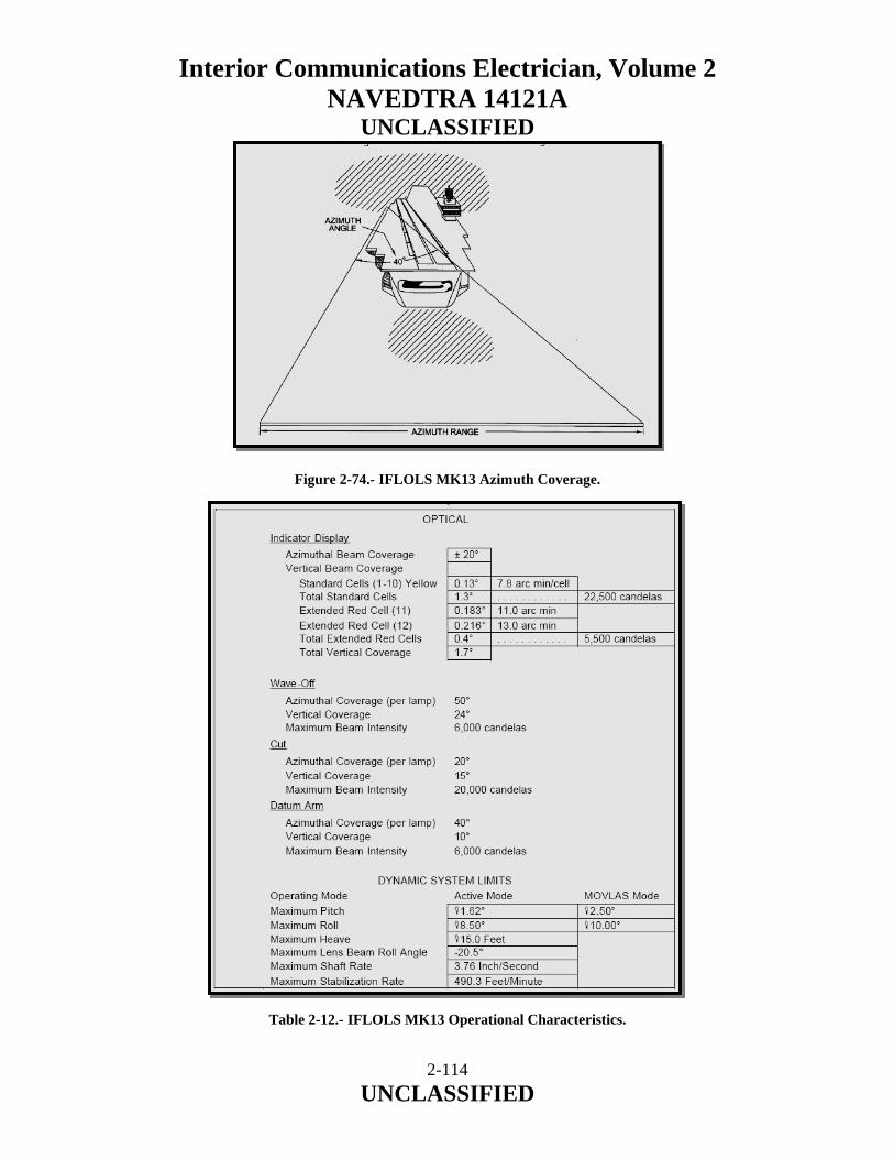
Interior Communications Electrician, Volume 2 NAVEDTRA 14121A
UNCLASSIFIED
2-114 UNCLASSIFIED
Figure 2-74.- IFLOLS MK13 Azimuth Coverage.
Table 2-12.- IFLOLS MK13 Operational Characteristics.
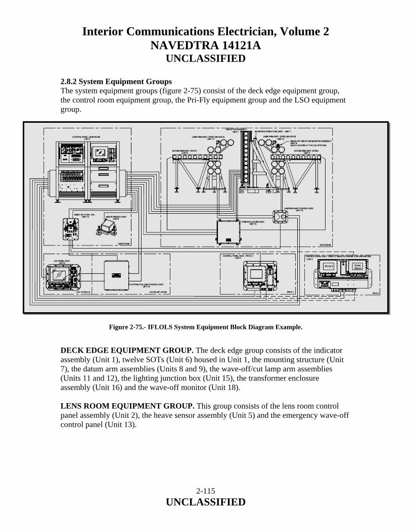
Interior Communications Electrician, Volume 2 NAVEDTRA 14121A
UNCLASSIFIED
2.8.2 System Equipment Groups The system equipment groups (figure 2-75) consist of the deck edge equipment group, the control room equipment group, the Pri-Fly equipment group and the LSO equipment group. Figure 2-75.- IFLOLS System Equipment Block Diagram Example. DECK EDGE EQUIPMENT GROUP. The deck edge group consists of the indicator assembly (Unit 1), twelve SOTs (Unit 6) housed in Unit 1, the mounting structure (Unit 7), the datum arm assemblies (Units 8 and 9), the wave-off/cut lamp arm assemblies (Units 11 and 12), the lighting junction box (Unit 15), the transformer enclosure assembly (Unit 16) and the wave-off monitor (Unit 18). LENS ROOM EQUIPMENT GROUP. This group consists of the lens room control panel assembly (Unit 2), the heave sensor assembly (Unit 5) and the emergency wave-off control panel (Unit 13).
2-115 UNCLASSIFIED

Interior Communications Electrician, Volume 2 NAVEDTRA 14121A
UNCLASSIFIED
PRI-FLY EQUIPMENT GROUP. This group consists of the Pri-Fly control panel assembly (Unit 3) for IFLOLS configurations 3429AS0100-1 and -2 or Pri-Fly/cross check control panel assembly (Unit 3) for IFLOLS configuration 3429AS0100-3. LSO EQUIPMENT GROUP. This group consists of the LSO control panel assembly (Unit 4), the distribution junction box (Unit 10) and the portable switch assembly. 2.8.3 Major Components Shipboard MK 13 Description and Principles of Operation The IFLOLS MK13 MOD 0 consists of 16 separate major components. These components include Units 1 through 18. Units 6 and 14 have been incorporated into Units 1 and 10 respectively. The following paragraphs provide descriptions, typical physical locations and principles of operation for each unit. Refer to figures 2-76 and 2-77 for IFLOLS system electrical interconnect and table 2-13 for physical characteristics of units. Figure 2-76.- IFLOLS MK13 System Interconnect Block Diagram Example.
2-116 UNCLASSIFIED

Interior Communications Electrician, Volume 2 NAVEDTRA 14121A
UNCLASSIFIED
Figure 2-77.- IFLOLS MK13 System Interconnect Block Diagram with Service Change #3
Example.
2-117 UNCLASSIFIED
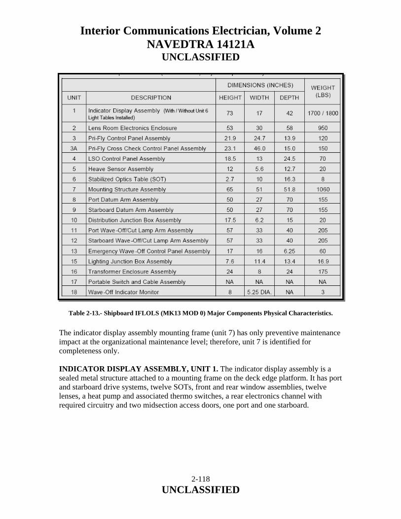
Interior Communications Electrician, Volume 2 NAVEDTRA 14121A
UNCLASSIFIED
Table 2-13.- Shipboard IFLOLS (MK13 MOD 0) Major Components Physical Characteristics. The indicator display assembly mounting frame (unit 7) has only preventive maintenance impact at the organizational maintenance level; therefore, unit 7 is identified for completeness only. INDICATOR DISPLAY ASSEMBLY, UNIT 1. The indicator display assembly is a sealed metal structure attached to a mounting frame on the deck edge platform. It has port and starboard drive systems, twelve SOTs, front and rear window assemblies, twelve lenses, a heat pump and associated thermo switches, a rear electronics channel with required circuitry and two midsection access doors, one port and one starboard.
2-118 UNCLASSIFIED
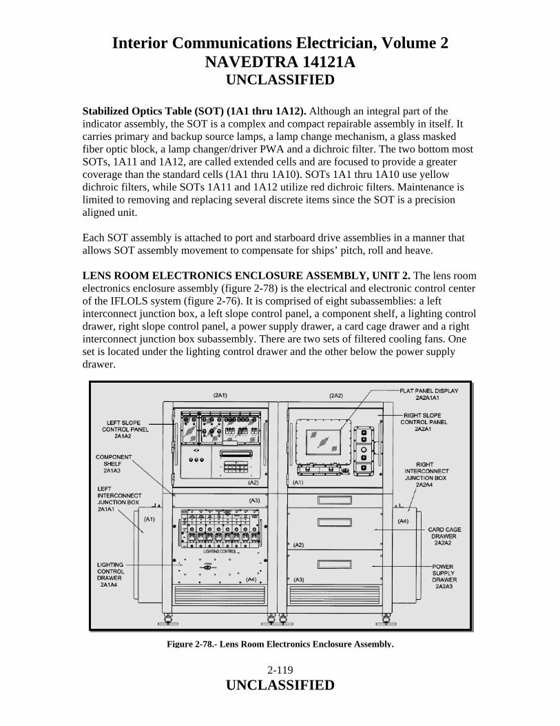
Interior Communications Electrician, Volume 2 NAVEDTRA 14121A
UNCLASSIFIED
Stabilized Optics Table (SOT) (1A1 thru 1A12). Although an integral part of the indicator assembly, the SOT is a complex and compact repairable assembly in itself. It carries primary and backup source lamps, a lamp change mechanism, a glass masked fiber optic block, a lamp changer/driver PWA and a dichroic filter. The two bottom most SOTs, 1A11 and 1A12, are called extended cells and are focused to provide a greater coverage than the standard cells (1A1 thru 1A10). SOTs 1A1 thru 1A10 use yellow dichroic filters, while SOTs 1A11 and 1A12 utilize red dichroic filters. Maintenance is limited to removing and replacing several discrete items since the SOT is a precision aligned unit. Each SOT assembly is attached to port and starboard drive assemblies in a manner that allows SOT assembly movement to compensate for ships’ pitch, roll and heave. LENS ROOM ELECTRONICS ENCLOSURE ASSEMBLY, UNIT 2. The lens room electronics enclosure assembly (figure 2-78) is the electrical and electronic control center of the IFLOLS system (figure 2-76). It is comprised of eight subassemblies: a left interconnect junction box, a left slope control panel, a component shelf, a lighting control drawer, right slope control panel, a power supply drawer, a card cage drawer and a right interconnect junction box subassembly. There are two sets of filtered cooling fans. One set is located under the lighting control drawer and the other below the power supply drawer.
Figure 2-78.- Lens Room Electronics Enclosure Assembly.
2-119 UNCLASSIFIED

Interior Communications Electrician, Volume 2 NAVEDTRA 14121A
UNCLASSIFIED
Left Interconnect Junction Box Subassembly (2A1A1). The junction box (figure 2-78) contains four terminal boards that provide interconnection points for all system power and lighting functions. Left Slope Control Panel Subassembly (2A1A2). The left slope control panel (figures 2-78 and 2-79) contains five subassemblies: three are power indicators and circuit breakers for the system/subsystems, one provides fuse protection for the transient suppression network and the fifth component is the BITE panel with LED readout and lamp indicators.
Figure 2-79.- Left Slope Control Panel Subassembly.
2-120 UNCLASSIFIED

Interior Communications Electrician, Volume 2 NAVEDTRA 14121A
UNCLASSIFIED
Emergency Wave-Off Power Circuit Breakers and Power Indicators (2A1A2A1). The IFLOLS system utilizes power from the ship’s emergency wave-off system. This external power ensures the wave-off location data will be sent to all the external interface systems when the IFLOLS system is “OFF”. As a result, this circuit breaker should only be turned “OFF” during maintenance actions when the IFLOLS and emergency wave-off systems are not needed for flight-ops. The power indicator is lit when the breaker is activated and power is present. Component Shelf Subassembly (2A1A3). The entire area behind the left slope control panel subassembly (figure 2-78 and 2-80) is considered part of this subassembly; however, not all components are mounted on the shelf itself. The subassembly is made up of; two variacs, a fiber optic Ethernet hub, an EMI filter two relays and six terminal boards. Figure 2-80.- Component Shelf Assembly. Lighting Control Drawer Subassembly (2A1A4). The lighting control drawer (figures 2-78 and 2-81) consists of two power supplies, three variacs, twelve terminal boards and four PWAs. The primary purposes of the lighting control drawer are to provide power and intensity control for the lighting for all five deck edge display units, provide communication with the system main CPU and to process and display deck edge lighting display faults. The exterior face of the lighting control drawer provides additional system status information through the use of indicator lamps, circuit breakers and fuses.
2-121 UNCLASSIFIED

Interior Communications Electrician, Volume 2 NAVEDTRA 14121A
UNCLASSIFIED
Figure 2-81.- Lighting Control Drawer Front Panel. Right Slope Control Panel Subassembly (2A2A1). The right slope control panel (figures 2-78 and 2-82) consists of a control panel on which are mounted three subassemblies: a flat panel display, a display control module and an intensity control module. The shroud base subassembly, which forms the base of this subassembly, provides a place on which to mount two power supplies, a fiber optic transceiver, a relay and its socket, a diode, a resistor and four terminal boards.
2-122 UNCLASSIFIED

Interior Communications Electrician, Volume 2 NAVEDTRA 14121A
UNCLASSIFIED
Figure 2-82.- Lens Room Right Slope Subassembly. Flat Panel Display Assembly (2A2A1A1). This assembly (figure 2-82) provides the lens room operator with seven (7) visual display/touch screens: the system MAIN screen, LIGHTING screen, STABILIZATION screen, NON-STD (standard) screen, MODE/STATUS screen, CALIBRATION screen and POLE CHECK screen. The flat panel will display all BITE error conditions in the status bar area of all screens with the exception of the calibration screen. Refer to WP 008 00, table 1 for a complete listing of BITE panel error messages. Lens Room Main Screen Display. This screen (figure 2-83) has five major elements. The status bar, which is common to all lens room screens with the exception of the CALIBRATION and POLE CHECK screens, provides fourteen discrete data elements: Aircraft (A/C) type, Hook-to-Eye (H/E) distance, Basic Angle (BA) setting, which wire is optimal and its distance from the round down, system stabilization mode, system status, failure mode, where certain system failures will be indicated, Air Officer (A/O) interlock status, whether a Hook-to-Ramp (H/R) warning has been issued, status and frequency of the system low cell flash capability, whether wave-off has been initiated, whether cut has been initiated and whether the barricade is raised.
2-123 UNCLASSIFIED
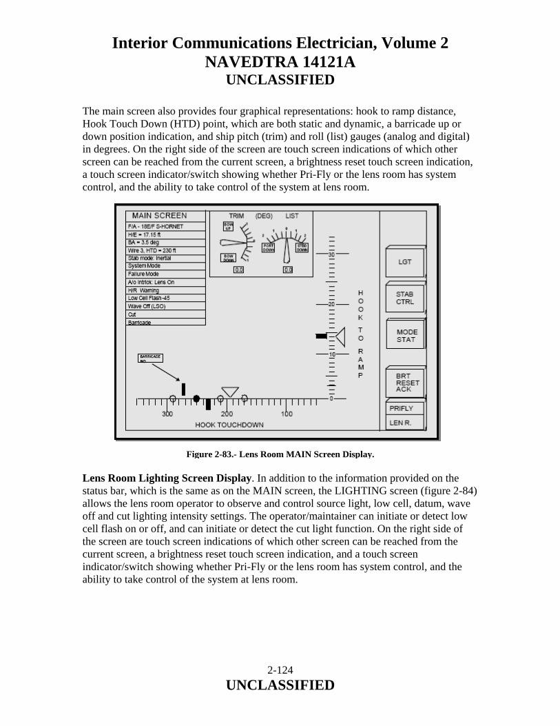
Interior Communications Electrician, Volume 2 NAVEDTRA 14121A
UNCLASSIFIED
The main screen also provides four graphical representations: hook to ramp distance, Hook Touch Down (HTD) point, which are both static and dynamic, a barricade up or down position indication, and ship pitch (trim) and roll (list) gauges (analog and digital) in degrees. On the right side of the screen are touch screen indications of which other screen can be reached from the current screen, a brightness reset touch screen indication, a touch screen indicator/switch showing whether Pri-Fly or the lens room has system control, and the ability to take control of the system at lens room. Figure 2-83.- Lens Room MAIN Screen Display. Lens Room Lighting Screen Display. In addition to the information provided on the status bar, which is the same as on the MAIN screen, the LIGHTING screen (figure 2-84) allows the lens room operator to observe and control source light, low cell, datum, wave off and cut lighting intensity settings. The operator/maintainer can initiate or detect low cell flash on or off, and can initiate or detect the cut light function. On the right side of the screen are touch screen indications of which other screen can be reached from the current screen, a brightness reset touch screen indication, and a touch screen indicator/switch showing whether Pri-Fly or the lens room has system control, and the ability to take control of the system at lens room.
2-124 UNCLASSIFIED
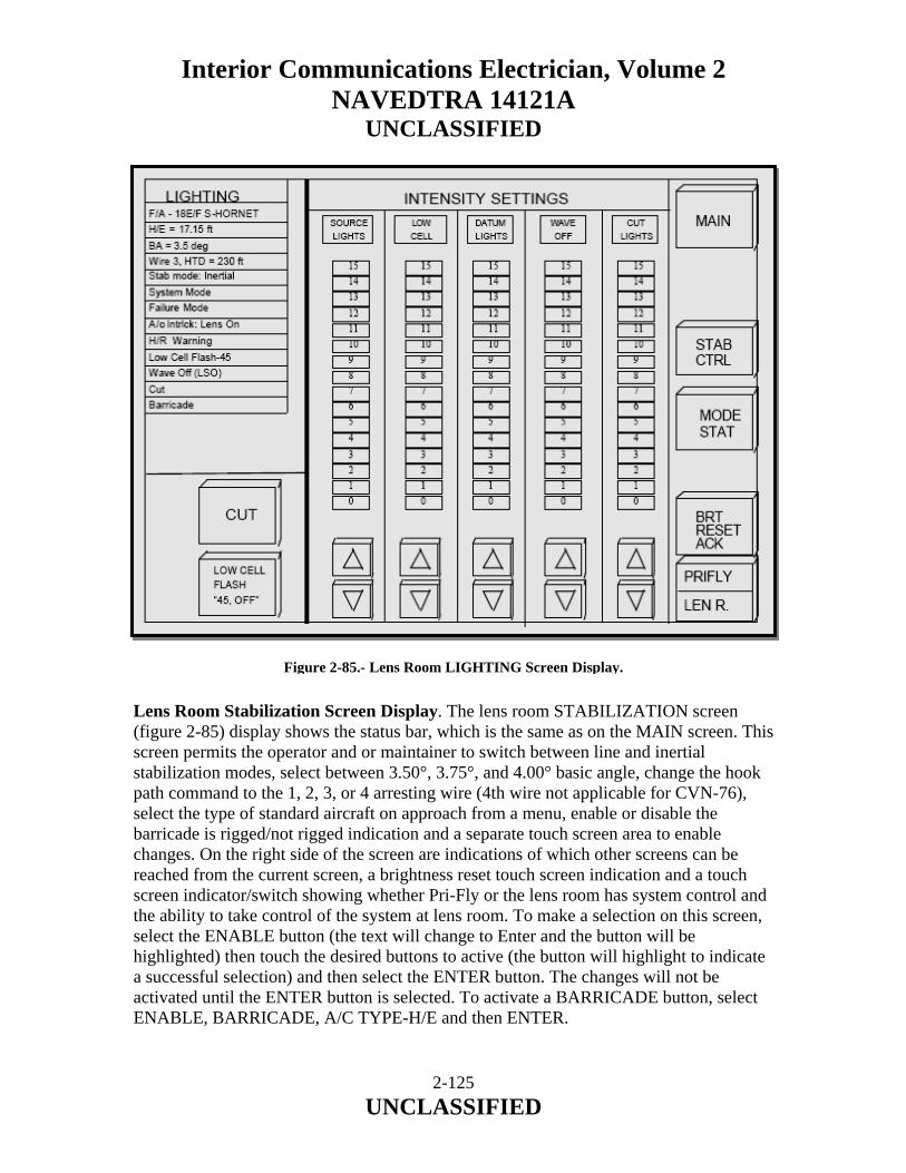
Interior Communications Electrician, Volume 2 NAVEDTRA 14121A
UNCLASSIFIED
Figure 2-85.- Lens Room LIGHTING Screen Display. Lens Room Stabilization Screen Display. The lens room STABILIZATION screen (figure 2-85) display shows the status bar, which is the same as on the MAIN screen. This screen permits the operator and or maintainer to switch between line and inertial stabilization modes, select between 3.50°, 3.75°, and 4.00° basic angle, change the hook path command to the 1, 2, 3, or 4 arresting wire (4th wire not applicable for CVN-76), select the type of standard aircraft on approach from a menu, enable or disable the barricade is rigged/not rigged indication and a separate touch screen area to enable changes. On the right side of the screen are indications of which other screens can be reached from the current screen, a brightness reset touch screen indication and a touch screen indicator/switch showing whether Pri-Fly or the lens room has system control and the ability to take control of the system at lens room. To make a selection on this screen, select the ENABLE button (the text will change to Enter and the button will be highlighted) then touch the desired buttons to active (the button will highlight to indicate a successful selection) and then select the ENTER button. The changes will not be activated until the ENTER button is selected. To activate a BARRICADE button, select ENABLE, BARRICADE, A/C TYPE-H/E and then ENTER.
2-125 UNCLASSIFIED
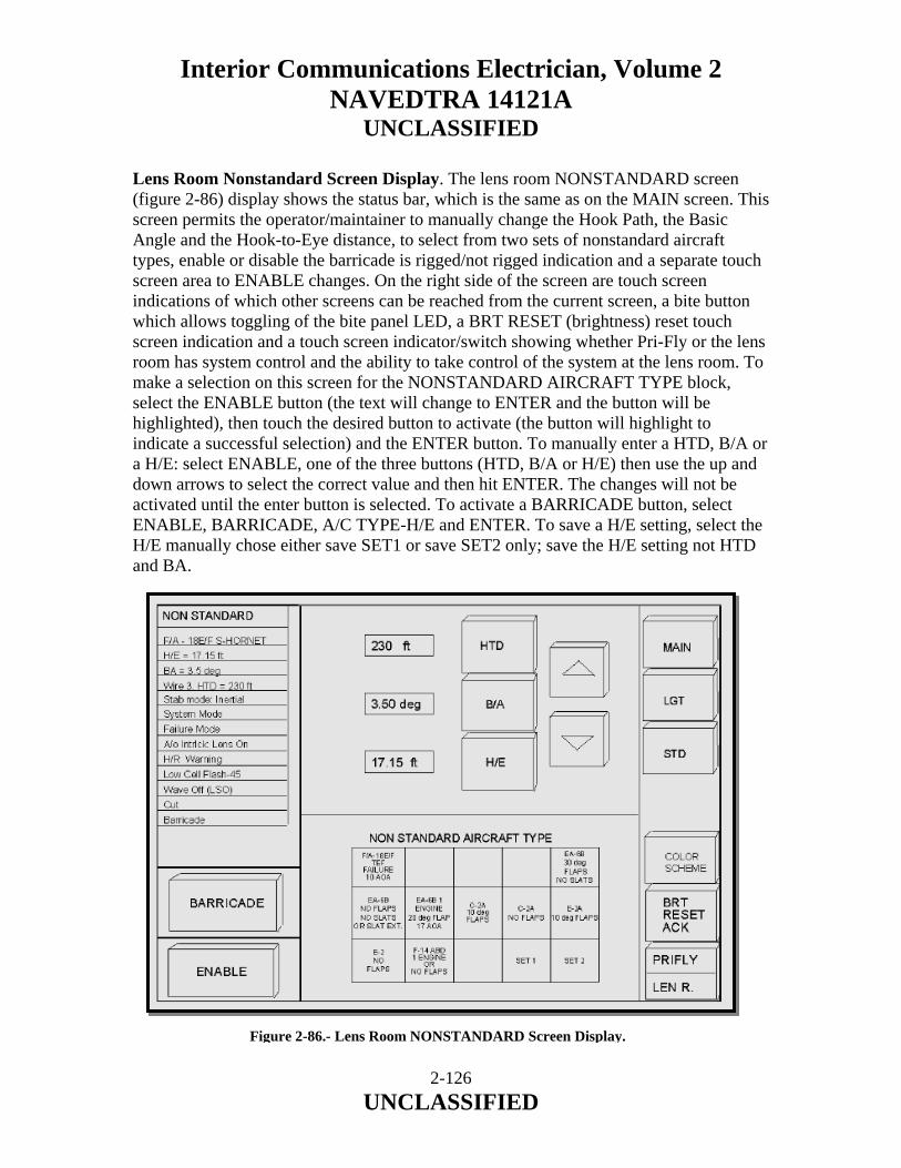
Interior Communications Electrician, Volume 2 NAVEDTRA 14121A
UNCLASSIFIED
Lens Room Nonstandard Screen Display. The lens room NONSTANDARD screen (figure 2-86) display shows the status bar, which is the same as on the MAIN screen. This screen permits the operator/maintainer to manually change the Hook Path, the Basic Angle and the Hook-to-Eye distance, to select from two sets of nonstandard aircraft types, enable or disable the barricade is rigged/not rigged indication and a separate touch screen area to ENABLE changes. On the right side of the screen are touch screen indications of which other screens can be reached from the current screen, a bite button which allows toggling of the bite panel LED, a BRT RESET (brightness) reset touch screen indication and a touch screen indicator/switch showing whether Pri-Fly or the lens room has system control and the ability to take control of the system at the lens room. To make a selection on this screen for the NONSTANDARD AIRCRAFT TYPE block, select the ENABLE button (the text will change to ENTER and the button will be highlighted), then touch the desired button to activate (the button will highlight to indicate a successful selection) and the ENTER button. To manually enter a HTD, B/A or a H/E: select ENABLE, one of the three buttons (HTD, B/A or H/E) then use the up and down arrows to select the correct value and then hit ENTER. The changes will not be activated until the enter button is selected. To activate a BARRICADE button, select ENABLE, BARRICADE, A/C TYPE-H/E and ENTER. To save a H/E setting, select the H/E manually chose either save SET1 or save SET2 only; save the H/E setting not HTD and BA.
Figure 2-86.- Lens Room NONSTANDARD Screen Display.
2-126 UNCLASSIFIED
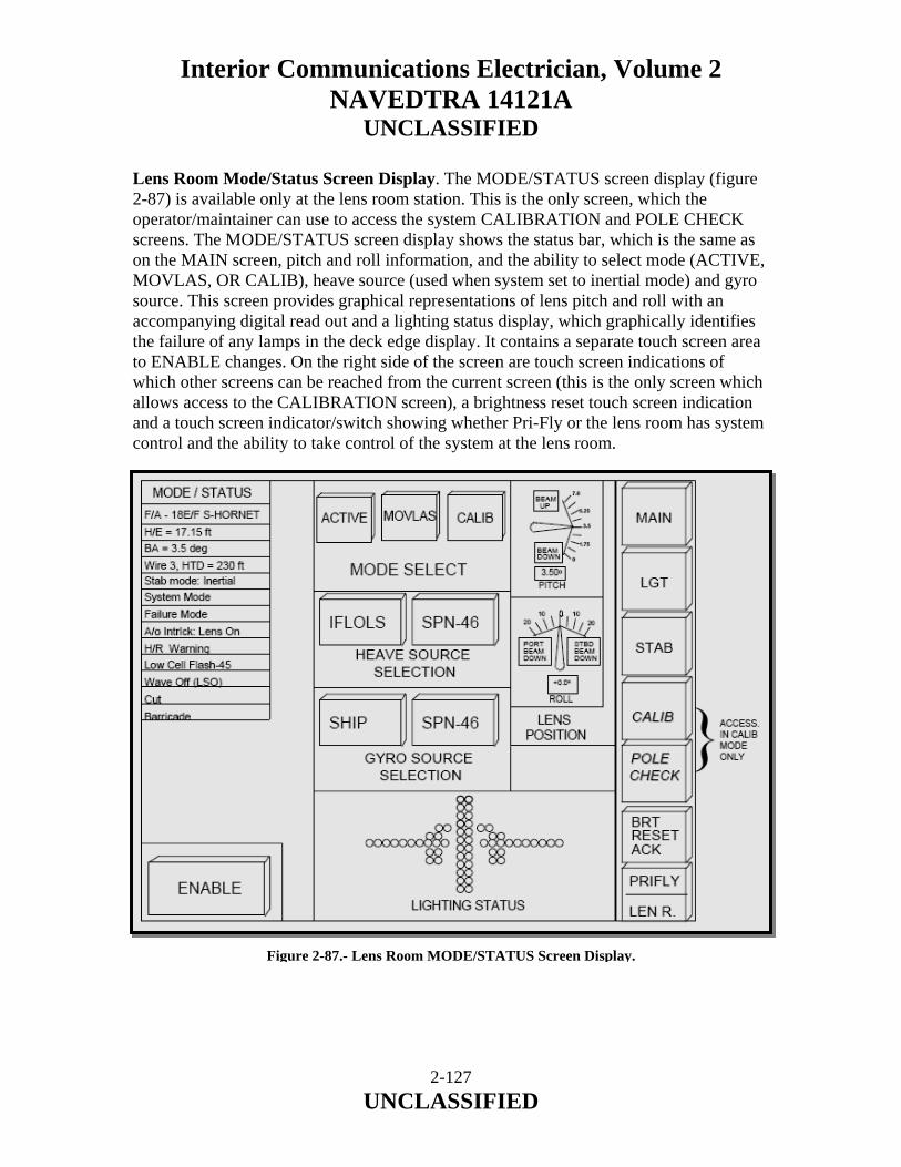
Interior Communications Electrician, Volume 2 NAVEDTRA 14121A
UNCLASSIFIED
Lens Room Mode/Status Screen Display. The MODE/STATUS screen display (figure 2-87) is available only at the lens room station. This is the only screen, which the operator/maintainer can use to access the system CALIBRATION and POLE CHECK screens. The MODE/STATUS screen display shows the status bar, which is the same as on the MAIN screen, pitch and roll information, and the ability to select mode (ACTIVE, MOVLAS, OR CALIB), heave source (used when system set to inertial mode) and gyro source. This screen provides graphical representations of lens pitch and roll with an accompanying digital read out and a lighting status display, which graphically identifies the failure of any lamps in the deck edge display. It contains a separate touch screen area to ENABLE changes. On the right side of the screen are touch screen indications of which other screens can be reached from the current screen (this is the only screen which allows access to the CALIBRATION screen), a brightness reset touch screen indication and a touch screen indicator/switch showing whether Pri-Fly or the lens room has system control and the ability to take control of the system at the lens room. Figure 2-87.- Lens Room MODE/STATUS Screen Display.
2-127 UNCLASSIFIED
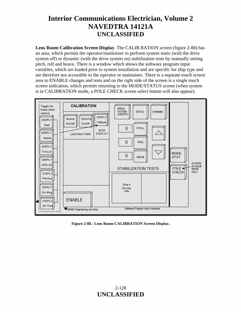
Interior Communications Electrician, Volume 2 NAVEDTRA 14121A
UNCLASSIFIED
Lens Room Calibration Screen Display. The CALIB RATION screen (figure 2-88) has an area, which permits the operator/maintainer to perform system static (with the drive system off) or dynamic (with the drive system on) stabilization tests by manually setting pitch, roll and heave. There is a window which shows the software program input variables, which are loaded prior to system installation and are specific for ship type and are therefore not accessible to the operator or maintainer. There is a separate touch screen area to ENABLE changes and tests and on the right side of the screen is a single touch screen indication, which permits returning to the MODE/STATUS screen (when system is in CALIBRATION mode, a POLE CHECK screen select button will also appear). Figure 2-88.- Lens Room CALIBRATION Screen Display.
2-128 UNCLASSIFIED
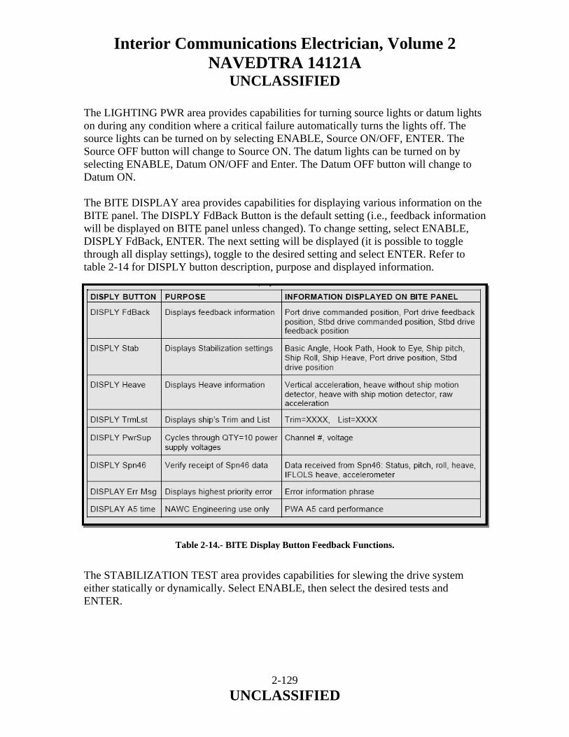
Interior Communications Electrician, Volume 2 NAVEDTRA 14121A
UNCLASSIFIED
The LIGHTING PWR area provides capabilities for turning source lights or datum lights on during any condition where a critical failure automatically turns the lights off. The source lights can be turned on by selecting ENABLE, Source ON/OFF, ENTER. The Source OFF button will change to Source ON. The datum lights can be turned on by selecting ENABLE, Datum ON/OFF and Enter. The Datum OFF button will change to Datum ON. The BITE DISPLAY area provides capabilities for displaying various information on the BITE panel. The DISPLY FdBack Button is the default setting (i.e., feedback information will be displayed on BITE panel unless changed). To change setting, select ENABLE, DISPLY FdBack, ENTER. The next setting will be displayed (it is possible to toggle through all display settings), toggle to the desired setting and select ENTER. Refer to table 2-14 for DISPLY button description, purpose and displayed information.
Table 2-14.- BITE Display Button Feedback Functions. The STABILIZATION TEST area provides capabilities for slewing the drive system either statically or dynamically. Select ENABLE, then select the desired tests and ENTER.
2-129 UNCLASSIFIED
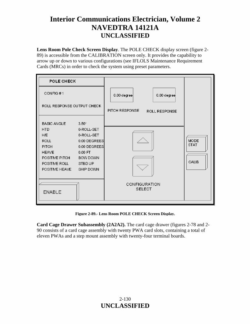
Interior Communications Electrician, Volume 2 NAVEDTRA 14121A
UNCLASSIFIED
Lens Room Pole Check Screen Display. The POLE CHECK display screen (figure 2-89) is accessible from the CALIBRATION screen only. It provides the capability to arrow up or down to various configurations (see IFLOLS Maintenance Requirement Cards (MRCs) in order to check the system using preset parameters. Figure 2-89.- Lens Room POLE CHECK Screen Display. Card Cage Drawer Subassembly (2A2A2). The card cage drawer (figures 2-78 and 2-90 consists of a card cage assembly with twenty PWA card slots, containing a total of eleven PWAs and a step mount assembly with twenty-four terminal boards.
2-130 UNCLASSIFIED

Interior Communications Electrician, Volume 2 NAVEDTRA 14121A
UNCLASSIFIED
Figure 2-90.- Card Cage Drawer Assembly. Power Supply Drawer Subassembly (2A2A3). The power supply drawer (figures 2-78 and 2-91) consists of five power supplies, two motor drivers, eight terminal boards and associated hardware. The primary purpose of the power supply drawer is to provide power to the card cage, motors and emergency wave-off circuits.
Figure 2-91.- Power Supply Drawer Assembly.
2-131 UNCLASSIFIED

Interior Communications Electrician, Volume 2 NAVEDTRA 14121A
UNCLASSIFIED
Right Interconnect Junction Box (2A2A4). The right interconnect junction box (figure 2-78) contains twenty-four terminal boards which provide power and signal interconnection points for all system functions other than lighting and system power, which are handled by the left interconnect junction box. The assemblies primary purpose is to provide a junction point for IFLOLS system stabilization and communication signals, but it also provides wave-off and cut signals to the Integrated Launch and Recovery Television Surveillance (ILARTS) system and pitch, roll and Basic Angle (BA) data to the Electronic Cross Hair Stabilization System (ECSS). PRI-FLY CONTROL PANEL ASSEMBLY, UNIT 3. The Pri-Fly control panel assembly (figure 2-92) provides specific system information and the ability to make changes in various system settings as described below. The unit is bulkhead mounted and consists of a flat panel display module, a display control module, an intensity control module and a shroud base subassembly. Unit 3 control panel also acts as a connection point for the air officer’s “WAVE-OFF” switch and “LIGHTING INTERLOCK” switch (also known as the “LENS OFF/LENS ON“ switch) located in the air officer’s center control console. IFLOLS senses closure of both switches and provides illumination power for these switches. Flat Panel Display Assembly (3A1A1). The Flat Panel Display assembly (figure 2-92) provides specific system information with four visual display/touch screens: the MAIN screen display, the LIGHTING screens display, the STABILIZATION screen display and the NON-STD (standard) screen display. The flat panel will display all BITE error conditions in the status bar area of all screens. NOTE All screen displays for the Pri-Fly control panel are comparable to those previously described in the sections for the Lens Room screen displays. There are subtle differences, such as the NONSTANDARD screen display (Figure 2-93) in Pri-Fly includes a MOVLAS function that is not included in the Lens Room. The Pri-Fly control panel does not include screen displays for the MODE/STATUS, CALIBRATION and POLE CHECK screen displays.
2-132 UNCLASSIFIED
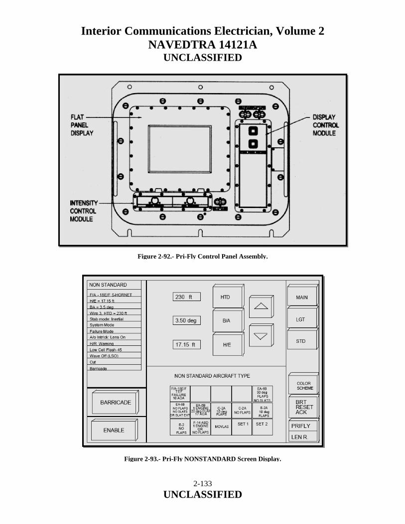
Interior Communications Electrician, Volume 2 NAVEDTRA 14121A
UNCLASSIFIED
Figure 2-92.- Pri-Fly Control Panel Assembly. Figure 2-93.- Pri-Fly NONSTANDARD Screen Display.
2-133 UNCLASSIFIED

Interior Communications Electrician, Volume 2 NAVEDTRA 14121A
UNCLASSIFIED
Pri-Fly Nonstandard Screen Display. The Pri-Fly NONSTANDARD screen display (figure 2-93) shows the status bar, which is the same as on the MAIN screen. This screen permits the air boss to manually change the hook path, the basic angle and the hook to eye distance, to select nonstandard aircraft types, to save and set two nonstandard configurations and to enable or disable the barricade. Additionally, a separate touch screen area to ENABLE changes. On the right side of the screen are touch screen indications of which other screens can be reached from the current screen, a color scheme button for setting the display to white or red graphics, a BRT RESET (brightness) reset touch screen indication, and a touch screen indicator/switch showing whether Pri-Fly or the lens room has system control, and the ability to take control of the system at Pri-Fly. To make a selection on this screen for the NONSTANDARD AIRCRAFT TYPE, select ENABLE button (the text will change to ENTER and the button will be highlighted), then touch the desired button to activate (the button will highlight to indicate a successful selection) and then select ENTER button. To manually enter a HTD, B/A or a H/E, select ENABLE, one of the three buttons (HTD, B/A, or H/E), use the up and down arrows to select the correct value then hit ENTER. The changes will not be activated until the ENTER button is selected. To activate a BARRICADE button select ENABLE, BARRICADE, A/C TYPE-H/E and then ENTER. To save a H/E setting, select the H/E manually, choose either save SET1 or save SET2 then select ENTER. The saved setting can now be accessed using the button that it was saved under. LSO CONTROL PANEL ASSEMBLY, UNIT 4. The LSO control panel assembly (figure 2-94) located at the LSO workstation provides the LSO with specific information concerning system and system interface status. The LSO does not have touch screen capability at the control panel since the flat panel has a fixed "weather cover" mounted over it. This cover extends to cover the intensity controls but is hinged and latched for easy access to those controls. The LSO has the ability to change the intensity settings for the system deck edge display on the lighting screen display by switches located on the display control module. In an emergency situation, the LSO can initiate wave-off or cut from this unit. The assembly consists of a flat panel display, display control module, intensity control module and a shroud base subassembly. (If Service change 7 - Landing Signaling Officer Display (LSOD) is incorporated, omit LSO control Panel Assembly part number 3429AS0400- 2) Flat Panel Display Assembly (4A1A1). This assembly (figure 2-94) provides the LSO with two unique visual display screens: a main screen and a lighting screen. The two screens are modified versions of the system MAIN screen and system LIGHTING screen as found at the lens room and Pri-Fly control panels.
2-134 UNCLASSIFIED

Interior Communications Electrician, Volume 2 NAVEDTRA 14121A
UNCLASSIFIED
Figure 2-94.- LSO Control Panel. LSO Main Screen Display. The LSO main screen display (figure 2-95) graphically represents a hook-to-ramp meter and a Hook Touch Down (HTD) meter. Both meters display dynamic and static information. Additionally, a barricade indicator and targeted wire information are displayed. Across the screen in larger letters is displayed the A/C type, H/E, BA, "FAILURE" message and wave-off indication. This screen also provides two lines of text, which are only displayed under certain conditions; line four will indicate a major system FAILURE and the fifth line will indicate that WAVE-OFF has been initiated.
2-135 UNCLASSIFIED

Interior Communications Electrician, Volume 2 NAVEDTRA 14121A
UNCLASSIFIED
Figure 2-95.- LSO MAIN Screen Display. LSO Lighting Screen Display. The LSO lighting screen display (figure 2-96) has three areas providing information: the status bar, which has thirteen discrete data elements: aircraft (A/C) type, Hook-to-Eye (H/E) distance, Basic Angle (BA) setting, which wire is optimal and its distance from the round down, system stabilization mode, system status, FAILURE MODE, where system failures will be indicated, Air Officer (A/O) interlock status, whether a Hook-to-Ramp (H/R) warning has been issued, status and frequency of the system low cell flash capability, whether wave-off has been initiated, whether CUT has been initiated and whether the barricade is raised. The screen has graphical representation of intensity for: source light (ten top most cells), low cells (bottom most two cells) and datum/cut wave-off. This screen can be accessed only when the LSO selects one of these three intensity settings to view or change. The screen also provides a graphical representation of ship pitch (trim) and roll (list) gauges (analog and digital) in degrees. To change the intensity for the low cell or source lights, select the appropriate button from the intensity control select block (the button should flash). Press the up and down arrows and the intensity setting should move one level each time the up or down arrows are press.
2-136 UNCLASSIFIED
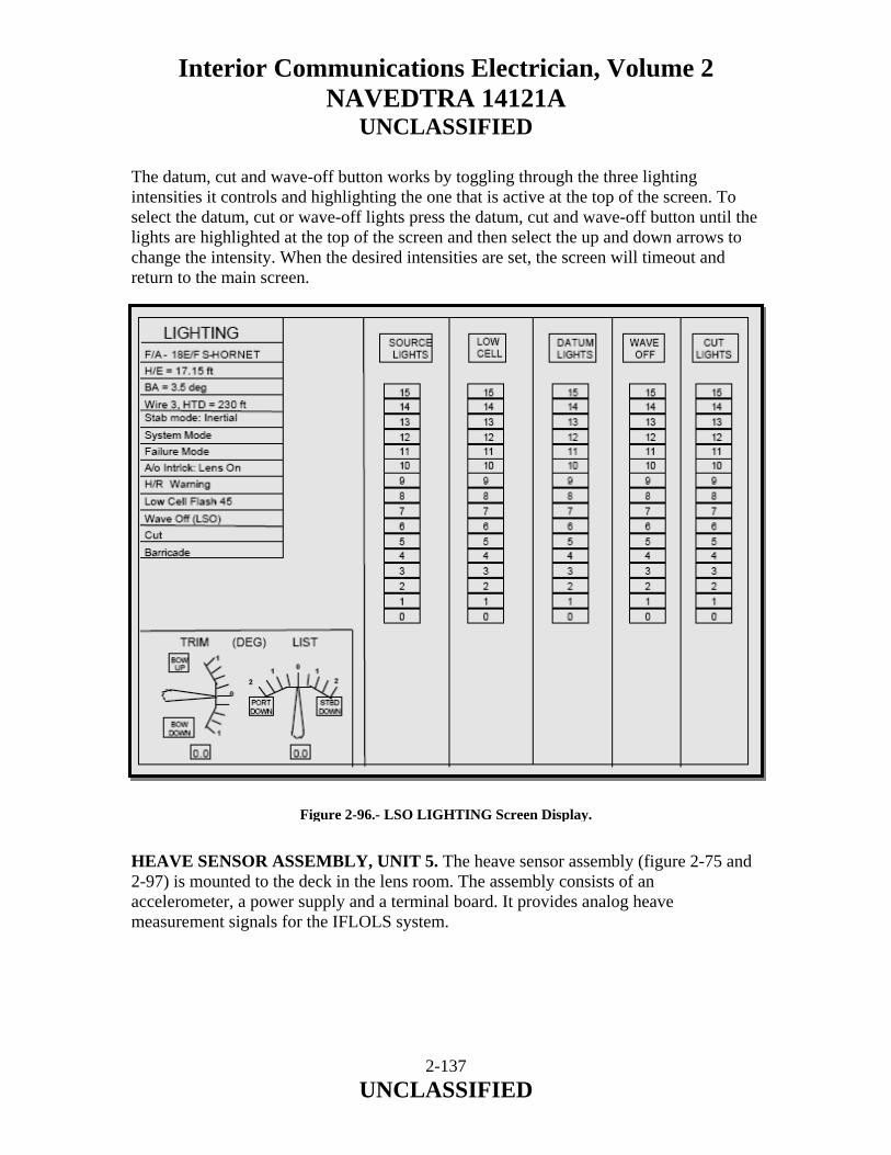
Interior Communications Electrician, Volume 2 NAVEDTRA 14121A
UNCLASSIFIED
The datum, cut and wave-off button works by toggling through the three lighting intensities it controls and highlighting the one that is active at the top of the screen. To select the datum, cut or wave-off lights press the datum, cut and wave-off button until the lights are highlighted at the top of the screen and then select the up and down arrows to change the intensity. When the desired intensities are set, the screen will timeout and return to the main screen.
Figure 2-96.- LSO LIGHTING Screen Display. HEAVE SENSOR ASSEMBLY, UNIT 5. The heave sensor assembly (figure 2-75 and 2-97) is mounted to the deck in the lens room. The assembly consists of an accelerometer, a power supply and a terminal board. It provides analog heave measurement signals for the IFLOLS system.
2-137 UNCLASSIFIED
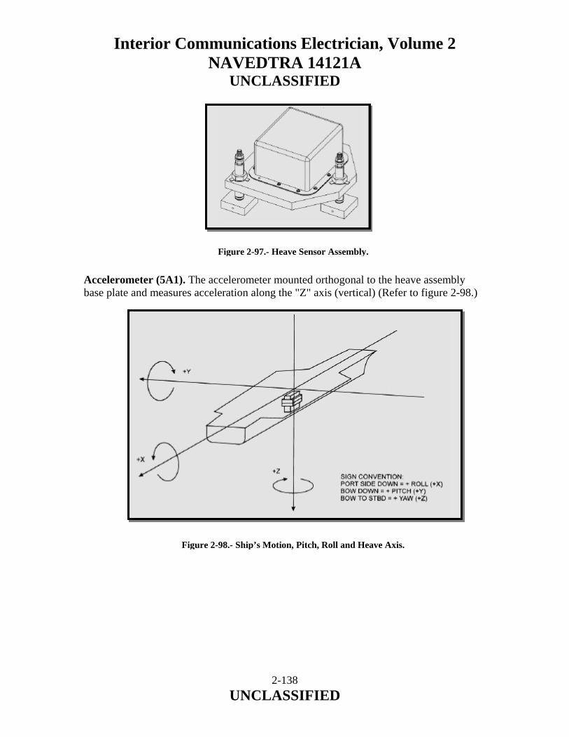
Interior Communications Electrician, Volume 2 NAVEDTRA 14121A
UNCLASSIFIED
Figure 2-97.- Heave Sensor Assembly. Accelerometer (5A1). The accelerometer mounted orthogonal to the heave assembly base plate and measures acceleration along the "Z" axis (vertical) (Refer to figure 2-98.)
Figure 2-98.- Ship’s Motion, Pitch, Roll and Heave Axis.
2-138 UNCLASSIFIED
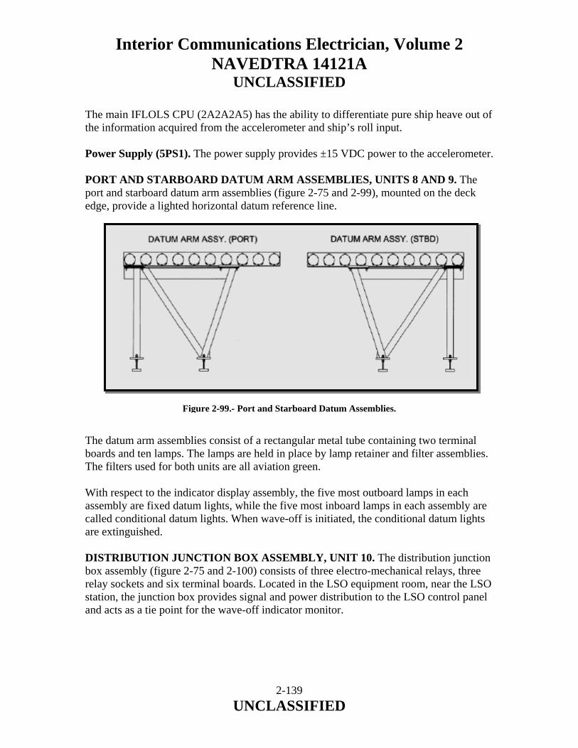
Interior Communications Electrician, Volume 2 NAVEDTRA 14121A
UNCLASSIFIED
The main IFLOLS CPU (2A2A2A5) has the ability to differentiate pure ship heave out of the information acquired from the accelerometer and ship’s roll input. Power Supply (5PS1). The power supply provides ±15 VDC power to the accelerometer. PORT AND STARBOARD DATUM ARM ASSEMBLIES, UNITS 8 AND 9. The port and starboard datum arm assemblies (figure 2-75 and 2-99), mounted on the deck edge, provide a lighted horizontal datum reference line.
Figure 2-99.- Port and Starboard Datum Assemblies. The datum arm assemblies consist of a rectangular metal tube containing two terminal boards and ten lamps. The lamps are held in place by lamp retainer and filter assemblies. The filters used for both units are all aviation green. With respect to the indicator display assembly, the five most outboard lamps in each assembly are fixed datum lights, while the five most inboard lamps in each assembly are called conditional datum lights. When wave-off is initiated, the conditional datum lights are extinguished. DISTRIBUTION JUNCTION BOX ASSEMBLY, UNIT 10. The distribution junction box assembly (figure 2-75 and 2-100) consists of three electro-mechanical relays, three relay sockets and six terminal boards. Located in the LSO equipment room, near the LSO station, the junction box provides signal and power distribution to the LSO control panel and acts as a tie point for the wave-off indicator monitor.
2-139 UNCLASSIFIED

Interior Communications Electrician, Volume 2 NAVEDTRA 14121A
UNCLASSIFIED
Figure 2-100.- Distribution Junction Box Assembly. The junction box assembly also distributes signals to other systems external to IFLOLS. It provides a distribution point for ship trim, ramp motion and wave-off to the LSO HUD. It also sends a wave-off signal to the AN/SPN-46 radar. The LSO wave-off panel switch and portable switch assemblies are also connected to IFLOLS via Unit 10. PORT AND STARBOARD WAVE-OFF/CUT LAMP ARM ASSEMBLIES, UNITS 11 AND 12. The port and starboard wave-off/cut lamp arm assemblies (figure 2-101) consist of eight lamp-housing assemblies each. Cut Lights. In both units the two top most lamps, side by side, utilize aviation green filters and are CUT lights. Wave-Off Lights. The three lamp housings, utilizing red filters and mounted vertically on the outboard side of both units, with respect to the indicator display assembly, constitute the wave-off lights. Emergency Wave-Off Lights. The three lamp housings, utilizing red filters and mounted vertically on the inboard side of both assemblies with respect to the indicator display assembly, constitute the emergency wave-off lights.
2-140 UNCLASSIFIED
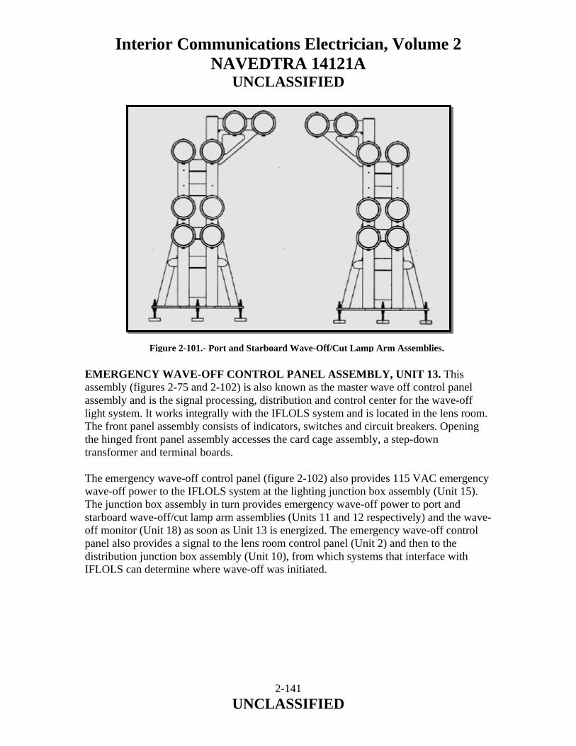
Interior Communications Electrician, Volume 2 NAVEDTRA 14121A
UNCLASSIFIED
Figure 2-101.- Port and Starboard Wave-Off/Cut Lamp Arm Assemblies. EMERGENCY WAVE-OFF CONTROL PANEL ASSEMBLY, UNIT 13. This assembly (figures 2-75 and 2-102) is also known as the master wave off control panel assembly and is the signal processing, distribution and control center for the wave-off light system. It works integrally with the IFLOLS system and is located in the lens room. The front panel assembly consists of indicators, switches and circuit breakers. Opening the hinged front panel assembly accesses the card cage assembly, a step-down transformer and terminal boards. The emergency wave-off control panel (figure 2-102) also provides 115 VAC emergency wave-off power to the IFLOLS system at the lighting junction box assembly (Unit 15). The junction box assembly in turn provides emergency wave-off power to port and starboard wave-off/cut lamp arm assemblies (Units 11 and 12 respectively) and the wave-off monitor (Unit 18) as soon as Unit 13 is energized. The emergency wave-off control panel also provides a signal to the lens room control panel (Unit 2) and then to the distribution junction box assembly (Unit 10), from which systems that interface with IFLOLS can determine where wave-off was initiated.
2-141 UNCLASSIFIED

Interior Communications Electrician, Volume 2 NAVEDTRA 14121A
UNCLASSIFIED
Figure 2-102.- Emergency Wave-Off Control Panel.
2-142 UNCLASSIFIED

Interior Communications Electrician, Volume 2 NAVEDTRA 14121A
UNCLASSIFIED
LIGHTING JUNCTION BOX ASSEMBLY, UNIT 15. The lighting junction box assembly (figure 2-75 and 2-103), located on the deck edge, provides electrical connection points for IFLOLS wave-off, emergency wave-off and cut lighting components. The assembly consists of an enclosure and two terminal boards.
Figure 2-103.- Lighting Junction Box Assembly. TRANSFORMER ENCLOSURE ASSEMBLY, UNIT 16. The transformer enclosure assembly (figure 2-75 and 2-104), located on the deck edge, consists of four transformers and three terminal boards. The assembly provides 20 VAC to the indicator display assembly lamps and 28 VAC to the port and starboard datum arm lamps.
Figure 2-104.- Transformer Enclosure Assembly.
2-143 UNCLASSIFIED

Interior Communications Electrician, Volume 2 NAVEDTRA 14121A
UNCLASSIFIED
WAVE-OFF INDICATOR MONITOR ASSEMBLY, UNIT 18. The wave-off monitor (figure 2-105) consists of a red domed aircraft warning light and is of the approximate dimensions given in table 2-13. There are two wave-off monitor assemblies, one located on forward side of Unit 12 and the other located aft of the LSO workstation. They flash at the same rate as the wave-off lights and provide an indication, which can be seen in the LSO workstation, Pri-Fly and bridge areas that a wave-off has been initiated.
Figure 2-105- Wave-Off Indicator Monitor Assembly. LSO PORTABLE SWITCH ASSEMBLY, UNIT 17. The portable "PICKLE" switch assembly (figure 2-106) consists of a pistol-grip type handle, a gray push-button switch (cut light switch) and a red push-button switch (WAVE-OFF light switch). The portable switch assembly permits the LSO to control the operation of cut lights, wave-off lights and emergency wave-off lights from points other than the LSO panel. There are three LSO portable switch assemblies available at any time for use in initiating cut lights, wave-off lights or emergency wave-off lights.
2-144 UNCLASSIFIED
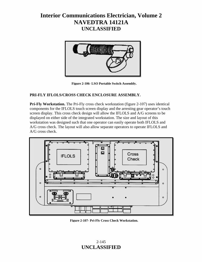
Interior Communications Electrician, Volume 2 NAVEDTRA 14121A
UNCLASSIFIED
Figure 2-106- LSO Portable Switch Assembly. PRI-FLY IFLOLS/CROSS CHECK ENCLOSURE ASSEMBLY. Pri-Fly Workstation. The Pri-Fly cross check workstation (figure 2-107) uses identical components for the IFLOLS touch screen display and the arresting gear operator’s touch screen display. This cross check design will allow the IFLOLS and A/G screens to be displayed on either side of the integrated workstation. The size and layout of this workstation was designed such that one operator can easily operate both IFLOLS and A/G cross check. The layout will also allow separate operators to operate IFLOLS and A/G cross check. Figure 2-107- Pri-Fly Cross Check Workstation.
2-145 UNCLASSIFIED

Interior Communications Electrician, Volume 2 NAVEDTRA 14121A
UNCLASSIFIED
Cross Check Dimmer Panel Assembly. The dimmer panel assembly provides system on/off and intensity control for the cross check flat panel display, the display control module and the EL backlighting panel of the intensity control module. The module consists of a voltage regulator assembly power switch and two potentiometers. 3.5 Inch Floppy Drive Assembly. The 3.5-inch floppy drive assembly allows recovery log data to be downloaded to a 3.5-inch floppy disc that can be uploaded to the ASRL program. Card Cage Assembly. The card cage assembly contains four circuit cards necessary for system operation.
a. 16 Channel Digital Output Card. b. Synchro to Digital Converter Card. c. CPU Circuit Card. d. Serial Communication Circuit Card.
Cross Check Flat Panel Assembly (A5). The Pri-Fly A/G cross check flat panel assembly allows the entering of data to initialize the system to enter sunrise and sunset times, to pre-enter a list of aircraft side numbers and miscellaneous data as appropriate. This data will typically be entered when the system is initially powered up and then updated at least once each operational day during the pre-ops of the system. During recovery operations, the flat panel assembly allows the A/G engine weight settings to be automatically set and then verifies that all engines are properly set, sub-systems are in "Battery" and performs the cross check function of verifying that the arresting gear and Improved Fresnel Lens Optical Landing System (IFLOLS) are both set for the same aircraft type. MOVLAS Operations Entry Screen. If MOVLAS is being used, the A/G Pri-Fly operator must enter this into the cross check system so that the system does not try to get a cross check verification with IFLOLS. NOTE Paragraphs 156/157 are applicable to installations with IFLOLS S/C 4 and A/G S/C 440 installed.
2-146 UNCLASSIFIED

Interior Communications Electrician, Volume 2 NAVEDTRA 14121A
UNCLASSIFIED
(A/G) Pri-Fly Operations Panel. The installation of a dual opto-isolated RS-485 communication card allows transmission of IFLOLS hook-to-eye and basic angle information to A/G cross check. If the IFLOLS settings match the required settings for the aircraft type selected on the A/G panel, the LENS symbology on the air officer's panel displays in green. 2.9.0 MANUALLY OPERATED VISUAL LANDING AID SYSTEM (MOVLAS) The MOVLAS is a backup visual landing aid system used when the primary optical system (IFLOLS) is inoperable, when stabilization limits are exceeded or unreliable (primarily due to extreme sea states causing a pitching deck), and for pilot/LSO training. The system is designed to present glide slope information in the same visual form presented by the IFLOLS. There are three installation modes aboard ship: STATION 1 is immediately in front of the IFLOLS and utilizes the IFLOLS wave-off, datum, and cut light displays. STATION 2 and 3 are independent of the IFLOLS and are located on the flight deck port and starboard side respectively. 2.9.1 MOVLAS Components Lightbox MOVLAS is a vertical series of orange lamps manually controlled by the LSO with a hand controller to simulate the ball. Hand Controller The hand controller is located at the LSO workstation. A handle is provided so the LSO may select the position of the meatball. The pickle switch is attached to the end of the controller handle. As the handle on the LSO controller is moved up or down it lights three or four consecutive lamps in the light box thus providing a meatball. Repeaters MOVLAS repeaters show where the LSO is displaying the meatball to the pilot. One repeater is displayed on the Integrated Launch And Recovery Television Surveillance System (ILARTS).
2-147 UNCLASSIFIED
Interior Communications Electrician, Volume 2 NAVEDTRA 14121A
UNCLASSIFIED
2.9.2 IFLOLS MOVLAS Mode MOVLAS mode is chosen when the IFLOLS cannot utilize active mode while air operations are being performed. This mode needs to be chosen, it is not an automatic mode selected by the IFLOLS. a. Utilize MOVLAS mode: during periods of rough seas when the IFLOLS can no longer stabilize (pitch angle greater than +/- 1.62 degrees or roll +/- 8.19 degrees) and the system exits the active mode and enters the calibration mode. b. When MOVLAS mode is chosen, the source and low cell lights will be turned off and the datum lights will turn on and return to their original intensity setting. c. The port and starboard DC motors (in Unit 1) are disabled in the MOVLAS mode. d. While in the MOVLAS mode, the dynamic hook-to-ramp and hook touchdown meters will operate up to the graphical limits on the main screen display at all stations. If these limits are exceeded, the display will stop at the extreme and resume when the reading(s) fall back within the graphical range. e. MOVLAS mode allows for +/- 2.5 degrees of ship’s pitch and +/- 10 degrees of ship’s roll without giving an alarm. f. The System status area on the flat panel screen will display “MOVLAS” on the first line (A/C hook to eye) and the system mode line. g. Basic angle and hook touchdown values can still be entered. h. When the MOVLAS button is selected the button grid for hook to eye values will be disabled. i. Commanded position will be sent back from the stabilization computer instead of the feedback position. j. The HUD display and the ILARTS interface are active in MOVLAS mode. k. To exit the MOVLAS mode, select ACTIVE or CALIB from the MODE/STATUS screen in the lens room.
2-148 UNCLASSIFIED

Interior Communications Electrician, Volume 2 NAVEDTRA 14121A
UNCLASSIFIED
2.10.0 INTEGRATED LAUNCH AND RECOVERY TELEVISION SURVEILLANCE SYSTEM (ILARTS) 2.10.1 Overview The Integrated Launch and Recovery Television Surveillance (ILARTS) System monitors/records day and night flight ops via LLL (Low Light Level) Cameras located at key locations on the carrier. Each of the LLL cameras operates from full daylight (100,000 lux) to night (.001 lux). The primary requirements for ILARTS are: a. Provide video to assist in incident analysis. b. Allow the Landing Signal Officer (LSO) to detect flight path deviations and coordinate pilot/aircraft approach maneuvers. c. Directly assist the LSO during recoveries, by providing real-time glide-slope / alignment information. d. Enhance the abilities / capabilities of key activities onboard the ship by providing live video during flight ops. (CIC/AIR OPS, CIC/CACC, PILOT HOUSE, THE FLAG BRIDGE, PRIMARY FLIGHT CONTROL, FLIGHT DECK AMCC, and the LSO PLATFORM) 2.10.2 Island Camera Installation The Island Camera is located 40 feet above the flight deck on the island structure. The operator positions the LLL camera on the aircraft and manipulates the zoom from 4 to 40 degrees to maintain proper framing of the aircraft. The Island Camera is used to identify the aircraft and the arresting wire engaged during recoveries. The Island Camera also covers launches and other key flight deck activity. The island camera unit is mounted on a pedestal equipped with a manually operated pan and tilt head; this, of course, requires that an operator be present in the island camera booth. The island camera station is protected by an enclosure. The enclosure is equipped with red and white lighting, and a jackbox for connection of a sound-powered telephone headset to provide audio communication with the ILARTS control room.
2-149 UNCLASSIFIED

Interior Communications Electrician, Volume 2 NAVEDTRA 14121A
UNCLASSIFIED
2-150 UNCLASSIFIED
CENTERLINE INSTALLATION Two LLL Cameras identified as “Aft” and “Forward” are located at selected positions along the angled deck centerline to provide glide-slope and line-up data during aircraft approach. Both cameras provide 14 degrees 35-minutes horizontal and 10 degrees 58-minutes vertical field of view. Each of the centerline camera installations is enclosed in a compartment approximately 6-feet by 6-feet; the compartment is equipped with a locking access door, 120Vac utility outlets for operation of test equipment and portable power tools for maintenance purposes, a 125-psi air supply line with shut-off valves for clearing lens obstructions, piping connections to ship's drain, and a jackbox for connection of sound-powered telephone headset for audio communication to the ILARTS control room. DECK-EDGE CAMERA INSTALLATION Three LLL Cameras aided by infrared illuminators for night operations are employed for catapult surveillance. Each camera is used to view catapult launch operations, and specifically to record aircraft tow bar engagement into the catapult shuttle spreader. The cameras zoom lens, infrared illuminators, and pan / tilt unit allows the operator to maintain proper coverage of the aircraft. 2.10.3 Control Room All ILARTS cameras are operated from the control room, which contains equipment required for processing, control, and synchronization of the video information. The control room also contains equipment for switching, recording, and distribution of the video signals, as well as the audio signal obtained from the LSO radio to the appropriate activities onboard the ship. The room must be air-conditioned, as the heat dissipation of the ILARTS equipment is about 10 kW. A sound-powered telephone circuit from the control room to the island camera station and each of the centerline camera compartments is required to provide audio communication during operation and maintenance of the system. It is also used for shipboard intermediate level maintenance of the ILARTS equipment. A workbench, cabinets, and stowage space is required for intermediate level maintenance tools and test equipment.
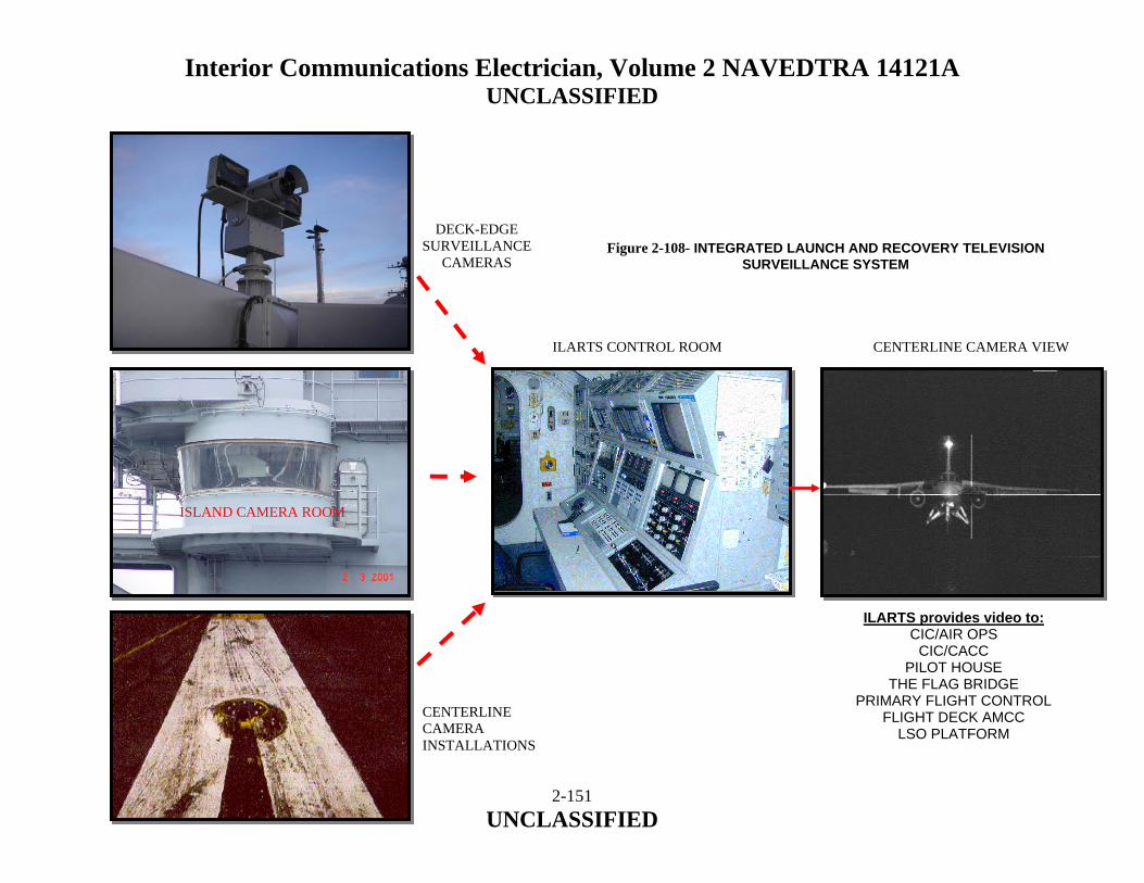
Interior Communications Electrician, Volume 2 NAVEDTRA 14121A UNCLASSIFIED
DECK-EDGE SURVEILLANCE
CAMERAS
ISLAND CAMERA ROOM
CENTERLINE CAMERA VIEW
ILARTS provides video to: CIC/AIR OPS
CIC/CACC PILOT HOUSE
THE FLAG BRIDGE PRIMARY FLIGHT CONTROL
FLIGHT DECK AMCC LSO PLATFORM
CENTERLINE CAMERA INSTALLATIONS
ILARTS CONTROL ROOM
Figure 2-108- INTEGRATED LAUNCH AND RECOVERY TELEVISION SURVEILLANCE SYSTEM
2-151 UNCLASSIFIED
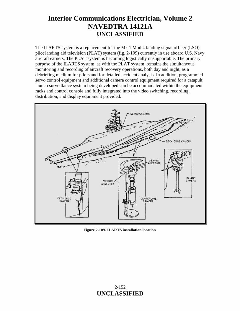
Interior Communications Electrician, Volume 2 NAVEDTRA 14121A
UNCLASSIFIED
The ILARTS system is a replacement for the Mk 1 Mod 4 landing signal officer (LSO) pilot landing aid television (PLAT) system (fig. 2-109) currently in use aboard U.S. Navy aircraft earners. The PLAT system is becoming logistically unsupportable. The primary purpose of the ILARTS system, as with the PLAT system, remains the simultaneous monitoring and recording of aircraft recovery operations, both day and night, as a debriefing medium for pilots and for detailed accident analysis. In addition, programmed servo control equipment and additional camera control equipment required for a catapult launch surveillance system being developed can be accommodated within the equipment racks and control console and fully integrated into the video switching, recording, distribution, and display equipment provided.
Figure 2-109- ILARTS installation location.
2-152 UNCLASSIFIED

Interior Communications Electrician, Volume 2 NAVEDTRA 14121A
UNCLASSIFIED
2.10.4 System Description The ILARTS system is a closed television circuit to monitor aircraft landings aboard U.S. Navy aircraft carriers during both day and night operations, and is planned for expansion to include surveillance of launch operations. Three low-light level television (LLLTV) camera chains, each of which is comprised of a camera head unit (CHU), a camera control unit (CCU), and a remote control panel (RCP), are used in the present system. Two of the CHUs are located at selected positions along the angled deck centerline to provide glide slope and line-up data during the approach. Each of the two centerline CHUs is equipped with a 120mm fixed focal length lens, which provides approximately a 14-degree (horizontal) by 10-degree (vertical) field of view. The centerline CHUs are mounted vertically (below and perpendicular to the flight deck) and view the flight deck through the deck fixture. The deck fixture contains the viewing aperture (window) and a mirror assembly, which provides a means of setting the optical axis (of the 120mm lens/CHU assembly) parallel to the optical glide slope of the incoming aircraft (fig. 2-109). The remaining CHU is located above the flight deck level on the island structure, which provides an unobstructed view of the flight deck. This CHU is used to identify the aircraft and the arresting wire engaged. It is also used to monitor launch operations, accidents, and other flight deck activity. The island camera CHU is equipped with a motor-operated 10:1 zoom lens. The camera housing contains the operator’s viewfinder (monitor) and zoom control. The island camera unit (CHU, zoom lens, and housing) is mounted on a pedestal equipped with a manually operated pan and tilt head (fig. 2-109). This, of course, requires that an operator be present in the island camera booth. The control of the CHU itself is accomplished in the same manner as the centerline CHUs. The CHUs are controlled from a centralized control room that contains equipment required for processing, control, and synchronization. The control room also contains equipment for switching, recording, and distribution of the video signals, as well as audio signals obtained from the LSO radio. Monitoring equipment consisting of a 9-inch or 17-inch monitor and 1-watt loudspeaker are located in each of the selected spaces throughout the ship. 2.10.5 System Installation The shipboard installation of the ILARTS system consists of two centerline camera installations; an island camera station; a centralized control room; and a remotely located monitor installed in the pilot house, each of the squadron ready rooms, and other designated spaces. The general arrangement of the system is shown in figure 2-109.
2-153 UNCLASSIFIED

Interior Communications Electrician, Volume 2 NAVEDTRA 14121A
UNCLASSIFIED
Centerline Camera Installation Two centerline camera installations, identified as Aft and Forward are required to accommodate the range of hook-to-eye values of the various aircraft, and the resultant vertical displacement of the optical glide path. Each of the centerline camera installations is enclosed in a compartment approximately 6-feet by 6-feet, The compartment is equipped with a locking access door; utility outlets at 115 volts, 60 Hz, single phase for operation of test equipment and portable power tools for maintenance purposes; a 125-psi air supply line with shut-off valves; piping connections to ship’s drain; and a jackbox for connection of sound-powered telephone headset for audio communication to the ILARTS control room. Island Camera Station The island camera station is located on the ship’s island structure approximately 40 feet above the flight deck. The island camera station is protected by an enclosure. The enclosure is equipped with 115-volt ac utility outlets for maintenance purposes; red and white lighting; space heaters or forced hot air to keep the enclosure dry when not in operation; drainage facilities for removal of water that may accumulate during operation; and a jackbox for connection of a sound-powered telephone headset to provide audio communication with the ILARTS control room. In addition, electrical power at 115 volts, 60 Hz, single phase, 10 amperes is required for operation of the viewfinder monitor and zoom lens control of the island camera housing. Control Room The ILARTS control room contains all equipment required for operation, control, switching, and distribution of video and audio signals. It is also used for shipboard intermediate level maintenance of the ILARTS equipment. The room should be air-conditioned. The heat dissipation of the ILARTS equipment is 10 kW. A sound-powered telephone circuit from the control room to the island camera station and each of the centerline camera compartments is required to provide audio communication during operation and maintenance of the system. A workbench, cabinets, and stowage space is required for intermediate level maintenance tools and test equipment. Remote Monitors Television monitors and loudspeakers are installed at various designated spaces.
2-154 UNCLASSIFIED
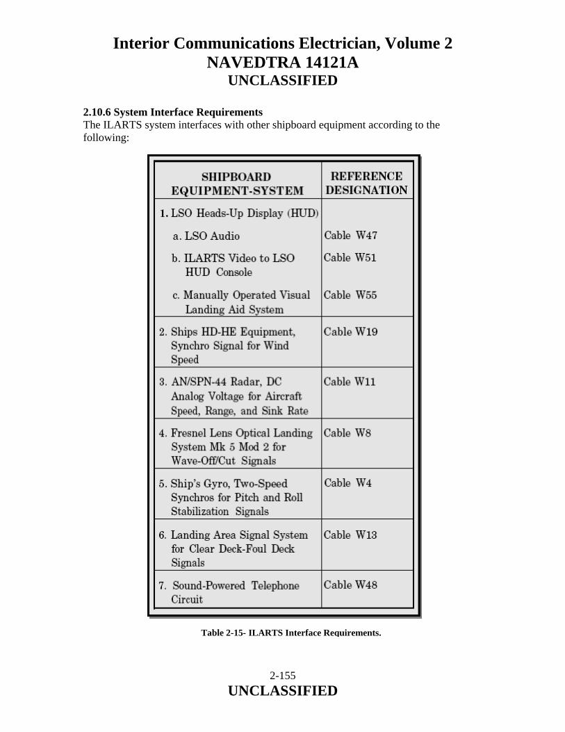
Interior Communications Electrician, Volume 2 NAVEDTRA 14121A
UNCLASSIFIED
2.10.6 System Interface Requirements The ILARTS system interfaces with other shipboard equipment according to the following:
Table 2-15- ILARTS Interface Requirements.
2-155 UNCLASSIFIED

Interior Communications Electrician, Volume 2 NAVEDTRA 14121A
UNCLASSIFIED
2-156 UNCLASSIFIED
2.11.0 SUMMARY In this chapter, we have described the purpose and operation of the ship’s Aviation Equipment Systems. We have identified and discussed the function of the Stabilized Glide Slope Indicator (SGSI) System, various Wave-Off Light Systems, Vertical and Short Take-Off and Landing Optical Landing Systems (VSTOL OLS), Improved Fresnel Lens Optical Landing System (IFLOLS), Manually Operated Visual Landing Aid System (MOVLAS), and the Integrated Launch and Recovery Television Surveillance System (ILARTS). We have briefly discussed some of the preventive and corrective maintenance measures associated with the ship’s Aviation Equipment systems.

Interior Communications Electrician, Volume 2 NAVEDTRA 14121A
UNCLASSIFIED
3 SHIP’S TELEVISION SYSTEMS Upon completion of this chapter, you should be able to do the following:
• Describe the purpose of the various ship's television systems installed on Navy ships.
• Describe basic television system theory. • Describe the Integrated Launch and Recovery Television Surveillance (ILARTS)
System • Describe the Shipboard Information, Training and Entertainment (SITE)
Television System • Describe the Circuit 27 RF Distribution System • Describe the television surveillance systems.
3-1 UNCLASSIFIED

Interior Communications Electrician, Volume 2 NAVEDTRA 14121A
UNCLASSIFIED 3.0.0 INTRODUCTION The television systems used aboard Navy ships provide a wide variety of services to the crew. The television systems can be broken down into two main functions, entertainment and surveillance. The entertainment system is used for dissemination of information, training and entertainment. The ship's entertainment system also provides a medium whereby the commanding officer or commanding officer's representative can address the crew in an informal manner. The surveillance systems provide a means to monitor and record shipboard activities. 3.1.0 BASIC TELEVISION SYSTEM THEORY Television is a rapidly advancing area where IC Electricians are used. Closed-circuit television (CCTV) is receiving wide use throughout the Navy. So broad are the applications of television that special enlisted codes are assigned to the IC Electricians who maintain these systems. In comparing CCTV with commercial television, you will notice how nearly alike they are in operation. The major difference is the methods of transmitting the picture and sound. In CCTV, several methods of transmission are used to bring the signals from the camera to the receiver/monitor. These units are typically connected using coaxial cables for short distances. For greater distances, or when numerous receivers/monitors are involved, transmission is normally accomplished through broadcasting the same media as commercial transmission. This may be accomplished by using a standard transmitter on specially assigned frequencies. When a receiver is used, the receiver is generally a standard television receiver. The monitor is basically the same as the television receiver except that the set does not use a tuner or associated circuits. Most Closed Circuit Television Systems still use the analog video and transmission method. 3.1.1 Televised Information To understand how an analog TV system works, you must know what information is passed from the camera to the receiver. There are four basic kinds of information required:
• Video signal-This signal is the actual moment-to-moment information that tells the receiving set how light or dark each little spot in the picture should be. Unlike movies, in which an entire picture is flashed upon the screen every 1/24th of a second, TV pictures are built up, line by line (525 horizontal lines per picture) and spot by spot within each line. In TV, 30 complete pictures are produced every second.
3-2 UNCLASSIFIED
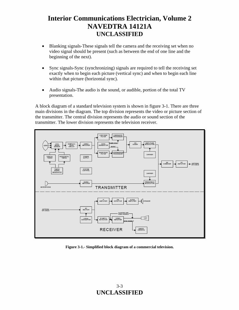
Interior Communications Electrician, Volume 2 NAVEDTRA 14121A
UNCLASSIFIED
• Blanking signals-These signals tell the camera and the receiving set when no video signal should be present (such as between the end of one line and the beginning of the next).
• Sync signals-Sync (synchronizing) signals are required to tell the receiving set exactly when to begin each picture (vertical sync) and when to begin each line within that picture (horizontal sync).
• Audio signals-The audio is the sound, or audible, portion of the total TV
presentation. A block diagram of a standard television system is shown in figure 3-1. There are three main divisions in the diagram. The top division represents the video or picture section of the transmitter. The central division represents the audio or sound section of the transmitter. The lower division represents the television receiver. Figure 3-1.- Simplified block diagram of a commercial television.
3-3 UNCLASSIFIED
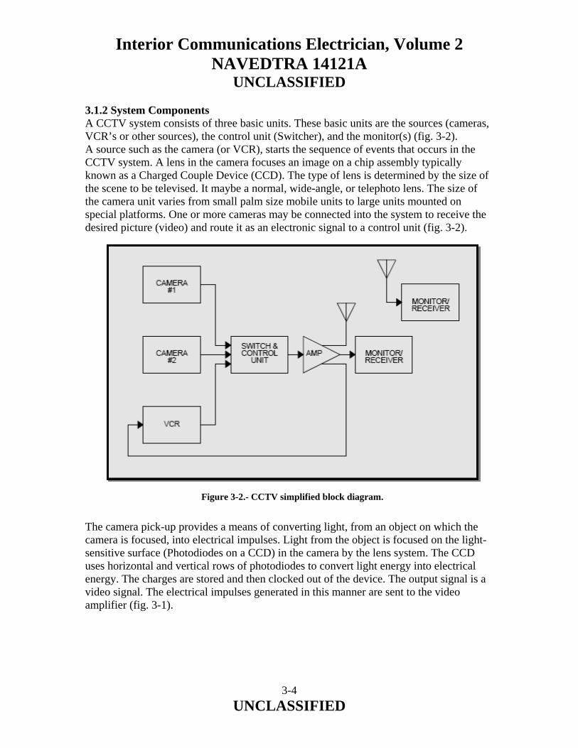
Interior Communications Electrician, Volume 2 NAVEDTRA 14121A
UNCLASSIFIED 3.1.2 System Components A CCTV system consists of three basic units. These basic units are the sources (cameras, VCR’s or other sources), the control unit (Switcher), and the monitor(s) (fig. 3-2). A source such as the camera (or VCR), starts the sequence of events that occurs in the CCTV system. A lens in the camera focuses an image on a chip assembly typically known as a Charged Couple Device (CCD). The type of lens is determined by the size of the scene to be televised. It maybe a normal, wide-angle, or telephoto lens. The size of the camera unit varies from small palm size mobile units to large units mounted on special platforms. One or more cameras may be connected into the system to receive the desired picture (video) and route it as an electronic signal to a control unit (fig. 3-2).
Figure 3-2.- CCTV simplified block diagram. The camera pick-up provides a means of converting light, from an object on which the camera is focused, into electrical impulses. Light from the object is focused on the light-sensitive surface (Photodiodes on a CCD) in the camera by the lens system. The CCD uses horizontal and vertical rows of photodiodes to convert light energy into electrical energy. The charges are stored and then clocked out of the device. The output signal is a video signal. The electrical impulses generated in this manner are sent to the video amplifier (fig. 3-1).
3-4 UNCLASSIFIED

Interior Communications Electrician, Volume 2 NAVEDTRA 14121A
UNCLASSIFIED Control Unit The control unit, as the name implies, is the heart of the system. This unit connects all the other units of the system together. Drive pulses are generated, and they develop the signals required by the camera. Synchronizing and blanking pulses are supplied by the control unit to the receiver/monitor. Video signals from the camera are amplified and distributed to the receiver/monitor. The output signals from the control unit contain vertical and horizontal blanking, sync, and video signals. The control unit consists of the following sections, shown in figure 3-1: video amplifier, control amplifier, carrier, amplitude modulator, radio-frequency (RF) amplifier, sync generator, and the audio controls. Video amplifiers are designed to amplify a wide range of frequencies. The weak electrical impulses from the camera tube are built up by the video amplifier and fed to a control amplifier. The control amplifier combines the video, sync, and blanking signals, all in proper sequence, into a single continuous output to the amplitude modulator. Circuits in the sync generator produce synchronizing (sync) and blanking pulses. These pulses are applied to the control amplifier and become a part of the transmitted signal. Horizontal synchronization makes the horizontal scanning at the receiver occur at the same time as the horizontal scanning at the camera. Vertical synchronization makes the vertical scanning at the receiver keep in step with the vertical scanning at the camera. Sync and blanking signals are also fed to the camera circuits, which develop the necessary control and reference signals. In the carrier, the principal circuit is an oscillator designed to produce a steady, continuous RF signal. Its frequency is fixed and designated by the FCC for the TV station in which it is used. In the amplitude modulator, the carrier signal is modulated by the video, sync, and blanking pulses. The composite (total) signal is then amplified by the RF amplifier and fed to the antenna for radiation into space. The sound portion of the television signal is transmitted by a frequency modulated RF carrier. The sounds are picked up by a microphone, amplified by the audio amplifier, and fed to the frequency modulator section. The sound earner frequency is varied according to the frequency of the audio signal being picked up by the microphone. The frequency modulated signal is then amplified by an R power amplifier. Then it is fed to the antenna for radiation into space, or into a cable system installed throughout the ship.
3-5 UNCLASSIFIED

Interior Communications Electrician, Volume 2 NAVEDTRA 14121A
UNCLASSIFIED Receiver/Monitor The picture-producing unit is commonly referred to as the receiver/monitor unit. The receiver and the monitor (fig. 3-2) differ basically only in the circuits contained in each unit. The media of transmission between the receiver and monitor units are different. This difference requires the receiver to employ additional circuits. (The media employed for the receiver is radio waves, while the media for the monitor is normally cables.) The standard TV receiver contains the same circuits as the monitor, and, in addition, contains the antenna system, tuner, RF amplifiers, and intermediate frequency (IF) amplifiers to receive the transmitted signals. After the IF stage of amplification, the receiver and monitor units are basically the same. Power supplies provide the various voltages needed for the circuits. Audio amplification is basically the same as that used in standard radio receivers. Synchronization is accomplished through the use of a sync circuit with horizontal and vertical sync signals used to control the horizontal and vertical sweep circuits. Video amplification is accomplished through the various video circuits. 3.1.3 Scanning It is easily seen that a picture printed from a photo engraving is made up of a large number of dots. A good example of this is a halftone picture in a newspaper. The lightness or darkness of the picture is determined by the amount of separation between the individual dots. The dots are the elements that make up the picture. A television picture is formed in a similar way. However, there is one very important difference. In the picture made from the photoengraving, all parts of the picture are seen at the same time. In a television picture, the elements are presented individually, one after the other. They are seen in such quick succession that the viewer sees the picture as a whole. To transmit images in this way, it is necessary to use a system of scanning. The image is swept by an electron beam in a systematic manner. During a set period of time all parts of the image are swept by the electron beam. Likewise, in the receiver, where the image is reconstructed, a similar system of scanning is used. CCD Cameras and LCD Monitors clock signals in and out of a device rather than scanning with an electron beam. The principle of scanning can be illustrated by the following example. Assume that you have a flashlight that can produce a very narrow beam of light and that you wish to view a picture on the wall of a dark room. Obviously, because of the narrow beam, you must view a portion of the picture at a time. If you can manipulate the light very fast, you can view the picture in the same manner as the picture would be produced in television. To do this, you would start at the upper left-hand comer of the picture and move the beam rapidly to the right along the top of the picture. When the right-hand edge of the picture is reached, turn off comer of the picture, you have completed a frame.
3-6 UNCLASSIFIED

Interior Communications Electrician, Volume 2 NAVEDTRA 14121A
UNCLASSIFIED Turn the light off and move it to the upper left-hand corner of the picture to start the scanning process over again. The illuminated area scanned by the electron beam is called the RASTER. On the receiving TV tube, it is the area that becomes bright when the brilliance control is turned up with no signal. In older camera tubes and TV picture tubes, an electron beam of small diameter is formed and given the desired velocity by the electron gun, which is located in the neck of the tube. The electron gun in a picture tube or camera tube are the same and correspond to the movement of the flashlight. Deflection (sweeping) of the electron beam across the mosaic/photoconductive material is accomplished by the deflection coils. These are positioned around the neck of the tube. A simplified illustration of scanning is shown in figure 3-3. The beam begins its scan at the upper left-hand comer and moves horizontally along line 1 toward the right. The globules shown are exaggerated in size to simplify the illustration. All of the globules in line 1 are in the bright part. Therefore, they have lost the same number of electrons and accumulated uniform positive charges. The charges are neutralized as the beam sweeps across the globules. As this occurs, a relatively steady current flows from the metal coating of the plate down through a load resistor, which will be discussed later in this chapter. The same situation exists while line 2 is being scanned. Figure 3-3.- Simplified illustration of beam scanning.
3-7 UNCLASSIFIED

Interior Communications Electrician, Volume 2 NAVEDTRA 14121A
UNCLASSIFIED A part of the image is located in line 3, and there is not a steady flow of current through the load resistor as the beam traverses this line. The current flow is steady until the fourth globule is reached. From 4 through 13 the globules have been charged slightly. The discharge current through the load resistor is less when the beam sweeps across the black globules. Beginning with globule 14, the output current increases again. In line 4, the current through the load resistor is steady until the beam reaches globule 4. It then decreases until the beam reaches globule 5. The current through the load resistor then increases and remains steady until the beam reaches globule 13. The current then decreases while the beam is on globule 13 and increases when the beam strikes globule 14. The current through the load resistor then remains steady through the rest of line 4. When the electron beam scans line 5, the current through the load resistor is steady while the beam scans globules 1, 2, and 3. It decreases for globule 4. It comes back to the steady value for globule 5, It decreases again for globules 6 through 11. Then it goes to a steady value for globule 12. It decreases again for globule 13, and then it returns to the steady value for the rest of line 5. The relative strengths of the signal currents are shown at the bottom of fig. 3-3. In a practical camera tube, the globules are extremely small and close together, so the picture will have great detail. Therefore, there must be many changes in current during the course of a single scan. The flow of the tiny pulses of current through a resistor develops signal voltages at the input of the video amplifier. For all of these signal voltages to be passed through the amplifier, the amplifier must be capable of passing a wide band of frequencies. Most modern cameras do not have a tube but a CCD (Charge Couple Device). The CCD contains a grid of millions of tiny devices called photodiodes. When an image is focused on the CCD the light causes the photodiodes to become charged, converting the light into electrons. This is called the photoelectric effect. The more intense the light is at each pixel in the grid, the more charge will be held in that photodiode. The next step is to read the charge of each cell in the image. In a CCD device, the charge is actually transported across the chip and read at one corner of the array. An analog-to-digital converter turns each pixel's value into a digital value. LCD panels are fairly simple to understand. The signal comes in and, as with a CRT; the signal from the video controller is decoded and understood by a display controller on the monitor itself. The controller has two things to control - the electrics of the pixels and the light source.
3-8 UNCLASSIFIED

Interior Communications Electrician, Volume 2 NAVEDTRA 14121A
UNCLASSIFIED The actual image on a panel is made up of a matrix of pixels. Each pixel is made up of three sub-pixels, which have red, green and blue filters in front of them, just as each pixel on a CRT has RGB phosphors. The sub-pixels are made up of a group of liquid crystal molecules. These molecules are suspended between transparent electrodes and are mashed between two polarizing filters. The two filters are exact opposites of each other. As the light from the light source behind the first filter comes in, the filter effectively whites it out - which means that if it was to pass through the liquid crystals with no interaction, the filter on the other side would polarize it back to black, leaving no color being emitted. In fact, alternate current - leaving the crystals 'dark' - is how black is created on a panel. The backlight itself is a cold cathode. These cathodes are diffused through a layer of plastic and then through multiple layers of diffusing material of the kind you might find on a flashgun diffuser for photography. 3.1.4 Flicker The eye retains an image for a fraction of a second (about 1/15 second) after the image is formed on the retina. This characteristic of the eye is used in motion pictures and television. Actually, it is because of this characteristic that it is possible to have motion pictures or television. Motion-picture films are made up of a series of individual pictures (frames) that are shown on the screen in quick succession. The illusion of motion comes because the figures are displaced slightly in succeeding frames. If enough frames are shown per second, the figures appear to move because of the rapid sequence of the frames. At approximately 15 frames per second the motion appears continuous, but there is a pronounced flicker. At 24 frames per second, some flicker is present, but it is much less objectionable than at 15 frames per second. To further reduce the flicker, a special shutter arrangement is used. The shutter cuts off the light from the screen while a new frame is moved into position, it also cuts off the light from the screen once more while the picture frame is stationary. Thus, the shutter divides the presentation of every frame into two equal time intervals. This has essentially the same effect as increasing the frame frequency to 48 frames per second.
3-9 UNCLASSIFIED

Interior Communications Electrician, Volume 2 NAVEDTRA 14121A
UNCLASSIFIED In television, similar problems are encountered. To keep flicker from becoming objectionable, 30 complete frames per second are shown. Flicker is further reduced by interlaced scanning. This has essentially the same effect as increasing the frame frequency to 60 frames per second. The horizontal scanning speed and bandpass requirements of the composite TV signal remain the same. Interlaced scanning is illustrated in figure 4-4. Bandpass considerations, the problems of synchronization, and the necessity for detail lead to the choice of 525 horizontal scanning lines per frame. To reduce flicker by interlaced scanning, the electron beam scans the odd-numbered lines first and then the even numbered lines. Thus, two scans (fields) are necessary to complete one frame. For example, as shown in figure 3-4, the sweep for the first field begins on the left side of line 1. The beam moves across the image plate at a slight downward angle (pulled downward by the vertical deflection coils). At the end of the line, the electron beam is blanked out during the retrace to the left side of line 3. This process is continued until the middle of line 525 is reached. Therefore, 262.5 lines are scanned in the first field. When the beam reaches the middle of the last line, it is blanked out and returned to the middle of line 2 where the trace for the second field starts. The even-numbered lines are scanned in sequence until the end of line 524 is reached. At that instant the beam is blanked out and returned to the beginning of line 1, and the whole process is repeated. Figure 3-4.- Interlaced Scanning.
3-10 UNCLASSIFIED

Interior Communications Electrician, Volume 2 NAVEDTRA 14121A
UNCLASSIFIED Synchronizing and blanking signals are transmitted by the transmitter to keep the movement of the electron beams in the camera and picture tube in step. These signals also blank out the signals from the picture tube during the horizontal and vertical retrace periods. Sequential scanning differs from interlace scanning in the method of moving the electron beam down the screen. The sequential system can be compared to reading a page of print. Each line is read in turn instead of every other line as in interlace scanning. If 60 complete frames are scanned per second, flicker does not exist. However, unless the system has a very broad bandpass, resolution would decrease due to the high video frequencies (extremely fast changing current levels through the load resistor) being produced. The horizontal scanning speed would have to be doubled and would introduce other problems with extremely high frequencies. 3.1.5 Composite Signal Blanking signals are used in both the camera tube and the picture tube control circuits. These signals cut off the electron beam at the end of a horizontal scan line so that the return trace does not produce picture signals at the transmitter or receiver picture tube. Blanking signals are also used to cut off the vertical return trace following the scan of each field. Superimposed on the blanking signals are the synchronizing signals. These signals trigger the vertical sweep circuits and synchronize the horizontal sweep circuits of the receiver/monitor. The horizontal sync signals trigger the horizontal sweep at the correct instant 15,750 times per second (the horizontal sweep frequency). The vertical sync signals trigger the vertical sweep at the correct instant 60 times a second. Figure 3-5 shows the composite signal that produces the scanning illustrated in figure 3-4. The vertical sync pulses have a special serrated form (see fig. 3-6) preceded and followed by equalizing pulses to produce interlaced scanning. This also keeps the horizontal sweep locked in step during the vertical retrace period. All television receivers must perform basically the same functions. They must select the desired carrier frequency. They must amplify the required band of frequencies and separate and demodulate the video and audio frequencies. They must be separated to use the sync pulses to reproduce the picture on the screen and sound at the speaker. How well each job is done depends largely on the design and quality of the TV receiver.
3-11 UNCLASSIFIED
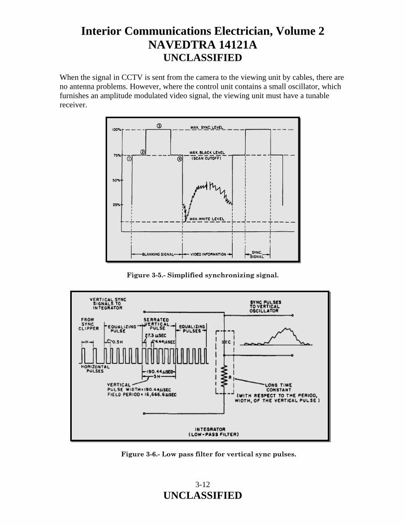
Interior Communications Electrician, Volume 2 NAVEDTRA 14121A
UNCLASSIFIED When the signal in CCTV is sent from the camera to the viewing unit by cables, there are no antenna problems. However, where the control unit contains a small oscillator, which furnishes an amplitude modulated video signal, the viewing unit must have a tunable receiver.
Figure 3-5.- Simplified synchronizing signal. Figure 3-6.- Low pass filter for vertical sync pulses.
3-12 UNCLASSIFIED

Interior Communications Electrician, Volume 2 NAVEDTRA 14121A
UNCLASSIFIED 3.1.6 Types of Lenses The desired type of image or the size of camera coverage requires different types of lenses. The size of the lens varies from small and short to large and long. The purpose of the various lenses varies from the wide-angle lens for large area to the telephoto lens for narrow coverage at long distances. A special lens called the zoom lens is used for special effects. This lens can be varied from the normal visual coverage to distant close-ups. In some installations the lens is manually adjusted, while in other TV cameras it is motor driven. The lens may be adjusted either manually or by an automatic motor-driven device. 3.1.7 Color TV It is known that normal vision is in color. The human eye, in association with the brain, picks up the reflected light and imagines the scene in color. When you view a colored painting, the object appears as a solid section of color. But, upon close inspection, it is seen that what appeared as solid color is really individual brush lines. The same method is used in television to make color appear solid on the face of a picture tube. Small spots of color instead of brush lines make up each solid color. 3.1.8 Principles of Color The principles of color presented in the following paragraphs apply specifically to the development of color television pictures. The three primary colors (fig. 3-7) used in television are red, green, and blue. When two primary colors are combined, they produce another color. Figure 3-7 shows three large circles that represent the three additive primary colors. In the center, where all three overlap, the color white is formed. In sections where two primary colors overlap, another color is produced. Green and blue produce cyan (greenish blue). Blue and red produce magenta (bluish red). Red and green produce yellow. The combining of two primary colors, in proportional amounts, produces the new color. However, when all three colors are combined as units and in percentage of color, the result is white. Note the following combination:
• One red unit represents 30 percent red
• One green unit represents 59 percent green
• One blue unit represents 11 percent blue
3-13 UNCLASSIFIED

Interior Communications Electrician, Volume 2 NAVEDTRA 14121A
UNCLASSIFIED Figure 3-7.- The additive primaries. When one unit of green is combined with three units of red, the result is orange. By changing the proportions of red and green, a variety of colors between red and green can be produced. As the proportion of the primary color mixture changes, the resultant color also changes. The color by itself is called the hue. Green leaves have a green hue. A red apple has a red hue. Different hues result from different wavelengths of light. Red has the longest wavelength; violet has the shortest. The term saturation indicates how little a color is diluted by white light. The more a color differs from white, the greater its saturation. A weak blue color has little saturation, while vivid blue is highly saturated. Saturation is interchangeable with the terms purity and chroma. The brightness of a color as perceived by the human eye is called luminance. The human eye sees brightness increase from blue to a peak at green and then decrease again to red. This apparent response curve is the standard CIE (International Commission of Illumination) luminosity (brightness) curve.
3-14 UNCLASSIFIED

Interior Communications Electrician, Volume 2 NAVEDTRA 14121A
UNCLASSIFIED Color resolution is the full three-color reproduction of the red, green, and blue primaries. Monochrome (black-and-white) reproduction is used for the smallest details. For example, in the televised picture of an automobile, the entire body of the car would be in full color. Narrow vertical strips on the frame might be reproduced in two colors, while the outline of the car where it joins the background would be in black and white. 3.1.9 Transmission The camera unit used for color pickup is similar to the black and white camera. However, the color camera unit has three pickup tubes (one for each of the primary colors). Filters and mirrors are used to direct the right color of light to its respective pickup tube. The output of the camera unit provides a red, green, and blue video signal to the matrix system (a circuit that proportions the primary signals to produce the correct brightness and chrominance colors). The three primary colors are identified as R for red, G for green, and B for blue. The matrix section is essentially a resistive voltage divider circuit that proportions the primary color signals to produce the brightness and chrominance signals. With the red, green, and blue color video voltages as inputs, the three video signal output combinations formed are the following:
• Luminance signal designated the Y signal, which contains the brightness variations of the picture information.
• A color video signal designated the Q signal, which corresponds to either green or
purple picture information.
• A color video signal, designated the I signal, which corresponds to either orange or cyan picture information.
The I and Q signals together contain the color information for the chrominance (hue and saturation) signal. The I and Q signals are transmitted to the receiver as the sidebands of a 3.58-MHz subcarrier wave (fig. 3-8). A subcarrier wave is a relatively low-frequency carrier wave that modulates the main carrier wave. The subcarrier frequency remains the same regardless of the channel frequency. Modulating the subcarrier makes it possible to broadcast the color information of the I and Q signals simultaneously without loss of identity. Each can be recovered as a separate signal with the proper timing of the transmitter and the receiver. The combined outputs are designated as the chrominance C signal and are routed to the adder (fig, 3-9).
3-15 UNCLASSIFIED
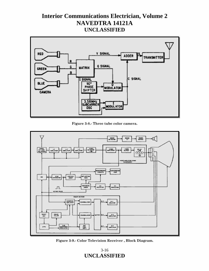
Interior Communications Electrician, Volume 2 NAVEDTRA 14121A
UNCLASSIFIED
Figure 3-8.- Three tube color camera. Figure 3-9.- Color Television Receiver , Block Diagram.
3-16 UNCLASSIFIED
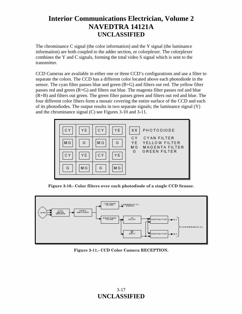
Interior Communications Electrician, Volume 2 NAVEDTRA 14121A
UNCLASSIFIED The chrominance C signal (the color information) and the Y signal (the luminance information) are both coupled to the adder section, or colorplexer. The colorplexer combines the Y and C signals, forming the total video S signal which is sent to the transmitter. CCD Cameras are available in either one or three CCD’s configurations and use a filter to separate the colors. The CCD has a different color located above each photodiode in the sensor. The cyan filter passes blue and green (B+G) and filters out red. The yellow filter passes red and green (R+G) and filters out blue. The magenta filter passes red and blue (R+B) and filters out green. The green filter passes green and filters out red and blue. The four different color filters form a mosaic covering the entire surface of the CCD and each of its photodiodes. The output results in two separate signals; the luminance signal (Y) and the chrominance signal (C) see Figures 3-10 and 3-11. Figure 3-10.- Color filters over each photodiode of a single CCD Sensor. Figure 3-11.- CCD Color Camera RECEPTION.
3-17 UNCLASSIFIED
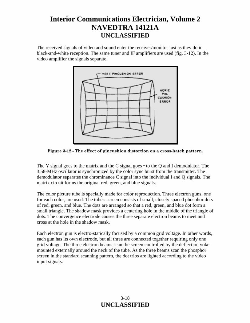
Interior Communications Electrician, Volume 2 NAVEDTRA 14121A
UNCLASSIFIED The received signals of video and sound enter the receiver/monitor just as they do in black-and-white reception. The same tuner and IF amplifiers are used (fig. 3-12). In the video amplifier the signals separate. Figure 3-12.- The effect of pincushion distortion on a cross-hatch pattern. The Y signal goes to the matrix and the C signal goes • to the Q and I demodulator. The 3.58-MHz oscillator is synchronized by the color sync burst from the transmitter. The demodulator separates the chrominance C signal into the individual I and Q signals. The matrix circuit forms the original red, green, and blue signals. The color picture tube is specially made for color reproduction. Three electron guns, one for each color, are used. The tube's screen consists of small, closely spaced phosphor dots of red, green, and blue. The dots are arranged so that a red, green, and blue dot form a small triangle. The shadow mask provides a centering hole in the middle of the triangle of dots. The convergence electrode causes the three separate electron beams to meet and cross at the hole in the shadow mask. Each electron gun is electro-statically focused by a common grid voltage. In other words, each gun has its own electrode, but all three are connected together requiring only one grid voltage. The three electron beams scan the screen controlled by the deflection yoke mounted externally around the neck of the tube. As the three beams scan the phosphor screen in the standard scanning pattern, the dot trios are lighted according to the video input signals.
3-18 UNCLASSIFIED
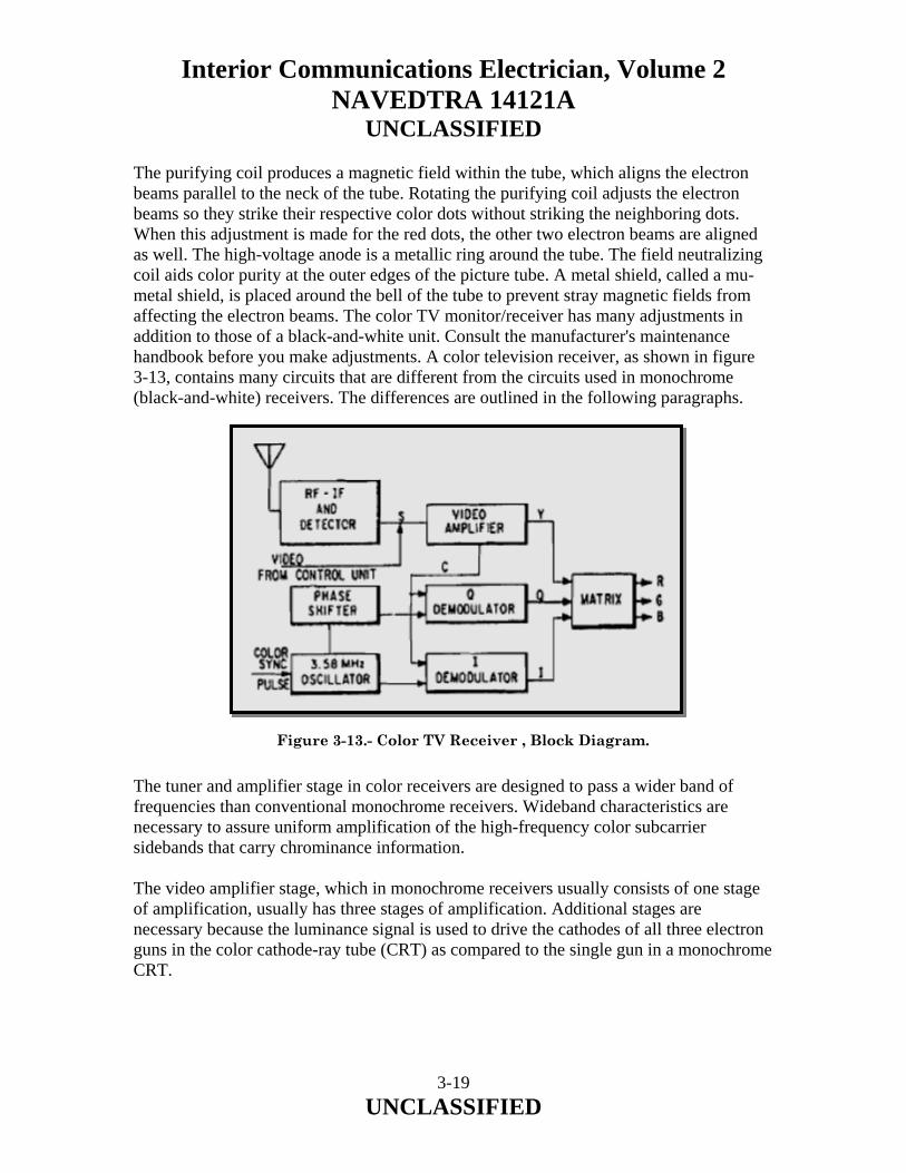
Interior Communications Electrician, Volume 2 NAVEDTRA 14121A
UNCLASSIFIED The purifying coil produces a magnetic field within the tube, which aligns the electron beams parallel to the neck of the tube. Rotating the purifying coil adjusts the electron beams so they strike their respective color dots without striking the neighboring dots. When this adjustment is made for the red dots, the other two electron beams are aligned as well. The high-voltage anode is a metallic ring around the tube. The field neutralizing coil aids color purity at the outer edges of the picture tube. A metal shield, called a mu-metal shield, is placed around the bell of the tube to prevent stray magnetic fields from affecting the electron beams. The color TV monitor/receiver has many adjustments in addition to those of a black-and-white unit. Consult the manufacturer's maintenance handbook before you make adjustments. A color television receiver, as shown in figure 3-13, contains many circuits that are different from the circuits used in monochrome (black-and-white) receivers. The differences are outlined in the following paragraphs.
Figure 3-13.- Color TV Receiver , Block Diagram. The tuner and amplifier stage in color receivers are designed to pass a wider band of frequencies than conventional monochrome receivers. Wideband characteristics are necessary to assure uniform amplification of the high-frequency color subcarrier sidebands that carry chrominance information. The video amplifier stage, which in monochrome receivers usually consists of one stage of amplification, usually has three stages of amplification. Additional stages are necessary because the luminance signal is used to drive the cathodes of all three electron guns in the color cathode-ray tube (CRT) as compared to the single gun in a monochrome CRT.
3-19 UNCLASSIFIED

Interior Communications Electrician, Volume 2 NAVEDTRA 14121A
UNCLASSIFIED A video delay line is usually located between the video output stage and the CRT simultaneously. The fixed delay (fig. 3-9) is necessary because the chrominance signals pass through additional stages before being applied to the control grids of the CRT. Were it not for the delay of luminance information, the two signals would not arrive at the same time. A distorted video presentation would be the result. The use of an aperture mask type of picture tube makes the brightness of a color receiver characteristically low. Therefore, higher voltage is necessary to maintain adequate brightness. The output voltage of the high-voltage supply is nominally 20 to 25 kV as compared with 15 to 18 kV for monochrome receivers. All three electron guns must be sharply focused onto the screen to obtain good monochrome and color reproduction. The focus rectifier in color receivers provides a variable focus voltage (4 to 5 kV) that is applied to the electrostatic focus elements of the CRT. Another factor that requires design techniques much different than monochrome is the load of the high-voltage rectifier must be held fairly constant. Otherwise, severe blooming or shrinking of picture size will occur during the reception of signals with a varying brightness level. The voltage regulator circuit provides a fairly constant anode voltage regardless of the brightness level of incoming signals. The color demodulator section is the ''heart'' of the color television receiver. In this section, the 3.58-MHz subcarrier sidebands are demodulated to produce color information signals. The color information signals are then applied to a matrix. In the matrix, color difference signals are produced by matrixing proportionate amounts of the demodulated signals. The color difference signals are amplified and applied to the control grids of the CRT in the proper proportions to reproduce the televised scene. The color convergence circuits provide a secondary control over the electron beam of each gun. Convergence of the three electron beams to exact locations on the face of the three-gun CRT is necessary to produce good monochrome and color images. Other differences, such as automatic color control, tuning indicators, and color reception indicators, serve to simplify the operation of front-panel controls.
3-20 UNCLASSIFIED
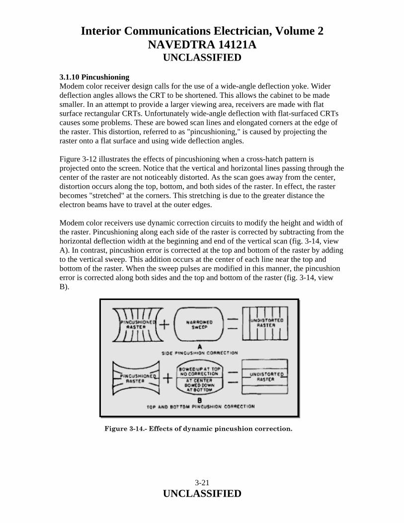
Interior Communications Electrician, Volume 2 NAVEDTRA 14121A
UNCLASSIFIED 3.1.10 Pincushioning Modem color receiver design calls for the use of a wide-angle deflection yoke. Wider deflection angles allows the CRT to be shortened. This allows the cabinet to be made smaller. In an attempt to provide a larger viewing area, receivers are made with flat surface rectangular CRTs. Unfortunately wide-angle deflection with flat-surfaced CRTs causes some problems. These are bowed scan lines and elongated corners at the edge of the raster. This distortion, referred to as "pincushioning," is caused by projecting the raster onto a flat surface and using wide deflection angles. Figure 3-12 illustrates the effects of pincushioning when a cross-hatch pattern is projected onto the screen. Notice that the vertical and horizontal lines passing through the center of the raster are not noticeably distorted. As the scan goes away from the center, distortion occurs along the top, bottom, and both sides of the raster. In effect, the raster becomes "stretched" at the corners. This stretching is due to the greater distance the electron beams have to travel at the outer edges. Modem color receivers use dynamic correction circuits to modify the height and width of the raster. Pincushioning along each side of the raster is corrected by subtracting from the horizontal deflection width at the beginning and end of the vertical scan (fig. 3-14, view A). In contrast, pincushion error is corrected at the top and bottom of the raster by adding to the vertical sweep. This addition occurs at the center of each line near the top and bottom of the raster. When the sweep pulses are modified in this manner, the pincushion error is corrected along both sides and the top and bottom of the raster (fig. 3-14, view B).
Figure 3-14.- Effects of dynamic pincushion correction.
3-21 UNCLASSIFIED

Interior Communications Electrician, Volume 2 NAVEDTRA 14121A
UNCLASSIFIED Although many circuits are presently used to provide dynamic pincushion correction, the end result is always the same; that is, pre-distortion of the sweep current waveform. Basically, this involves decreasing the change rate of the sweep current as it approaches its maximum values. 3.1.11 Automatic Degaussing The metal aperture mask often becomes magnetized when the receiver is moved through the earth's magnetic field, Metal parts in and around the picture tube also become magnetized when a man-made magnetic field collapses or expands in close proximity to the receiver. If these stray fields are allowed to exist, the electron beam from each gun will strike the incorrect phosphor dots on the face of the screen, causing color impurities. Unless the parts have become permanently magnetized due to a prolonged exposure to a strong magnetic field, the magnetism can be canceled by the process of degaussing. During degaussing, a controlled magnetic field is developed by passing alternating current through coils of wire. The magnetic fields thus produced not only cancel the existing stray magnetic fields but also serve to prevent any future buildup. In modem color receivers, the problem presented by stray magnetism is somewhat alleviated by automatic degaussing coils. These coils are an integral part of the color receiver and are usually activated each time the receiver is turned on. The coils, usually from two to four in number, are evenly spaced around the magnetic shield of the receiver picture tube. 3.2.0 SHIPBOARD INFORMATION, TRAINING AND ENTERTAINMENT (SITE) TELEVISION SYSTEM An audiovisual entertainment system combines both audio entertainment and television entertainment into one system. The SITE system is a self-contained, CCTV system that uses video cameras, video cassette recorders, graphic generators, satellite receivers and television receivers. An electronic switching system is the heart of the systems and the outputs are modulated to the applicable television and FM Radio frequencies. The signals are then distributed to television receivers located throughout the ship. The television receivers used with the SITE system are similar to those described earlier in this chapter. The Shipboard Information Training and Entertainment (SITE) systems provide for closed-circuit television (CCTV) program playback aboard U.S. Navy, Military Sealift Command, and U.S. Coast Guard ships. The program content includes command information and public service announcements, military and technical training, copyrighted commercial movies, and programming derived from the American Forces Radio and Television Service (AFRTS) satellite network. The Program is managed by the Defense Media Activity (DMA) - Anacostia.
3-22 UNCLASSIFIED
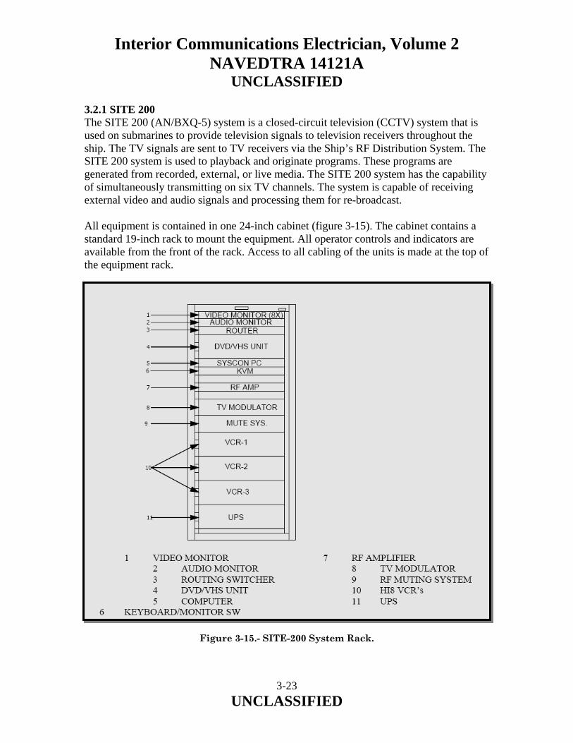
Interior Communications Electrician, Volume 2 NAVEDTRA 14121A
UNCLASSIFIED 3.2.1 SITE 200 The SITE 200 (AN/BXQ-5) system is a closed-circuit television (CCTV) system that is used on submarines to provide television signals to television receivers throughout the ship. The TV signals are sent to TV receivers via the Ship’s RF Distribution System. The SITE 200 system is used to playback and originate programs. These programs are generated from recorded, external, or live media. The SITE 200 system has the capability of simultaneously transmitting on six TV channels. The system is capable of receiving external video and audio signals and processing them for re-broadcast. All equipment is contained in one 24-inch cabinet (figure 3-15). The cabinet contains a standard 19-inch rack to mount the equipment. All operator controls and indicators are available from the front of the rack. Access to all cabling of the units is made at the top of the equipment rack.
Figure 3-15.- SITE-200 System Rack.
3-23 UNCLASSIFIED

Interior Communications Electrician, Volume 2 NAVEDTRA 14121A
UNCLASSIFIED To produce original programming media, the SITE 200 system contains a portable camera. The portable camera permits the media to be recorded for transmission at a later time. The playback of distributed media, such as movies and entertainment programming is facilitated by the use of HI-8 VCR’s. Training material and other Informational material may be played back from the combination DVD/VHS Unit. The transfer of some media through the SITE 200 system is performed electronically with a Routing Switcher. The Routing Switcher routes the media on a point-to-point basis. That is, the video part of the media is routed from a source to a selected destination without any special effects added to the media. Monitoring of the video that is routed through the system is provided on various video monitors. The Routing Switcher routes video and audio signals for the system. The switcher has the capability of 8 inputs and 8 outputs with five wired in the current configuration. Since the inputs of the Routing Switcher are also the outputs of a video source, to prevent confusion, the inputs of the Routing Switcher are referred to as sources. Similarly, the outputs of the Routing Switcher are referred to as destinations. Any of the input sources of the Routing Switcher can be directed to any of the destinations of the Routing Switcher. One input can be directed to more than one destination, but each destination cannot receive an input from more than one source. Any destination can also receive video from one source and the audio from a different source. External TV Broadcasts are available from TV signals received through the Ship's Antenna Feed and Ship's Cable Feed. The receiving capability of the Ship's TV antenna can be used only when the ship is within range (approximately 50 to 80 miles) of the TV transmitter. When the ship is in port and CATV program are available, the cable connection for the CATV program is made through the Ship's Cable Feed. The RF signal is amplified and combined with the RF signal from the output of the RF Modulators for transmission to the TV receivers throughout the ship. As previously mentioned, the same channels that are received from the external TV source cannot be used for TV channels generated from the SITE 200 System. Some cable systems utilize all VHF channels, leaving no channels for the RF Modulators of the SITE System. In this instance, the SITE 200 System cannot be used at the same time the CATV source is being used.
3-24 UNCLASSIFIED

Interior Communications Electrician, Volume 2 NAVEDTRA 14121A
UNCLASSIFIED External video and audio signals may be wired into the SITE system. External jacks are provided that are wired directly to the Routing Switcher and may be directed to the FM and/or Television RF Modulators. This allows external signals to become part of the permanent channel configuration of your system. RF Muting System The system has a RF Muting system that blocks the transmission of the TV channels during announcements and alarms conditions. 3.2.2 SITE 300 The SITE 300 system (AN/UXQ-18) is a closed-circuit television (CCTV) system that is used on smaller class ships to provide television signals to television receivers throughout the ship. The TV signals are sent to TV receivers via the Ship’s RF Distribution System, which is also referred to as the Circuit 14TV (or CKT. 27) Distribution system. The SITE 300 system is used to produce, and originate programs. These programs are generated from recorded, external, or live media. The SITE 300 system has the capability of simultaneously transmitting on 18 TV channels and six FM radio channels. The system is capable of receiving external video and audio signals and processing them for re-broadcast. The Main Equipment Rack is made up of two 24-inch equipment cabinets. Each cabinet contains standard 19-inch rails to mount the equipment. All operator controls and indicators are available from the front of the equipment racks. Access to all cabling of the units is made at the rear of the equipment racks. A rear door is provided for each cabinet of the equipment racks. The equipment racks are shock mounted on spring assemblies to prevent damage due to sharp movement and vibration from the ship. To prevent the equipment racks from swaying, additional springs are attached at the upper rear of the equipment racks, between the equipment racks and an associated support of the ship. To produce original programming media, the SITE 300 system contains a portable camera. The portable camera permits the media to be recorded for transmission at a later time. The playback of recorded media is facilitated by the use of Video Cassette Recorders (VCRs). The current format of VCRs is 8 mm, HI-8mm and VHS. Locally produced material may be stored and played from the Video Recorder. This device will play and record in the DV format as well as from the internal hard drive. Material may be transferred via the Routing Switcher or by tape.
3-25 UNCLASSIFIED

Interior Communications Electrician, Volume 2 NAVEDTRA 14121A
UNCLASSIFIED Text characters are generated by the operator using the Character Generator. The CG is primarily used as a video source for a Command Information (CI) channel. Any available audio may be used as background and is assigned via the Routing Switcher. The transfer of some media through the SITE 300 system is performed electronically with a Routing Switcher. The Routing Switcher routes the media on a point-to-point basis. That is, the video part of the media is routed from a source to a selected destination without any special effects added to the media. Monitoring of the video that is routed through the system is provided on various video monitors. Separate audio panels are used to control the audio portion of the media. The Routing Switcher routes all video and audio signals for the system. The switcher has 16 inputs and 16 outputs. Since the inputs of the Routing Switcher are also the outputs of a video source, to prevent confusion, the inputs of the Routing Switcher are referred to as sources. Similarly, the outputs of the Routing Switcher are referred to as destinations. Any of the input sources of the Routing Switcher can be directed to any of the destinations of the Routing Switcher. One input can be directed to more than one destination, but each destination cannot receive an input from more than one source. Any destination can also receive video from one source and the audio from a different source. One output from the Routing Switcher is supplied to the input of the Video Recorder. This output allows for recording of media produced from the SITE 300 system. The Routing Switcher serves as a device for selecting what programming is delivered to the Distribution System. Some of the TV and FM Modulator inputs are selected from the Routing Switcher outputs (Destinations). The SITE 300 system uses external test equipment. External test equipment is used for system setup, fault isolation and repair of ship’s Distribution System. In addition, the system has patching capabilities that enable a failed component to be patched out of the normal signal path. The SITE 300 receives satellite signals from the AL-7204-DTS Satellite System. The satellite system is capable of receiving either Direct Satellite System (DSS) signals in the Ku band or the TV-DTS signal in the C band. When the Ku band LNB (Low Noise Block converter) is installed the signal may be received on DSS receivers. The DSS Signals are only available when the ship is in range of the commercial satellites (approximately 50 to 100 miles off the US coast), and with a subscription.
3-26 UNCLASSIFIED

Interior Communications Electrician, Volume 2 NAVEDTRA 14121A
UNCLASSIFIED When the C band LNB is installed the signal is fed to seven TV-DTS Integrated Receiver Decoders (IRD’s). IRD1 - IRD3 and IRD5 - IRD-7 are Business models that only receive audio and video, they are also less susceptible to external interference. IRD4 is a Commercial model that is capable of receiving video, audio, and also provides a data connection to the computer system. The computer system may be connected to the ships LAN. The TV-DTS service is a global signal that can be received most anywhere in the world, the IRD's may require adjustments when changing ocean regions. The satellite dish is controlled by an Antenna Control Unit (ACU) which tracks the satellite and provides stability while the ship is at sea. The ACU may be located in the SITE rack or may be mounted in a separate location. The satellite dish focuses the RF signal into a LNB; the LNB is field changeable to receive either Direct Satellite System (DSS) signals in the Ku band or the TV-DTS signal in the C band. The LNB feeds a signal to the SITE system that is distributed to either the DSS or to the TV-DTS receivers for distribution in the SITE system. When the Ku band LNB is installed the signal is fed via two cables to the SITE system. The signals may be sent to DSS receivers (Not Supplied w/ the SITE System) and must be patched into the SITE system for routing to the RF Distribution system. The DSS Signals are only available when the ship is in range of the satellites (approx. 50 to 100 miles off the US coast), and with a subscription. When the C band LNB is installed the signal is fed to the seven TV-DTS Integrated Receiver Decoders (IRD). The Video and Audio signals all feed the Routing Switcher as Sources. IRD4 is a Commercial model decoder which converts the satellite signal to the video, data, and multiple audio signals. The Data connection is permanently wired to the computer. IRD1, IRD2, IRD 3, IRD5, IRD6 and IRD7 are Business model decoders which provide video and audio signals to the SITE Routing Switcher but do not provide all of services of the Commercial IRD. The Business model decoder does provide a more stable signal when in the proximity of external signals, such as radar. In addition to the television AUDIO and VIDEO signals, the IRD’s each provide one monaural audio signal, all are sent to the Routing Switcher to be sent to the FM modulators or as background for CI Video. While receiving the TV-DTS signal only three IRD's are required as there are three signals currently broadcast. In some operating areas, additional AFRTS satellite signals are available and the additional IRD's may be used to receive this expanded coverage.
3-27 UNCLASSIFIED

Interior Communications Electrician, Volume 2 NAVEDTRA 14121A
UNCLASSIFIED External TV Broadcasts are available from TV signals received through the Ship's Antenna Feed and Ship's Cable Feed. The receiving capability of the Ship's TV antenna can be used only when the ship is within range (approximately 50 to 80 miles) of the TV transmitter. When the ship is in port and CATV program are available, the cable connection for the CATV program is made through the Ship's Cable Feed. Either of these two RF input sources is selected by an RF A/B switch. The selected RF signal is amplified and combined with the RF signal from the output of the RF Modulators for transmission to the TV receivers throughout the ship. As previously mentioned, the same channels that are received from the external TV source cannot be used for TV channels generated from the SITE 300 System. Some cable systems utilize all VHF channels, leaving no channels for the RF Modulators of the SITE System. In this instance, the SITE 300 System cannot be used at the same time the CATV source is being used. External video and audio signals may be wired into the SITE system. External jacks are provided that are wired directly to the Routing Switcher (Figure 3-16) and may be directed to the FM and/or Television RF Modulators. This allows external signals to become part of the permanent channel configuration of your system. Inputs may include FM Radio Studio, GBS, DSS, etc…
Figure 3-16.- Routing Switcher.
3-28 UNCLASSIFIED

Interior Communications Electrician, Volume 2 NAVEDTRA 14121A
UNCLASSIFIED 3.2.3 SITE 400 The SITE 400 system (AN/UXQ-19) is a closed-circuit television (CCTV) system that is used on larger ships to provide television signals to television receivers throughout the ship. The TV signals are sent to TV receivers via the Ship’s RF Distribution System, which is also referred to as the Circuit 14TV (or CKT. 27) Distribution system. The SITE 400 system is used as a production studio to produce, edit, and originate programs. These programs are generated from recorded, external, or live media. The SITE 400 system has the capability of simultaneously transmitting on 24 TV channels and six FM radio channels. The system is capable of receiving external video and audio signals and processing them for re-broadcast. The SITE 400 System is composed of three major assemblies: the Main Equipment Rack, the Auxiliary Equipment Rack, and the Ancillary and Test Equipment. The Main Equipment Rack consists of the equipment in two cabinets. The Auxiliary Equipment Rack, consists of the equipment in two cabinets. The Ancillary and Test Equipment of the SITE 400 System consists of the studio camera, a portable camera, portable and studio lighting, various external test equipment, and various associated accessories. To produce original programming media, the SITE 400 system contains both portable and studio cameras. The studio camera permits the media either be sent live, or to be recorded for transmission at a later time. The portable cameras are used primarily to record video and audio at a remote location. There is no provision for direct connection of the portable TV cameras to the SITE 400 system. This capability may be available on some platforms that have an updated Ckt. 27 Distribution System. The video signal output of the studio camera interfaces to the Camera Control Unit (CCU). The CCU permits the setting of the studio camera to be remotely controlled from the SITE 400 System console. The camera video is routed out of the CCU as a composite video (COMP VIDEO) signal that is converted to SDI and supplied to the Production Switcher. Monitoring of the video output of the CCU is provided on Monitor 2-2. An optional Teleprompter system is available for ships that contain a dedicated studio. The playback of recorded media is facilitated by the use of Video Cassette Recorders (VCRs). The current format of the VCRs is 8 mm, HI-8mm and VHS. Locally produced material may be stored and played from the Video Recorder. This device will play and record in the DV format as well as from the internal hard drive. Material may be transferred via the Routing Switcher or by tape.
3-29 UNCLASSIFIED

Interior Communications Electrician, Volume 2 NAVEDTRA 14121A
UNCLASSIFIED Text characters are generated by the operator using one of the Character Generators. CG-1 is a two channel device primarily used in support of local productions. CG-2 is primarily used as a video source for a Command Information (CI) channel. Any available audio may be used as background and is assigned via the Routing Switcher. The SITE 400 system can produce an NTSC color-bar test pattern onto any video output. The color bar pattern can be sent for transmission to the TV receivers in the ship, or can be used at the beginning of a recording. The color bars are used for setting up and testing the video performance of the system. An audio test tone usually accompanies the color-bars that are recorded or are transmitted to the Ship’s RF Distribution system. The transfer of media through the SITE 400 system is performed electronically with a Routing Switcher. The Routing Switcher routes the media on a point-to-point basis. That is, the video part of the media is routed from a source to a selected destination without any special effects added to the media. Monitoring of the video that is routed through the system is provided on various video monitors. Separate audio panels are used to control the audio portion of the media. The Routing Switcher routes all video and audio signals for the system. The switcher has 32 inputs and 32 outputs. Since the inputs of the Routing Switcher are also the outputs of a video source, to prevent confusion, the inputs of the Routing Switcher are referred to as sources. Similarly, the outputs of the Routing Switcher are referred to as destinations. Any of the input sources of the Routing Switcher can be directed to any of the destinations of the Routing Switcher. One input can be directed to more than one destination, but each destination cannot receive an input from more than one source. Any destination can also receive video from one source and the audio from a different source. Two of the video inputs to the Routing Switcher are the output of the Production Switcher. The Production Switcher permits special effects to be added to the media. The corresponding audio input on the Routing Switcher is from the Audio Mixer. Several of the outputs from the Routing Switcher are supplied to the inputs of various record sources. These outputs permit maximum versatility to the configurations available for the media produced from the SITE 400 system. The Routing Switcher serves as the primary device for selecting what programming is delivered to the Distribution System. Most of the TV and FM Modulator inputs are selected from the Routing Switcher outputs (Destinations).
3-30 UNCLASSIFIED

Interior Communications Electrician, Volume 2 NAVEDTRA 14121A
UNCLASSIFIED The Production Switcher has two major outputs: a PROGRAM BUS output and a PREVIEW BUS output. Both outputs are supplied to the input of the Routing Switcher and to an associated Program (PGM) and Preview (PVW) Color Monitor for monitoring purposes. The video contained on the PROGRAM BUS output of the Production Switcher usually contains any desired special effects that have been applied to the signal. The PREVIEW BUS output allows the operator to set up and view a special effect before the operator places it on the PROGRAM BUS. The PROGRAM BUS output is normally considered the final production output and is used in the SITE System for recording onto tape or for routing the signal to the modulators for outputting the signal on the air. Although normally only the PROGRAM BUS output is used to record or send on the air, the PREVIEW BUS output can also perform these functions.
• The CCU receives a BLACK BURST signal from the Sync Test Generator via a Video Distribution Amplifier. (VDA). The BLACK BURST signal provides synchronization for the CCU so the video supplied from the CCU to the Production Switcher will be in phase with the other video sources supplied to the Production Switcher. This synchronization is necessary for proper operation of the Production Switcher. In addition, the CCU receives a Program (PGM) signal. This signal is supplied to the CCU to provide a video image to the monitor of the Studio Camera. This video signal enables the camera person to position the camera into a particular area or scene for special effects purposes.
• The other video sources to the Production Switcher are from CG1, NLE, Video
Recorder and the Routing Switcher. CG1 provides two discreet input channels and the Routing Switcher has one input. Any of these input sources can be selected by the Production Switcher for mixing onto each other to produce special effects and to perform normal studio production techniques.
• CG1 also provide Key signals to the Production Switcher. A key signal is used to
cut a hole in the video that is then filled with the CG video signal. The key signals are fed to individual inputs of the Production Switcher that are selected to cut the key image with the corresponding CG providing the fill signal.
• The video inputs from the Routing Switcher allow the user to select any available
source to be supplied to the Production Switcher.
• Overall synchronization for the Production Switcher is provided by the BB signal provide by the Sync/Test Generator.
3-31 UNCLASSIFIED

Interior Communications Electrician, Volume 2 NAVEDTRA 14121A
UNCLASSIFIED The SITE 400 system uses both internal and external test equipment. The internal test equipment provides continuous monitoring of the parameters of the video and audio being processed and routed through the system. External test equipment is used for system setup, fault isolation and repair of ship’s TV receivers. In addition, the system has patching capabilities that enable a failed component to be patched out of the normal signal path. The SITE 400 receives satellite signals from the AL-7204-DTS single or dual dish configuration. The satellite system is capable of receiving either Direct Satellite System (DSS) signals in the Ku band or the TV-DTS signal in the C band. When the Ku band LNB (Low Noise Block converter) is installed the signal may be received on DSS receivers. The DSS Signals are only available when the ship is in range of the commercial satellites (approximately 50 to 100 miles off the US coast), and with a subscription. When the C band LNB is installed the signal is fed to seven TV-DTS Integrated Receiver Decoders (IRD’s). IRD1 - IRD3 and IRD5 - IRD-7 are Business models that only receive audio and video, they are also less susceptible to external interference. IRD4 is a Commercial model that is capable of receiving video, audio, and also provides a data connection to the computer system. The TV-DTS service is a global signal that can be received most anywhere in the world, the IRD's may require adjustments when changing ocean regions.
• The satellite dish is controlled by an Antenna Control Unit (ACU) which tracks the satellite and provides stability while the ship is at sea. The ACU may be located in the SITE rack or may be mounted in a separate location. The satellite dish focuses the RF signal into a LNB, the LNB is field changeable to receive either Direct Satellite System (DSS) signals in the Ku band or the TV-DTS signal in the C band. The LNB feeds a signal to the SITE system that is distributed to either the DSS or to the TV-DTS receivers for distribution in the SITE system.
• When the Ku band LNB is installed the signal is fed via two cables to the SITE
system. The signals may be sent to DSS receivers (Not Supplied w/ the SITE System) and must be patched into the SITE system for routing to the RF Distribution system. The DSS Signals are only available when the ship is in range of the satellites (approx. 50 to 100 miles off the US coast), and with a subscription.
3-32 UNCLASSIFIED

Interior Communications Electrician, Volume 2 NAVEDTRA 14121A
UNCLASSIFIED
• When the C band LNB is installed the signal is fed to the seven TV-DTS Integrated Receiver Decoders (IRD). The Video and Audio signals all feed the Routing Switcher as Sources. IRD4 is a commercial model decoder which converts the satellite signal to the video, data, and multiple audio signals. The Data connection is permanently wired to the computer. IRD1, IRD2, IRD 3, IRD5, IRD6 and IRD7 are Business model decoders which provide video and audio signals to the SITE Routing Switcher but do not provide all of services of the Commercial IRD. The Business model decoder does provide a more stable signal when in the proximity of external signals, such as radar.
• In addition to the television AUDIO and VIDEO signals, the IRD’s each provide
one monaural audio signal, all are sent to the Routing Switcher to be sent to the FM modulators or as background for CI Video.
• While receiving the TV-DTS signal only three IRD's are required as there are
three signals currently broadcast. In some operating areas, additional AFRTS satellite signals are available and the additional IRD's may be used to receive this expanded coverage.
The SITE 400 System also includes a video editing station. In this configuration, a tape is played from the Camcorder and recorded on the internal hard drive. The material then may be edited to a final production piece. Both the input and output of the editor are available at the Routing Switcher to facilitate the adding of special effects and material from external sources. External TV Broadcasts are available from TV signals received through the Ship's Antenna Feed and Ship's Cable Feed. The receiving capability of the Ship's TV antenna can be used only when the ship is within range (approximately 50 to 80 miles) of the TV transmitter. When the ship is in port and CATV program are available, the cable connection for the CATV program is made through the Ship's Cable Feed. Either of these two RF input sources is selected by an RF A/B switch. The selected RF signal is amplified and combined with the RF signal from the output of the RF Modulators for transmission to the TV receivers throughout the ship. As previously mentioned, the same channels that are received from the external TV source cannot be used for TV channels generated from the SITE 400 System. Some cable systems utilize all VHF channels, leaving no channels for the RF Modulators of the SITE System. In this instance, the SITE 400 System cannot be used at the same time the CATV source is being used. SITE 400 is shown in Figure 3-17.
3-33 UNCLASSIFIED
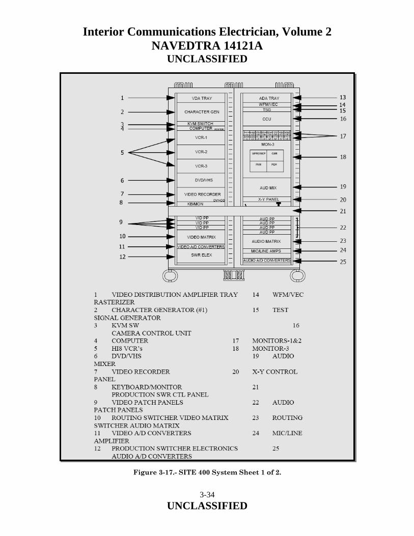
Interior Communications Electrician, Volume 2 NAVEDTRA 14121A
UNCLASSIFIED Figure 3-17.- SITE 400 System Sheet 1 of 2.
3-34 UNCLASSIFIED

Interior Communications Electrician, Volume 2 NAVEDTRA 14121A
UNCLASSIFIED
3-35 UNCLASSIFIED
CG-2 (CI)
RF AMPLIFIER
NLE INTERFACE
(DTS/IRD'S/CG2)
UPS-2
MULTI-SWITCH
TV MODULATOR
COMPUTER
RF COMBINER-2
FM MOD
KVM SWITCH
NLE
MON-4
RF COMBINER-1
ACU
IRD-1
IRD-3
IRD-4
IRD-6
IRD-7
RF SWITCH
EDITOR
UPS-1
IRD-2
IRD-5
FM MOD
AUDIO MONITOR
USB PANEL
KB/MON
TV MODULATOR
26 ANTENNA CONTROL UNIT (ACU) 36 RF SWITCH 27 MONITOR-4 37 RF AMPLIFIER 28 AUDIO MONITOR 38 RF COMBINER 29 NLE INTERFACE 39 FM MODULATORS 30 USB PANEL 40 TV MODULATORS 31 NON-LINEAR EDITOR (NLE) 41 MONITORS- 5 - 8 32 KVM SWITCH 42 CG-2 (CI) 33 KEYBOARD/MONITOR 43 SATELLITE MULTISWITCH 34 DTS COMPUTER 44 SATELLITE IRD 35 UPS Figure 3-17.- SITE 400 System Sheet 2 of 2.

Interior Communications Electrician, Volume 2 NAVEDTRA 14121A
UNCLASSIFIED External video and audio signals may be wired into the SITE system. External jacks are provided that are wired directly to the Routing Switcher and may be directed to the FM and/or Television RF Modulators. This allows external signals to become part of the permanent channel configuration of your system. Inputs may include FM Radio Studio, GBS, DSS, Flight Deck, etc… 3.2.4 SITE 501 The SITE 501 system (AN/UXQ-66) is a closed-circuit television (CCTV) system that is used on Aircraft Carriers to provide television signals to television receivers throughout the ship. The TV signals are sent to TV receivers via the Ship’s RF Distribution System, which is also referred to as the Circuit 14TV (or CKT. 27) Distribution system. The SITE 501 system is used as a production studio to produce, edit, and originate programs. These programs are generated from recorded, external, or live media. The SITE 501 system has the capability of simultaneously transmitting on 24 TV channels and six FM radio channels. The system is capable of receiving external video and audio signals and processing them for re-broadcast. The SITE 501 System is composed of three major assemblies: the Main Equipment Rack, the Auxiliary Equipment Rack, and Ancillary and Test Equipment. The Main Equipment Rack consists of all the equipment in racks 1-4. The Auxiliary Equipment rack consists of all the equipment in racks 5 and 6. The Ancillary and Test Equipment of the system consists of Studio Cameras, ENG Cameras, Lighting, Tele-Prompter Monitors, various external components and Test Equipment. To produce original programming media, the SITE 501 system contains both portable and studio cameras. The studio cameras permit the media either be sent live, or to be recorded for transmission at a later time. The portable cameras are used primarily to record video and audio at a remote location. There is no provision for direct connection of the portable TV cameras to the SITE 501 system. This capability may be available on some platforms that have an updated Ckt. 27 Distribution System. The video signal output of the studio cameras interface to the Camera Control Units (CCU). The CCU’s permit the setting of the studio cameras to be remotely controlled from the SITE 501 System Console. The camera video is routed out of the CCU as a composite video (COMP VIDEO) signal that is supplied to the Production Switcher. Monitoring of the video output of the CCU’s is provided on Monitors 4-1 and 4-2.
3-36 UNCLASSIFIED

Interior Communications Electrician, Volume 2 NAVEDTRA 14121A
UNCLASSIFIED The playback of recorded media is facilitated by the use of Video Cassette Recorders (VCRs). The formats of the VCRs are 8MM, HI8, VHS and DV. The VHS player also incorporates a DVD player. Locally produced material may be stored and played from the Video Recorder. This device will play and record in the DV format as well as from the internal hard drive. Material may be transferred via the Routing Switcher or by tape. Text characters are generated by the operator using one of the Character Generators. CG-1 is a two channel device primarily used in support of local productions. CG-2 is primarily used as a video source for a Command Information (CI) channel. Any available audio may be used as background and is assigned via the Routing Switcher. The SITE 501 system can produce an NTSC color-bar test pattern onto any video output. The color bar pattern can be sent for transmission to the TV receivers in the ship, or can be used at the beginning of a recording. The color bars are used for setting up and testing the video performance of the system. An audio test tone usually accompanies the color-bars that are recorded or are transmitted to the Ship’s RF Distribution system. The transfer of media through the SITE 501 system is performed electronically with a Routing Switcher. The Routing Switcher routes the media on a point-to-point basis. That is, the video part of the media is routed from a source to a selected destination without any special effects added to the media. Monitoring of the video that is routed through the system is provided on various video monitors. Separate audio panels are used to control the audio portion of the media. The Routing Switcher routes all video and audio signals for the system. The switcher has 64 inputs and 64 outputs. Since the inputs of the Routing Switcher are also the outputs of a video source, to prevent confusion, the inputs of the Routing Switcher are referred to as sources. Similarly, the outputs of the Routing Switcher are referred to as destinations. Any of the input sources of the Routing Switcher can be directed to any of the destinations of the Routing Switcher. One input can be directed to more than one destination, but each destination cannot receive an input from more than one source. Any destination can also receive video from one source and the audio from a different source. Two of the video inputs to the Routing Switcher are the output of the Production Switcher. The Production Switcher permits special effects to be added to the media. The corresponding audio input on the Routing Switcher is from the Audio Mixer.
3-37 UNCLASSIFIED

Interior Communications Electrician, Volume 2 NAVEDTRA 14121A
UNCLASSIFIED Several of the outputs from the Routing Switcher are supplied to the inputs of various record sources. These outputs permit maximum versatility to the configurations available for the media produced from the SITE 501 system. The Routing Switcher serves as the primary device for selecting what programming is delivered to the Distribution System. All of the TV and FM Modulator inputs are selected from the Routing Switcher outputs (Destinations). The Production Switcher has two major outputs: a PROGRAM BUS output and a PREVIEW BUS output. Both outputs are supplied to the input of the Routing Switcher and to an associated Program (PGM) and Preview (PVW) Color Monitor for monitoring purposes. The video contained on the PROGRAM BUS output of the Production Switcher usually contains any desired special effects that have been applied to the signal. The PREVIEW BUS output allows the operator to set up and view a special effect before the operator places it on the PROGRAM BUS. The PROGRAM BUS output is normally considered the final production output and is used in the SITE System for recording onto tape or for routing the signal to the modulators for outputting the signal on the air. Although normally only the PROGRAM BUS output is used to record or send on the air, the PREVIEW BUS output can also perform these functions. The CCU’s receive a BLACK BURST signal from the Sync Test Generator via a Video Distribution Amplifier (VDA). The BLACK BURST signal provides synchronization for the CCU’s so the video supplied from the CCU to the Production Switcher will be in phase with the other video sources supplied to the Production Switcher. This synchronization is necessary for proper operation of the Production Switcher. In addition, the CCU receives a Program (PGM) signal. This signal is supplied to the CCU to provide a video image to the monitor of the Studio Camera. This video signal enables the camera person to position the camera into a particular area or scene for special effects purposes. The other video sources to the Production Switcher are from CG1, Video Recorder and the Routing Switcher as well as several patchable inputs. CG1 provides two discreet input channels and the Routing Switcher has two inputs. Any of these input sources can be selected by the Production Switcher for mixing onto each other to produce special effects and to perform normal studio production techniques. The two channels of CG1 also provide Key signals to the Production Switcher. A key signal is used to cut a hole in the video that is then filled with the CG video signal. The key signals are fed to individual inputs of the Production Switcher that are selected to cut the key image with the corresponding CG providing the fill signal.
3-38 UNCLASSIFIED

Interior Communications Electrician, Volume 2 NAVEDTRA 14121A
UNCLASSIFIED The video inputs from the Routing Switcher allow the user to select any available source to be supplied to the Production Switcher. Overall synchronization for the Production Switcher is provided by the SDI BB signal provided by the Sync/Test Generator via the Changeover Switch. The SITE 501 system uses both internal and external test equipment. The internal test equipment provides continuous monitoring of the parameters of the video and audio being processed and routed through the system. External test equipment is used for system setup, fault isolation and repair of ship’s TV receivers. In addition, the system has patching capabilities that enable a failed component to be patched out of the normal signal path. The SITE 501 receives satellite signals from the AL-7204-DTS single or dual dish configuration) or a commercial satellite system. The satellite system is capable of receiving either Direct Satellite System (DSS) signals in the Ku band or the TV-DTS signal in the C band. When the Ku band LNB (Low Noise Block converter) is installed the signal may be received on DSS receivers. The DSS Signals are only available when the ship is in range of the commercial satellites (approximately 50 to 100 miles off the US coast), and with a subscription. When the C band LNB is installed the signal is fed to seven TV-DTS Integrated Receiver Decoders (IRD’s). IRD1 - IRD3 and IRD5 - IRD-7 are Business models that only receive audio and video, they are also less susceptible to external interference. IRD4 is a Commercial model that is capable of receiving video, audio, and also provides a data connection to the computer system. The computer system may be connected to the ships LAN. The TV-DTS service is a global signal that can be received most anywhere in the world, the IRD's may require adjustments when changing ocean regions.
• The satellite dish is controlled by an Antenna Control Unit (ACU) which tracks the satellite and provides stability while the ship is at sea. The ACU may be located in the SITE rack or may be mounted in a separate location. The satellite dish focuses the RF signal into a LNB the LNB is field changeable to receive either Direct Satellite System (DSS) signals in the Ku band or the TV-DTS signal in the C band. The LNB feeds a signal to the SITE system that is distributed to either the DSS or to the TV-DTS receivers for distribution in the SITE system.
• When the Ku band LNB is installed the signal is fed via two cables to the SITE
system. The signals may be sent to DSS receivers (Not Supplied w/ the SITE System) and must be patched into the SITE system for routing to the RF Distribution system. The DSS Signals are only available when the ship is in range of the satellites (approx. 50 to 100 miles off the US coast), and with a subscription.
3-39 UNCLASSIFIED

Interior Communications Electrician, Volume 2 NAVEDTRA 14121A
UNCLASSIFIED
• When the C band LNB is installed the signal is fed to the seven TV-DTS Integrated Receiver Decoders (IRD). The Video and Audio signals all feed the Routing Switcher as Sources. IRD4 is a commercial model decoder which converts the satellite signal to the video, data, and multiple audio signals. The Data connection is permanently wired to the computer. IRD1, IRD2, IRD 3, IRD5, IRD6 and IRD7 are Business model decoders which provide video and audio signals to the SITE Routing Switcher but do not provide all of services of the Commercial IRD. The Business model decoder does provide a more stable signal when in the proximity of external signals, such as radar.
• In addition to the television AUDIO and VIDEO signals, the IRD’s each provide
one monaural audio signal, all are sent to the Routing Switcher to be sent to the FM modulators or as background for CI Video.
• While receiving the TV-DTS signal only three IRD's are required as there are
three signals currently broadcast. In some operating areas, additional AFRTS satellite signals are available and the additional IRD's may be used to receive this expanded coverage.
The SITE 501 System also includes a video editing station. In this configuration, a tape is played from the Camcorder and recorded on the internal hard drive. The material then may be edited to a final production piece. Both the input and output of the editor are available at the Routing Switcher to facilitate the adding of special effects and material from external sources. External TV Broadcasts are available from TV signals received through the Ship's Antenna Feed and Ship's Cable Feed. The receiving capability of the Ship's TV antenna can be used only when the ship is within range (approximately 50 to 80 miles) of the TV transmitter. When the ship is in port and CATV program are available, the cable connection for the CATV program is made through the Ship's Cable Feed. Either of these two RF input sources is selected by an RF A/B switch. The selected RF signal is amplified and combined with the RF signal from the output of the RF Modulators for transmission to the TV receivers throughout the ship. As previously mentioned, the same channels that are received from the external TV source cannot be used for TV channels generated from the SITE 501 System. Some cable systems utilize all VHF channels, leaving no channels for the RF Modulators of the SITE System. In this instance, the SITE 501 System cannot be used at the same time the CATV source is being used. External video and audio signals may be wired into the SITE system. External jacks are provided that are wired directly to the Routing Switcher and may be directed to the FM and/or Television RF Modulators. This allows external signals to become part of the permanent channel configuration of your system. Inputs may include FM Radio Studio, GBS, DSS, Weather, Flight Deck, etc…
3-40 UNCLASSIFIED

Interior Communications Electrician, Volume 2 NAVEDTRA 14121A
UNCLASSIFIED 3.3.0 LOCALLY PREPARED BROADCASTS Commanders may authorize American Forces Radio and Television (AFRT) outlets under their command to originate local programs, which are prepared, produced, or supervised by staff members of the outlet. Live or taped programs should reflect the highest standards of quality. 3.3.1 Prohibited Broadcasts No AFRT station may broadcast or rebroadcast any program sponsored by private or commercial interests or foreign governments, except those programs supplied or authorized by the AFRTS. The prohibition does not apply to live broadcasts of local sport and special events that are prepared initially for broadcast over AFRT, and are presented by, or are under the supervision of, staff members of those stations. In certain instances, events or ceremonies broadcast by a foreign government network or agency may be deemed of sufficient cultural or informational value to warrant rebroadcast by AFRT stations. In addition to the foregoing policies, there are policies governing AFRTS program materials-video and audio tapes, films, slides, and transcriptions. Use or reproduction of AFRTS program materials for private or commercial purposes is prohibited. Use of recorded materials (for example, phonograph records, audio cartridges and cassettes, video cassettes, or films) secured directly from commercial sources, military exchanges, or private sources are prohibited on AFRT outlets. Designated information transcriptions and films produced by DOD may be loaned to command information sections to support information programs. 3.4.0 CIRCUIT 27 RF DISTRIBUTION SYSTEM The Circuit-27 RF Distribution system is used to distribute the RF signals from the SITE System as well as signals from various Surveillance systems throughout the ship. Circuit 27TV consists of industry standard Community Antenna Television (CATV) equipment to provide for the distribution of television signals throughout the ship. The system uses coaxial cable and amplifiers to provide full two-way transmission of audio and video images, with access to most compartments within the ship.
• The two-way capability allows for the integration of all shipboard unclassified television onto one system including SITE TV and other entertainment or information television, and all shipboard surveillance and security camera feeds.
• All shipboard televisions will be connected to the system and will be able to tune in all entertainment, information, and surveillance and security television signals aboard the ship.
3-41
UNCLASSIFIED

Interior Communications Electrician, Volume 2 NAVEDTRA 14121A
UNCLASSIFIED
• Additionally, the system distributes the FM radio band allowing for reception by connected FM radios, of off-air FM broadcasts, or shipboard generated audio programming from the ship’s audio entertainment system, radio station and Armed Forces Satellite Transmitted Radio Service (AFSTRS).
• This system is designated Circuit 27TV and when installed, replaces Circuit 14TV.
Circuit 27TV is composed of two separate signal distribution cables, each with the same transmit (forward) and receive (return) frequency bandwidths. Connection to the system of television receivers, or surveillance/security cameras is made at ship-wide-distributed user service outlets. The two-way capability of the system allows the user service outlet to be either an input or an output to the system.
• The Forward System, or forward feed cable distributes entertainment, training and information television, and FM radio audio throughout the ship. It integrates various television sources including SITE TV, TV at-sea satellite feed, off-air VHF/UHF broadcasts, and pierside CATV, along with various audio sources including ships audio entertainment system, AFSTRS radio program, shipboard radio studio, and off-air FM radio broadcasts. This system’s bandwidth provides capacity for ultimately 110 channels outbound.
• The Return System, or return feed cable accepts as input, video images from
cameras located in various locations of the ship. These cameras transport their individual signals to the system’s headend for distribution throughout the ship. Before distribution, the camera signals must first be modulated from a baseband signal to a specific RF frequency within the 54-750MHz bandwidth. In addition to the fixed surveillance cameras, the Return System accepts as input, live remote camera feeds from anywhere in the ship, to be seen live on all shipboard televisions and recorded for archiving. The Return System provides capacity for 110 standard broadcast channels inbound.
• The headend is the collection point for all video signals including those
mentioned above, as well as the return system signals. It provides for signal processing and leveling of all signals prior to distribution. The headend also provides the means for controlling which of the various video sources are selected for distribution.
3-42 UNCLASSIFIED
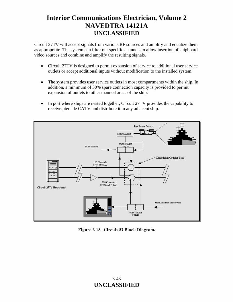
Interior Communications Electrician, Volume 2 NAVEDTRA 14121A
UNCLASSIFIED Circuit 27TV will accept signals from various RF sources and amplify and equalize them as appropriate. The system can filter out specific channels to allow insertion of shipboard video sources and combine and amplify the resulting signals.
• Circuit 27TV is designed to permit expansion of service to additional user service outlets or accept additional inputs without modification to the installed system.
• The system provides user service outlets in most compartments within the ship. In
addition, a minimum of 30% spare connection capacity is provided to permit expansion of outlets to other manned areas of the ship.
• In port where ships are nested together, Circuit 27TV provides the capability to
receive pierside CATV and distribute it to any adjacent ship. Figure 3-18.- Circuit 27 Block Diagram.
3-43 UNCLASSIFIED

Interior Communications Electrician, Volume 2 NAVEDTRA 14121A
UNCLASSIFIED 3.5.0 VIDEO SURVEILLANCE SYSTEMS Many Navy ships are now utilizing Surveillance cameras and system to reduce manpower and to monitor spaces and systems. Defense Media Activity-Anacostia has been assisting in the design, installation and management of many Surveillance Systems. A typical Surveillance System consists of both fixed cameras and Pan/Tilt/Zoom (P/T/Z) cameras connected to a Matrix. The Matrix serves as a switchboard for the cameras. Also connected to the Matrix are Controllers. The controllers allow a user to select and control a camera, view multiple cameras, and playback recorded surveillance video. Video from the cameras is recorded on the Digital Disk Recorder for playback and/or archiving. The system also consists of a rack mounted Personal Computer (PC) to assist in the configuration and troubleshooting of the system as well as containing a DVD Writer to create a permanent archive of the recorded video.
• Fixed Cameras: The system contains numerous fixed cameras. This color camera is housed in a vandal proof enclosure and is set to a fixed position.
• P/T/Z Cameras: The system also contains a number of P/T/Z cameras. P
represents PAN, where the camera moves left or right. The T, or TILT control moves the camera up and down. The Z or ZOOM control move the camera image nearer and farther away. This color camera is mounted in a vandal proof enclosure and can be panned, tilted and zoomed.
• Matrix Switcher: The Matrix Switcher is mounted in the equipment rack and is
the heart of the system. All cameras are connected to the Matrix as well as the controllers and the PC.
• Joystick Controller: The controller is mounted in several user locations and allows
the operator to select and control cameras as well as playback recorded surveillance video.
• System Monitors: The system consists of video monitors mounted at each
monitoring location.
• Digital Disk Recorder (DDR): The digital Disk Recorder, records the incoming surveillance video from the cameras. The video is retained for playback for and can be recorded to CD, DVD or other removable memory devices via the computer.
• System PC: The system contains a rack mounted PC with software to configure
the system. The PC also has a DVD Writer and a memory card interface that allows the system administrator to copy video from the Digital Disk Recorder.
3-44 UNCLASSIFIED

Interior Communications Electrician, Volume 2 NAVEDTRA 14121A
UNCLASSIFIED
3-45 UNCLASSIFIED
3.6.0 SUMMARY In this chapter, we have described the purpose of the ship's video systems installed on Navy ships today and the various equipment used with each type of system. We have also identified the operation and characteristics of the systems.

Interior Communications Electrician, Volume 2 NAVEDTRA 14121A
UNCLASSIFIED
4 TECHNICAL ADMINISTRATION Upon completion of this chapter, you should be able to do the following:
• Describe the system used for equipment calibration. • Identify the calibration echelons established for calibrating equipment. • Describe the Metrology Automated System for Uniform Recall and Reporting
(MEASURE) program. • Recognize the procedure to follow for requesting calibration of equipment. • Describe the different calibration statuses of equipment. • Describe the procedures in updating equipment calibration schedules. • Recognize the procedures used to instruct IC watch standers. • Identify the steps in planning and scheduling work and in assigning tasks and
duties. • Describe the steps in preparing and reviewing casualty reports (CASREPs),
casualty corrections (CASCORs), and situation reports (SITREPs).
4-1 UNCLASSIFIED

Interior Communications Electrician, Volume 2 NAVEDTRA 14121A
UNCLASSIFIED 4.0.0 INTRODUCTION As an IC Electrician Second Class, your administrative responsibilities will include updating various forms and schedules concerning equipment calibration. You will also be responsible for instructing your personnel on IC watch standing. This will include ensuring that your personnel are informed of safety precautions and procedures to follow when they are standing the various IC watches. Therefore, this chapter will give you some background on the Navy Metrology and Calibration (METCAL) program, the Metrology Automated System for Uniform Recall and Reporting (MEASURE) program, and IC watch standing, which will include electrical safety. As an IC Electrician First Class or Chief, you can expect to spend much more time on administrative and supervisory duties. As an administrator, you will assign tasks and fill out required reports and schedules. As a supervisor, you will oversee the work and make sure it is done correctly and on time. As an IC1 or ICC, you may be required to organize and supervise an IC shop aboard ship. This chapter will give you insight into the areas of shop supervision and report preparation and will provide you with useful tools that will help you fulfill your role as a shop supervisor. Some areas of shop supervision are not covered in this chapter. But, you may find information about these areas in other publications, such as the Ship’s Maintenance and Material Management (3-M) Manual, OPNAVINST 4790.4B; Navy Occupational Safety and Health (NAVOSH) Program Manual, OPNAVINST 5100.23G; Navy Safety Precautions for Forces Afloat, OPNAVINST 5100.19B; and Engineering Administration, NAVEDTRA 10858-F. 4.1.0 THE NAVY METROLOGY AND CALIBRATION PROGRAM Metrology is the science and art of measurement for the determination of conformance to technical requirements. It includes the development of standards and systems for absolute and relative measurements. Although measurement methods have changed considerably since ancient times, the basic concept of using calibration to maintain the accuracy of tools and measuring devices to manufacture quality products and maintain quality performance has not changed. Calibration assures us that our weapon systems are working right and that the parts obtained from different manufacturers will fit together as they should. The success of our Navy depends on the use of accurate and reliable measuring instruments, and the best way to assure continued accuracy is by periodic calibration performed by skilled technicians. The increased complexity of ship systems (especially weapons, propulsion, and navigation) has made it necessary to improve the quality and accuracy of measurements. Problems existed in measurements because the measurements of one activity did not agree with those of another activity even though identical items were being measured. In such cases, there was a tendency to “write off” the discrepancies as variations in the measuring instrument. But, in fact, most of any discrepancy was due to the lack of standardized measurements.
4-2 UNCLASSIFIED

Interior Communications Electrician, Volume 2 NAVEDTRA 14121A
UNCLASSIFIED It was the purpose of standardizing instrument measurements that the Navy METCAL program was established. This program emphasizes the need to complete measurement standardization throughout the Navy. The Navy has established the METCAL program to ensure traceability and accuracy of instrument calibration to the National Institute of Standards and Technology (NIST). To operating personnel, this means that any instrument used aboard ship for quantitative measurement must be calibrated and that the standards used are more accurate than the shipboard instruments. The accuracy of a standard must be traceable, through documentation by each higher calibration activity, to the NIST. Each instrument calibrated (including standards) must bear evidence that it is in calibration. This evidence is in the form of a calibration label affixed to the instrument. This label provides the date and place of calibration and the next due date for calibration. The METCAL program provides for periodic calibration of most instruments. The responsibility for assignment of these periodic calibration intervals has been given to the Metrology Engineering Center (MEC). The calibration of all measuring devices is based on, and is dependent upon, the basic international and national standards of measurement. Since we cannot rush off to the NIST every time we need to measure a length, a mass, a weight, or an interval of time, the NIST prepares and issues a great many practical standards that can be used by government and industry to calibrate their instruments. Government and industry, in turn, prepare their own practical standards, which are applicable to their own requirements. Thus, there is a continuous linkage of measurement standards that begins with the international standards, comes down through the national standards, and works all the way down to the rulers, weights, clocks, gauges, and other devices that we use for everyday measurement. For further information and detailed assignment of the METCAL program, refer to NAVMAT Instruction 4355.67. 4.2.0 CALIBRATION TERMS AND DEFINITIONS Before proceeding, it is necessary for us to discuss some of the commonly used terms associated with the instrument calibration program used by the Navy. It is important that you understand the meaning of these terms and use them correctly. Many of these terms will be used throughout this text. Other very important terms are listed in the glossary, appendix II. Refer to it as often as necessary.
4-3 UNCLASSIFIED

Interior Communications Electrician, Volume 2 NAVEDTRA 14121A
UNCLASSIFIED 4.2.1 Calibration Calibration is the act of comparing a measurement system or device of unverified accuracy to a measurement system or device of known and greater accuracy to detect and correct any variation from required performance specifications. The calibration process involves the use of approved instrument calibration procedures (ICPs). It includes any adjustments or incidental repairs that are necessary to bring a standard or an instrument being calibrated within specified limits. 4.2.2 Standard A standard is a laboratory-type device that is used to maintain continuity of value in the units of measurement. Its accuracy is ensured through periodic comparison with higher echelon or national standards. A standard may be used either to calibrate a standard of lesser accuracy or to calibrate test and measurement equipment directly. 4.2.3 Traceability Traceability is the unbroken chain of properly conducted and documented calibration of equipment from the fleet through higher echelons to the National Bureau of Standards (NBS). 4.2.4 Test and Monitoring Systems Test and monitoring systems (TAMS) are the instruments used for all quantitative measurements except metrology standards. TAMS can also be referred to as precision measurement equipment (PME), test and measuring equipment (T&ME), or test, measuring, and diagnostic equipment (TMDE). 4.2.5 Operable Equipment Operable equipment is equipment that before being submitted to calibration is found by review of its performance history and by cursory electrical and physical examinations to be operational in all its required functions. 4.2.6 Incidental Repairs Incidental repairs are those repairs found necessary during calibration of an operable equipment to bring it within its specified tolerances. These include the replacement of parts that, although worn sufficiently to prevent calibration, do not otherwise render the equipment inoperative. This repair work is normally performed incidental to the calibration of standards.
4-4 UNCLASSIFIED
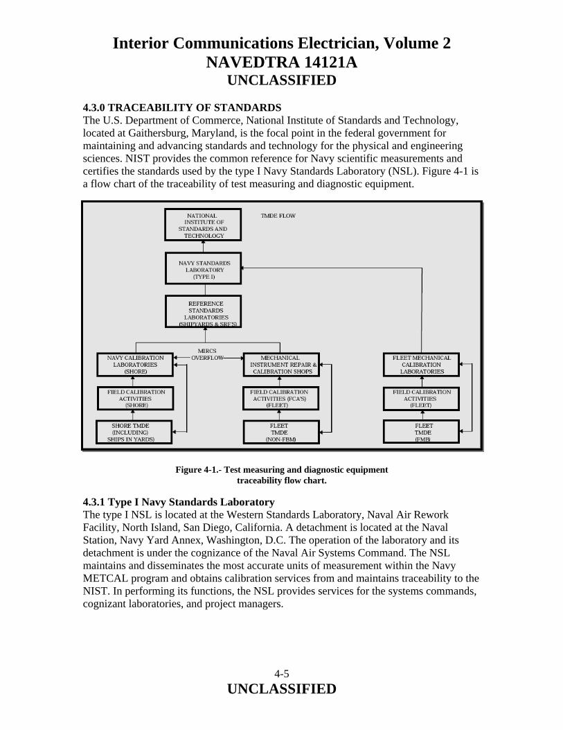
Interior Communications Electrician, Volume 2 NAVEDTRA 14121A
UNCLASSIFIED 4.3.0 TRACEABILITY OF STANDARDS The U.S. Department of Commerce, National Institute of Standards and Technology, located at Gaithersburg, Maryland, is the focal point in the federal government for maintaining and advancing standards and technology for the physical and engineering sciences. NIST provides the common reference for Navy scientific measurements and certifies the standards used by the type I Navy Standards Laboratory (NSL). Figure 4-1 is a flow chart of the traceability of test measuring and diagnostic equipment. Figure 4-1.- Test measuring and diagnostic equipment
traceability flow chart. 4.3.1 Type I Navy Standards Laboratory The type I NSL is located at the Western Standards Laboratory, Naval Air Rework Facility, North Island, San Diego, California. A detachment is located at the Naval Station, Navy Yard Annex, Washington, D.C. The operation of the laboratory and its detachment is under the cognizance of the Naval Air Systems Command. The NSL maintains and disseminates the most accurate units of measurement within the Navy METCAL program and obtains calibration services from and maintains traceability to the NIST. In performing its functions, the NSL provides services for the systems commands, cognizant laboratories, and project managers.
4-5 UNCLASSIFIED

Interior Communications Electrician, Volume 2 NAVEDTRA 14121A
UNCLASSIFIED 4.3.2 Type II Navy Standards Laboratories and Reference Standards Laboratories Type II NSLs and reference standards laboratories (RSLs) provide the second highest echelon of calibration services within the Navy. Type II NSLs obtain standards calibration services from type I NSLs and calibrate standards from lower echelon laboratories. RSLs are similar in capability and operation to the type II NSLs. In addition, shipyard RSLs provide calibration support for mechanical instrumentation. 4.3.3 Navy Calibration Laboratories (SHORE) Navy calibration laboratories (NCLs) obtain calibration services from higher echelon laboratories. The capabilities of these laboratories vary. Their mission is twofold: (1) to maintain standards of measurement within the activity, and (2) to calibrate and repair standards and to calibrate and accomplish incidental repair on fleet and shore activity test and measuring equipment. 4.3.4 Mechanical Instrument Repair and Calibration Shops Mechanical instrument repair and calibration shops (MIRCS) are located on board tenders (other than FBM), repair ships, and specified shore activities. Their function is to calibrate and repair mechanical and electromechanical measuring devices installed aboard ships and submarines. Standards used by MIRCs are submitted to a higher echelon laboratory for calibration. 4.3.5 Fleet Mechanical Calibration Laboratories Fleet mechanical calibration laboratories (FMCLs) are on board FBM submarine tenders to provide calibration services for FBM submarine mechanical, test, and measurement equipment. Standards from these laboratories arc submitted to higher echelon laboratories for calibration. The FMCLs are operated by IM personnel with an 1821 NEC. The basic difference between the MIRCs and the FMCL is that the FMCL has the additional capability for optical calibration. 4.3.6 Fleet Calibration Activities Navy field calibration activities (FCAs) make up the next lower echelon. These activities have been set up to enable user activities to calibrate locally such specific types of instruments as pressure gauges, temperature gauges, and electrical meters, rather than send them to a laboratory. Calibration is performed by specially trained personnel. Most ships in the fleet have designated FCAs.
4-6 UNCLASSIFIED

Interior Communications Electrician, Volume 2 NAVEDTRA 14121A
UNCLASSIFIED 4.4.0 SUPPORT FOR CALIBRATION STANDARDS To receive calibration support for standards, you should take the following steps:
1. Request funds from the type commander. 2. Request calibration services, by official message, from the supporting laboratory. 3. Makeup a recalibration schedule with the help of the supporting laboratory. This schedule will minimize the delay in getting your standards recalibrated and back in service.
4.5.0 METROLOGY AUTOMATED SYSTEM FOR UNIFORM RECALL AND REPORTING In an effort to ensure that all equipment requiring calibration and/or servicing is maintained at maximum dependability, the Chief of Naval Material implemented the MEASURE program. It is the Navy’s single data reporting system for the TAMs and the Navy METCAL program. As an IC Electrician Second Class, you will be required to update calibration schedules. Therefore, you should have a thorough understanding of the MEASURE program and be familiar with the forms and reports used with this system. You will be required to check documents for completeness and accuracy and to assist customers in the completion of these documents. Information on how to use this program effectively and how to complete the necessary documents accurately is provided in the latest edition of the Measure Users Manual, OP43P6. Several documents are used to update the database of the MEASURE system. These documents will be discussed in the following paragraphs. The MEASURE system is a tool for your use. It is only as good as the information that is put into it. It is important that all information be thoroughly legible, accurate, and consistent.
4-7 UNCLASSIFIED

Interior Communications Electrician, Volume 2 NAVEDTRA 14121A
UNCLASSIFIED 4.5.1 Inventory Report Forms The MEASURE Test Measuring and Diagnostic Equipment (TMDE) Inventory Report Form and the MEASURE Calibration Standards Inventory Report Form provide the initial input of data pertaining to TAMS equipment and calibration. This information, when stored in a computer, establishes a data base for all MEASURE forms and reports. NOTE Since computers cannot think, completeness and accuracy of information is essential to make the program effective. Inventory report forms are submitted to an intermediate level activity of FCA for screening. This activity determines whether or not it has the capabilities for the calibration of the equipment listed in the inventory. Items that are outside the capability of this activity are noted on the inventory report form. The report forms are forwarded to a METCAL representative for validation. They are then forwarded to the MEASURE Operational Control Center (MOCC) in Concord, California, and are entered into the data bank. The customer is provided with an automated inventory and a set of preprinted METER cards. Normally, the inventory forms are only used for the initial input of data. However, if 10 or more items are to be added to the inventory, an appropriate inventory report form can be used. This form is prepared in the same manner as the initial inventory report except that the words Add-On-Inventory are entered above the customer activity code block at the top center of the form. 4.5.2 Meter Card The METER card (fig. 4-2) is a five-part, color-coded form to which the equipment identification (ID) and receipt tag is attached. It is filled out by either the customer or the calibrating activity and is used to report information and transactions pertaining to TAMS and calibration standards. The METER card, either preprinted by the MOCC or hand-printed by the customer activity, contains all information necessary to identify a single piece of TAMS equipment and to update the data base.
4-8 UNCLASSIFIED
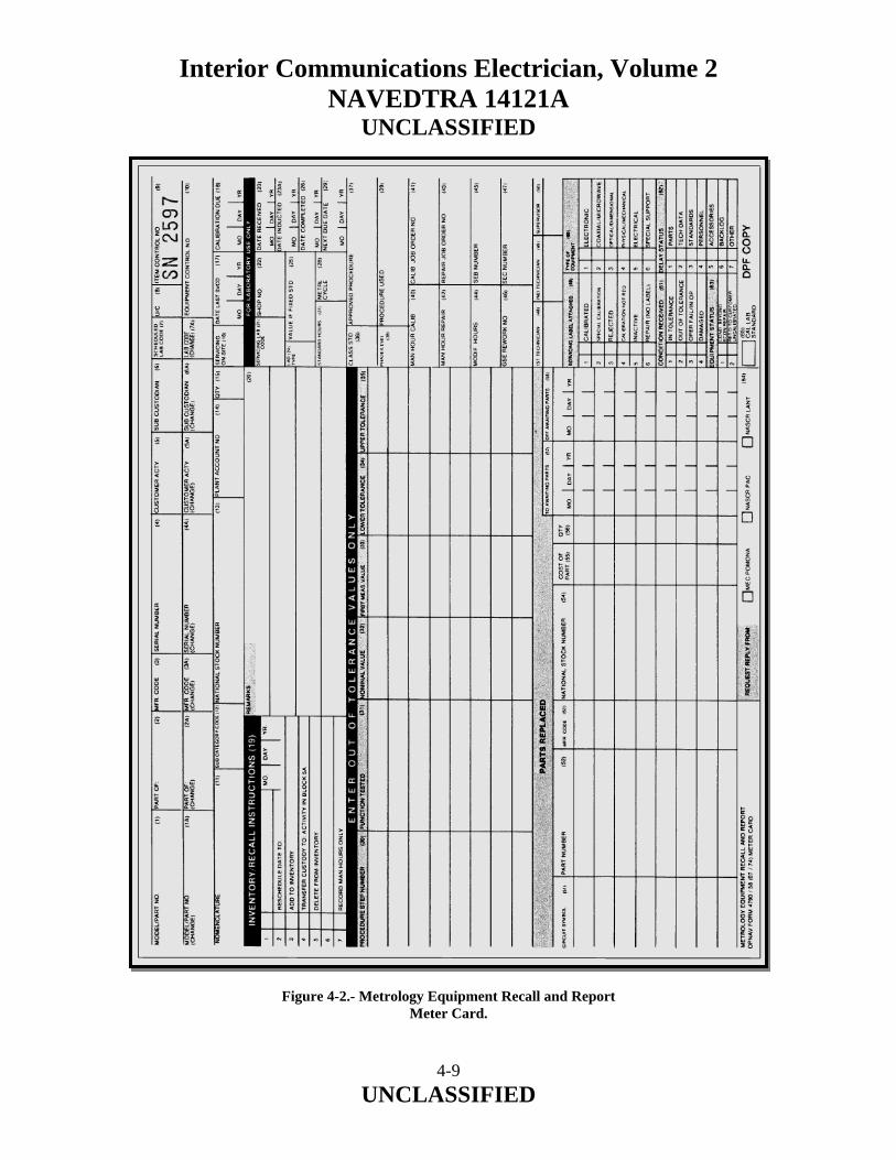
Interior Communications Electrician, Volume 2 NAVEDTRA 14121A
UNCLASSIFIED
Figure 4-2.- Metrology Equipment Recall and Report Meter Card.
4-9 UNCLASSIFIED

Interior Communications Electrician, Volume 2 NAVEDTRA 14121A
UNCLASSIFIED This card is used to record a calibration action, to add or delete equipment in the inventory, to reschedule equipment for calibration at other than the prescribed time, to transfer custody of equipment from one activity to another, or strictly to record man-hours for a completed calibration. The white copy of the completed METER card is forwarded to the MOCC where the information is keypunched into a computer to update the MEASURE data base. The new information is then printed on another METER card and sent to the customer activity to be used the next time another transaction is to be completed. Accurate data, completeness, and legibility in filling out the METER card are essential. 4.5.3 Equipment Identification and Receipt Tag The receipt and identification tag, attached to the METER card, bears the same control number as the METER card. Like the METER card, it is a five-part, color-coded form. Blocks A, B, C, D, and E of this form contain the same information that is contained in blocks 1, 3, 4, 9, and 11 of the METER card. This information is used to identify the equipment being calibrated. Both block T of the ID tag and block 5 of the METER card identify the customer; however, this information is abbreviated on the METER card. One copy of the ID tag is given to the customer as a receipt. The other four copies are kept by the calibrating facility. Unlike the METER card, no part of the ID tag is sent to the MOCC. The MOCC automatically enters this information when it preprints the METER card. 4.5.4 Measure Referral Card The MEASURE referral card is used to forward questions, recommendations, and comments pertaining to MEASURE to concerned authorities. Instructions regarding the preparation of the referral card are found in the Measure Users Manual. 4.6.0 CALIBRATION CATEGORIES When you are updating equipment calibration schedules, you need to know the calibration status of the equipment. Every item should have a label affixed to it that indicates the calibration status of that item. All labels must be attached in a conspicuous place, so as to be readily seen by all interested persons, and all tags must remain attached to the instruments as long as the information on the tag is pertinent. In the following sections we will discuss the labels and the tags, and the criteria for their use.
4-10 UNCLASSIFIED

Interior Communications Electrician, Volume 2 NAVEDTRA 14121A
UNCLASSIFIED 4.6.1 Calibrated This label (black lettering, white background), which comes in three different sizes, is the most commonly used label in the METCAL program. It indicates that an instrument is within its applicable tolerance on all parameters. 4.6.2 Calibrated – Refer to Report This label (red lettering, white background), which comes in two sizes, is used when actual measurement values and associated uncertainties must be known for the instrument to be used. 4.6.3 Special Calibration There are two Special Calibration labels (black lettering, yellow background). They differ in size and content. There is also a Special Calibration tag that is used with the smaller of the two labels. The Special Calibration label is used when some unusual or special condition in the calibration should be known to the user and/or the calibrator. These special conditions may be deviations from usual calibration tolerances, multiple calibration intervals, or requirements for in-place calibration. All conditions requiring special calibration are described either directly on the large label, or on the tag, when the small label is used. The following information amplifies these special calibrations. 4.6.4 User Calibration Some TAMS may be calibrated by the user and the instrument does not need to be sent to a calibration facility. For example, some instruments are provided with their own standards and must be calibrated either each time they are used or very frequently. Some instruments, such as oscillographic recorders, may require calibration before, during, and after each use. Some automatic test equipments require self-calibration tests to be performed each time they are used. Still other instruments are calibrated as part of checkout procedures performed daily or weekly. The requirement for calibration by the user and the calibration interval (each Use, daily, weekly, every 100 hours, each overhaul, and so on) is indicated in the METRL. The User Calibration label (black lettering, white background) must be used when the calibration is performed by the user. This label is not replaced at each calibration. When the label is first affixed to the instrument, a notation is made about the appropriate calibration interval. Records of calibrations performed, when other than each time used, are maintained in conformance with normal maintenance practices; that is, maintenance log and maintenance action form.
4-11 UNCLASSIFIED

Interior Communications Electrician, Volume 2 NAVEDTRA 14121A
UNCLASSIFIED 4.6.5 Inactive If an individual instrument due for recalibration is not expected to be used for some time in the future, recalibration may be indefinitely postponed by affixing an Inactive label (green lettering, white background) to the instrument. The Inactive label must remain on the instrument until the instrument is recalibrated, and the instrument will NOT be used while bearing the Inactive label. It must be calibrated before it can be used. 4.6.6 Calibration Not Required Standards and TAMS not requiring calibration are shown as NCR in the METRL. The No Calibration Required label (orange lettering, white background) is affixed to and should remain on the instrument until its calibration requirements change. When an instrument is not listed in the METRL as NCR, the following criteria must be used for placing the instrument in the No Calibration Required category:
1. The instrument does not make quantitative measurements nor does it provide quantified outputs. 2. The device is “fail-safe” in that any operation beyond specified tolerances will be apparent to the user. 3. All measurement/stimulus circuits are either monitored by calibrated instruments during their use or are dependent on external, known or calibrated, sources for performance within required limits.
When it is determined that an instrument falls into the Calibration Not Required category, the label is annotated as to the authority on which the decision was based, such as METRL, technical manual, letter, or message from higher authority. In the case of instruments that normally require periodic calibration but are not used to perform quantitative measurements, the label should bear the notation “Not used for quantitative measurements.”
4-12 UNCLASSIFIED

Interior Communications Electrician, Volume 2 NAVEDTRA 14121A
UNCLASSIFIED 4.6.7 Rejected In the event an instrument fails to meet the acceptance criteria during calibration and cannot be adequately repaired, a Rejected label (black lettering, red background) must be placed on the instrument. All other servicing labels must be removed. In addition to the Rejected label, a Rejected tag giving the reason for rejection and any other pertinent information is affixed to the instrument. The Rejected label and tag remain on the instrument until it is repaired and recalibrated. The instrument MUST NOT be used while bearing a Rejected label. 4.6.8 Calibration Void if Seal Broken This label (black lettering, white background) is placed over readily accessible (usually exterior) adjustments to prevent tampering by the user when such tampering could affect the calibration. The label must not cover any adjustments or controls that are part of the normal use and operation of the instrument. This label is also used to prevent removal and/or interchange of plug-in modules, subassemblies, and so on, when such removal or interchange can affect the calibration. 4.7.0 WATCH STANDING Shipboard personnel stand a variety of watches, all important to the ship and to the ship’s company. In particular, your personnel stand the IC and gyro room, telephone switchboard, damage control central, and sounding and security watches. The IC and gyro room watch is long and usually uneventful until a gyro alarm sounds or until the electrical supply is shifted. At this time, the person on watch must be alert. There are always minor repairs needed, such as to sound-powered telephones, which can be used to keep the person alert, but “skylarking” should be outlawed. The telephone switchboard operator should be well indoctrinated, and then periodically checked to make sure he/she is rendering good service to the ship. Personal calls require specific permission, and your operator should require adherence to regulations in this regard. The damage control central and sounding and security watches are independent watches and are under limited supervision. You should make sure your personnel are performing their watch standing duties properly and alertly. When problems occur, take immediate action. Only through careful counseling, adequate instructions, and periodic checks can you assure the watch standing of your personnel.
4-13 UNCLASSIFIED

Interior Communications Electrician, Volume 2 NAVEDTRA 14121A
UNCLASSIFIED The usual means of training watch standers is by an apprentice program where the person stands watches under instruction and supervision until he/she is qualified to do the job on his/her own. Whether or not the person is qualified depends on the judgment of the person assigned to instruct and supervise him/her. This system is not always dependable for the following reasons:
1. The person in training may learn bad practices as well as good from the instructor. This problem can be partially remedied by rotating the person’s watch so he/she receives indoctrination from more than one watch stander. 2. A person can stand numerous watches without experiencing a casualty, and without being exposed, through simulation, to all the possible casualties the watch stander may experience.
By recognizing the potential for these problems you can compensate for them by preparing watch-station qualification check-off sheets and by supervising the indoctrination of watch standers to the extent necessary to ensure that they become fully qualified. By these means you can be sure that the in-service training of watch standers is delivering the qualified personnel that you need. 4.8.0 SECURITY TRAINING As a supervisor, you will have responsibilities in the security area, both in safeguarding information you possess and in indoctrinating your personnel in proper procedures for handling classified information. Your security training responsibilities are part of an overall security, orientation, education, and training program that is the responsibility of your commanding officer and directed to all hands. The object of security training is to develop in all hands a sense of personal responsibility for protecting classified information and equipment. This training is done either through use of group lessons, using lectures and films, or by having personnel study the Information Security Program Regulation Manual, OPNAV Instruction 5510.1H, or other printed information on security. In and near areas where classified material is used and stored, posters are placed to remind personnel of their duties in respect to security. The following list contains some of the things personnel should be taught about security:
4-14 UNCLASSIFIED

Interior Communications Electrician, Volume 2 NAVEDTRA 14121A
UNCLASSIFIED
• Their responsibilities for security
• The importance of security and the penalties for violating security regulations
• The techniques used by foreign intelligence agents and agencies
• Their responsibilities for reporting any attempt or suspected attempt of foreign intelligence activities to gain U.S. defense information
Any IC personnel having duties in a telephone exchange should be aware that although interior communications within a ship are fairly secure, once telephone conversations get to the beach, they are very easily intercepted by taps on land lines and interceptions of microwave telephone transmissions. As part of security training, personnel having access to classified information should be briefed periodically. The following points should be emphasized:
1. Divulge classified information only to personnel who have the necessary security clearance and who must have the information to perform their official duties. 2. Personnel who have classified information have the responsibility for protecting it. 3. Personnel must be alert and ready to defend themselves against any possible espionage or subversion. 4. Discussing any classified information over a telephone is prohibited.
In addition to routine briefings, personnel who have access to classified information should be briefed before traveling to or through communist countries where there may be an attempt to subvert, or obtain, information from them. If any of your subordinates have close relatives living in communist controlled countries, they should receive a special briefing, which your command will arrange.
4-15 UNCLASSIFIED

Interior Communications Electrician, Volume 2 NAVEDTRA 14121A
UNCLASSIFIED 4.9.0 TEAM TRAINING The following procedure, recommended for training a team and its members, is especially applicable to engineering casualty control training:
1. Analyze the duties of each person in the team. 2. Permit the team (or individual) to perform a rehearsal or “dry run” of the operation slowly and without pressure. 3. Drill for greater speed and accuracy. Emphasize correct procedures in early drills and increase emphasis on speed as drills progress. 4. Allow the team (or individual) to perform the actual operation. 5. Evaluate and discuss the performance with your personnel.
4.10.0 PERSONNEL QUALIFICATIONS STANDARDS The Personnel Qualification Standards (PQS) program is another element in the Navy’s overall training program. It is used to help develop in personnel the skills necessary to perform their assigned duties. The Personnel Qualification Standard (PQS) Management Guide, NAVEDTRA 43100-1D, provides information on the PQS concept and describes its implementation into the training program of operational units of the Navy. The purpose of the program is to assist in qualifying trainees to perform their duties. It is recommended that trainees carry their qualification cards with them so they can take advantage of training “targets of opportunity” that may occur during their daily routine. Individuals are allowed to progress at a pace that fits their individual learning ability. This progress, of course, is contingent upon time periods established by department heads and division officers. Although designed for a different purpose, the PQS program helps to prepare personnel for advancement. When studying theory questions, trainees are referred to applicable training manuals and other sources of information. To determine what equipment or watch station is in the PQS program and to obtain the stock number for a particular PQS booklet, refer to NAVSUP 2002 or CNET Notice 3500.
4-16 UNCLASSIFIED

Interior Communications Electrician, Volume 2 NAVEDTRA 14121A
UNCLASSIFIED Each qualification standard has four main sub-divisions in addition to a preface, introduction, glossary, bibliography, and feedback form. These subdivisions are as follows:
100 Series—Theory 200 Series—System 300 Series—Watchstations (duties, assignments, or responsibilities) 400 Series—Qualification cards
The introduction explains the use of the qualification standard in terms of what it will mean to the user as well as how to apply it. The theory (100 series) section specifies the knowledge of theory necessary as a prerequisite to the study of the specific equipment or system for which the PQS was written. The system (200 series) section breaks down the equipment or systems to be studied into functional sections. PQS items are constructed as clear, concise statements/questions according to a standard format. The answers must be extracted from the various manuals covering the equipment or systems for which the PQS is written. This section asks the user to explain the function of the system, to draw a simplified version of the system from memory, and to use this drawn schematic or the schematic provided in the maintenance manual while studying the system or equipment. Emphasis is given to such areas as maintenance management procedures, components, component parts, principles of operation, system interrelations, numerical values considered necessary to operation and maintenance, and safety precautions. A study of the items in the system section provides the individual with the required information concerning what the system or equipment does, how it does it, and other pertinent aspects of operation. The watch stations (300 series) section includes questions regarding the procedures the individual must know to operate and maintain the equipment or system. In this section, the questions advance the qualification process by requiring answers or demonstrations showing the ability to use the knowledge covered in the system section and to maintain the system or equipment.
4-17 UNCLASSIFIED

Interior Communications Electrician, Volume 2 NAVEDTRA 14121A
UNCLASSIFIED Areas covered include normal operation; abnormal or emergency operation; emergency procedures that could limit damage and/or casualties associated with a particular operation; operations that occur too frequently to be considered mandatory performance items; and maintenance procedures/instructions such as checks, tests, repairs, replacements, and so on. The qualification cards (400 series) section covers the accounting documents used to record the individual’s satisfactory completion of items. A complete PQS package should be given to each person being qualified so he or she can use it at every opportunity to become fully qualified in all areas of the appropriate rating and the equipment, system, or watch station for which the PQS was written. At what point to begin a PQS booklet will depend on the individual’s assignment within an activity. Upon transfer to a different activity, each individual usually must requalify. As a Petty Officer Second Class, you will be able to use the required watch station PQS to help train the personnel assigned to your watch section. It will also give you a way of documenting the progress of each person in qualifying as an IC Electrician watch stander. 4.11.0 SAFETY Safety is the responsibility of all personnel. Personnel injury or death due to electric shock and damage to equipment require that all personnel adhere strictly to applicable safety precautions. With electrical and electronic equipment, safety violations could result in immediate equipment damage and severe personnel injury. If you are in doubt about applicable electrical or electronic safety precautions, refer to NSTM, chapters 300 and 400, the Standard Organization and Regulations of the U.S. Navy (SORM), ONNAVINST 3120.32B, and NAVOSH Program Manual for Forces Afloat, OPNAVINST 5100.19B. Remember, safety is paramount! 4.11.1 Safety Responsibilities U.S. Navy Regulations, Commanding Officer shall article 0712 states: “The require that all persons concerned are instructed and drilled inapplicable safety precautions and procedures, that these are complied with, and that the applicable safety precautions, or extracts there from, are posted in appropriate places, In any instance where safety precautions have not been issued, or are incomplete, he shall issue or augment such safety precautions as he deems necessary, notifying, when appropriate, higher authorities concerned.”
4-18 UNCLASSIFIED

Interior Communications Electrician, Volume 2 NAVEDTRA 14121A
UNCLASSIFIED Navy Regulations also spells out specific responsibilities of the executive officer, engineer officer, division officer, and engineering officer of the watch. These regulations are intended to make safety a prime responsibility of supervisors. Commanding officers cannot delegate their safety responsibilities, but they can delegate their authority to officers and petty officers to ensure safety precautions are understood and enforced. As a supervisor, you must be aware of the safety of personnel and ensure they receive the necessary training and information in regards to safety. The most important step in maintaining safe working conditions is a thorough indoctrination of all personnel. For example, when new safety posters or precautions are received, supervisors are responsible for interpreting the messages correctly. In this way, they will ensure all personnel interpret and observe the approved safety rules and procedures correctly. It is essential that all repair and maintenance work be accomplished without personnel injury or damage to equipment. 4.11.2 Enforcing Safety Safety precautions, as all rules, laws, or regulations, should be enforced. It is your duty to take appropriate action any time you see any person disregarding a safety precaution. You should require that all jobs be done according to applicable safety precautions. Doing a job the safe way in some cases may take a little longer or may be a little more inconvenient; however, there is no doubt as to the importance of doing it this way. 4.11.3 Safe Electrical/Electronic Maintenance Electrical/electronic maintenance is, to some extent, hazardous due to the nature of the work. Safety must rank as a prime concern because of the inherent danger of electrical shock. EFFECTS OF ELECTRICITY.— The factors that determine whether you receive a slight or fatal shock are (1) the amount and duration of current flow, (2) the parts of the body involved, and (3) the frequency of the current if it is ac. Generally, the greater the current flow and the length of time one is subjected to it will determine the damage done. The extent of the current through you to vital nerve centers and organs may determine whether or not you survive the electric shock. The frequency of the current is also a determining factor, with 60- and 400-Hz current flow being more dangerous than dc.
4-19 UNCLASSIFIED

Interior Communications Electrician, Volume 2 NAVEDTRA 14121A
UNCLASSIFIED The ability to resist an electrical shock will vary from person to person and day to day. The Naval Sea Systems Command (NAVSEA) has summarized the relationship of current magnitude to degree of shock:
1. At about 1 milliamp (0.001 ampere), shock is perceptible. 2. At about 10 milliamps (0.01 ampere), shock is sufficient to prevent voluntary control of muscles. 3. At about 100 milliamps (0.1 ampere), usually fatal if it lasts for 1 second or more.
SAFE PRACTICES.— When working on electrical or electronic circuits, you must observe applicable safety precautions and follow approved procedures. These precautions should be scrupulously followed by both yourself and the person working with you.
1. Electrical and electronic circuits often have more than one source of power. Take time to study the schematics or wiring diagrams of the entire system to ensure that all power sources are secured and tagged out. 2. If pertinent, inform the remote station regarding the circuit on which work will be performed. 3. Use one hand when you turn switches on or off. Keep the doors to switch and fuse boxes closed, except when working inside or replacing fuses. 4. After frost making certain that the circuit is dead, use a fuse puller to remove cartridge fuses. 5. All supply switches or cutout switches from which power could possibly be fed should be secured in the off or open (safety) position and tagged with a red danger tag (NAVSHIPS 9890/S(REV)).
6. Keep clothing, hands, and feet dry if at all possible. When it is necessary to work in wet or damp locations, use a dry steady platform to sit or stand on, and place a rubber mat or other nonconductive material on top of the platform. Use insulated tools and insulated flashlights of the molded type when required to work on exposed parts. In all instances, repairs on energized circuits must be made with the primary power not applied except in case of emergency, and then only after specific approval has been given by the commanding officer. When approval has been obtained to work on equipment with the power applied, keep one hand free at all times (behind you or in your pocket).
4-20 UNCLASSIFIED

Interior Communications Electrician, Volume 2 NAVEDTRA 14121A
UNCLASSIFIED
7. Never short out, tamper with, or block open an interlock switch. 8. Keep clear of exposed equipment; when it is necessary to work on it, wear approved, tested rubber gloves and work with one hand as much as possible. 9. Avoid reaching into enclosures except when absolutely necessary; when reaching into an enclosure, use rubber gloves to prevent accidental contact with the enclosure. 10. Make certain that equipment is properly grounded. 11. Turn off the power before connecting alligator clips to any circuit.
12. Never use your finger to test a “hot” line. Use approved meters or other indicating devices.
It is the responsibility of every person connected with equipment maintenance to discover and eliminate unsafe work practices. 4.11.4 Sources of Safety Information Included among the available sources of safety information are directives, instructions, and notices issued by the Chief of Naval Operations, the NSTMs, manufacturers’ technical manuals, safety notices, and bulletins published periodically. SAFETY DIRECTIVES AND PRECAUTIONS.— The items in the various safety directives and publications are designed to cover usual conditions in naval activities. Commanding officers and others in authority are authorized and encouraged to issue special precautions to their commands to cover local conditions and unusual circumstances. Guidance for the promotion of accident prevention aboard ship is contained in the Navy Occupational Safety and Health (NAVOSH) Program Manual for Forces Afloat, OPNAVINST 5100.19B, and the Navy Occupational Safety and Health (NAVOSH) Program Manual, OPNAVINST 5100.23G. Safety directives and precautions should be followed to the letter in their specific application. Should any occasion arise in which any doubt exists as to the application of a particular directive or precaution, the measures to be taken are those which will achieve maximum safety. The safety officer is available to assist in interpreting and suggesting ways of implementing safety directives and precautions.
4-21 UNCLASSIFIED

Interior Communications Electrician, Volume 2 NAVEDTRA 14121A
UNCLASSIFIED NAVAL SHIPS’ TECHNICAL MANUAL.— Chapter 300, “The Electrical Plant General,” gives clear and concise electrical safety precautions that should be “required study material for all hands.” Although some areas may need explanation to nonrated personnel, many items of common sense are stressed. This material should be included in the training of all personnel, with heavy emphasis placed on the correct procedure for artificial respiration. Other chapters of the NSTM, including chapter 430, “Interior Communications,” give specific precautions related to specific areas. MANUFACTURERS’ TECHNICAL MANUALS.— Applicable safety precautions are written in all equipment technical manuals. Generally speaking, most training underscores the Principle of Operation and the Maintenance sections of these manuals, yet fails to place proper emphasis on safety items. Often the precautions are located in the front of the manual before the table of contents, where they are easily overlooked. Senior petty officers should ensure that each person sent out on a maintenance action is instructed on the precautions to be observed. Too often high voltage sources and alternate power sources mentioned in the Safety section of the technical manual are overlooked or forgotten by junior electricians until the screwdriver is in place. MAINTENANCE REQUIREMENT CARDS.— Each maintenance requirement card (MRC) used in the Navy has a section devoted to safety precautions to be observed by the person who performs the maintenance action prescribed on the card. Sometimes, this section contains only a reminder to observe standard safety precautions. But, whatever they are, the leading petty officer responsible for the maintenance action should ensure that each person in his/her work group is instructed in the safety precautions and observes them while performing his/her tasks. PERIODICALS.— Many sources of safety information are distributed on a monthly or quarterly basis by various naval activities. The Naval Safety Center publishes the Ships Safety Bulletin and Fathom, a quarterly surface ship and submarine safety review. Fathom presents accurate and current information on the subject of nautical accident prevention. Safety Review, published monthly by the Chief of Naval Material (CHNAVMAT), contains information on the safe storage, handling, or other use of products and materials. Articles dealing with safety appear often in Electronics Information Bulletin, Deckplate, and Surface Warfare magazine.
4-22 UNCLASSIFIED

Interior Communications Electrician, Volume 2 NAVEDTRA 14121A
UNCLASSIFIED Fire Safety The best way to control any fire is not let it happen. When working on equipment, personnel should always be aware that circuit protective devices, such as fuses and circuit breakers, are frost-line insurance against overheating and must be in good condition. The filter is an important part of filtered ventilating systems. If the filter is clogged, the equipment will run hot and may bum out. If the filter is not in place or has holes in it, dust will get into the system and present a possible fire hazard. When falters are replaced, the replacement filter must be the same type as the original. When equipment is opened, components and wiring insulation should be inspected for signs of overheating. To avoid dangerous short circuits, electrical insulation must be of the correct type and in good condition. In addition to ensuring good performance and long equipment service life, careful workmanship will help prevent fires. A badly made connection that vibrates loose or a conductor that carries high voltages too close to another can cause an arc. Pulling fuses on energized circuits should be avoided since an arc can result. When it comes to fire prevention, the fewer sparks the better. If a fire or overheated condition occurs in electrical equipment, the circuit should be de-energized as quickly as possible. Carbon dioxide (CO2) is to be used in fighting electrical fires because it is nonconductive and thereby the safest to use in terms of personnel safety, and because it offers the least likelihood of doing equipment damage. However, if the discharge horn is allowed to touch an energized circuit, the horn may transmit a shock to the handler, due to frost on the horn. Outside Safety IC Electricians perform maintenance on equipment located throughout the ship. A leading petty officer may have personnel working simultaneously on the bridge, in the engine room and fireroom, and in several other spaces. It is imperative that all of these personnel be aware of the general and specific safety precautions involved in their work. The person who neglects to secure the power to the salinity system (circuit SB) when cleaning it is just as likely to be injured or killed as the one who doesn’t properly use a safety harness when aligning the anemometer (circuits HD, HE).
4-23 UNCLASSIFIED

Interior Communications Electrician, Volume 2 NAVEDTRA 14121A
UNCLASSIFIED Live Circuits More often than not, it is impossible to align de-energized equipment. Gyro repeaters, engine order telegraphs, and other synchro systems require adjustment “hot”; therefore, several precautions must be observed whenever the work is being done on energized electrical equipment.
1. Provide ample illumination. 2. Do not wear a wrist watch, rings, watch chain, metal articles, or loose clothing that might make accidental contact with live parts or that might accidentally catch and throw some part of the body into contact with live parts. Clothing and shoes should be as dry as possible. 3. Insulate the worker from ground by means of insulating material covering any adjacent grounded metal with which he/she might come in contact. Suitable insulating materials are rubber mats, dry canvas, dry phenolic material, or even heavy dry paper in several thicknesses. Be sure any such insulating material is dry, has no holes in it, and has no conducting materials embedded in it. Cover sufficient areas so adequate latitude is permitted for movement by the worker in doing the work. 4. Use insulated hand tools. 5. Insofar as practicable, provide insulating barriers between the work and any live metal parts immediately adjacent to the work to be done. 6. Use only one hand in accomplishing the work if practical. Wear a rubber glove on the hand not used for handling tools. If the work being done permits, wear rubber gloves on both hands. 7. Have personnel stationed by circuit breakers or switches, and telephone manned if necessary, so the circuit can be de-energized immediately in case of emergency. 8. Have immediately available a person qualified in mouth-to-mouth respiration and cardiac massage for electric shock.
4-24 UNCLASSIFIED

Interior Communications Electrician, Volume 2 NAVEDTRA 14121A
UNCLASSIFIED Tagging Procedure For many years the Navy has recognized the value of tagging circuits upon which personnel are working, but a good tagging procedure is worthless unless it is backed up by the petty officers in charge. Often junior personnel tend to take tags lightly—a tendency that could prove fatal. Then too, there have been cases where personnel have long since left the ship and the tags they installed remain in place. When this happens, the entire circuit must be checked for grounds and shock hazards before the tags are removed and the circuit energized. Recently there has been a tendency to supply power to certain nonvital circuits, such as the wardroom buzzer system, from local lighting panels. Since power is taken from a lighting panel, the repairing IC Electrician must tag the circuit using a red danger tag before working on it. If more than one repairman is engaged in repairing apiece of equipment, each person should tag the circuit and, upon completion of work, each should remove his/her own tag. Working Aloft When radio or radar antennas are energized by transmitters, workers must not go aloft until steps have been taken to ensure that no danger exists. A casualty can occur from even a small spark drawn from a charged piece of metal or rigging. Although the spark itself may be harmless, the “surprise” may cause the worker to let go his grasp involuntarily. There is also shock hazard if nearby antennas are energized, such as those on stations ashore or aboard a ship moored alongside or across a pier. Danger also exists from rotating antennas that might cause personnel working aloft to fall by knocking them from their perch. Motor safety switches controlling the motion of antennas must be tagged and locked open before anyone is allowed aloft close to such antennas. Personnel working near a stack must wear the recommended oxygen breathing apparatus. Among other toxic substances, stack gas contains carbon monoxide. Carbon monoxide is too unstable to buildup to a high concentration in the open, but prolonged exposure to even small quantities is dangerous. Each time a person goes aloft to work he/she must follow established procedures listed here:
4-25 UNCLASSIFIED

Interior Communications Electrician, Volume 2 NAVEDTRA 14121A
UNCLASSIFIED
1. Get permission of the communications watch officer (CWO) and the OOD. 2. Check with the engineer officer to ensure that the boiler safety valves are not being set. 3. Get the assistance of another person along with a ship’s Boatswain’s Mate who is qualified in rigging. 4. Wear a safety harness. To be of any benefit, the best harness must be fastened securely as soon as the place of work is reached. Some workers had complained on occasion that a safety harness is clumsy and interferes with movement. True as this maybe, it is also true that a fall from the height of an antenna is usually fatal. 5. Keep both hands free for climbing. Tools are not to be carried in hand; an assistant can lift them to the work site. 6. Secure tools with preventer lines to keep them from dropping on a shipmate. 7. Keep a good footing and firm grasp at all times. The nautical expression HOLD FAST serves as a good memory device, in case one is needed.
Shore Connections The connection of the ship’s service telephone system to a shore exchange is a frequent evolution carried out by junior IC Electricians. There are two possible hazards: the 48-volt dc power supply and the 90-volt ring current used in telephones. Any hazard due to the ship’s telephones can be avoided by keeping the manual switchboard de-energized during connection. In making the shore connection, the IC Electrician must assume the circuit is energized (as is the practice in some ports) and act accordingly. Connection at some piers is made by plug-in-type plugs and the hazards are minimized; however, where lug and screw connections are made, emphasis must be placed on live circuit precautions. On many ships, IC Electricians assist in connecting and disconnecting ship’s service power to shore power.
4-26 UNCLASSIFIED

Interior Communications Electrician, Volume 2 NAVEDTRA 14121A
UNCLASSIFIED IC Room Safety Since a major portion of the IC Electrician’s time is spent working in the IC room or IC workshop, it is important that supervisory personnel examine the personnel hazards present in these areas. It is mandatory, of course, that the area be initially laid out with the proper rubber matting and that the workbench and test switchboard be installed with maximum safety for personnel as a prime consideration. Maintenance and Repair As an IC Electrician Second Class, you will be expected to supervise and train personnel when standing watch. Most commands have a trouble-call log in either DC central or in the IC/gyro room. There is usually one to three personnel on watch in the IC/gyro room depending on the size of the command. If not, there is always someone with the duty of responding to casualties when they occur. You, as a supervisor, will be expected to train your watch personnel on how to respond to these calls and the hazards they may encounter. SWITCHBOARDS AND ENCLOSED EQUIPMENT.— The hazards involved to the operator and the repairman regarding switchboards have been greatly reduced in recent years by the installation of dead-front service-type switchboards. These and other enclosed equipments, however, require specific care in servicing and cleaning. Switches should be operated with the safety of both the operator and other personnel in mind. Before closing any switch, be sure the circuit is ready in all respects to be energized. Make sure all personnel working on the circuit are notified that it is to be energized. When operating circuit breakers or switches, use only one hand if possible. Use judgment in replacing blown fuses. Only fuses of 10 ampere capacity or less should be removed or replaced in energized circuits. Fuses larger than 10 ampere ratings should be removed or replaced only when the circuit is de-energized. Do not work on any energized circuit, switchboard or other piece of electrical equipment unless absolutely necessary. Do not undertake any work on energized switchboards without first obtaining the approval of the commanding officer. When you have received permission to work on a live circuit, DO NOT attempt to do so by yourself; have another person (safety observer), qualified in first aid for electrical shock, present at all times. The person stationed nearby should also know the circuits and the location of switches controlling the equipment and should be given instructions to pull the switch immediately if anything unforeseen happens. The worker within the enclosure must always be aware of the nearness of other live circuits. Use rubber gloves where applicable and stand on approved rubber matting.
4-27 UNCLASSIFIED

Interior Communications Electrician, Volume 2 NAVEDTRA 14121A
UNCLASSIFIED Circuits or equipment to be worked on should be de-energized by opening all switches through which power could be supplied and then testing the circuit with a voltmeter or voltage tester. These switches should then be tagged with danger tags. In case more than one party is engaged in repair work on a circuit, a danger tag for each party should be placed on the supply switches. A cardinal, yet often violated, rule regarding enclosed equipment is never override or disable an interlock. The Navy designed the interlock in the circuit and no one should be allowed to violate it. Dirt, dust, lint, and excessive oil must be removed from IC equipment. Junior personnel should, before they begin a cleaning evolution, be instructed in and take adequate precautions for their safety. Two general cleaning rules are as follows:
1. Loose dust and dirt should be removed with a vacuum cleaner or clean rags. Low-pressure compressed air may be used provided the air is free of foreign particles and moisture. Normal ship’s service air is 100 psi and must be reduced to approximate y 30 psi before it is used. 2. Oil or hard dirt may require a cloth dampened with inhibited methyl chloroform for adequate cleaning. Extreme care must be used on steel and varnish.
IN-SHOP REPAIRS.— Many repairs made in the IC room involve equipment normally used in other parts of the ship. To make these repairs, it is often necessary to use hand and portable electric tools. Safe Practices for Hand Tools.— Normally, you should have no problems when working with hand tools. In all likelihood, however, you have seen some dangerous practices in the use of hand tools that should have been avoided. One unsafe practice involves the use of tools with plastic or wooden handles that are cracked, chipped, broken, or otherwise unserviceable. This practice is sure to result in accidents and personnel injuries, such as cuts, bruises, and foreign objects being thrown in the eyes. If these unserviceable tools are not repairable, discard or replace them. Safety with Portable Electric Tools.— Portable electric tools should be clean, properly oiled, and in good repair. Before they are used, inspect the tool for proper grounding. The newer double insulated, plastic case tools have a two-conductor cord and a two-prong plug.
4-28 UNCLASSIFIED

Interior Communications Electrician, Volume 2 NAVEDTRA 14121A
UNCLASSIFIED If a tool is equipped with a three-prong plug, it should be plugged into a grounded-type electrical outlet. Never remove the third prong from the plug. Make absolutely sure the tool is properly grounded according to NSTM, chapter 300. Observe safety precautions and wear rubber gloves when plugging in and operating portable electric tools under particularly hazardous conditions. Examples of particularly hazardous conditions are wet decks, bilge areas, or working over the side in rafts or boats. Before issuance of any portable electrical equipment, the attached cable with plug (including extension cords, when used) should be examined visually to assure it is in satisfactory condition. (Tears, chafing, exposed insulated conductors, and damaged plugs are causes for cable or plug replacement.) Any portable electrical equipment with its associated extension cords should be tested before to issue with an approved tool tester or plugged into a dummy (or de-energized) receptacle and tested for resistance from equipment housing to ship’s structure with an ohmmeter (the resistance of the grounding circuit must be less than 1 ohm). Move or work the cable with a bending or twisting motion. A change in resistance will indicate broken strands in the grounding conductor. If this is found, replace the cable. It is further suggested that, at the discretion of the commanding officer, a list be established of portable equipment requiring testing more or less often than once a month depending on conditions in the ship. Where the Planned Maintenance System (PMS) is installed, tests should be conducted according to the MRCs. Other safe practices in the use of portable electric power tools include the following: –Inspect the tool cord and plug before using the tool. Do not use the tool if its cord is frayed or its plug is damaged or broken. Do not use spliced cables except in an emergency that warrants the risk involved. –Before using the tool, lay all portable cables out so you and others cannot trip over them. The length of extension cords used with portable tools should not exceed 25 feet. Extension cords of 100 feet are authorized on flight and hangar decks. Extension cords of 100 feet are also found in damage control lockers, but are labeled for “Emergency Use Only.” –Do not use jury-rigged extension cords that have metal “handy boxes” for receptacle ends of the cord. All extension cords must have nonconductive plugs and receptacle housings.
4-29 UNCLASSIFIED

Interior Communications Electrician, Volume 2 NAVEDTRA 14121A
UNCLASSIFIED –Connect the tool cord into the extension cord (when required) before inserting the extension cord into a live receptacle. After using the tool, unplug the extension cord (if any) from the live receptacle before unplugging the tool cord from the extension cord. Do not unplug the cords by yanking on them. –Stow the tool in its assigned place after you are through using it. Nonstandard Equipment.— The practice of having unauthorized or jury-rigged electrical equipment on board is a hazard and must be dealt with as such. The only way to ensure that jury-rigged and unauthorized equipment is not being used is for you personally to make checks for such installations. Alterations Naval regulations provide that no alterations are permitted to be made to ships until authorized by NAVSEA. Some of the reasons for this regulation that are particularly applicable to IC systems are as follows:
1. NAVSEA is responsible for the design and maintenance of IC systems in all naval ships. Therefore, it is necessary that NAVSEA have accurate information as to all existing installations. 2. In the interests of standardization, it is necessary that all requests for alterations be forwarded to NAVSEA so the alteration may be authorized for all ships in which similar conditions exist. 3. In the interests of conserving funds, NAVSEA weighs the importance and necessity of all alterations so available funds may be most wisely used.
4. Many alterations that seem desirable to the ships may have unsuspected defects or disadvantages not immediately apparent to ship’s personnel. In this respect NAVSEA acts as a clearing house for information from numerous sources, including other bureaus and offices of the Naval Establishment.
Electric Shock As an IC Electrician, you will be working in areas and on equipment that pose a serious shock hazard. If you always follow the safety precautions outlined earlier, you can minimize the risk. But remember, the possibility of electric shock is always present. If you are at the scene of an accident, you will be expected to help the victim as soon as possible. Additional information on watch standing and safety can be found in Basic Military Requirements, NAVEDTRA 14325, and in the military requirements training manuals.
4-30 UNCLASSIFIED

Interior Communications Electrician, Volume 2 NAVEDTRA 14121A
UNCLASSIFIED 4.12.0 SHOP SUPERVISION As an ICI or ICC, one of your more important roles will be as a supervisor or leader. You will be responsible for planning and organizing work and supervising and directing personnel. As the IC1 or ICC in charge of an IC shop, you should fully appreciate and understand the responsibility you hold as a member of a shipboard organization and be able to identify each of your duties with respect to any assigned job. The following list includes the duties and responsibilities that are common to most shop supervisors:
• Getting the right person on the job at the right time
• Using tools and materials as economically as possible
• Preventing conditions that might cause accidents
• Maintaining discipline
• Keeping records and preparing reports
• Maintaining the quality and quantity of repair work
• Planning and scheduling repair work
• Training personnel
• Requisitioning tools, equipment, and materials
• Inspecting and maintaining tools and equipment
• Giving orders and directions
• Cooperating with others
• Checking and inspecting completed repairs
• Promoting teamwork
4-31 UNCLASSIFIED

Interior Communications Electrician, Volume 2 NAVEDTRA 14121A
UNCLASSIFIED 4.12.1 Maintenance and Repair To fulfill your administrative responsibilities in connection with and supervisory maintenance and repair, you must have the ability to plan. By following prescribed procedures of the 3-M Systems, maintenance planning should be easy. But some administrative and supervisory duties will not be affected by the 3-M Systems. You will always find some engine-room maintenance and repair work that just won’t fit into a schedule, but must be done whenever the opportunity arise. So, in addition to having the ability to plan, you must also have a certain amount of flexibility so you can alter your plans to fit the existing circumstances. A few administrative and supervisory considerations that apply to maintenance and repair are discussed in the following sections. The 3-M Systems, like any other system or program, is only as good as the personnel who make it work. Your role in the 3-M Systems, as an IC1 or ICC, will include the training of lower-rated personnel in its use. These personnel must be trained in the scheduling and supervision of maintenance. As a supervisor, you should keep abreast of all developments and changes to the 3-M Systems. Details on the 3-M Systems and changes related to it are available in the Ship’s Maintenance and Material Management (3-M) Manual, OPNAVINST 4790.4 Series. 4.12.2 Planning Careful planning is necessary to keep an IC shop running efficiently and productively. Planning results in the proper employment of your people. Today’s IC Electricians are well-trained technicians, who have the right to expect their service to be employed in an orderly fashion with proper organization and supervision. The weekly PMS work schedule is a proven method of ensuring proper personnel employment. The mechanics of the PMS system allows the supervisor to ensure that there is adequate time for training, ship’s evolutions, recreation, and so on. Most important in using PMS is the supervisor’s familiarity with the ship’s schedule on a given day. You must “get the word” so that you can plan your people’s work. Therefore, getting the word is your responsibility. The proper use of the weekly PMS work schedule will, in a short time, result in more training and less equipment downtime. Your subgroup leaders must use foresight in planning this schedule. In particular, avoid stretching your supervisory personnel too thin. A person cannot provide adequate supervision to the installation of an electromagnetic log (sword) and the removal of a wind indicator (bird) at the same time.
4-32 UNCLASSIFIED

Interior Communications Electrician, Volume 2 NAVEDTRA 14121A
UNCLASSIFIED The job cards used in the PMS system can be useful maintenance aids on any ship, provided they first are tailored to your ship via the PMS feedback report. Your particular salinity system may have one or two peculiar steps that must be taken in removing a cell. The cards are made out for a standard system, and modification is possible. Job cards do, however, give properly sequenced procedures for job performance and should be followed. Emergency planning should be done when possible in a check-off list fashion. By analyzing your needs and, where possible, writing the job out in procedural steps, you may learn many things. On jobs that affect the ship’s maneuverability, the written procedural method is particularly effective in getting the right conditions set up and help lined up. By going over the replacement of a synchro transmitter in the propeller revolution indicator circuit step by step with your division officer, you may find that you can have the shaft stopped, thus aiding in the repair of the synchro transmitter. You must ensure that all personnel are informed about the nature and scheduling of repairs. The realignment of a gyrocompass synchro amplifier may cause havoc for the ETs, FTs, STs, and OSs. However, if you inform the group supervisors ahead of time, they can act to prevent or lessen trouble in their equipment. Emergency repairs require the permission of the OOD. Your division officer should always be notified. You must remember that the IC group is not an end unto itself, but rather a member of a team. An important phase of planning your work is the organizing of your personnel to accomplish their task. This is, however, a ship-to-ship problem, with subgroup supervisors varying in technical background and subordinate personnel varying in number. It is imperative that a team spirit is developed in your personnel and that you maintain something of a competitive spirit. Through proper employment of competition, the standard of the IC group at work, at quarters, and in the compartment can be maintained above that of the other engineers. By the nature of the work involved, IC Electricians should be able to maintain their berthing spaces and their uniforms in top condition. There is often reluctance on the part of many technicians to make the change to technical supervisor. As the leading IC Electrician, you must ensure that this change takes place. You can do this by assigning part of the supervisory load to personnel who have advanced in an orderly fashion. Take care to provide up-to-date records that will help them on the new assignment. Be sure that time is allowed for them to become familiar with their new responsibility. Take them into your confidence regarding planning and professional matters.
4-33 UNCLASSIFIED

Interior Communications Electrician, Volume 2 NAVEDTRA 14121A
UNCLASSIFIED You, as a supervisor, must be available to your subgroup supervisors, and they, in turn, must be available to their subordinates. Ensure that all requests come up the line in proper fashion. Also, make sure that they go down the line in the same fashion. Avoid collecting request chits at quarters before your petty officers have a chance to consider them. Don’t let your personnel get their replies in the log room. Pick them up yourself and return them to the subgroup supervisor. This is a small item, but it reinforces the chain of command. Except when dealing with a severe personal problem, always ask subgroup supervisors to accompany any of their personnel with whom you must converse, rather than have them go it alone. This should give them confidence in their supervisor and you the benefit of the supervisor’s views. As a supervisor, you must be aware of each job as it is worked by your personnel. Show an active interest in the personnel under you. If you do not periodically check on your subordinates’ work, you will soon become aware of problems at a later time. As a supervisor, you must, while keeping your hand on the job, keep it off the screwdriver. 4.12.3 Information on Incoming Work Job orders will generally be received in the shop several days in advance. You should start planning as soon as possible to gain an advantage of time. Much of your planning may be done before the work is delivered to the work center. PRIORITY OF JOBS In planning and scheduling work you will have to give careful consideration to the priority of each job order. Priorities are generally classified as urgent, routine, and deferred. The majority of job orders will have the routine priority assigned to them. Routine jobs make up the normal workload of the work center, and they must be carefully planned and scheduled so that the daily organization and production can be maintained at a high standard. Urgent-priority jobs require immediate planning and scheduling. Lower-priority jobs may have to be set aside so that urgent jobs can be done. Deferred jobs do not present much of a problem. They are usually accomplished when the workload of the shop is light and there are few jobs to be done.
4-34 UNCLASSIFIED

Interior Communications Electrician, Volume 2 NAVEDTRA 14121A
UNCLASSIFIED When determining the priority of a task, you should consider the following information:
• The ship’s schedule and the effect the equipment will have on the ability of the ship to perform its mission
• Whether the work requires someone with special qualifications
• Whether or not all the required parts and material are available
The work center supervisor should review the work for the week with the division officer and determine the jobs that need to be accomplished right away (priority 1) and those that can be done at a later date (priority 2). The work that cannot be completed due to the lack of material or trained personnel should then be deferred to request material or outside assistance (priority 3). When work gets sent to an outside activity, you should fill out a Ship’s Maintenance Action Form, OPNAV 4790/2K (fig. 4-3). When filling out this form, you should fill out all the proper blocks as completely as possible. Refer to figure 4-3 to determine what blocks you must fill out. You must provide as much technical documentation as possible. You may have to fill out a Supplemental Form, OPNAV 4790/2L (fig. 4-4), when requirements are not covered by technical documentation. If you cannot complete a priority 1 task because of ship’s schedule or other reasons, you should work on a priority 2 task. In this manner, the shop will be able to accomplish assigned tasks in a timely and effective manner.
4-35 UNCLASSIFIED

Interior Communications Electrician, Volume 2 NAVEDTRA 14121A
UNCLASSIFIED
Figure 4-3.- Ship’s Maintenance Action Form (2-KILO).
4-36 UNCLASSIFIED
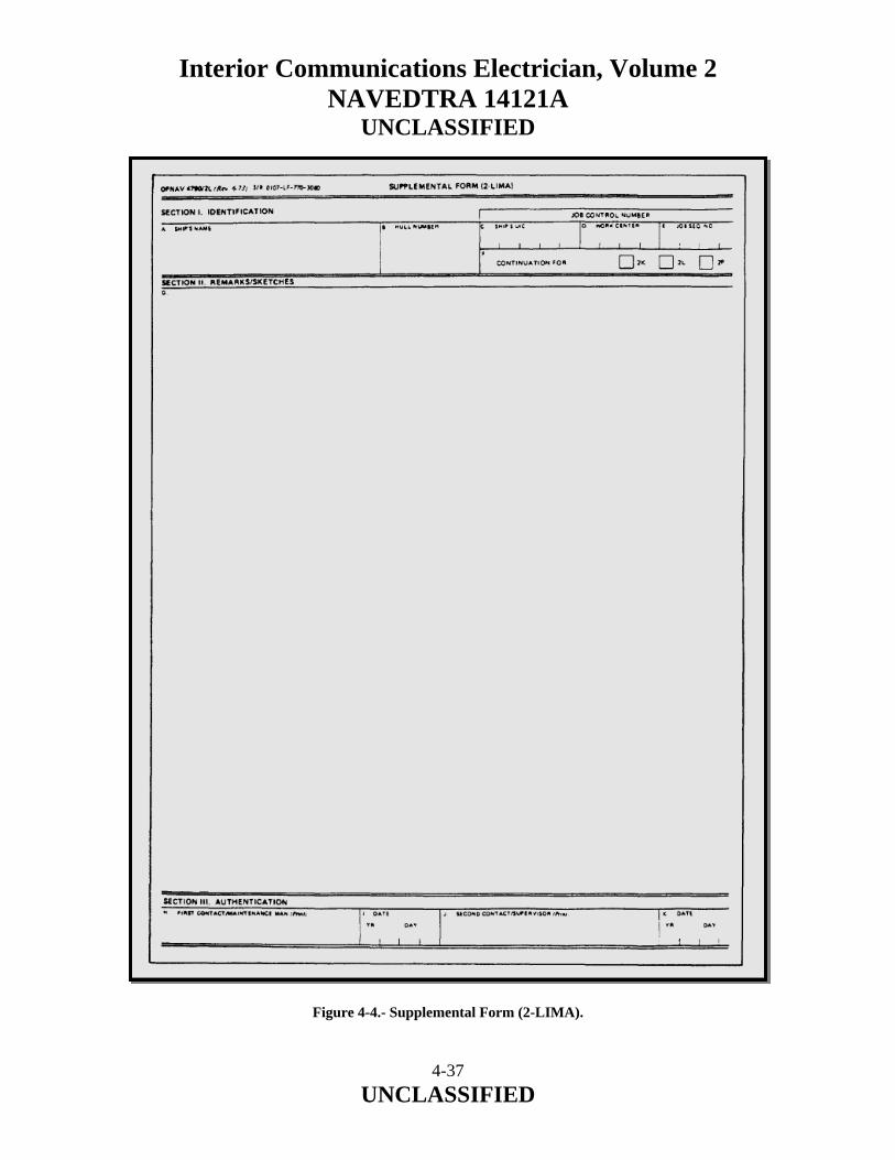
Interior Communications Electrician, Volume 2 NAVEDTRA 14121A
UNCLASSIFIED
Figure 4-4.- Supplemental Form (2-LIMA).
4-37 UNCLASSIFIED

Interior Communications Electrician, Volume 2 NAVEDTRA 14121A
UNCLASSIFIED SCHEDULING OF WORK The main object in the scheduling of work is to have the work flow smoothly and without delay, since lost time between jobs lowers the overall efficiency of the work center. Because of the variety of jobs you and your personnel will be required to perform, specific work schedules must be prepared to ensure that all work is completed. Although these schedules list specific job assignments, they must be flexible enough to allow for changes in priorities, transfer of personnel, temporary breakdowns of equipment, unscheduled ship drills, or any emergency that may arise. You may have to change the schedule of work in the work center when new high-priority jobs come in. Sometimes you may have to set other work aside temporarily y until these urgent jobs are completed. Careful planning is required to keep up with all shipboard maintenance and repair work. Some of the factors that you should consider when scheduling maintenance and repair work are as follows:
• Size up each job before you let anyone start working on it. Check the applicable maintenance requirement cards (MRCs) so that you will know exactly what needs to be done. Also, check all applicable drawings and manufacturer’s technical manuals.
• Check on materials before you start. Be sure that all required materials are
available before your personnel start working on any job. Do not overlook small items, such as nuts, bolts, washers, packing and gasket materials, tools, and measuring devices. A good deal of labor can be saved by the simple process of checking on the availability of materials before a job is actually started. An inoperable piece of equipment can become a nuisance and a safety hazard if it is spread around the room in bits and pieces while you wait for the arrival of repair parts or materials.
• Check on the priority of the job and of all other work that needs to be done before
scheduling any job.
4-38 UNCLASSIFIED

Interior Communications Electrician, Volume 2 NAVEDTRA 14121A
UNCLASSIFIED
• When assigning tasks, carefully consider the capabilities and experience of your personnel. As a rule, the more complicated jobs should be given to the more skilled and more experienced people. When possible, however, less experienced personnel should be given difficult tasks to do under supervision so that they may gain experience in such tasks. Be sure that the person who is going to do a job is given as much information as necessary. An experienced person may need only a drawing and a general statement about the nature of the job. A less experienced person is likely to require additional instructions and, as a rule, closer supervision.
Keep track of the work as it is being done. In particular, check to be sure that the proper materials and parts are being used, that the job is properly laid out or set up, that all tools and equipment are being correctly used, and that all safety precautions are being followed. After a job has been completed, make a careful inspection to be sure that everything has been done correctly and that all final details have been taken care of. Check to be sure that all necessary records or reports have been prepared. These job inspections serve at least two very important purposes: first, they are used to make sure that the work has been completed in a satisfactory manner; and second, they provide for an evaluation of the skills and knowledge of the person who has done the work. Do not overlook the training aspects of a job inspection. When your inspection of a completed job reveals any defects or flaws, be sure to explain what is wrong, why it is wrong, and how to avoid similar mistakes in the future. ESTIMATING WORK You will often be required to estimate the amount of time, the number of personnel, and the amount of material that is needed for repair work. Actually, you are making some kind of estimate every time you plan and start a job, as you consider such questions as How long will it take? Who can best do the job? How many people will be needed? Are all necessary materials available? However, there is one important difference between the estimates you make for your own use and those you make when your division officer asks for estimates. When you give an estimate to someone in authority over you, you cannot tell how far up the line this information will go. It is possible that any estimate you give to your division officer could affect the operational schedule of the ship. It is essential, therefore, that such estimates be as accurate as you can possibly make them.
4-39 UNCLASSIFIED

Interior Communications Electrician, Volume 2 NAVEDTRA 14121A
UNCLASSIFIED Many of the factors that apply to the scheduling of all maintenance and repair work apply also to estimating the time for a particular repair job. You cannot make a reasonable estimate until you have sized up the job, checked on the availability of skilled personnel and materials, and checked on the priority of the various jobs for which you are responsible. To make an accurate estimate of the time required to complete a specific repair job, you must consider (1) what part of the work must be done by other shops, and (2) what interruptions and delays may occur. Although these factors are also important in the routine scheduling of maintenance and repair world they are also important when you are making estimates of time that may affect the operational schedule of the ship. If part of the job must be done by other shops, you must consider not only the time actually required by these other shops, but also the time that may be lost if one of them holds up your work and the time spent to transport material between shops. Each shop should make a separate estimate, and the estimates should be combined to get the final estimate. Do not try to estimate the time that will be required by other personnel. Attempting to estimate what someone else can do is risky because you cannot possibly have enough information to make an accurate estimate. Consider all the interruptions that will cause delays, over and above the time required for the work itself. Such things as drills, inspections, field days, and working parties have quite an effect on the number of people who will be available to work on the job at any given time. Estimating the number of personnel required for a certain repair job is, obviously, closely related to estimating time. You will have to consider not only the nature of the job and the number of people available, but also the maximum number of people who can work EFFECTIVELY on a job or on part of the job at the same time. On many jobs there is a natural limit to the number of people who can work effectively at any one time. On a job of this kind, doubling the number of personnel will not cut the time in half; instead, it will merely result in confusion and aimless milling around. The best way to estimate the time and the number of personnel needed to do a job is to divide the total job into the various phases or steps that will have to be done, and then estimate the time and personnel required for each step, taking in consideration the ship’s schedule during each step. One way of getting a handle on what is going on during each step is to consult the ship’s master training schedule and the monthly training plan. Taking all this miscellaneous time into consideration will give you an accurate estimate of time required to accomplish the job.
4-40 UNCLASSIFIED

Interior Communications Electrician, Volume 2 NAVEDTRA 14121A
UNCLASSIFIED Estimating the materials required for a repair job is often more difficult than estimating the time and labor required for the job. Although your own experience will be your best guide for this kind of estimating, a few general considerations should be noted:
• Keep accurate records of all materials and tools used in any major repair job. These records serve two purposes: first, they provide a means of accounting for materials used; and second, they provide a guide for estimating materials that will be used for similar jobs in the future.
• Before starting any repair job, plan the job carefully and in detail. Make full use
of manufacturers’ technical manuals, blueprints, drawings, and any other available information. Try to find out in advance all the tools and materials needed for the job.
• Make a reasonable allowance for waste when calculating the amount of material
you will need. MATERIALS AND REPAIR PARTS The responsibility for maintaining adequate stocks of engine-room repair parts and repair materials belongs at least as much to you as it does to the supply department. The duties of the supply officer are to buy, receive, stow, issue, and account for most types of stores required for the support of the ship. However, the supply officer is not the prime user of repair parts and repair materials; the initiative for maintaining adequate stocks of repair materials, parts, and equipment must come from the personnel who are going to use such items. Namely you! Basic information on supply matters is given in Military Requirements for Petty Officers Third and Second Class, NAVEDTRA 14504. Identification of repair parts and materials is not usually a great problem when you are dealing with familiar equipment on your own ship. But it may present problems when you are doing repair work for other ships, as you would if assigned to the gyro shop on a repair ship or tender. The materials and repair parts to be used are specified for many jobs, but not for all. When materials or parts are not identified in the instructions accompanying a job, you will have to use your own judgment or do research to find out what material or part should be used. When you must make the decision yourself, select materials on the basis of the purpose of the parts and the service conditions they must withstand.
4-41 UNCLASSIFIED

Interior Communications Electrician, Volume 2 NAVEDTRA 14121A
UNCLASSIFIED Because materials and repair parts are not specified in the instructions accompanying a job does not mean that you are free to use your own judgment in selecting parts and materials to accomplish a job. Instead, you must know where to look for information on the type of material or repair parts needed, then locate and requisition them to complete the assigned job. The shipboard sources of information that will be most helpful to you in identifying or selecting materials are as follows:
• Nameplates on the equipment
• Manufacturers’ technical manuals and catalogs
• Stock cards maintained by the supply officer
• Ships’ plans, blueprints, and other drawings
• Allowance lists Nameplates on equipment supply information about characteristics of the equipment. These are a useful source of information about the equipment itself. Nameplate data seldom, if ever, include the exact materials required for repairs. However, the information given on the characteristics of the equipment maybe a useful guide in the selection of materials. Manufacturers’ technical manuals are provided with all machinery and equipment aboard ship. Materials and repair parts are sometimes described in the text of these technical manuals. More commonly, however, details of materials and parts are given on the drawings. Manufacturers’ catalogs of repair parts are also furnished with some shipboard equipment. When available, these catalogs are a valuable source of information on repair parts and materials. The set of stock cards maintained by the supply officer is often a useful source of information on repair materials and repair parts. One of these cards is maintained for each type of machinery repair part carried on board ship.
4-42 UNCLASSIFIED

Interior Communications Electrician, Volume 2 NAVEDTRA 14121A
UNCLASSIFIED Ships’ plans, blueprints, and other drawings available on board ship are excellent sources of information to use in locating materials and repair parts when making various kinds of repairs. Many of these plans and blueprints are furnished in the regular large sizes; but lately, microfilm is being used increasingly for these drawings. Information obtained from plans, blueprints, and other drawings should always be compared to the information given on the ship’s Coordinated Shipboard Allowance List (COSAL) to ensure that any changes made since the original installation have been noted on the drawings. When you request materials or repair parts, remember to find the correct stock number for each item requested. All materials in the supply system have an assigned stock number. You can locate them by using the COSAL and other sources of information. Furnish enough standard identification information so that supply personnel on board ship or ashore can identify the item you want. Experienced supply personnel are familiar with identification publications. They can help you to locate the correct stock numbers and other important identifying information. 4.12.4 Preparation of Reports Planned maintenance action forms have shown themselves adaptable to naval engineering usage. In addition to these, however, there are several other required reports, such as quarterly reports, casualty reports (CASREPs), casualty corrections (CASCORS), and situation reports (SITREPs). The following paragraphs will discuss these reports. QUARTERLY REPORTS Quarterly inspection and reports are required as an entry in the gyrocompass service record. These reports should be completed and submitted to the gyrocompass officer for review. The gyrocompass officer is responsible for the administration and supervision of maintenance and repair of the gyrocompass. CASUALTY REPORTS When equipment cannot be repaired within a 24-hour period, you should submit a CASREP. The CASREP has been designed to support the Chief of Naval Operations (CNO) and fleet commanders in the management of assigned forces. The CASREP also alerts the Naval Safety Center of incidents that are crucial in mishap prevention.
4-43 UNCLASSIFIED

Interior Communications Electrician, Volume 2 NAVEDTRA 14121A
UNCLASSIFIED The effective use and support of U.S. Navy units and organizations require an up-to-date, accurate operational status for each unit. An important part of operational capability is equipment casualty information. When casualties are reported, operational commanders and support personnel are made aware of the status of equipment malfunctions that may result in the degradation of a unit’s readiness. The CASREP also reports the unit’s need for technical assistance and/or replacement parts to correct the casualty. Once a CASREP is reported, CNO, fleet commanders, and the Ship’s Parts Control Center (SPCC) receive a hard copy of the message. Additionally, the CASREP message is automatically entered into the Navy Status of Forces (NSOF) data base at each fleet commander-in-chief’s site and corrected messages are sent to the CNO’s data base. As INITIAL, UPDATE, CORRECTION (CORRECT), and CANCELLATION (CANCEL) CASREP messages are submitted; managers are able to monitor the current status of each outstanding casualty. Through the use of high-speed computers, managers are able to collect data concerning the history of malfunctions and effects on readiness. This data is necessary to maintain and support units dispersed throughout the world. Unit commanders must be aware that alerting seniors to the operational limitations of their units, brought about by equipment casualties, is as important as expediting receipt of replacement parts and obtaining technical assistance. Both of these functions of casualty reporting are needed to provide necessary information needed in the realm of command and control of U.S. Navy forces and to maintain the units in a truly combat-ready status. Support from every level, including intermediate and unit commanders, is essential to maintain the highest level of combat readiness throughout the Navy. General Rules and Procedures for CASREPs A casualty is defined as an equipment malfunction or deficiency that cannot be corrected within 48 hours and that fits any of the following categories:
• Reduces the unit’s ability to perform a primary mission
• Reduces the unit’s ability to perform a secondary mission (casualties affecting secondary mission areas are limited to casualty category 2)
• Reduces a training command’s ability to perform its mission or a specific segment
of its mission, and cannot be corrected or adequately accommodated locally by rescheduling or double-shifting lessons or classes.
4-44 UNCLASSIFIED
Interior Communications Electrician, Volume 2 NAVEDTRA 14121A
UNCLASSIFIED Types of Casualty Reports The CASREP system contains four different types of reports: INITIAL, UPDATE, CORRECT, and CANCEL. These reports of equipment casualties are submitted using a combination of two or more messages, depending on the situation and contributing factors. The four different types of CASREPs are discussed in the following paragraphs. Additional information concerning CASREPs can be found in NWP 1-03.1. INITIAL.– The INITIAL CASREP identifies, to an appropriate level of detail, the status of the casualty and parts and/or assistance requirements. This information is needed by operational and staff authorities to set proper priorities for the use of resources. UPDATE.– The UPDATE CASREP contains information similar to that submitted in the INITIAL CASREP and/or submits changes to previously submitted information. CORRECT.– A unit submits a CORRECT CASREP when equipment that has been the subject of casualty reporting is repaired and back in operational condition. CANCEL.– A unit submits a CANCEL CASREP upon commencement of an overhaul or other scheduled availability period when equipment that has been the subject of casualty reporting is scheduled to be repaired. Outstanding casualties that will not be repaired during such availability will not be canceled and will be subject to normal follow-up casualty reporting procedures as specified. Casualty Categories A casualty category is associated with each reported equipment casualty. The category reflects the urgency or priority of the casualty. All ships, shore activities, and overseas bases (except NAVEDTRACOM activities) use three casualty categories–2, 3, or 4. NAVEDTRACOM activities use four categories–1, 2, 3, or 4. The casualty category, although not a readiness rating, is directly related to the unit’s Status Resource-Specific Categories (this information is explained in NWP 1-03.1, chapters 5 and 6, “Status of Resources and Training System [SORTS]),” in those primary and/or secondary missions that are affected by the casualty. The casualty category is based upon the specific casualty situation being reported and may not necessarily agree with the unit’s overall status category. The casualty category is reported in the casualty set and is required in all CASREPs. The selected casualty category will never be worse than a mission area M-rating reported through SORTS for the primary missions affected by the casualty.
4-45 UNCLASSIFIED
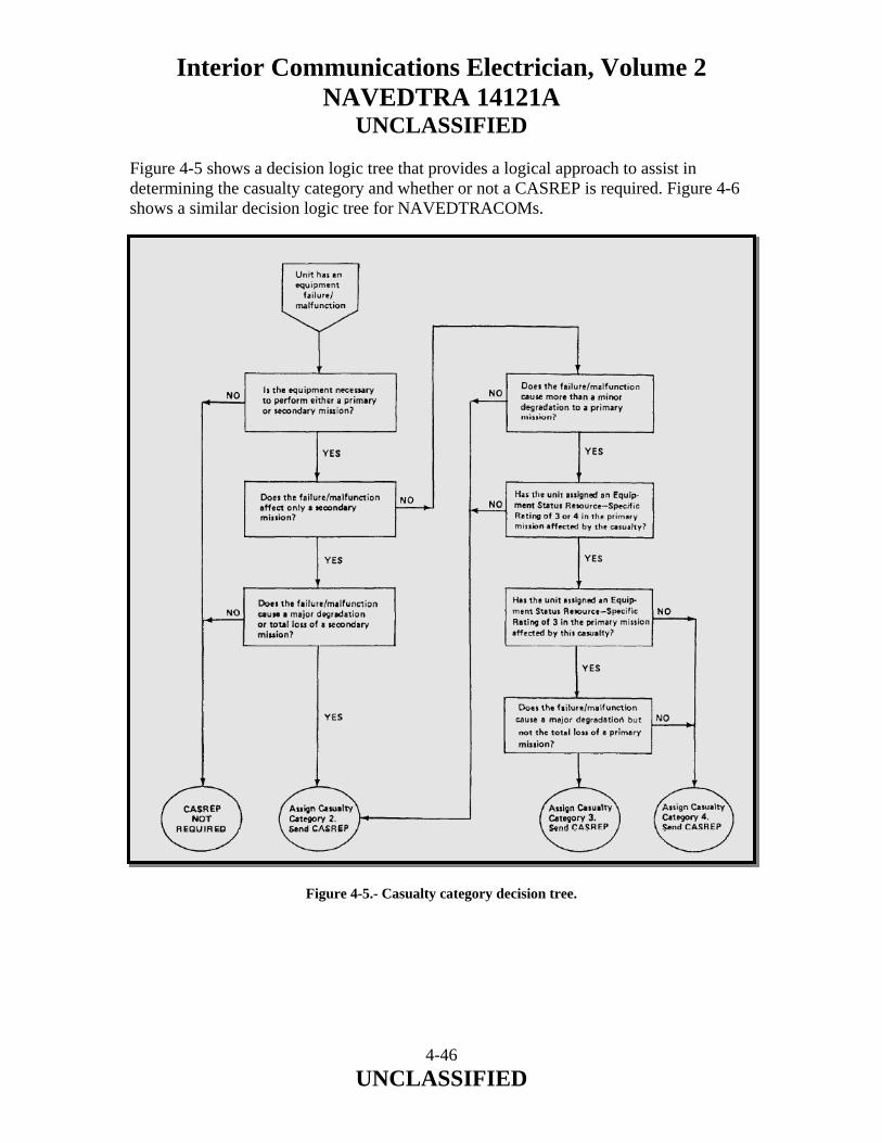
Interior Communications Electrician, Volume 2 NAVEDTRA 14121A
UNCLASSIFIED Figure 4-5 shows a decision logic tree that provides a logical approach to assist in determining the casualty category and whether or not a CASREP is required. Figure 4-6 shows a similar decision logic tree for NAVEDTRACOMs. Figure 4-5.- Casualty category decision tree.
4-46 UNCLASSIFIED
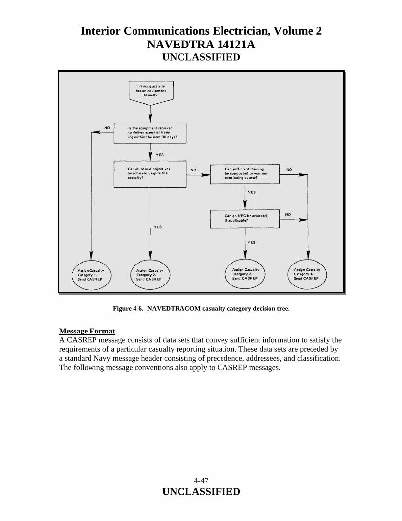
Interior Communications Electrician, Volume 2 NAVEDTRA 14121A
UNCLASSIFIED
Figure 4-6.- NAVEDTRACOM casualty category decision tree. Message Format A CASREP message consists of data sets that convey sufficient information to satisfy the requirements of a particular casualty reporting situation. These data sets are preceded by a standard Navy message header consisting of precedence, addressees, and classification. The following message conventions also apply to CASREP messages.
4-47 UNCLASSIFIED
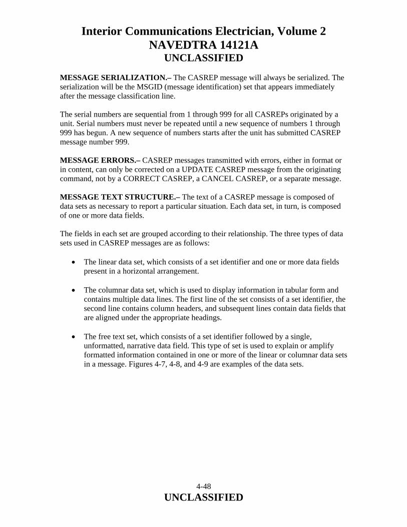
Interior Communications Electrician, Volume 2 NAVEDTRA 14121A
UNCLASSIFIED MESSAGE SERIALIZATION.– The CASREP message will always be serialized. The serialization will be the MSGID (message identification) set that appears immediately after the message classification line. The serial numbers are sequential from 1 through 999 for all CASREPs originated by a unit. Serial numbers must never be repeated until a new sequence of numbers 1 through 999 has begun. A new sequence of numbers starts after the unit has submitted CASREP message number 999. MESSAGE ERRORS.– CASREP messages transmitted with errors, either in format or in content, can only be corrected on a UPDATE CASREP message from the originating command, not by a CORRECT CASREP, a CANCEL CASREP, or a separate message. MESSAGE TEXT STRUCTURE.– The text of a CASREP message is composed of data sets as necessary to report a particular situation. Each data set, in turn, is composed of one or more data fields. The fields in each set are grouped according to their relationship. The three types of data sets used in CASREP messages are as follows:
• The linear data set, which consists of a set identifier and one or more data fields present in a horizontal arrangement.
• The columnar data set, which is used to display information in tabular form and
contains multiple data lines. The first line of the set consists of a set identifier, the second line contains column headers, and subsequent lines contain data fields that are aligned under the appropriate headings.
• The free text set, which consists of a set identifier followed by a single,
unformatted, narrative data field. This type of set is used to explain or amplify formatted information contained in one or more of the linear or columnar data sets in a message. Figures 4-7, 4-8, and 4-9 are examples of the data sets.
4-48 UNCLASSIFIED
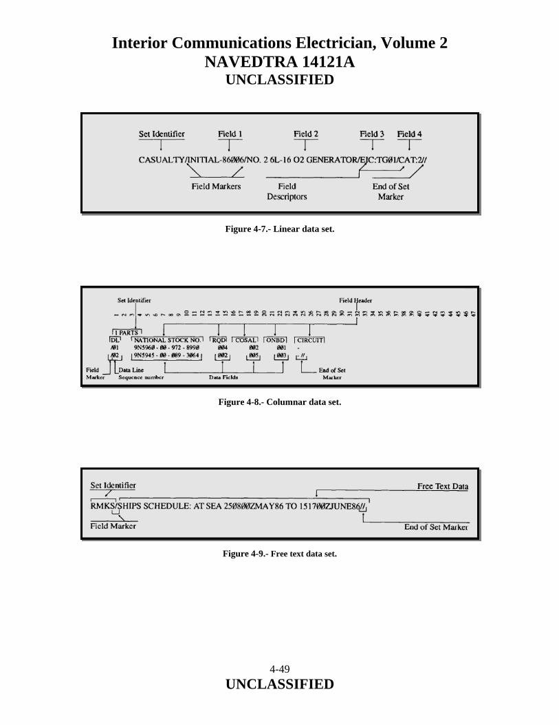
Interior Communications Electrician, Volume 2 NAVEDTRA 14121A
UNCLASSIFIED
Figure 4-7.- Linear data set. Figure 4-8.- Columnar data set. Figure 4-9.- Free text data set.
4-49 UNCLASSIFIED
Interior Communications Electrician, Volume 2 NAVEDTRA 14121A
UNCLASSIFIED Reporting Criteria The following paragraphs will discuss the reporting criteria for each type of CASREP. INITIAL CASREP.— An INITIAL CASREP (fig. 4-10) is used to report the occurrence of a significant equipment casualty and provides specific information concerning repair of the casualty. Only one initial casualty may be submitted per CASREP message. All required information must be submitted in the INITIAL CASREP; best estimates of unavailable data should be provided in the INITIAL CASREP and revised as soon as possible in an UPDATE CASREP. An INITIAL CASREP may also be submitted to request outside assistance; that is, no parts are required to correct an equipment casualty (see fig. 4-11). An INITIAL CASREP must identify, to an appropriate level of detail, the status of the equipment, parts, and assistance requirements. This is essential to allow operational and staff authorities to apply the proper priority to necessary resources. Each INITIAL CASREP must contain a casualty set followed by one or more sets that convey information concerning that casualty. When a casualty results from inadequate general-purpose electronic test equipment (GPETE) or PMS, the affected system must be the subject of the INITIAL CASREP with GPETE or PMS reported as the cause in an amplification (AMPN) set. An assist set must be used to report whether or not a unit requires outside assistance to repair an equipment casualty. When a unit requires assistance and/or parts to repair a casualty, schedule information must be reported in the RMKS set for a full 30-day period, starting on the earliest date that the unit can receive the assistance and/or parts. In addition to the scheduling information, the unit commander may also report any effect the casualty is expected to have on the unit’s employment during the 30-day period.
4-50 UNCLASSIFIED
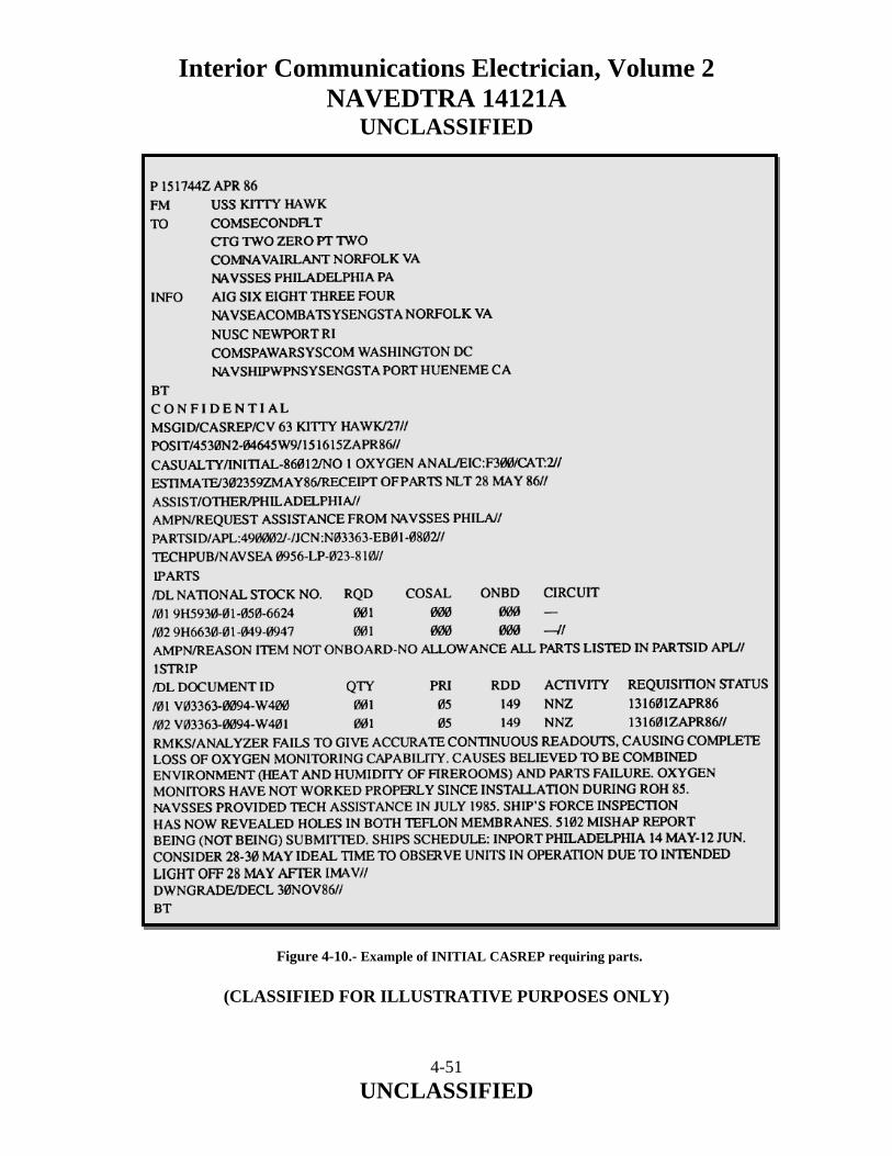
Interior Communications Electrician, Volume 2 NAVEDTRA 14121A
UNCLASSIFIED
Figure 4-10.- Example of INITIAL CASREP requiring parts.
(CLASSIFIED FOR ILLUSTRATIVE PURPOSES ONLY)
4-51 UNCLASSIFIED
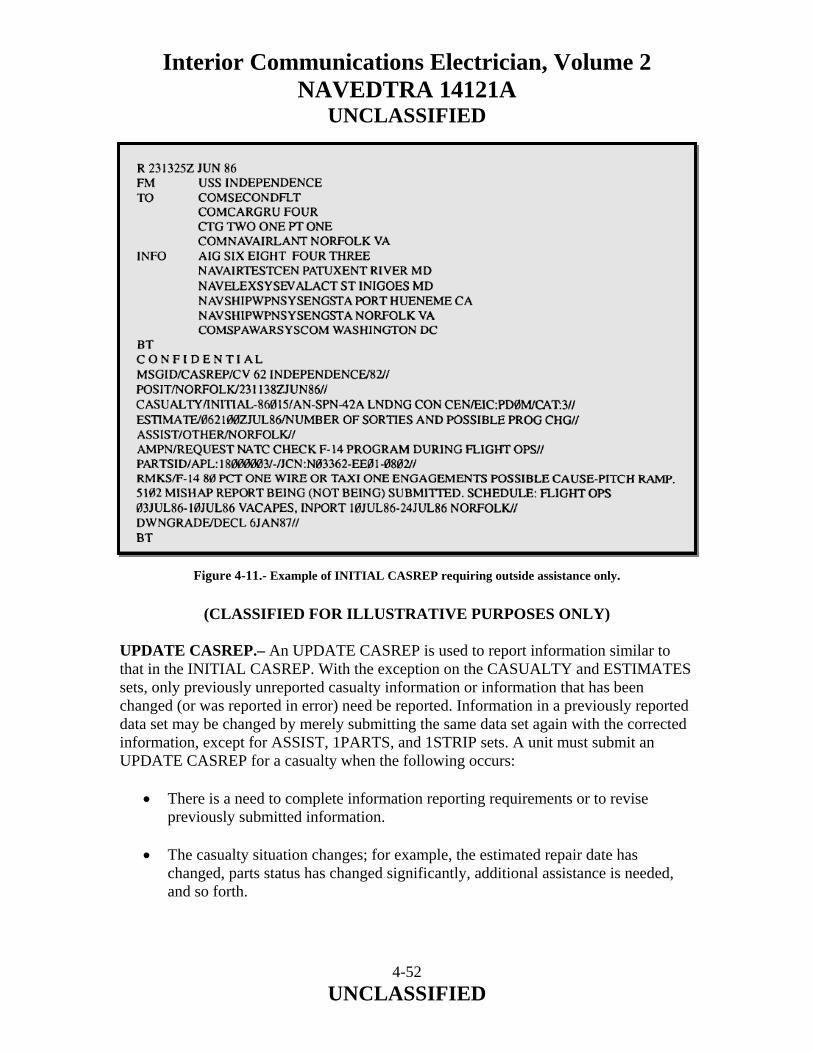
Interior Communications Electrician, Volume 2 NAVEDTRA 14121A
UNCLASSIFIED
Figure 4-11.- Example of INITIAL CASREP requiring outside assistance only.
(CLASSIFIED FOR ILLUSTRATIVE PURPOSES ONLY) UPDATE CASREP.– An UPDATE CASREP is used to report information similar to that in the INITIAL CASREP. With the exception on the CASUALTY and ESTIMATES sets, only previously unreported casualty information or information that has been changed (or was reported in error) need be reported. Information in a previously reported data set may be changed by merely submitting the same data set again with the corrected information, except for ASSIST, 1PARTS, and 1STRIP sets. A unit must submit an UPDATE CASREP for a casualty when the following occurs:
• There is a need to complete information reporting requirements or to revise previously submitted information.
• The casualty situation changes; for example, the estimated repair date has
changed, parts status has changed significantly, additional assistance is needed, and so forth.
4-52 UNCLASSIFIED
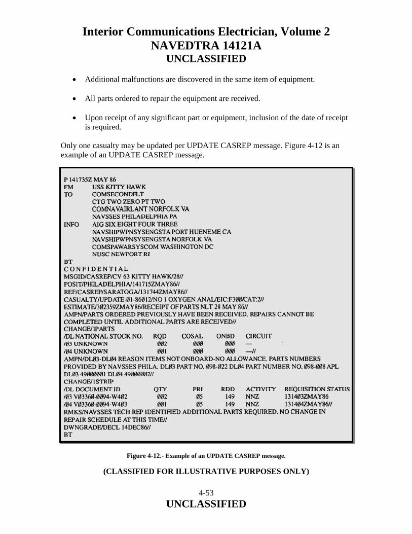
Interior Communications Electrician, Volume 2 NAVEDTRA 14121A
UNCLASSIFIED
• Additional malfunctions are discovered in the same item of equipment.
• All parts ordered to repair the equipment are received.
• Upon receipt of any significant part or equipment, inclusion of the date of receipt is required.
Only one casualty may be updated per UPDATE CASREP message. Figure 4-12 is an example of an UPDATE CASREP message. Figure 4-12.- Example of an UPDATE CASREP message.
(CLASSIFIED FOR ILLUSTRATIVE PURPOSES ONLY)
4-53 UNCLASSIFIED
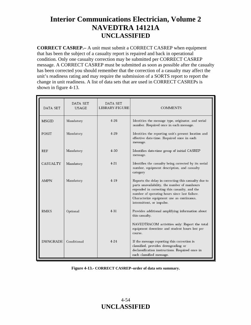
Interior Communications Electrician, Volume 2 NAVEDTRA 14121A
UNCLASSIFIED CORRECT CASREP.– A unit must submit a CORRECT CASREP when equipment that has been the subject of a casualty report is repaired and back in operational condition. Only one casualty correction may be submitted per CORRECT CASREP message. A CORRECT CASREP must be submitted as soon as possible after the casualty has been corrected you should remember that the correction of a casualty may affect the unit’s readiness rating and may require the submission of a SORTS report to report the change in unit readiness. A list of data sets that are used in CORRECT CASREPs is shown in figure 4-13.
Figure 4-13.- CORRECT CASREP–order of data sets summary.
4-54 UNCLASSIFIED
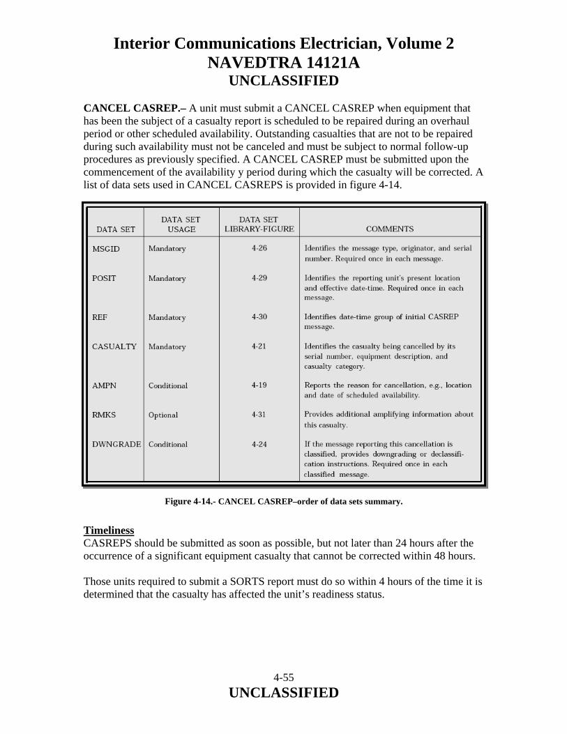
Interior Communications Electrician, Volume 2 NAVEDTRA 14121A
UNCLASSIFIED CANCEL CASREP.– A unit must submit a CANCEL CASREP when equipment that has been the subject of a casualty report is scheduled to be repaired during an overhaul period or other scheduled availability. Outstanding casualties that are not to be repaired during such availability must not be canceled and must be subject to normal follow-up procedures as previously specified. A CANCEL CASREP must be submitted upon the commencement of the availability y period during which the casualty will be corrected. A list of data sets used in CANCEL CASREPS is provided in figure 4-14.
Figure 4-14.- CANCEL CASREP–order of data sets summary. Timeliness CASREPS should be submitted as soon as possible, but not later than 24 hours after the occurrence of a significant equipment casualty that cannot be corrected within 48 hours. Those units required to submit a SORTS report must do so within 4 hours of the time it is determined that the casualty has affected the unit’s readiness status.
4-55 UNCLASSIFIED

Interior Communications Electrician, Volume 2 NAVEDTRA 14121A
UNCLASSIFIED Precedence CASREP messages must be assigned the lowest precedence consistent with the importance of the type of report, the unit’s current operational schedule, the location, and the tactical situation. Deployed units must assign a precedence of at least priority 4 to CASREP messages. Addressal Procedures As you can see by the example CASREP messages, the examples listed are commands, activities, and the like that are concerned with your unit’s casualty. They may be a command or activity that will expedite the assistance as applicable. These addresses will vary with major geographical locations, such as the Pacific, Atlantic, Caribbean, and Mediterranean. The senior operational commander, immediate operational commander, and cognizant type commander, or designated deputy, must be action addressees on all CASREP messages. All other addressees can be found in NWP 1-03.1. When writing CASREPs (INITIAL, UPDATE, CANCEL, and CORRECT), you should constantly refer to NWP 1-03.1 for proper format and terminology, as this chapter was written to give you a brief overview and not for you to use as an in-depth guide. Situation Reports Situation reports (SITREPs) are one-time reports required when certain situations arise. Figure 4-15 is a summary of one-time reports pertaining to the engineering department. The situation that occasions the reports listed in the summary are explained in the references listed.
4-56 UNCLASSIFIED
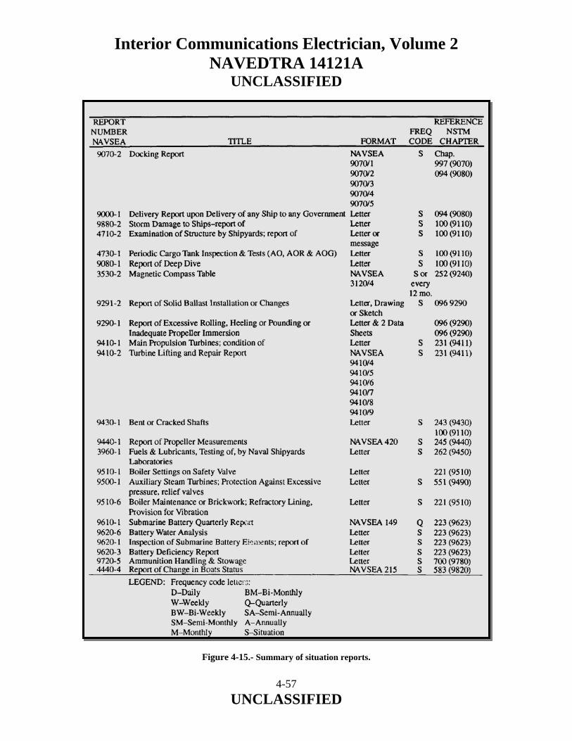
Interior Communications Electrician, Volume 2 NAVEDTRA 14121A
UNCLASSIFIED Figure 4-15.- Summary of situation reports.
4-57 UNCLASSIFIED

Interior Communications Electrician, Volume 2 NAVEDTRA 14121A
UNCLASSIFIED
4-58 UNCLASSIFIED
4.13.0 SUMMARY In this chapter, we have described the system used for equipment calibration. We have identified and discussed the Metrology Automated System for Uniform Recall and Reporting (MEASURE) program. We have described the different calibration statuses of equipment and described the procedures in updating equipment calibration schedules. We have discussed the steps in preparing and reviewing casualty reports (CASREPs), casualty corrections (CASCORs), and situation reports (SITREPs).

Interior Communications Electrician, Volume 2 NAVEDTRA 14121A
UNCLASSIFIED
5 QUALITY ASSURANCE Upon completion of this chapter, you should be able to do the following:
• Describe the purpose and goal of the Quality Assurance (QA) program. • Identify the chain of command for a QA program and the responsibilities of
personnel in the chain of command. • Describe QA personnel qualification requirements. • Describe the operation of a QA program. • Identify the definitions of terms used in QA. • Describe the levels of essentiality. • Identify the purpose of tests and inspections associated with the QA program. • Describe the responsibilities of personnel conducting tests and inspections. • Discuss the requirements and procedures in conducting a QA program inspection. • Recognize the contents and format of various QA forms and reports. • Identify the steps in preparing various QA forms and reports. • Recognize the contents and format of other forms that are to be submitted in
conjunction with QA forms and reports.
5-1 UNCLASSIFIED

Interior Communications Electrician, Volume 2 NAVEDTRA 14121A
UNCLASSIFIED 5.0.0 INTRODUCTION As you progress towards IC1 or ICC, your responsibilities become more involved in quality assurance (QA). You will be responsible for ensuring that the work performed by your technicians and by outside help is completed with the highest quality possible. Most of the personnel in the IC rating take pride in the performance of their jobs and they normally strive for excellence. As the work group or work center supervisor, one of your many responsibilities will be to ensure that all corrective action performed is done correctly and meets prescribed standards. Improper performance of repairs or installations could endanger the lives of personnel or an expensive piece of equipment or cause another piece of equipment to fail prematurely. A well-organized QA and inspection program will minimize the impact of a moment of carelessness or inattention. This chapter will familiarize you with the purpose, basic organization, and mechanics of the QA program. You may be assigned as a QA representative or collateral duty inspector from time to time. As a work center supervisor, you will be responsible for the quality control (QC) program in your workspaces. It is important that you become quality conscious. To make any program successful, you will have to know and understand the QA program and obtain the cooperation and participation of all your personnel. This requires you to ensure that all tests and repairs conform to their prescribed standards. In addition, you as a supervisor must train all your personnel in QC. 5.1.0 QUALITY ASSURANCE PROGRAM The QA program was established to provide personnel with information and guidance necessary to administer a uniform policy of maintenance and repair of ships and submarines. The QA program is intended to impart discipline into the repair of equipment, safety of personnel, and configuration control, thereby enhancing ship’s readiness. The various QA manuals set forth minimum QA requirements for both the surface fleet and the submarine force. If more stringent requirements are imposed by higher authority, such requirements take precedence. If conflicts exist between the QA manual and previously issued letters and transmittals by the appropriate force commanders, the QA manual takes precedence. Such conflicts should be reported to the appropriate officials.
5-2 UNCLASSIFIED

Interior Communications Electrician, Volume 2 NAVEDTRA 14121A
UNCLASSIFIED The instructions contained in the QA manual apply to every ship and activity of the force. Although the requirements are primarily applicable to the repair and maintenance done by the force intermediate maintenance activities (IMAs), they also apply to maintenance done aboard ship by ship’s force. In all cases, when specifications cannot be met, a departure from specifications request must be completed and reported. Because of the wide range of ship types and equipment and the varied resources available for maintenance and repair, the instructions set forth in the QA manual are general in nature. Each activity must implement a QA program to meet the intent of the QA manual. The goal should be to have all repairs conform to QA specifications. 5.1.1 Program Components The basic thrust of the QA program is to ensure that you comply with technical specifications during all work on ships of both the surface fleet and the submarine force. The key elements of the program are as follows:
• Administrative. This includes training and qualifying personnel, monitoring and auditing programs, and completing the QA forms and records.
• Job Execution. This includes preparing work procedures, meeting controlled
material requirements, requisitioning material, conducting in-process control of fabrication and repairs, testing and recertifying, and documenting any departure from specifications.
5.1.2 Concepts of Quality Assurance The ever-increasing technical complexity of present-day surface ships and submarines has spawned the need for special administrative and technical procedures known collectively as the QA program. The QA concept is fundamentally the prevention of defects. This encompasses all events from the start of maintenance operations until their completion. It is the responsibility of all maintenance personnel. Achievement of QA depends on prevention of maintenance problems through your knowledge and special skills. As a supervisor, you must consider QA requirements whenever you plan maintenance. The fundamental rule for you to follow for all maintenance is that TECHNICAL SPECIFICATIONS MUST BE MET AT ALL TIMES. Prevention is concerned with regulating events rather than being regulated by them. It relies on eliminating maintenance failures before they happen. This extends to safety of personnel, maintenance of equipment, and virtually every aspect of the total maintenance effort.
5-3 UNCLASSIFIED

Interior Communications Electrician, Volume 2 NAVEDTRA 14121A
UNCLASSIFIED Knowledge is obtained from factual information. This knowledge is acquired through the proper use of data collection and analysis programs. The maintenance data collection system provides maintenance managers unlimited quantities of factual information. The experienced maintenance manager provides management with a pool of knowledge. Correct use of this knowledge provides the chain of command with the tools necessary to achieve maximum shipboard readiness. Special skills, normally not possessed by production personnel, are provided by a staff of trained personnel for analyzing data and supervising QA programs. The QA program provides an efficient method for gathering and maintaining information on the quality characteristics of products and on the source and nature of defects and their impact on current operations. It permits decisions to be based on facts rather than intuition or memory. It provides comparative data that will be useful long after details of particular times or events have been forgotten. QA requires both authority and assumption of responsibility for action. A properly functioning QA program points out problem areas to maintenance managers so they can take appropriate action to accomplish the following:
• Improve the quality, uniformity, and reliability of the total maintenance effort. • Improve the work environment, tools, and equipment used in the performance of
maintenance. • Eliminate unnecessary man-hour and dollar expenses. • Improve the training, work habits, and procedures of maintenance personnel. • Increase the excellence and value of reports and correspondence originated by the
maintenance activity. • Distribute required technical information more effectively. • Establish realistic material and equipment requirements in support of the
maintenance effort. To obtain full benefits from a QA program, teamwork must be achieved first. Blend QA functions in with the interest of the total organization and you produce a more effective program. Allow each worker and supervisor to use an optimum degree of judgment in the course of the assigned daily work; a person’s judgment plays an important part in the quality of the work. QA techniques supply each person with the information on actual quality. This information provides a challenge to the person to improve the quality of the work. The resulting knowledge encourages the best efforts of all your maintenance personnel.
5-4 UNCLASSIFIED

Interior Communications Electrician, Volume 2 NAVEDTRA 14121A
UNCLASSIFIED QA is designed to serve both management and production equally. Management is served when QA monitors the complete maintenance effort of the department, furnishes factual feedback of discrepancies and deficiencies, and provides the action necessary to improve the quality, reliability, and safety of maintenance. Production is served by having the benefit of collateral duty inspectors formally trained in inspection procedures; it is also served in receiving technical assistance in resolving production problems. Production personnel are not relieved of their basic responsibility for quality work when you introduce QA to the maintenance function. Instead, you increase their responsibility by adding accountability. This accountability is the essence of QA. 5.1.3 Goals The goals of the QA program are to protect personnel from hazardous conditions, increase the time between equipment failure, and ensure proper repair of failed equipment. The goals of the QA program are intended to improve equipment reliability, safety of personnel, and configuration control. Achievement of these goals will ultimately enhance the readiness of ship and shore installations. There is a wide range of ship types and classes in the fleet, and there are equipment differences within ship classes. This complicates maintenance support and increases the need for a formalized program that will provide a high degree of confidence that overhaul, installations, repairs, and material will consistently meet conformance standards. 5.1.4 The Quality Assurance Link to Maintenance Accomplishment of repairs and alterations according to technical specifications has been a long-standing requirement for U.S. Navy ships. Ultimate responsibility to ensure that this requirement is met rests with the person performing the maintenance. To do the job properly, a worker must be:
• properly trained, • provided with correct tools and parts, • familiar with the applicable technical manuals and plans, and, • adequately supervised.
These elements continue to be the primary means of assuring that maintenance is performed correctly. As a supervisor, you can readily see where you fit in.
5-5 UNCLASSIFIED

Interior Communications Electrician, Volume 2 NAVEDTRA 14121A
UNCLASSIFIED Once the need for maintenance is identified, you must consider QA requirements concurrently with the planning and performing of that maintenance. Technical specifications will come from a variety of sources. The determination of which sources are applicable to the particular job will be the most difficult part of your planning effort. Once you make that determination, the maintenance objective becomes two-fold: 1. Ensure the maintenance effort meets all specifications. 2. Ensure the documentation is complete, accurate, and auditable. It is vital that you approach maintenance planning from the standpoint of first-time quality. 5.2.0 THE QUALITY ASSURANCE ORGANIZATION The QA program for naval forces is organized into different levels of responsibility. For example, the QA program for the Naval Surface Force for the Pacific Fleet is organized into the following levels of responsibility: type commander, readiness support group/area maintenance coordinator, and the IMAs. The QA program for the submarine force is organized into four levels of responsibility: type commander, group and squadron commanders, IMA commanding officers, and ship commanding officer/officers in charge. The QA program for the Naval Surface Force for the Atlantic Fleet is organized into five levels of responsibility: force commander, audits, squadron commanders, IMAs, and force ships. The QA program organization (Navy) begins with the commanders in chief of the fleets, which provides the basic QA program organization responsibilities and guidelines. The type commanders (TYCOMs) provide instruction, policy, and overall direction for implementation and operation of the force QA program. TYCOMs have a force QA officer assigned to administer the force QA program. The commanding officers (COs) are responsible to the force commander for QA in the maintenance and repair of the ships. The CO is responsible for organizing and implementing a QA program within the ship to carry out the provisions of the TYCOMs QA manual. The CO ensures that all repair actions performed by ship’s force conform to provisions of the QA manual as well as pertinent technical requirements.
5-6 UNCLASSIFIED

Interior Communications Electrician, Volume 2 NAVEDTRA 14121A
UNCLASSIFIED The CO ensures that all work requests requiring special controls are properly identified and that applicable supporting documentation is provided to the maintenance or repair activity using the applicable QA form. The CO also ensures that departures from specifications are reported, required audits are conducted, and adequate maintenance is performed for the material condition necessary to support continued unrestricted operations. The quality assurance officer (QAO) is responsible to the CO for the organization, administration, and execution of the ship’s QA program according to the QA manual. On most surface ships other than IMAs, the QAO is the chief engineer, with a senior chief petty officer assigned as the QA coordinate. The QAO is responsible for the following:
• Coordinating the ship’s QA training program Maintaining ship’s QA records and inspection reports according to the QA manual
• Maintaining auditable departure from specification records • Reviewing procedures and controlled work packages prepared by the ship before
submission to the engineer • Conducting QA audits as required by the QA manual and following upon
corrective actions to ensure compliance with the QA program • Maintaining liaison with the IMA office for all work requiring QA controls • Providing QA guidance to the supply department when required • Preparing QA/QC reports (as required) by higher authority • Maintaining liaison with the ship engineer in all matters pertaining to QA to
ensure compliance with the QA manual The ship quality control inspectors (SQCIs), usually the work center supervisor and two others from the work center, must have a thorough understanding of the QA program. Some of the other responsibilities an SQCI will have are as follows:
• Maintain ship records to support the QA program. • Inspect all work for conformance to specifications. • Ensure that only calibrated equipment is used in acceptance testing and inspection
of work. • Witness and document all tests. • Ensure that all materials or test results that fail to meet specifications are recorded
and reported. • Train personnel in QC.
5-7 UNCLASSIFIED

Interior Communications Electrician, Volume 2 NAVEDTRA 14121A
UNCLASSIFIED
• Initiate departure from specification reports (discussed later) when required. • Ensure that all inspections beyond the capabilities of the ship’s QA inspector are
performed and accepted by IMA before final acceptance and installation of the product by the ship.
• Report all deficiencies and discrepancies to the ship’s QA coordinator (keeping the division officer informed).
• Develop controlled work packages for all ship repair work requiring QA controls. More on SQCI duties will be discussed later in this chapter, because this will more than likely be the area you will be associated with. 5.3.0 RESPONSIBILITIES FOR QUALITY OF MAINTENANCE Although the CO is responsible for the inspection and quality of material within a command, he or she depends on the full cooperation of all hands to meet this responsibility. The responsibility for establishing a successful program to attain high standards of quality workmanship cannot be discharged by merely creating a QA division within a maintenance organization. To operate effectively, this division requires the full support of everyone within the organization. It is not the instruments, instructions, and other facilities for making inspections that determine the success or failure in achieving high standards of quality; it is the frame of mind of all personnel. Quality maintenance is vital to the effective operation of any maintenance organization. To achieve this high quality of world each of your personnel must know not only a set of specification limits, but also the purpose for these limits. The person with the most direct concern for quality workmanship is you–the production supervisor. This stems from your responsibility for the professional performance of your assigned personnel. You must establish procedures within the work center to ensure that all QA inspection requirements are complied with during all maintenance evolutions. In developing procedures for your work center, keep in mind that inspections normally fall into one of the three following inspection areas:
• RECEIVING OR SCREENING INSPECTIONS. These inspections apply to material, components, parts, equipment, logs, records, and documents. These inspections determine the condition of material, proper identification, maintenance requirements, disposition, and correctness of accompanying records and documents.
5-8 UNCLASSIFIED

Interior Communications Electrician, Volume 2 NAVEDTRA 14121A
UNCLASSIFIED
• IN-PROCESSING INSPECTIONS. These inspections are specific QA actions that are required during maintenance or actions in cases where satisfactory task performance cannot be determined after maintenance has been completed. These inspections include witnessing, application of torque, functional testing, adjusting, assembling, servicing, and installation.
• FINAL INSPECTION. These inspections comprise specific QA actions
performed following the completion of a task or series of tasks. QA inspection of work areas following task completion by several different personnel is an example of a final inspection.
You have the direct responsibility as production supervisor to assign a collateral duty inspector at the time you assign work. This allows your inspector to make the progressive inspection(s) required; the inspector is not then confronted with a job already completed, functionally tested, and buttoned up. Remember, production personnel to which you have assigned the dual role of inspector cannot inspect or certify their own work. 5.3.1 Ship Quality Control Inspector The SQCI is the frontline guardian of adherence to quality standards. In the shops and on the deck plates, the SQCIs must constantly remind themselves that they can make a difference in the quality of a product. They must be able to see and be recognized for their contributions in obtaining quality results. As a work center supervisor, you will be responsible for the QA program in your work spaces. You must realize that QA inspections are essential elements of an effective QA program. You are responsible to your division officer and the QAO for coordinating and administering the QA program within your work center. You are responsible for ensuring that all repaired units are ready for issue. This doesn’t mean you have to inspect each item repaired in your shop personally; you should have two reliable, well-trained technicians to assist you in QA inspections. To avoid the many problems caused by poor maintenance repair practices or by the replacement of material with faulty or incorrect material, you must take your position as an SQCI very seriously. When you inspect a certain step of installation, ensure to the utmost of your knowledge and ability that the performance and product meet specifications and that installations are correct.
5-9 UNCLASSIFIED

Interior Communications Electrician, Volume 2 NAVEDTRA 14121A
UNCLASSIFIED Most commands that have a QA program will issue you a special card that will identify you as a qualified SQCI for your command. Each of your shop SQCIs also will be assigned a personal serial number by the QAO as proof of certification to use on all forms and tags that require initials as proof that certified tests and inspections were completed. This will provide documented proof and traceability that each item or lot of items meets the material and workmanship for that stage of workmanship. Also, you will be given a QCI stamp so that you can stamp the QCI certification on the forms or tags as checkoff of a particular progressive step of inspection or final job completion. The stamp will also serve as proof of inspection and acceptance of each satisfactory shop end product. This stamp may have your command identification and a QCI number that is assigned and traceable to you. As an SQCI, you should be thoroughly familiar with all aspects of the QA program and the QC procedures and requirements of your specialty. You will be trained and qualified by the QAO according to the requirements set forth by your applicable QA manual and the QC requirements applicable to your installation. The QAO will interview you to determine your general knowledge of records, report completion, and filing requirements. You will report to the appropriate QA supervisors while keeping your division officer informed of matters pertaining to QA work done in the shop. You and your work center QCIs will be responsible for the following:
• Developing a thorough understanding of the QA program. • Ensuring that all shop work performed by your work center personnel meets the
minimum requirements set forth in the latest plans, directives, and specifications of higher authority and that controlled work packages (CWPs) are properly used on repair work.
• Ensuring that all work center personnel are familiar with applicable QA manuals by conducting work center/division training.
• Maintaining records and files to support the QA program, following the QA manual.
• Assuring that your work center and, when applicable, division personnel do not use measuring devices, instruments, inspection tools, gauges, or fixtures for production acceptance and testing that do not have current calibration stickers or records attached or available.
5-10 UNCLASSIFIED

Interior Communications Electrician, Volume 2 NAVEDTRA 14121A
UNCLASSIFIED
• Performing quality control inspections of each product manufactured or repaired by your work center.
• Assisting your division officer and QAO in conducting internal audits as required and taking corrective action on noted discrepancies.
Alternate SQCIs are usually assigned as backups to the regular SQCIs. Their qualifications and responsibilities will be the same as those of the regularly assigned SQCI. 5.3.2 Work Center Controlled Material Petty Officers As a supervisor, you must also ensure that procedures governing controlled material are followed. You can do this by having one or more of your work center personnel trained in the procedures for inspecting, segregating, stowing, and issuing controlled material. When they have completed their training, designate them as controlled material petty officers (CMPOs). 5.3.4 Shop Craftsman As stated earlier, the person doing the work, whether it be manufacturing or repairing, is responsible to you when questions arise about the work being performed, whether the work is incorrect, incomplete, or unclear. Make sure your workers know to stop and seek work instructions or clarification from you when questions or conditions arise which may present an impediment to the successful completion of the task at hand. A good lesson to teach over and over to all workers is to strive to achieve first-time quality on every task assigned. This not only will instill pride and professionalism in their work, but also will ensure a quality product. 5.4.0 QULAITY ASSURANCE REQUIREMENTS TRAINING, AND QUALIFICATION A comprehensive personnel training program is the next step in an effective QA program. For inspectors to make a difference, they must be both trained and certified. They must have formal or informal training in inspection methods, maintenance and repair, and certification of QA requirements. Costly mistakes, made either from a lack of knowledge or improper training, can be entirely eliminated with a good QA training program at all levels of shop or work group organization.
5-11 UNCLASSIFIED

Interior Communications Electrician, Volume 2 NAVEDTRA 14121A
UNCLASSIFIED Before personnel can assume the responsibility of coordinating, administering, and executing the QA program, they must meet certain requirements. Personnel assigned to the QA division or QC personnel you have assigned in your work center, such as SQCIs, CMPOs, or their alternates, should be highly motivated towards the QA program. It is imperative that a qualification and requalification program be established for those personnel participating in the program. Where military standards and NAVSEA technical documents require formal technical training or equivalent, those requirements must be met and personnel qualification vigorously and effectively monitored to ensure that qualifications are updated and maintained. When formal training for a specific skill is not a requirement, the guidelines of the QA manual may be used as a basis for training to ensure that personnel are provided with the necessary expertise to perform a required skill. Personnel who obtain a QA qualification must undergo periodic QA training and examinations, both oral and written, to maintain the qualification. We will discuss this procedure in the following paragraphs. 5.4.1 Quality Assurance Officer The QAO’s primary duty, assigned by the CO in writing, is to oversee the QA program. The QAO ensures that personnel assigned to perform QA functions receive continuous training in inspecting, testing, and QC methods specifically applicable to their area of assignment. The QAO also ensures that SQCIs receive cross training to perform QA functions not in their assigned area. This training includes local training courses, on-the-job training (OJT), rotation of assignments, personnel qualification standards (PQS), and formal schools. Whenever possible, the QAO receives formal training according to the QA manual. He or she is responsible to the repair officer for planning and executing a QA training program for the various qualifications required for QA. The QAO personally interviews each perspective SQCI to ensure that the person has a thorough understanding of the QA mission. 5.4.2 Repair Officer The repair officer (RO) maintains qualified personnel in all required ratings for the QA program in his or her department. He or she also ensures that personnel assigned to the repair department are indoctrinated and trained in QA practices and requirements.
5-12 UNCLASSIFIED

Interior Communications Electrician, Volume 2 NAVEDTRA 14121A
UNCLASSIFIED 5.4.3 Division Officers Division officers ensure that their divisional personnel receive training and are qualified in the QA process and maintain those qualifications. They make sure that all repairs, inspections, and production work requiring a witness are witnessed by division work center QC inspectors and that all test records arc completed and signed. Division officers ensure that all test personnel observe all safety precautions pertaining to the specific equipment and wear personal safety equipment at all times while conducting these evolutions. They also make sure that test equipment, if required, is properly calibrated and that adequate overpressure protection is provided during division spaces. 5.4.4 Quality Assurance Supervisors QA supervisors are senior petty officers who have been properly qualified according to the QA manual. They have a thorough understanding of the QA function and are indoctrinated in all aspects of the coordinating, administering, and auditing processes of the QA program. QA supervisors train all SQCIs and CMPOs and ensure their recertification upon expiration of qualifications. QA supervisors also administer written examinations to all perspective SQCIs and those SQCIs who require recertification to ensure a thorough understanding of the QA program. 5.4.5 Ship Quality Control Inspectors SQCIs are trained by the QA supervisors in applicable matters pertaining to the QA program. An inspector must be equally as skilled as the craftsman whose work he or she is required to inspect. Not only should the inspector know the fabrication or repair operation and what workers are required to do, but also how to go about doing it. To recognize a product quality characteristic, SQCIs must be given certain tools and training. Tools of their trade should include measuring devices and documentation. Their training is both formal (documented course of instruction) and informal (OJT). They must pass a written test given by the QA supervisor, as well as an oral examination given by the QAO. The written exam includes general requirements of the QA program and specific requirements relative to their particular specialty. Successful completion of the shop qualification program course for QCIs will fulfill this requirement. The QA supervisor may also administer a practical examination to perspective SQCIs in which they will have to demonstrate knowledge of records and report completion, and tiling requirements. This will ensure that the SQCIs have a general knowledge of and proper attitude toward the QA program.
5-13 UNCLASSIFIED

Interior Communications Electrician, Volume 2 NAVEDTRA 14121A
UNCLASSIFIED 5.4.6 Controlled Material Petty Officers CMPOs are normally petty officers, E-4 or E-5, who are thoroughly familiar with controlled material requirements as outlined in the QA manual. They, too, are trained and qualified by a QA supervisor. The QAO will interview them, as he or she did for the SQCIs, to see if they have a general knowledge of controlled material requirements. The QA supervisor will give them a written test to ensure that they have sufficient knowledge of controlled material requirements and procedures to carry out their responsibilities effectively. 5.5.0 OPERATION OR A QUALITY ASSURANCE PROGRAM Initiating an effective, ongoing QA program is an all-hands effort. It takes the cooperation of all shop personnel to make the program work. As the shop or work group supervisor, you will be responsible for getting the program rolling. The key elements are a good personnel orientation program, a comprehensive personnel training program, use of the proper repair procedures, and uniform inspection procedures. When you have organized the shop or work center and have placed all these elements in practice, your QA program will be underway. These elements are discussed in the following paragraphs. 5.5.1 Personnel Orientation The best way to get the support of your personnel is to show them how an effective QA program will benefit them personally. Eliminating or reducing premature failures in repaired units and introducing high-reliability repairs will appreciable y reduce their workload, saving them frustration and enhancing the shop or work group reputation. This program, as any new program or change to an existing program, will probably meet with opposition from some shop personnel. By showing your shop personnel the benefits of a QA program, you greatly reduce opposition to the change. 5.5.2 Repair Procedures Repair procedures may be defined as all of the action required to return equipment to its proper operating condition after a defect has been discovered. Repair procedures include parts handling, disassembly, component removal or replacement, and reassembly. Strictly adhering to the proper repair procedures will almost entirely eliminate premature failures. You, as shop supervisor or work group supervisor, and subordinate work center supervisors are responsible for ensuring that the proper procedures are used in handling all repairable units.
5-14 UNCLASSIFIED

Interior Communications Electrician, Volume 2 NAVEDTRA 14121A
UNCLASSIFIED 5.6.0 QUALITY ASSURANCE TERMS AND DEFINITIONS As a supervisor, you need to be able to talk to your personnel about QA and have them be able to carry out your instructions properly and promptly. You need to promote the use of words and phrases pertaining to quality and related programs, thus improving the clarity in your communication with them about QA. To do this, you need to understand the terms frequently used throughout the QA program. Each TYCOM’s QA manual and MIL-STD-109 has a complete list of these terms, but the most frequently used terms are listed here: QUALITY ASSURANCE. Quality assurance (QA) is a system that ensures that materials, data, supplies, and services conform to technical requirements and that repaired equipment performs satisfactory. QUALITY CONTROL. Quality control (QC) is a management function that attempts to eliminate defective products, whether they are produced or procured. ACCEPTANCE. Acceptance is when an authorized representative approves specific services rendered (such as a repair or manufactured part). CALIBRATION. This is the comparison of two instruments or measuring devices, one of which is a standard of known accuracy traceable to national standards, to detect, correlate, report, or eliminate by adjustment any discrepancy in accuracy of the instrument or measuring device being compared with the standard. INSPECTION. This is the examination and testing of components and services to determine whether they conform to specified requirements. IN-PROCESS INSPECTION. This type of inspection is performed during the manufacture and repair cycle to prevent production defects. It is also performed to identify production problems or material defects that are not detectable when the job is complete. INSPECTION RECORD. Inspection records contain data resulting from inspection actions. SPECIFICATIONS. A specification is any technical or administrative directive, such as an instruction, a technical manual, a drawing, a plan, or publication that defines repair criteria.
5-15 UNCLASSIFIED

Interior Communications Electrician, Volume 2 NAVEDTRA 14121A
UNCLASSIFIED AUDIT. An audit, as it applies to the QA program, is a periodic or special evaluation of details, plans, policies, procedures, products, directives, and records necessary to determine compliance with existing requirements. CERTIFIED (LEVEL 1) MATERIAL. This is material that has been certified (as to its material and physical properties as well as traceability to the manufacturer) by a qualified certification activity. This material has a material and identification control (MIC) number assigned along with a certification document. CONTROLLED MATERIAL. This is any material that must be accounted for and identified throughout the manufacturing or repair process. (See level of essentiality.) CONTROLLED WORK PACKAGE. A controlled work package (CWP) is an assemblage of documents identified by a unique serial number that may contain detailed work procedures, purchase documents, receipt inspection reports, objective quality evidence, local test results, and any tags, papers, prints, plans, and soon that bear on the work performed. This will be discussed later in the chapter. DEPARTURE FROM SPECIFICATION. This is a lack of compliance with any authoritative document, plan, procedure, or instruction. A detailed discussion will follow later in the chapter. DOCUMENTATION. This is the record of objective evidence establishing the requisite quality of the material, component, or work done. LEVEL OF ESSENTIALITY. A level of essentiality is a certain level of confidence required in the reliability of repairs made. The different levels of essentiality will be discussed later in the chapter. PROCEDURE. A procedure is a written instruction designed for use in production and repair, delineating all essential elements and guidance necessary to produce acceptable and reliable products. PROCESS. This is a set of actions written in a special sequential order by which a repair or maintenance action, a test, or an inspection is done using specific guidelines, tools, and equipment. RELIABILITY. Reliability means the probability that an item will perform its intended function for a specified interval under stated conditions.
5-16 UNCLASSIFIED

Interior Communications Electrician, Volume 2 NAVEDTRA 14121A
UNCLASSIFIED SUBSAFE. The acronym SUBSAFE is a short reference to the Submarine Safety Program, which provides a high level of confidence in the material conditions of the hull integrity boundary. SUBSAFE will be discussed later in this chapter. 5.7.0 THE CONTROLLED WORK PACKAGE To provide additional assurance that a quality product will result from the in-process fabrication or repair, the CWP was developed. It provides QC techniques (requirements or procedures) and shows objective quality evidence (documentation) of adherence to specified quality standards. These requirements or procedures include both external (TYCOM) and internal (command-generated) information for work package processing and sign-off. The typical CWP that will arrive at your desk will have QA forms, departure from specifications forms, material deficiency forms, production task control forms, and QC personnel sign-off requirements. You, and all the other work centers involved in the performance of the task, must review the contents of each package as well. When you review the package, check that the requirements specified for their accomplishment are correct, in a correct sequence, and so on. Each CWP covers the entire scope of the work process and is able to stand on its own. Traceability from the work package to other certification documentation is provided by the job control number (JCN). You must ensure that the CWP is at the job site during the performance of the task. If the work procedure requires the simultaneous performance of procedure steps and these steps are done in different locations, use the locally developed practices to ensure you maintain positive control for each step. Immediately after a job is completed, but before the ship gets underway, each assigned work center and the QAO will review the work package documentation for completeness and correctness. If you and your workers have been doing the assigned steps as stated, this should not be a problem. Ensure that all the verification signature blocks are signed. Make sure all references, such as technical manuals or drawings, are returned to the appropriate place. 5.7.1 Enclosures You will find a lot of documentation inside the CWP when it arrives at your desk. Inside will be process instructions, plans, technical drawings, and instructions pertinent to the production job at hand. Documents listed as references are not intended to be included in the CWP, but they must be available when required. You will also find a copy of applicable portions of references included in the CWP. In addition, the 4790/2R, Automated Work Request, is included within the CWP to provide for complete documentation and references back to the originating tended unit. You will use all of the documentation to perform the maintenance action, production task, or process assigned to your work center.
5-17 UNCLASSIFIED

Interior Communications Electrician, Volume 2 NAVEDTRA 14121A
UNCLASSIFIED 5.7.2 Revisions You can make minor corrections, to the work procedure (as directed by local instructions) as long as they do not change the scope of the work being performed. However, you must initiate a revision when it becomes necessary to change the original scope of the job, such as a part not originally intended to be worked on. The revision cover sheet gives exact instructions on adding, deleting, or changing steps in the work sequence. 5.7.3 Addendum Depending on the complexity of the task, it may be desirable to have two or more work centers working portions of the task concurrently. Planning and estimating (P & E) will initiate an addendum to the original CWP. The addendum will include all the headings of the CWP-references material list, safety requirements, work sequence, and so forth. When you complete the work steps, include the addendum with the CWP. 5.8.0 LEVELS OF ESSENTIALITY, ASSURANCE, AND CONTROL To provide your customers both repair quality and QA, you as a supervisor of a work center or a work group in an IMA and your maintenance personnel must understand and appreciate your customers and their operational environment. This will require that you and your personnel give serious thought and consideration to how a system’s nonperformance may endanger personnel safety and threaten the ship’s mission capability. For example, you are not going to be aboard the submarine as it does its deep dive to test hull integrity (and your hull packing work). You must stress to your workers how system essentiality, in an operational environment, equates with mission capability and personnel safety. In other words, workers must understand how the work they perform in a maintenance or repair environment can seriously affect the operational capabilities of the tended unit as well as the safety of the personnel aboard the unit. This is where the assigned levels of essentiality, assurance, and control come into play. What do we mean by these terms? We will discuss each in the following paragraphs. 5.8.1 Levels of Essentiality A number of early failures in certain submarine and surface ship systems were due to the use of the wrong material. This led to a system for prevention involving levels of essentiality. A level of essentiality is simply a range of controls in two broad categories representing a certain high degree of confidence that procurement specifications have been met. These categories are:
• verification of material, and
• confirmation of satisfactory completion of tests and inspections required by the ordering data.
5-18 UNCLASSIFIED

Interior Communications Electrician, Volume 2 NAVEDTRA 14121A
UNCLASSIFIED Levels of essentiality are codes, assigned by the ship according to the QA manual, that indicate the degree to which the ship’s system, subsystem, or components are necessary or indispensable in the performance of the ship’s mission. Levels of essentiality also indicate the impact that catastrophic failure of the associated part or equipment would have on ship’s mission capability and personnel safety. 5.8.2 Levels of Assurance QA is divided into three levels: A, B, and C. Each level reflects certain quality verification requirements of individual fabrication in process or repair items. Here, verification refers to the total of quality of controls, tests, and/or inspections. The levels of assurance are as follows: Level A: Provides for the most stringent or restrictive verification techniques. This normally will require both QC and test or inspection methods. Level B: Provides for adequate verification techniques. This normally will require limited QC and may or may not require tests or inspections. Level C: Provides for minimum or “as necessary” verification techniques. This normally will require very little QC or tests and inspections. 5.8.3 Levels of Control QC may also be assigned generally to any of the three levels–A, B, or C. Levels of control are the degrees of control measures required to assure reliability of repairs made to a system, subsystem, or component. Furthermore, levels of control (QC techniques) are the means by which we achieve levels of assurance. An additional category that you will see is level I. This is reserved for systems that require maximum confidence that the composition of installed material is correct. 5.8.4 Controlled Material Some material, as part of a product destined for fleet use, has to be systematically controlled from procurement, receipt, stowage, issue, fabrication, repair, and installation to ensure both quality and material traceability. Controlled material is any material you use that must be accounted for (controlled) and identified throughout the manufacturing and repair process, including installation, to meet the specifications required of the end product. Controlled material must be inspected by your CMPO for required attributes before you can use it in a system or component and must have inspection documentation maintained on record.
5-19 UNCLASSIFIED

Interior Communications Electrician, Volume 2 NAVEDTRA 14121A
UNCLASSIFIED You must retain traceability through the repair and installation process. These records of traceability must be maintained for 7 years (3 years aboard ship and 4 years in record storage). Controlled material requires special marking and tagging for identification and separate storage to preclude loss of control. The RO may designate as controlled material any material that requires material traceability. Under this definition, controlled material has two meanings. The first meaning applies to items considered critical enough to warrant the label of controlled material. Your CMPOs will be responsible for inspecting the material when it is received, stowing it separately from other material, providing custody, and seeing that controlled assembly procedures are used during its installation. The term controlled material is used in reference to material either labeled SUBSAFE or classed in one of three levels of essentiality. (Strictly SUBSAFE is not a level of essentiality.) 5.8.5 Subsafe To help you understand SUBSAFE, we will discuss a little of the background of the program. The Submarine Safety Program (hence the name SUBSAFE) was established in 1963 as a direct result of the loss of USS Thresher. The program is two-fold, consisting of both material and operability requirements. It provides a high level of confidence in the material condition of the hull integrity boundary and in the ability of a submarine to recover from control surface casualties and flooding. SUBSAFE requirements are split into five categories, which are devoted to:
• piping systems, • flooding control and recovery, • documentation, • pressure hull boundary, and • government-furnished material.
There are three SUBSAFE definitions you need to consider: SUB SAFE system, SUBSAFE boundary, and SUBSAFE material.
5-20 UNCLASSIFIED

Interior Communications Electrician, Volume 2 NAVEDTRA 14121A
UNCLASSIFIED SUBSAFE System A SUBSAFE system is any submarine system determined by NAVSEA to require the special material or operability requirements of the SUBSAFE program. How does it concern you? After you have installed and maintained a system, it must prevent flooding of the submarine, enhance recovery in the event of flooding, and ensure reliable ship control. SUBSAFE Boundary A SUBSAFE boundary marks the specific portion of a SUBSAFE system within which the stringent material or operability requirements of SUBSAFE apply. SUBSAFE Material Within the SUBSAFE boundary, two different sets of requirements apply–SUBSAFE and level I. What is the difference between the two? The difference is expressed by two words, certification and verification. Material certification pertains to the SUBSAFE program. This means that an item certified as SUB SAFE meets a certain testing or fabrication requirement and can be used as intended in a critical hull integrity or pressure-containing role. On the other hand, material verification pertains to the level I program. An item specified as level I has had its material composition tested and verified. This testing and verification ensures traceability from the material back to a lot or batch to ensure that material composition complies with procurement specifications. This traceability from material back to lot or batch is done through the assigned controlled material number, either a locally assigned number or one assigned by the vendor. 5.9.0 DEPARTURE FROM SPECIFICATIONS Specifications are engineering requirements, such as type of material, dimensional clearances, and physical arrangements, by which ship components are installed, tested, and maintained. All ships, surface and submarine, arc designed and constructed to specific technical and physical requirements. As a supervisor, you must ensure your personnel make every effort to maintain all ship systems and components according to their required specifications. There are, on occasion, situations in which specifications cannot be met. In such cases, the system or component is controlled with a deviation from specification. To maintain a precise control of any ship’s technical configuration, any deviation you make must be recorded and approved as a departure from specification. 5.9.1 Defining a Departure from Specification Plainly put, a departure from specification is a lack of compliance with an authoritative document, plan, procedure, or instruction. As a minimum, departures are required when the following situations occur:
5-21 UNCLASSIFIED

Interior Communications Electrician, Volume 2 NAVEDTRA 14121A
UNCLASSIFIED
• There is a lack of compliance with cognizant technical documents, drawings, or work procedures during a maintenance action that will not be corrected before the ship gets underway.
• There is a lack of compliance with specifications for “as found” conditions during a maintenance action for which no prior action is held (such as a shipyard waiver) that will not be corrected before the ship gets underway.
• There is a lack of compliance with a specification discovered and no corrective action is planned.
• A departure from specification is not required for nonconforming conditions discovered and not caused by maintenance or a maintenance attempt. Specifically, for items that routinely fail and for which corrective action is planned, only a CSMP entry is made.
5.9.2 Supervisor’s Reporting Procedures You and your workers who perform maintenance have an obligation to perform every repair according to specifications. When a departure is discovered, it is the responsibility of the person(s) finding it to report it. There are several causes for workers failing to report departures from specifications. You must stress to all of your workers that any deviation from specifications must be recorded, reviewed, and approved by the proper authority. This is sometimes caused by the lack of adequate inspection, QC, and management of the process for determining compliance with specifications. Sometimes workers simply do not understand the specification requirements. Another cause is a lack of training in the skills necessary to meet specifications. The lack of time for adequate planning and parts procurement, thereby requiring an emergency temporary repair instead of a permanent repair, is another direct cause for workers failing to comply with specifications. From this discussion, you can see the role you as a supervisor play during this all-important process. 5.9.3 Types of Departures from Specifications There are two types of departures that affect you and the reporting procedures-major and minor. We will briefly discuss each of them in the following paragraphs.
5-22 UNCLASSIFIED

Interior Communications Electrician, Volume 2 NAVEDTRA 14121A
UNCLASSIFIED Major Departure from Specifications A major departure from specifications is any departure from specifications that affects the reliability of the ship’s control systems, watertight integrity, or personnel safety. Major departures from specifications require approval from higher authority. If you have a departure from specifications that falls into any of the following categories, consider it a major departure:
• Any departure that directly involves the safety of the ship or personnel • Any departure that reduces the integrity or operability of equipment essential to
the ship’s mission (for example, installation of parts that do not meet all applicable material certification requirements)
• Failure to complete any required retest of a component or subsystem that, if defective, could cause flooding
• Any nonconformance to plan specifications resulting in a change of configuration considered to be a permanent repair
• Failure to meet all applicable standards for major repairs unless other alternatives are authorized by the QA manual (in other words, failed strength test)
Minor Departure from Specifications This includes all departures that are not determined to be major. Minor departures may be permanent or temporary and are approved by the RO. 5.9.4 Reporting Procedures Who reports a departure from specification? Do you as the supervisor? Only if you are the one finding or causing the departure. As stated in the QA manual, the person discovering or causing the departure must initiate the departure from specification. However, does this mean that each time we cause a departure we immediately start the paper work? No! The originator must ensure that the departure is identified during fabrication, testing, or inspection of the completed work. He or she must make every effort to correct each deficiency before initiating the departure request. Work must not continue until the deficiency is corrected or the departure request is approved. Now that we have identified a departure, what do we do with it? We go back to the originator. He or she must ensure that QA Form 12 (fig. 5-1) is properly filled out and forwarded via the chain of command to the QAO.
5-23 UNCLASSIFIED
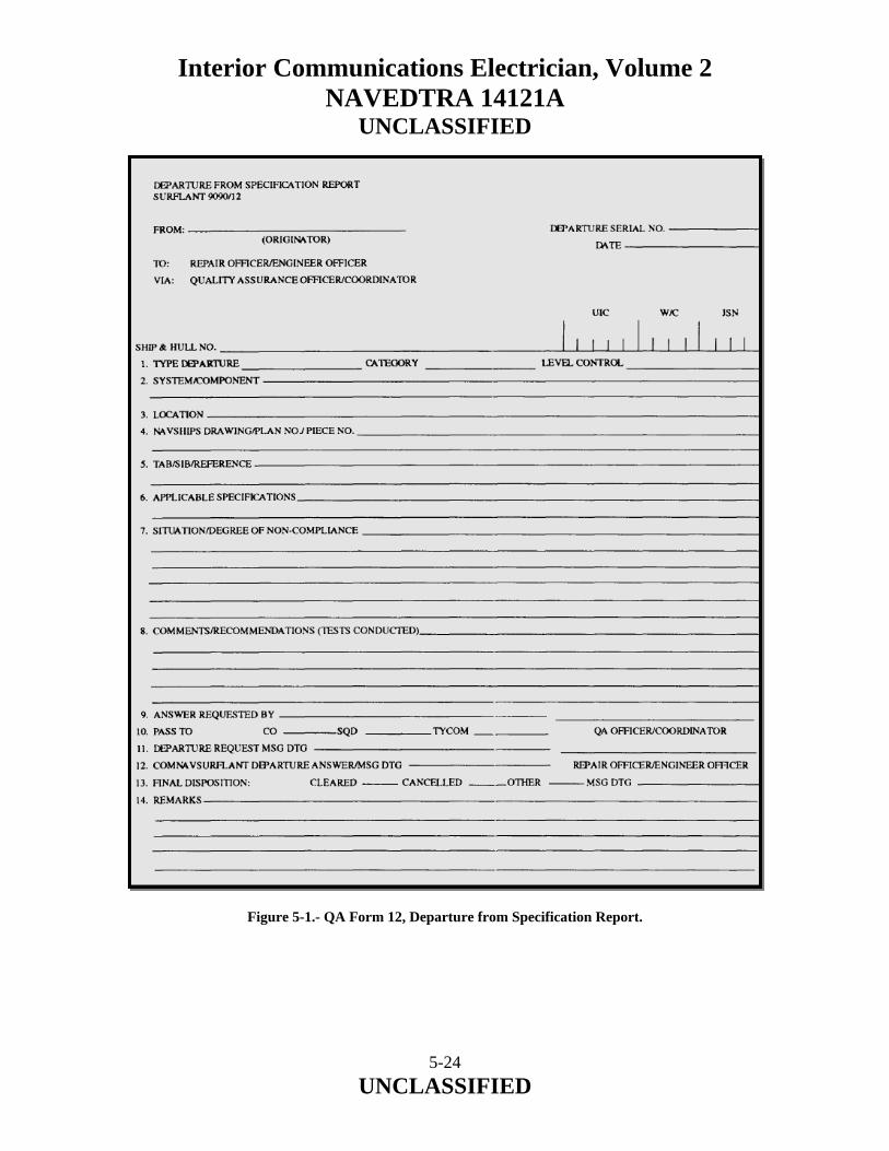
Interior Communications Electrician, Volume 2 NAVEDTRA 14121A
UNCLASSIFIED Figure 5-1.- QA Form 12, Departure from Specification Report.
5-24 UNCLASSIFIED

Interior Communications Electrician, Volume 2 NAVEDTRA 14121A
UNCLASSIFIED The originator must also retain a copy of the prepared departure request until he or she receives the returned copy from the QAO indicating that all actions concerning the departure have been completed (approved or disapproved). Make sure that the originator has an approved copy of the departure request accompanying the completed work and that the original copy is retained in the CWP. 5.10.0 QUALITY ASSURANCE FORMS AND RECORDS The following are the titles and descriptions of the forms and records you will use the most. A rule to remember when using these forms is that all QA forms must be completed and signed in the proper sequence. QA FORM 1, MATERIAL RECEIPT CONTROL RECORD This record (fig. 5-2) is used by the CMPO to document the proper receipt and inspection of items that have been designated as controlled materials. Figure 5-2.- QA Form 1, Material Receipt Control Record. QA FORM 2, MATERIAL IN-PROCESS CONTROL TAG This tag (fig. 5-3) is attached by supply, QA, or shop personnel to provide traceability of accepted controlled material from receipt inspection through final acceptance.
5-25 UNCLASSIFIED

Interior Communications Electrician, Volume 2 NAVEDTRA 14121A
UNCLASSIFIED
Figure 5-3.- QA Form 2, Material In-Process Control Tag. QA FORM 3, CONTROLLED MATERIAL REJECT TAG Shop personnel, supply, or QA personnel will attach this tag (fig. 5-4) to rejected items. The individual finding or causing the unacceptable condition attaches the tag to the rejected item. The tag indicates that material is unacceptable for production work and must be replaced or re-inspected before use.
5-26 UNCLASSIFIED

Interior Communications Electrician, Volume 2 NAVEDTRA 14121A
UNCLASSIFIED
Figure 5-4.- QA Form 3, Controlled Material Reject Tag. QA FORM 4, CONTROLLED MATERIAL SHIP-TO-SHOP TAG This tag (fig. 5-5) is used to identify and control material to be repaired. You attach the tag to the item to be repaired. It is a good idea to stamp the three sections of the tag with a control number and log it in your shop log.
5-27 UNCLASSIFIED

Interior Communications Electrician, Volume 2 NAVEDTRA 14121A
UNCLASSIFIED
Figure 5-5.- QA Form 4, Controlled Material Ship-to-Shop Tag.
5-28 UNCLASSIFIED

Interior Communications Electrician, Volume 2 NAVEDTRA 14121A
UNCLASSIFIED A FORM 4A, SHIP-TO-SHOP TAG (GENERAL USE) This tag is used to identify and control material and equipment in a positive manner from ship to repair shop. This tag does not require a material control number. Instead it uses an equipment serial number, a job sequence number, and, if possible, a Navy standard stock number for maintaining positive control. QA FORM 7, CONTROLLED MATERIAL INVENTORY/RECORD This form (fig. 5-6) is used by your CMPO to provide a standard inventory record of controlled material received and issued. Figure 5-6.- QA Form 7, Controlled Material Inventory/Record. QA FORM 8, PRODUCTION TASK CONTROL FORM This form (fig. 5-7) is used to standardize the format used for abbreviated and detailed production tasks for level 1, level A, and level B controlled work.
5-29 UNCLASSIFIED
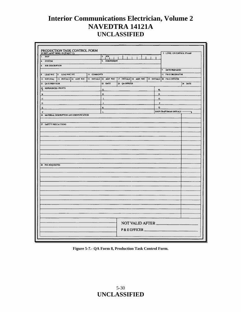
Interior Communications Electrician, Volume 2 NAVEDTRA 14121A
UNCLASSIFIED Figure 5-7.- QA Form 8, Production Task Control Form.
5-30 UNCLASSIFIED
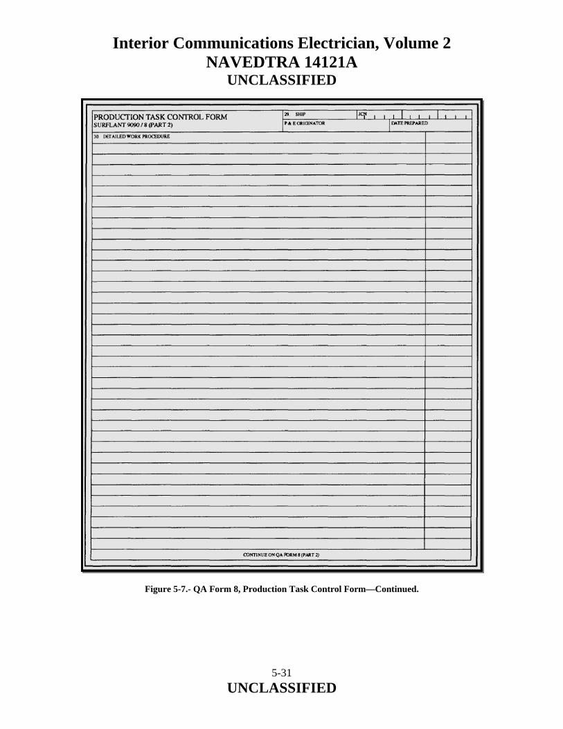
Interior Communications Electrician, Volume 2 NAVEDTRA 14121A
UNCLASSIFIED
Figure 5-7.- QA Form 8, Production Task Control Form—Continued.
5-31 UNCLASSIFIED
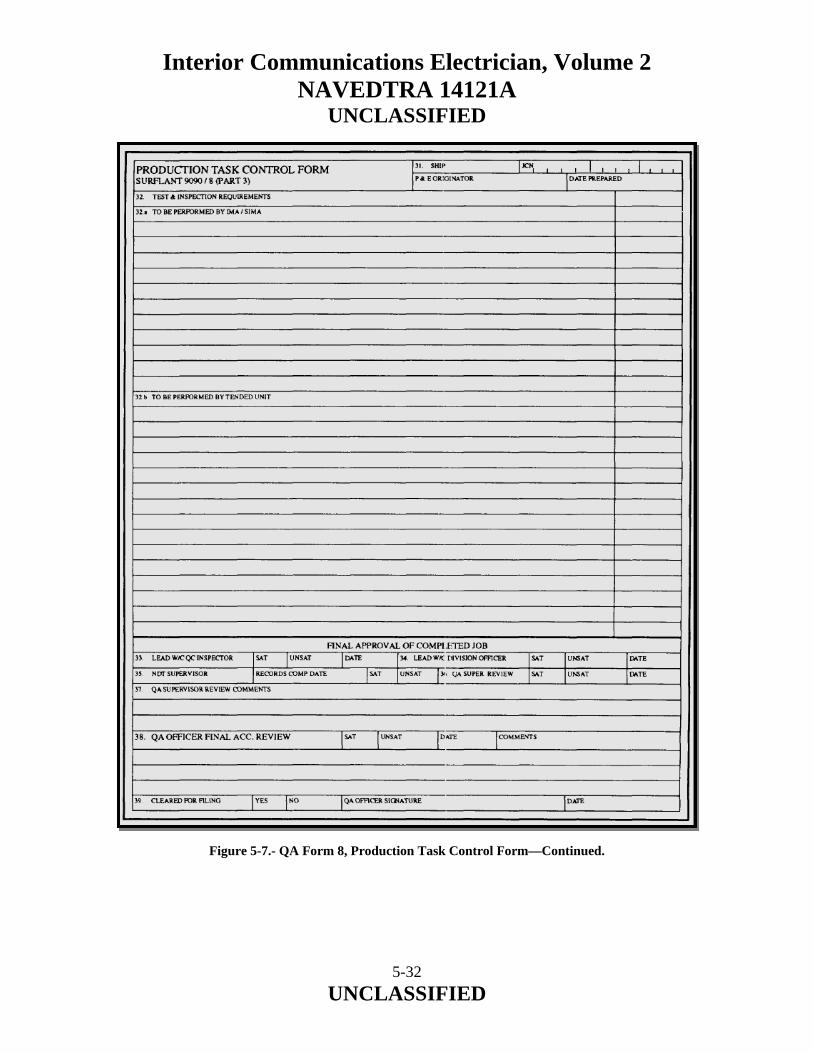
Interior Communications Electrician, Volume 2 NAVEDTRA 14121A
UNCLASSIFIED
Figure 5-7.- QA Form 8, Production Task Control Form—Continued.
5-32 UNCLASSIFIED

Interior Communications Electrician, Volume 2 NAVEDTRA 14121A
UNCLASSIFIED QA FORM 8A, MATERIAL REQUIREMENTS (CONTROLLED WORK PACKAGE ONLY) This form is used to provide a list of required materials necessary to complete the work described on the OPNAV 479W2K, 4790/2R, and the QA Form 8. QA FORM 9, RE-ENTRY CONTROL FORM This form (fig. 5-8) is used to document re-entry into a SUBSAFE boundary and is used in a controlled work procedure.
Figure 5-8.- QA Form 9, Re-Entry Control Form.
5-33 UNCLASSIFIED
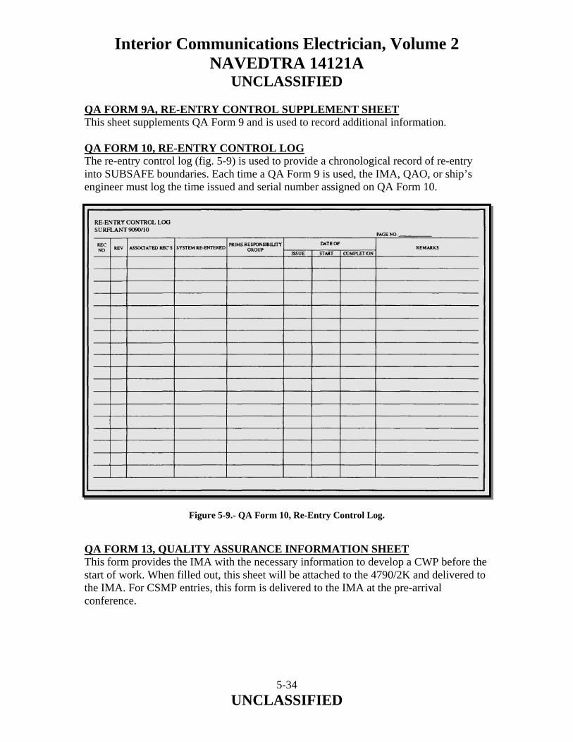
Interior Communications Electrician, Volume 2 NAVEDTRA 14121A
UNCLASSIFIED QA FORM 9A, RE-ENTRY CONTROL SUPPLEMENT SHEET This sheet supplements QA Form 9 and is used to record additional information. QA FORM 10, RE-ENTRY CONTROL LOG The re-entry control log (fig. 5-9) is used to provide a chronological record of re-entry into SUBSAFE boundaries. Each time a QA Form 9 is used, the IMA, QAO, or ship’s engineer must log the time issued and serial number assigned on QA Form 10. Figure 5-9.- QA Form 10, Re-Entry Control Log. QA FORM 13, QUALITY ASSURANCE INFORMATION SHEET This form provides the IMA with the necessary information to develop a CWP before the start of work. When filled out, this sheet will be attached to the 4790/2K and delivered to the IMA. For CSMP entries, this form is delivered to the IMA at the pre-arrival conference.
5-34 UNCLASSIFIED

Interior Communications Electrician, Volume 2 NAVEDTRA 14121A
UNCLASSIFIED QA FORM 15, REQUEST FOR RELEASE OF REJECTED MATERIAL OR WORKMANSHIP Should there be an urgent and overriding requirement for the use of material or workmanship, the division officer/production officer may request that the repair officer and squadron material officer release rejected material or workmanship. For example, a shaft has been machined undersize, but it is determined that this condition will have little or no effect on the equipment operation. If the release is authorized, the reject tag and the Material Deficiency Report (QA Form 16) must be filed in the QA office files, along with the completely filled out QA form 15. Then, the released material may be used, but one of the following three actions must be completed before the certification tiles are completed.
• Material released for use and action complete • Material released for use but must be re-worked at a later date • Material released for use but must be replaced at a later date
The use of QA Form 15 (fig. 5-10) requires the initiation of QA Form 12, Departure from Specifications Request.
5-35 UNCLASSIFIED

Interior Communications Electrician, Volume 2 NAVEDTRA 14121A
UNCLASSIFIED
Figure 5-10.- QA Form 15, Request for Release of Rejected Material or Workmanship.
5-36 UNCLASSIFIED

Interior Communications Electrician, Volume 2 NAVEDTRA 14121A
UNCLASSIFIED QA FORM 16, MATERIAL DEFICIENCY REPORT This form (fig. 5-11) is used to provide a uniform method of reporting and recommending disposition of rejected material to the supply department. It is used where required to supplement QA Form 3 and instead of QA Form 15. The report contains a descriptive statement of material for a job order within the scope of this program and includes necessary sketches, photographs, samples, and blueprints. This report recommends a course of action. Figure 5-11.- QA Form 16, Material Deficiency Report.
5-37 UNCLASSIFIED
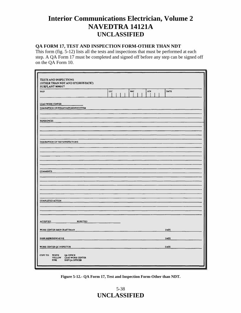
Interior Communications Electrician, Volume 2 NAVEDTRA 14121A
UNCLASSIFIED QA FORM 17, TEST AND INSPECTION FORM-OTHER THAN NDT This form (fig. 5-12) lists all the tests and inspections that must be performed at each step. A QA Form 17 must be completed and signed off before any step can be signed off on the QA Form 10. Figure 5-12.- QA Form 17, Test and Inspection Form-Other than NDT.
5-38 UNCLASSIFIED

Interior Communications Electrician, Volume 2 NAVEDTRA 14121A
UNCLASSIFIED
5-39 UNCLASSIFIED
5.11.0 SUMMARY In this chapter, we have described the purpose and goal of the Quality Assurance (QA) program. We have identified and discussed the chain of command for a QA program and the responsibilities of personnel in the chain of command. We have described QA personnel qualification requirements and described the operation of a QA program as well as identify the definitions of terms used in QA. We have identified the purpose of tests and inspections associated with the QA program, described the responsibilities of personnel conducting tests and inspections and discussed the requirements and procedures in conducting a QA program inspection and the contents and format of various QA forms and reports.
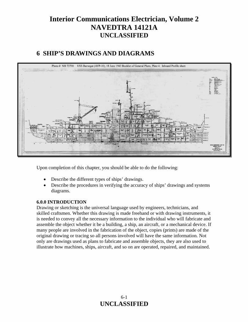
Interior Communications Electrician, Volume 2 NAVEDTRA 14121A
UNCLASSIFIED
6 SHIP’S DRAWINGS AND DIAGRAMS Upon completion of this chapter, you should be able to do the following:
• Describe the different types of ships’ drawings. • Describe the procedures in verifying the accuracy of ships’ drawings and systems
diagrams. 6.0.0 INTRODUCTION Drawing or sketching is the universal language used by engineers, technicians, and skilled craftsmen. Whether this drawing is made freehand or with drawing instruments, it is needed to convey all the necessary information to the individual who will fabricate and assemble the object whether it be a building, a ship, an aircraft, or a mechanical device. If many people are involved in the fabrication of the object, copies (prints) are made of the original drawing or tracing so all persons involved will have the same information. Not only are drawings used as plans to fabricate and assemble objects, they are also used to illustrate how machines, ships, aircraft, and so on are operated, repaired, and maintained.
6-1 UNCLASSIFIED

Interior Communications Electrician, Volume 2 NAVEDTRA 14121A
UNCLASSIFIED The chapter contains general information about the various types of ships’ drawing and system diagrams that you should be familiar with as an IC1 or ICC. They include the following:
• Blueprints • Electrical prints • Electronic prints • Electromechanical drawings • Logic diagrams
As an IC1 or ICC, you should have an in depth knowledge of how to use, care for, update, and verify the accuracy of these drawings. Drawings have a variety of uses, and you, as a supervisor, will come to realize the importance of drawings. 6.1.0 BLUEPRINTS Blueprints are reproduced copies of mechanical or other types of technical drawings. The term blueprint reading means interpreting the ideas expressed by others on drawings. Whether the drawings are actually blueprints or not. 6.1.1 How Prints Are Made A mechanical drawing is drawn with instruments such as compasses, ruling pens, T-squares, triangles, and french curves. Prints (copies) are reproduced from original drawings in much the same manner as photographic prints are reproduced from negatives. The original drawings for prints are made by drawing directly on, or tracing, a drawing on a translucent tracing paper or cloth, using black waterproof (india) ink or a drawing pencil. This original drawing is normally called a tracing “master copy.” These copies of the tracings are rarely, if ever, sent to a shop or job site. Instead, reproductions of these tracings are made and distributed to persons or offices where needed. These tracings can be used over and over indefinitely if properly handled and stored. Blueprints are made from these tracings. The term blueprints is a rather loosely used term in dealing with reproductions of original drawings. One of the first processes devised to reproduce prints or duplicate tracings produced white lines on a blue background, hence the term blueprints. Today, however, other methods of reproduction have been developed, and they produce prints of different colors. The colors may be brown, black, gray, or maroon. The differences are the types of paper and the developing processes used.
6-2 UNCLASSIFIED

Interior Communications Electrician, Volume 2 NAVEDTRA 14121A
UNCLASSIFIED A patented paper identified as BW paper produces prints with black lines on a white background. The ammonia process, or OZALIDS, produces prints with either black blue, or maroon lines on a white background. Other processes that may be used to reproduce drawings, usually small drawings or sketches, are the office-type duplicating machines, such as the mimeograph and ditto machines. One other type of duplicating process rarely used for reproducing working drawings is the photostatic process in which a large camera reduces or enlarges a tracing or drawing. The photostat has white lines on a dark background when reproduced directly from a tracing or drawing. If the photostated print is then reproduced, it will have brown lines on a white background. Photostats are generally used by various businesses for incorporating reduced-size drawings into reports or records. Military drawings and blueprints are prepared according to the prescribed standards and procedures in military standards (MIL-STDS). These MIL-STDS are listed in the Department of Defense Index of Specifications and Standards, issued as of 31 July of each year. Common MIL-STDS concerning engineering drawings and blueprints most commonly used by IC Electricians are listed by number and title as follows: NUMBER TITLE MIL-STD-100E Engineering Drawing Practices MIL-STD-12D Abbreviations For Use On Drawings ANSI Y32.2 Graphic Symbols For Electrical and Electronics Diagrams MIL-STD-15 Part No. 2 Electrical Wiring Equipment Symbols For Ships Plans, Part 2 ANSI Y32.9 Electrical Wiring Symbols For Architectural and Electrical Layout Drawings MIL-STD-16C Electrical and Electronic Reference Designations MIL-STD-25A Nomenclature and Symbols For Ship Structure
6-3 UNCLASSIFIED

Interior Communications Electrician, Volume 2 NAVEDTRA 14121A
UNCLASSIFIED 6.1.2 Parts of a Blueprint Military blueprints are prepared as to size, format, location of, information included in various blocks, and so on, according to MIL-STD-100E of 30 September 1991. The various parts of a blueprint are described briefly in the following paragraphs. Title Block The Title block is located in the lower right-hand corner of all blueprints and drawings prepared according to MIL-STDs. The block contains the drawing number, the name of the part or assembly that the blueprint represents, and all information required to identify the part or assembly. The Title block also includes the name and address of the government agency or organization preparing the drawing, the scale, drafting record, authentication, and the date (fig. 6-1). A space within the Title block with a diagonal or slant line drawn across it (not shown in fig. 6-1) indicates that the information usually placed in it is not required or is given elsewhere on the drawing. Revision Block The Revision block (not shown) is usually located in the upper right-hand comer of the blueprint and is used for the recording of changes (revisions) to the print. All revisions are noted in this block and are dated and identified by a letter and a brief description of the revision. A revised drawing is shown by the addition of a letter to the original number, as shown in figure 6-1, view A. If the print shown in figure 6-1, view A, was again revised, the letter A in the Revision block would be replaced by the letter B. Drawing Number All blueprints are identified by a drawing number (NAVSHIP Systems Command number, fig. 6-1, view A, and Naval Facilities Engineering Command drawing number, fig. 6-1, view B), which appears in a block. It may be shown in other places also; for example, near the top border line in the upper comer, or on the reverse side at both ends so it will be visible when a drawing is rolled up. If a blueprint has more than one sheet, this information is included in the Number block indicating the sheet number and the number of sheets in the series. For example, note that in the Title block shown in figure 6-1, the sheet is sheet 1 of 1.
6-4 UNCLASSIFIED
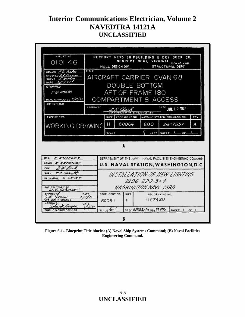
Interior Communications Electrician, Volume 2 NAVEDTRA 14121A
UNCLASSIFIED Figure 6-1.- Blueprint Title blocks: (A) Naval Ship Systems Command; (B) Naval Facilities
Engineering Command.
6-5 UNCLASSIFIED
Interior Communications Electrician, Volume 2 NAVEDTRA 14121A
UNCLASSIFIED Reference Numbers Reference numbers that appear in the title block refer to the number of other blueprints. When more than one detail is shown on a drawing, a dash and a number are frequently used. For example, if two parts are shown in one detail drawing, both prints would have the same drawing number, plus a dash and an individual number, such as 8117041-1 and 8117041-2. In addition to appearing in the Title block, the dash and number may appear on the face of the drawings near the parts they identify. Some commercial prints show the drawing and dash number and carry a leader line to the part; others use a circle, 3/8 inch in diameter around the dash number and carry a leader line to the point. A dash and number are used to identify modified or improved parts and to identify right-hand and left-hand parts. Many parts on the right side of a piece of equipment are identical to the parts on the left side–in reverse. The left-hand part is usually shown in the drawing. Above the Title block on some prints, you may see a notation such as 159674 LH shown; 159674-1 RH opposite. Both parts carry the same number, but the part called for is distinguished by a dash and number. (LH means left hand and RH means right hand.) Some companies use odd numbers for right-hand parts and even numbers for left-hand parts. Zone Numbers Zone numbers on blueprints serve the same purpose as the numbers and letters printed on borders of maps to help you locate a particular point. To find a particular point, mentally draw horizontal and vertical lines from these letters and numerals. The point where these lines intersect is the particular point sought. You will use practically the same system to help you locate parts, sections, and views on large blueprinted objects (for example, assembly drawings on ships’ steering gear). Parts numbered in the Title block can be located on the drawing by looking up the numbers in squares along the lower border. Zone numbers read from right to left.
6-6 UNCLASSIFIED

Interior Communications Electrician, Volume 2 NAVEDTRA 14121A
UNCLASSIFIED Scale The scale of the blueprint is indicated in one of the spaces within the Title block It indicates the size of the drawing as compared with the actual size of the part. The scale may be shown as 1" = 2", 1" = 12", 1/2" = 1', and so on. It also maybe indicated as full size, one-half size, one-fourth size, and so on. If a blueprint indicates that the scale is 1" = 2", each line on the print is shown one-half its actual length. If a blueprint indicates that the scale is 3" = 1", each line on the print is three times its actual length. Very small parts are enlarged to show the views clearly, and large objects are normally reduced in size to tit on standard size drawing paper. In short, the scale is selected to fit the object being drawn and the space available on a sheet of drawing paper. Remember: NEVER MEASURE A DRAWING. USE DIMENSIONS. Why? Because the print may have been reduced in size from the original drawing, or you might not take the scale of the drawing into consideration. Then too, paper stretches and shrinks as humidity changes, thus introducing perhaps the greatest source of error in actually taking a measurement by laying a rule on the print itself. Play it safe and READ the dimensions on the drawing; they always remain the same. Graphical scales are often placed on maps and plot plans. These scales indicate the number of feet or miles represented by an inch. A fraction is often used, such as 1/500, meaning that one unit on the map is equal to 500 like units on the ground. A LARGE-SCALE MAP has a scale of 1" = 10"; a map with a scale of 1" = 1,000' is considered a SMALL-SCALE MAP. Various types and shapes of scales are used in preparing blueprints. Four common types are shown in figure 6-2. ARCHITECTS’ SCALES.– Architects’ scales (fig. 6-2, view A) are divided into proportional feet and inches and are generally used in scaling drawings for machine and structural work. The triangular architects’ scale usually contains 11 scales, each subdivided differently. Six scales read from the left end while five scales read from the right end. Figure 6-2, view A, shows how the 3/16-inch subdivision of the architects’ scale is further subdivided into 12 equal parts representing 1 inch each, and the 3/32-inch subdivision is further subdivided into 6 equal parts representing 2 inches each.
6-7 UNCLASSIFIED
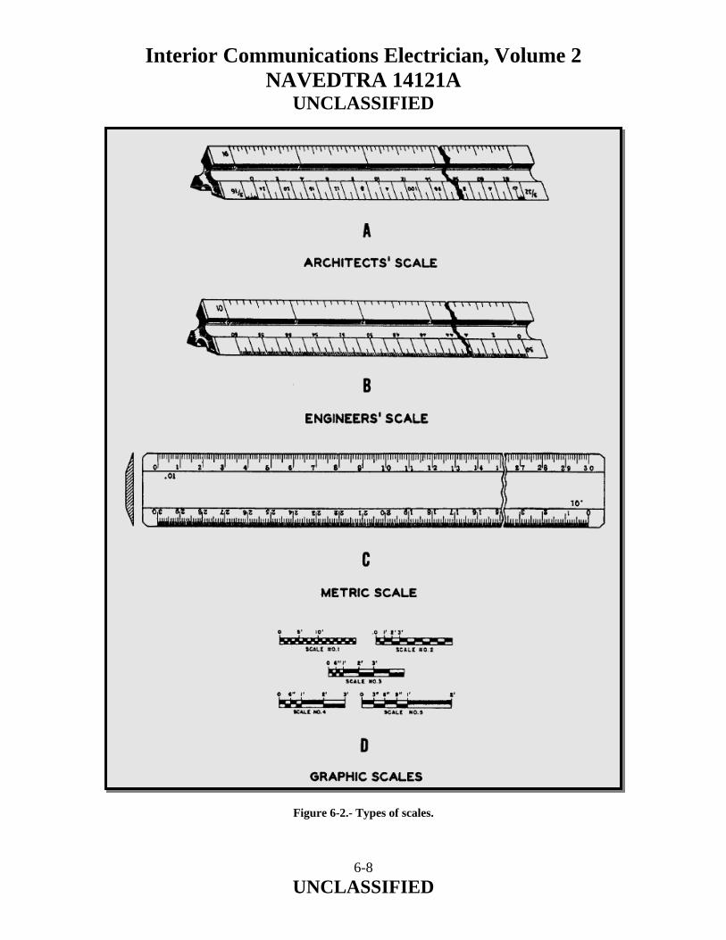
Interior Communications Electrician, Volume 2 NAVEDTRA 14121A
UNCLASSIFIED Figure 6-2.- Types of scales.
6-8 UNCLASSIFIED

Interior Communications Electrician, Volume 2 NAVEDTRA 14121A
UNCLASSIFIED ENGINEERS’ SCALES.– Engineers’ scales (fig. 6-2, view B) are divided into decimal graduations (10, 20, 30, 40, 50, and 60 divisions to the inch). These scales are used for plotting and map drawing and in the graphic solution of problems. METRIC SCALES.– Metric scales (fig. 6-2, view C) are used with the drawings, maps, and so forth, made in countries using the metric system. This system is also being used with increasing frequency in the United States. The scale is divided into centimeters (cm) and millimeters (mm). In conversion, 2.54 cm are equal to 1 inch. GRAPHIC SCALES.– Graphic scales (fig. 6-2, view D) are lines subdivided into distances corresponding to convenient units of length on the ground or of the object represented by the blueprint. They are placed in or near the Title block of the drawing and their relative lengths to the scales of the drawing are not affected if the print is reduced or enlarged. Bill of Material Block The Bill of Material block on a blueprint contains a list of the parts and materials used on or required by the print concerned. The block identifies parts and materials by stock number or other appropriate number and lists the quantity used or required. The Bill of Material block often contains a list of standard parts, known as a parts list or schedule. Many commonly used items, such as machine bolts, screws, turnbuckles, rivets, pipefittings, and valves, have been standardized by the military. A Bill of Material block for an electrical plan is shown in figure 6-3. Figure 6-3.- Bill of Material block.
6-9 UNCLASSIFIED
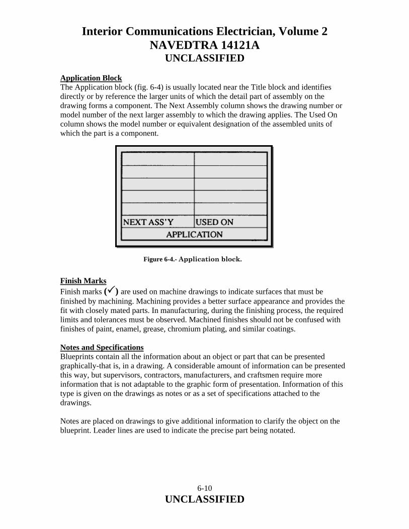
Interior Communications Electrician, Volume 2 NAVEDTRA 14121A
UNCLASSIFIED Application Block The Application block (fig. 6-4) is usually located near the Title block and identifies directly or by reference the larger units of which the detail part of assembly on the drawing forms a component. The Next Assembly column shows the drawing number or model number of the next larger assembly to which the drawing applies. The Used On column shows the model number or equivalent designation of the assembled units of which the part is a component.
Figure 6-4.- Application block. Finish Marks Finish marks ( ) are used on machine drawings to indicate surfaces that must be finished by machining. Machining provides a better surface appearance and provides the fit with closely mated parts. In manufacturing, during the finishing process, the required limits and tolerances must be observed. Machined finishes should not be confused with finishes of paint, enamel, grease, chromium plating, and similar coatings. Notes and Specifications Blueprints contain all the information about an object or part that can be presented graphically-that is, in a drawing. A considerable amount of information can be presented this way, but supervisors, contractors, manufacturers, and craftsmen require more information that is not adaptable to the graphic form of presentation. Information of this type is given on the drawings as notes or as a set of specifications attached to the drawings. Notes are placed on drawings to give additional information to clarify the object on the blueprint. Leader lines are used to indicate the precise part being notated.
6-10 UNCLASSIFIED

Interior Communications Electrician, Volume 2 NAVEDTRA 14121A
UNCLASSIFIED A specification is a statement or document containing a description or enumeration of particulars, as the terms of a contract or details of an object or objects not shown on a blueprint or drawing. Specifications (specs) describe items so they may be procured, assembled, and maintained to function according to the performance requirements; furnish sufficient information to permit determination of conformance to the description; and furnish the information in accomplishment sufficient completeness for without the need of research, development, design engineering, or help from the preparing organization. Federal specifications cover the characteristics of material and supplies used jointly by the Navy and other government departments. All federal specifications used by the Navy Department as purchase specifications are listed in the Department of Defense Index of Specifications and Standards. Legend or Symbols The legend, if used, is placed on the upper right-hand corner of a blueprint below the Revision block. The legend explains or defines a symbol or special mark placed on a blueprint. Figure 6-5 shows a legend for an electrical plan. Figure 6-5.- An electrical plan.
6-11 UNCLASSIFIED
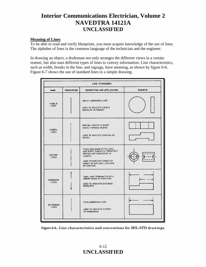
Interior Communications Electrician, Volume 2 NAVEDTRA 14121A
UNCLASSIFIED Meaning of Lines To be able to read and verify blueprints, you must acquire knowledge of the use of lines. The alphabet of lines is the common language of the technician and the engineer. In drawing an object, a draftsman not only arranges the different views in a certain reamer, but also uses different types of lines to convey information. Line characteristics, such as width, breaks in the line, and zigzags, have meaning, as shown by figure 6-6. Figure 6-7 shows the use of standard lines in a simple drawing.
Figure 6-6.- Line characteristics and conventions for MIL-STD drawings.
6-12 UNCLASSIFIED
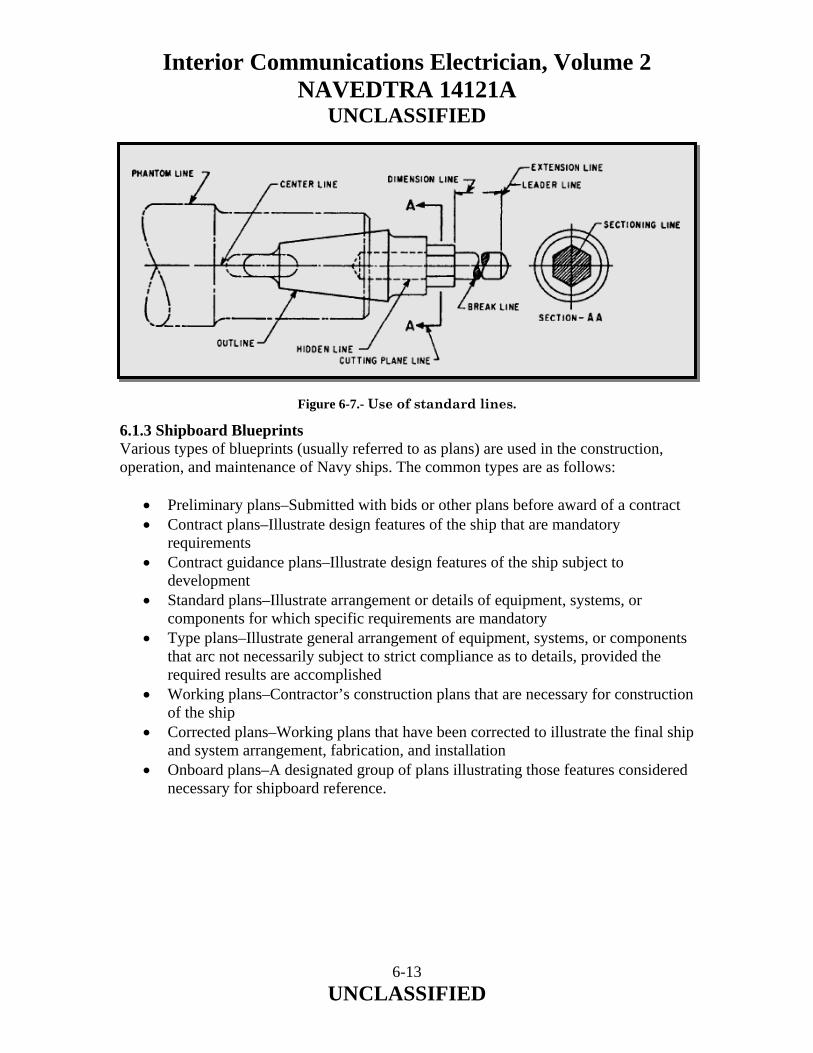
Interior Communications Electrician, Volume 2 NAVEDTRA 14121A
UNCLASSIFIED
Figure 6-7.- Use of standard lines. 6.1.3 Shipboard Blueprints Various types of blueprints (usually referred to as plans) are used in the construction, operation, and maintenance of Navy ships. The common types are as follows:
• Preliminary plans–Submitted with bids or other plans before award of a contract • Contract plans–Illustrate design features of the ship that are mandatory
requirements • Contract guidance plans–Illustrate design features of the ship subject to
development • Standard plans–Illustrate arrangement or details of equipment, systems, or
components for which specific requirements are mandatory • Type plans–Illustrate general arrangement of equipment, systems, or components
that arc not necessarily subject to strict compliance as to details, provided the required results are accomplished
• Working plans–Contractor’s construction plans that are necessary for construction of the ship
• Corrected plans–Working plans that have been corrected to illustrate the final ship and system arrangement, fabrication, and installation
• Onboard plans–A designated group of plans illustrating those features considered necessary for shipboard reference.
6-13 UNCLASSIFIED

Interior Communications Electrician, Volume 2 NAVEDTRA 14121A
UNCLASSIFIED 6.1.4 Handling Blueprints Blueprints are valuable permanent records that can be used over and over if necessary. However, if you are to keep these prints as permanent records, you must handle them with care. Here are a few simple rules to follow to preserve these prints:
• Keep prints out of strong sunlight because they will fade. • Do not allow prints to become wet or smudged with oil or grease. Oil and grease
seldom dry out completely; therefore, if the prints become wet or smudged with oil or grease, they become practically useless.
• Do not make pencil or crayon notations on a print without proper authority. If you receive instructions to mark a print, use an appropriate colored pencil and make the markings a permanent part of the print. Yellow is a good color to use on a print with a blue background (blueprint).
• Keep prints stowed in their proper place so they can be readily located the next time you want to refer to them.
Most of the prints you will handle will be received properly folded. Your main concern will be to refold them correctly. You may, however, have occasion to receive prints that have not been folded at all or that have been folded improperly. The method of folding prints depends upon the type and size of the filing cabinet and the location of the identifying marks on the prints. It is preferable to place identifying marks at the top of prints when filing them vertically and at the bottom right-hand corner when filing (hem flat. In some cases, construction prints are stored in rolls. 6.2.0 ELECTRICAL PRINTS Navy electrical prints are used by the IC Electrician in the installation, maintenance, and repair of shipboard electrical equipment and systems. These prints include various types of electrical diagrams as defined in the following paragraphs. PICTORIAL WIRING DIAGRAM–A diagram that shows actual pictorial sketches of the various parts of a piece of equipment and the electrical connections between the parts. ISOMETRIC WIRING DIAGRAM–A diagram that shows the outline of a ship or aircraft or other structure and the location of equipment, such as panels and connection boxes and cable run. WIRING (CONNECTION) DIAGRAM–A diagram that shows the individual connections within a unit and the physical arrangement of the components.
6-14 UNCLASSIFIED

Interior Communications Electrician, Volume 2 NAVEDTRA 14121A
UNCLASSIFIED SCHEMATIC DIAGRAM–A diagram that uses graphic symbols to show how a circuit functions electrically. ELEMENTARY WIRING DIAGRAM–(1) A shipboard wiring diagram that shows how each conductor is connected within the various connection boxes of an electrical circuit or system. (2) A schematic diagram; the term elementary wiring diagram is sometimes used interchangeably with schematic diagram, especially a simplified schematic diagram. BLOCK DIAGRAM–A diagram in which the major components of a piece of equipment or system are represented by squares, rectangles, or other geometric figures, and the normal order of progression of a signal or current flow is represented by lines. SINGLE-LINE DIAGRAM–A diagram that uses single lines and graphic symbols to simplify a complex circuit or system. To be able to read and verify the accuracy of any type of blueprint, you must be familiar with the standard symbols used for the type of print concerned. Reading electrical blueprints requires knowledge of various types of standard symbols and, in addition, knowledge of the methods of marking electrical conductors, cables, and equipments. 6.2.1 Shipboard Electrical Prints Various types of electrical drawings and diagrams are used in the installation and maintenance of shipboard electrical circuits, systems, and components. To interpret shipboard electrical prints, you must be able to recognize the graphic symbols for electrical diagrams and the electrical wiring equipment symbols for ships as shown in ANSI/IEEE STD 315A-1986 and MIL-STD-15-2. Common symbols from these standards are shown in table 6-1. In addition, you must also be familiar with the shipboard system of numbering electrical units and marking electrical cables as described in the following paragraphs.
6-15 UNCLASSIFIED
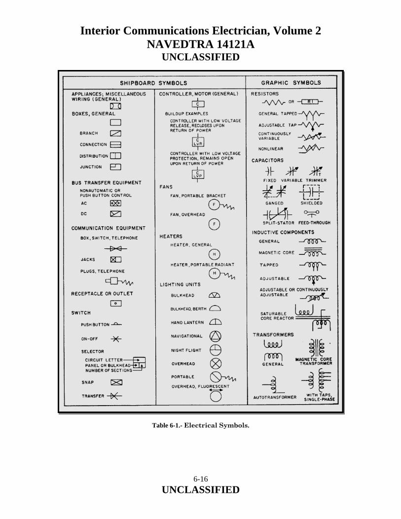
Interior Communications Electrician, Volume 2 NAVEDTRA 14121A
UNCLASSIFIED
Table 6-1.- Electrical Symbols.
6-16 UNCLASSIFIED
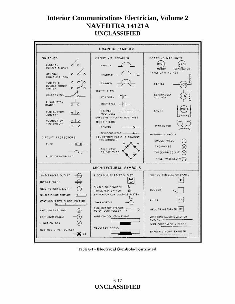
Interior Communications Electrician, Volume 2 NAVEDTRA 14121A
UNCLASSIFIED
Table 6-1.- Electrical Symbols-Continued.
6-17 UNCLASSIFIED

Interior Communications Electrician, Volume 2 NAVEDTRA 14121A
UNCLASSIFIED 6.2.2 Numbering Electrical Units Electrical units and other shipboard machinery and equipment are numbered as described in the following paragraphs. All similar units in the ship comprise a group, and each group is assigned a separate series of consecutive numbers beginning with 1. Numbering begins in the lowest foremost starboard compartment, and the next compartment selected is to port of the first if it contains similar units; otherwise, the next aft on the same level. Proceeding from starboard to port and from forward to aft, the numbering procedure continues until all similar units on the same level have been numbered; then it continues on the next upper level, and so on, until all similar units on all levels have been numbered. Within each compartment, the numbering of similar units proceeds from starboard to port, forward to aft, and from a lower to a higher level. Within a given compartment, then, the numbering of similar units follows the same rule; that is, lower takes precedence over aft, and starboard takes precedence over port. Electrical distribution panels, control panels, and so on, are given identification numbers made up of three numbers separated by hyphens. The first number indicates the vertical level, at which the unit is normally accessible, by deck or platform number. Decks of Navy ships are numbered using the main deck as the starting point. The numeral 1 is used for the main deck. Each successive deck above the main deck is numbered 01, 02, 03, and so on, and each successive deck below the main deck is numbered 2, 3, 4, and so on. The second number indicates the longitudinal location of the unit by frame number. The third number indicates the transverse location by the assignment of consecutive odd numbers for centerline and starboard locations and consecutive even numbers for port locations. The numeral 1 indicates the lowest centerline (or centermost) starboard component. Consecutive odd nun numbers are assigned components as they would be observed first as being above and then outboard of the preceding component. Consecutive even numbers similarly indicate components on the port side. For example, a distribution panel with the identification number 1-142-2 will be located on the main deck at frame 142 and will be the first distribution panel on the port side of the centerline at this frame on the main deck.
6-18 UNCLASSIFIED

Interior Communications Electrician, Volume 2 NAVEDTRA 14121A
UNCLASSIFIED Main switchboards or switchgear groups supplied directly from ship’s service generators are designated 1S, 2S, 3S, and soon, as necessary to designate all ship’s service switchboards. Switchboards supplied directly by emergency generators are designated 1E, 2E, 3E, and so on, as necessary to designate all emergency switchboards. Switchboards for special frequency (other than the frequency of the ship’s service system) have ac generators designated 1SF, 2SF, and so on, as necessary to designate all special frequency switchboards. 6.2.3 Cable Marking Metal tags embossed with the cable designation are used to identify all permanently installed shipboard electrical cables. These tags (fig. 6-8) are placed on cables as close as practicable to each point of connection, on both sides of decks, bulkheads, and other barriers to provide identification of the cables for maintenance and replacement.
Figure 6-8.- Cable tag. Two systems of cable marking (the old and the new) are in use aboard Navy ships. The old system uses the color of the tag to show cable classification (red-vital, yellow–semivital, and gray or no color–nonvital), and the following letters to designate power and lighting cables for the different services:
C–Interior communications D–Degaussing F–Ship’s service lighting and general power FB–Battle power G–Fire control MS–Minesweeping P–Electric propulsion R–Radio and radar RL–Running, anchor, and signal lights S–Sonar FE–Emergency light and power
6-19 UNCLASSIFIED

Interior Communications Electrician, Volume 2 NAVEDTRA 14121A
UNCLASSIFIED Other letters and numbers are used with these basic letters to further identify the cable and complete the designation. Common marking of a power system for successive cables from a distribution switchboard to load would be feeder, FB-411; main, 1-FB-411; submain, 1-FB-411-A; branch, 1-FB-411-A1; and subbranch, 1-FB-411-A1A. The feeder number, 411, is indicative of the system voltage. The feeder numbers for a 117- or 120-volt system would range from 100 to 190; for a 220-volt system, from 200 to 299; and for a 450-volt system, from 400 to 499. The exact designation for each cable is shown on the ship’s electrical wiring prints. The new cable marking system for power and lighting cables consists of three parts in sequence: source, voltage, and service, and where practicable, destination. These parts are separated by hyphens. The letters used to designate the different services are as follows:
C–Interior communications D–Degaussing G–Fire control K–Control power L–Ship’s service lighting N–Navigational lighting P–Ship’s service power R–Electronics CP–Casualty power EL–Emergency lighting EP–Emergency power FL–Night flight MC–Coolant pump power MS–Minesweeping PP–Propulsion power SF–Special frequency power
In the new system, voltages below 100 volts are designated by the actual voltage; for example, 24 volts for a 24-volt circuit. The numeral 1 is used to indicate voltages between 100 and 199; 2 for voltages between 200 and 299; 4 for voltages between 400 and 499; and so on. For a three-wire (120/240) dc system or a three-wire 3-phase system, the number used indicates the higher voltage.
6-20 UNCLASSIFIED

Interior Communications Electrician, Volume 2 NAVEDTRA 14121A
UNCLASSIFIED The destination of cables beyond panels and switchboards is not designated except that each circuit alternately receives a letter, a number, a letter, and a number, progressively, every time that it is fused. The destination of power cables to consuming equipment is not designated except that each cable to such equipment receives a single-letter alphabetical designation, beginning with the letter A. Where two cables of the same power or lighting circuit are connected in a distribution panel or terminal box, the circuit classification is not changed. However, the cable markings have a suffix number (in parentheses) indicating the cable section. For example, (4-168-1)-4P-A (1) (fig. 6-8) identifies a 450-volt power cable supplied from a power distribution panel on the fourth deck at frame 168 starboard. The letter A indicates that this is the first cable from the panel, and the (1) indicates that it is the first section of a power main with more than one section. The power cables between generators and switchboards are labeled according to the generator designation. When only one generator supplies a switchboard, the generator will have the same number as the switchboard plus the letter G. Thus, 1SG denotes one ship’s service generator that supplies the number 1 ship’s service switchboard. When more than one ship’s service generator supplies a switchboard, the first generator determined according to the general rule for numbering machinery will have the letter A immediately following the designation; the second generator that supplies the same switchboard will have the letter B. This procedure is continued for all generators that supply the switchboards. Thus, 1SG and 1SGB denote two ship’s service generators that supply ship’s service switchboard 1S. Representative cable markings for power and lighting circuits are listed and explained in table 6-2.
6-21 UNCLASSIFIED
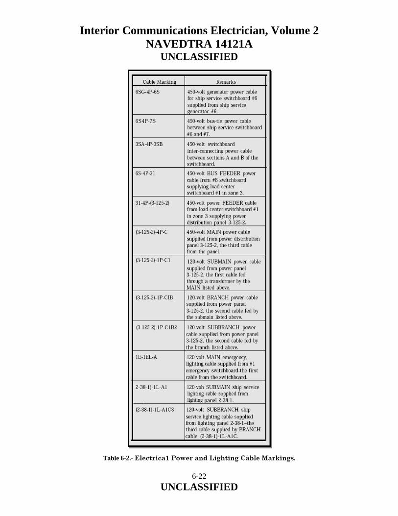
Interior Communications Electrician, Volume 2 NAVEDTRA 14121A
UNCLASSIFIED Table 6-2.- Electrica1 Power and Lighting Cable Markings.
6-22 UNCLASSIFIED

Interior Communications Electrician, Volume 2 NAVEDTRA 14121A
UNCLASSIFIED 6.2.4 Phase and Polarity Markings Phase and polarity in ac and dc electrical systems are designated by a wiring color code as shown in table 6-2. Neutral polarity, where it exists, is identified by the white conductor. 6.2.5 Isometric Wiring Diagram An isometric wiring diagram is supplied for each shipboard electrical system. If the system is not too large, the isometric wiring diagram will be covered by one blueprint. For large systems, several prints may be required to show the complete system. An isometric wiring diagram shows the ship’s decks arranged in tiers. Bulkheads and compartments are shown, the centerline is marked, and the frame numbers are shown (usually every five frames). The outer edge of each deck is drawn to show the general outline of the shape of the ship. All athwartship lines are shown at an angle of 30 degrees to the centerline. Cables running from one deck to another are drawn as lines at right angles to the centerline. A cable, regardless of the number of conductors, is represented on an isometric diagram by a single line. The various electrical fixtures are identified by a symbol number and their general location is shown. Thus, the isometric wiring diagram shows a rough picture of the entire circuit layout. 6.2.6 Wiring Deck Plan The wiring deck plan is the actual installation diagram for the deck or decks shown and is a blueprint used chiefly in ship construction. It enables the shipyard electrician to lay out the work for a number of cables without referring to each isometric wiring diagram. The plan includes a bill of material that lists all the materials and equipment necessary to complete the installation for the deck or decks concerned. Equipment and materials except cables are identified by a symbol number both on the drawing and in the bill of material. Wiring deck plans are drawn to scale (usually ¼ inch to the foot); therefore, they show the exact location of all fixtures. One blueprint usually shows from 150 to 200 feet of deck space on one deck only. Electrical wiring equipment symbols from MIL-STD-15-2 are used to represent fixtures as in the isometric wiring diagram. 6.2.7 Elementary Wiring Diagram The elementary wiring diagram shows in detail each conductor, terminal, and connection in a circuit. Elementary wiring diagrams are used to check for proper connections in a circuit or to make the initial hookup.
6-23 UNCLASSIFIED

Interior Communications Electrician, Volume 2 NAVEDTRA 14121A
UNCLASSIFIED In IC circuits, for example, the lugs on the wires to each connection box are stamped with the conductor marking. The elementary wiring diagrams show the conductor markings alongside each conductor and how they are connected in the circuit. Elementary wiring diagrams usually do not show the location of connection boxes, panels, and soon; therefore, they are not drawn to any scale. 6.2.8 Electrical Systems Diagrams Various types of electrical systems are installed aboard Navy ships that include many types of electrical devices and components. These devices and components may be located throughout the ship. The electrical diagrams and drawings necessary to operate and maintain these systems are provided by the ship’s electrical blueprints and by drawings and diagrams contained in NSTMs and manufacturers’ technical manuals. 6.2.9 Block Diagrams Block diagrams of electrical systems show the major units of the system in block form. These diagrams are used with text material to present a general description of the system and how it functions. Figure 6-9 shows a block diagram of the electrical steering system for a large ship. This diagram along with the information in the following paragraph presents the functional operation of the overall system. The steering gear system (fig. 6-9) consists of one complete synchro-controlled electric hydraulic system for each rudder (port and starboard). The two steering systems are similar in all respects. They are separate systems, but they are normally controlled by the same steering wheel (helm) and operate to move both port and starboard rudders in unison.
6-24 UNCLASSIFIED
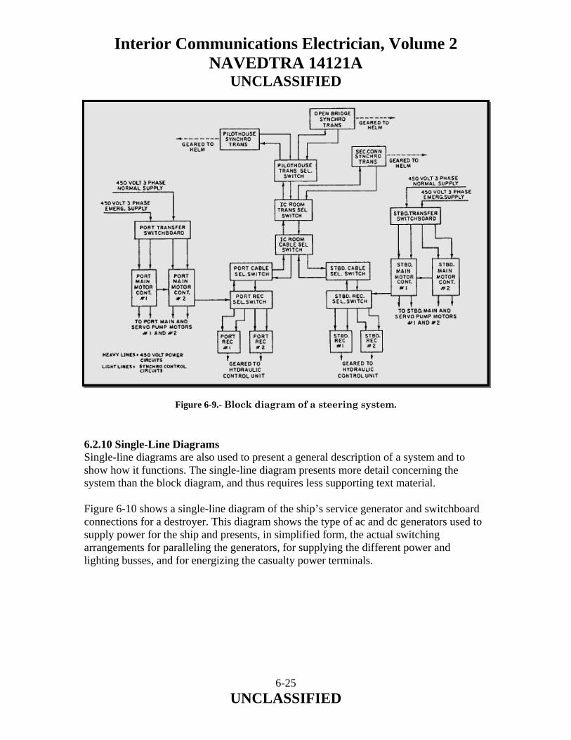
Interior Communications Electrician, Volume 2 NAVEDTRA 14121A
UNCLASSIFIED
Figure 6-9.- Block diagram of a steering system. 6.2.10 Single-Line Diagrams Single-line diagrams are also used to present a general description of a system and to show how it functions. The single-line diagram presents more detail concerning the system than the block diagram, and thus requires less supporting text material. Figure 6-10 shows a single-line diagram of the ship’s service generator and switchboard connections for a destroyer. This diagram shows the type of ac and dc generators used to supply power for the ship and presents, in simplified form, the actual switching arrangements for paralleling the generators, for supplying the different power and lighting busses, and for energizing the casualty power terminals.
6-25 UNCLASSIFIED
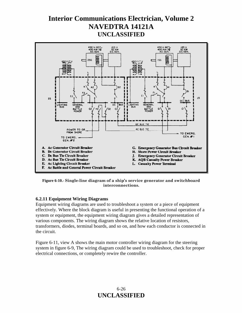
Interior Communications Electrician, Volume 2 NAVEDTRA 14121A
UNCLASSIFIED
Figure 6-10.- Single-line diagram of a ship’s service generator and switchboard interconnections.
6.2.11 Equipment Wiring Diagrams Equipment wiring diagrams are used to troubleshoot a system or a piece of equipment effectively. Where the block diagram is useful in presenting the functional operation of a system or equipment, the equipment wiring diagram gives a detailed representation of various components. The wiring diagram shows the relative location of resistors, transformers, diodes, terminal boards, and so on, and how each conductor is connected in the circuit. Figure 6-11, view A shows the main motor controller wiring diagram for the steering system in figure 6-9, The wiring diagram could be used to troubleshoot, check for proper electrical connections, or completely rewire the controller.
6-26 UNCLASSIFIED

Interior Communications Electrician, Volume 2 NAVEDTRA 14121A
UNCLASSIFIED Figure 6-11.- Main motor controller: (A) Wiring diagram; (B) Schematic.
6-27 UNCLASSIFIED

Interior Communications Electrician, Volume 2 NAVEDTRA 14121A
UNCLASSIFIED 6.2.12 Schematic Diagrams The electrical schematic diagram is used to describe the electrical operation of a particular equipment, circuit, or system. It is not drawn to scale and usually does not show the relative positions of the various components. Parts and connections not essential to understanding how the circuit operates are omitted for simplicity. Figure 6-11, view B, shows the schematic diagram for the steering system main motor controller. 6.2.13 Electronic Prints Electronic prints are similar to electrical prints. However, they are usually more difficult to read than electrical prints as they represent more complex circuitry and systems. Shipboard electronic prints include isometric wiring diagrams that show the general location of electronic units and the interconnecting cable runs, and elementary wiring diagrams that show how each cable is connected. Also included among the common types of shipboard electronic prints are block diagrams, schematic diagrams, interconnection diagrams, electromechanical drawings, and logic diagrams. The following paragraphs will discuss only those diagrams that were not discussed when we covered electrical prints. 6.2.14 Interconnection Diagrams Interconnection diagrams show the cabling between electronic units and how the units are interconnected. All terminal boards are assigned reference designations. Individual terminals on the terminal boards are assigned letters or numbers or both. 6.2.15 Electromechanical Drawings Electromechanical devices, such as synchros, gyros, accelerometers, and analog computing elements, are commonly used in IC equipment. For a complete understanding of these units, neither an electrical nor a mechanical drawing would be sufficient. Therefore, a combination type of drawing called an electromechanical drawing is used. These drawings are usually simplified both electrically and mechanically, and only those items essential to the operation are indicated on the drawing. 6.2.16 Logic Diagrams Logic diagrams are used to show the operation of logic circuits in some IC equipment. They are used in the operation and maintenance of digital computers. Graphic symbols from American Standard Y32.14 are used.
6-28 UNCLASSIFIED

Interior Communications Electrician, Volume 2 NAVEDTRA 14121A
UNCLASSIFIED
6-29 UNCLASSIFIED
Basic logic diagrams are used to show the operation of a particular unit or component. Basic logic symbols are shown in their proper relationship to show operation only in the most simplified form possible. Detailed logic diagrams show all logic functions of the equipment concerned. In addition, they also include such information as socket locations, pin numbers, and test points to facilitate troubleshooting. The detailed logic diagram for a complete unit may consist of many separate sheets. All input lines shown on each sheet of detailed logic diagrams are tagged to show the origin of the inputs. Likewise, all output lines are tagged to show destination. In addition, each logic function shown on the sheet is tagged to identify the function hardware and to show function location both on the diagram and within the equipment. 6.3.0 SUMMARY In this chapter, we have described the different types of ships’ drawings and the procedures in verifying the accuracy of ships’ drawings and systems diagrams.

Interior Communications Electrician, Volume 2 NAVEDTRA 14121A
UNCLASSIFIED
7 MAINTENANCE Upon completion of this chapter, you should be able to do the following:
• Describe the different uses of schematics and drawings by IC Electricians when performing maintenance.
• Describe the principles of testing, repairing, and replacing chassis wiring. • Recognize some of the fundamentals of preventive and corrective maintenance. • Identify the characteristics of amplifiers used in announcing systems, and discuss
the principles of impedance matching. • Identify some of the fundamentals of modular assemblies and parts substitution in
maintenance work. • Recognize some of the practices used to maintain and repair IC switchboards.
7-1 UNCLASSIFIED

Interior Communications Electrician, Volume 2 NAVEDTRA 14121A
UNCLASSIFIED 7.0.0 INTRODUCTION Since IC Electricians are responsible for preventive and corrective maintenance of interior communications systems, the y must be able to perform tasks such as repairing chassis wiring, matching speaker impedance, and servicing IC switchboards and associated equipment. This chapter describes general procedures for these tasks and for troubleshooting equipment in IC systems. 7.1.0 DRAWINGS AND SCHEMATICS As a senior IC Electrician, you will use your ability to interpret schematics and drawings proper] y when accomplishing your maintenance tasks and when helping the less experienced personnel do the same. When working with these people, you will often need simplified versions of certain schematics and drawings. Instruction books used by IC Electricians may contain diagrams of various types of schematic diagrams, block diagrams, wiring diagrams, interconnecting cable diagrams, mechanical drawings, and combinations of these. Diagrams are normally used for presenting information in a small space or for clarifying complex and detailed written explanations. In chapter 6, we discussed various types of ship’s drawings and diagrams and the procedures for verifying the accuracy of these drawings. The following paragraphs will discuss the use of these drawings when you perform maintenance on IC equipment and systems. 7.1.1 Schematics The diagrams IC Electricians use most often are the electrical and electronic schematics. From past experience, they should be familiar with the basic symbols, the building blocks of the schematics. There are new symbols for semiconductors, and future developments will undoubtedly bring more. Graphic Symbols for Electrical and Electronic Diagrams, USA Standard 432.16, has been adopted for mandatory use by the Department of Defense. Wiring diagrams and equipment for integrated electronic systems are complex and require a knowledge of wire and cable identification markings and symbols that show the interconnection of units. Because of the increased use of computers and electronically controlled and mechanically operated automatic devices, the IC Electrician must recognize symbols and basic principles to interpret correctly mechanical drawings and electronic diagrams that show mechanical functions.
7-2 UNCLASSIFIED

Interior Communications Electrician, Volume 2 NAVEDTRA 14121A
UNCLASSIFIED A complete schematic drawing of complex equipment may be too large for practical use. For this reason, most technical manuals present partial or simplified schematics for individual circuits or units. As stated earlier in chapter 6, simplified schematics normally omit parts and connections that are not essential to understanding circuit operation. In studying or troubleshooting equipment, the technician often makes a simplified drawing, including only those items that contribute to the purpose of the drawing. When you are using the schematic drawings in this manual, technical manuals, textbooks, and other publications, notice the various techniques for simplifying schematics, thereby increasing their usefulness in maintenance work. 7.1.2 Drawings The drawings used by an IC Electrician include block diagrams, signal flow charts, wiring diagrams, and mechanical drawings. As with schematics, the IC Electrician will be familiar with some drawings from past experience. The use of block diagrams and signal flow charts to present the overall picture of equipment function is widespread. Although they do not contain the details that are needed in accomplishing maintenance tasks, they are obviously valuable in training situations and in providing overall continuity when personnel are working with partial schematics. 7.2.0 SYMBOLIC INTEGRATED MAINTENANCE MANUAL The IC Electrician is responsible for maintaining many different types of complex electrical/electronics equipment, usually, the diagnostic logic shortcomings of a young maintenance force result in longer than necessary equipment downtime. In some cases, equipment damage is introduced by trial-and-error maintenance actions. Some faults cannot be located and repaired by the unit level maintenance personnel because they lack experience or are not familiar with the equipment. Then too, personnel of all experience levels are frequently transferred and encounter new equipment. A relatively new troubleshooting aid, the Symbolic Integrated Maintenance Manual (SIMM), should help the troubleshooter identify more readily the general location of a fault. Though this manual presents a rather complete circuit analysis, in no way does it prevent the requirement for local analysis and a well-informed technician. The SIMM represents a major change in the methods of presenting technical data and the methods of diagnosing electronic system faults. Through the use of new information display techniques and symbology, blocks, and color shading, the job of fault isolation in complex electronic systems is made easier, faster, and surer.
7-3 UNCLASSIFIED

Interior Communications Electrician, Volume 2 NAVEDTRA 14121A
UNCLASSIFIED The overall objective of the SIMM is to display more descriptive and illustrative data per page; eliminate unnecessary words, discussion, and illustrations; organize all required data so rapid access is afforded, and display complete circuit element dependencies as simply as possible. The SIMM helps organize the technical details of an equipment or system, providing users with all the information the y need to learn to operate and maintain the equipment or system. The style of writing and the use of circuit-identifier codes (coding that assists recognition of the circuit character) and coded symbols enable the trainee to learn faster. Circuit diagrams and associated text are presented on facing pages. The text is concise; yet it defines the circuit operation precisely. Block diagrams relate the level of physical containment (unit, assembly, subassembly, sub-subassembly) with the hardware to the functional circuits. Associated text is likewise presented on a facing page. Coded symbols and abbreviations indicate the kind of signals being processed, and circuit-identifier codes identify the circuit represented by uniquely shaped blocks. Maintenance dependency charts, based upon positive logic, provide a unique, fast method of trouble analysis, include operating procedures, and reveal to a degree the designed-in equipment maintainability. The emphasis on symbology, a concise writing style, and memory devices permit a reduction in page count with no loss in technical content. The SIMM is developed around the following three basic building blocks:
• Blocked schematic • Blocked text • Precise-access blocked diagram
7.3.0 BLOCKED SCHEMATIC By definition, a blocked schematic is a schematic diagram laid out in block form (fig. 7-1). It distinguishes the functions and physical aspects of the hardware by using shaded areas of blue and gray. The blue-shaded areas show the functional features of a circuit (lowest definable basic circuit, filter, voltage divider, oscillator, amplifier, relay contact, meter, coil, switch, and so on) and the gray-shaded areas show the hardware (chassis, drawer, module, and so on).
7-4 UNCLASSIFIED
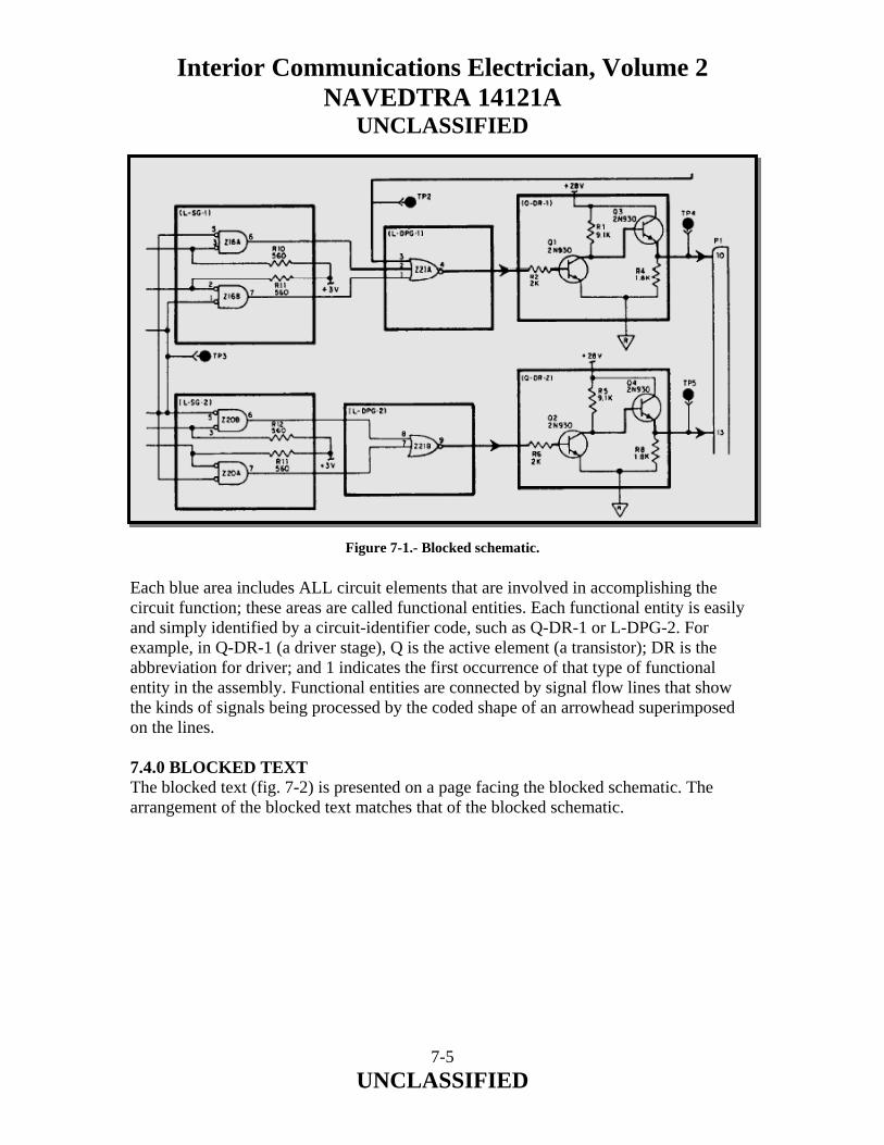
Interior Communications Electrician, Volume 2 NAVEDTRA 14121A
UNCLASSIFIED Figure 7-1.- Blocked schematic. Each blue area includes ALL circuit elements that are involved in accomplishing the circuit function; these areas are called functional entities. Each functional entity is easily and simply identified by a circuit-identifier code, such as Q-DR-1 or L-DPG-2. For example, in Q-DR-1 (a driver stage), Q is the active element (a transistor); DR is the abbreviation for driver; and 1 indicates the first occurrence of that type of functional entity in the assembly. Functional entities are connected by signal flow lines that show the kinds of signals being processed by the coded shape of an arrowhead superimposed on the lines. 7.4.0 BLOCKED TEXT The blocked text (fig. 7-2) is presented on a page facing the blocked schematic. The arrangement of the blocked text matches that of the blocked schematic.
7-5 UNCLASSIFIED
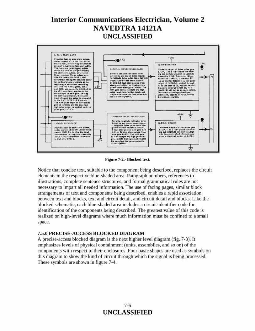
Interior Communications Electrician, Volume 2 NAVEDTRA 14121A
UNCLASSIFIED Figure 7-2.- Blocked text. Notice that concise text, suitable to the component being described, replaces the circuit elements in the respective blue-shaded area. Paragraph numbers, references to illustrations, complete sentence structures, and formal grammatical rules are not necessary to impart all needed information. The use of facing pages, similar block arrangements of text and components being described, enables a rapid association between text and blocks, text and circuit detail, and circuit detail and blocks. Like the blocked schematic, each blue-shaded area includes a circuit-identifier code for identification of the components being described. The greatest value of this code is realized on high-level diagrams where much information must be confined to a small space. 7.5.0 PRECISE-ACCESS BLOCKED DIAGRAM A precise-access blocked diagram is the next higher level diagram (fig. 7-3). It emphasizes levels of physical containment (units, assemblies, and so on) of the components with respect to their enclosures. Four basic shapes are used as symbols on this diagram to show the kind of circuit through which the signal is being processed. These symbols are shown in figure 7-4.
7-6 UNCLASSIFIED
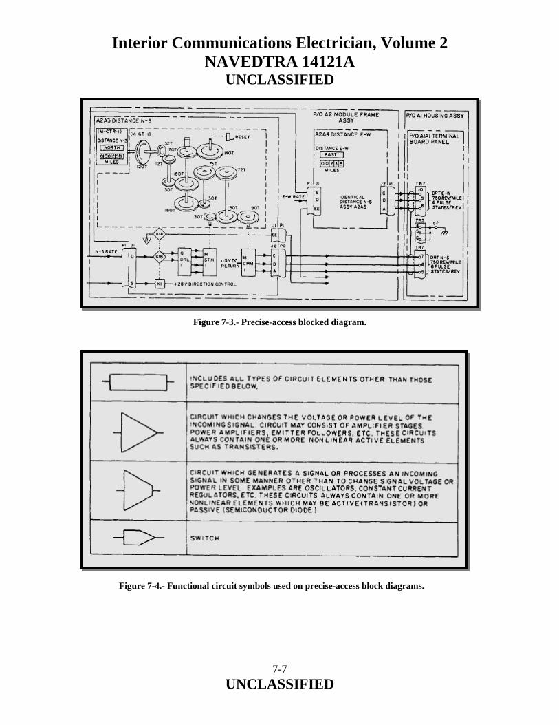
Interior Communications Electrician, Volume 2 NAVEDTRA 14121A
UNCLASSIFIED Figure 7-3.- Precise-access blocked diagram.
Figure 7-4.- Functional circuit symbols used on precise-access block diagrams.
7-7 UNCLASSIFIED
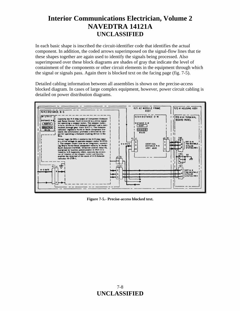
Interior Communications Electrician, Volume 2 NAVEDTRA 14121A
UNCLASSIFIED In each basic shape is inscribed the circuit-identifier code that identifies the actual component. In addition, the coded arrows superimposed on the signal-flow lines that tie these shapes together are again used to identify the signals being processed. Also superimposed over these block diagrams are shades of gray that indicate the level of containment of the components or other circuit elements in the equipment through which the signal or signals pass. Again there is blocked text on the facing page (fig. 7-5). Detailed cabling information between all assemblies is shown on the precise-access blocked diagram. In cases of large complex equipment, however, power circuit cabling is detailed on power distribution diagrams. Figure 7-5.- Precise-access blocked text.
7-8 UNCLASSIFIED

Interior Communications Electrician, Volume 2 NAVEDTRA 14121A
UNCLASSIFIED 7.6.0 OPERATING PROCEDURES Procedures that explain how to operate equipment under normal and emergency conditions are included in the operating procedures. Manuals for some equipment contain an operating chart that establishes a turn-on and checkout procedure. The chart displays chronologically all indications that can be recognized from outside the equipment. The indications are events, such as meter readings, lights, synchro rotating, or motor running noise that can be recognized by the human senses. Shaded bands stretching across the chart show the time lapse between events. All simultaneous events for a given step of the procedure appear on one horizontal line. Monitors are indicated in a solid black background box with white lettering. Front panel indicators and other recognizable indications with front panel markings, as applicable, and their associated cabinet nomenclature are located along the top of the chart, if an event fails to happen fault isolation is simplified by the indexing on the operator’s chart. This indexing will lead the troubleshooter to the proper maintenance dependency chart and the circuit chain upon which the missing event depends. The troubleshooter merely associates the operational step and the event that did not occur to find the pertinent circuit chain. A vertical column on the left side of the page contains the turn-on procedure in a sequence of steps consistent with the engineering designed plan of turn-on. Also in the left-hand column, boxed and indented, are checkout procedural steps that can be performed at any time during operation. These checkout steps will give an indication of the functional performance and will provide a sound basis for selection of operator, preventive-maintenance checks. 7.7.0 MAINTENANCE DEPENDENCY CHART One of the most important features of the SIMM is its troubleshooting tool, the maintenance dependency chart (MDC). In addition to front panel marked indicators displayed across the top of the page, it contains the various assemblies or circuit elements through which a signal passes, as well as their chassis or cabinet locations. Each horizontal line results in an action, such as a lamp lighting, a synchro rotating, a meter indicating, or an indication of signal availability. These actions are called events. Each horizontal line (event line) is a representation of the circuit that develops the event on its line. The MDC has the unique advantage of permitting the simple display of many events and their relationships in a limited space. The technique of isolating a fault is based upon a positive approach. It is an analysis of circuitry to verify whether the things that should have happened did happen. The event, if normal, is either readily observable or its signal can be measured. If either the action or signal is not present, components or circuits upon which the event is dependent can be readily ascertained.
7-9 UNCLASSIFIED
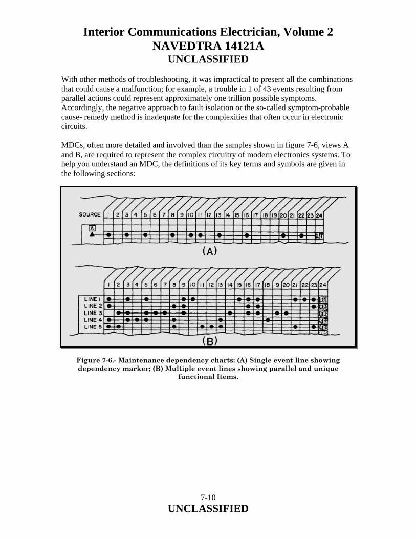
Interior Communications Electrician, Volume 2 NAVEDTRA 14121A
UNCLASSIFIED With other methods of troubleshooting, it was impractical to present all the combinations that could cause a malfunction; for example, a trouble in 1 of 43 events resulting from parallel actions could represent approximately one trillion possible symptoms. Accordingly, the negative approach to fault isolation or the so-called symptom-probable cause- remedy method is inadequate for the complexities that often occur in electronic circuits. MDCs, often more detailed and involved than the samples shown in figure 7-6, views A and B, are required to represent the complex circuitry of modern electronics systems. To help you understand an MDC, the definitions of its key terms and symbols are given in the following sections:
Figure 7-6.- Maintenance dependency charts: (A) Single event line showing dependency marker; (B) Multiple event lines showing parallel and unique
functional Items.
7-10 UNCLASSIFIED
Interior Communications Electrician, Volume 2 NAVEDTRA 14121A
UNCLASSIFIED EVENT–An action or an availability of a signal at a point in a circuit. The event may be characterized as motor running, temperature normal, lamps lit, lamps out, instruments indicating, signal or voltage available or not available, relay solenoids or thrusters energized, and so on. FUNCTIONAL ENTITY–A group of circuit elements that together form a basic functional circuit, such as a filter network, a voltage divider network, an amplifier stage, an oscillator stage, and a flip-flop stage. CIRCUIT ELEMENT–An individual piece or part for which no further breakdown can be made insofar as fault isolation is concerned. Relay or switch contacts, relay coils, resistors, capacitors, motors, and fuses are examples; printed-circuit boards are not. DEPENDENCY MARKER–The solid black triangle ( ) is used as a dependency marker. On an event line, it shows that an action or availability of a signal occurring on its line is dependent upon the occurrence of an action or availability of a signal directly above its apex. The signal or action above the dependency marker must be available and within specification for the event on the line of the dependency marker to result, if all the circuits and parts symbolically represented along the line are also performing properly. A solid black rectangle and white lettering represent a front panel indicator or an event recognizable from outside the cabinetry; an outlined rectangle with black lettering is a circuit point at which measurement might at some time be made. This circuit point may not be readily accessible. Internal test points that are readily accessible will be shown as gray-shaded rectangles. The dot (·) represents a circuit element or a functional entity. One aspect or state of circuit or component is represented by (·), and relay contacts are shown by (/·) or (·/), for continuity with relay energized or de-energized, respectively. 7.7.1 How to Use the Maintenance Dependency Chart Assume that in the illustration of a signal event line, figure 7-6, view A, dots (·) represent the basic circuits (oscillator stages, amplifier stages, and soon) or circuit elements (relay contacts, relay cards, and so on) that provide an action LIT at the end of a circuit chain (event line). The solid triangle ( ) is a dependency marker.
7-11 UNCLASSIFIED

Interior Communications Electrician, Volume 2 NAVEDTRA 14121A
UNCLASSIFIED The action LIT depends on the availability of a power source at the A block and on the proper operation of each of the circuits or circuit elements (·) represented along the event line. Now, if the lamp that indicates the action fails to light, any item along the event line, as well as the source, A, is a suspect item. Complex interrelated circuits often use some of the same circuits or circuit elements for more than one purpose. Thus, in multiple circuits, where many functional items are common to more than one circuit chain (event line), as shown in figure 7-6, view B, notice that actions (column 24) that occur at the end of these circuit chains are a result of certain common items employed in the parallel generation of the events shown on other circuit lines and some items that are unique to a single line. Look again at the multiple event line illustration (fig. 7-6, view B) for the purpose of analysis. If the lamp does not light on line 4 but does light on lines 1, 2, 3, and 5, it becomes apparent that the circuits or circuit elements represented by the dots in columns 4 and 18 are the only ones that can be suspected as faulty. All items represented by dots in other columns are proven good because of the proper occurrence of the action LIT on lines 1, 2, 3, and 5. For each major circuit, consistent with the precise-access blocked diagrams and blocked schematics, there is a corresponding MDC. Troubleshooting is accomplished by analyzing the charts. Faults must lie between the first bad event and the last good event. Acetate coverings for MDCs may be provided, or the charts maybe plasticized, so a grease or carbon pencil can be used for marking out areas that prove good. Marking out all known areas and actions that can be proven good rapidly reveals suspect areas. The use of a pencil to mark out all proven good items is recommended because technicians cannot normally remember all the areas or dependencies that they have proven good. 7.8.0 INDEXING OF RELATED INFORMATION Indexing is another important feature of the SIMM. The SIMM method of indexing (fig. 7-7) allows access to any bit of information relative to an assembly in a matter of seconds. The index is organized on the basis of major assemblies and then is broken down to the contained assemblies. Since each of the assemblies is full y treated within a four- or six-page data package, and the organization of details is always consistent, access to the desired kind of detail is almost immediate. The MDC is used to identify the functional entity or circuit element that is suspected, the assembly in which it is contained, and the cabinet containing the assembly. Accordingly, in using the index you need only find the cabinet nomenclature and look to the page number for the contained assembly data package.
7-12 UNCLASSIFIED
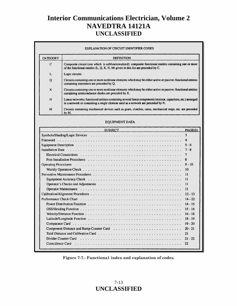
Interior Communications Electrician, Volume 2 NAVEDTRA 14121A
UNCLASSIFIED
Figure 7-7.- Functiona1 index and explanation of codes.
7-13 UNCLASSIFIED

Interior Communications Electrician, Volume 2 NAVEDTRA 14121A
UNCLASSIFIED 7.9.0 ALIGNMENT PROCEDURES Alignment procedures for each functional section of the set or system, as necessary, are included on as few pages as possible. The method of identifying alignment procedures is the same as for making other identifications from the MDC. The alignment procedures are directly keyed from the signal specifications listed on the MDC. If a particular event shown on the MDC is below specification and correctable by alignment, the step in the alignment chart is easy to find. Each part of the MDC treats a major functional segment of equipment. Likewise, the alignment actions are organized (charted) for each major fictional segment of the equipment. The identification system for the charts is used for the alignment procedure chart. For example, alignments that affect events on the MDC, part 2, will be found on the alignment chart, part 2, and so on. When required, alignment of subassemblies outside the set environment will be contained with the other details of individual assemblies in the data package for the assembly. 7.10.0 PARTS LOCATION AND IDENTIFICATION Equipment and assembly halftones and line drawings are overlaid with a blue-colored grid on which coordinates are placed to assist in parts location. Associated with the parts-location illustration is a cross-reference table identifying the items by reference designations, their coordinate positions, and significant military-type numbers or manufacture’ part numbers. 7.11.0 REPAIR OF MECHANICAL ASSEMBLY Mechanical assemblies, gear trains, and so on, are illustrated to the extent necessary to assure sufficient data for repair. When assemblies are illustrated in exploded form, index numbers are cross-referenced to contractors’ drawing numbers or to contractors’ vendors’ part numbers. Subassemblies, such as synchro motors, that frequently are identified by non-readily translatable military-type numbers also include sufficient meaningful data for ordering purposes. When complex assembly and disassembly procedures are involved but not obvious, detailed procedures are given. Exploded views on the same or facing pages will describe and illustrate these procedures. 7.12.0 IMPROVEMENTS Compared to the already described SIMM, newer editions of the manual will show improvements in method of presentation, use of MDC, and size. Instead of the blocked text, the improved manuals use a keyed text method of presentation in which the text material is arranged in tabular format and keyed to the diagram by circled numbers, as shown by figure 7-8.
7-14 UNCLASSIFIED

Interior Communications Electrician, Volume 2 NAVEDTRA 14121A
UNCLASSIFIED
Figure 7-8.- SIMM keyed text. This method permits significantly more text material to be presented than the blocked text method. Besides being used with the schematic diagrams, the keyed text is also used with the precise-access block diagrams (called functional block diagrams) and the overall block diagrams (called the function description diagrams). Instead of only one MDC for each major function, newer manuals will have additional MDCs for the functional block and schematic diagrams. The MDCs also will be provided with an acetate or Mylar overlay so troubleshooters can use grease pencils to mark their progress. The size of the new SIMM will be 11 by 27 inches, instead of 15 by 35 inches. This new size gives it a folded dimension of 9 by 11 inches, the same size as conventional manuals.
7-15 UNCLASSIFIED

Interior Communications Electrician, Volume 2 NAVEDTRA 14121A
UNCLASSIFIED 7.13.0 CHASSIS WIRING Chassis wiring is loosely defined as the wire or wires installed in an equipment cabinet that interconnect the assemblies of the cabinet. Chassis wiring varies in application and size of run. It may range from a harness or run of two wires, used in sound-powered amplifiers and telephone cases, to large cable runs, such as those in MC cabinets, dial telephone switchboards, and gyro binnacles. IC Electricians must be able to test, repair, and replace chassis wiring, regardless of its run size and application. 7.13.1 Testing Chassis Wiring In testing chassis wiring, it is not possible to substitute for good common sense. Your first step in testing chassis wiring of a faulty piece of equipment should always be a detailed visual inspection of the wiring harness, from terminal to terminal. A complete visual check will save you many hours of work looking for trouble that you could have detected in the first place by inspecting the equipment for visible damage. If certain wires are obviously at fault, you should replace them before going any further in the test. Your sense of smell can help in pinpointing burned or damaged wire that you may not see when making the visual inspection. Most burned electrical insulation will give off a noticeable, unpleasant odor that is readily detectable. The location of a burned wire, however, does not necessarily reveal the cause of the trouble. Signal tracing is the most reliable method of locating shorts, opens, or grounds in chassis wiring. The best method of making continuity tests for shorts and grounds in chassis wiring calls for the use of a multimeter and manufacturers’ instruction books. 7.13.2 Repairing Chassis Wiring A major consideration in repairing chassis wiring is the amount of time you have to complete the repair and get the equipment back in operation. If the equipment is to be “down” for a long time, be sure the repair is completed correctly. As a temporary repair, it is permissible to run a straight wire instead of following the original cable run. This temporary lead should be soldered in place, after you disconnect the faulty lead. This practice should only be done when there is insufficient time to make the proper repairs. When a few wires are to be replaced, lace them to the outside of the existing cable run. When many wires are to be replaced, remove the damaged wiring and re-run the new wires along the route of the old cable run. After connecting the wires, you should lace or clamp them in their original positions.
7-16 UNCLASSIFIED

Interior Communications Electrician, Volume 2 NAVEDTRA 14121A
UNCLASSIFIED You should avoid unnecessary slack in the cable runs and always try to keep your repairs neat and workmanlike. A properly replaced wire or cable run also will make it easier to trace later. 7.13.3 Replacing Chassis Wiring Sometimes your personnel may have to replace chassis wiring in components of IC systems, such as 21MC units. Chassis wiring is usually the last part to fail in electronic equipment, but it can wear out from minor friction and abrasion in the course of making other repairs, or it can be damaged by a malfunction that causes overheating or fire. Individual leads in chassis wiring must be replaced wire for wire. This is a tedious job, but one that requires only skill with a soldering iron. A wiring harness containing damaged wires is best repaired by replacing it with a prefabricated harness. Prefabricating a replacement harness is usually easier than repairing individual wires in the old harness. An installed harness is hard to work on, and soldering on it may damage other wiring insulation or electronic components. If the unit to be repaired is still in working order, the replacement harness can be made, and then installed whenever it is convenient to have the unit off the line. Tee first step in making a wiring harness is to make a wiring form or jig, as shown in figure 7-9. Build the form on a sheet of 1/4-inch plywood, using small (6d) finishing nails. Using a plastic ruler, measure the original harness and chassis in the unit to be repaired. Your measurements should let you outline the chassis and the location of the harness run and mark the positions of the terminals on the board. Drive nails at each terminal location and at points where the wires and harness bend. Write the terminal designations near the appropriate nails, using the wiring diagram from the equipment manual to double-check that terminal markings are correct. When this is done, you can return the unit to service until it is convenient to install the new harness. The wires are run between the terminal points, following the route outlined by the nails. Do not stretch the wires tight. The bitter ends of each wire are wrapped around the nails located at its terminal positions. When all terminals have been connected, the harness is formed and can be laced. If terminal connectors are to be used, they are soldered in place after lacing is complete, and spaghetti put in place. When the new harness is ready, you can install it in a relatively short time. If it is to replace a harness in equipment that is operating, the installation can be postponed until the ship is in port or the unit is not needed.
7-17 UNCLASSIFIED
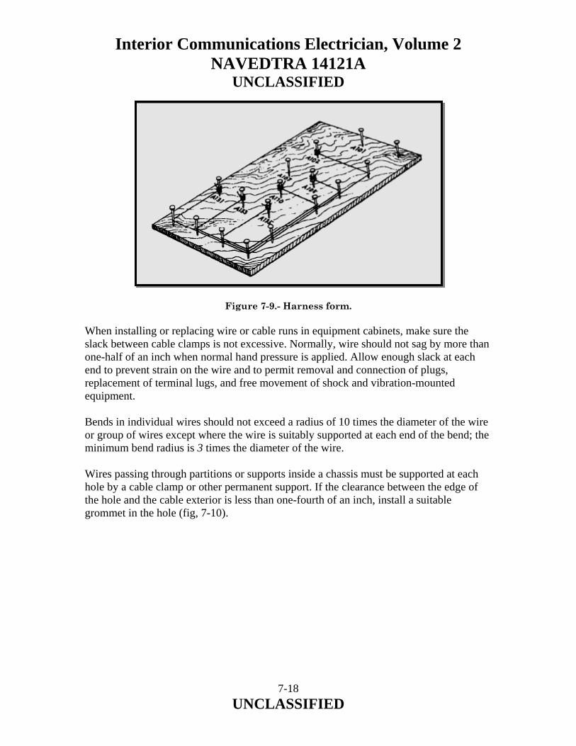
Interior Communications Electrician, Volume 2 NAVEDTRA 14121A
UNCLASSIFIED Figure 7-9.- Harness form. When installing or replacing wire or cable runs in equipment cabinets, make sure the slack between cable clamps is not excessive. Normally, wire should not sag by more than one-half of an inch when normal hand pressure is applied. Allow enough slack at each end to prevent strain on the wire and to permit removal and connection of plugs, replacement of terminal lugs, and free movement of shock and vibration-mounted equipment. Bends in individual wires should not exceed a radius of 10 times the diameter of the wire or group of wires except where the wire is suitably supported at each end of the bend; the minimum bend radius is 3 times the diameter of the wire. Wires passing through partitions or supports inside a chassis must be supported at each hole by a cable clamp or other permanent support. If the clearance between the edge of the hole and the cable exterior is less than one-fourth of an inch, install a suitable grommet in the hole (fig, 7-10).
7-18 UNCLASSIFIED
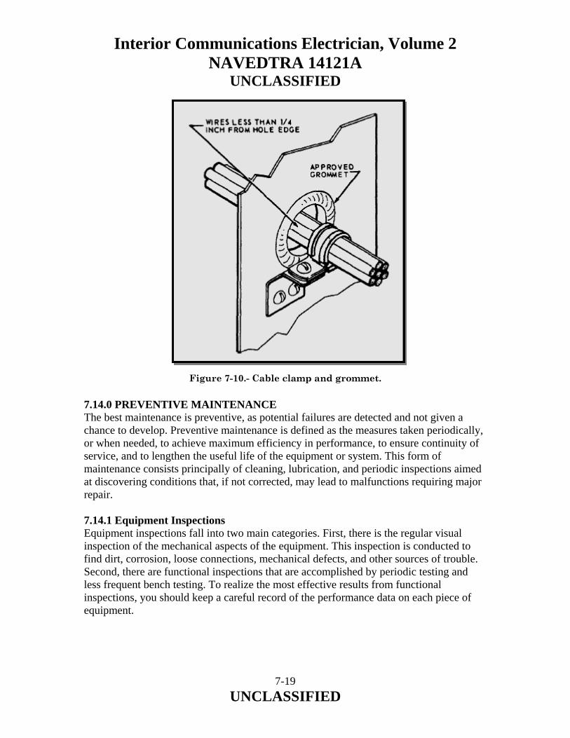
Interior Communications Electrician, Volume 2 NAVEDTRA 14121A
UNCLASSIFIED
Figure 7-10.- Cable clamp and grommet. 7.14.0 PREVENTIVE MAINTENANCE The best maintenance is preventive, as potential failures are detected and not given a chance to develop. Preventive maintenance is defined as the measures taken periodically, or when needed, to achieve maximum efficiency in performance, to ensure continuity of service, and to lengthen the useful life of the equipment or system. This form of maintenance consists principally of cleaning, lubrication, and periodic inspections aimed at discovering conditions that, if not corrected, may lead to malfunctions requiring major repair. 7.14.1 Equipment Inspections Equipment inspections fall into two main categories. First, there is the regular visual inspection of the mechanical aspects of the equipment. This inspection is conducted to find dirt, corrosion, loose connections, mechanical defects, and other sources of trouble. Second, there are functional inspections that are accomplished by periodic testing and less frequent bench testing. To realize the most effective results from functional inspections, you should keep a careful record of the performance data on each piece of equipment.
7-19 UNCLASSIFIED

Interior Communications Electrician, Volume 2 NAVEDTRA 14121A
UNCLASSIFIED 7.15.0 PERFORMANCE DATA RECORDS Locally prepared performance data records are valuable in several ways. By comparing data taken on a particular piece of equipment at different times, you can detect slow, progressive drifts that may not show in any one test. Though week-to-week changes may be slight, you should follow them carefully so necessary replacement or repair can be made before the lower limit of performance is reached. Any marked variation is abnormal, and it should be investigated immediately. Also, by keeping systematic records of performance and servicing data, maintenance personnel become acquainted with the equipment faster. Then too, the accumulated experience contained in the records furnishes a guide to swift and accurate troubleshooting. Most of the actual work of organizing and implementing a system of testing and servicing of equipment is outlined in the 3-M Systems. However, testing and records keeping can apply to maintenance-related functions not covered by the 3-M Systems. 7.16.0 CORRECTIVE MAINTENANCE Corrective maintenance consists of locating and correcting troubles in equipment or a system that fails to function properly. Location of troubles includes evaluation of equipment performance and troubleshooting. 7.16.1 Evaluating Performance The manufacturer’s instruction book for each particular piece of electrical/electronic equipment contains performance standards that enable the technician to make an intelligent evaluation of the operating capabilities and efficiency of the equipment. The standards are designed to make sure the equipment operates at maximum efficiency at all times; any reduction in performance indicates the need for corrective action. These instruction books also give the technician step-by-step performance checks, indicating clearly all the test connections and test equipment for each step. When a discrepancy is brought to your attention through an operator’s trouble call or as a result of an PMS check, you should first determine whether the equipment is faulty or not. It is a mistake to remove the equipment from operation before checking it thoroughly, unless you suspect a malfunction that could cause further damage to the equipment. IC Electricians should have a prescribed procedure to check a discrepancy or trouble call. You may find the following approach helpful in evaluating operating discrepancies.
• Visual in-place inspection–This inspection may disclose frayed or broken wiring and loose electrical or mechanical connections.
7-20 UNCLASSIFIED

Interior Communications Electrician, Volume 2 NAVEDTRA 14121A
UNCLASSIFIED
• Operational check–This check may pinpoint the trouble to a particular unit. In some cases, it may disclose the use of improper operating procedures, especially with new equipment by inexperienced personnel.
• Performance test–This testis an extension of the operational check and is
conducted with portable test equipment and built-in meters; it can help localize the source of the trouble.
IC Electricians should conduct a quality control inspection of all overhauled or repaired equipment before it is reinstalled. This inspection combines the visual inspection, operational check, and performance test to assure the equipment is in proper operating condition and ready for use. 7.16.2 Troubleshooting Corrective maintenance usually is concerned with the process of troubleshooting. There are several ways to describe troubleshooting. One description is as follows: several steps through which a technician gains information about a casualty, isolates and repairs the faulty component, and clearly understands the reason for the malfunction. When the presence of a malfunction has been recognized, the first phase of troubleshooting has begun. The operation of the system is analyzed to determine which area of the equipment is causing the trouble. When faulty operation of a piece of equipment has been traced to a particular stage or group of stages, the next phase of troubleshooting is begun-identifying, isolating, and repairing the faulty component or group of components. To prevent the reoccurrence of the malfunction, you must clearly understand the reason the malfunction occurred so all faulty components can be replaced; not just the most obvious ones. As a supervisor, you should make sure detailed trouble isolation procedures are performed according to the instruction manual for the equipment being repaired. 7.16.3 Testing Tubes Electron-tube failure accounts for most of the trouble in systems using tubes. It is impractical to try to locate faults by general tube checking. Only when the fault has been traced to a particular stage should tubes be tested. Then, only those tubes associated with the improperly functioning circuits should be tested.
7-21 UNCLASSIFIED
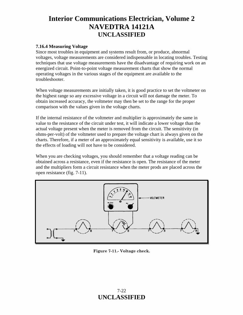
Interior Communications Electrician, Volume 2 NAVEDTRA 14121A
UNCLASSIFIED 7.16.4 Measuring Voltage Since most troubles in equipment and systems result from, or produce, abnormal voltages, voltage measurements are considered indispensable in locating troubles. Testing techniques that use voltage measurements have the disadvantage of requiring work on an energized circuit. Point-to-point voltage measurement charts that show the normal operating voltages in the various stages of the equipment are available to the troubleshooter. When voltage measurements are initially taken, it is good practice to set the voltmeter on the highest range so any excessive voltage in a circuit will not damage the meter. To obtain increased accuracy, the voltmeter may then be set to the range for the proper comparison with the values given in the voltage charts. If the internal resistance of the voltmeter and multiplier is approximately the same in value to the resistance of the circuit under test, it will indicate a lower voltage than the actual voltage present when the meter is removed from the circuit. The sensitivity (in ohms-per-volt) of the voltmeter used to prepare the voltage chart is always given on the charts. Therefore, if a meter of an approximately equal sensitivity is available, use it so the effects of loading will not have to be considered. When you are checking voltages, you should remember that a voltage reading can be obtained across a resistance, even if the resistance is open. The resistance of the meter and the multipliers form a circuit resistance when the meter prods are placed across the open resistance (fig. 7-11). Figure 7-11.- Voltage check.
7-22 UNCLASSIFIED

Interior Communications Electrician, Volume 2 NAVEDTRA 14121A
UNCLASSIFIED 7.16.5 Measuring Resistance Defective components can usually be located by measuring the dc resistance between various points in the circuit and a reference point or points (usually ground). This is true because a fault will generally produce a change in resistance values. Point-to-point resistance charts can be used advantageously when you make resistance measurements. The values given, unless otherwise stated, are measured between the indicated points and ground. Before making resistance measurements, the IC Electrician should make sure the power to the equipment under test has been turned off. Since an ohmmeter is essentially a low-range voltmeter and a battery, an ohmmeter connected to a circuit that already has voltages in it may be seriously harmed. The pointer may be deflected off-scale, and the meter movement maybe permanently damaged. Filter capacitors must be discharged with a shorting probe before making resistance measurements. This is extremely important when you are testing power supplies that are disconnected from their loads. If a capacitor discharges through the meter, the surge may burn out the meter movement. Furthermore, contact with a circuit containing a charged capacitor will endanger the life of the person making the test. 7.16.6 Comparing Waveforms The measurement and comparison of waveforms are considered to be very important parts of the circuit analysis used in troubleshooting. In some circuits (for example, pulse circuits), waveform analysis is indispensable. Waveforms may be observed at test points, shown in the waveform charts that are part of the maintenance literature for the equipment. You should note that the waveforms given in the instruction books are often idealized and do not show some of the details that are normally present when the actual waveform is displayed on an oscilloscope. By comparing the observed waveform with the reference waveform, faults can be localized rapidly. A departure from the normal waveform indicates a fault that is located between the point where the waveform is last seen to be normal and the point where it is observed to be abnormal. (For example, if a waveform is observed to be normal at the grid circuit and abnormal at the plate circuit of the same stage, this indicates that the trouble lies in that stage or possibly the input of the following stage.)
7-23 UNCLASSIFIED

Interior Communications Electrician, Volume 2 NAVEDTRA 14121A
UNCLASSIFIED If there is no trouble present in an equipment or system, a waveform observed at a point in the equipment should closely resemble the reference waveform given for that test point. The reference waveforms supplied with maintenance literature are the criteria of proper equipment performance. However, test equipment characteristics of usage can cause distortion of the observed waveform, though the equipment or system is operating normally. Several of the most common causes of these conditions are summarized in the following sections:
• The leads of the test oscilloscope may not be placed in the same manner as those preparing the reference waveforms, or the lead lengths may differ considerably. This is particularly significant in shielded test leads, where the capacitance per unit length is a factor.
• A type of test oscilloscope having different values of input impedance, different
sweep durations, or different frequency response may have been used.
• The equipment operating (and servicing) controls may not have settings identical to those used when the reference waveforms were prepared. This condition is normally to be expected when servicing adjustments are made in terms of their effect on the shape and amplitude of an observed waveform.
• The vertical or horizontal amplitudes of the reference and test patterns may not be
proportional. This will produce apparent differences between the waveforms when actually there is no difference.
Whether or not a minor waveform discrepancy may be disregarded depends upon the type of circuit being traced. A minor discrepancy is not regarded as significant unless the nature of the discrepancy indicates faulty operation of the equipment. In general, time should not be wasted in searching for faults when relatively minor differences are detected between the reference waveforms and those obtained by test.
7-24 UNCLASSIFIED

Interior Communications Electrician, Volume 2 NAVEDTRA 14121A
UNCLASSIFIED 7.17.0 AMPLIFIERS IN ANNOUNCING SYSTEMS In purchasing a public address system, where you already know its power requirements, locations and types of microphones, and number and types of speakers, you may have to decide between a system that uses vacuum-tube amplifiers or one that uses transistor amplifiers. Your decision should be based on factors other than relative costs. Here are some reasons for the use of transistor amplifiers instead of vacuum-tube amplifiers:
• The life of a transistor is longer than that of a vacuum tube.
• Transistors consume less power than vacuum tubes.
• Transistor amplifiers use dc power more efficiently than vacuum-tube amplifiers.
• Transistors operate more efficiently at low voltages than vacuum tubes.
• Microphonics signals generated by shock or vibrations are almost completely lacking in transistors.
• Power is instantly available at the throw of a switch.
• Ac hum is minimized.
On the other hand, vacuum-tube amplifiers offer these advantages over transistor amplifiers:
• Vacuum-tube replacements take less time than transistor replacements.
• Vacuum-tube amplifiers are less likely to be affected by high ambient temperatures or to suffer heat damage.
• Vacuum-tube amplifiers are easier to service on the bench.
7-25 UNCLASSIFIED
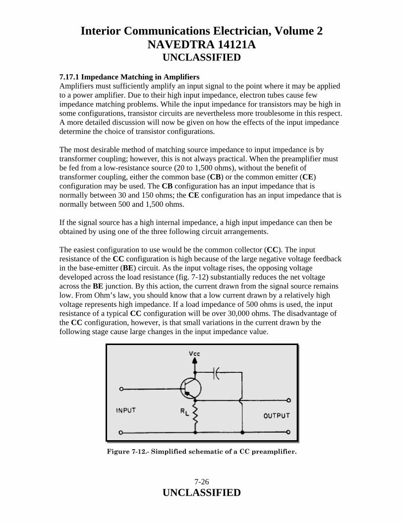
Interior Communications Electrician, Volume 2 NAVEDTRA 14121A
UNCLASSIFIED 7.17.1 Impedance Matching in Amplifiers Amplifiers must sufficiently amplify an input signal to the point where it may be applied to a power amplifier. Due to their high input impedance, electron tubes cause few impedance matching problems. While the input impedance for transistors may be high in some configurations, transistor circuits are nevertheless more troublesome in this respect. A more detailed discussion will now be given on how the effects of the input impedance determine the choice of transistor configurations. The most desirable method of matching source impedance to input impedance is by transformer coupling; however, this is not always practical. When the preamplifier must be fed from a low-resistance source (20 to 1,500 ohms), without the benefit of transformer coupling, either the common base (CB) or the common emitter (CE) configuration may be used. The CB configuration has an input impedance that is normally between 30 and 150 ohms; the CE configuration has an input impedance that is normally between 500 and 1,500 ohms. If the signal source has a high internal impedance, a high input impedance can then be obtained by using one of the three following circuit arrangements. The easiest configuration to use would be the common collector (CC). The input resistance of the CC configuration is high because of the large negative voltage feedback in the base-emitter (BE) circuit. As the input voltage rises, the opposing voltage developed across the load resistance (fig. 7-12) substantially reduces the net voltage across the BE junction. By this action, the current drawn from the signal source remains low. From Ohm’s law, you should know that a low current drawn by a relatively high voltage represents high impedance. If a load impedance of 500 ohms is used, the input resistance of a typical CC configuration will be over 30,000 ohms. The disadvantage of the CC configuration, however, is that small variations in the current drawn by the following stage cause large changes in the input impedance value. Figure 7-12.- Simplified schematic of a CC preamplifier.
7-26 UNCLASSIFIED
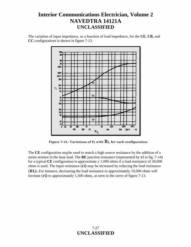
Interior Communications Electrician, Volume 2 NAVEDTRA 14121A
UNCLASSIFIED The variation of input impedance, as a function of load impedance, for the CE, CB, and CC configurations is shown in figure 7-13. Figure 7-13.- Variations of ri with RL for each configuration. The CE configuration maybe used to match a high source resistance by the addition of a series resistor in the base lead. The BE junction resistance (represented by ri in fig. 7-14) for a typical CE configuration is approximate y 1,000 ohms if a load resistance of 30,000 ohms is used. The input resistance (ri) may be increased by reducing the load resistance (RL). For instance, decreasing the load resistance to approximately 10,000 ohms will increase (ri) to approximately 1,500 ohms, as seen in the curve of figure 7-13.
7-27 UNCLASSIFIED
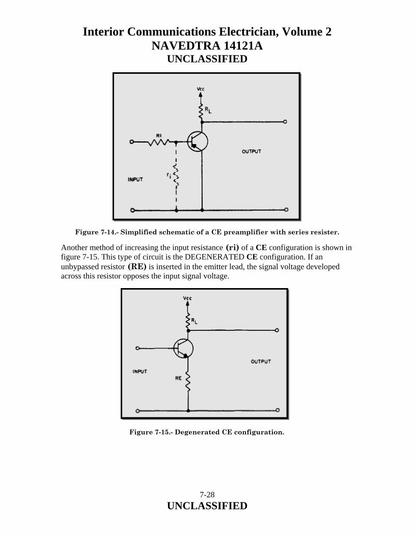
Interior Communications Electrician, Volume 2 NAVEDTRA 14121A
UNCLASSIFIED Figure 7-14.- Simplified schematic of a CE preamplifier with series resister. Another method of increasing the input resistance (ri) of a CE configuration is shown in figure 7-15. This type of circuit is the DEGENERATED CE configuration. If an unbypassed resistor (RE) is inserted in the emitter lead, the signal voltage developed across this resistor opposes the input signal voltage.
Figure 7-15.- Degenerated CE configuration.
7-28 UNCLASSIFIED
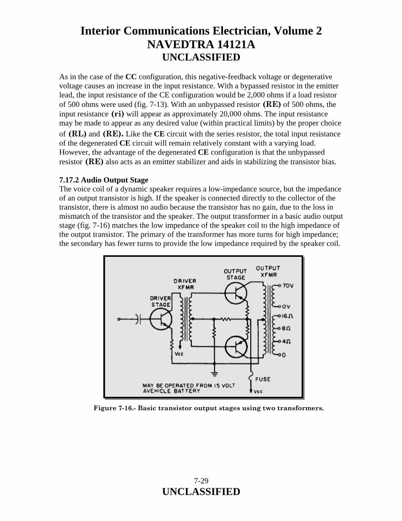
Interior Communications Electrician, Volume 2 NAVEDTRA 14121A
UNCLASSIFIED As in the case of the CC configuration, this negative-feedback voltage or degenerative voltage causes an increase in the input resistance. With a bypassed resistor in the emitter lead, the input resistance of the CE configuration would be 2,000 ohms if a load resistor of 500 ohms were used (fig. 7-13). With an unbypassed resistor (RE) of 500 ohms, the input resistance (ri) will appear as approximately 20,000 ohms. The input resistance may be made to appear as any desired value (within practical limits) by the proper choice of (RL) and (RE). Like the CE circuit with the series resistor, the total input resistance of the degenerated CE circuit will remain relatively constant with a varying load. However, the advantage of the degenerated CE configuration is that the unbypassed resistor (RE) also acts as an emitter stabilizer and aids in stabilizing the transistor bias. 7.17.2 Audio Output Stage The voice coil of a dynamic speaker requires a low-impedance source, but the impedance of an output transistor is high. If the speaker is connected directly to the collector of the transistor, there is almost no audio because the transistor has no gain, due to the loss in mismatch of the transistor and the speaker. The output transformer in a basic audio output stage (fig. 7-16) matches the low impedance of the speaker coil to the high impedance of the output transistor. The primary of the transformer has more turns for high impedance; the secondary has fewer turns to provide the low impedance required by the speaker coil. Figure 7-16.- Basic transistor output stages using two transformers.
7-29 UNCLASSIFIED

Interior Communications Electrician, Volume 2 NAVEDTRA 14121A
UNCLASSIFIED For a certain transistor, you can find the resistive value (impedance) that provides maximum gain with minimum distortion by consulting a transistor manual. Typical values range from approximately 2,000 to 5,000 ohms for one transistor, and they are doubled for push-pull outputs. Power to the secondary of a transformer is nearly equal to the power supplied by the primary due to the near unity coupling of the iron core in the transformer. The amount of power that an output transformer can handle is determined by the current and voltage ratings of its windings and by allowable losses. 7.17.3 Impedance Ratio Recall that the output voltage of a transformer varies directly with the turns ratio and that the output current varies inversely with the turns ratio. The proportions in equation form are: Multiply these proportions to get:
7-30 UNCLASSIFIED

Interior Communications Electrician, Volume 2 NAVEDTRA 14121A
UNCLASSIFIED The primary impedance (Z) of a matching transformer is the ratio of rated primary voltage to rated primary current. Similarly, the secondary impedance (Zs) is the ratio of rated secondary volts to rated secondary current. Substituting (Zp) for: you get the impedance ratio: Thus, the ratio of the two impedances that a transformer can match is equal to the turns ratio squared. Also, the turns ratio is equal to the square root of the impedance ratio. Example: Find the turns ratio for the transformer shown in figure 7-17. The plate resistance is 1,250 ohms and the primary impedance is twice as much to permit maximum undistorted power output. Solution:
7-31 UNCLASSIFIED

Interior Communications Electrician, Volume 2 NAVEDTRA 14121A
UNCLASSIFIED
Figure 7-17.- Output transformer used as an Impedance matching device. 7.17.4 Matching Speaker Loads Four equal impedances may be connected in a series-parallel arrangement to present the same impedance as one speaker to the amplifier (fig. 7-18, view A). In this case, the power delivered by the amplifier is divided equally among the four speakers. For better reliability, a series connection of two speakers in parallel is preferred. Should one speaker open up, the other three would continue to operate, but with a slight power change. However, in a parallel arrangement of two speakers in series (fig. 7-18, view A). If one speaker opens up, its other series member becomes inoperative and the system loses two speakers instead of one. There may be times when speakers of unequal impedances are coordinated into an impedance-matched system because they may be the only kind available. Such a combination might consist of an 8-ohm speaker and a 16-ohm speaker (fig. 7-18, view B). These two speakers in parallel result in an impedance of 5 1/3 ohms. The voltage drop across the two speakers is the same for both and the power division would be 2:1 in favor of the 8-ohm speaker. The alternate arrangement of series connection of the unequal-impedance speakers produces a branch impedance of 24 ohms with a power distribution that is 2:1 in favor of the 16-ohm speaker.
7-32 UNCLASSIFIED
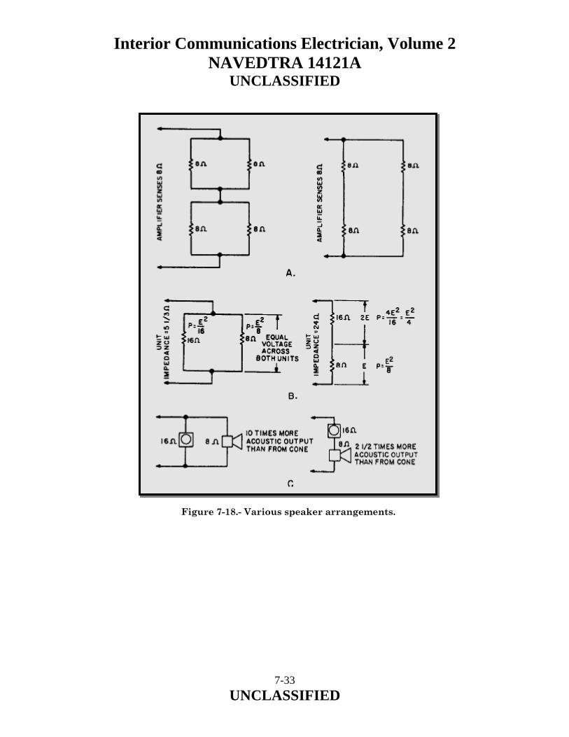
Interior Communications Electrician, Volume 2 NAVEDTRA 14121A
UNCLASSIFIED Figure 7-18.- Various speaker arrangements.
7-33 UNCLASSIFIED

Interior Communications Electrician, Volume 2 NAVEDTRA 14121A
UNCLASSIFIED The ratio of power conversion efficiencies of the 8-ohm speaker to the 16-ohm speaker is at least 5:1. Combining this output efficiency ratio with the actual power taken by the two units gives: For the parallel connection (fig. 7-18, view C). This shows that the 8-ohm speaker, taking twice as much electrical power as the 16-ohm speaker, is putting out 10 times as much acoustic power. The situation is not quite so upsetting in the series connection where the 8-ohm speaker accepts only one-half the power of the 16-ohm speaker. The power efficiency/power input ratio now becomes: Taking only one-half the input power of the 16-ohm speaker, the 8-ohm speaker is producing 2 1/2 times as much acoustic power. 7.17.5 Constant Voltage Systems With the constant-voltage distribution system, you can distribute audio power without having to match impedances or be too concerned about the effect of changes or additions on one part of the distribution system. Assuming that the line voltage from the amplifier is constant, you can make easy, on-the-spot level adjustments of an individual speaker to suit the needs of the particular area served by that speaker on the line. In addition, you conserve audio power.
7-34 UNCLASSIFIED
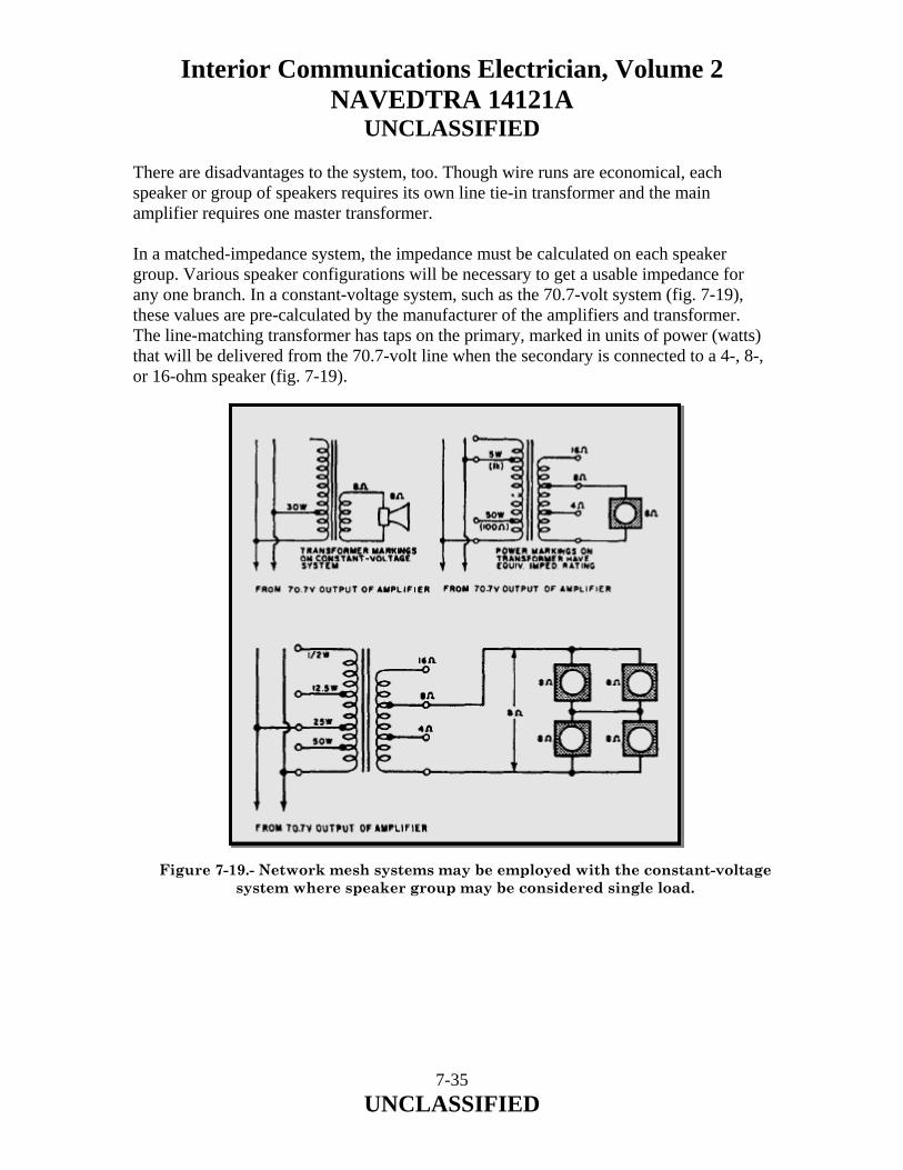
Interior Communications Electrician, Volume 2 NAVEDTRA 14121A
UNCLASSIFIED There are disadvantages to the system, too. Though wire runs are economical, each speaker or group of speakers requires its own line tie-in transformer and the main amplifier requires one master transformer. In a matched-impedance system, the impedance must be calculated on each speaker group. Various speaker configurations will be necessary to get a usable impedance for any one branch. In a constant-voltage system, such as the 70.7-volt system (fig. 7-19), these values are pre-calculated by the manufacturer of the amplifiers and transformer. The line-matching transformer has taps on the primary, marked in units of power (watts) that will be delivered from the 70.7-volt line when the secondary is connected to a 4-, 8-, or 16-ohm speaker (fig. 7-19). Figure 7-19.- Network mesh systems may be employed with the constant-voltage
system where speaker group may be considered single load.
7-35 UNCLASSIFIED

Interior Communications Electrician, Volume 2 NAVEDTRA 14121A
UNCLASSIFIED The pre-calculated values for the transformer will hold if the input voltage of the transformer is maintained at 70.7 volts. The amplifier gain control should be set at the point where the loaded amplifier delivers 70.7 volts RMS across the line at maximum load. Though you need not do the calculating for impedance, it is easy to do. By formula, power P across an impedance equals the square of the voltage divided by the impedance; that is: In a 70.7-volt system, power delivered is: Problem: You have a transformer whose 8-ohm secondary is connected to an 8-ohm speaker. What should be the impedance of the primary to deliver 50 watts to the speaker from a 70.7-volt line?
7-36 UNCLASSIFIED

Interior Communications Electrician, Volume 2 NAVEDTRA 14121A
UNCLASSIFIED Solution: If you wanted to draw 5 watts from the 70.7-volt line, the impedance of the transformer primary must be: The individual constant-voltage transformer at each speaker makes it possible to quickly adjust the power into the speaker for a given sound coverage. Also, where there is a mix of cone speakers and horn speakers, you can compensate quickly for the efficiency of the horn being greater than the cone’s (fig. 7-18, view C). Suppose you want to get as much power out of a horn as the cone is delivering, and the cone is tied to the 5-watt tap of its transformer. Tying the horn to the 1-watt tap of its transformer would take into account the 5:1 efficiency ratio. Now you can make the horn twice as loud as the cone by stepping up its tapped position to the 2-watt level. There is a limit to how many speakers you can tie across the line in this system, a limit that holds for the transformer-less matched system as well. The total load on the system by all the speaker transformers and the speakers should not exceed the total power capacity of the amplifier. In the transformer system, you find the limit by adding the rating capacities of the transformers. In the matched-impedance system, you must measure the voltage across voltages to power values, and then add them up.
7-37 UNCLASSIFIED

Interior Communications Electrician, Volume 2 NAVEDTRA 14121A
UNCLASSIFIED On a constant-voltage line, what do you do with a transformer that is marked in impedance with no mention of power? Using the formula, convert the primary impedance of the transformer to power. As an example, suppose the transformer has a primary marked 167 ohms and a secondary marked 8 ohms. How much power does this transformer take from the 70.7-volt line for its 8-ohm speaker load? Solution: 7.18.0 MODULAR UNITS The demand for small, maintainable circuitry in military equipment has led to many different construction techniques. One of the most popular is modular construction. Since modular assemblies incorporate several sub-miniaturized features not found in conventional equipment, some specialized knowledge and tools are required for efficient repair and maintenance.
7-38 UNCLASSIFIED

Interior Communications Electrician, Volume 2 NAVEDTRA 14121A
UNCLASSIFIED 7.19.0 MAINTENANCE CONCEPT A few definitions are helpful in understanding the terms involved. A module is, in the electronic sense, a packaged functional assembly of wired electronic components for use with other such assemblies. A modular assembly is constructed with standardized units or modules. Equipment that consists of replaceable assemblies (any type) is said to be of unitized construction. Modular construction is a type of unitized construction that consists of modular assemblies. For example, think of a carton of cigarettes. If each pack were a module, the carton would be an equipment of modular construction. Notice that the packs can be arranged differently without changing the outside dimensions of the carton. Although the cigarette packs are all the same size, the assemblies in many pieces of equipment are not. By their original concept, many modular assemblies were not to be maintained in the field. The intention was to replace a faulty assembly and ship it to a repair facility. As assemblies became more complex, the point was reached where the supply system required for the replacement was too costly. Many of the original modules were potted to discourage maintenance personnel from tampering with the insides. When the Navy reassessed this concept and called for shipboard maintenance of as much equipment as possible, most manufacturers began to make components accessible. However, it is difficult to dispel the conviction that modular assemblies are impossible to repair. This conviction may stem from a lack of experience in working with the printed circuits and the other components in modular assemblies. It is true that special tools and techniques are required. It is also true that satisfactory repairs can be made to any printed circuit by using a little care and common sense. With a little experience, repairs can be made as easily as in conventional assemblies, and often more easily because of improved accessibility. 7.20.0 REPAIR OF DEFECTIVE COMPONENTS One of the time-consuming steps of troubleshooting is the identification of specific components. In conventionally wired equipment, components are not always easy to locate. The circuitry in the chassis can become confusing since related components are often positioned in different areas of the chassis. In equipment that includes printed-circuit boards, identification of circuitry and components may be relatively simple. This type of circuit construction allows uniform placement of components. Just a quick, once-over glance of the circuitry is often all you need to see to place the overall layout of the chassis in your mind and to quickly focus your attention on the area of concern.
7-39 UNCLASSIFIED

Interior Communications Electrician, Volume 2 NAVEDTRA 14121A
UNCLASSIFIED Many commercial manufacturers have developed methods for quick identification. One of the most common is to impose a grid over a drawing of the board and a corresponding table that lists the part location. Another technique is to number points of interest on the schematic, and then provide a guide to locate the points on the board. Circuit tracing of the printed-circuit board maybe simpler than that of conventional wiring due to increased uniformity. If the circuit board is translucent, a 60-watt light bulb placed under the side being traced will simplify circuit tracing. However, be careful not to overheat delicate circuit components. In this way, you can locate test points without viewing both sides of the board. Resistance or continuity measurements can be made from the component side of the board. In some cases, a magnifying glass will help in locating very small breaks in the wiring. Voltage measurements can be made on either side of the board. However, a needlepoint probe is needed to penetrate the protective coating on the wiring. You also can locate hairline cracks by making continuity checks. As a supervisor, you should make sure the people in your shop or maintenance crews observe the following precautions:
• Observe power supply polarities when measuring the resistance of the circuits containing transistors or other semiconductors. Such parts are polarity and voltage sensitive. Reversing the plate voltage polarity of a triode vacuum tube will keep the stage from operating, but generally will not injure the tube. Reversing the voltage applied to a transistor or other semiconductor will ruin it very quickly.
CAUTION: Ohmmeter voltage for checking transistors and their circuits should be 3 volts or less.
• Make certain power line leakage current is not excessive before applying ac power-operated test equipment or soldering irons. Use an isolation transformer with all test equipment and soldering irons operated on ac power, unless the equipment contains a transformer in its power supply or shows no leakage current. With all test equipment (whether transformer operated or not), connect a ground lead from the ground of the circuit to be tested to the test equipment ground.
7-40 UNCLASSIFIED

Interior Communications Electrician, Volume 2 NAVEDTRA 14121A
UNCLASSIFIED
• Apply a signal from test equipment by starting with a low output signal setting, then proceeding to the required signal level. Be sure the signal applied is below the rating given for the circuit under test.
• Make sure all parts in a circuit are secure before starting to test the circuit or
turning on the equipment power. Do not cause an inductive kickback or transient current by moving loose connections, disconnecting parts, inserting or removing transistors or similar components, or changing modular units while the equipment power is on or under test.
• Remove all capacitance charges from parts and test equipment before attaching
them to a modular assembly. 7.21.0 SUBSTITUTION OF PARTS If a specified part cannot be obtained a suitable substitute part may be used temporarily, provided the substitute is replaced with the specified part as soon as it can be obtained. Make sure the failed part is the source of trouble and not the symptom of another failure. 7.22.1 Resistors and Capacitors The use of two or more resistors or capacitors in either series or parallel combinations to replace a burned-out component is a common practice. When the proper size resistor or capacitor is not available, check your spare parts drawer to see if you can use what you have on hand in a series or parallel combination. 7.22.2 Tubes and Transistors Substitution for defective tubes or transistors is usually an easy task. By consulting the proper substitution manual, and using the specifications for the tube or transistor you wish to replace, you can normally locate an acceptable substitute. Be certain to match the minimum specifications for the tube or transistor that you are trying to replace. 7.22.3 Relays and Switches When replacing a relay, switch, or similar control device, be sure to consult the proper instruction book or blueprint to check the voltage and current ratings before you start looking for a substitute. When replacing a relay, also consider the resistance of the coil and the type and arrangement of the contacts. It may also be possible to make the replacement part yourself or do something else that will reduce downtime. Remember, you are only looking for a temporary replacement.
7-41 UNCLASSIFIED

Interior Communications Electrician, Volume 2 NAVEDTRA 14121A
UNCLASSIFIED 7.22.0 SWITCHBOARD MAINTENANCE Another duty of an IC Electrician is the maintenance of the power distribution systems assigned to your division. Normally, the required inspections and cleanings are outlined on maintenance requirement cards (MRCs). When the inspection and cleaning is due, you often think only of the main IC switchboard. The small local IC switchboards located in the engineering spaces and remote sections of the ship are forgotten. Auxiliary IC panels may have their own MRCs. You, as a supervisor, should make sure all power panels receive the attention needed. 7.22.1 Inspection and Cleaning At least once a year and during overhaul, each switchboard propulsion control cubicle, distribution panel, and motor controller should be de-energized and tagged out for a complete inspection and cleaning of all bus equipment. Inspection of the de-energized equipment should not be limited to visual examination but should include grasping and shaking electrical connections and mechanical parts to be certain that all connections are tight and that mechanical parts are free to function. Be certain no loose tools or articles are left in or around switchboards or distribution panels. Check the supports of bus work to be certain the supports will prevent contact between bus bars of opposite polarity or contact between bus bars and grounded parts during periods of mechanical shock. Clean the bus work and the creepage surfaces of insulating material; be certain creepage distances (across which leakage currents can flow) are ample to prevent arcing. Bus bars and insulating materials can be cleaned with dry wiping clothes and a vacuum cleaner. Make sure the switchboard or distribution panel is completely de-energized and will remain so until the work is completed; avoid cleaning live parts because of the danger to personnel and equipment. The insulated front panels of switchboards can be cleaned without de-energizing the switchboard. These panels can usually be cleaned by wiping with a dry cloth. However, a damp, soapy cloth can be used to remove grease and fingerprints. Then wipe the surface with a cloth dampened in clear water to remove all soap and dry with a clean, dry cloth. Cleaning cloths must be rung out thoroughly so no water runs down the panel. Clean a small section at a time and then wipe dry.
7-42 UNCLASSIFIED

Interior Communications Electrician, Volume 2 NAVEDTRA 14121A
UNCLASSIFIED 7.22.2 Rheostats and Resistors Be certain the ventilation of rheostats and resistors is not obstructed. Replace broken or burned-out resistors. Temporary repairs of rheostats can be made by bridging burned-out sections when replacements are not available. Apply a light coat of petrolatum to the faceplate contacts of rheostats to reduce friction and wear. Be certain no petrolatum is left in the spaces between the contact buttons, as this may cause burning or arcing. Check all electrical connections for tightness and wiring for frayed or broken leads. 7.22.3 Instruments The pointer of each switchboard instrument should read zero when the instrument is disconnected from the circuit. The pointer may be brought to zero by external screwdriver adjustment. CAUTION: This should not be done unless proper authorization is given. Repairs to the switchboard instruments should be made only by the manufacturers, shore-repair activities, or tenders. 7.22.4 Fuses Be certain fuses are the right size; clips make firm contact with the times; lock-in devices (if provided) are properly fitted; and all connections in the wiring to the fuses are tight. 7.22.5 Control Circuits Control circuits should be checked to ensure circuit continuity and proper relay and contactor operation. Because of the numerous types of control circuits installed in naval ships, it is impractical to set up any definite operating test procedures in this training manual. In general, certain control circuits, such as those for starting motors or motor-generator sets, or voltmeter switching circuits are best tested by using the circuits as they are intended to operate under service conditions. Protective circuits, such as overcurrent, reverse power, or reverse current circuits, usually cannot be tested by actual operation because of the danger involved to the equipment. These circuits should be visually checked and, when possible, relays should be operated manually to be certain the rest of the protective circuit performs its intended functions. Exercise extreme care not to disrupt vital power service or damage electrical equipment. Normally these checks and inspections are outlined on MRCs.
7-43 UNCLASSIFIED

Interior Communications Electrician, Volume 2 NAVEDTRA 14121A
UNCLASSIFIED 7.22.6 Bus Transfer Equipment Bus transfer equipment should be tested weekly. For manual bus transfer equipment, manually transfer a load from one power source to another and check the mechanical operation and mechanical interlocks. For automatic bus transfer equipment, check the operation with the control switches. The test should include operation initiated by cutting off power (opening a normal feeder circuit breaker) to ascertain if an automatic transfer occurs. These tests and inspections are normally outlined on MRCs. 7.23.0 DIAGNOSTIC MAINTENANCE When you must perform electrical repair on energized switchboards, first be sure to obtain the approval of the commanding officer. Personnel with telephone headsets should be stationed by circuit breakers to de-energize the switchboard immediately and call for help in case of emergency. The person doing the work should wear rubber gloves and should not wear loose clothing or metal articles. 7.23.1 Current Transformers The secondary of a current transformer should never be open while the primary is carrying current. Failure to observe this precaution results in possible damage to the transformer and the generation of a secondary voltage that may be sufficient magnitude to injure personnel or damage insulation. A current transformer energized with an open-circuited secondary will overheat due to magnetic saturation of the core. Even though the overheating may have been insufficient to produce permanent damage, the transformer should be carefully demagnetized and recalibrated to ensure accurate measurements. The secondary should always be short-circuited when it is not connected to a current coil. 7.23.2 Potential Transformers The secondary of a potential transformer should never be short-circuited. The secondary circuit should be completed only through a high resistance, such as a voltmeter or a potential coil circuit, or should be open when the primary is energized. A short-circuited secondary allows excessive current to flow, which may damage the transformer. 7.24.0 IC GYRO WATCHSTANDING As an IC1 or ICC, you will be required to set up and train an IC gyro room watch. This training should be tailored to the needs of your command with the commanding officer’s authorization. This training should be documented and conducted according to the requirements of the Standard Organization and Regulations of the U.S. Navy, OPNAVINST 3120.32C.
7-44 UNCLASSIFIED

Interior Communications Electrician, Volume 2 NAVEDTRA 14121A
UNCLASSIFIED
7-45 UNCLASSIFIED
7.25.0 SUMMARY In this chapter, we have described the different uses of schematics and drawings by IC Electricians when performing maintenance, described the principles of testing, repairing, and replacing chassis wiring. We have identified the characteristics of amplifiers used in announcing systems, and discuss the principles of impedance matching and identified some of the fundamentals of modular assemblies and parts substitution in maintenance work.
Interior Communications Electrician, Volume 2 NAVEDTRA 14121A
UNCLASSIFIED
APPENDIX-A GLOSSARY ALARM ACKNOWLEDGE– Push button that must be depressed to silence an alarm horn. ALARM LOG– Record of quantities that are in an alarm condition only. ALIGNED SECTION– A section view in which some internal features are revolved into or out of the plane of the view. ANALOG DATA– Data represented in continuous form, as contrasted with digital data having discrete values. AND GATE– (1) An electronic gate whose output is energized only when every input is in its prescribed state. An AND gate performs the function of the logical “AND”; also called an AND circuit. (2) A binary circuit, with two or more inputs and a single output, in which the output is a logic 1 only when all inputs are a logic 1 and the output is a logic 0 when any one of the inputs is a logic 0. ANNUNCIATOR– A device that gives an audible and a visual indication of an alarm condition. APPLICATION BLOCK– A part of a drawing of a subassembly showing the reference number for the drawing of the assembly or adjacent subassembly. ARCHITECT’S SCALE– Scale used when dimensions or measurements are to be expressed in feet and inches. ASSEMBLY– A number of parts or subassemblies, or any combination thereof, joined together to perform a specific function. AUXILIARY VIEW– An additional plane of an object, drawn as if viewed from a different location. It is used to show features not visible in the normal projections. AXONOMETRIC PROJECTION– A set of three or more views in which the object appears to be rotated at an angle, so that more than one side is seen.
A-1 UNCLASSIFIED
Interior Communications Electrician, Volume 2 NAVEDTRA 14121A
UNCLASSIFIED
BELL LOG– A printed record of changes in the ship’s operative conditions, such as speed or point of control. BILL OF MATERIAL– A list of standard parts or raw materials needed to fabricate an item. BINARY UNIT– One of the two possible alternatives, such as 1 or 0, YES or NO, ON or OFF. BLOCK DIAGRAM– Drawing of a system using blocks for components to show the relationship of components. BLUEPRINTS– Copies of mechanical or other types of technical drawings. Although blueprints used to be blue, modem reproduction techniques now permit printing of black on white as well as colors. BODY PLAN– An end view of a ship’s hull, composed of superimposed frame lines. BREAK LINES– Lines to reduce graphic size of an object, generally to conserve paper space. CALIBRATION ACTIONS– The number of calibrations performed by the related calibration activity (laboratory) during the reporting period. CARD– See PRINTED CIRCUIT BOARD. CASUALTY– An event or series of events in progress during which equipment damage and/or personnel injury has already occurred. The nature and speed of these events are such that proper and correct procedural steps will only serve to limit equipment damage and/or personnel injury. CENTER LINES– Lines that indicate the center of a circle, arc, or any symmetrical object; consist of alternate long and short dashes evenly spaced. CLOCK– An instrument for measuring and indicating time, such as a synchronous pulse generator. COMPONENT PARTS– Individual units of a subassembly. COMPONENTS– Any electrical device, such as a coil, resistor, transistor, and so forth.
A-2 UNCLASSIFIED

Interior Communications Electrician, Volume 2 NAVEDTRA 14121A
UNCLASSIFIED
COMPUTER– A data processor that can perform substantial computation, including numerous arithmetic or logic operations, without the intervention by a human operator during the run. COMPUTER LOGIC– The electrical processes used by a computer to perform calculations and other functions. CONDITION– State of being of a device, such as ONOFF, GO-NO GO, and SO forth. CONTINUOUS DISPLAY– Electrical instrument giving a continuous indication of a measured quantity. CONTROL MODE– Method of system control at a given time. CONTROL POWER– Power used to control or operate a component. CONTROL TRANSMITTER (CX)– A type of synchro that converts a mechanical input, which is the angular position of its rotor, into an electrical output signal. The output is taken from the stator windings and is used to drive either a CDX or CT. CONTROL TRANSFORMER (CT)– A type of synchro that compares two signals: the electrical signal applied to its stator and the mechanical signal applied to its rotor. The output is an electrical voltage, which is taken from the rotor winding and is used to control a power-amplifying device. The phase and amplitude of the output voltage depends on the angular position of the rotor with respect to the magnetic field of the stator. CONTROL SIGNAL– Signal applied to a device that makes corrective changes in a controlled process. CONTROL DIFFERENTIAL TRANSMITTER (CDX)– A type of synchro that transmits angular information equal to the algebraic sum or difference of the electrical input supplied to its stator, and the mechanical input supplied to its rotor. The output is an electrical voltage taken from the rotor windings. CONVERTER– A device for changing one type of signal to another; for example, alternating current to direct current. CORRECTIVE MAINTENANCE– Includes location and repair of equipment failures.
A-3 UNCLASSIFIED

Interior Communications Electrician, Volume 2 NAVEDTRA 14121A
UNCLASSIFIED
CORRESPONDENCE– The term given to the positions of the rotors of a synchro receiver when both rotors are on 0 degree or displaced from 0 degree by the same angle. DAMPING– (1) The process of smoothing out oscillations. (2) In a meter, this process is used to keep the pointer of the meter from overshooting the correct reading. (3) A mechanical or electrical technique used in synchro receivers to prevent the rotor from oscillating or spinning. Damping is also used in servo systems to minimize overshoot of the load. DATA TRANSMISSION– The transfer of information from one place to another or from one part of a system to another. DEAD BAND– The range of values over which a measured variable can change without affecting the output of an amplifier or automatic control system. DEMAND– To request a log printout or data display. DEMODULATOR– A circuit used in servo systems to convert an ac signal to a dc signal. The magnitude of the dc output is determined by the magnitude of the ac input signal, and its polarity is determined by whether the ac input signal is in or out of phase with the ac reference voltage. DIGITAL– Pertaining to data in the form of digits. DIGITAL CLOCK– A device for displaying time in digits. DIRECT CURRENT– An electric current that flows in one direction only. DRAWING NUMBER– An identifying number assigned to a drawing or a series of drawings. DRAWING– The original graphic design from which a blueprint may be made; also called plans. DRIFT– A slow change in some characteristics of a device, such as frequency, current, and direction. ELECTRICAL ZERO– A standard synchro position, with a definite set of stator voltages, that is used as the reference point for alignment of all synchro units.
A-4 UNCLASSIFIED

Interior Communications Electrician, Volume 2 NAVEDTRA 14121A
UNCLASSIFIED
ELECTRICAL-LOCK– A synchro zeroing method. This method is used only when the rotors of the synchros to be zeroed are free to turn and their leads are accessible. ELECTROMECHANICAL DRAWING– A special type of drawing combining electrical symbols and mechanical drawing to show the composition of equipment that combines electrical and mechanical features. ELEMENTARY WIRING DIAGRAM– (1) A shipboard wiring diagram showing how each individual conductor is connected within the various connection boxes of an electrical circuit or system. (2) A schematic diagram; the term is sometimes used interchangeably with schematic diagram, especially a simplified schematic diagram. EMERGENCY– An event or series of events in progress that will cause damage to equipment unless immediate, timely, and correct procedural steps are taken. ERROR DETECTOR– The component in a servo system that determines when the load has deviated from its ordered position, velocity, and so on. ERROR SIGNAL– (1) In servo systems, the signal whose amplitude and polarity or phase are used to correct the alignment between the controlling and the controlled elements. (2) The name given to the electrical output of a control transformer. EXCITATION VOLTAGE– The supply voltage required to activate a circuit. FAIL– Loss of control signal or power to a component. Also breakage or breakdown of a component or component part. FAIL POSITION– Operating or physical position to which a device will go upon loss of its control signal. FEEDBACK– A value derived from a controlled function and returned to the controlling function. FINISH MARKS– Marks used to indicate the degree of smoothness of the finish to be achieved on surfaces to be machined. FORMAT– The general makeup or style of a drawing. FREQUENCY– (1) The number of complete cycles per second existing in any form of wave motion, such as the numbers of cycles per second of an alternating current. (2) The rate at which the vector that generates a sine wave rotates.
A-5 UNCLASSIFIED

Interior Communications Electrician, Volume 2 NAVEDTRA 14121A
UNCLASSIFIED
FUNCTION– To perform the normal or characteristic action of something, or a special duty or performance required of a person or thing in the course of work. GATE– As applied to logic circuitry, one of several types of electronic devices that will provide a particular output when specified input conditions are satisfied. Also, a circuit in which a signal switches another signal on or off. GENERATOR– A machine that converts mechanical energy to electrical energy by applying the principle of magnetic induction. A machine that produces ac or dc voltage, depending on the original design. GYRO– Abbreviation for gyroscope. GYROSCOPE– A mechanical device containing a spinning mass mounted so it can assume any position in space. HERTZ– A unit of frequency equal to one cycle per second. HYDRAULIC ACTUATOR– A device that converts hydraulic pressure to mechanical movement. INACTIVE CODE– An asterisk (*) preceding the customer/laboratory code indicating that the activity is inactive (not currently accepted by MEASURE), and no updating occurs. (formats 100 & 105) INTERCONNECTION DIAGRAM– Diagrams that show the cabling between electronic units, as well as how the terminals are connected. INTERLOCK– A device that prevents an action from taking place at the desired time, but that allows the action when all required conditions are met. ISOMETRIC DRAWING– A type of pictorial drawing. See isometric wiring diagram. ISOMETRIC WIRING DIAGRAM– A diagram showing the outline of a ship, an aircraft, or other structure, and the location of equipment, such as panels and connection boxes and cable runs. JACKING GEAR– An electric motor-driven device that rotates the turbine shaft, reduction gears, and line shaft at a low speed. LEADER LINES– Thin, unbroken lines used to connect numbers, references, or notes to appropriate surfaces or lines.
A-6 UNCLASSIFIED

Interior Communications Electrician, Volume 2 NAVEDTRA 14121A
UNCLASSIFIED
LEGEND– A description of any special or unusual marks, symbols, or line connections used in the drawing. LINEAR– Straight line relationship where changes in one function are directly proportional to changes in another function. LOGIC– The basic principles and applications of truth tables, interconnections of off-on circuit elements, and other factors involved in mathematical computation in automatic data processing systems and other devices. LOGIC DIAGRAMS– In computers and data processing equipment, a diagram representing the logical elements and their interconnections without necessarily expressing construction or engineering details. LOGIC INSTRUCTION– Any instruction that executes a logic operation that is defined in symbolic logic, such as AND, OR, NAND, or NOR. MAINTENANCE– Work done to correct, reduce, or counteract wear, failure, and damage to equipment. MANUAL THROTTLE CLUTCH– Means of mechanically disconnecting the throttle hand wheels, mounted on the engine-room console, from the reach rods that are connected to the throttle valves. MECHANICAL DRAWING– See drawings. Applies to scale drawings or mechanical objects. METRL CYCLE– The number of months established as the optimum period of time the corresponding equipment can be used before recalibration is required. MFR– A five-character alpha/numeric or three character alphabetical code representing the specific manufacturer for the corresponding equipment model number. MIL-STD– Military standards. A formalized set of standards for supplies, equipment, and design work purchased by the United States Armed Forces. MODIFICATION MAN-HOURS– The total man-hours expended on modifications by the related calibration activity (laboratory) during the reporting period. MODIFICATION ACTIONS– The number of modifications performed by the related calibration activity (laboratory) during the reporting period.
A-7 UNCLASSIFIED

Interior Communications Electrician, Volume 2 NAVEDTRA 14121A
UNCLASSIFIED
MODULE– Subassemblies mounted in a section. MONITOR– One of the principal operating modes of a data logger that provides a constant check of plant conditions. MONITORING POINT– The physical location at which any indicating device displays the value of a parameter at some control station. NO-BREAK POWER SUPPLY– A device that supplies temporary power to the console during failure of the normal power supply. NORMAL MODE– Operating condition at normal ahead speeds, differing from maneuvering, where certain functions, pumps, or valves are not required, while others are for proper operation of ship and machinery. NOTES– Descriptive writing on a drawing to give verbal instructions or additional information. NULL POSITION— Condition where the output shaft is positioned to correspond to that which the input shaft has been set. OBLIQUE DRAWING– A type of pictorial drawing in which one view is an orthographic projection and the views of the sides have receding lines at an angle. ONE-LINE SCHEMATIC– A drawing of a system using only one line to show the tie-in of various components; for example, the three conductors needed to transmit 3-phase power are represented by a single line. ONE-LINE SKETCH– A drawing using one line to outline the general relationship of various components to each other. OPEN LOOP– System having no feedback. OPERATING CHARACTERISTICS– Combination of a parameter and its set point. OR GATE– A gate that performs the logic OR function. It produces an output 1 whenever any or all of its inputs is/are 1. PARAMETER– A variable, such as temperature, pressure, flow rate, voltage, current, or frequency that may be indicated, monitored, checked, or sensed in any way during operation or testing.
A-8 UNCLASSIFIED
Interior Communications Electrician, Volume 2 NAVEDTRA 14121A
UNCLASSIFIED
PERIPHERAL– Existing on or new the boundary of a surface or area. PICTORIAL DRAWING– A drawing that gives the real appearance of an object, showing the general location, function, and appearance of parts and assemblies. PILOT MOTOR– A small dc motor that drives the input shaft of an actuator. PLAN VIEW– A view of an object or area as it would appear from directly above. POWER SUPPLY– A module that converts the 115-volt 60-hertz incoming power to ac or dc power at a more suitable voltage level. PRINTED CIRCUIT BOARD– Devices usually plugged into receptacles that are mounted in modules. PRIORITY– Order established by relative importance of the function. PROTECTIVE FEATURE– Feature of a component or component part designed to protect a component or system from damage. RECEIVER– (1) The object that responds to the wave or disturbance. Same as DETECTOR. (2) Equipment that converts electromagnetic energy into a visible or an audible form. (3) In radar, a unit that converts rf echoes to video and/or audio signals. REFERENCE NUMBERS– Numbers used on one drawing to refer the reader to another drawing for more detail or other information. REFERENCE POINT– A point in a circuit to which all other points in the circuit are compared. REFERENCE SIGNAL– Command signal that requests a specific final condition. RELAY– An electromagnetic device with one or more sets of contacts that change position by the magnetic attraction of a coil to an armature. REVISION BLOCK– Located in the upper right corner of a print. Provides a space to record any changes made to the original print. ROTOR– The rotating member of a synchro that consists of one or more coils of wire wound on a laminated core. Depending on the type of synchro, the rotor functions similar to the primary or secondary winding of a transformer.
A-9 UNCLASSIFIED

Interior Communications Electrician, Volume 2 NAVEDTRA 14121A
UNCLASSIFIED
SCALE– The ratio between the measurement used on a drawing and the measurement of the object it represents. A measuring device, such as a ruler, having special gradations. SCALING– Applying a factor of proportionality to data or signal levels. SCAT CODE– The subcategory (SCAT) code assigned to the equipment, if applicable. SCHEMATIC DIAGRAM– A diagram using graphic symbols to show how a circuit functions electrically. SEB NUMBER– The number of the support equipment change that contains the modification implemented on the corresponding equipment by the related calibration activity (laboratory). SELSYN– Self-synchronizing device or synchromotor. SENSING POINT– Physical and/or functional point in a system at which a signal may be detected or monitored in an automatic operation. SENSOR– A device that is sensitive to temperature, pressure, position, level, or speed. SERVICING LABEL (SL)– A label attached to the equipment to indicate the status of the equipment after servicing. SERVO AMPLIFIER– Either ac or dc amplifiers used in servo systems to build up signal strength. These amplifiers usually have relatively flat gain versus frequency response, minimum phase shift, low output impedance, and low noise level. SERVO SYSTEM– An ac or dc motor used in servo systems to move a load to a desired position or at a desired speed. The ac motor is usually used to drive light loads at a constant speed, while the dc motor is used to drive heavy loads at varying speeds. SET POINT– Numerical value of a parameter at which an alarm is actuated. SHIP’S PLANS– A set of drawings of all significant construction features and equipment of a ship, as needed to operate and maintain the ship. Also called onboard plans. SIGNAL– A general term used to describe any ac or dc of interest in a circuit; for example, input signal.
A-10 UNCLASSIFIED
Interior Communications Electrician, Volume 2 NAVEDTRA 14121A
UNCLASSIFIED
SILICON CONTROLLED RECTIFIER PACKAGE– A device that furnishes controlled dc power to a device. SINE WAVE– (1) The curve traced by the projection on a uniform time scale of the end of a rotating arm, or vector. Also known as a sinusoidal wave. (2) The basic synchronous alternating waveform for all complex waveforms. SOLID STATE– Class of electronics components, such as transistors, diodes, integrated circuits, silicon controlled rectifiers, and so forth. SPAN– Distance between two points. SPECIAL FUNCTION– Unique service performed by a system; usually above and beyond the direct designed intent of the system. SPECIFICATION– Detailed description or identification relating to quality, strength, or similar performance requirement. STANDARD PRINT– Standard drawing, schematic, or blueprint produced in the applicable technical manual or other official technical publication. STATOR– The stationary member of a synchro that consists of a cylindrical structure of slotted laminations on which three Y-connected coils are wound with their axes 120° apart. Depending on the type of synchro, the stator’s functions are similar to the primary or secondary windings of a transformer. STATUS LOG– Record of the instantaneous values of important conditions having analog values. SUBASSEMBLY– Consists of two or more parts that form a portion of an assembly or a unit. SWITCH– (1) A device used to connect, disconnect, or change the connections in an electrical circuit. (2) A device used to open or close a circuit. SYMBOL– Stylized graphical representation of commonly used component parts shown in a drawing. SYNCHRO– A small motor like analog device that operates like a variable transformer and is used primarily for the rapid and accurate transmission of data among equipments and stations.
A-11 UNCLASSIFIED

Interior Communications Electrician, Volume 2 NAVEDTRA 14121A
UNCLASSIFIED
SYNCHRO SYSTEM– Two or more synchros interconnected electrically. The system is used to transmit data among equipments and stations. SYNCHRO TROUBLESHOOTING– The locating or diagnosing of synchro malfunctions or breakdowns by means of systematic checking or analysis. SYNCHRONIZER– A circuit that supplies timing signals to other radar components. SYNCHRONOUS– A type of teletypewriter operation where both transmitter and receiver operate continuously. SYSTEM– A combination of sets, units, assemblies, subassemblies, and parts joined together to form a specific operational function or several functions. SYSTEM INTERRELATION– Specific individual operations in one system affecting the operation in another system. TACHOMETER GENERATOR– A device for converting rotational speed into an electrical quantity or signal. TEST POINT– A position in a circuit where instruments can be inserted for test purposes. THRESHOLD– The least value of current or voltage that produces the minimum detectable response. TITLE BLOCK– A blocked area in the lower right comer of a print. Provides information to identify the drawing, its subject matter, origins, scale, and other data. TOLERANCE– An allowable deviation from a specification or standard. TRACKING– One object or device moving with or following another object or device. TRANSDUCER– A device that converts a mechanical input signal into an electrical output signal. TRANSFORMER– A device composed of two or more coils, linked by magnetic lines of force, used to transfer energy from one circuit to another. TROUBLE INDICATORS– Signal lights used to aid maintenance personnel in locating troubles quickly.
A-12 UNCLASSIFIED
Interior Communications Electrician, Volume 2 NAVEDTRA 14121A
UNCLASSIFIED
A-13 UNCLASSIFIED
TROUBLE TABLES– Tables of trouble symptoms and probable causes, furnished by many manufacturers to help technicians isolate problems. TROUBLESHOOTING– The process of locating and diagnosing faults in equipment by means of systematic checking or analysis. TURNING GEAR– See JACKING GEAR. UNIT– (1) An assembly or any combination of parts, subassemblies, and assemblies mounted together. Normally capable of independent operation. (2) A single object or thing. UNIT IDENTIFICATION CODE (UIC)– A three-character alpha/numeric code representing the Naval Aviation Maintenance Program (NAMP) 3-M organization code for the respective customer/laboratory. VOLT– The unit of electromotive force or electrical pressure. One volt is the pressure required to send 1 ampere of current through a resistance of 1 ohm. VIEW– A drawing of a side or plane of an object as seen from one point. WATCH STATION– Duties, assignments, or responsibilities that an individual or group of individuals may be called upon to carry out; not necessarily a normally manned position with a watch bill assignment. WAVEFORM– The shape of the wave obtained when instantaneous values of an ac quantity are plotted against time in rectangular coordinates. WIRING (CONNECTION) DIAGRAM– A diagram showing the individual connection within a unit and the physical arrangement of the components. ZEROING– The process of adjusting a synchro to its electrical zero position. ZONE NUMBERS– Numbers and letters on the border of a drawing to provide reference points to aid in indicating or locating specific points on the drawing.

Interior Communications Electrician, Volume 2 NAVEDTRA 14121A
UNCLASSIFIED
B-1 UNCLASSIFIED
APPENDIX -B REFERENCES NOTE: Although the following references were current when this NRTC was published, their continued currency cannot be assured. Therefore, you need to be sure that you are using the latest version. Electrician’s Mate, NAVEDTRA 14344, Center for Naval Engineering (CNE), Norfolk, VA, 2003. Service Manual, Motor Generator Set 30 kw, 440/450 Vac, 60/400 Cycle, 3 Phase with Control Equipment, NAVSHIPS 363-1112, Department of the Navy, Bureau of Ships, Washington, D.C., April 1964. Military Handbook, Synchros Description and Operation, MIL-HDBK-225A, Naval Air Systems Command, Washington, D.C., March 1991. Navy Electricity and Electronics Training Series, NAVEDTRA 14187, Module 15, Principles of Synchros, Servos, and Gyros, Center for Surface Combat System (CSCS), Dahlgren, VA, 2003. Technical Manual, Operation and Maintenance Instruction, Wind Indicating Equipment, Type F, NAVSEA 0965-LP-108-9010, Naval Sea Systems Command, Washington, D.C., December 1973. Stabilized Glide Slope Indicator (SCSI) Mk 1 Mod 0 (Incorporating Gyro Failure Alarm) for Air Capable and Amphibious Aviation Ships, NAVAIR 51-5B-2, Naval Air Systems Command, Washington, D.C., January 1991. Metrology Automated System for Uniform Recall and Reporting (MEASURE), OP43P6A, Chief of Naval Operations, Washington, D.C., November 1984. Electronics Technician Supervisor, NAVEDTRA 14347, Center for Surface Combat System (CSCS), Dahlgren, VA., 2003.

Interior Communications Electrician, Volume 2 NAVEDTRA 14121A
UNCLASSIFIED
B-2 UNCLASSIFIED
Fireman, NAVEDTRA 14104, Center for Naval Engineering (CNE), Norfolk, VA, 1992. Operational Reports, NWP 10-1-10, Chief of Naval Operations, Washington, D.C., November 1987. Ship's Maintenance and Material Management (3-M) System Policy, OPNAVINST 4790.4E, Chief of Naval Operations, Washington, D.C, 2008. Blueprint Reading and Sketching, NAVEDTRA 14040, Center for Naval Engineering (CNE), Norfolk, VA, 2003. AM-410AB-MAN-000, Type “F” and Type “F” (Hi-Shock) Shipboard Wind Measuring and Indicating Systems AM-420AD-MAN-000, Crosswind and Headwind Computer Assembly and Speed Indicator AM-420AE-MAN-000, Operational and Maintenance Manual for the Digital Wind System SN578-AD-MMC-010, Moriah Wind System, Operations and Maintenance Manual SN578-AH-MMC-010, Moriah Wind Processing System, AGI Model 228 Technical Manual NAVAIR 51-5B-2, Stabilized Glide Slope Indicator (SGSI) MK1 Mod 0 (Incorporating Gyro Failure Alarm) for Air Capable and Amphibious Assault Ships AD-400A1-OMI-000, Horizon Reference Set (HRS) A/W37A-1 NAVAIR 51-5B-3, Wave-Off Light System MK 1 Mod 0 for Air Capable and Amphibious Aviation Ships NAVAIR 51-5B-7, Wave-Off Light System MK 1 Mod 0 for LAMPS III Equipped Ships NAVAIR 51-5B-6, Wave-Off/Cut System MK 2 Mod 1

Interior Communications Electrician, Volume 2 NAVEDTRA 14121A
UNCLASSIFIED
B-3 UNCLASSIFIED
AD-400AA-OMP-125, Vertical/Short Take-Off and Landing Optical Landing Aid System Hover Position Indicator (HPI) and Horizontal Approach Path Indicator NAVAIR 51-60-11, Vertical and Short Take-Off and Landing Optical Landing System (VSTOL OLS) MK 11 Mod 0 NAVAIR 51-40ABA-21, Improved Fresnel Lens Optical Landing System (IFLOLS) MK 13 Mod 0 NAVAIR 51-60-8-10, Integrated Launch And Recovery Television Surveillance (ILARTS) System BUPERSINST 1710.15A, Navy Entertainment Motion Picture Program (NAVEMPROG) Administration SE565-AC-MMO-010, Video Monitors SNA Series SECNAVINST 1700.10C, American Forces Radio and Television Service (AFRTS) SE101-B8-OMP-010/SITE 300, Shipboard Information, Training, and Entertainment (SITE) System AN/UXQ-18, SITE 300

Interior Communications Electrician, Volume 2 NAVEDTRA 14121A
UNCLASSIFIED
Textbook Assignment: Chapter 1, “Synchros, Synchro Signal Amplifiers, and Wind Indicating Systems”. ASSIGNMENT 1 1-1. What total number of mounted anemometers are there on most ships? 1. One 2. Two 3. Three 4. Four 1-2. Which of the following is NOT a major component of the wind indicating system? 1. Wind direction and speed detector 2. Wind speed and direction transmitter 3. Wind direction and gyro compass 4. Wind speed and direction indicator 1-3. The direction transmitter subassembly of the wind transmitter contains what total number of control transformers? 1. One 2. Two 3. Three 4. Four 1-4. What component in the speed transmitter subassembly of the wind transmitter changes linear displacement to angular displacement? 1. The synchronous integrator 2. The differential assembly 3. The magnetic amplifier 4. The friction disk and roller assembly 1-5. How is the speed dial of a wind indicator numbered? 1. 0 to 100 in 5-knot intervals 2. 0 to 99 in 10-knot intervals 3. 0 to 100 in 1-knot intervals 4. 0 to 360 in 10-knot intervals
1

Interior Communications Electrician, Volume 2 NAVEDTRA 14121A
UNCLASSIFIED
1-6. How is the dial of the direction indicator marked? 1. 0 to 360 degrees in 1-degree intervals 2. 0 to 360 degrees in 5-degree intervals 3. 0 to 360 degrees in 10-degree intervals 4. 0 to 360 degrees in 15-degree intervals 1-7. The conventional connection for synchros is for a counterclockwise rotation with an increasing reading. 1. True 2. False 1-8. When it is desired for the shaft of the synchro receiver to turn clockwise for an increasing reading, the leads should be connected in which of the following ways? 1. S1 transmitter lead to S3 receiver lead 2. S2 transmitter lead to S1 receiver 3. Both 1 and 2 above 4. R1 transmitter lead to R2 receiver lead 1-9. What is the reference point for the alignment of all synchros? 1. Mechanical zero 2. Electrical zero 3. Mechanical null 4. Electrical null 1-10. What is the most accurate method of zeroing a synchro? 1. The dc voltmeter method 2. The ac voltmeter method 3. The synchro tester method 4. The electric lock method 1-11. During synchro alignment, what is the purpose of the coarse setting? 1. To ensure a setting of zero degrees rather than 180° 2. To prevent the voltmeter from being overloaded 3. To keep the synchro device from overheating 4. To correct the fine setting
2

Interior Communications Electrician, Volume 2 NAVEDTRA 14121A
UNCLASSIFIED
1-12. If a synchro receiver is properly zeroed, when do the stator windings have electrical zero voltages? 1. When the rotor is moving 2. When the rotor is stopped 3. When the rotor is at 270° 4. When the rotor is at its reference position 1-13. In the electrical zero position, the axes of the rotor coil and what other coil(s) are at zero displacement? 1. S1 2. S2 3. S1 and S2 4. S3 1-14. When the synchro is at zero, which windings will have minimum voltage between them? 1. S1 to S2 2. S2 to S3 3. S1 to S3 4. R1 to R2 1-15. The electrical zero position of a TX-TR synchro system can be checked by intermittently jumping which of the following windings at the receiver? 1. S1 and S2 2. R1 and S1 3. R2 and S3 4. S1 and S3 1-16. A differential synchro is at electrical zero if the axes of which of the following coils are at zero displacement? 1. S1 and S2 2. S2 and S3 3. R2 and S2 4. S1 and R1
3

Interior Communications Electrician, Volume 2 NAVEDTRA 14121A
UNCLASSIFIED
1-17. When a 115-volt source is used during the zeroing of a differential synchro, what is the maximum time the circuit can be energized without causing damage to the synchro? 1. 1 minute 2. 2 minutes 3. 15 minutes 4. 30 minutes 1-18. On a properly zeroed CX, what voltage exists only between S1 and S2 or S2 and S3? 1. 115 V 2. 110 V 3. 90 V 4. 78 V 1-19. If multispeed synchro systems are used to accurately transmit data, then the synchros within the system must be zeroed separately. 1. True 2. False 1-20. What method of zeroing a synchro is the fastest but NOT the most accurate? 1. The dc voltmeter method 2. The ac voltmeter method 3. The electrical lock method 4. The synchro tester method 1-21. The electrical lock method of zeroing a synchro requires accessible leads and which of the following conditions? 1. A rotor free to turn 2. A stator free to turn 3. A supply voltage to the stators 4. A zero-volt potential between S1 and S2 1-22. The electrical lock method is normally used to zero which type of synchro? 1. CT 2. TX 3. TR 4. CX
4

Interior Communications Electrician, Volume 2 NAVEDTRA 14121A
UNCLASSIFIED
1-23. What is the purpose of the signal synchro amplifier? 1. To reduce the size of synchro transmitters 2. To provide quicker information 3. To provide feedback to the synchro transmitter 4. To match the impedance of the system 1-24. Synchro signal amplifiers used with shipboard equipment are designed to perform all except which of the following functions? 1. Feed signals originating in the synchro loads back to the input bus, in phase with the input 2. Operate two synchro loads from one input source 3. Operate large capacity synchro transmitters with low current inputs 4. Operate 400-Hz synchro loads with 60-Hz inputs 1-25. Both E- and F-type synchro signal amplifiers have provision for what total number of output synchros? 1. One 2. Two 3. Three 4. Four 1-26. The major difference between the type E- and type F-synchro signal amplifiers is that the type E is designed for operation on (a) what input and the type F is designed for operation on (b) what input? 1. (a) 400 Hz only; (b) 60 Hz only 2. (a) 60 Hz only; (b) 400 Hz only 3. (a) 60 and 400 Hz; (b) 400 Hz only 4. (a) 60 Hz only (b) 60 and 400 HZ
5

Interior Communications Electrician, Volume 2 NAVEDTRA 14121A
UNCLASSIFIED
1-27. What total number of scales is provided on the dial of both the type E- and type F-synchro signal amplifiers? 1. One 2. Two 3. Three 4. Four 1-28. Speed changes from 1 speed to 2 speed and vice-versa can be made in the type E- and type F-synchro signal amplifiers by which of the following actions? 1. Making wiring changes 2. Turning the dial over 3. Installing change gears 4. Both 2 and 3 above 1-29. When the type E- or type F-synchro signal amplifier is operated from a low 1- or 2-speed input, it is necessary to make some minor wiring changes. What do these minor wiring changes accomplish? 1. Disconnect the low-speed synchro control transformer only 2. Connect the antistickoff voltage only 3. Connect the low-speed synchro control transformer and disconnect the antistickoff voltage 4. Disconnect the low-speed synchro control transformer and connect the antistickoff voltage 1-30. How is the stator of a synchro transmitter wound? 1. With a two-circuit, parallel connected winding 2. With a two-circuit, series connected winding 3. With a three-circuit, delta connected winding 4. With a three-circuit, Y connected winding 1-31. When the shaft of a synchro is to be driven clockwise for an increasing reading, to which terminal on the terminal block should the S3 lead be connected when standard synchro connections are used? 1. B1 2. B2 3. B3 4. BB
6

Interior Communications Electrician, Volume 2 NAVEDTRA 14121A
UNCLASSIFIED
1-32. What is the purpose of a cutover circuit? 1. To serve as the preamplifier for the servo amplifier 2. To switch from fine to coarse data 3. To detect out-of-alignment conditions between fine and coarse data 4. To drive the relay-signaling circuit 1-33. To prevent the synchro amplifier system from locking in at 180° out of phase, an antistickoff voltage is applied to what component? 1. The fine synchro generator 2. The coarse synchro generator 3. The low-speed control transformer 4. The high-speed control transformer 1-34. Gear train oscillation, or hunting, is prevented in a synchro signal amplifier by introducing a stabilizing voltage at what component? 1. The servo amplifier input 2. The servo amplifier output 3. The low-speed CT 4. The high-speed CT 1-35. The external alarm of a synchro amplifier will be energized under all except which of the following conditions? 1. When the input and output synchros are excited and the alarm switch is off 2. When the input and output synchros are excited and the alarm switch is on 3. When the alarm switch is on and one or more of the input or output synchros are not excited 4. When the servo unit fails to follow the input signal, within 2.5° 1-36. The crosswind and headwind computer system is designed for use aboard which of the following vessels? 1. FFs 2. DDGs 3. CGNs 4. CVNs
7

Interior Communications Electrician, Volume 2 NAVEDTRA 14121A
UNCLASSIFIED
1-37. The crosswind and headwind computer receives its input (a) in what form and (b) from what source? 1. (a) Relative wind direction; (b) speed from HD and HE circuits 2. (a) True wind direction; (b) speed from CIC 3. (a) Relative wind direction; (b) speed from CIC 4. (a) True wind direction; (b) speed from HD and HE circuits 1-38. What are the major components of the digital wind system 1. Anemometers, Junction Box, MIU 2. Anemometers, Junction Box, MIU, MFCR 3. Junction Box, MIU, Flat Panel Display 4. MIU, MFCR, Anemometer, 1-39. How many MIU units are normally onboard a ship 1. One 2. Two 3. Three 4. Four 1-40. Ships heading and speed are input into the MFCR to convert the relative wind data into true speed and direction 1. True 2. False 1-41. MIU are connected to separate sources of ships power to provide 1. Independent power isolation breaker 2. Improve survivability 3. Electrical Isolation from the anemometers 4. None of the above 1-42. What inputs to the MIU does the anemometer provide 1. True wind speed 2. True wind direction 3. Relative wind speed and direction 4. True wind speed and direction
8

Interior Communications Electrician, Volume 2 NAVEDTRA 14121A
UNCLASSIFIED
1-43. How many and what types of data is/are provided by the MIU 1. One, raw data from both anemometers 2. One, single sensor output damped data 3. Two, relative wind speed and direction data 4. Two, raw data from both anemometers and single sensor output damped data 1-44. The MFCR can display either relative or true wind data 1. True 2. False 1-45. The digital wind system derives its primary power from the ship’s 1. Ship’s 115 V 60 HZ 3 phase 2. Ship’s 115 V 400 HZ single phase 3. Ship’s 440 V 60 HZ single phase 4. Ship’s 115 V 60 single phase 1-46. The Build in Test (BIT) of the digital wind systems test the fallowing each time the system is turn on 1. Memory 2. Display and Input Data 3. Display and Memory 4. Display, Memory and Input Data 1-47. The Digital Wind System has one mode of operation 1. True 2. False 1-48. The Digital Wind System in normal mode is set to which of the following 1. Normal 2. Auto 3. Manual 4. Remote
9

Interior Communications Electrician, Volume 2 NAVEDTRA 14121A
UNCLASSIFIED
1-49. What is the purpose of the Standby Pushbutton on the MFCR keypad 1. Place the display on power saving mode 2. Inhibit or enable the display without the need for re-booting 3. Place the anemometer on standby mode 4. Place the MIU unit in Power saving mode. 1-50. Sensor selector switch allow the operator to select what option/s 1. Normal or Manual 2. Auto or Manual 3. Port, starboard sensor or AUTO 4. Standby or AUTO 1-51. What is/are example/s of page/s displayed on a MFCR 1. System Status 2. SHOLD ½ 3. SHOLD 2/2 4. All of the above 1-52. What are the components of the MORIAH Digital Wind System 1. Wind Sensor Unit and Wind Processor Unit 2. Wind Sensor Unit and High End Display 3. Wind Sensor Unit, Wind Processor Unit and High End Display 4. WSU, WPU, HED, LED and FCHED 1-53. What are the indicators on the front panel of a SPU to indicate the state of each SPU 1. Normal 2. Degraded 3. Fault 4. All of the above 1-54. One of the primary advantage of the FCHED over HED and LED is Programmed to control WSU selection and force a changeover between SPUs. 1. True 2. False
10

Interior Communications Electrician, Volume 2 NAVEDTRA 14121A
UNCLASSIFIED
11
1-55. The MORIAH wind system provided wind direction by 1. By performing trigonometric calculations on the wind speed components in the two orthogonal axes, wind direction is accurately calculated. 2. By performing geometric calculations on the wind speed components in the two orthogonal axes, wind direction is accurately calculated. 3. By performing algebraic calculations on the wind speed components in the two orthogonal axes, wind direction is accurately calculated. 4. By performing raw data calculations on the wind speed components in the two orthogonal axes, wind direction is accurately calculated. 1-56. There are two types of wind data WPU provided to the ships data distribution system: 1. True Raw and Damped Data 2. Relative Raw and Damped Data 3. True and Relative Raw and Damped Data 4. None of the above 1-57. How many Wind Processor Units a normal ships configuration has 1. One 2. Two 3. Three 4. Four 1-58. How long before the system automatically reboots the display (HED and LED) if detect a lack of processor activity. 1. 15 seconds 2. 30 seconds 3. 45 seconds 4. 60 seconds

Interior Communications Electrician, Volume 2 NAVEDTRA 14121A
UNCLASSIFIED
Textbook Assignment: Chapter 2, “Aviation Equipment”. ASSIGNMENT 2 2-1. Which of the following information in reference to a landing platform or ship does the GSI indicate to a pilot? 1. Distance 2. Location 3. Approach speed 4. Approach angle 2-2. What is the source of power of the GSI system? 1. 115 volts ac 400 Hz and 440 volts ac 60 Hz 2. 115 volts ac 60 Hz and 220 volts ac 400 Hz 3. 115 dc and 440 volts ac 400 Hz 4. 115 volts dc and 115 volts ac 160 HZ 2-3. The light bar of the GSI contains which three colors? 1. Yellow, red, and green 2. Red, orange, and green 3. Green, amber, and red 4. Yellow, amber, and red 2-4. The bar of light is formed by the combined actions of which of the following lights/lens? 1. Source light, Fresnel lens, and lenticular lens 2. Source light, Fresnel lens, and collector lens 3. Fresnel lens, lenticular lens, and colored lens 4. Source light, lenticular lens, and contact lens
11

Interior Communications Electrician, Volume 2 NAVEDTRA 14121A
UNCLASSIFIED
2-5. The stabilized platform uses what reference to develop electronic error signals? 1. 115 volts ac 2. 115 volts dc 3. Internal gyro 4. Local gyro 2-6. What does the failure detection circuit do in case of stabilization failure? 1. It automatically switches to a standby stabilization 2. It switches all three colors in the light bar to red 3. It turns off the lights 4. It switches to a standby GSI 2-7. The feedback control system is essentially a servo loop. 1. True 2. False 2-8. When the GSI is operating normally the LVDT generates the error voltage that determines the position of the stable platform. 1. True 2. False IN ANSWERING QUESTIONS 2-9 THROUGH 2-14, REFER TO FIGURE 3A.
12

Interior Communications Electrician, Volume 2 NAVEDTRA 14121A
UNCLASSIFIED
2-9. What assembly is the signal processing distribution and control center for the system? 1. A 2. C 3. B 4. D 2-10. What assembly is a self-contained, medium-pressure, closed-loop system used to supply hydraulic pressure for the stabilized platform? 1. A 2. B 3. C 4. D 2-11. What assembly steps down the voltage for the source light from 115 volts ac to 18.5 volts ac? 1. B 2. C 3. D 4. F 2-12. What assembly is mounted to the ship’s deck in close proximity to the helicopter landing area? 1. A 2. C 3. E 4. F 2-13. What assembly is made up of the mounting base assembly and the indicator assembly? 1. A 2. B 3. E 4. F
13

Interior Communications Electrician, Volume 2 NAVEDTRA 14121A
UNCLASSIFIED
2-14. What assembly provides control and indicators for operating and monitoring the SGSI system from a remote location? 1. A 2. B 3. C 4. D 2-15. The error signal from the electronic enclosure assembly is generated by what system? 1. Feedback control system 2. Reference signal system 3. Servo loop control system 4. Gyro signal system 2-16. What components mounted on the gimbals senses any motion of pitch and roll? 1. Synchro transmitters 2. Synchro receivers 3. Synchro resolvers 4. Levels 2-17. The error signal is changed from an ac signal to a dc signal by what component? 1. Stab-lock relay 2. Power transformer 3. Servo amplifier 4. Gyro demodulator 2-18. When the platform becomes level, what action occurs? 1. Hydraulic fluid enters the actuator 2. An error signal is generated 3. The READY light is lighted 4. The NOT READY light is lighted 2-19. What FEATURE tests and aligns the GSI? 1. Gyro transmitter 2. Failure detection circuit 3. Servo amplifier 4. Stab-lock relay
14

Interior Communications Electrician, Volume 2 NAVEDTRA 14121A
UNCLASSIFIED
2-20. What is the location of the remote control panel? 1. In the engineering log room 2. On the bridge 3. In the flight operations control room 4. On the flight deck 2-21. The overtemp light comes on when the hydraulic fluid heats to what minimum temperature? 1. 115 ±5° 2. 125 ±5° 3. 135 ±5° 4. 145 ±5° 2-22. When the stab-lock button is pushed, the error signal is caused by what component? 1. The gyro 2. The linear differential transformer 3. The potentiometer 4. The gyro signal synchro amplifier 2-23. What system consists of the electric pump motor, a coupling unit, a hydraulic pump reservoir, valves, piping, and an electrical system? 1. The hydraulic pump assembly 2. The transformer assembly 3. The remote control assembly 4. The glide slope indicator assembly 2-24. What is the operating pressure of the GSI hydraulic system? 1. 1400 psi 2. 1300 psi 3. 1200 psi 4. 1000 psi
15

Interior Communications Electrician, Volume 2 NAVEDTRA 14121A
UNCLASSIFIED
2-25. Hydraulic fluid heaters in the oil reservoir maintain the temperature at approximately what value? 1. 80° ±5° 2. 85° ±5° 3. 70° ±5° 4. 75° ±5° 2-26. The pressure switch in the hydraulic pump discharge line will close at what pressure? 1. 1400 psi 2. 1200 psi 3. 1300 psi 4. 1000 psi 2-27. What do the light rays from a plano-convex spherical lens tend to do? 1. Form an astigmatism 2. Converge all at one point 3. Pass through the lens near the principle axis 4. Scatter 2-28. Which of the following effects is NOT a characteristic of operating the Fresnel lens outside specific temperature limits? 1. The three colors run together vertically to form one solid color 2. The size of the bar of light near the center of the lens is different from that which is seen near the center of the lens 3. The motion of the bar of light from cell center to transition line does not appear to be smooth 4. The vertical field angle is either larger or smaller 2-29. What is the azimuthal range of the lenticular lens used in the Fresnel system? 1. 20° 2. 30° 3. 40° 4. 50°
16

Interior Communications Electrician, Volume 2 NAVEDTRA 14121A
UNCLASSIFIED
2-30. What is the color of the lenticular lens in the (a) top segment and (b) bottom segment? 1. (a) Green; (b) red 2. (a) Amber; (b) red 3. (a) Green; (b) amber 4. (a) Red; (b) Green 2-31. When the Fresnel system is not operating, what component secures the source light indicator assembly in a fixed position? 1. Junction box 2. Stowlock assembly 3. Deck-edge boom 4. Roll power drive assembly 2-32. What is the essential element of the vertical gyroscope? 1. A pendulum 2. A thermal switch 3. A projection lamp 4. A flywheel 2-33. When performing the cell alignment of the GSI, what total number of adjustments must you make? 1. One 2. Two 3. Three 4. Four 2-34. In the GSI cell, what is the total distance from the slots to the Fresnel lens? 1. 15.0 in. 2. 15.8 in. 3. 16.0 in. 4. 16.8 in.
17

Interior Communications Electrician, Volume 2 NAVEDTRA 14121A
UNCLASSIFIED
2-35. What total number of projection lamps is used in the GSI? 1. One 2. Two 3. Three 4. Four 2-36. In the GSI, lens temperature control is achieved by which of the following devices? 1. Blowers 2. Heaters 3. Thermal switches 4. All of the above 2-37. In the GSI, control thermoswitches S1 and S2 are set to operate at what temperature? 1. 110° +/- 10°F 2. 100° +/- 10°F 3. 98° +/- 10°F 4. 96° +/- 10°F 2-38. Unless a system failure prevents it, the GSI should always be operated in what mode? 1. Ship gyro 2. Ship gyro stab-lock 3. Internal gyro stab-lock 4. Internal gyro 2-39. What mode of operation enables the operator to isolate and test various parts of the system while disenabling other parts? 1. Ship gyro 2. Internal gyro 3. Internal gyro stab-lock 4. Ship gyro stab-lock
18

Interior Communications Electrician, Volume 2 NAVEDTRA 14121A
UNCLASSIFIED
2-40. From what assembly/panel does the operator control the intensity of the source light? 1. Electronic enclosure assembly 2. Transformer assembly panel 3. Remote control panel 4. Stabilized platform assembly 2-41. The LVDT loop is exactly the same as the gyro feedback loop. 1. True 2. False 2-42. The universal joints and rod ends allow the platform to tilt in what total number of axes? 1. One 2. Two 3. Three 4. Four 2-43. The GSI stable platform uses what total number of servo loops in each axis? 1. One 2. Two 3. Three 4. Four 2-44. When the output of the LVDT is zero, what is the position of the platform top in relation to the base? 1. Above 2. Below 3. Level 4. Fluctuating
19

Interior Communications Electrician, Volume 2 NAVEDTRA 14121A
UNCLASSIFIED
2-45. Which of the following is NOT a way in which op-amps are used in the stable platform system? 1. Amplifiers 2. Demodulators 3. Comparators 4. Oscillators 2-46. What will happen if feedback is added to the amplified inverting and noninverting inputs of an op-amp? 1. The voltage difference between the inputs will increase 2. The voltage difference between the inputs will remain the same 3. The voltage difference between the inputs will decrease slightly 4. The voltage difference between the inputs will be close to zero 2-47. Which of the following is NOT a common type of failure for an op-amp? 1. Saturated positive 2. Saturated negative 3. No output 4. Output changes with varying inputs IN ANSWERING QUESTIONS 2-48 THROUGH 2-58, REFER TO FIGURE 3B.
20

Interior Communications Electrician, Volume 2 NAVEDTRA 14121A
UNCLASSIFIED
2-48. An electromechanical transducer that converts physical motion into an output voltage whose amplitude and phase are proportional to position. 1. B 2. C 3. D 4. E 2-49. Consists of a quadrature oscillator and a power amplifier. 1. A 2. B 3. D 4. G 2-50. Supplies a constant voltage ac excitation to the LVDT primaries and converts the pitch and roll LVDT amplitude and phase signals a variable dc voltage. 1. A 2. C 3. H 4. J 2-51. Has three inputs summed into amplifier A1. 1. E 2. F 3. J 4. K 2-52. Has a signal that is full-wave rectified and filtered, whose output polarity is positive for signals out of phase with the reference and negative for signals in phase. 1. J 2. H 3. F 4. E
21

Interior Communications Electrician, Volume 2 NAVEDTRA 14121A
UNCLASSIFIED
2-53. Provides a high-frequency signal to the servo valves to keep them in constant motion to prevent sticking at null. 1. L 2. K 3. H 4. G 2-54. Monitors the pitch and roll servo errors. 1. A 2. B 3. H 4. I 2-55. Detects any failure that will result in a loss of stabilization. 1. G 2. H 3. I 4. J 2-56. Amplifies and sums the demodulated pitch and roll synchro signals from the ship’s gyro with the platform LVDT outputs. 1. A 2. J 3. K 4. L 2-57. Provides two sources of power to the system. 1. L 2. J 3. G 4. A 2-58. The SGSI system uses hydraulic pressure for motive power. 1. True 2. False
22

Interior Communications Electrician, Volume 2 NAVEDTRA 14121A
UNCLASSIFIED
2-59. The hydraulic accumulators used in the SGSI are steel cylinders with internal rubber bladders. The bladders are pressurized with dry nitrogen to what pressure for the (a) high-pressure end (b) low-pressure accumulators? 1. (a) 38 psig; (b) 700 psig 2. (a) 700 psig; (b) 38 psig 3. (a) 70 psig; (b) 380 psig 4. (a) 380 psig; (b) 70 psig 2-60. The hydraulic cylinders used in the SGSI are linear actuators. The hydraulic pressure exerted by the piston is 1400 psig in extension. What is the pressure exerted in compression? 1. 700 psig 2. 500 psig 3. 400 psig 4. 200 psig 2-61. What is the main purpose of the Wave-off Light System? 1. To indicate to the pilot relation of the roll and pitch to the aircraft 2. To indicate to the pilot altitude relative to the ships landing deck 3. To indicate to the pilot to abort landing attempt and initiate a new landing approach 4. To indicate to the pilot speed relative to ships speed 2-62. What is/are the major components of the WOLS? 1. Master Control Panel assembly and Remote Panel assembly 2. Remote Panel Assembly and Junction Box assembly 3. Master Control Panel assembly and Wave-off Light assembly 4. All of the above 2-63. What is the power requirement of the WOLS? 1. 115 V 60 HZ 10 Amps +/- 10% 2. 115 V 60 HZ 10 Amps +/- 5% 3. 115 V 60 HZ 7.5 Amps +/- 5% 4. 115 V 60 HZ 7.5 Amps +/- 10%
23

Interior Communications Electrician, Volume 2 NAVEDTRA 14121A
UNCLASSIFIED
2-64. How many Wave-off light assembly are installed onboard a ship? 1. One 2. Two 3. Three 4. Four 2-65. What is the flash rate of the Wave-off Light assembly? 1. 60 flashes per minute fixed intensity 2. 45 flashes per minute variable intensity 3. 90 flashes per minute fixed intensity 4. 90 flashes per minute variable intensity 2-66. What functions does a remote override switch has on the Master Control Panel? 1. Disable all remote assemblies from accidentally turning off the system 2. Disable all remote assemblies from changing lights intensity 3. Disable all remote assemblies from initiating a wave off 4. Disable all remote assemblies from cancelling a wave off 2-67. What is the purpose of the Hoover Position Indicator (HPI)? 1. In support of the VSTOL OLA provide initial approach aid to AV8 pilot 2. In support of the VSTOL OLA provide ships roll and pitch information to the pilot 3. In support of the VSTOL OLA provide ships speed and heading to the pilot 4. In support of the VSTOL OLA provide final approach aid to a AV8 Pilot 2-68. The VSTOL OLS provides the approaching AV8 pilot with glide path information from approximately what distance to the hover transition point? 1. One nautical mile 2. Two nautical miles 3. Three nautical miles 4. Five nautical miles 2-69. What indication/s will the Wave-off/Cut system give to the pilot on an unsafe landing condition? 1. Horn sound and a steady red light 2. Bell sound and a flashing red light 3. Steady red light 4. Flashing red light
24

Interior Communications Electrician, Volume 2 NAVEDTRA 14121A
UNCLASSIFIED
2-70. The VSTOL OLS guides the aircraft during the landing approach to a position of how many feet above the flight deck before transition to the hover position indicator (HPI)? 1. 10 feet 2. 25 feet 3. 50 feet 4. 100 feet 2-71. The VSTOL OLS present a display to the pilot visible approximate at what ceiling? 1. 100 feet 2. 200 feet 3. 500 feet 4. 1000 feet 2-72. If the pilot's approach is above the optimum glidepath by greater than 1o, the display presents a? 1. A flashing amber ball 2. A steady amber ball 3. A steady red ball 4. A flashing red ball 2-73. What is the optimal glidepath angle for the VSTOL OLS? 1. 1o to 2o 2. 3o to 5o 3. 1 to 5o 4. 2o to 4o 2-74. The Improved Fresnel Lens Optical Landing System (IFLOLS) presents a display that is visible at what range? 1. One nautical mile 2. Two nautical miles 3. Three nautical miles 4. Four nautical miles
25

Interior Communications Electrician, Volume 2 NAVEDTRA 14121A
UNCLASSIFIED
2-75. The Improved Fresnel Lens Optical Landing System (IFLOLS) glide path basic angle is adjustable from 3.0° to 4.5° in 0.25° increments? 1. 5.0° to 6° in 0.25° increments 2. 3.0° to 4.5° in 0.50° increments 3. 3.0° to 4.5° in 0.25° increments 4. 2.0° to 3.5° in 0.25° increments 2-76. The system displays a virtual image (ball) that is dynamically stabilized to compensate for ship's pitch, roll and heave motion? 1. Pitch and roll 2. Pitch, roll and heave motion 3. Pitch, roll and speed 4. Pitch, roll speed and heave motion 2-77. The Improved Fresnel Lens Optical Landing System (IFLOLS) wave-off lights housing contains how many lamps? 1. One 2. Two 3. Three 4. Four 2-78. The lighting junction box assembly, located on the deck edge, provides electrical connection points for. 1. IFLOLS only 2. IFLOLS wave-off and emergency wave-off only 3. IFLOLS wave-off, emergency wave-off and computer assembly 4. IFLOLS wave-off, emergency wave-off and cut lighting components. 2-79. The Pri-Fly cross check workstation uses identical components for the IFLOLS touch screen display and the arresting gear operator’s touch screen display. 1. True 2. False
26

Interior Communications Electrician, Volume 2 NAVEDTRA 14121A
UNCLASSIFIED
27
2-80. The Improved Fresnel Lens Optical Landing System (IFLOLS) wave-off lights housing contains how many lamps? 1. One 2. Two 3. Three 4. Four 2-81 The Integrated Launch and Recovery Television Surveillance (ILARTS) System monitors/records day and night flight ops via HLL (High Light Level) Cameras located at key locations on the carrier. 1. True 2. False 2-82. The Island Camera is located 40 feet above the flight deck on the island structure. The zoom range to maintain proper framing of the aircraft is. 1. 1 to 10 degrees 2. 2 to 20 degrees 3. 3 to 30 degrees 4. 4 to 40 degrees 2-83. The ILARTS system is a replacement for the Mk 1 Mod 4 landing signal officer (LSO) pilot landing aid television (PLAT) system. 1. True 2. False 2-84. ILARTS system is installed on what type of ships? 1. FFG 2. DDG 3. Amphibious Assault ships 4. Aircraft carriers 2-85. ILARTS system standard configuration contains how many cameras? 1. One 2. Two 3. Three 4. Four

Interior Communications Electrician, Volume 2 NAVEDTRA 14121A
UNCLASSIFIED
Textbook Assignment: Chapter 3, “Ship’s Television Systems”. ASSIGNMENT 3 3-1. The entertainment systems on board ship are used for which of the following reasons? 1. For training 2. As entertainment for the crew 3. As a medium for the CO to address the crew in an informal manner 4. Each of the above 3-2. When an announcement is being made over the lMC circuit, what, if anything, will happen to the audio entertainment system? 1. The system’s loudspeakers will be reduced in amplitude 2. The system’s loudspeakers will be muted 3. The system’s amplifiers will stop amplifying 4. Nothing, there will be no effect on the system 3-3. The reproduction of AFRTS or commercial reel-to-reel tapes is not authorized. 1. True 2. False 3-4. When a tape has been recorded, you can turn it over and record again in the same direction to double the amount of playing time. 1. True 2. False 3-5. After an alarm is transmitted over the 1MC circuit, what, if anything, must you do to reactivate the ship’s entertainment system? 1. Press the POWER ON switch to the off position and then back to the on position 2. Change the two main system power fuses 3. Press the alarm reset indicator lamp 4. Nothing, the system will reactivate automatically
24

Interior Communications Electrician, Volume 2 NAVEDTRA 14121A
UNCLASSIFIED
3-6. When you set the recording volume level for a tape, where should the needle peak on the record volume meter? 1. Midscale 2. Into the red region 3. Into the green region 4. 0 dB 3-7. Which tape speed allows for twice as much program to be recorded on any given reel of tape? 1. 3.75 inch per second 2. 5.75 inch per second 3. 7.50 inch per second 4. 7.75 inch per second 3-8. When a channel is in use, what is the normal setting for the bass and treble controls? 1. Minimum position 2. Maximum position 3. Mid position 4. Halfway between the mid and maximum positions 3-9. Which of the following components is NOT found in the program monitor control section? 1. A volume meter 2. A volume control 3. A headset jack 4. A program monitor selector switch 3-10. Where is the output level monitor section located in the amplifier control panel? 1. On the lower right side of the panel 2. On the lower left side of the panel 3. On the upper portion of the panel to the right of the mike control section 4. On the lower center part of the panel
25

Interior Communications Electrician, Volume 2 NAVEDTRA 14121A
UNCLASSIFIED
3-11. The lower audio-frequency amplifier is used for what channels? 1. 1 and 2 2. 2 and 3 3. 3 and 4 4. 4 and 1 3-12. Which of the following is a valid operating procedure to follow when operating the ship’s audio entertainment system? 1. Never allow distorted sound to be broadcast 2. Never permit a needle to stick in a record groove 3. Never permit a tape to run out unexpectedly 4. Each of the above 3-13. What type of loudspeaker is used with the ship’s audio entertainment system? 1. Permanent-magnet, dynamic radiator 2. Permanent-magnet, electrodynamics 3. Permanent-magnet, direct radiator 4. Permanent-magnet, indirect radiator 3-14. What is the main difference between a closed circuit TV system and a commercial home TV system? 1. The methods used to transmit the signal 2. The type of picture tube used 3. The size of wire used to carry the signal 4. The intensity of the signal sent from the camera to the receiver 3-15. What signals tell the camera and the receiving set when no video signal should be present? 1. Video 2. Sync 3. Blanking 4. Audio
26

Interior Communications Electrician, Volume 2 NAVEDTRA 14121A
UNCLASSIFIED
3-16. Which of the following signals are outputs from the control unit? 1. Vertical and horizontal blanking 2. Sync 3. Video 4. Each of the above 3-17. The weak electrical impulses from the camera tube are built up by (a) what amplifier and fed to (b) what amplifier? 1. (a) Sync (b) video 2. (a) Control (b) sync 3. (a) Video (b) control 4. (a) Video (b) sync 3-18. What system of modulation is used for transmitting television pictures through space? 1. Amplitude modulation 2. Frequency modulation 3. Phase modulation 4. Control modulation 3-19. Considering the method of TV picture presentation, how is it possible for the viewer to see an entire picture? 1. Each element constitutes an entire picture 2. The elements are presented in such rapid succession that they appear to be an entire picture 3. The video portion of the signal is presented as a whole, while the synchronizing portions of the signal result from the scanning process 4. Each time the electron beam scans from one side of the lamp to the other all the picture elements are scanned and presented as a whole 3-20. The scanning pattern that is evident when there is no picture signal is known by what term? 1. Composite video signal 2. Picture element 3. Raster 4. Synchronizing signal
27

Interior Communications Electrician, Volume 2 NAVEDTRA 14121A
UNCLASSIFIED
28
3-21. In motion pictures, at what frame speed does motion appear continuous but with a pronounced flicker? 1. 5 frames per sec 2. 10 frames per sec 3. 15 frames per sec 4. 24 frames per sec 3-22. Interlaced scanning is commonly employed in television systems for which of the following reasons? 1. TO decrease bandwidth requirements 2. TO improve horizontal detail 3. TO increase picture contrast 4. TO reduce flicker 3-23. In a closed TV circuit, blanking signals are used to eliminate which of the following signals? 1. Horizontal sweep signals only 2. Vertical return traces only 3. Vertical and horizontal return traces 4. Vertical and horizontal sweeps

Interior Communications Electrician, Volume 2 NAVEDTRA 14121A
UNCLASSIFIED
Textbook Assignment: Chapter 4, “Technical Administration”. ASSIGNMENT 4 4-1. The science and art of measurement is known by what term? 1. Meteorology 2. Traceability 3. Metrology 4. Physics 4-2. What is the calibration of all measuring devices based on? 1. The basic international and national standards of measurements 2. The advanced national standards of measurement 3. The 16 principles of calibration procedures 4. The American standards measurement of 4-3. What is the purpose of the METCAL program? 1. To ensure traceability and accuracy of instrument calibration to NIST 2. To ensure traceability and accuracy of instrument calibration to the CNO 3. To ensure traceability METCAL and accuracy of medical equipment 4. To ensure traceability and accuracy of periscopes 4-4. The accuracy of a standard must be traceable, through documentation by each higher calibration activity, to what activity? 1. NAVSEA 2. NSL 3. NIST 4. RSL 4-5. Each instrument calibrated must bear evidence that it is in calibration. This evidence is in what form? 1. A stamp on the instrument 2. A color coding on the instrument 3. A letter from NIST taped to the instrument container 4. A calibration label affixed to the instrument
29

Interior Communications Electrician, Volume 2 NAVEDTRA 14121A
UNCLASSIFIED
4-6. The METCAL program provides for periodic calibration of most instruments. The responsibility for assignment of these periodic calibration intervals has been given to what activity? 1. NSL 2. MEC 3. RSL 4. NAVSEA 4-7. The common reference for Navy scientific measurements is provided by what activity? 1. NIST 2. MEC 3. NAVSEA 4. OPNAV 4-8. What activity certifies the standards used by the type I NSL? 1. MEC 2. NAVSEA 3. NIST 4. OPNAV
30

Interior Communications Electrician, Volume 2 NAVEDTRA 14121A
UNCLASSIFIED
IN ANSWERING QUESTIONS 4-9 THROUGH 4-14, REFER TO FIGURE 4A. 4-9. The unbroken chain of properly conducted and documented calibration. 1. F 2. E 3. D 4. B 4-10. Equipment used for quantitative measurement. 1. B 2. C 3. E 4. F 4-11. The comparison of a measurement device of unverified accuracy to a device of known and greater accuracy. 1. B 2. C 3. E 4. F 4-12. A laboratory device used to maintain continuity of value in the units of measurement. 1. F 2. C 3. D 4. A 4-13. A piece of equipment that is performing satisfactory before being submitted for calibration. 1. A 2. C 3. E 4. F
31

Interior Communications Electrician, Volume 2 NAVEDTRA 14121A
UNCLASSIFIED
4-14. Replacement of parts that prevent calibration, but do not render the equipment inoperative. 1. F 2. E 3. D 4. B 4-15. The operation of the type I NSL and its detachment is under the cognizance of what command? 1. NAVSEA 2. NAVAIRSYSCOM 3. TYCOM 4. SECNAV 4-16. In performing its function, the NSL provides services for the systems commands, cognizant laboratories, and what personnel? 1. Air Force personnel 2. Civil engineers 3. Safety supervisors 4. Project managers 4-17. What echelon of calibration is provided by the reference standard laboratories? 1. First 2. Second 3. Third 4. Fourth 4-18. Type II NSLs obtain standards calibration services from which of the following activities? 1. Type I NSLs 2. Type II RSLs 3. Type III NSLs 4. MEC
32

Interior Communications Electrician, Volume 2 NAVEDTRA 14121A
UNCLASSIFIED
4-19. What activities have been set up to enable user activities to calibrate locally such specific types of instruments as pressure gauges, temperature gauges, and electrical meters? 1. NSLs 2. FCAs 3. RSLs 4. NCLs 4-20. To receive calibration support for standards, you should take which of the following steps? 1. Request funds 2. Request calibration services 3. Make up a recalibration schedule 4. Each of the above 4-21. The initial data input for the MEASURE program is submitted on what form? 1. Format 350 2. Inventory report form 3. METER card 4. Format 310 4-22. After the initial inventory report form has been submitted, what minimum number of items being added to the inventory would allow the use of the inventory report form again? 1. One 2. Five 3. Seven 4. Ten
33
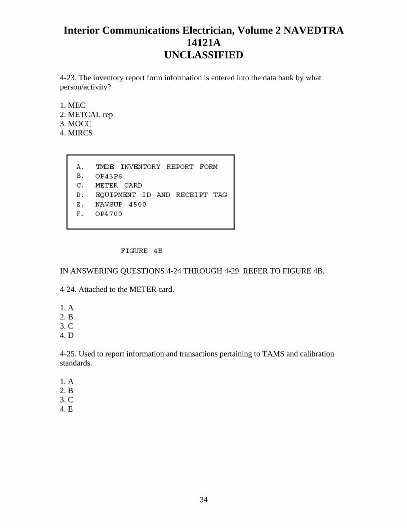
Interior Communications Electrician, Volume 2 NAVEDTRA 14121A
UNCLASSIFIED
4-23. The inventory report form information is entered into the data bank by what person/activity? 1. MEC 2. METCAL rep 3. MOCC 4. MIRCS IN ANSWERING QUESTIONS 4-24 THROUGH 4-29. REFER TO FIGURE 4B. 4-24. Attached to the METER card. 1. A 2. B 3. C 4. D 4-25. Used to report information and transactions pertaining to TAMS and calibration standards. 1. A 2. B 3. C 4. E
34

Interior Communications Electrician, Volume 2 NAVEDTRA 14121A
UNCLASSIFIED
4-26. Provides the initial input of data pertaining to TAMS equipment and calibration. 1. A 2. D 3. E 4. F 4-27. Bears the same control number as the METER card. 1. A 2. B 3. C 4. D 4-28. What document is used to forward questions, recommendations, and comments pertaining to MEASURE to concerned authorities? 1. A MEASURE referral card 2. A METER card 3. A TMDE inventory report form 4. An equipment ID and receipt tag 4-29. Which, if any, of the following copies of the receipt and ID tags are sent to the MOCC? 1. White 2. Pink 3. Green 4. None of the above 4-30. A calibrated label is used when which of the following conditions is met? 1. A specific tolerance is requested by the user 2. A specified condition requested cannot be met 3. The instrument fails at more than one test point within its range 4. All parameters to be tested are within tolerance
35

Interior Communications Electrician, Volume 2 NAVEDTRA 14121A
UNCLASSIFIED
4-31. What label/tag must be used when certain conditions must be known to the user and/or the calibration technician? 1. USER CALIBRATION 2. CALIBRATED 3. SPECIAL CALIBRATION 4. NO CALIBRATION REQUIRED 4-32. Which of the following labels requires that an instrument must be calibrated before it can be used? 1. CALIBRATED--REFER TO REPORT 2. CALIBRATION VOID IF SEAL BROKEN 3. CLEANED FOR OXYGEN USE 4. INACTIVE 4-33. The overall security, orientation, education, and training program is the responsibility of what person? 1. The commanding officer 2. The executive officer 3. The security officer 4. The engineer officer 4-34. Ways by which you can help make personnel security conscious include which of the following methods? 1. Stressing the importance of security and the penalties for violating security regulations 2. Relating the techniques that enemies have used to acquire classified information 3. Using posters in appropriate places as reminders of an individual’s duties concerning security matters 4. All of the above 4-35. What is the best means of developing individuals and teams into efficient working units? 1. Teaching by the show-and-tell method 2. Drilling and practicing on the job 3. Showing technical films and closed-circuit television programs 4. Conducting classroom lectures and informal group discussions
36

Interior Communications Electrician, Volume 2 NAVEDTRA 14121A
UNCLASSIFIED
4-36. The PQS program is designed to help you train your personnel for which of the following reasons? 1. To qualify for advancement 2. To discharge their leadership responsibilities 3. To perform their assigned duties 4. To become familiar with off-ship IC equipment and systems 4-37. Each qualification standard has four main subdivisions. What series is for watch standers? 1. 100 2. 200 3. 300 4. 400 4-38. What section (series) of PQS breaks down the equipment or systems to be studied into functional sections? 1. 100 2. 200 3. 300 4. 400 4-39. What section of the PQS is used to record the individual’s satisfactory completion of an item? 1. Theory 2. Qualification 3. Watchstation 4. System 4-40. Which of the following factors determines whether you receive either a slight or fatal shock? 1. Amount and duration of current flow 2. Parts of the body involved 3. Frequency of current 4. Each of the above
37

Interior Communications Electrician, Volume 2 NAVEDTRA 14121A
UNCLASSIFIED
4-41. What amperage is usually fatal if it lasts for 1 second or more? 1. 1 mA 2. 10 mA 3. 50 mA 4. 100 mA 4-42. Doors to switch and fuse boxes should be closed except under which of the following conditions? 1. When replacing fuses 2. When the area around the box is not manned 3. During battle stations 4. After knock-off of ship’s work 4-43. What individual must give approval to work on energized circuits? 1. Executive officer 2. Engineer officer 3. Commanding officer 4. Division officer 4-44. Should a situation arise where a doubt exists as to the application of a particular directive or precaution, what measures should be taken? 1. Those that will achieve maximum safety 2. Those that will achieve minimum safety 3. Higher authority should be contacted 4. Division officer’s advice should be followed 4-45. Which, if any, of the following NSTM chapters gives clear and concise electrical safety precautions that should be required study material for all hands? 1. 555 2. 430 3. 300 4. None of the above
38

Interior Communications Electrician, Volume 2 NAVEDTRA 14121A
UNCLASSIFIED
4-46. What piece of software, used in PMS, has a section devoted to safety precautions? 1. Weekly schedule 2. Work center PMS manual 3. Maintenance requirement card 4. Quarterly schedule 4-47. What is the best way to control any fire? 1. Use a 1 1/2-inch fire hose 2. Use a CO2 fire extinguisher 3. Use a PKP fire extinguisher 4. Do not let the fire happen 4-48. Which of the following agents should be used to fight electrical fires? 1. PKP 2. CO2 3. Water 4. AFFF 4-49. A technician working on a live circuit can help avoid accidents by taking which of the following precautions? 1. Removing rings, watches, and loose clothing before starting work 2. Wearing rubber gloves on both hands 3. Using insulated hand tools 4. All of the above 4-50. When more than one repairman is working on circuits that have a common supply, what procedure should be used for tagging circuits and removing tags? 1. Only one repairman tags the supply and removes the tag when the work is completed 2. At least two repairmen tag the supply; one repairman removes the tags when the work is completed 3. Each repairman tags the supply and removes only his/her tag when his/her work is completed 4. Each repairman tags the supply; the repairman completing his/her work last removes the tags
39

Interior Communications Electrician, Volume 2 NAVEDTRA 14121A
UNCLASSIFIED
4-51. What individual must grant permission before a person can go aloft in-port? 1. Officer of the deck 2. Engineer officer 3. Commanding officer 4. Command duty officer 4-52. What two hazardous voltages may be encountered when the ship’s service telephone system is connected to a shore exchange? 1. 115 volts ac and 220 volts ac 2. 220 volts ac and 48 volts dc 3. 115 volts ac and 90 volts ac 4. 90 volts ac and 48 volts dc 4-53. Which, if any, of the following switchboards has greatly reduced hazards to operators and repairmen? 1. Live front 2. Semi-dead front 3. Dead front 4. None of the above 4-54. Fuses of what maximum rating may be removed from a circuit before it is de-energized? 1. 10 amperes only 2. 15 amperes only 3. 25 amperes only 4. Any rating 4-55. What is the purpose of having an on-the-scene observer when you are working on a live circuit? 1. To ensure that all safety precautions are followed and to run errands 2. To ensure that all safety precautions are followed and to give first aid if necessary 3. To deliver messages and to locate specifications in NSTM, chapter 300 4. Each of the above
40

Interior Communications Electrician, Volume 2 NAVEDTRA 14121A
UNCLASSIFIED
4-56. Extension cords used with portable electric tools should NOT exceed what maximum length? 1. 25 ft 2. 50 ft 3. 100 ft 4. 200 ft 4-57. Naval regulations provide that no alterations are permitted to be made to ships until authorized by what command or individual? 1. Type commander 2. Commanding officer 3. Naval Sea Systems Command 4. Chief of Naval Operations 4-58. The shop supervisor is responsible for checking and inspecting completed repairs. 1. True 2. False 4-59. You can ensure proper personnel employment by the use of which of the following documents? 1. Quarterly schedule 2. Cycle schedule 3. Weekly work schedule 4. MRC (job card) 4-60. Which of the following statements is true concerning an MRC (job card)? 1. Cards are made out for a standard system and cannot be modified 2. Card job procedures are not in any sequential order 3. Cards can only be used on certain ships 4. Cards should be tailored for use on your ship through the use of the PMS feedback report
41

Interior Communications Electrician, Volume 2 NAVEDTRA 14121A
UNCLASSIFIED
4-61. When a job is received by a repair facility, when should the planning commence? 1. As soon as possible 2. When the job is started 3. One week after receipt of the job 4. The same day the job is received 4-62. Except when dealing with a sincere personal problem, what is the correct procedure to use when you must talk with one of a subgroup supervisor’s subordinates? 1. Talk to the person alone 2. Talk to the subgroup supervisor; then talk to the person 3. Have the subgroup supervisor accompany the person 4. Talk to the person alone; then talk to the subgroup supervisor 4-63. Which of the following is the correct priority for planning and scheduling work? 1. Routine, deferred, urgent 2. Urgent, routine, deferred 3. Urgent, deferred, routine 4. Routine, urgent, deferred 4-64. Which of the following information should be considered in determining the priority of a task (job)? 1. The ship’s schedule and the effect the equipment will have on the ability of the ship to perform its mission 2. Whether the work requires someone with special skills 3. Whether or not all the required parts and materials are available 4. All of the above 4-65. What OPNAV form is used to defer a maintenance action? 1. 4790/2K 2. 4790/2R 3. 4790/P1 4. 4790/2L
42

Interior Communications Electrician, Volume 2 NAVEDTRA 14121A
UNCLASSIFIED
4-66. What is the advantage of assigning a difficult or complex job to a less experienced person working under close supervision instead of to a more experienced person? 1. You can assign a low priority to the job 2. You will give the less experienced person a chance to gain experience in such tasks 3. You will not have to furnish a drawing or general statement about the job 4. You will not have to inspect the job after it is completed 4-67. Which of the following factors should you consider when planning a shipboard maintenance action or repair work? 1. Size of the job 2. Material needed and what material is available 3. Priority of the job 4. Each of the above 4-68. The work center supervisor should review the week’s work with which of the following personnel to determine which jobs need to be done right away? 1. The division officer 2. The chief engineer 3. The executive officer 4. The commanding officer 4-69. Which of the following is one of the main purposes for inspecting a job after it is finished? 1. To sign off the job order 2. To evaluate the worker’s skills and knowledge 3. To evaluate the priority assigned to the job 4. To estimate the man-hours for the job 4-70. In estimating time to complete a task, which of the following factors is NOT your responsibility? 1. Time for another shop to do its job 2. Time to be spent in other activities, such as drills 3. Rate at which personnel can do the work 4. Priority of the various jobs assigned to your shop
43

Interior Communications Electrician, Volume 2 NAVEDTRA 14121A
UNCLASSIFIED
4-71. The number of individuals who can work effectively on a job at the same time is an important factor when making which of the following estimates? 1. The amount of material that will be wasted on the job 2. The kind of materials the job requires 3. The time it takes to complete a job 4. The time that will be lost to drills, inspections, and work parties 4-72. When work is sent to an outside activity, what OPNAV form should you use? 1. 4790/2Q and 4790/2K 2. 4790/2K and 4790/2L 3. 4790/2R only 4. 4790/2L only 4-73. Estimating the materials required for a certain repair job is often more difficult than estimating the time and labor required for the job. 1. True 2. False 4-74. Which of the following is a good way to get a handle on what is happening during each step of a job? 1. Ask the commanding officer 2. Question the chief engineer 3. Talk to the command master chief 4. Consult the ship’s master training schedule and monthly training plan 4-75. Which of the following documents are NOT useful in planning a job? 1. Rate training manuals 2. Ship’s drawings 3. Blueprints 4. Manufacturers’ technical manuals 4-76. Which of the following is NOT a duty of supply officers? 1. Buy material 2. Stow material 3. Make out the abandon ship bill 4. Account for most types of stores
44

Interior Communications Electrician, Volume 2 NAVEDTRA 14121A
UNCLASSIFIED
4-77. Which of the following information will you NOT likely find on the nameplate of a piece of equipment? 1. Serial number, stock number, and model number 2. Operating values, such as volts, current, and speed 3. Manufacturer’s name 4. Materials required for repairs 4-78. To locate repair materials not specified in the instructions accompanying a job, which of the following is/are excellent sources to use? 1. Ships’ plans, blueprints, and drawings 2. Engineering log book 3. Engineer’s bell book 4. Gyro maintenance log 4-79. All materials in the supply system are assigned which of the following numbers? 1. Part number 2. Job sequence number 3. Stock number 4. Social security number 4-80. The administration and supervision of maintenance and repair of the gyrocompass is the responsibility of which of the following personnel? 1. Gyro technician 2. Gyro shop personnel 3. Commanding officer 4. Gyro officer 4-81. After a casualty occurs, a CASREP should be submitted within what maximum period of time? 1. 12 hr 2. 18 hr 3. 24 hr 4. 48 hr
45

Interior Communications Electrician, Volume 2 NAVEDTRA 14121A
UNCLASSIFIED
4-82. Once a casualty is reported, what person/office should receive hard copies of CASREP messages? 1. CNO, fleet commanders, and ship’s parts control center 2. CNO, squadron commanders, and commanding officer 3. CNO, fleet commanders, and commanding officer 4. Commanding officer, squadron commanders, and ship’s parts control center 4-83. What is the maximum number of casualty categories used by all commands except for NAVEDTRACOMs? 1. Five 2. Two 3. Three 4. Four 4-84. An UPDATE CASREP contains information similar to that submitted in which of the following documents? 1. CASCOR 2. CASCAAN 3. SITREP 4. INITIAL CASREP 4-85. What type of CASREP identifies the status of the casualty and parts and/or assistance requirements? 1. UPDATE 2. INITIAL 3. CANCEL 4. CORRECT 4-86. A CORRECT CASREP should be submitted in which of the following situations? 1. When the casualty has been corrected 2. Within 24 hours of discovery of a casualty 3. When a casualty is over 48 hours old 4. When there is more information to report than originally known
46

Interior Communications Electrician, Volume 2 NAVEDTRA 14121A
UNCLASSIFIED
47
4-87. What total number of casualty categories do NAVEDTRACOM activities use? 1. Six 2. Five 3. Three 4. Four 4-88. For additional information on the Status of Resources and Training System (SORTS), you should refer to what chapters of NWP 1-03.1? 1. 3 and 4 2. 1 and 4 3. 1 and 5 4. 5 and 6 4-89. The casualty category is NOT required in the casualty set in all CASREPs. 1. True 2. False 4-90. The decision logic tree is used for which of the following purposes? 1. To determine the unit’s overall status category 2. To determine the M-rating 3. To determine the casualty category and whether or not a CASREP is required 4. Each of the above 4-91. The serialization for a CASREP will appear in which, if any, of the following places? 1. After the message classification line 2. Before the message classification line 3. In the message classification line 4. None of the above 4-92. Which of the following statements is true concerning the serial numbers for CASREPs? 1. They are in non-sequential order 2. They are sequential from 1 through 99 3. New sequence numbers start after submission of number 99 4. They are sequential from 1 through 999

Interior Communications Electrician, Volume 2 NAVEDTRA 14121A
UNCLASSIFIED
Textbook Assignment: Chapters 5, “Quality Assurance”. ASSIGNMENT 5 5-1. The achievement of an effective QA program depends on which of the following factors? 1. Speed of repair, special skills, and knowledge 2. Speed of repair, special skills, and prevention of maintenance problems 3. Knowledge, prevention of maintenance problems, and speed of repairs 4. Knowledge, prevention of maintenance problems, and special skills 5-2. What number is assigned to the SQCI by the QAO for use on all forms and tags that require initials as proof that certified tests and inspections were completed? 1. Social security number 2. Stock number 3. Personal serial number 4. Personal pin number 5-3. The QA manual for each TYCOM sets forth which of the following requirements? 1. Maximum QA requirements 2. Minimum QA requirements 3. Specific QA requirements for ships 4. Specific QA requirements for shore 5-4. The instructions contained in the QA manual apply to what organizations? 1. Shore activities only 2. Combat ships only 3. Repair ships only 4. Every ship and activity of the force 5-5. If conflicts exist between the QA manual and previously issued letters and transmittals by appropriate force commanders, the letters and transmittals take precedence. 1. True 2. False
48

Interior Communications Electrician, Volume 2 NAVEDTRA 14121A
UNCLASSIFIED
5-6. Which of the following is considered part of job execution? 1. Completing QA forms 2. Meeting controlled material requirements 3. Training personnel 4. Auditing programs 5-7. The administrative part of the QA program consists of which of the following parts? 1. Preparing work procedures 2. Requisitioning material 3. Monitoring programs 4. Testing and recertifying 5-8. Technical specifications can be ruled out in the interest of completing the job quickly. 1. True 2. False 5-9. Which of the following factors spawned the need for the development of the QA program? 1. The ever-increasing technical complexity of present-day surface ships and submarines 2. The ever-increasing workload of the work centers aboard ship 3. The ever-increasing lack of formal training for technicians aboard ship 4. Each of the above 5-10. A certain level of confidence required in the reliability of repairs made is known as what type of level? 1. Level of assurance 2. Level of control 3. Level of essentiality 4. Level of reliability 5-11. Which of the following is one of the main goals of the QA program? 1. To ensure every repair of any failed equipment is documented 2. To increase the time between equipment failure 3. To ensure the safety of personnel while working on SUBSAFE items 4. To protect personnel from hazardous conditions
49

Interior Communications Electrician, Volume 2 NAVEDTRA 14121A
UNCLASSIFIED
5-12. What is the most difficult part of planning a job? 1. Determining which technical specification sources are applicable to a particular job 2. Determining the number of personnel required to accomplish a specific job 3. Determining what material is needed 4. Determining how much time is required to accomplish the job 5-13. What person is responsible for maintaining the ship’s QA records and test and inspection reports? 1. The type commander 2. The commanding officer 3. The repair officer 4. The quality assurance officer 5-14. The QA program (Navy) begins with which of the following personnel? 1. The commanding officer of the ship 2. The type commander 3. The quality assurance officer 4. The commanders in chief of the fleet 5-15. What person is responsible to the force commander for QA in the maintenance and repair of the ship? 1. The type commander 2. The commanding officer 3. The quality assurance officer 4. The ship quality control inspector 5-16. What person(s) provide(s) instruction, policy, and overall direction for implementation and operation of the force QA program? 1. The commanders in chief of the fleet 2. The type commanders 3. The commanding officer 4. The quality assurance officer
50

Interior Communications Electrician, Volume 2 NAVEDTRA 14121A
UNCLASSIFIED
5-17. Which of the following personnel is responsible for initiating a departure from specification report? 1. The work center supervisor 2. The quality control inspector 3. The person finding or causing the departure 4. The quality assurance officer 5-18. The quality assurance officer is responsible to the commanding officer for which of the following tasks? 1. Coordinating the ship’s 3-M training 2. Conducting the ship’s QA training 3. Reviewing procedures and work packages prepared by the ship before submission to the engineer 4. Reviewing personnel records to ensure that everyone is qualified as quality assurance inspectors 5-19. The SQCI is responsible for which of the following actions? 1. Planning work for the work center 2. Scheduling preventive maintenance 3. Assigning work to maintenance personnel 4. Inspecting all work for conformance to specifications 5-20. Which of the following personnel must know the specifications limits of a job and the purpose of these limits? 1. Executive officer only 2. Leading petty officer only 3. Chief petty officer only 4. Each person involved in the job 5-21. Any technical or administrative directive that defines repair criteria is known as a/an 1. calibration 2. acceptance 3. specification 4. inspection record
51

Interior Communications Electrician, Volume 2 NAVEDTRA 14121A
UNCLASSIFIED
5-22. What term is defined as a written instruction designed to produce acceptable and reliable products, whether produced or repaired? 1. Inspection 2. Procedure 3. Process 4. SUBSAFE 5-23. The effective operation of a successful QA program requires the effort of which of the following personnel? 1. Commanding officer only 2. Quality assurance officer only 3. Engineering officer only 4. All hands 5-24. The person with the most direct concern for quality workmanship within a work center is which of the following personnel? 1. The production supervisor 2. The shop craftsmen 3. The division officer 4. The department head 5-25. Which of the following is an example of a QA action performed following the completion of a series of tasks? 1. Final inspection 2. In-process inspection 3. Receiving inspection 4. Screening inspection 5-26. What type of inspection determines the condition of material, maintenance requirements, and disposition and correctness of accompanying records and documents? 1. Final inspection 2. Midterm inspection 3. In-process inspection 4. Receiving or screening inspection
52

Interior Communications Electrician, Volume 2 NAVEDTRA 14121A
UNCLASSIFIED
5-27. Which of the following actions is NOT considered to be part of the in-process inspection? 1. A periodic or special evaluation of details, plans, policies, procedures, product directives, and records 2. The witnessing of task performance 3. The application of torque and functional testing 4. Adjusting, assembling, servicing, and installation 5-28. What person is responsible for coordinating and administering the QA program within a work center? 1. SQCI 2. QAO 3. Work center supervisor 4. Division officer 5-29. Which of the following is NOT a responsibility of the SQCI? 1. Developing a thorough understanding of the QA program 2. Assigning jobs that require a work package 3. Maintaining records and files to support the QA program 4. Ensuring that all work center personnel are familiar with applicable QA manuals by conducting training 5-30. What term describes a management function that attempts to eliminate defective products? 1. Quality assurance 2. Quality control 3. Audit 4. Controlled material 5-31. Which of the following personnel is/are responsible for conducting internal audits as required and taking corrective action on noted discrepancies? 1. Division officer 2. Quality assurance officer 3. SQCI 4. All of the above
53

Interior Communications Electrician, Volume 2 NAVEDTRA 14121A
UNCLASSIFIED
5-32. Which of the following personnel is responsible for inspecting, segregating, stowing, and issuing controlled material? 1. CMPO 2. SQCI 3. Division officer 4. Work center supervisor 5-33. What QA function is performed to identify production standards or material characteristics during manufacture or a repair cycle that may not be detectable during final inspection? 1. Quality assurance 2. Quality control 3. In-process inspection 4. Technical repair standardization 5-34. Alternate SQCIs (backup personnel) do not need to have the same degree of qualifications and will not be given the same responsibilities as normally assigned SQCIs. 1. True 2. False 5-35. CMPOs are trained and qualified by the QA supervisor and are normally of what paygrade(s)? 1. E3 and E4 2. E4 only 3. E5 only 4. E4 and E5 5-36. The commanding officer assigns the primary duty of which of the following personnel in writing according to the QA manual? 1. SQCI 2. QAO 3. CMPO 4. PAO
54

Interior Communications Electrician, Volume 2 NAVEDTRA 14121A
UNCLASSIFIED
5-37. What person is responsible for training and qualifying the work center SQCI? 1. Quality assurance officer 2. Division officer 3. Ship quality control inspector 4. Quality assurance supervisor 5-38. Which of the following personnel is/are given a written examination as well as an interview before becoming qualified to do the assigned job? 1. QAO 2. CMPO only 3. SQCI only 4. CMPO and SQCI 5-39. In addition to a good personnel orientation program, which of the following elements are required for an effective QA program? 1. A comprehensive training program, use of proper repair procedures, and a uniform liberty policy 2. A comprehensive training program, use of proper repair procedures, and uniform inspection procedures 3. Use of proper repair procedures, use of new tools and equipment, and uniform inspection procedures 4. Use of new tools and equipment, proper working environment, and uniform liberty policy 5-40. What number provides traceability from the work package to other certification documentation? 1. Job control number 2. Identification number 3. Serial number 4. Stock number 5-41. What term best describes when an authorized representative approves specific services rendered? 1. Quality control 2. Inspection 3. Acceptance 4. Inspection record
55

Interior Communications Electrician, Volume 2 NAVEDTRA 14121A
UNCLASSIFIED
5-42. The examination and listing of components and services to determine whether they conform to specified requirements is defined by what term? 1. Acceptance 2. Inspection 3. In-process inspection 4. Calibration 5-43. If, during the repair process, you must change the original scope of the work to be performed, what procedure must you initiate? 1. Revision 2. Addendum 3. Automated work request 4. Controlled work package 5-44. Which of the following information is NOT provided to a supervisor in a CWP? 1. QA form instructions 2. QC procedures 3. QC techniques 4. Stowage location of SUBSAFE material 5-45. What procedure should you follow if, during a repair process involving simultaneous performance of procedure steps, the steps are in different locations? 1. Reject the job and send the (CWP back to planning 2. Make a copy of the CWP with its documentation for each job site 3. Use locally developed practices 4. Have the CWP at one job site only 5-46. What term describes the documentation contained inside a CWP? 1. Revision 2. Enclosures 3. Addendum 4. Specifications
56

Interior Communications Electrician, Volume 2 NAVEDTRA 14121A
UNCLASSIFIED
5-47. What term indicates the impact that catastrophic failure of the associated part or equipment would have on the ship’s mission capability and personnel safety? 1. Levels of assurance 2. Levels of essentiality 3. Levels of necessity 4. Levels of controls 5-48. Which, if any, of the following levels of assurance normally requires both quality control and tests and/or inspection methods? 1. A 2. B 3. C 4. None of the above 5-49. What level of assurance provides for “as necessary” verification techniques? 1. A 2. B 3. C 4. I 5-50. Which of the following is NOT a description of controlled material? 1. It has special markings 2. It has accountability throughout the repair or manufacturing process 3. It is stowed separately 4. It must be open purchased 5-51. What term is defined as the degrees of control measures required to assure reliability of repairs made to a system, subsystem, or component? 1. In-process inspection 2. Levels of assurance 3. Levels of control 4. Levels of essentiality
57

Interior Communications Electrician, Volume 2 NAVEDTRA 14121A
UNCLASSIFIED
5-52. What person must inspect controlled material for required attributes before it can be used in a system or component? 1. QAO 2. SQCI 3. CMPO 4. DCPO 5-53. SUBSAFE requirements are split into what total number of categories? 1. Five 2. Two 3. Three 4. Four 5-54. What term is defined as any submarine system determined by NAVSEA to require the special material or operability requirements of the SUBSAFE program? 1. SUBSAFE boundary 2. SUBSAFE barrier 3. SUBSAFE material 4. SUBSAFE system 5-55. What term is defined as the record of objective evidence establishing the requisite quality of the material, component, or work done? 1. Procedure 2. Documentation 3. Controlled work package 4. Departure from specification 5-56. Which of the following problems may cause a worker to fail to report a departure from specification? 1. Lack of training 2. Lack of time for adequate planning 3. Lack of adequate inspection 4. Each of the above
58

Interior Communications Electrician, Volume 2 NAVEDTRA 14121A
UNCLASSIFIED
5-57. When there is a lack of compliance with cognizant technical documents, drawings, or work procedures during a maintenance action that will not be corrected before the ship gets underway, what document is required? 1. OPNAV Form 4790/2 2. OPNAV Form 4790/21 3. ACN 4. Departure from specification 5-58. What type of departure from specification must be approved by the appropriate authority? 1. Major only 2. Minor only 3. Semi-minor only 4. Any departure from specification 5-59. What are the two types of departure from specifications? 1. Major and minor 2. Major and semi-minor 3. Minor and semi-minor 4. Semi-minor and minimal 5-60. Which of the following terms is defined as a set of actions written in a special sequential order by which maintenance action, a test, or an inspection is done using specific guidelines, tools, and equipment? 1. Process 2. Procedure 3. Documentation 4. Audit
59

Interior Communications Electrician, Volume 2 NAVEDTRA 14121A
UNCLASSIFIED
60
5-61. What QA form lists all tests and inspections that must be at each step? 1. 12 2. 13 3. 16 4. 17 5-62. What QA form is attached by supply QA, or shop personnel to provide traceability of accepted controlled material from receipt inspection through final inspection? 1. 7 2. 2 3. 3 4. 4A 5-63. What QA form is used by the CMPO to provide a standard inventory record of controlled material received and issued? 1. 7 2. 8 3. 8A 4. 9 5-64. What QA form is used to identify and control material and equipment in a positive manner from ship to repair shop? 1. 9 2. 9A 3. 4A 4. 4

Interior Communications Electrician, Volume 2 NAVEDTRA 14121A
UNCLASSIFIED
Textbook Assignment: Chapter 6, “Ship’s Drawings and Diagrams”. ASSIGNMENT 6 6-1. Which of the following are reproduced copies of mechanical or other types of technical drawings? 1. Electrical prints 2. Electronic prints 3. Blueprints 4. Electromechanical drawings 6-2. What is the meaning of the term “blueprint reading”? 1. Reading aloud the printed matter in the legends 2. Giving oral directions to the operator of the machine reproducing the blueprint 3. Interpreting the ideas expressed on drawings 4. Reading related matter to help you understand the blueprint symbols 6-3. Which of the following printing processes produces prints with black, blue, or maroon lines on a white background? 1. VanDyke printing 2. Ozalid printing 3. Black-and-white printing 4. Mimeograph printing 6-4. Which of the following processes may be used for reproducing small drawings or sketches? 1. Mimeographing 2. Dittoing 3. Photostating 4. Each of the above 6-5. Blueprints are printed directly on sensitized paper from which of the following sources? 1. A drawing or tracing on translucent paper or cloth 2. An original drawing on a steel plate 3. A photographic negative of a drawing 4. A drawing copied onto a clear glass sheet
61

Interior Communications Electrician, Volume 2 NAVEDTRA 14121A
UNCLASSIFIED
6-6. Which of the following references gives the list of graphic symbols for electrical and electronic diagrams? 1. MIL-STD-100E 2. MIL-STD-15 (Part No. 2) 3. ANSI Y32.2 4. ANSI Y39.2 6-7. In which corner of a blueprint is the title block located? 1. Upper right 2. Lower left 3. Upper left 4. Lower right 6-8. In which comer of a blueprint is the revision block usually found? 1. Lower right 2. Lower left 3. Upper right 4. Upper left 6-9. If a blueprint bearing the drawing number 5123476-C is revised, what will be the revised drawing number of the revised print? 1. 5123476-C1 2. 5123476-D 3. 5123476-1C 4. 1-5123476 6-10. If the actual length of an object is 5 inches, what is the length of its drawing on a blueprint with a scale of 2” = 1”? 1. 1/2 in. 2. 2 1/2 in. 3. 5 in . 4. 10 in.
62

Interior Communications Electrician, Volume 2 NAVEDTRA 14121A
UNCLASSIFIED
6-11. What number on a blueprint serves the same purpose as numbers and letters printed on the borders of maps? 1. Zone 2. Reference 3. Scale 4. Drawing 6-12. Although the scale of a blueprint indicates the dimensions of the drawing relative to the actual size of the object, you should not measure the drawing to determine the actual size of the object because of which of the following reasons? 1. You must verify the accuracy of the scale 2. You must verify the accuracy of the blueprint 3. You must avoid errors made because of incorrect interpretation of the scale 4. You must avoid any errors made in the original drawing 6-13. Which scale is divided into decimal graduations? 1. Graphic 2. Engineers’ 3. Metric 4. Architects’ 6-14. Which scale indicates the number of feet or miles represented by an inch? 1. Architects’ 2. Engineers’ 3. Graphic 4. Metric 6-15. Which block of a blueprint lists the parts and materials used on or required by the print concerned? 1. Application 2. Title 3. Notes and Specifications 4. Bill of material
63

Interior Communications Electrician, Volume 2 NAVEDTRA 14121A
UNCLASSIFIED
6-16. What information appears in the Used On column of a blueprint’s application block? 1. Model number or equivalent designation of the assembled unit of which the part is a component 2. Drawing or model number of the next larger assembly to which the drawing applies 3. Authentication for the blueprint 4. Second part of a two-detail blueprint 6-17. In which comer of a blueprint is the legend of symbols located? 1. Upper right 2. Lower right 3. Upper left 4. Lower left 6-18. A finish mark on a blueprint indicates that the surface of the part must be: 1. tempered 2. painted or plated 3. machined 4. polished and painted 6-19. What type of plan is submitted with bids, or other plans, before award of a contract? 1. Standard plans 2. Preliminary plans 3. Working plans 4. Contract plans 6-20. What type of plans are a designated group of plans illustrating features considered necessary for shipboard reference? 1. Standard plans 2. Corrected plans 3. Type plans 4. On board plans
64

Interior Communications Electrician, Volume 2 NAVEDTRA 14121A
UNCLASSIFIED
6-21. Plans that illustrate the general arrangement of equipment, systems, or components that are not necessarily subject to strict compliance as to details are what type of plans? 1. Type 2. Working 3. Contract 4. Contract guidance 6-22. Which of the following is NOT a necessary practice in the handling and stowage of blueprints? 1. Keep prints out of strong sunlight 2. Keep prints stowed in their proper place 3. Keep prints out of strong, magnetic fields 4. Keep prints folded properly 6-23. Which type of diagram shows the individual connections within a unit and the physical arrangement of the component? 1. Isometric wiring diagram 2. Pictorial wiring diagram 3. Schematic diagram 4. Wiring (connection) diagram 6-24. Which type of diagram uses graphic symbols to show how a circuit functions electrically? 1. Schematic diagram 2. Isometric wiring diagram 3. Wiring (connection) diagram 4. Pictorial wiring diagram 6-25. Which type of diagram shows how each conductor is connected within the various connection boxes of an electrical circuit or system? 1. Elementary wiring diagram 2. Schematic diagram 3. Isometric wiring diagram 4. Single-line diagram
65

Interior Communications Electrician, Volume 2 NAVEDTRA 14121A
UNCLASSIFIED
6-26. A cable classified as semivital has what color tag? 1. Gray 2. Yellow 3. Red 4. Blue 6-27. In the new electrical cable numbering system in use aboard navy ships, what letter designation is used for ship’s service lighting? 1. C 2. D 3. L 4. N 6-28. Aboard ship, a cable designated2-FB-411B3 has what voltage? 1. 120 2. 220 3. 350 4. 450 6-29. What is the number 2 in significance of the parentheses in a cable designated (1-132-1)-3E-4P-A(2)? 1. Second deck of a power main 2. Second deck of the ship 3. Port side of the ship 4. 220-volt cable 6-30. What does the C in the cable designation 4SGC-2N-4S indicate? 1. Type of service, communications 2. Third switchboard 3. Cable 4. Third generator supplying the switchboard
66

Interior Communications Electrician, Volume 2 NAVEDTRA 14121A
UNCLASSIFIED
6-31. Electrical prints are usually more difficult to read than electronic prints. 1. True 2. False 6-32. For a complete understanding of synchros, gyros, analog computing elements, and accelerometers, what type of drawing should you use? 1. Electromechanical 2. Interconnection 3. Mechanical 4. Electrical 6-33. What type of diagrams are used in the operation and maintenance of digital computers? 1. Schematic diagrams 2. Logic diagrams 3. Isometric wiring diagrams 4. Block diagrams 6-34. Which of the following diagrams uses geometric figures to represent major components of a piece of equipment or system? 1. Single-line diagrams 2. Schematic diagrams 3. Block diagrams 4. Isometric wiring diagrams 6-35. Similar unit and other shipboard machinery and equipment that comprise a group is assigned a separate series of consecutive numbers beginning with 1. Which of the following is the correct way to start and end the numbering? 1. Port to starboard, aft to forward 2. Forward to aft, starboard to port 3. Forward to aft, port to starboard 4. Aft port, forward starboard
67

Interior Communications Electrician, Volume 2 NAVEDTRA 14121A
UNCLASSIFIED
68
6-36. Electrical distribution panels and control panels are given identification numbers made up of three numbers separated by hyphens. What does the first number indicate? 1. Longitudinal location 2. Transverse location 3. Port location 4. Vertical level unit is normally accessible 6-37. Main switchboard or switchgear groups supplied power directly from ship’s service generators have which of the following designations? 1. 1S 2. 1A 3. 2K 4. 2E

Interior Communications Electrician, Volume 2 NAVEDTRA 14121A
UNCLASSIFIED
Textbook Assignment: Chapter 7, “Maintenance”. ASSIGNMENT 7 7-1. What diagrams are most often used by IC Electricians? 1. Block diagrams 2. Electronic and electrical schematics 3. Mechanical drawings 4. Wiring diagrams 7-2. Block diagrams and signal flow charts are least useful for which of the following functions? 1. To describe functions of IC equipment 2. To help personnel understand how IC systems work 3. To show personnel how to maintain IC equipment 4. To show the relationship of one partial schematic to another 7-3. The SIMM, through use of symbology, blocks, and color shading, is a new information display technique that eliminates the requirements for a well-informed technician. 1. True 2. False 7-4. The index of the SIMM is organized on what basis? 1. According to cabinet nomenclature and circuit elements 2. According to functional entity 3. According to major assemblies and contained assemblies 4. According to circuit elements only 7-5. Which of the following is NOT a building block of the SIMM? 1. Blocked schematic 2. Blocked text 3. Blocked diagram 4. Precise-access blocked diagram
69

Interior Communications Electrician, Volume 2 NAVEDTRA 14121A
UNCLASSIFIED
7-6. The blue-shaded area of a blocked schematic shows the functional features of a circuit. 1. True 2. False 7-7. Detailed cabling information between all assemblies is shown on which of following types of illustrations? 1. Blocked schematic 2. Electrical/electronic schematic 3. Mechanical drawing 4. Precise-access blocked diagram 7-8. Where are the turn-on and checkout procedures located on the operating procedures page? 1. On one horizontal line across the top of the page 2. Down the left-hand side of the page 3. Down the right-hand side of the page 4. In the lower right-hand corner 7-9. On a maintenance dependency chart, what does a solid black rectangle with white lettering represent? 1. A front panel indicator or event recognizable from outside of the cabinet 2. An event recognizable inside of the cabinet 3. An external test point 4. An internal test point 7-10. Subassemblies, such as synchro motors, that frequently are identified by non-readily translatable military-type numbers also include what other information? 1. Navy Standard Stock Numbers 2. Suitable substitute assembly numbers 3. Allowance parts list number of the equipment 4. Sufficient meaningful data for ordering purposes
70

Interior Communications Electrician, Volume 2 NAVEDTRA 14121A
UNCLASSIFIED
7-11. The technique of isolating a fault is based upon a positive approach, which is an analysis of circuitry to verify that things that should have happened did happen. 1. True 2. False 7-12. An action or availability of a signal at a point in a circuit is the definition of what term? 1. Circuit element 2. Functional entity 3. Event 4. Dependency marker 7-13. An individual piece or part for which no further breakdown can be made insofar as fault isolation is concerned is the definition of what term? 1. Event 2. Functional entity 3. Circuit element 4. Functional marker 7-14. For each major circuit, there is a corresponding MDC consistent with which of the following diagrams? 1. Precise-access blocked diagrams 2. Electronic schematics 3. Electrical schematics 4. Blueprints 7-15. Equipment and assembly halftones and line drawings are overlaid with a grid, on which coordinates are placed to assist in parts location. What color is the grid? 1. Yellow 2. Green 3. Red 4. Blue
71

Interior Communications Electrician, Volume 2 NAVEDTRA 14121A
UNCLASSIFIED
7-16. The keyed text method of presentation is used with all EXCEPT which of the following diagrams? 1. Schematic diagram 2. Precise-access blocked diagram 3. Wiring diagram 4. Overall block diagram 7-17. What is the name given to wiring that interconnects subassemblies in IC equipment cabinets? 1. Chassis wiring 2. Cabinet wiring 3. Cable wiring 4. Harness wiring 7-18. Which of the following is the first step of troubleshooting chassis wiring? 1. Smell the components 2. Visually inspect the wiring harness from terminal to terminal 3. Conduct continuity tests 4. Replace the circuit cards 7-19. What is the best way to repair an installed wiring harness that contains damaged wires? 1. Remove the old harness completely, pull the damaged wires, and replace them one at a time, form fitting each replacement wire as it is installed 2. Fabricate another harness to replace it, using a plywood jig 3. Remove the damaged wires one at a time and replace each with a new straight wire 4. Install a new harness alongside the old one 7-20. You have replaced wires in a chassis wiring harness. When hand pressure is applied, the replacement wire between cable clamps should sag by what amount? 1. 1 in. 2. 3/4 in. 3. 1/2 in. 4. 1/4 in.
72

Interior Communications Electrician, Volume 2 NAVEDTRA 14121A
UNCLASSIFIED
7-21. What is the most reliable method for locating faults in chassis wiring? 1. Trial and error 2. Substitution of parts 3. Signal tracing 4. Ground checking 7-22. Measures taken to achieve maximum efficiency, ensure continuity of service, and lengthen useful life of equipment or systems are known as: 1. General repair 2. Major repair 3. Corrective maintenance 4. Preventive maintenance 7-23. Locating and correcting troubles on malfunctioning systems or equipment is referred to as: 1. Preventive maintenance 2. Corrective maintenance 3. Major repair 4. General repair 7-24. Equipment inspections fall into what total number of categories? 1. One 2. Two 3. Three 4. Four 7-25. Which of the following items enables the technician to make an intelligent evaluation of the operating capabilities and efficiency of equipment? 1. Manufacturer’s instruction book 2. Maintenance Requirement Card 3. Isometric diagram 4. Block diagram
73

Interior Communications Electrician, Volume 2 NAVEDTRA 14121A
UNCLASSIFIED
7-26. Which of the following methods of checking a discrepancy may disclose frayed or broken wiring? 1. Operational check 2. Performance test 3. Equipment light-off 4. Visual in-place inspection 7-27. The steps through which a technician gains information about a casualty, isolates and repairs the faulty component, and clearly understands the reason for the malfunction is known as: 1. Troubleshooting 2. Corrective maintenance 3. Preventive maintenance 4. System analyzing 7-28. Before reinstalling a piece of equipment, the senior IC Electrician should make sure which of the following operations is/are carried out? 1. Visual inspection 2. Operational check 3. Performance test 4. All of the above 7-29. To avoid damaging a voltmeter when testing a circuit of unknown voltage, what should you do? 1. Set the voltmeter on the highest scale first and work to a lower scale 2. Set the voltmeter on the lowest scale first and work to a higher scale 3. Check the manufacturers’ technical manuals for proper voltage levels 4. Ensure the meter is set to read resistance and not voltage 7-30. What will be the indication if the internal resistance of the voltmeter and multiplier is approximately the same in value to the resistance of the circuit under test? 1. A lower voltage than the actual voltage present 2. A higher voltage than the actual voltage present 3. The voltage will be the same as the actual voltage 4. The voltage will vary in the circuit
74

Interior Communications Electrician, Volume 2 NAVEDTRA 14121A
UNCLASSIFIED
7-31. Which of the following is a disadvantage of taking voltage measurements? 1. It is time consuming 2. It is less accurate 3. It requires working on an energized circuit 4. There is no way of knowing the correct voltage 7-32. At which of the following times should you discharge filter capacitors with a shorting probe? 1. Before resistance checks 2. Before capacitor leads are disconnected 3. Both 1 and 2 above 4. Before voltage checks 7-33. The waveforms shown in maintenance books should match exactly the actual waveform displayed on an oscilloscope? 1. True 2. False 7-34. Equipment characteristics and usage can cause distortion of an observed waveform. Which of the following situations can cause this distortion? 1. The leads of the test oscilloscope may not be placed in the same manner as those preparing the reference waveform 2. A type of test oscilloscope having different values of input impedance, sweep duration, or frequency response may have been used 3. The vertical or horizontal amplitudes of the reference and test amplitudes of the reference and test patterns may not be proportional 4. Each of the above 7-35. Which of the following is NOT an advantage of using a transistor amplifier over a vacuum-tube amplifier? 1. Transistors have longer life and less power consumption 2. Transistors are more efficient in using dc power and operating at low voltages 3. Transistors lack microphonics signals and have little or no ac hum 4. Transistors can dissipate more heat
75

Interior Communications Electrician, Volume 2 NAVEDTRA 14121A
UNCLASSIFIED
7-36. The most desirable method of matching source impedance to input impedance is by what type of coupling? 1. Resistor-capacitor 2. Transformer 3. Direct 4. Resistor 7-37. The most common emitter configuration may be used to match a high source resistance by the addition of what component in the base lead? 1. Series capacitor 2. Parallel capacitor 3. Series resistor 4. Parallel resistor 7-38. If a speaker is connected directly to the output of a transistor, there is little or no audio gain due to which of the following factors? 1. Characteristics of the transistor 2. High impedance of the speaker 3. The transistor has no gain, due to impedance mismatch 4. Circuit configuration 7-39. What type of connection should you use to get a highly reliable 4-speaker system? 1. Series connection of two sets of speakers in parallel 2. Series strip connection 3. Parallel speakers in series with another speaker 4. Parallel connection of two sets of speakers in series 7-40. In a constant-voltage speaker system, the distribution of audio power is affected only slightly or not at all by which of the following factors? 1. Addition to the system 2. Changes to the system 3. Unmatched impedance 4. Each of the above
76

Interior Communications Electrician, Volume 2 NAVEDTRA 14121A
UNCLASSIFIED
IN ANSWERING QUESTION 7-41, REFER TO FIGURE 7-19 OF THE TEXT. 7-41. What is the output voltage of the speaker system shown? 1. 120.0 V 2. 90.0 V 3. 70.0 V 4. 50.0 V 7-42. You have a transformer whose 8-ohm secondary is connected to an 8-ohm speaker. What should be the impedance of the primary to deliver 50 watts from a 70-volt line? 1. 50 ohms 2. 100 ohms 3. 150 ohms 4. 200 ohms 7-43. What is an electronic module? 1. A piece of electronic equipment consisting of replaceable assemblies 2. An assembly constructed of standardized electronic components 3. A package of wired electronic components capable of functioning as an assembly when used with other assemblies 4. A package of standardized electronic units assembled to function as a self-contained system 7-44. What is one of the most common quick part identification methods developed by commercial manufacturers? 1. Number points of interest on the schematic, and a guide provided to locate the numbered points 2. A grid imposed over a drawing of the board and a corresponding table that lists the part location 3. Parts labeled directly on the schematic 4. Each of the above 7-45. When you are circuit tracing a translucent printed-circuit board, which of the following methods will make the job easier? 1. Use a mirror to observe the opposite side 2. Use an ohmmeter for point to point tracing 3. Use a lighted bulb under the board 4. Use a grid over the printed circuit portion
77

Interior Communications Electrician, Volume 2 NAVEDTRA 14121A
UNCLASSIFIED
7-46. The shop supervisor should ensure that personnel using test equipment on printed-circuit boards employ which of the following safe work practices? 1. Observe polarities in measuring circuit resistance 2. Start signal application at a sufficiently low level 3. Secure all components before turning the power on 4. Each of the above 7-47. When you are trying to find an acceptable substitute for a specific relay, which of the following specifications should be considered? 1. Coil resistance only 2. Current rating only 3. Voltage rating only 4. Voltage rating, current rating, coil resistance, contact type, and arrangement of contacts 7-48. When you are inspecting a de-energized IC switchboard, in addition to a close visual inspection, what other check(s) should you perform? 1. Shake all electrical connections to see that they are tight 2. Shake all mechanical parts to see that they work properly 3. Make sure the supports of bus work will keep bus bars from touching grounded parts 4. All of the above 7-49. By virtue of the rating, an IC Electrician is authorized to repair switchboard instruments. 1. True 2. False 7-50. In general, why are protective circuits NOT tested under actual operating conditions? 1. Too many different types of circuits are involved 2. Equipment damage is likely to result 3. Repair parts are not available 4. The possibility of human error is too high
78

Interior Communications Electrician, Volume 2 NAVEDTRA 14121A
UNCLASSIFIED
79
7-51. Before you start repairing an energized switchboard, permission to do so must come from your Commanding Officer. 1. True 2. False 7-52. Which of the following practices will help prevent damage to a current transformer, but NOT a potential transformer? 1. Short circuiting the secondary of the transformer 2. Short circuiting the primary of the transformer 3. Opening the secondary of the transformer while the current is flowing through the primary 4. Each of the above