Embed Size (px)
Citation preview

Multi-user Interference Cancellat ion in DS-CDMA with Forward Error Correction
b~
Kitw Kar Yan Wong
-4 thesis submitted to the Department of Electrical and Computer Engineering
in conformity nit h the requirements for the degree of Master of Science (Engineering)
Queen's University Kingston? Ontario, Canada
September 2000
Copyright @ Kitty Kar Yan Wang: 2000

National Library 1+1 OfCa*,
Acquisitions and Acquisitions et Bi bliog raphic Services services bibliographiques 395 WeUinglon Street 395. r w Welihgm Ottawa ON KlAON4 O(iswaON KlAONI Canada Canada
The author has granted a non- exclusive licence dowing the National Library of Canada to reproduce, loan, distribute or sel1 copies of this thesis in microform, paper or electronic formats.
L'auteur a accordé une licence non exclusive permettant à la Bibliothèque nationale du Canada de reproduire, prêter, distribuer ou vendre des copies de cette thèse sous la forme de microfiche/film, de reproduction sur papier ou sur fomat électronique.
The author retains ownership of the L'auteur conserve la propriété du copyright in this thesis. Neither the droit d'auteur qui protège cette thèse. thesis nor substantial extracts fkom it Ni la thèse ni des extraits substantiels may be printed or othenvise de celle-ci ne doivent être imprimés reproduced without the author's ou autrement reproduits sans son permission. autorisation.
Abstract
In a code division multiple access (CDM-4) system, the presence of the multiple access
interference (LI-41) limits the number of users that can simultaneously communicate
over the channel. To overcome the detrimental effects of the M-41, the use of a multi-
user detection (MUD) algorithm is needed. Many MUD algorithms proposed in the
literature involve the use of complex maximum-a-posteriori (&lAP) decoders that
prohibits their use in many practical applications. The goal of this research project
is to design a lou- complexity algorithm that is targeted at the 384 kbps application
in t hird-generation wideband CDMA (WCDMA).
In this thesis, the use of multi-user interference cancellation in a F~rward Error
Correction (FEC) coded CDMA system is studied. The proposed algorithm combines
linear MUD and iterative interference cancellation. It involves iterative decoding and
soft interference cancellation that is based on FEC decoder decision feedback. The
investigation of the iterative algorithm uses a full CDMA system mode1 which involves
three types of commonly used spreading sequences: GoId. Kasami, and extended S(2)
sequences. Computer simulations are used in this thesis to obtain the performance
of the proposed algorithm using each of the spreading sequences.
For an AWGN channel, the classical CDM-4 detector with no MUD supports 5
high-bit-rate users in WCDMA a t a bit-error-rate of for the constraint length 7,
rate-; convolutionally coded system. The iterative algorithm proposed in this thesis
doubles the number of users in the targeted application.

Acknowledgement s
I would like to thank Dr. Peter McLane, my supervisor, for his support, guidance.
and patience. Without his help, the completion of this thesis would not be possible.
He is also a great addition t o Our softball team.
Special thanks for Dr. Mohsen Hossenian from Harris Corporation, Canada, who
suggested the use of the extended S ( 2 ) code in our simulations. This made Our work
much more meaningful, and gave some insight as why the es~ended S(2) code was
chosen by 3GPP.
Thanks to al1 members in Peter's lab for making it a great place to work. Specif-
ically: Jean .Au, for his help a t the early stage of this project on clarifj4ng some key
concepts; Frederick Lee, for his efforts in proof-reading my thesis; Chan-Tong Lam,
for his knowledge in LaSex: Elvis Chen. for his expertise in programming language,
LaTex, his effort in proof-reading my thesis? and his patience; Pawel Dmochowski and
JValaa Hamouda, for making the lab a friendly place.
Xlso, thanks to Dr. Fady -4lajaji: Dr. Steven Blostein, and Dr. Naraig Majikian for
their comments on this thesis. The quality of this thesis write-up n7as much improved.
Finallyv, thank you to my family and friends for their care and support.
iii
Table of Contents
Table of Contents iv
List of Abbreviations xiii
List of Symbols xiv
1 Introduction 1
1.1 Motivation . . . . . . . . . . . . . . . . . . . . . . . . . . . . . . . . . 1
1.2 Performance Measure . . . . . . . . . . . . . . . . . . . . . . . . . . . 3
1.3 Literature Sun-ey . . . . . . . . . . . . . . . . . . . . . . . . . . . . . 3
1.4 Thesis Contribution . . . . . . . . . . . . . . . . . . . . . . . . . . . . 6 -
. . . . . . . . . . . . . . . . . . . . . . . . . . . . . . . 1 Thesis Outline 1
2 General Background 9
2.1 Oven-ien- of a CDhl-4 system . . . . . . . . . . . . . . . . . . . . . . 9
2.2 User capacity of a C D X 4 system . . . . . . . . . . . . . . . . . . . . 12
2 -3 On hl ultiple Access Interference Cancellation . . . . . . . . . . . . . . 14
2.3.1 Parallel Interference Cancellation . . . . . . . . . . . . . . . . 15
2.3.2 Serial Interference Cancellation . . . . . . . . . . . . . . . . . 16
2.4 Convolutional Codes . . . . . . . . . . . . . . . . . . . . . . . . . . . 18
. 2.4.1 Convolutional Encoder [l 2: 31 . . . . . . . . . . . . . . . . . 18
. . 2.1.2 Convolutional Decoder[l 2 31 . . . . . . . . . . . . . . . . . . 20
2 . 4 3 The ITiterbi Algorithm (1 . . . . . . . . . . . . . . . . . . . 21

. . . . . . . . . . . . . . . . . . . . . . . . . . . . 2.44 Interleaving 23
2.5 CDMA with FEC . . . . . . . . . . . . . . . . . . . . . . . . . . . . . 24
The Discrete Mode1 28
. . . . . . . . . . . . . . . . . . . . 3.1 Iterative Interference Cancellation 29
3.1.1 Brute Force Interference Cancellation . . . . . . . . . . . . . . 3C
3.1.2 Partial Interference Cancellation . . . . . . . . . . . . . . . . . 36
3.1.3 Soft Interference Cancellation . . . . . . . . . . . . . . . . . . 40
. . . . . . . . . . . . . . . . . . . . . . . . . . . . . . . 3.2 Pre-processing 43
3.2.1 The Decorrelating detector . . . . . . . . . . . . . . . . . . . . 44
3.2.2 The Minimum Mean-Squared-Error Detector . . . . . . . . . . 45
3.2.3 Iterative Interference Cancellation with Pre-processor . . . . . 45
. . . . . . . . . . . . . . . . . . . . . . . . . . . . 3.3 Chapter Surnmal 49
4 The Signature Sequences 52
. . . . . . . . . . . . . . . . 4.1 Maximal Length Shift Register Sequences 53
. . . . . . . . . . . . . . . . . . . . . . . . . . . 4.2 The Gold Sequences 58
. . . . . . . . . . . . . . . . . . . . . . . . . . 4.3 The Kasami Sequences 59
. . . . . . . . . . . . . . . . . . . . . . 4.4 The extended S(2) Sequences 60
. . . . . . . . . . . . . . . . . . . . . . . . . . . . 4.5 Chapter Summary 62
5 Iterative Interference Canceilation for High Data Rate Users in
WCDMA 63
. . . . . . . . . . . . . . . . . . . . . . . . . . . . 5.1 System parameters 63
5.2 Iterative Interference Cancellation with different spreading sequences 64
. . . . . . . . . . . . . . . . . 5.2.1 Spreading a i th Gold sequences 64 c. C . . . . . . . . . . . . . . . . 5.2.2 Spreading with Kasami sequences (a
. . . . . . . . . . . . 5.2.3 Spreading with extended S(2) sequences 82
3 Multi-user interference Cancellation with Increased Processing Gain . 87

5.4 Chapter Summary . . . . . . . . . . . . . . . . . . . . . . . . . . . . SS
6 Conclusions 91
6.1 Conclusions . . . . . . . . . . . . . . . . . . . . . . . . . . . . . . . . 91
6.2 Suggestions for Future Work . . . . . . . . . . . . . . . . . . . . . . . 92
Bibliography 94
A Approximating the cross-correlation p 98
B Simulations and the Confidence Intervals 100
Vita 101

List of Tables
A list of m-sequences generated using primitive polynomial f (D) =
I t D + D 2 . . . . . . . . . . . . . . . . . . . * . . . . . . , . . . . .
Mapping from quantery S(2) sequences to extended S(2) sequences . .
Number of available sequences of each spreading code family - - - . .
Error Profile for the Brute Force IIC algorithm using tdegree Gold
code at an SXR of 5dB . . . . . . . . . . . . . . . . . . . . . . . . . -
The number of bits required to achieve different confidence inten-als -

List of Figures
2.1 -4 general ~V...user CDh1.A transmit ter . . . . . . . . . . . . . . . . . . 10
2.2 Conventional ikL-user CDM-4 receiver . . . . . . . . . . . . . . . . . . 11
. . . . . 2.3 .A general ;',.user parallel interference cancellation algorithm 15
. . . . . . 2.4 -4 general user serial interference cancellation algorithm 11
. . . . . . . . . . . . . 2.5 -4 general convolutional encoder of rate.k,/n, 19
. . . . . . . . . . 2.6 -4 rate-$. constraint length 3' convolutional encoder 40
2.7 State diagram for the rate-;: constraint length 3. encoder shown in
Figure2.6 . . . . . . . . . . . . . . . . . . . . . . . . . . . . . . . . . 21
. . . . . . . 33 2.8 Trellis diagram for the rate-!' constraint length 3 encoder -- . . . . . . . 2.9 The add-compare-select process of the I'iterbi -Ilgorithm 23
2.10 .A typical interference cancellation procedure . . . . . . . . . . . . . . 24
. . . . . . . 2.11 The error propagation diagram for the Viterbi Algorithm 25
2.12 -AA%-u~erCDhI~4systemn-ithFEC . . . . . . . . . . . . . . . . . . 25
2.13 Conventional CDh4-A receiver with FEC . . . . . . . . . . . . . . . . 2s
. . . . . . . . 3.1 -4 general Iterative Interference Cancellation Algorithm 29
3.2 .A 2-user Iterative Brute Force Interference Cancellation .A lgorithm . . 30
3.3 Performance of the Brute Force IIC Algorithm on a 9-user system with
crosçcorrelation p = 0.20 . . . . . . . . . . . . . . . . . . . . . . . . . 33
3.4 Performance of the Brute Force IIC -ilgorithm on a 9-user system with
. . . . . . . . . . . . . . . . . . . . . . . . . cross-correlation p = (3.35 33
viii
Performance of the Brute Force IIC Algoritiim on a 9-user system with
cross-correlation p = 0.30 . . . . . . . . . . . . . . . . . . . . . . . . . Performance of the Brute Force IIC Algorithm on a l e u s e r system
with cross-correlation p = 0.25 . . . . . . . . . . . . . . . . . . . . . . Performance of the Brute Force IIC Algorithm on a Il-user system
with cross-correlation p = 0.25 . . . . . . . . . . . . . . . . . . . . . . Performance of the Brute Force IIC Algorithm on a 12-user p t e m
with cross-correlation p = 0.25 . . . . . . . . . . . . . . . . . . . . . .
-4 2-user Partial Iterative Interference Cancellation Algorithm . . . .
Cornparison on different values of the cancellation fractions on a 9-user
system wit h cross-correlation p = 0.25 . . . . . . . . . . . . . . . . . .
Performance of Partial IIC Algorithm with cancellation fraction y' =
60% on a 9-user system with cross-correlation p = 0.30 . . . . . . . .
Performance of Partial IIC Algorithm with cancellation fractions y l =
50%, y* = 5O%, y3 = 60% and y4 = 60% on a 9-user system with
cross-correlation p = 0.30 . . - . . . . . . . . . . . . . . . . . . . . . . The merging branches . . . . . . . . . . . . . . . . . . . . . . . . . .
Performance of the Soft IIC .Algorithm on a 9-user system with cross-
correlation p = 0.30 . . . . . . . . . . . . . . . . . . . . . . . . . . . .
Performance of the decorrelôting detector and MMSE detector on a
9-user system with cross-correlation p = 0.25 . . . . . . . . . . . . . .
Performance of the pre-processor-aided Brute Force IIC -4lgorithm on
a 10-user system with cross-correlation p = 0.25 . . . . . . . . . . . .
Performance of the pre-processor-aided Brute Force IIC -4igorithm on
a 10-user system with cross-correlation p = 0.35 . . . . . . . . . . . .
Performance of the pre-processor-aided Brute Force IIC Algorit hm on
a 10-user system with cross-correlat ion p = 0.45 . . . . . . . . . . . .

3.19 Performance of the pre-processor-aided Brute Force IIC Algorit hm on
a 13-user system with crosçcorrelation p = 0.45 . . . . . . . . . . . .
The structure for a r-degree Linear Feedback Shift Register . . - . . .
-4 2-stage m-sequence generator . . . . . . . . . . . . . . . . . . . . .
-Autocorrelation function for an m-sequence with chip duration Tc and
period :t'Tc . . . . . . . . . . . . . . . . . . . . . . . . . . . . . . . .
Generating a Gold sequence of period K=7 . . . . . . . . . . . . . . .
Generating a Kasami sequence of penod N=4 . . . . - - . . . . . . .
The S (2) sequence generator . . . . . . . . . . . . . . . . . . . . . . .
Performance of the Brute Force IIC .Ilgorithm on a 9-user system with
processing gain of 7, spreading with Gold sequences. . . . . . . . . . .
The ,Yu-stage Preliminary Interference Cancellation -Algorithm . . . .
Performance of the Bmte Force IIC ,Ilgorit hm nvit h a %stage prelim-
inary IC on a 9-user system ni th processing gain of ï 1 spreading with
Gold sequences. . . . . . . . . . . . . . . . . . . . . . . . . . . . . . . Performance of the Brute Force IIC .ilgorithm combined with a 2-stage
Partial Preliminary IC on a 9-user system with processing gain of 7.
spreading with Gold sequences. . . . . . . . . . . . . . . . . . . . . . Performance of the Brute Force IIC ,Ilgorithm combined with a 2-
stage Soj? Preliminary IC on a 9-user system with processing gain of
7. spreading with Gold sequences. . . . . . . . . . . . . . . . . . . . .
Performance of the 3.IMSE pre-processor on a 9-user system with pro-
cessing gain of 7, spreading with Gold sequences. . . . . . . . . . . .
Performance of the Brute Force IIC algorithm on a 9-user systern with
processing gain of 7: spreading with Kasami sequences. . . . . . . . . Performance of the Partial IIC .Algorithm on a 9-user system with
processing gain of 7, spreading with Kasami sequences. . . . . . . . .

5.9 Performance of the Soft IIC Algorithm on a 9-user q t e m 11-ith pro- -- cessing gain of 7. spreading n-ith Iiasami sequences. . . . . . . . . . . t t
5-10 Performance of the Pre-processor-aided Brute Force IIC algorithm on
a %user system mlth processing gain of 7. spreading n-ith Iiasami se-
quences. . . . . . . . . . . . . . . . . . . . . . . . . . . . . . . . . . . 78
5-11 Performance of the Pre-processor-aided Partial IIC -ilgorithm on a 9-
user system with processing gain of 7: spreading with Kasami sequences. 79
5.12 Performance of the Pre-processor-aided Soft IIC Algorit hm on a 9-user
systern with processing gain of 7. spreading wïth Kasami sequences. . 79
5.13 -4 cornparison on average MMSE detector and optimal MMSE detector 80
5.14 Performance of the Pre-processor-aided Soft IIC -4lgorithm on a 10-
user system with processing gain of 7: spreading with Kasami sequences. 81
5.15 Performance of the Pm-processor-aided Soft IIC Algorithm on a 11-
user -tem with processing gain of 7. spreading with Iiasami sequences. 81
5.16 Performance of the Brute Force IIC Algorithm on a 9-user system 119th
processing gain of 7. spreading with extended S(2) sequences. . . . . .
5.17 Performance of the Partial IIC -Algorithm on a 9-user system with
processing gain of 7. spreading nith estended S(2) sequences. . . . . .
5.18 Performance of the Sofl IIC Algorithm on a 9-user system with pro-
cessing gain of 7. spreading with estended S(2) sequences. . . . . . .
5.19 Performance of the Pre-processor-aided Brute Force IIC Algorithm on
a 9-user system with processing gain of 7. spreading with estended
S (2) sequences. . . . . . . . . . . . . . . . . . . . . . . . . . . . . . .
5.20 Performance of the Soft IIC .Algorithm on a 10-user system with pro-
cessing gain of 7. spreading with estended S(2) sequences. . . . . . .
5.21 Performance of the Soft IIC algorithm on a Il-user system with pro-
cessing gain of 7. spreading with estended S(2) sequences. . . . . . ,

5.22 Performance of the Pre-processor-aided Soft IIC algorithm on a Il-
user -stem nith processing gain of 7. spreading nith estended S(2)
sequences. . . . . . . . . . . . . . . . . . . . . . . . . . . . . . . . . . 86
5.23 Performance of the Pre-processor-aided Soft IIC aigorithm on a 12-
user system wlth processing gain of 7, spreading with estended S(2)
sequences. . . . . . . . . . . . . . . . . . . . . . . . . . . . . . . . . . 87
5.24 Performance of the Brute Force IIC AIgorithm on a 18-user sj-stem
using rate-f convolutional code with uncoded processing gain of 30 - 89
5.25 Performance of the Brute Force IIC Algorithm on a 18-user system
using rate-$ convolutionai code with uncoded processing gain of 30 . 89
sii
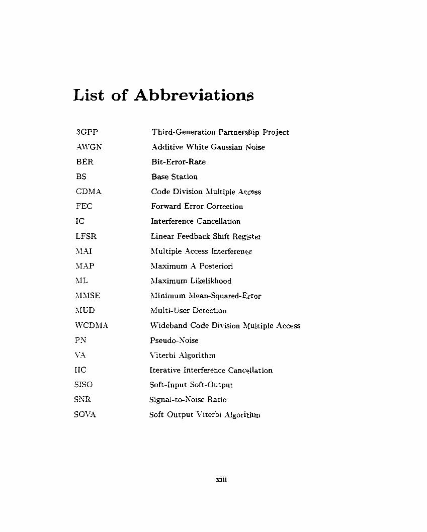
List of Abbreviations
Third-Generation P artne~bip Project
Additive White Gaussian I\ioise
Bit-Enor-Rate
Base Station
Code Division Multiple -4tcess
Fonvard Error Correction
Int erference Cancellat ion
Linear Feedback Shift Register
Multiple -4ccess Interference
3Iaximurn -1 Posteriori
&Ia,uimurn Likelikhood
$1 inimurn Mean-Squared-&-or
Multi-User Detection
Wideband Code Division Plfultiple -4ccess
Pseudo-Xoise
\.'iterbi ,Algorit hm
Iterative Interference Cancellatiori
Soft-Input Soft-Output
Signal-to-Soise Ratio
Soft Output Viterbi -1lgoritfim
xiii

List of Symbols
- b;
b - -1
&k -1
- . I re f ined b;
bi
PK sequence assigneci to the jch user
for uncoded system: ith information sjmbol of the jth user for coded system: ih interleaver output q m b o l of the jth user
tentative bit decision made for b;
finai bit decision made for 6;
the tentative bit decision made for b; a t the kth iteration
interleaver output sequence of the jth user
the tentative decision made for b, at the kt" iteration
the bit decision made for 6; by the preliminary IC algorithm.
for uncoded system: ith information symbol vector of al1 users for coded system: i th interleaver output vector of al1 users
symbol bandwidth
branch metric from the transition from state S;' at time i - 1 to state Si at time 1
baseband signal of the jth user
unit delay
i units delay
characteristic polynomial of the LFSR
polynomial that captures the the initial load of the LFSR
kth feedback coefficient of the LFSR
the ich encoder generator
generating polynomial
the pre-processor matris
siv
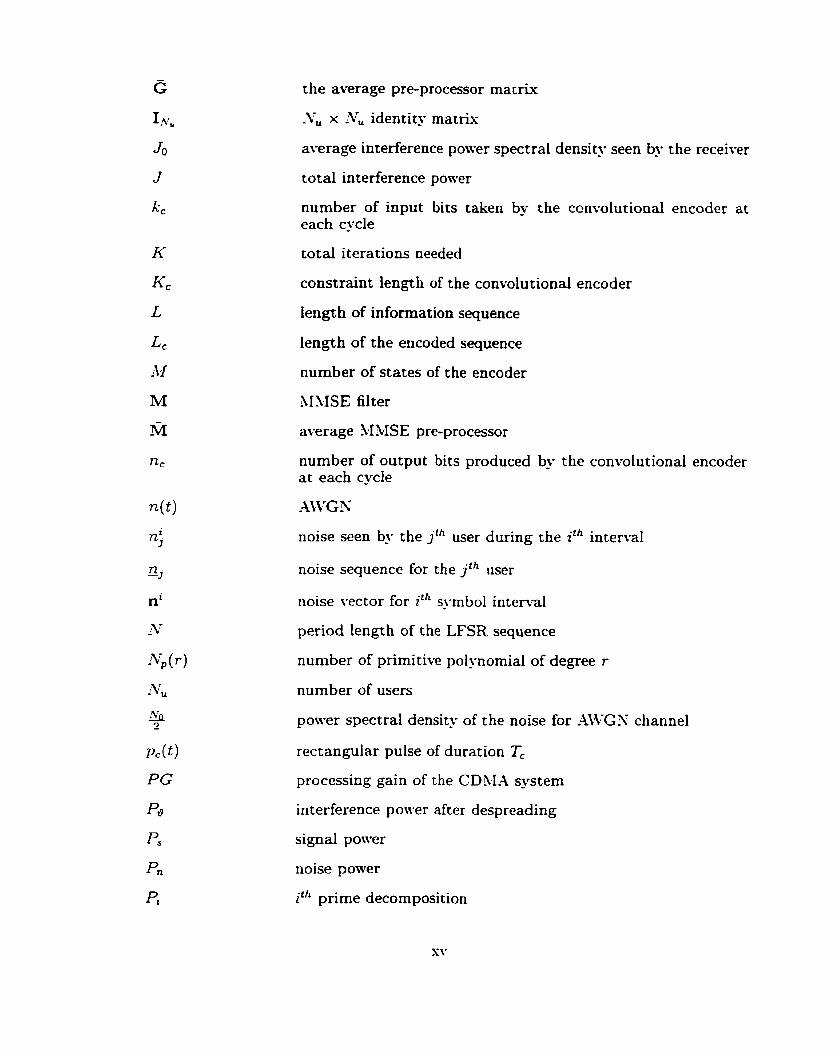
the average pre-processor matrix
-Y,, x :Vu identity matr~x
average interference power spectral density seen by the receiver
total interference ponTer
number of input bits taken by the ccn~olutional encoder at each cycle
total iterations needed
constraint length of the convolutional encoder
length of information sequence
length of the encoded sequence
number of States of the encoder
MMSE filter
average 34MSE pre-processor
number of output bits produced by the convolutional encoder at each cycle
noise seen by the j th user during the ith interval
noise sequence for the j th user
noise vector for i th syrnbol intenal
period length of the LFSR sequence
number of primitive polynomial of degree r
number of users
power spectral density of the noise for .AWGX channel
rectangular pulse of duration Tc
processing gain of the CDh.1-4 systern
interference power after despreading
signal power
noise ponrer
Ph prime decomposition
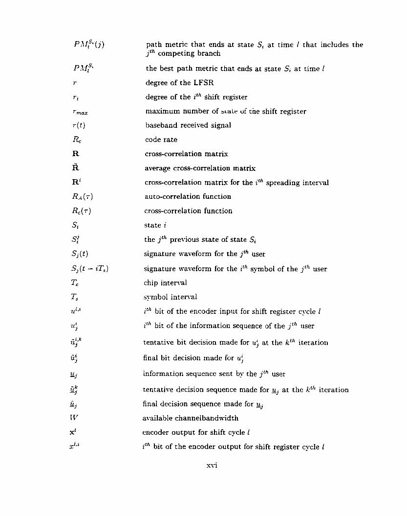
path metric that ends at stâte S, at time 1 that includes the j th competing branch
the best path metric that ends at state S, at time Z
degree of the LFSR
degree of the ith shift register
mâ.\=imum number of aie ut^ tne shift register
baseband received signal
code rate
cross-correlation matris
average cross-correlation matrix
cross-correlation matris for the ith spreading i n t e m l
auto-correlation function
cross-correlation function
state z
the jth previous state of state S,
signature waveform for the jîh user
signature waveform for the ith symbol of the jth user
chip interval
SJ-rnbol inten-al
i th bit of the encoder input for shift register cycle 1
it" bit of the information sequence of the j'" user
tentative bit decision made for u; at the kth iteration
final bit decision made for u;
information sequence sent by the j th user
tentative decision sequence made for 2, a t the kîh iteration
final decision sequence made for gj
available channelbandwidth
encoder output for shift cycle Z
i th bit of the encoder output for shift register cycle Z
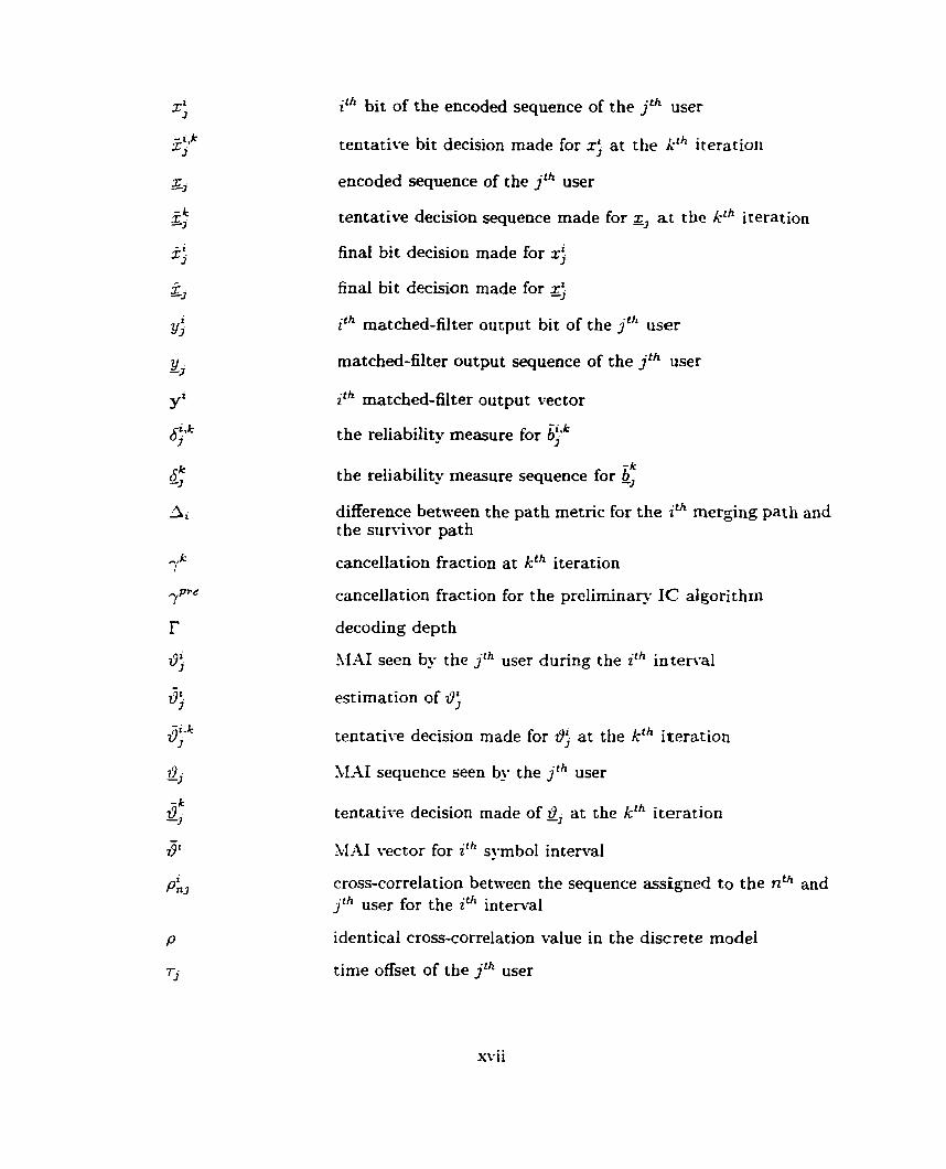
ith bit of the encoded sequence of the jth user
tentative bit decision made for x; at the kth iteration
encoded sequence of the j* user
tentative decision sequence made for z, at the kf"teration
final bit decision made for x;
final bit decision made for Z;
ith matched-filter output bit of the j th user
matched-filter output sequence of the jth user
ith matched-filter output vector
the reliability measure for &>k
the reliability rneasure sequence for 6: difference between the path metric for the ith merging path and the su-ivor path
cancellation fraction at kth iteration
cancellation fraction for the preliminary IC algorithm
decoding depth
3.1-41 seen by the j th user during the ith interval
estimation of I-,
tentative decision made for i9; at the kth iteration
SIAI sequence seen by the jth user
tentative decision made of z9, at the kth iteration
XIAI vector for ith symbol interval
cross-correlation between the sequence assigned to the nth and j th user for the ith interval
identical cross-correlation value in the discrete mode1
time offset of the j th user
svii
Chapter 1
Introduction
1.1 Motivation
The aim of the next-generation wireless network is to provide access to rnulti-media
services t hrough a universal persona1 communication device [4]. To achieve t his goal.
there is a need to improve both trafic capacity and service quality of esisting cellular
networks. Code Division Multiple -1ccess (CDM-4) is a spread-spectrum communica-
tien technique that offers solutions to the aforementioned problem [j]. Adopted by
the Telecornmunication Industry -i\ssociation. it is the standard platform for third-
generation persona1 cellular communication systems [6]. Unlike traditional multiple
access systems, CDM-4 allows al1 active users to transmit messages simultaneously
over the same channel bandtvidth. Alessages transmitted from each CDhll-1 user are
modulated a second time to a bandwidth much wider than necessary tvith a wide-
band noise-like signai called the pseudo-noise (PX) signal. This second modulation
is termed spreading. It alloms suppression of the multiple access interference (hl-41)
produced by other active users of the system provided that each user has a distinct
P N signzl. The amount of suppression depends on the cross-correlation properties
among the PN signals of al1 users as well as the ratio in bandwidth between the P N
signal and the information-bearing signal. This ratio. called the processing gain, is
crucial to the needed high spectral efficiency of CDM-4 systems. Due to the limited
wireless resources, the processing gain of a CDPVI-4 system is constrained by the avail-

able channel bandnidth. Hence. a typical CDbl-4 systern can only tolerate a fised
amount of 11-II. -4s a result. there exists a maximum number of active users that a
CDhl-4 system can support.
One way to expand user capacity is to rnodify the conventional CDlI-A detec-
tors [Tl. The conventional CDM-4 detector is composed of a bank of single-user
matched-filter receivers. each matched to the individual PX waveform assigned to
the corresponding user. This type of receiver structure performs independent data
detection for each user, neglects the presence of the other users. and is not optimal for
the non-Gaussian CDM-4 channel. Multi-user detection (MC'D) is a technique t hat
makes use of the MAI during the detection process to alleviate the disadvantages of
the conventional CDBIA detector [il. The optimal MUD algorithm derived by Verdu
[8, 91 is a maximum likelihood (ML) detection algorithm that performs joint detection
for al1 simultaneous users. This algorithm yields the minimum achievabie probability
of error in detecting CDM-4 signals and significantly improves the performance Gver
the conventional detectors. The improvement. however. is obtained at the espense
of a dramatic increase in computational complexity. n-hich grows esponentially with
the number of simultaneous users. Therefore. it is infeasible to implement the k r d u
algorit hm in practical applications.
,Mani sub-optimal hWD algorithms have been proposed that eshibit good perfor-
mance and complexity tradeoffs. Linear 11UD algorithms such as the decorrelating
detector [IO] and the minimum mean-squared-error (1IMSE) detector 111) are one
of the simpIer and earlier sub-optimum detectors proposed that give s a t i s f a c t o ~
performance by inverting the effect of the 11-41. The non-linear SICD scheme in-
volving interference cancellation (IC) is anot her popular approach t hat a t tempts to
remove the hi-41 from the received signal for each user before making data decisions
[12. 13. 14. 15. 16. 17. 18. 191.
The purpose of t his t hesis is to study various interference cancellation algorithms
for a CDM-JL system employing a fonvard error correction (FEC) scheme, and to

deveiop a low-complexiw suboptimal MUD scheme for the high-data-rate service
based on the Wideband-CDMA (WCDMA) [6] standard. In particular. this thesis
is focused on MUD schemes for the 384 kbps senlce in WCDhI.4. Homyever, the
additive white Gaussian noise (-4WGN) channel, a channel mode1 much simpler than
the models used in the WCDMA standard, is used. Combining both linear MUD and
iterative interference cancellation, a fairly low-complexity detection algorithm can be
designed to improve the user capacity of such systems, but at the cost of increased
delay.
1.2 Performance Measure
One of the most important performance measures in communications is the probabil-
ity of error or the bit-error-rate (BER). BER is defined as the probability of making
an error on an individual bit of information. It provides vital information conceming
the effectiveness of a given algorithm. In this thesis, the BER for a single-user system
in the absence of kL4I will be used as a benchmark for comparing the performance
of sub-optimal multi-user detectors. The particular MUD algorithm proposed in this
thesis has an iterative structure. Therefore, the nurnber of iterations needed for the
algorithm to converge to the single-user performance bound is also used as a figure of
merit. Since the system considered has a nonlinear structure due to both the FEC and
IC algorithms: a closed-form expression on the BER is very difficult to obtain. Thus,
cornputer simulations are used for determining the BER. For the research described
in this thesis, the goal is to achieve a BER of 10-~.
1.3 Literature Survey
The use of MUD to improve user capacity in CDMA communication systems is the
subject of much past and present research activity. In the early 198OYs, Verdu [20]
showed that the conventional matched-filter receiver is oniy individually optimum in
the sense that it gives optimal data detection for each individual user only when no
observation on the interfering users are allon-ed. 1;erdu [8. 91 Lias also derived and
analyzed the optimal detection algorithm that gives jointly optimal data decisions
based on the M L criterion. This algorithm searches through the set of al1 possible
input sequences and selects the one that yields the minimum achievable probabilit?.
of error. ,Ut hough the Verdu algorithm significantly improves the performance over
the conventional receiver, it suffers from a dramatic increase in the computational
complexity, which grows exponentially wïth the number of active users in the system.
This drawback has motivated researchers to seek low-complexi ty sub-optimal MUD
algorit hms.
The MUD algorithrns in the literature can be categorized into optimal. linear,
and nonlinear. Optimal MUD gives jointly optimal decisions on al1 user's bits based
on some optimality criterion. Recent work in this area combines MCID with FEC
schemes and makes use of the Turbo processing principle [21] to obtain an iterative
MUD algorithm that asymptotically achieves the optimal performance at the espense
of increasing delay [22' 23. 24: 25, 26. 271. In general. an iterative MGD algorithm
contains two soft-input soft-output (SISO) decoders. The first SISO decoder is a
multi-user rna.simum-a-posteriori (LLAP) decoder that reads the matched-filter output
of al1 the users and their a priori information to produce a set of soft measures on
the decoded bits. The second decoder consists of a bank of single-user decoders. each
uses the corresponding soft value produced by the first SISO decoder to generate the
a priori information for the particular user. -4 close loop through these two decoders
completes one iteration. The method of computing the soft values and the a priori
information depends on the particular opt imality criterion. In [22, 231 the optimal
iterative MGD algorithm based on the cross-eniropy minimization and its sub-optimal
implementation are derived by Moher. In [24]. an iterative MUD algorithm based on
the MAP criterion is proposed by Reed et al. In [25], Gamel and Geraniotis derived
their iterative receiver based on the MNSE criterion. Recently, Wang and Poor
[26, 271 derived their iterative hIUD algorithm based on an interference suppression
technique and M M E filtering. These iterative J K D algorithms generally give near-
optimal performance, but the use of the ven high complexity X 4 P decoders in these
algorithms prohibits their use in man'. practical applications.
Linear multi-user detection algorithms such as the decorrelating receiver [IO] and
the MMSE receiver [ll] make use of equalization techniques that perform linear trans-
formation on the receiver output to suppress the hl-AI. The decorrelating receivîr
completely eliminates the hl-41. but it also suffers from a channel noise enhancement
[il. The M'SE receiver, on the other hand. compromises between MAI rejection and
noise enhancement [7], but its linear structure limits its performance when compared
to other sub-optimal MUD algorithms. Xlthough these MUD algorithms do not pro-
vide near-optimal performance. their implementation sirnplicity makes them one of
the best candidates for practical multi-user detectors [28].
Nonlinear MUD such as interference cancellation attempts to rernove the 11-11 be-
fore making data decisions in order to improve the system performance with moderate
computational complexity [29]. Interference cancellation can be classified into serial
and parallel 1161. Serial cancellation ranks the users according to their received power
strengths and successively performs interference cancellation and data detection on
a user-by-user basis. ParalIel interference cancellation. on the other hand. at tempts
to remove interference from each user simultaneously. Serial cancellation generally
performs better when the users are received with different ponrer strengths. but it
also suffers from an extended delay compared to parallel cancellation (991. Many
serial-cancellation-based algorit hms (12. 13. l-l. 151 and parallel-cancellation-based
algorithms [16. 17, 18. 191 have been proposed. These algorithms focus mainly on
an uncoded system with no FEC. Less work on interference cancellation has been
conducted on a coded system.
The work in this thesis is focused on a convolutional coded CDMA system with
a sub-optimal MUD algorithm that combines Iinear MUD and parallel interference
cancellation. The main reference for the partial interference cancellation scheme used
in this thesis is the work by Simon and Divsalar [16]. The fundamental background
on XIUD can be found in the test by \>rd6 [il. It provides an estensive treatment
on different MUD algorithms including their performance as well as their cornplesit!-.
General communications texts used for reference include Proakis and Salehi [30].
Peterson et al (311. and Cooper and McGillum [32]. Information on the different
proposals submitted for the third generation mobile communications can be found
in the text by Ojanpera and Prasad [6] and the summary paper by Zeng et al [-Il.
References on the spreading sequences include texts by Golomb [33]. and Peterson
and Weldon [34]; a tutonal paper by Dinan and Jabbariin [35]: and the document by
the third generation partnership project group [36]. References on the convolut ional
code and its components can be found in Wilson [l], Wicker [2]. and \Ïterbi and
Omura [3]. The development of the soft output Viterbi algorithm can be found in a
paper by Hagenauer and Hoeher (371.
1.4 Thesis Contribution
1. Most of the literature on MUD with coding concentrates on a discrete mode1
which does not involve any particular class of spreading codes. This thesis uses
a full system mode1 and considers AICD performance for convolutional codes
with three types of spreading sequexxes: Gold. Kasami and estended S(2). The
thesis is focused on the 384 kbps third-generation \I'CDL.I,4 semice in a 5 hWiz
bandn-idth.
2. -4 novel MUD algorithm is considered for multi-user decoding. The decoding
algorithm is iterative and it has been found that the quality of the detected
data used in the first iteration is crucial for the convergence of the iterative
process. -4ccordingly: various pre-processors are applied to the matched-filter
outputs to improve the initial decoder decisions. In the following iterations, the
pre-processor is no longer used and the soft interference cancellation algorithm
is applied to the matched filter outputs until convergence is attained. In the
soft interference canceliation algorithm, the quality of the decoded outputs of
the previous iteration is used to aid the decoding process.
3. For an AWGN channel, it is found that the iterative decoder described abot-e can
double the number of users in the target application relative to the conventional
CDM-4 detector.
4. For the Gold codes, it is found that performance is limited by the fact that
the channel crosscorrelation matrix becomes singular. This fact has not been
found in the papers included in the literature survey.
5. In the case of using long codes, where only consecutive segments of the codes
are used in each transmissiont it was found that using the time average cross-
correlation matrix for the pre-processing step was inferior to using the instan-
taneous value of this matrix.
1.5 Thesis Outline
Chapter 2 of this thesis begins with an overview of a general CDMA system model.
The intuition behind the interference cancellation algorithm is discussed. The two
classical interference cancellation algorithms. parallel cancellation and serial cancella-
tion, are aIso introduced. The convolutional code and its components, including the
encoder and the Viterbi decoding algorithm? are summarized. The chapter concludes
with a discussion on the CDMA system mode1 employing the convolutional code.
Chapter 3 describes the iterative interference cancellation algorithm that is pro-
posed in this thesis and the intuition behind the different types of cancellation
schemes, including the brute force, partial, and soft cancellations. A simplified CDMA
channel is introduced for comparing the effectiveness of these algorithms. The perfor-
mance of each algorithm is studied and analyzed using the simpiified CDM.4 model.
Chapter 4 describes the linear feedback shift registers for generating spreading
sequences for the CD31-4 system. Practical sequences such as the Gold. Kasami. and
estended S (2) sequences are discussed.
Chapter 5 compares the performance of different iterative interference canceliation
schemes on a more refined CDh.1-4 model. The performance of these cancellation
schemes on common spreading sequences used in practice are also presented.
Finall_v. Chapter 6 provides the conclusions and addresses future work.
Chapter 2
General Background
In this chapter. a general CDMA system mode1 is presented followed by two classical
interference cancellation algorithrns. The background material on a convolutional
code and its components are discussed. This chapter then concludes with an outline
of a CDPV1-4 system that employs convolutional codes.
2.1 Overview of a CDMA system
The block diagram for a general CDlrLL sTstem with 1';, users communicating simul-
taneously over a common -4WGX channel is show-n in Figure 2.1. It consists of a bank
of :\; parallei transmitters, where each represents a single user in the system. In addi-
tion to the components of a conventional transmitter. a second modulator. called the
spreader, is incorporated for each user. Its function is to modulate the user's messages
by a wide-band noise-like time-varying waveform. the P N waveform. which is a pre-
assigned signature waveform for a particular user. It is assurned t hat binary antipodal
signals are used to transmit the information symbols from each user. Denote the ith
information symbol for the j th user as b;. where 6; E {Il}. During the i th symbol
interval, i = 0: 1. . . .. the input vector (for al1 users) is b' = [ b; 6 . . . b'vu lT. Each user symbol is spread by its orvn unit energ' signature waveform Sj ( t - iT') of
duration Ts, where Ts is the symbol interval. -4 signature waveform may be espressed

Figure 2.1: A general iL-user CDM-4 transmitter
S,(t - iT, )
where j denotes the j th
code sequence assigned
PG- 1
= a j ( l + iPG)p,(t - iTs - [Tc). O 5 t 5 T,: (2.1) 1 =O
user. i denotes the ith symbol interval. and { a j ( ( ) } is the PX
to the j th user that takes on values of {kl}. .Usa PG = 2 is the processing gain of the systern and p , ( t ) is a rectangular pulse of duration Tc-
The rectangular pulse p , ( t ) is usually called a chip. and its duration Tc is called the
chip intemai. In practice. the chip inten-al Tc is usually selected such that Ts is an
integer multiple of Tc. Hence. PG can be viewed as the number of chips of PX code
sequence per information bit.
The baseband signal for the jth user r n q be espressed as
where Ï, E [O7 Ts), j = 1:. . . . .\Tu. represents the spbol-epoch time offset for the jth
user with respect to an arbitrary time origin. -1 synchronous CDM-4 system has
identical offset for al1 users. Le.. r, = s V j ? while an asynchronous system has different
offsets for each user. For satellite and microcell applications, synchronous systerns
are of more practical interest since a quasi-synchronous approach has been proposed
[38,39]. Moreover, every asynchronous system can be generalized using a synchronous

Figure 2.2: Conventional Nu-user CD4IA receiver
system mode1 Mth more effective users [40]. Therefore. this thesis is focused on a
synchronous CDMA system. Without loss of generaliw. we should assume zero offset,
i-e.. r = 0. for al1 users.
The baseband received signal r ( t ) consists of the sum of antipodall-modulated
signature waveforms for al1 users embedded in additive white gaussian noise.
where n(t) represents the white gaussian noise.
Figure 2.2 depicts the block diagram of a conventional CDM.1 receiver. It is a
bank of matched-filter detectors. each consisting of a filter that is matched to the
individual P 3 signal assigned to the particular user followed by a sampler at time
instances iTs, i = 1 . 2 . . . .. It is easy to see that a decision for the jih user at the ith
symbol interval, 6: is a one-shot decision because it requires the obsen-ation of the
received signal only at its symbol time inten-al.
The ith matched-filter output symbol for the jth user is expressed as
where
(ii l)Ts n(t) Sj( t - iTs)dt'
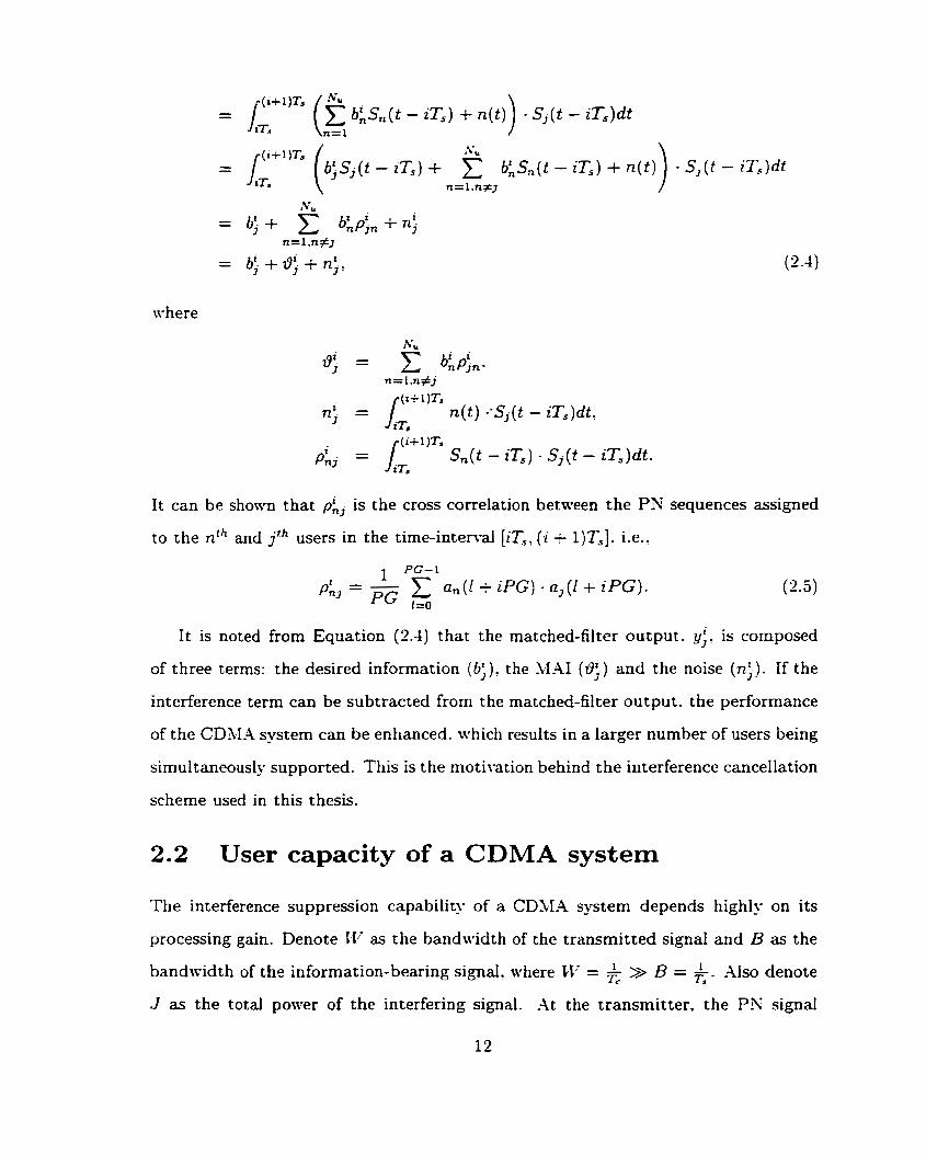
It can be shonn that p L is the cross correlation between the PX sequences assigned
to the nth and j" users in the time-inten-al [iTs, ( 2 + l)Ts]. Le..
t PC-I
It is noted from Equation (2.4) that the matched-filter output. y:' is composed
of three terms: the desired information (b;): the .\LAI (9) and the noise (ni). If the
interference term can be subtracted from the matched-filter output. the performance
of the CDMA system can be enhanced. which results in a larger number of users being
simultaneously supported. This is the motivation behind the interference cancellation
scheme used in this thesis.
2.2 User capacity of a CDMA system
The interference suppression capability of a CDk1.4 system depends highly on its
processing gain. Denote II/' as the bandwidth of the transmitted signal and B as the
bandwidth of the information-bearing signal. where CC; = & » B = &. -Us0 denote
.J as the total ponTer of the interfering signal. .At the transmitter, the PX signal
spreads the information-bearing signal over a wider bandwidth I i.- for transmission.
-At the receiver, the received signal is multiplied with a synchronized replica of the
PX signal to despread the desired signal back to its original bandwidth B and to
spread the interference signal over a nrider bandwidth I.1-. The power spectrum of
the interference signal seen by the receiver has an average power-spectral density of
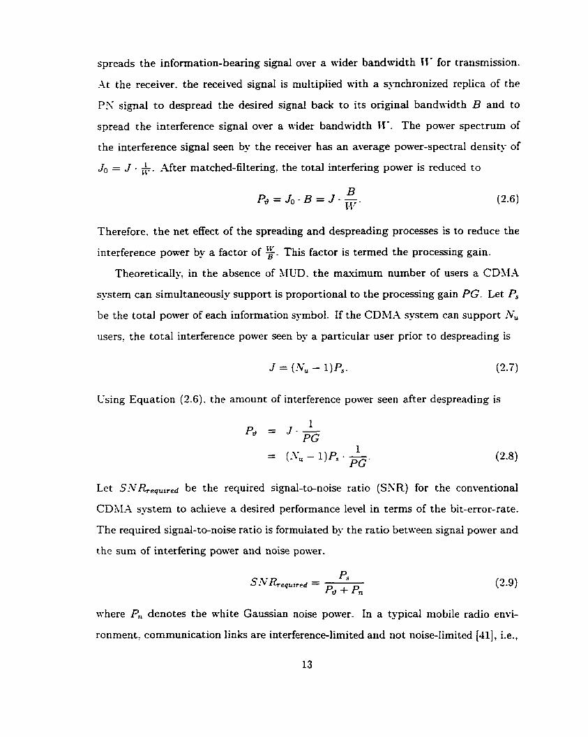
J ~ = J . ' ~ 5 - - After matched-filtering the total interfering power is reduced to
Therefore, the net effect of the spreading and despreading processes is to reduce the
interference power by a factor of g. This factor is termed the processing gain.
Theoretically, in the absence of &IUD. the maximum number of users a CDM-4
system can simultaneously support is proportional to the processing gain PG. Let P,
be the total power of each information symboi. If the CDM-4 system can support ivu
users, the total interference pow-er seen by a particular user prior to despreading is
Esing Equation (2.6). the amount of interference power seen after despreading is
Let SiV&eq,,,,d be the required signal-to-noise ratio (SXR) for the conventionai
CDh.1-A system to achieve a desired performance level in terms of the bit-error-rate.
The required signal-to-noise ratio is formulated by the ratio between signal power and
the surn of interfering power and noise power.
where P, denotes the white Gaussian noise power. In a typical mobile radio envi-
ronment. communication links are interference-limited and not noise-lirnited [41]: i.e.,
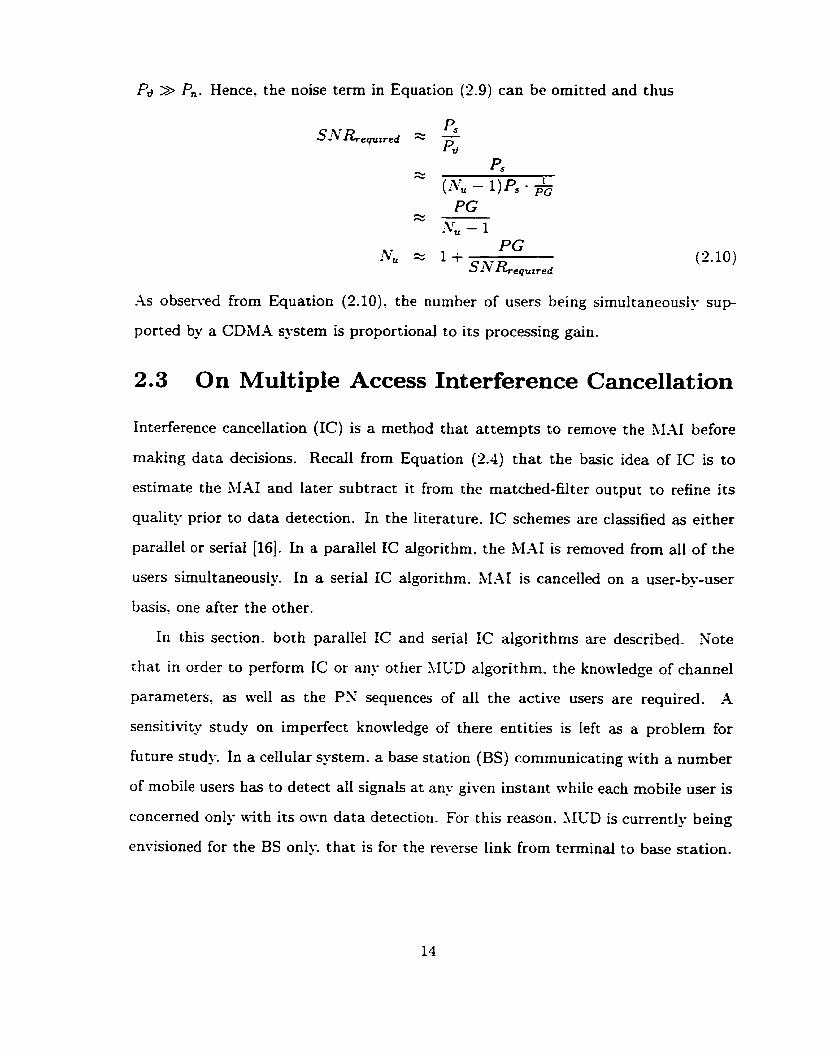
Pd >> P,. Hence. the noise term in Equation (2.9) can be omitted and thus
As observed from Equation (2.10): the number of users being simultaneously s u p
ported by a CDiçZ-4 system is proportional to its processing gain.
2.3 On Multiple Access Int erference Cancellat ion
Interference cancellation (IC) is a method that attempts to remove the hIAI before
making data decisions. Recail from Equation (2.4) that the basic idea of IC is to
estimate the MAI and later subtract it from the matched-filter output t o refine its
quality prior to data detection. In the literature. IC schemes are classified as either
parallel or seriai [16]. In a parallel IC algorithm. the MAI is removed from al1 of the
users simultaneously. In a serial IC algorithm. SIAI is cancelled on a user-by-user
basis. one after the other.
In this section. both parallel IC and serial IC algorithms are described. Note
that in order to perform IC or an' other l I G D algorithm. the knowledge of channel
parameters. as well as the PX sequences of al1 the active users are required. -2
sensitivity study on imperfect knowledge of there entities is left as a problem for
future s t u d . In a cellular system. a base station (BS) communicating with a number
of mobile usen has to detect al1 signals at any given instant while each mobile user is
concerned only a i t h its olr-n data detection. For this reason. hICD is currently being
envisioned for the BS only. that is for the reverse link from terminal to base station.

Figure 2.3: -4 general Nu-user parallel interference cancellation algorithm
2.3.1 Parallel Interference Cancellat ion
In the parallel IC algorithm. the MAI is estimated based on a rough evaluation on al1
users' messages. -4 final decision is made after the estimated M-41 is removed from
the received messages. Figure 2.3 illustrates the parallel IC algorithm.
Let 6; be the ith bit decision made for the jth user. One common way to estimate
received user bit is by the sign of the received amplitude, Le.,
where sgn(-) is a function that returns the sign of the variable in question.
With the knowledge of the cross-correlation values between al1 the P N sequences
and the initial decisions on al1 the users' bits. the MAI can be estimated. Let 8; be
the estimated M.41 seen by the jt" user at the ith syrnbol interval. 8; is estimated as
Let bi be the final decision on 6;. bi is formulated as
b; = q. (Y; - 8;)
= sgn (b; + ni - - 3;)
Su
= sgn (b; +ni + p;(6i -gi) n= 1 ,n#;
Xote chat an incorrect initial bit decision for a particular user doubles its contributed
3.1-41. The parallel IC algorithm improves performance if the initial bits decisions are
relatively reliable.
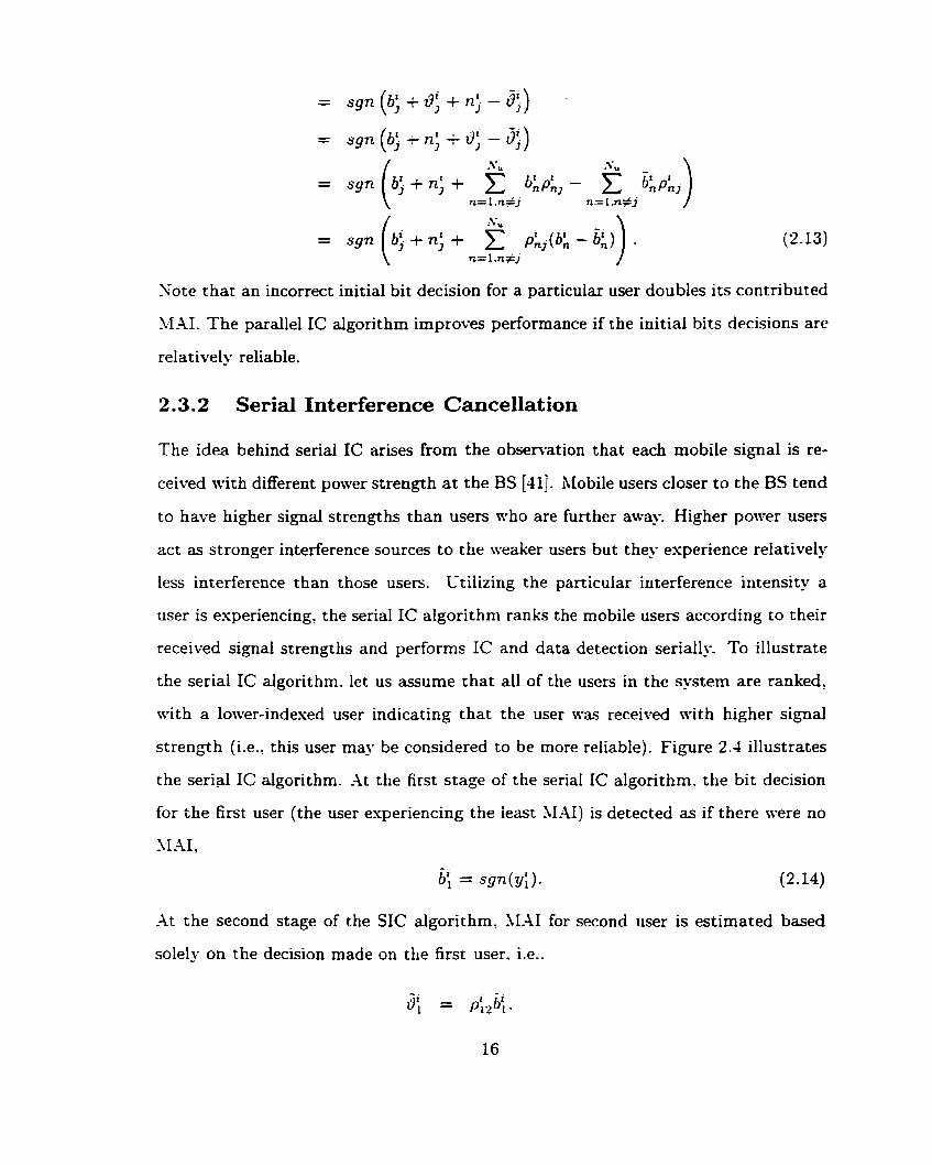
2.3.2 Serial Interference Cancellation
The idea behind serial IC arises from the observation that each mobile signal is re-
ceived n i th different power strength a t the BS (411. hIobile users closer to the BS tend
to have higher signal strengths than users who are further awa . Higher power u s e s
act as stronger interference sources to the weaker users but the' esperience relatively
less interference t han t hose users. Ltilizing the particular iriterference intensity a
user is esperiencing, the serial IC algorithm r a n k the mobile users according to their
received signal strengths and perfonns IC and data detection seriall. To illustrate
the serial IC algorithm. let us assume that al1 of the users in the system are ranked,
with a lower-indesed user indicating that the user \vas received with higher signal
strength (i.e.. this user may be considered to be more reiiable). Figure 2.4 illustrates
the serial IC algorithm. -At the first stage of the seria1 IC algorithm. the bit decision
for the first user (the user esperiencing the ieast 11-41) is detected as if there were no
m r ,
-At the second stage of the SIC algorithm, ,\LAI for second user is estimated based
solely on the decision made on the first user. i.e..

Figure 2.4: -4 general .Vu-user serial interference cancellation algorithm
At the kth stage. the kI-41 for the kth user is estimated based only on the bit decisions
made for the previous k - I users. The final bit decision is made neglecting the
presence of the remaining weaker users.
The above procedure is repeated until al1 of the mobile users are considered.
The serial IC algorithm improves the fidelity of the XL4I estimation at each suc-
cessive stage. Messages sent by the dominant users are detected only using an ap-
proximated M-41 estimation. Messages sent
M,41 are detected using a more refined MAI
Serial IC generally outperforms parallel
by users who suffered severely from the
estimation.
IC in a situation where al1 of the users

are received with different signal strengths. On the other hand. paraIlel IC performs
better when the received signal strengths are relatively equal [29]. For the same
CDk1.4 system, the serial algorithm suffers frorn an estended delay relative ro that
for the parallel algorithm [29]. It is easy to observe that an ,I; bit delay is required for
an ATu-user system with the serial cancellation but only 1 bit delay occurs for systems
\vit h the parallel algorit hm. In practical n-ireless systems. power-control algorithms
are often employed so that al1 mobile users are received with nearly identical signal
strengths at the BS. Therefore. this thesis focuses on a paraIlel IC-based algorithm.
2 -4 Convolut ional Codes
The noise introduced in communication channels corrupts transmit ted signals and
gives rise to channel transmission errors. One way to overcome this problem is to
employ a FEC scheme that adds controlled redundancy to the transrnitted signal.
Such an approach consists of two extra components. At the transmitter side. a channel
encoder is used to add information redundancy. At the receiving side. a decoder is
used to utilize such redundancy to detect and correct channel errors occurred during
transmission. Convolutional coding is one of the powerful FEC techniques that has
been widely used since its invention by Elias [U] in 1955. It is not only used in this
thesis to combat noise introduced by the channel. but it is also used to aid reliable
51-41 estimation for the IC algorithm.
2.4.1 Convolutional Encoder [l, 2, 31
Figure 2.5 demonstrates an encoder with a rate R, of k,/n,: where at each encoding
stage. k, is the number of input bits. n, is the number of output bits, and k, < n,.
The encoder. as a whole, consists of k, parallel shift registers. Each shift register
is composed of r, delay cells. where i denotes the ith shift register and r, may not
equal to r, for i # j. At shift cycle 1. the encoder reads in a binary Ir,-tuple u1 =
{ u ~ ~ ~ . uLJ . - . . Y U ' ~ ~ C - ~ ) and returns an output n-tuple xL = {xi". xLJ ..... X'+C-~} that

ul.I ..-, *S.. m.. I
Figure 2.5: -4 general convolutional encoder of rate-kc/nc
is produced by some Boolean functions operating on the entire set of inputs residing
in the various shift registers. For binaq convolutional codes, these Boolean functions
are modulo-2 sums.
-4s shown in Figure 2.5: the nc output bits are computed not only from the current
k,-tuple entering the encoder but are also computed from al1 other inputs stored
n-ithin the delay cells. Let r-,,, be the maximum number of delay cells of any shift
register. i.e.?
The nc output
T,, kc-tuples.
bits are constrained by the current input kc-tuple and the previous
Define KC as
&= mas r t + l . z=O ...., kc- 1
Hence h', is called the constraint length of the convolutional encoder. -A complete
convolutional encoder is specified by its code rate. constraint length. and its generators
that define the input-output relationship. For example. consider a rate-$_ constraint
length 3. convolutional encoder shown in Figure 2.6. The input-output relationship
is given by two generators. go and gl, that define the connection rules between the
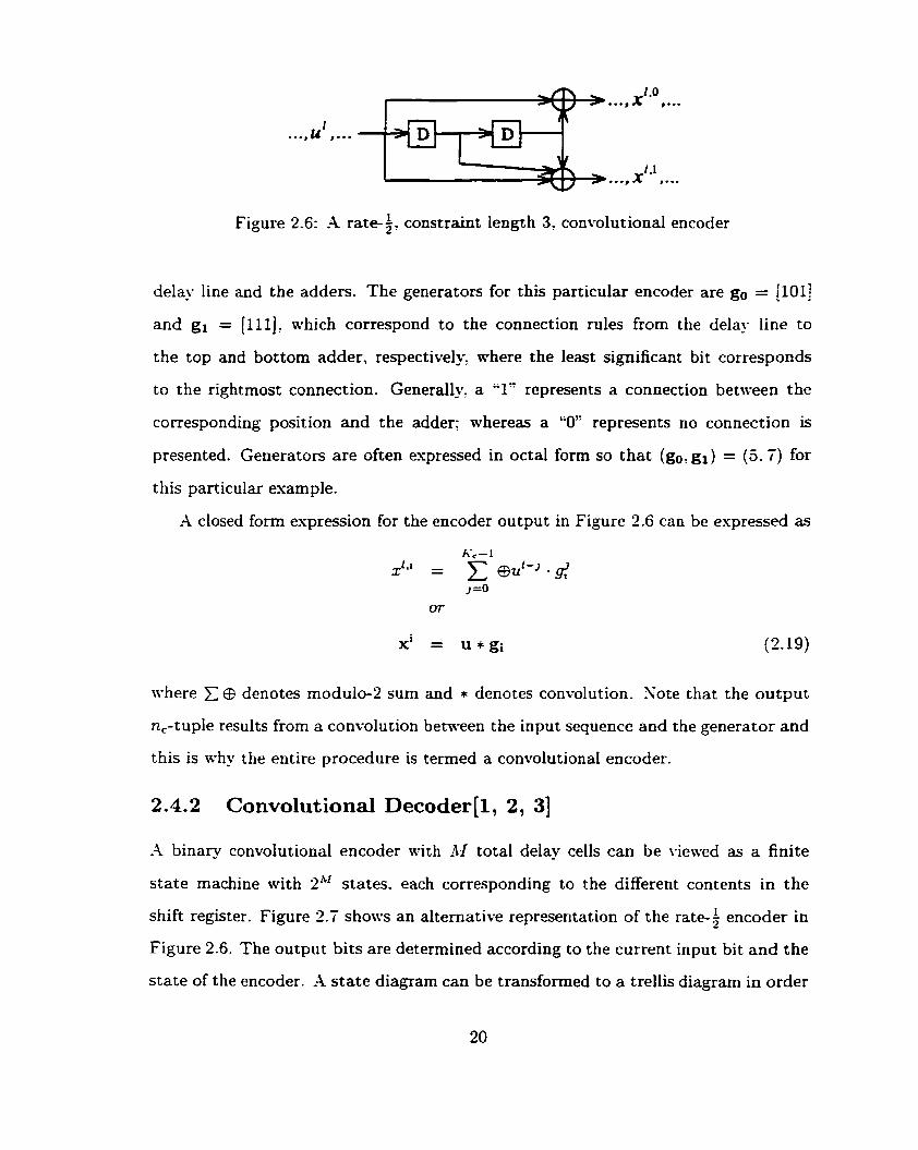
Figure 2.6: -4 rate- $. constraint length 3: convolut ional encoder
delay line and the adders. The generators for this particular encoder are go = [101]
and g, = (1111; ahich correspond to the connection rules from the del- line to
the top and bottom adder, respectively, where the least significant bit corresponds
to the rightmost connection. Generally. a "1" represents a connection between the
corresponding position and the adder; whereas a "O" represents no connection is
presented. Generators are often espressed in octal form so that (go. gl) = (5.7) for
t his particular example.
-4 closed form espression for the encoder output in Figure 2.6 can be espressed as
where >: @ denotes modulo-2 sum and * denotes convolution. Note that the output
n,-tuple results from a convolution between the input sequence and the generator and
this is why the entire procedure is termed a convolutional encoder.
2.4.2 Convolutional Decoder(1, 2 , 31
-4 binary convolutional encoder with LV total delay cells can be viewed as a finite
state machine with 2h' States. each corresponding to the different contents in the
shift register. Figure 2.7 shows an alternative representation of the rate-$ encoder in
Figure 2.6. The output bits are determined according to the current input bit and the
state of the encoder. -1 state diagram can be transformed to a trellis diagram in order

Figure 2.7: State diagram for the rate-& constraint length 3. encoder shown in Figure 2.6
to incorporate time. Figure 2.8 shows the trellis diagram for the encoder in Figure 2.6.
Let Si: i = O?. . . : 2"' - 1, be the ith state of the encoder. It is assumed that the initial
and the ending States of the encoder are at state So, the all-zero state. Each branch
of the trellis diagram is labeled 114th the output bits corresponding to the associated
state transition. Eveq- codeword in a convolutional code is associated with a unique
path starting and ending a t state So through the associated trellis diagram. For a
rate-k,/n, code, there are 2'. branches leaving and entering each node. Giren an
input sequence of k,L bits' there are 2kL distinct paths through the general trellis,
each corresponding to a convolutional codeword of length n,(L t ICc - l), where
rie - 1 is the number of state transitions required for the encoder to return to state
So after the input sequence has been entered into the encoder. Therefore, the optimal
decoding algorithm. the ML decoder. involves searching through each of these 2 ' ~ ~
paths for the most probable sequence.
2.4.3 The Viterbi Algorithm (VA)
The Viterbi Algorithm (LT-4) [43]: named after its inventor, -4.J. Viterbi, is a ML
decoding algorithm that is widely used in practice. Instead of searching through al1
possible paths, the \.:A simplifies the ML decoder through the elimination of the non-
survivor paths a t each tirne instant by branch metric and path metric calculations.

Stae O (00)
Sotc 1 (01)
Satc 2 (10)
Sm= 3 (1 1)
L-2 - L-I L L-1 L-2
Figure 2.8: Trellis diagram for the rate-$, constraint length 3' encoder
The branch metric is a convenient value that represents the likelihood of a particular
branch n-hereas the path metne for a particular state at a particular time instant
represents the likelihood of the best path that originates from the initial state So and
ends at the state in question. The idea of the is to select the branch a t each time
instant for each state that results in a path with the best path metric. The selected
paths are cailed the sunrivors, while the others are called non-sumi\-ors.
For a binary rate-+ code, there are 2 branches leaving and entering each state S*
at each time instant i. Let Sp and SI be the 2 States that the 2 branches are entered
from. Let the branch metric for the transition from state S;'l j = 0. 1' at time 1 - 1
to state Si at time [ be denoted by BAfi-l(S:. Silyl-'). where y'-' is the received
n,-tuple at time instant i - 1. Let the path metric that ends a t state S;' at time
Z - 1 be PM:",. The path metric at time Z that includes the jth cornpeting branch is
calculated by
PM? ( j ) = P M ( - ~ ~ t B M [ - ~ (s:. S, I ~ I - ' ) . (2 -20)
The V-A compares the 2 cornpeting path rnetrics. PM,S' (0) and P1\fI1 (l), and selects
the better one. The non-sun-king path is discarded and the winning path and its
corresponding path metric are stored. This add-compare-select process (see Figure
2.9) is repeated for each state at each time instant until the end of the received
codeword is reached. At that time. the path with the best path metric is the M L

tirne f - f time f
Figure 2.9: The add-compare-select process of the Viterbi -Algorithm
path which represents the decoder output.
The VA can be further modified to make data decisions on the Z t h k,-tuple upon
receiving the (1 + I')th symbol where r is called the decoding depth. Instead of
choosing one h4L path, the path with the best path metric is chosen at each time
instant 1 + l? + 1 for decoding the Ph k,-tuple. It was shown in [30] that choosing
r 3 5Kc gives negligible performance degradation relative to the optimum \'.4 in
terms of the BER-
2.4.4 Interleaving
Alost well-known FEC schemes: inciuding convolutional codes. are not capable of
correcting errors in bursts but only those errors that are statistically independent [l].
However, many practical situations such as communicating over a fading channel,
errors tend to occur in bursts. A particularly important technique that aids the
decoders to correct these errors is interleaving. It re-orders a sequence of bits or
symbols according to some deterministic patterns. Its counterpart. deinterleaving,
maps the re-ordered sequence back into its original order.
Interleaving is often done for the encoded sequence prior to transmission while
deinterleaving is done for the dernodulated sequence prior to decoding. Together, the
interleaving and deinterleaving pair scrambles the error sequences seen at the receiver
and may possibly break down burst errors into nearly independent errors and hence
enhances decoder performance.
&coder R e f d
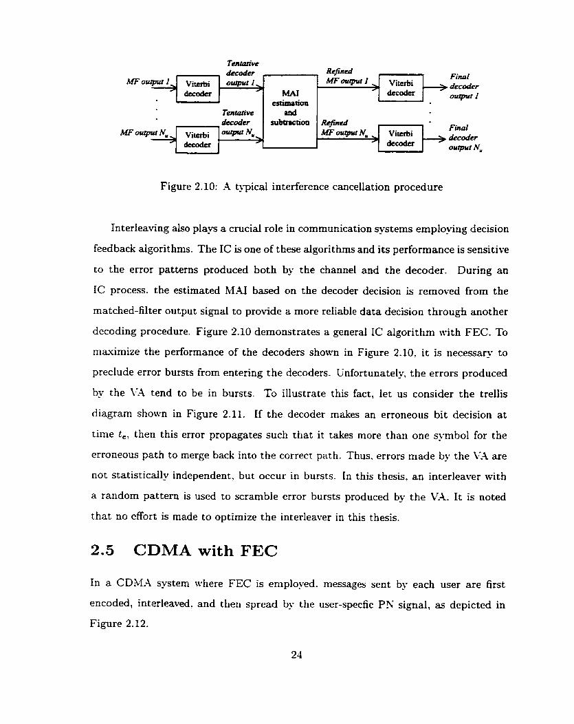
Figure 2.10: -4 typical interference cancellation procedure
Interleaving aiso p lay a crucial role in communication systems employing decision
feedback algorit hms. The IC is one of t hese algorit hms and its performance is sensitive
to the error patterns produced both by the channel and the decoder. During an
IC process. the estimated MAI based on the decoder decision is removed from the
matched-filter output signal to provide a more reliable data decision through another
decoding procedure. Figure 2.10 demonstrates a general IC algorithm with FEC. To
maximize the performance of the decoders shonm in Figure 2.10' it is necessary to
preclude error bursts from entering the decoders. Unfortunately, the errors produced
by the VA tend to be in bursts. To illustrate this fact, let us consider the trellis
diagram s h o w in Figure 2.11. If the decoder makes an erroneous bit decision at
time te' then this error propagates such that it t a h s more than one symbol for the
erroneous path to merge back into the correct path. Thus. errors made by the CA are
not statistically independent. but occur in bursts. In this thesis. an interleaver with
a random pattern is used to scramble error bursts produced by the Val. It is noted
that no effort is made to optirnize the interleaver in this thesis.
& c d v
2.5 CDMA with FEC
, Wou<purI, vitchi decoda
w o u t p u r l
subtnction MFoutpur Nu
In a CDM.4 system where FEC is eniployed. messages sent by each user are first
encoded, intarleaved, and then spread by the user-specfic P': signal. as depicted in
Figure 2.12.
~ O w
, , Final decoder ourpirt l
~~ vi-i
-
R+eà
MAI Vi-i decoder
M F q t N , dec*
0utpvtI
ourp.1 N"
i Final Vitcrbi > decoder

Time Sate O (00)
Smte 1 (O 1)
S u 2 (10)
Sote 3 (1 1)
Figure 2.11: The error propagation diagram for the Viterbi .Ilgorithm
Infomϟon E, Xi souru for > Emod.rjr ) In t . rk ivn j
b, usefj
Figure 2.12:
s,;. 0 )
CDM-4 system with FEC
Figure 2.13: Conventional CD3.l-4 receiver with FEC

Let 2, = [ u; uj . . . u:-' ] be a vector representing the information sequence
sent by the jth user: zj = [ 21: . . - xic-' ] be a wctor representing the encoded
sequence for the j fh user: and !I, = [ b; b; . . . 15:-' ] be a wctor representing the
j th interleaved sequence. where L denotes the length of the information sequence and
L, denotes the length of the encoded sequence. These sequences are related by the
following espressions:
where encode(-) denotes an encoding procedure and Ii(-) denotes interleaving. -At the
receiving end (see Figure 2.13). let y = [ y; . . . -1
] be a vector represent-
ing the matched-filter output sequence for the jth user; let 2, = [ 20 I f . . . ifc-' ] be a vector representing the jth deinterleaved sequence and 3 = [ 6; ûf . . . fifi ] be a vector representing the decoded sequence. These sequences are reiated by:
where ll-'(.) denotes deinterleaving and decode(-) denotes a decoding procedure. -As
in the uncoded case. the ith matched-filter output bit for the jth user? y; ? is formulated
where nf is the noise seen by the j th user during the ith bit interval. is the cross-
correlation between the PX sequences assigned to the jth and the nth users a t the ith
symbol interval, and i = O , . . . ? L, - 1.
The matched-filter output vector for al1 of the users during the ith symbol interval

where R' is an !Vu x Nu cross-correlation matrix.
T b' = [ bf 6; . . . biru ] is a vector representing the ith interkaver output for al1 :V,
users; ni = [ nf n . . . nk lT is a vector representing the zerernean Gaussian
noise with covariance rnatrix given by
where y is the power spectral density of the noise for the .WGN channel.
Equation (2.26) can be rewritten as
where 1% is an Nu x Nu identity matrix and 9' = (Ri - INu)bi denotes the M.41
vector for the ith bit interval. The matched-filter output for a coded CDM4 system
is also composed of three terms: the interleaved encoder output bi; the M.41 di; and
the noise ni. M-41 estimation in a coded system is done through the use of decoder
decisions. The detailed algorithm wil1 be demonstrated in the next chapter.
Chapter 3
The Discrete Mode1
The CDM-4 system model with FEC introduced in the previous chapter (see Figures
2.12 and 2.13) is further simplified for simulation purposes. Instead of generating the
PX sequences for ail of the users. one rnay model the CDBIA system by speci-ing the
cross-correlation matrix Ri shown in Equation (2 .26) . where R is a symmetric matrix
\vit h each element [Ri], representing the cross-correlation between the signature
sequences assigned to the nth and the jth users during the ith bit interval. In the
literature. XWD algorithms are generally studied and analyzed using a symmetric
channel. This channel is often modeled as a R matrix with identical cross-correlation
value between each PX sequence pair. i.e..
where L, is the length of the encoded sequence. This model is referred as the discrete
model in this thesis. -Although the discrete mode1 does not have much relevance in
practice, it does provide a means of rneasurement on the effectiveness of a MUD
algorithm. The typical value of p is about 0.22. The detailed calculation of p is given
in Appendi~ A at the end of this thesis. The rest of this chapter discusses the intuition
behind the different IC methods and presents the performance of each method through
the use of cornputer simulations. These simulations are aimed such that the simulated
BER is within 3~30% of the true BER with 95% confidence. Details on the confidence

MF ovrpwl
a MAI - F i ~ l subboctiori -
decirion 1
MF o u ~ t - MAI > Deciskm
wbbactiori mJgng '
decision N, -
Figure 3.1: -4 general Iterative Interference Cancellation -Ilgorithm
interval and the required number of trials to achieve the desired level of confidence
can be found in -1ppendiu B a t the end of this thesis. The FEC code used is the
rate-$. constraint length 7. convdutional code with generators {13, li}. Based on the
constraint length of the convolutional code. a decision depth of 36 (r 2 5Kc) is used
in the VA for near->IL decoding. To cope mith burst errors produced by each Viterbi
decoder, different block interleavers of size 1000 for each user are also used in the
simulations. These interleavers are randomly generated at run-time and no attempt
is made to optimize them. Since a block structure is needed for the interleavers: the
blocked data of length 2000 synbols that is appended with 36 dummy symbols to
give a block length of 2036 symbols is used in the simulations throughout the thesis.
3.1 Iterative Interference Cancellation
The iterative processing technique has received an enormous amount of attention
since the discovery of Turbo codes [21]. The idea behind an iterative algorithm is to
repeatedly improve the fidelity of the information being sought until no further prac-
tical improvement is attained. Figure 3.1 illustrates the block diagram for a general
iterative interference cancellation (IIC) algorithm. .At each stage of the IIC algorithm,
the MAI is being re-estimated using the decoder decisions from the previous stage of

- k + -hi
ZI =XI -91 ri, -' I * El Zl
Figure 3.2: -4 2-user Iterative Brute Force Interference Cancellation ,LUgorit hm
decoding. -4s the algorithm proceeds, the MU estimate becomes more accurate and
hence improves the quality of the decoded decisions at the end of the IIC aigorithm.
The number of iterations needed to achieve the desired performance level. Le.. the
single-user performance bound, is highly dependent on the channel characteristics
such as the signal-to-noise ratio (SNR) as well as the signal-to-interference ratio. The
criterion for convergence requires reliable decoder decisions at the initial stage.
In the following sections, the algorithms of three different kinds of IL41 cancella-
tion schernes are discussed. The three schemes are brute force cancellation, partial
caiicellation, and sofr cancellation. To demomtrate the capability of these IC tech-
niques, the performance of these schemes on a system with various cross-correlation
values and with different numbers of users are presented. The number of users \vas
chosen so that the simulation results in this Chapter can be cornpared with results in
Chapter 5 of this thesis.
3.1.1 Brute Force Interference Cancellation
In brute force cancellation. an attempt is made for each user to completely remove
the MAI at each stage of the iterating algorithm [16]. Figure 3.2 illustrates the block
diagram for such algorithm on a 2-user system.
Recall from the previous chapter that the matched-filter output sequences of the

2 users are given by:
where y . = [ y: . . . ] denotes the vector representing the j th rnatched- -1
filter output sequence. 9, = [ 9; 19: . . . ] is the wctor representing the j th
MAI sequence and 2, = [ n; nf . . . RF-' ] denotes the vector representing noise
sequence seen by the j th user.
Let the superscript k denotes the kth iteration of the IIC algorithm. Let ü:." be
the tentative decoder decision made a t the kth iteration on the i th information symbol
sent by the jth user. .Also, let 9;' be the estimation made at the kth iteration on the
MAI seen at the ith bit interval by the jch user. The >,LAI seen by the first and the
second user are estimated as
-k = p II (encode@:)) . (3-4)
-k = p - n (encode@:)) . (3.5)
- k where ej = Q?.* d i s k [ 1 I - - - dLc-l" ] denotes the M-AI sequence estimated a t the kih 1
-L-1,k iteration for the jth user‘iif = [ 69' citk . . . 111 ] denotes the j th information
sequence decoded at the kth iteration. Ii(-) denotes an interleaving procedure and
encode(-) denotes an encoding procedure.
At the (k + l)th iteration. the jch matched-filter output sequence is refined by
subtracting the h4.41. 3:' estirnated based on the decoder decisions frorn the previous
iteration:
-k - y1 -21, iktl - - 1 (3-6)
-k - y 2 - 4 - ykfl - -2 (3. '7)
The refined sequence. i jki '. is then deinterleaved and decoded to produce a new -3
decision sequence, ii?":
-"l = decode (Il-' (zjti')). gr -
31
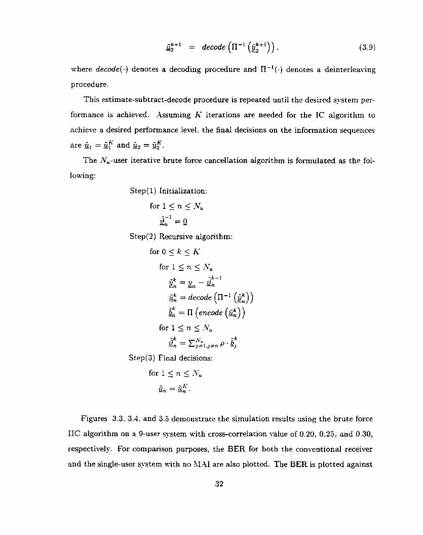
where decode(-) denotes a decoding procedure and n-'(.) denotes a deinterleaving
procedure.
This estimate-subtract-decode procedure is repeated until the desired system per-
formance is achieved. Assuming h' iterations are needed for the IC algorithm to
achieve a desired performance level, the final decisions on the information sequences
The Nu-user iterative brute force cancellation algorithm is formulated as the foi-
Step(1) Initialization:
S tep(2) Recursive algorit hm:
S tep(3) Final decisions:
Figures 3.3. 3.4. and 3.5 demonstrate the simulation results using the brute force
IIC algorithm on a 9-user system with cross-correlation value of 0.20, 0.25: and 0.30,
respectively For comparison purposes, the BER for both the conventional receiver
and the single-user s ~ s t e m with no 31.41 are also plotted. The BER is plotted against

Figure 3.3: Performance of the Brute Force IIC -ilgorithm on a 9-user systern with cross-correlation p = 0.20
+ 4 rteralions
2 2.5 3 3.5 4 4 -5 S SNR (dB)
Figure 3.4: Performance of the Brute Force IIC -4Igorithrn on a 9-user system with cross-correlation p = 0.23

-- 2 3 3 5 4 4 5 5 SNR (dB)
Figure 3.5: Performance of the Brute Force IIC Algorithm on a 9-user system with cross-correlation p = 0.30
the SNR. which is defined as the signal energ'- per information bits. Eh. dil-ided
by No, where 9 is the power spectral density of the noise for the ;\CIGX channel.
This definition of SSR is used on al1 future plots in this thesis. For a particular
plot, the performance of the iterative algorit hm converges rapidly to the single-user
performance bound at the high-SNR region. .At the low-SXR region. the algorithm
converges either with many iterations or it does not converge at ali. Figure 3.5
shows that the operating SKR has to be above a threshold value in order to obtain
performance gain through the use of the cancellation algorithm. The IIC algorithm
converges to the single-user performance bound only at an SNR above the threshold.
Mrhen operating at an SNR below the threshold? no performance gain can be obtained.
Comparing the three figures, increasing the cross-correlation value requires a Iarger
number of iterations for the algorithm to converge to the single-user bound. The
threshold SNR value is also increased as the cross-correlation value increased.
The effect of increasing the nurnber of users is shown through Figures 3.6 to 3.8.
SNR (dB)
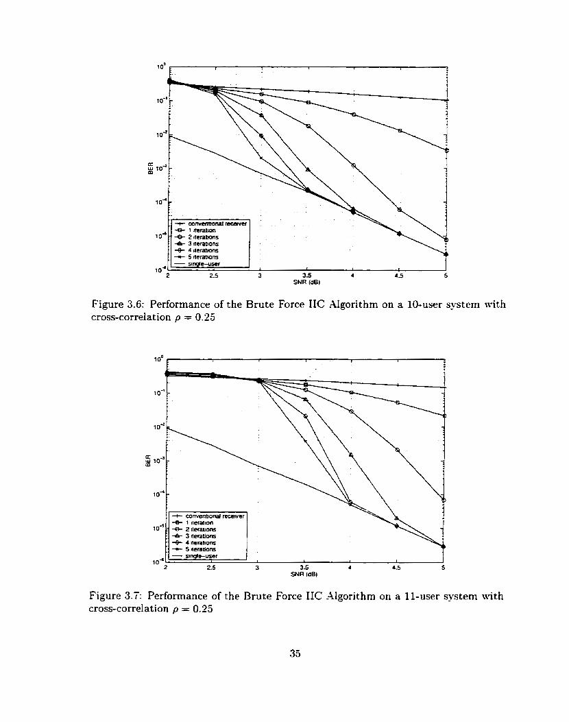
Figure 3.6: Performance of the Brute Force IIC Algorithm on a 10-user s p t e m with cross-correlation p = 0.25
, + convenbonal rccscver
: 6 3 iteraùons + 4 iterabons . + 5 itembons - ungie-user
I I 1
25 3 3.5 4 625 5 SNR (dB)
Figure 3.7: Performance of the Brute Force IIC -4lgorithm on a Il-user system with cross-correlation p = 0.23
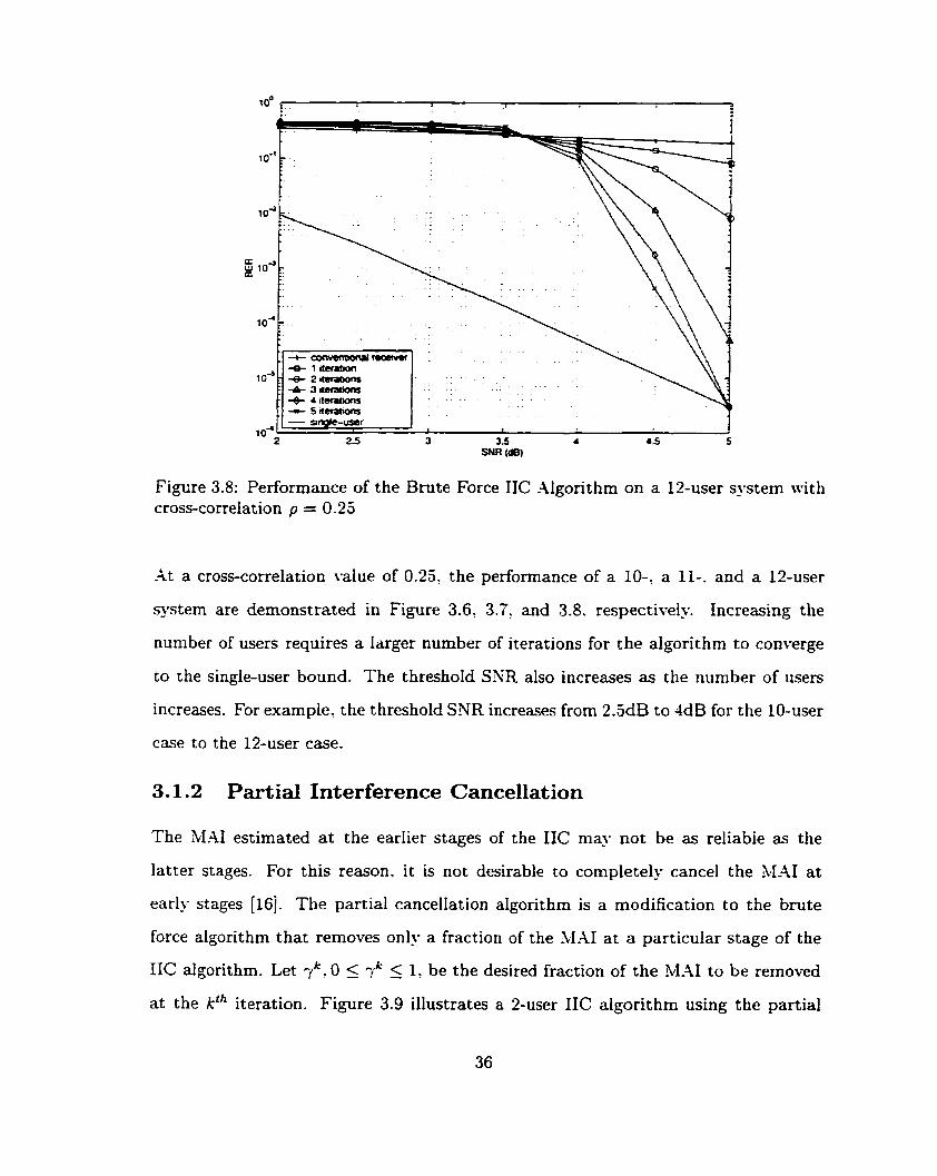
Figure 3.8: Performance of the Brute Force IIC -4lgorithm on a 13-user sxstem with cross-correlation p = 0.23
-kt a cross-correlation value of 0.25, the performance of a IO-: a II-. and a 12-user
system are demonstrated in Figure 3.6, 3.7: and 3.8. respectively. Increasing the
number of users requires a larger number of iterations for the aigorithm to converge
to the single-user bound. The threshold SNR also increases as the number of users
increases. For example. the threshold SNR increases from 2.5dB to 4dB for the 10-user
case to the 12-user case.
3.1.2 Partial Interference Cancellation
The M.41 estimated a t the earIier stages of the IIC may not be as reliabie as the
latter stages. For this reason. it is not desirable to completely cancel the hl-41 at
early stages [16]. The partial cancellation algorithm is a modification to the brute
force algorithm that removes only a fraction of the hl-AI at a particular stage of the
IIC algorithm. Let 0 5 T' 5 1, be the desired fraction of the MAI to be removed
at the kth iteration. Figure 3.9 illustrates a 2-user IIC algorithm using the partial

Figure 3.9: -4 2-user Partid Iterative Interference Cancellation -Aigorithm
cancellation algorithm. The structure of the partial-IIC algorithm is almost identical
to the brute force case except for the M-41 estimation in Equations (3.4) and (3.5) are
The :Vu-user iterative partial cancellation algorithm is formulated as follow:
S tep(1) Initialization:
for 1 5 n 5 -Yu
a-' = 0 -n - S t ep (2) Recursive algorit,hrn:
for O 5 k 5 h'
Y; = decode (II-' (6")) -n
-k b, = l2 (encode (ci))
for 15 n 5 .rV,
sk = -,k =-y" -k -n j=i.j+n P - bj
S tep(3) Final decisions:

Figure system
3.10: with
t
5 toa: m .
los:--- c o m n O ~ - l ~ l + @am
1 +- . 4 a= a - * f) @- - eniuFora(@i=)
Cornparison on different values of the cancellation fractions cross-correlation p = 0.25
Figure 3.10 compares the performance of a 1-iteration partial cancellation algo-
rithm using different cancellation fractions on a 9-user system with cross-correlation
p = 0.25. NÏhen cancellation fraction. il. is above 50%. the partial cancellation algo-
rithm outperforms the brute force cancellation a!gorithm in the case shown. IVhen
the fraction is belon. 50%. the performance gain is obtained only at the low-SNR
region. For al1 SSR values. the fractions with values above 50% are superior than
those below 50%. Sotice that when the initial decoder decisions are relatively re-
liable, a larger cancellation fraction. i.e. = 80%. gives more performance gain
than the smaller one. Le.. = 60%. IVhen the initial BER is not reliable, a smaller
cancellation fraction. i.e. = 60%. results in better performance.
Figure 3.11 shows the performance of the partial IIC algorithm on a 9-user CDlc.1-4
system with cross-correlation p = 0.30. The cancellation fractions are 60% for the
first iteration 100% for the remaining iterations. Comparing to the brute force case
shomn in Figure 3.5. removing a fraction of the hIAI at only the first iteration signifi-
cantly enhances the performance of the IIC algorithm. The system employing partial

SNR (a)
Figure 3.11: Performance of Partial IIC Algorithm with cancellation fraction 7' = 60% on a 9-user system with cross-correlation p = 0.30
cancellation at iteration one iowered the threshold SNR value frorn about 3.75dB to
about 2.5dE3.
It is also possible to further improve the performance at the low-SNR region by
employing partial cancellation for more than 1 iteration. Figure 3.12 demonstrates the
performance of using partial cancellation for the first 4 iterations. The cancellation
fractions are 7' = 50%. î2 = 50%. 7 d 3 = 60%. 74 = 60%. respectiwly. Comparing
Figure 3.11 and 3.11. the 4-iteration partial IIC algorit hm significantly decreases the
threshold SKR and enhances the performance for the low-SXR region, but it does
not perform as well as the single-iteration case for the high-SNR region. -At higher
SNR, a relatively large canceilation fraction is required to obtain improvement over
the brute force algorithm. Whereas at lower-SXR. a smalIer fraction results in better
performance. Therefore. one should select these cancellation fractions according to
the desired operating S-iR. For operating at high-SNR. employing partial cancellation
a t only the first iteration wouid be sufficient to enhance system performance. For

- ungit-uscr 1 1 1 I 1
2 25 3 3.5 4 4.5 5 SNR (dB)
Figure 3.12: Performance of Partial IIC Algorithm with cancellation fractions -y1 = 5O%, y2 = 50%: -y3 = 60% and -t4 = 60% on a 9-user -tem with cross-correlation p = 0.30
operating at low-SNR region. several iterations of partial IC are required instead. The
optimal choice of these cancellation fractions depends highly on the system parameters
such as the number of users. the cross-correlation values. and the SSR. Yo effort is
made in this thesis to optimize these cancellation fractions.
3.1.3 Soft Interference Cancellation
The idea behind soft interference cancellation originates from partial interference
cancellation. During each symbol intemal. the decoded symbol of some users ma?; be
more accurate than others. Therefore. it is not optimal to use the same cancellation
fraction for al1 of the users. instead. cancellation can be done based on a reliability
rneasure for each decoded symbol of each user at each stage. This reliability measure
can be obtained by modifying the l ï te rb i algorithm.
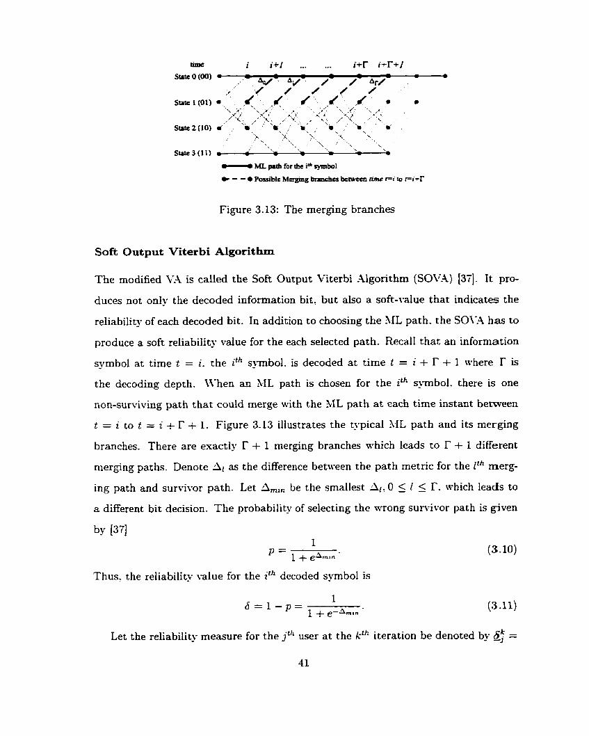
ML p.th for tbe iOL symbol
Figure 3.13: The merging branches
Soft Output Viterbi Algorithm
The modified V-4 is called the Soft Output Viterbi Algorithm (SOV-4) [37]. It pro-
duces not only the decoded information bit, but also a soft-value that indicates the
reliability of each decoded bit. In addition to choosing the path. the S0\-.4 h a to
produce a soft reliability value for the each selected path. Recall that an information
symbol at time t = 2 . the ith s ~ m b o l . is decoded a t time t = i + r + 1 where r is
the decoding depth. Mhen an ML path is chosen for the ith symbol, there is one
non-sunriving path rhat could merge with the ML path at each time instant between
t = i to t = i + I' + 1. Figure 3.13 illustrates the typical M L path and its merging
branches. There are exactly r + 1 merging branches which leads to r + 1 different
merging paths. Denote Ar as the difference between the path metric for the Ph merg-
ing path and survivor path. Let Amin be the smallest 0 5 1 5 i'. which leads to
a different bit decision. The probability of selecting the wrong survit-or path is given
Thus- the reliability value for the ith decoded symbol is
Let the reliability measure for the jch user a t the kch iteration be denoted by 6: =
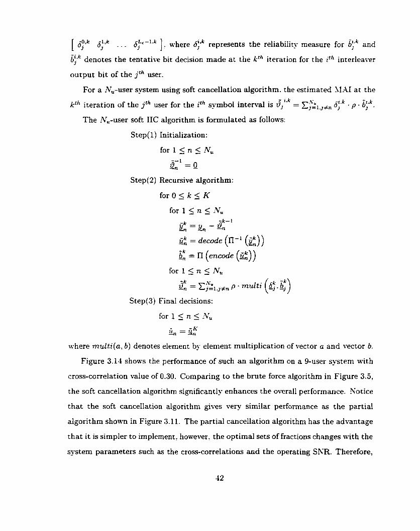
[ #?Y* 6;qk 6Lc-l .k 3 ... I 1: where b ; l k represents the reliability rneasure for &;* and
h;lk denotes the tentative bit decision made a t the kth iteration for the ith interleaver
output bit of the jth user.
For a Nu-user system using soft cancellation algorithm. the estimated IIAI at the
6'2.k Ph iteration of the jth user for the ith symbol interval is 6jiVk = x;kLJÉn - t k - p - 6 ; .
The Nu-user soft IIC algorithm is fomulated as follows:
S tep(1) Initialization:
for 1 5 n 5 -rV,
8-L = 0 -n -
Step(2) Recursive algorithm:
where multi(a, 6) denotes element by element multiplication of vector a and vector 6 .
Figure 3.14 shows the performance of such an algorithm on a 9-user system with
cross-correlation value of 0.30. Comparing to the brute force algorithm in Figure 3.5,
the soft cancellation algorithm significantly enhances the overall performance. Yotice
that the soft cancellation algorithm gives very similar performance as the partial
algorithm shown in Figure 3.1 1. The partial cancellation aigorithm has the advantage
that it is simpler to impiement. hotvevert the optimal sets of fractions changes with the
system parameters such as the cross-correlations and the operat ing SNR. Therefore,
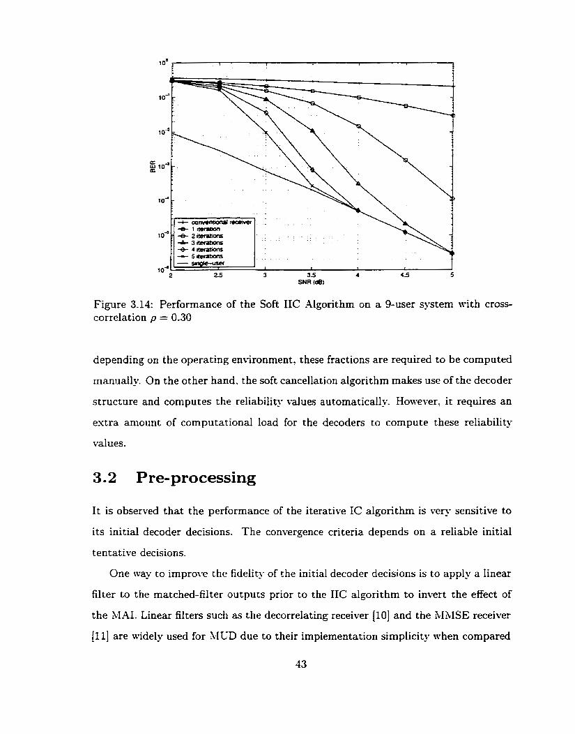
Figure 3.14: Performance of the Soft IIC Algorithm on a 9-user system with cross- correlation p = 0.30
depending on the operating environment. these fractions are required to be computed
manually. On the other hand. the soft cancellation algorithm makes use of the decoder
structure and cornputes the reliability values automatically. However. ic requires an
extra amount of computational load for the decoders to compute these reliability
values.
It is observed that the performance of the iterative IC algorithm is very sensitive to
its initial decoder decisions. The convergence criteria depends on a reliable initial
tentative decisions.
One way to irnpro1.e the fidelity of the initial decoder decisions is to apply a Iinear
filter to the matched-filter outputs prior to the IIC algorithm to invert the effect of
the MAI. Linear filters such as the decorrelating receiwr (101 and the MUSE receiver
[Il] are widely used for XKD due to their implementation simplicity when compared
to the optimal MUD algorithm [il. They can be used in association a-ith the IIC
algorit hrns for furt her performance enhancement.
3.2.1 The Decorrelating detector
The decorrelating detector is one of the early MUD algorithms proposed [IO]. It
cancels the effect of MAI by decorrelating the matched-filter outputs. To demon-
strate the intuition behind the decorrelating detector, let us first consider a noise-free
environment. Recdl from Equation (2.26) that the matched-filter output vector is
where at the ith bit interval, R is the cross-correlation mat*, b' is the message vector
and ni is the noise vector.
In the absence of noise, the matched-filter output vector is simplified to
y' = Rbi
= bi+ (R- rNU)bi
= bi+9':
nhere IN, is a Nu x iK identity matrix, 19' is the M-41 vector, Nu is the number of
users, and i denotes the ith bit interval.
When the conventional receiver is employed, detection error occurs due to the
presence of the 34-41? 9'. To remove the effect of the MAI, the matched-filter output
vector y' is processed by rnultiplying it with the inverse of cross-correlation rnatrix
prior to data detection. Let z' be the resulting output vector,
where R-' is the inverse of R. If the cross-correlation matrui R is invertible, then
the decorrelating receiver exists, and hence the MAI can be successfully eliminated.
In the presence of noise. the processed matched-filter output can be espressed as
-4s observed from Equation (3.15)? the processed matched-filter output has only two
terms: the desired message vector b' and the noise vector R%'. The hIAI is com-
pletely eliminated by the decorrelating detector, however. the embedded noise. R-LnL.
is also enhanced [7]: which degrades the performance of the decorrelating detector rel-
ative to the optimal multi-user detector.
3.2.2 The Minimum Mean-Squared-Error Detector
The MMSE detector is another linear MUD algorithm proposed in the literarure [Il].
C'nlike the decorrelating detector. the MMSE detector takes into account the effect
of channel noise and gives appropriate tradeoff between AL41 rejection and noise
enhancement. The MIISE detector M. rninimizes the mean-squared error between
the matched-filter output and the resulting output zz. Its complete derivation can
be found in [î]. The MMSE detector is formulated as
where is the power spectral density of the noise for the .4M7GK channel. and IN,
is an iV, x !Vu Identity matris.
The MMSE detector M does not require the cross-correlation matris R to be
non-singular. It is also shown in [7] that the MMSE detector always e'ust.
3.2.3 Iterative Interference Cancellation with Pre-processor
Linear filtering can be applied to the matched-filter outputs prior to the IIC algo-
rithrns to aid reliable initial decoder decisions for accelerating the convergence rate

Figure 3.15: Performance of the decorrelating detector and XIPI4SE detector on a 9-user systern wit h cross-correlation p = 0.25
of the iterative IC aIgorithms. The use of a linear filter is referred to as the "pre-
processor" in this thesis.
Figure 3.15 compares the performance of the conventional receiver, the decorre-
Iating detector, and the 313ISE detector on a 9-user systern with cross-correlation
p = 0.25. The performance of the decorrelating detector and the hlMSE detector are
very sirnilar. Both detectors improve the BER by a significant amount when com-
pared to the conventional receiver. The performance of the decorrelating detector is
slightly better than the MMSE detector in the case shown. It is also less comples
to implement since it requires no knowledge about the channel noise. Therefore, the
decorrelating detector is always employed as the pre-processor in this thesis if it ex-
ists. Othenvise. the LIAISE detector is employed. In the cornputational results in
this Chapter, the decorrelating detector is always used as the pre-processor.
Let G be the pre-processor to be applied prior to the IIC algorithm. The pre-
processor-aided brute force IIC algorithm is formulated as follows:
Step(1) The initial stage:
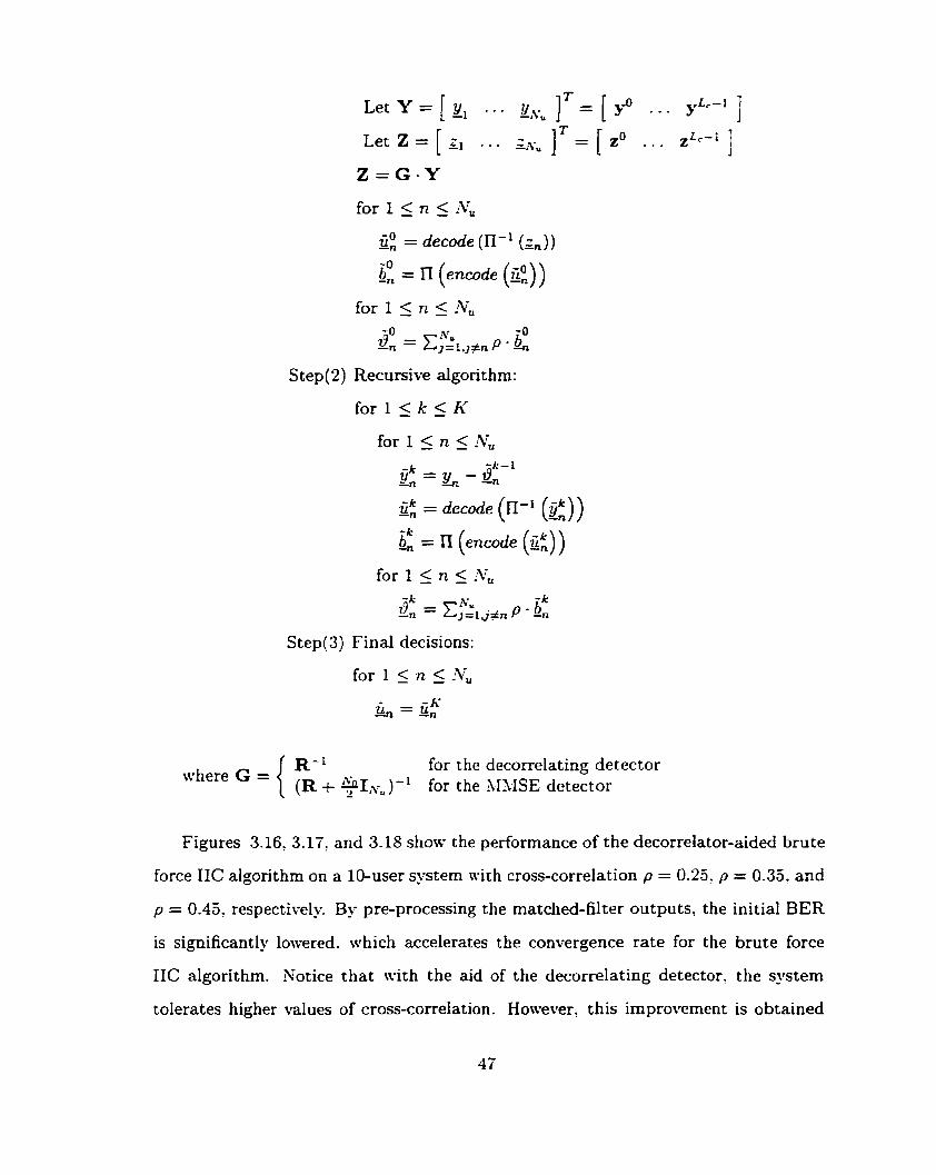
for 1 5 n 5 ATu
2: = decode (II-' (gn))
S tep(2) Recursive algorithrn:
for 1s k 5 h'
for I 5 n 5 ATu
Step(3) Final decisions:
for the decorrelating detector where G = { 1 ) for the \,IMÇE detector
Figures 3.16, 3.17, and 3.18 show the performance of the decorrelator-aided brute
force IIC algorithm on a 10-user system mith cross-correlation p = 0.25. p = 0.35. and
p = 0.45, respectively. By pre-processing the matched-filter outputs, the initial BER
is significantly lowered. which accelerates the convergence rate for the brute force
IIC algorithm. Notice that with the aid of the decorrelating detector, the system
toIerates higher values of cross-correlation. However! t his improvement is obtained

Figure 3.16: Performance of the pre-processor-aided Brute Force IIC Xlgorithm on a 10-user system with cross-correlation p = 0.25
Figure 3.17: Performance of the pre-processor-aided Brute Force IIC Algorithm on a 10-user system with cross-correlation p = 0.35
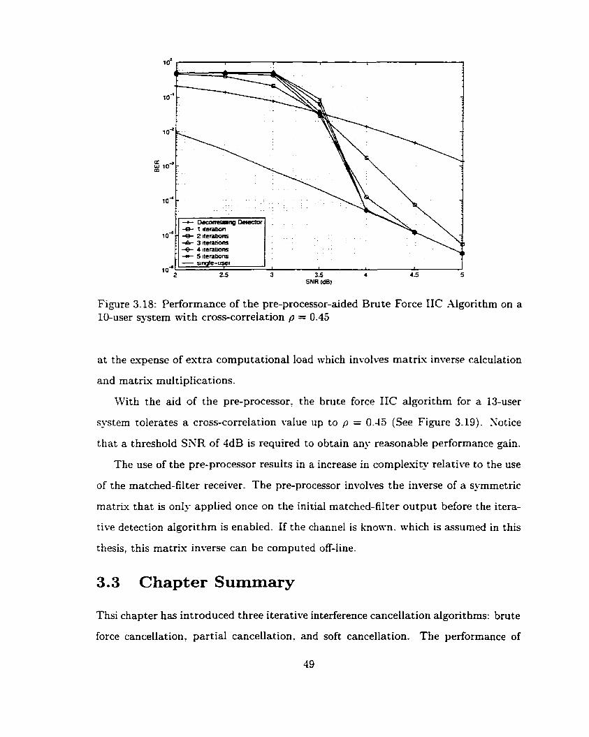
SNR (dB)
Figure 3-18: Performance of the pre-processor-aided Brute Force IIC -ilgorit hm on a 10-user system tvith cross-correiation p = 0.45
a t the expense of extra computational load which involves matrix inverse calculation
and matrix multiplications.
With the aid of the pre-processor, the brute force IIC algorithm for a 13-user
system tolerates a cross-correlation value up to p = 0.45 (See Figure 3.19). Xotice
that a threshold SXR of 4dB is required to obtain any reasonable performance gain.
The use of the pre-processor results in a increase in complexity relative to the use
of the matched-filter receiver. The pre-processor in\*olves the inverse of a symmetric
mat ri^ that is only applied once on the initial rnatched-filter output before the itera-
tive detection algorithm is enabled. If the channel is knom-n. which is assumed in this
thesis, this matris inverse can be computed off-line.
Chapter Summary
Thsi chapter has introduced three iterative interference cancellation algorithms: brute
force cancellation, partial can~el la t ion~ and soft cancellation. The performance of
Figure 3.19: Performance of the pre-processor-aided Brute Force IIC -Algorithm on a 13-user system with cross-correlation p = 0.45
these algonthms are demonstrated and cornpared through the use of computer sim-
ulat ions. The brute force cancellation algorit hm seeks to corn plet el?. eliminates 31-41
at each iteration mithout taking into account the reliability of M.41 estimation. The
partial cancellation algorithm rnakes use of the reliability property of the iterative
algorithm and removes only a portion of the M-41 according to user-defined cancel-
lation fractions. The soft cancellation scheme uses the reliability measure provided
by the soft output Viterbi decoder and performs cancellation accordingly In general,
the soft cancellation scheme gives the best performance among the t hree algorithms.
It has the lowest threshold SXR. but it is also the most complex algorithm to im-
plement. The partial algorithm is less complex compared to the soft algorithni, but
i t gives similar performance to the soft algorithm a t high-SNRs. The brute force
algorithm has the worst performance arnong the three algorithms. It has the highest
t hreshold SNR and the slowest convergence rate.
The pre-processor-aided IIC algorithm is also introduced in this chapter. The two

pre-processors discussed are the decorrelating detector and the MNSE detector. \Vit h
the aid of a pre-processor. each IIC algorithm can support more users and tolerate a
higher cross-correlation value. In particular. a 13-user system using the pre-processor-
aided brute force IIC scheme can tolerate a cross-correlation value up to 0.45. The
improvement in performance is obtained at the expense of increased computational
complexity. which invoives matrix inversion and matrix multiplications.
Chapter 4
The Signature Sequences
The mathematical properties of the signature sequences used in CDhL4 communi-
cations are of fundamental importance in deterrnining the characteristics of such a
system. Recall from Equation (2.4) that when despreading is applied to the received
si,snaI, the arnount of the 34-11 contributed depends on the cross-correlation proper-
ties of the signature sequences. Good performance of such a system requires signature
sequences to have low cross-correlation values. Ideally, spreading codes are infinite
random sequences of equally likely binary digits. Ijnfortunately, the infinite memory
storage requiremeiit in both transmitter and receiver prohibits the use of such se-
quences, Therefore, mat hemat ically-generated periodic sequences t hat nearly satisfy
the randomness properties are generally employed [3 1). These sequences are called
the P N sequences. The randomness properties defined in Cooper and b1cGillem [32]
are re-stated as follo~vs:
1. In every period, the number of positive ones differs from the nurnber of negative
ones by exactly one. Hence the period A* is an odd number.
2. In e v e l period. half of the runs of the same sign have length 1. one fourth have
Iength 2, one eighth have length 3. and so forth. Also the number of positive
runs equals the number of negative runs.
3. The autocorrelation of a periodic sequence is tw-valued. That is, it can be
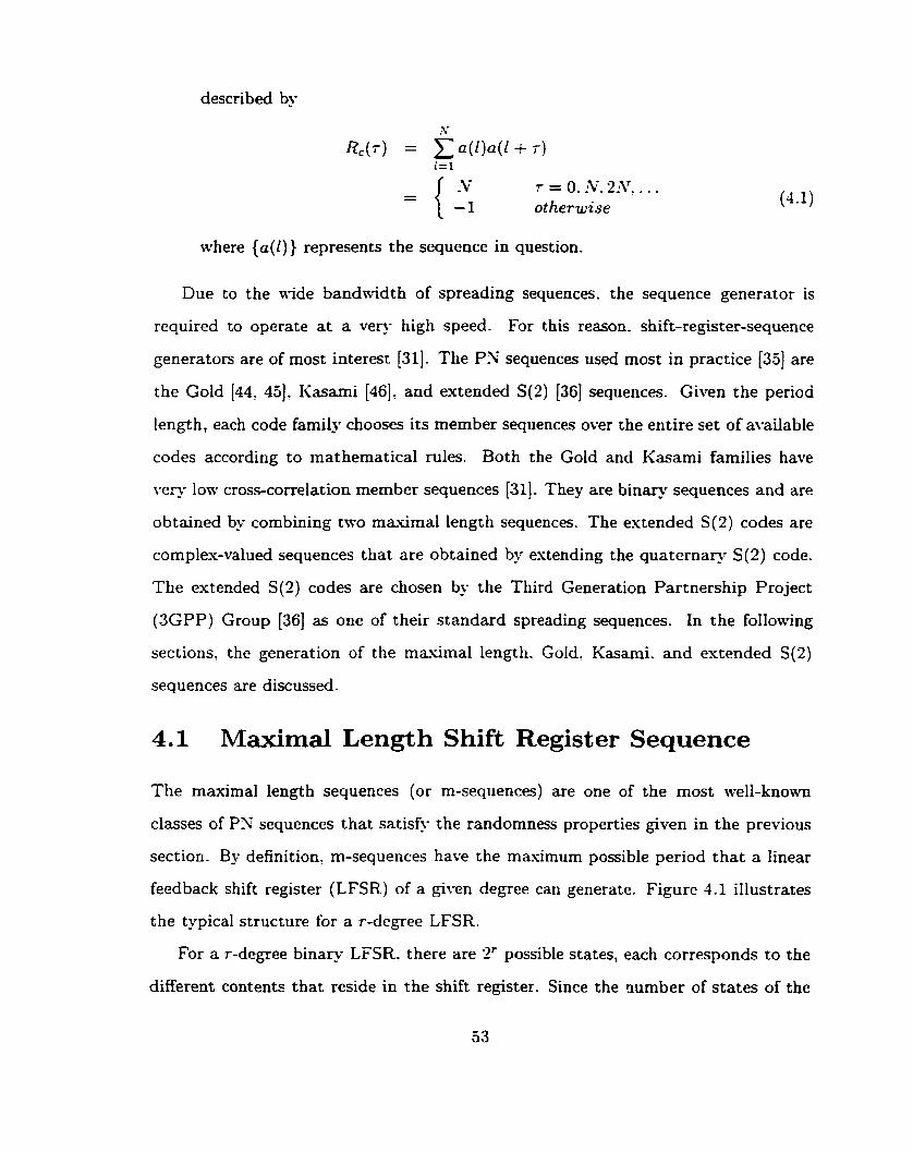
described by
7 = O. iv, 2 ~ ~ ~ . . . otherwise
where { a ( l ) ) represents the sequence in question.
Due to the nlde bandwidth of spreading sequences. the sequence generator is
required to operate at a veq- high speed. For this reason. shift-register-sequence
generatow are of most interest [31]. The PX sequences used most in practice (333 are
the Gold 144, 453. Kasami [46] and extended S(2) (361 sequences. Given the period
length, each code family chooses its member sequences over the entire set of available
codes according to mathematical d e s . Both the Gold and Kasami families have
very low cross-correlation member sequences [31]. They are binary sequences and are
obtained by combining two maximal length sequences. The estended S(2) codes are
complex-valued sequences that are obtained by estending the quaternaq S(2) code.
The extended S(2) codes are chosen by the Third Generation Partnership Project
(3GPP) Group [36] as one of their standard spreading sequences. In the folloaing
sections, the generation of the masimal length. Gold, Kasami. and estended S(2)
sequences are discussed.
4.1 Maximal Length Shift Register Sequence
The maximal length sequences (or m-sequences) are one of the most well-known
classes of P N sequences that satisfj- the randornness properties given in the previous
section. By definition. m-sequences have the masimum possible period that a Iinear
feedback shift register (LFSR) of a @\-en degree can generate. Figure 4.1 illustrates
the typical structure for a r-degree LFSR.
For a r-degree binary LFSR. there are 2' possible states, each corresponds to the
different contents that reside in the shift register. Since the riumber of states of the

Figure 4.1: The structure for a r-degree Linear Feedback Shift Register
LFSR is finite, the LFSR sequences are periodic 1331. To generate sequences with the
maximum possible period, the LFSR cycles through every possible state escept for
the all-zero state. as the subsequent states of the dl-zero state is always the all-zero
state. Therefore the maximum possible period .V for a r-degree LFSR is - 1 since
there are only 2' - I non-zero shift registers states.
Let {g17.. . ,g,},gi E {O. l}: 1 5 i 5 r, be the binary feedback coefficients of the
LFSR as s h o m in Figure 4.1. At each clock cycle, the LFSR shifts al1 contents to the
right and cornputes the feedback input. ai. The sequence { a * } is generated according
to the recursive formula
where gk, at E {O, 1}: 1 5 k 5 r and & denotes modulo-2 sum.
Define the output function of the LFSR as G(D),
where D is the delay operator. G ( D ) is called the generating polynomial of the shift
registers sequence. Combining Equations (4.2) and (4.3), the generating polynomial
becomes
Equation (4.4) gives:
where go(D) = zLz1 e9kDka-iD-' + . . . + a-lD-i and f (D) = 1 + EL,, @gkDk.
Therefore, the infinite generating polynomial G ( D ) can be espressed as a ratio of two
finite polynomials go(D) and f (D) . The denominator polynomial go(D) is dependent
on the initial load {a - , . . . . a- 1 } of the shift registers sh i ch determines the phase shift
of the sequence {a,}. The numerator polynomiai f ( D ) in Equation (4.5) is called the
characteristic polynomial for the LFSR sequence. This polynomial determines the
characteristics of the sequence {ai} such as the period length.
To generate an m-sequence. the characteristic polynomial f (D) of the LFSR must
be primitive. A polynomial of degree r is primitive if the following two conditions are
satisfied:
1. The smallest integer n for which f (D) divides Dn + 1 is n = 2' - 1 = N, and
2. f (D) is irreducible (non-factorable). i.e.. f ( D ) # f l ( D ) - f i (D) .

Figure 4.2: -4 %stage m-sequence generator
Table 4.1: A list of m-sequences generated using primitive polynomial f (D) = 1 +
.\nother restriction on generating m-sequences is that the initial state of the LFSR
D + D 2
has to be non-zero since a all-zero initial state generates only the all-zero sequence.
I n i t i a l l ~ a d { a - ~ , a - ~ ) { O : 11
Primitive polynomials exist for al1 values of the degree of the generating polpo-
mial T, r > 1. It is also showm in [33] that the number of primitive polynomials of
Statestransitions O 1 + 10 + 11 + O 1 + . . .
degree r is equal to
(ai 1 1~01l0110. - .
where {Pi, i = 1.2. . . - . k} is the prime decomposition of 2' - 1. That is.
where ni is an integer. -4 complete list of primitive polynomials with degree r 5 34
can be found in Peterson and Weldon [34].
Figure 4.2 illustrates a fi-stage m-sequence generater with primitive polynomial
f ( D ) = 1 + D + D2. The sequence { a i } is periodic with period N = 3. Table 4.1
lists the different m-sequences generated using the LFSR in Figure 4.2 with different
initial loads. The state transitions of each sequence are also shown in Table 4.1.
As observed from Table 4.1, using different initial loads resulted only with a
different phase shift of the same m-sequence. Without loss of generality, the initial
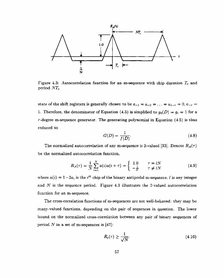
Figure 4.3: Autocorreiation function for an rn-sequence nith chip duration Tc and period NTc
- state of the shift registers is generally chosen to be a-1 = a-7 = . . . - al - , = O' a-, =
1. Therefore, the denominator of Equation (4.5) is simplified to go(D) = gr = 1 for a
r-degree m-sequence generator. The generating polynomial in Equation (4.5) is thus
reduced to 1
The normalized autocorrelation of any m-sequence is P-valued [33]. Denote Re&)
be the normalized autocorrelation funct ion?
where a( i ) = 1 -2a, is the ilh chip of the binary antipodal rn-sequence. 2 is any integer
and AT is the sequence period. Figure 4.3 illustrates the 2-valued autocorrelation
function for an m-sequence.
The cross-correlation functions of m-sequences are not well-behaved: they may be
many-valued functions. depending on the pair of sequences in question. The Iower
bound on the normalized cross-correlation between any pair of binary sequences of
period N in a set of m-sequences is [47]:

There exist composite code families t hat utilize- the ni-sequences to produce sets
of low cross-correlation codes. The Gold and Kasarni codes are among these and they
are widely used in practice as spreading sequences.
4.2 The Gold Sequences
The Gold code sets [44, 453 are generated by the summation of two distinct m-
sequences of the same period. Consider a binary m-sequence of penod N and let it
be represented by the vector a. Consider another sequence a' obtained by sampling
every qth symbol of a. The sequence a' is said to be a decimation of sequence a and is
denoted as a' = a[q]. It is proveo that the sequence a' is a m-sequence with penod N
if and only if gcd(N, q ) = 1, where "gcd(a, b)" denotes the greatest common divisor
of integer a and b [48]. Thus, any pair of m-sequences having the same period N
can be related by a' = a[q] for some q. The two m-sequences a and a' are called the
preferred pair if the following two conditions are satisfied:
1. r # O(mod4), where r is the degree of the shift register, and
2. q is odd and either q = 2' + 1 or q = 22k - 2k + 1 for some k
1 for r odd gcd(r, k) =
2 for r = 2(mod4)
If a and a' is a preferred pair, then the family of Gold codes
t hat sat isfies
(4.1 1)
for this preferred
pair of m-sequences is defined by {a, a'? a + a': a + Da', a + ~ ~ a ' , . . . , a t DN-la'}
where D is the delay element. The cross-correlation functions of the Gold farnily are
three-valued, where those three values are {-F, - k, k [t(r) - 211, and
for r odd for r even.
Tt is easily verified that the number of codes in the Gold farnily is N + 2 where N is
the sequence period.
Figure 4.4 illustrates the generation of a Gold sequence using two m-sequences
whose primitive polynomials are fi (D) = 1 + 0 + D3 and f2(D) = 1 + D2 + D3. The
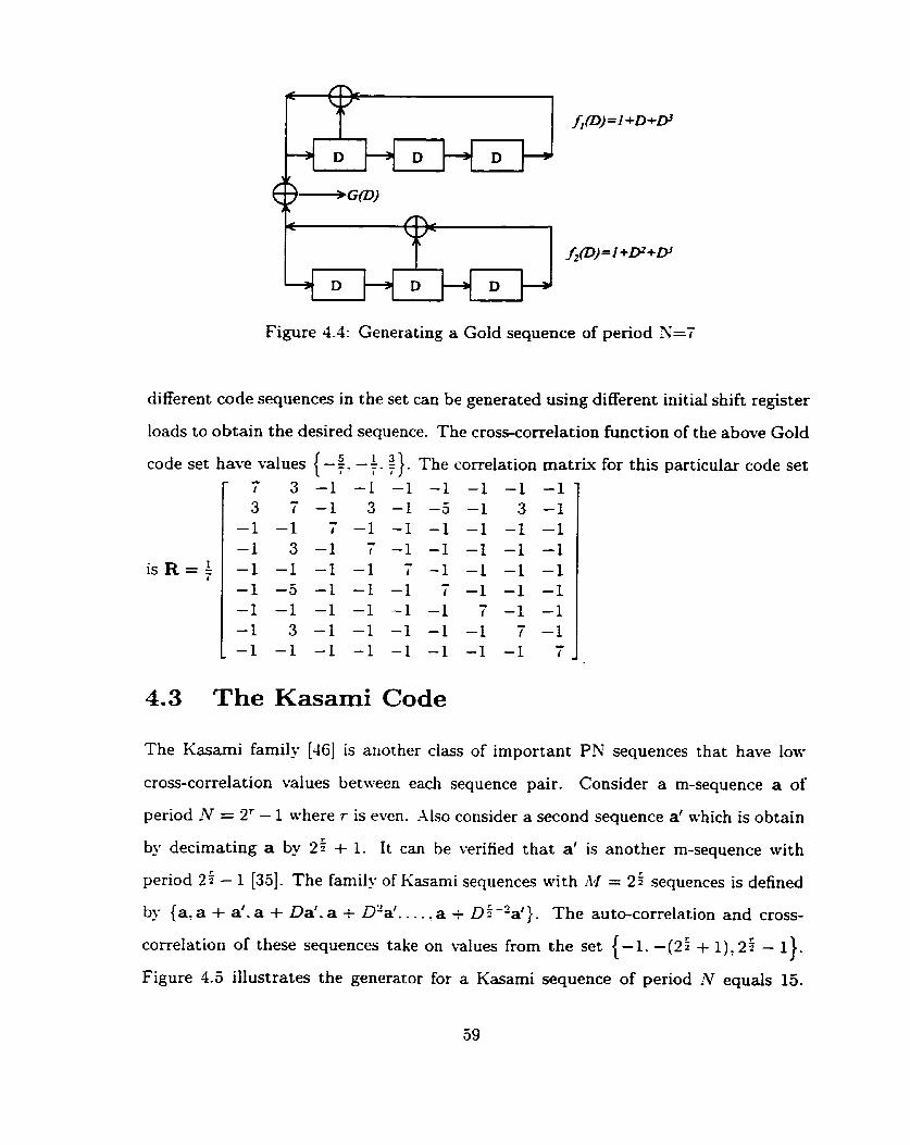
Figure 4.4: Generating a Gold sequence of period N=7
different code sequences in the set can be generated using different initiai shift register
loads to obtain the desired sequence. The cross-correlation function of the above Gold
4.3 The Kasami Code
code set have values {-$. -$. q } . The correlation rnatrk for this particular code set
The Kasami family [46] is ariother class of important P N sequences that have low
is R = $
cross-correlation values between each sequence pair. Consider a m-sequence a of
- L
r 3 -1 -1 -1 -1 -1 -1 -1 - 3 7 -1 3 -1 -5 -1 3 -1
-1 -1 7 -1 -1 -1 -1 -1 -1 c. -1 3 -1 1 -1 -1 -1 -1 -1 - -1 -1 -1 -1 r -1 -1 -1 -1 - -1 -5 -1 -1 -1 r -1 -1 -1 - -1 -1 -1 -1 -1 -1 r -1 -1
-1 3 -1 -1 -1 -1 -1 T -1 - _ -1 -1 -1 -1 -1 -1 -1 -1 r _
period N = 2' - 1 where r is even. -Usa consider a second sequence a' which is obtain
by decimating a by 25 + 1. I t can be verified that a' is another m-sequence with
period 25 - 1 [35]- The family of Kasami sequences with M = 25 sequences is defined
by {a'a + a'. a + Da'. a + D'a'. . . . a t Di-2a'}. The auto-correlation and cross-
correlation of these sequences take on values from the set {-1: -(25 + l), 25 - 1).
Figure 4.5 illustrates the generator for a Kasami sequence of period !V equals 15.
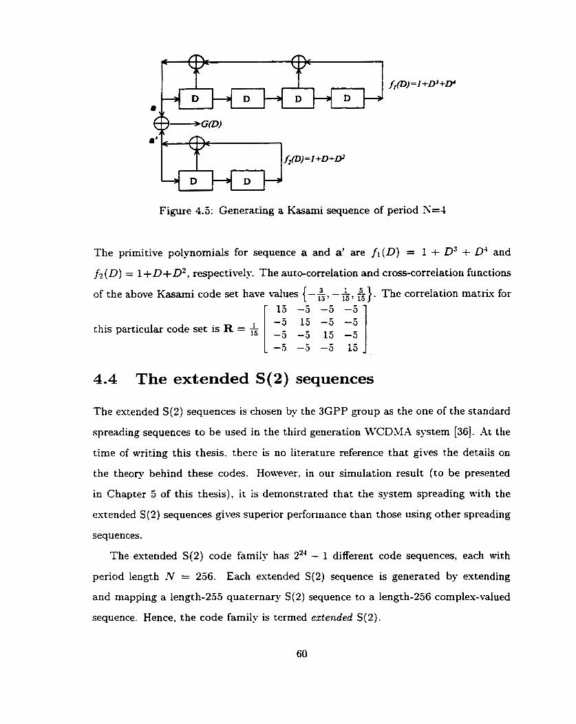
Figure 4.5: Generating a Kasami sequence of period 3=4
The primitive p o l ~ o m i a l s for sequence a and a' are fi(D) = 1 + D3 + D4 and
f2 ( D ) = 1 + D +D2, respectively. The auto-correlation and cross-correlation functions
of the above Kasami code set have values {-&, -&, 5). The correlation matriu for r 13 -3 -5 -a 1
4.4 The extended S(2) sequences
this particular code set is R =
The extended S(2) sequences is chosen by the 3GPP group as the one of the standard
spreading sequences to be used in the third generation MiCDM.4 system [36]. At the
time of writing this thesis. there is no literature reference that gives the details on
the theory behind these codes. However. in Our simulation result (to be presented
in Chapter 5 of this thesis). it is demonstrated that the system spreading with the
extended S(2) sequences gives superior performance than those using other spreading
sequences.
The extended S(2) code family has 224 - 1 different code sequences, each with
period length ?V = 256. Each extended S(2) sequence is generated by extending
and mapping a length-255 quaternary S(2) sequence to a length-256 cornplex-valued
sequence. Hence, the code family is termed extended S(2).
-5 15 -5 -3 - - 15 -5

mod 2 1 ? I
@ multiplication
@ rnod n addition
Figure 4.6: The S(2) sequence generator
Each S(2) sequence is generated by modulo-4 addition of a quaternary sequence,
{ a r } : and 2 bina- sequences. {bi) and { d l ) These three sequences are 8-degree
LSFR sequences and are generated recursively according to the follon-ing generating
polynornials:
The generator for the S(2) code is shown in Figure 4.6. The initial loads for the
three LFSRs are determined froin the user number. Let jZ3 j2* . - . jO be the 24 bit
bina^ representation of the user number j, O 5 j 5 255. The initial loads are
a,l = 2 j o + 1 mod4,
a-i = 2ji,1 mod4, i = 2 . . . 8 .
b,i = jiCi mod 2, i = 1 . . .8.
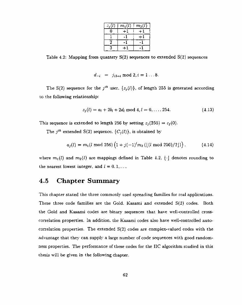
Table 4.2: Mapping from quantery S ( 2 ) sequences to extended S(2) sequences
d-i = jlS+* mod 2, i = 1 . . -8.
The S(2) sequence for the j th user, {z,(i)}: of length 252 is generated according
to the folloning relationship:
~ ~ ( 1 ) = ai + 2br + 2dr mod 4 ,1 = 0: . . . .254. (1 .13)
This sequence is extended to length 236 by setting zj (255) = zj (O) -
The jth extended S(2) sequence. (C,(l)), is obtained by
a j ( l ) = n l ( l mod 236) ( 1 i j(-l) 'm2 ( L ( 1 mod 2 5 6 ) / 2 ] ) ) . ( 4 . 1 4 )
where m l ( l ) and m z ( l ) are mappings defined in Table 1.2: L-] denotes rounding to
the oearest lowest integer: and 1 = 0: 1:. . ..
4.5 Chapter Summary
This chapter stated the three commonly used spreading families for real applications.
These three code families are the Gold. Kasami and estended S(2) codes. Both
the Gold and Kasami codes are bina- sequences that have well-controiled cross-
correlation properties. In addition. the Kasami codes also have wll-controlled auto-
correlation properties. The estended S(2) codes are comples-valued codes nith the
advantage that they can supply a large number of code sequences mith good random-
ness properties. The performance of these codes for the IIC algorithm studied in tbis
thesis wïIl be given in the foilowing chapter.

Chapter 5
Iterat ive Interference Cancellat ion for High Data Rate Users in WCDMA
In contrast to Chapter 3, the performance of different IC schemes are verified in this
chapter using a more refined CDM-4 mode1 where actuai spreading takes place. This
chapter begins with the detail system parameters used in the cornputer simulations to
assess performance. The performance of different IC algorithms on common spreading
codes used in practice, such as the Gold, Kasami, and extended S(2) codes, are
presented. In the computational results to be given in this Chapter which involve
the use of a pre-processor. the MMSE case defined in Equation (3.16) was employed
as the pre-processing sub-system. This was done to avoid the possibility of having a
singular matrix to define the pre-processor which can occur for the decorrelator case.
5.1 System parameters
In this thesis, our system is targeted at the 384 kbps third-generation WCDMA
service. The available channel bandwidth, Wo for WCDMA is about 5MHz [4]. When
rate-; convolutional code is employed, the processing gain of the particular system is
given by

nhere B is the bandwidth of the encoded bit. To achieve the desired BER of
IO-'' the required SXR for a rate-?, constraint length 7, convolutional code is equal to
45dB [3]. Using Equation (2.10), only 5 users can be supported by such system a i t h
a processing gain of 7 when conventional CDMA detector without MUD is employed.
5.2 Iterative Interference Cancellation with differ- ent spreading sequences
Methods of spreading can be divided into 2 categories: spreading using sequences
with period larger than the bit period. i.e., N > PG. and spreading using sequences
with period equal to the bit period, i.e., N = PG. These two types of spreading
are referred as long and short spreading, respectively, in this thesis. The use of long
spreading complicates the task of MUD [?] since the code segments used for spreading
va- for each data syrnbol. On the other hand, the identical cross-correlation matrL~
in short spreading simplifies MUD, but a good spreading code family does not exist
for al1 period lengths N. Table 5.1 shows the number of available sequences of each
code family for a given period length N. Given a system with processing gain of 7,
the only code family with such a period length is the 3-degree Gold famil. Thus, the
3-degree gold code set is considered for short spreading, while the Kasami and the
estended S(2) codes are used for long spreading in this thesis.
5.2.1 Spreading with Gold sequences
The 3-degree Gold code set %th penod length AT = 7 is generated by using primitive
polynomials fi (D) = 1 + D2 + D3 and f2(D) = 1 + D + D3 (341. This code set has
only 9 available sequences and thus only 9 users can be supported. This Gold code
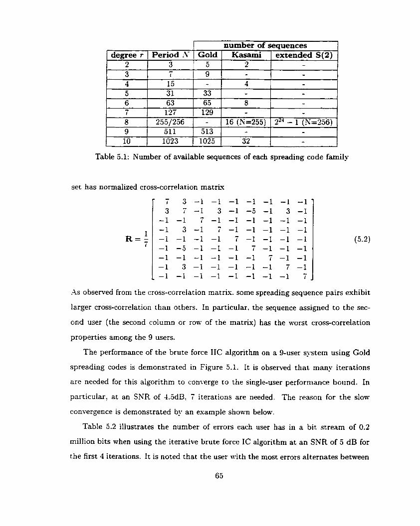
I number of seauences 1
Table 5.1: Number of available sequences of each spreading code family
set has normalized cross-correlation matLu
degree r
-4s observed from the cross-correlation matris. some spreading sequence pairs exhibit
larger cross-correlation than others. In particular. the sequence assigned to the sec-
ond user (the second column or row of the matr~x) has the worst cross-correlation
properties among the 9 users.
The performance of the brute force IIC algorithm on a 9-user system using Gold
spreading codes is demonstrated in Figure 5.1. It is observed that many iterations
are needed for this algorithm to converge CO the single-user performance bound. In
particular: at an SNR of 43dB. 7 iterations are needed. The reason for the slow
convergence is demonstrated by an esample shown telow.
Table 5.2 illustrates the number of errors each user has in a bit Stream of 0.2
million bits when using the iterative brute force IC algorithm at an SNR of 5 dB for
the first 4 iterations. It is noted that the user with the most errors alternates between
2 3
2 -
Period L\. i Gold Kasami
4 5 6 7 8 9 10
- -
ixtended S(2) 3 - 1
3 - 9
- - - -
z2' - 1 (X=226) - -
l a 31 63 127
255/256 511 1023
- 33
4 -
65 '
129 -
513 1025
8 -
16 (3=255) -
32
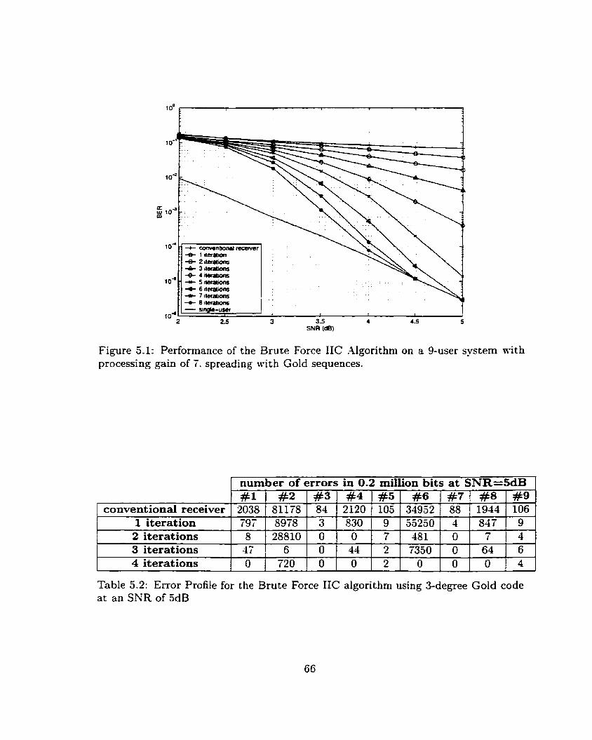
Figure 5.1: Performance of the Brute Force IIC Algorithm on a 9-user system n-ith processing gain of 7. spreading ~ l t h Gold sequences.
1 number of errors in 0.2 million bits at SNR=SdB 1
I I 1 I 1 1 1 I 1
2 iterations 1 8 1288101 O 1 O T 7 1 4 8 1 1 O 1 7 1 4 1 conventional receiver
1 iteration
1 I t 1 1 I 1 I r
3 iterations l 4 ? ! 6 1 O 1 4 4 1 2 1 7 3 5 0 1 O 1 6 4 1 6 1
Table 5.2: Error Profile for the Brute Force IIC algorithm using 3-degree Gold code at an SNR of 5dB
1
#3 84 3
#l 2038 797
#9 106 9
#a 81178 8978
#4 2120 830
#5 105 9
#6 34952
#7 88
#8 1944
53250 1 4 847

the second and the sixth user at each successive stage. This alternating phenomenon
is the key reason for the slow convergence. and the esplanation for this phenomenon
is as follows.
In order to obtain performance gain through the use of the parallel interference
cancellation algorithm, the A,I-kI estimation used must be relatively more reliable than
the received signal for the user in question. That is, the decoder decisions made for
the interfering users must be more reliable than the decoder decisions made for the
user in question. For the case shown in Table 5.2, performing IC on the second user
at the first iteration removes most of the MAI and resuits in fewer errors because
the estimated k1--1 is obtained from relatively reliable sources. On the other hand,
performing IC on the s ~ x t h user worsens its performance due to the unreliable 11-41
estimation caused bu the second user. Recail from Equation (2.13) that an incorrect
bit decision made for a particular user doubles its MAI contribution and further
degrades the quality of signal in question. Since the cross-correlation value between
the second user and the s h t h user is large. i.e., f i s = - k. I . the degradation caused
by an incorrect decision is detrimental. Therefore, at the end of the first iterative
IC stage. the sixth user resuits in more errors than its previous stage. Follo~ving the
same arguments, the sisth user results in fewer errors but the second user results in
more errors at the end of the second iteration. This situation keeps alternating until
the IC algorithm or the decoder makes no further improvement. Xotice that this
alternating phenomenon does not occur for users other than those mentioned above.
This is mainly due to the good crosçcorrelation properties between the other users
and the two aforementioned users. Therefore, the impact of performing IC using
incorrect estimates of both the second and the sixth users is not as detrimental.
-At a first glance. one might believe that serial caricellation is the best candidate
for solving the aforementioned problem. Serial cancellation works weli when the users
are received with unequal power strengths. In such a case. stronger users are usually
the reliable users and they contribute a larger percentage of the interference power

toward the nreaker users. Howevert in a case n-hen each user pair has its ou-n cross-
correlation. the reliable users are those who interfere other users the least 11-hile the
unreliable users are those who interfere others the most. Therefore. these two cases
are not equiwient. Fortunatelx a somewhat similar approach can be employed to
lower the initial BER for the two dominant interfering users to accelerate con\-ergence.
The algorithm used n-il1 be called the preliminary IC algorithm.
The preliminary IC algonthm is ernployed pnor to the regular IIC algorithm to
improve the initial XI,U estimation for a feu7 selected users. These users are usu-
ally the dominant interfering users and are determined by the cross-correlation ma-
trix. Starting with the most dominant interfering user. the preliminary IC algorithm
successively improves the fidelity of the estimated MAI for the user in question by
utilizing the result obtained from the previous stage of this algorithm. Figure 5.2
illustrates the procedures of a Su-user preliminary IC algorithm. Suppose the mobile
users are ranked with a lower index indicating a more unreliable user. The prelim-
inary IC is a simplified 4L-stage parallel IC algorithm where neither decoding nor
encoding procedures are involved. It uses the initial decoder decisions to improve
the estimation on the matched-filter outputs for the first ,Y, users on a user-by-user
b a i s and provides an improved -\LAI estimate at the end of the algorithm. Recall -0
that bj = [ bYl0 . . . &?-'*O ] denotes the estirnated received sequence for the j th -re f ined
user based on initial decoder decisions. Let b, = [ $.re fined 'L,- ivre fined ... b, 1 be the refinement of $ resulting from the preliminary IC algorithm. ;\t each stage
-re f ined x, 15 x 5 Xu, o, is obtained frorn an IC process for the user in question using
-re f ined -0 the refined received sequences 4, . I 5 n 5 rr - 1. and the original sequences on, x 5 n 5 1%. The algorithm continues for each user in succession until al1 -\-u users
are considered.
The procedure of the brute force IIC algorithm with a Su-stage preliminary IC
prior to its first iteration is formulated as follows:
Step(l) Initialization:
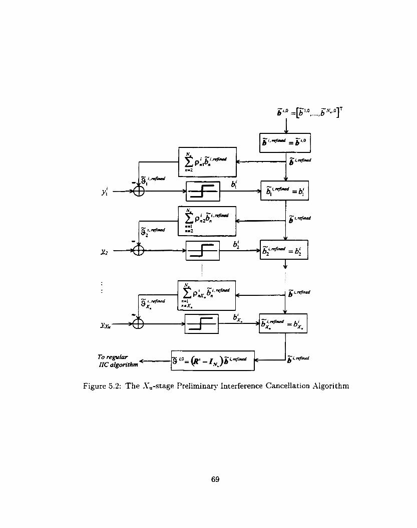
Figure 5.2: The &stage Preliminap Interference Cancellation .Algorithm
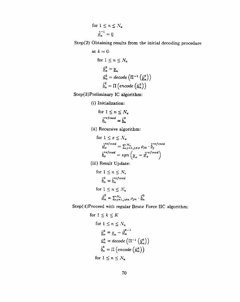
Step(2) Obtaining results from the initial decoding procedure
for 1 5 n 5 Nu -0 Y , = &
ü0 = decode (II-1 (2)) -n -0 on = n (e7zc.de (Q )
S tep (3) Preliminary IC algorit hm:
(i) Ini tialization:
for 1 5 n 5 AT,
iref incd - -0 -n - bn
(ii) Recursive algorit hm:
aref ined hr -re f ined
-x = EjZl Pjz bj bref incd -z = sgn (% - -r arefined)
(iii) Result Update:
for 1 < n 5 !Vu
Step(4) Proceed with regular Brute Force IIC algorit hm:
for 15 n < i& -k- 1
?jk = - gn -n
Ü" ddecode (II-1 (Q")) -n 4
-k on = il (encode (g:))
for l < n 5 1%

2 2 5 3 3.5 4 4.5 5 SNR (dB)
Figure 5.3: Performance of the Brute Force IC on a 9-user system with processing gain
IIC Algorithm with a 2-stage preliminary of 7, spreading with Gold sequences.
3' = p u -n ) = i j # n Pjn . bj
Step(5) Final decisions:
for 1 5 n 5 hYu
- -.ch' I n - -n
Figure 5.3 shows the performance of a 9-user CDMh srstem with a 2-stage prelimi-
nary IC algorithm prior to the first iterative stage of the regular IIC algorithm. The
two selected users are the second user and the sisth user gken in Table 5.2 according
to the cross-correlation matris in Equation (3.2). It is shown in Figure 5.2 that an
accelerated rate of convergence is pursuant which is attnbuted to the use of the pre-
liminary IC algorithm. Kote also that only 5 iterations are required for converging to
the single-user bound when the SXR is equal to 4.5dB. The improved performance
is obtained by an estra step that searches for the dominant interfering users. Notice
that the prelirninary IC algorithm does not require the decoding, encoding, interleav-
ing and deinterleaving procedures. Therefore. the delay incurred is minimal when

compared to the regular IIC aigorithm.
Partial interference cancellation or soft interference canceilation can also be a p
plied to the prelimina- IC algorithm as a further enhancement. Interference can-
cellation using the partiai preliminary IC algorithm is formulated by modifying the
third step from the ordinary p re i iminq IC algorithm as fol!ows:
Step(3)Preliminary IC algorithm:
(i) Initializat ion:
for 1 5 n 5 -Nu
iref lned -n = b0 -n
(ii) Recursive algorit hm:
f o r l ~ x < X ' ,
aref ined hU -r = YTe El=lj+r P ~ Z - -j irefined - te f ined k = sgn (& - -r arefined)
(iii) Result C'pdate:
where yPre denotes the fraction to cancel for the prelirnin ; IC dgorithm.
The soft preliminaq IC cancellation is formuiated by modifying the same step as
Step (3) Preliminary IC algorit hm:
(i) Initialization:
-re f ined -O - on - bn
(ii) Recursive algorithm:

(iii) Result Update:
,PO = pu -n j=ij+n P j n mdti
where 40, denotes the reliability sequence for the nth user gimn by the initial decoding
procedure and rnulti(at b) denotes element-by-element multiplication of vector a and
vector 6.
2 5 3 35 4 5 SNR (dB)
Figure 5.4: Performance of the Brute Force IIC Algorithm combined with a 2-stage Partial Pre l iminq IC on a 9-user system with processing gain of 7. spreading with Gold sequences.
Figures 5.4 and 5.5 demonstrate the performance of using partial preliminary
cancellation and soft preliminary cancellation, respectively. Both algorithms converge
to the single-user performance bound in 4 iterations at an SXR of 4.5dB. For the case
in Figure 5.5. the soft preliminary IC algorithm converges faster in the low-SNR
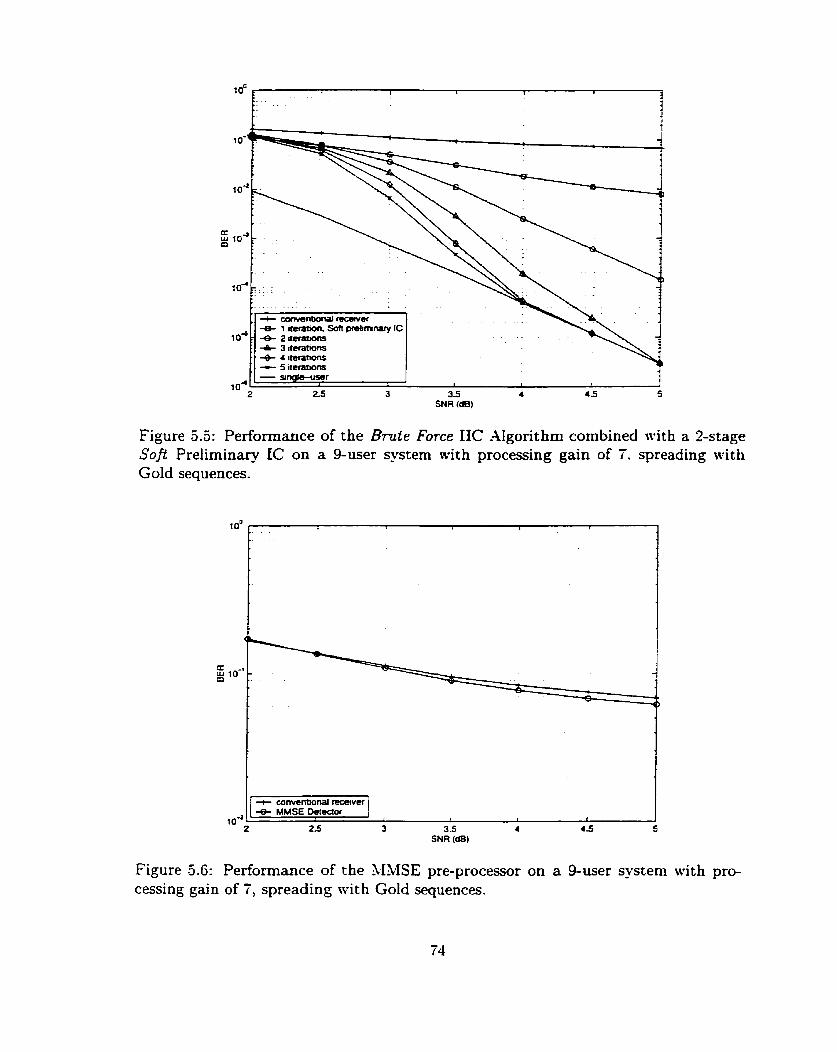
Figure 5.5: Performance of the Brute Force IIC AIgorithm combined with a 2-stage Soft Preliminary ZC on a 9-user system with processing gain of 7. spreading with Gold sequences.
Figure 5.6: Performance of the MMSE pre-processor on a 9-user system with pro-
I
Y
cessing gain of 7, spreading with Gold sequences.
1 o4
+ convenhonal recenier 4 MMSE Deimor
1 f 1
2 25 3 3.5 4 4 5 5 SNR (dB)
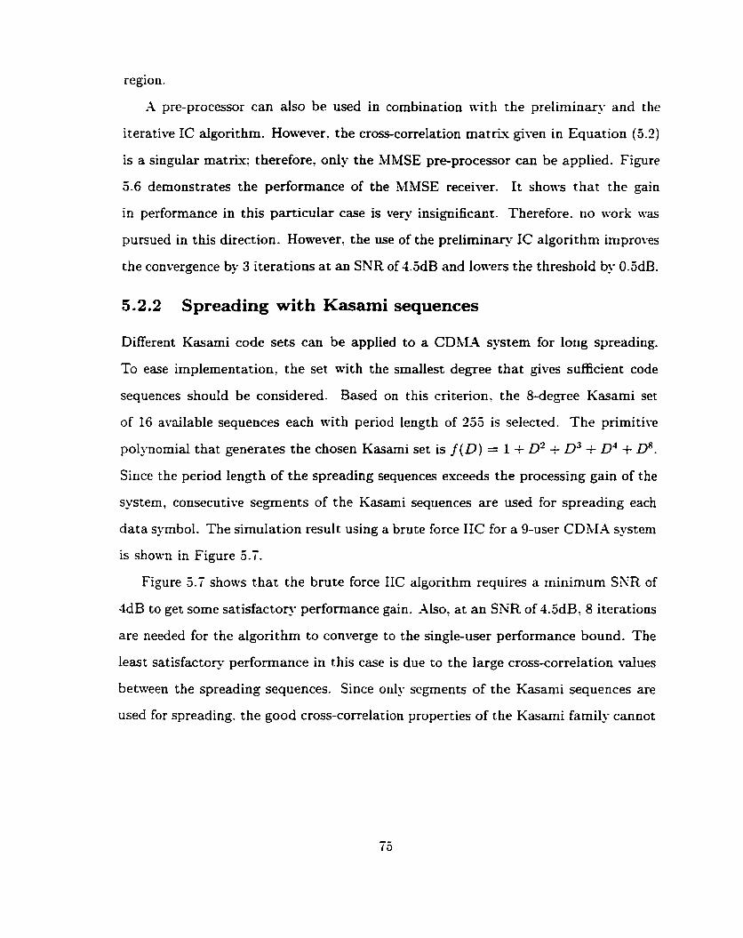
region.
-4 pre-processor can also be used in combination with the preliminary and the
i t erative IC algorit hm. However, the cross-correlation m a t r k given in Equat ion (3 2 )
is a singular matrix: therefore. only the MMSE pre-processor can be applied. Figure
5.6 demonstrates the performance of the bIbISE receiver. It shows that the gain
in performance in this particular case is v e l insignificant. Therefore. no work was
pursued in this direction. However: the use of the preliminary IC algorithm improves
the convergence by 3 iterations at an SNR of 4.5dB and ion-ers the threshold by O.5dB.
5 2 . 2 Spreading with Kasami sequences
Different Kasami code sets can be applied to a CDM-4 system for long spreading.
To ease irnplernentati~n~ the set with the smallest degree that gives sufficient code
sequences should be considered. Based on this criterion. the 8-degree Kasami set
of 16 available sequences each with period length of 255 is selected. The primitive
polj-nomial that generates the chosen Kasarni set is f ( D ) = 1 + D2 + D3 + D4 + Da. Since the period length of the spreading sequences esceeds the processing gain of the
system. consecutive segments of the Kasami sequences are used for spreading each
data symbol. The simulation result using a brute force IIC for a 9-user CDM-4 system
is shown in Figure 5.7.
Figure 5.7 shows that the brute force IIC algorithm requires a minimum SKR of
4dB to get some satisfactory performance gain. Jllso' a t an SNR of 4.5dB: 8 iterations
are needed for the algorithm to converge to the single-user performance bound. The
least satisfactory performance in this case is due to the Iarge cross-correlation d u e s
between the spreading sequences. Since only segments of the Kasami sequences are
used for spreading. the good cross-correlation properties of the Kasami familj. cannot

Figure 5.7: Performance of the Brute Force IIC algorithm on a 9-user system with processing gain of 7, spreading with Kasami sequences.
be maintained. -4 typical cross-correlation matris obtained from the simulation is
Figure 5.8 shows the simulation result of using a partial cancellation algorithm
with cancellation fractions of 60% for the first iteration and 100% for the remaining
iterations. Total convergence requires 4 iterations at an SNR of 4.5dB for this algo-
rithm. which is an improvement of 4 iterations n-hen compared to the brute force IIC
algorithm. Note that the threshold SNR is also lowered from 4dB to 3.5dB.
The performance of the soft IIC algorithm on Kasami sequences is shown in Figure
9 In the high-SNR region. the soft algorithm gives similar performance as the
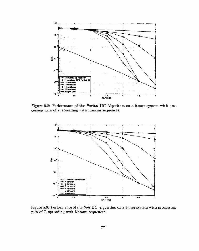
Figure 5.8: Performance of the Partial IIC Algorithm on a 9-user system 111th pro- cessing gain of 7, spreading with Kasami sequences.
SNR (dB)
Figure 5.9: Performance of the Soft IIC -Algorithm on a 9-user system with processing gain of 7: spreading with Kasami sequences.

Figure 5.10: Performance of the Pre-processor-aided Brute Force IIC algorithm on a 9-user system nith processing gain of 7, spreading with Kasami sequences.
partial algorithm. In the lon-SNR region. the soft algonthm performs significantly
better. The threshold SNR is further lowered to 3dB by the soft IIC algorithm.
Pre-processing can also be applied to each IIC algorithm to achieve better per-
formance. Figure 5.10 shows the result of using a XISISE pre-processor in combi-
nation with the brute force IIC algorithm. Only 3 iterations are required for such
an algorithm to converge to the single-user bound at an SYR of 4.5dB. which is an
improvement of 1 iteration relative to the partial IIC case and 5 iterations relative
to the brute force case. Howec-er, the improvement is obtained at the espense of
increased computational complesity. In the case of Kasami codes ( N = 255) and the
estended S(2) codes ( N = 256) to follow. the matrix (R + 91~") in Equation (3.16)
must be computed and inverted on a symbol-by-symbol basis. The pre-processor mas
not used for the short Gold code. but if it is used. the MMSE matris is required to
be computed once.
Figures 5.1 1 and 5.12 show the performance of using a MMSE pre-processor in

Figure 5.1 1 : Performance of the Pre-pmcessor-aided Partial IIC Algorithm on a 9- user system with processing gain of 7: spreading nith Kasami sequences.
SNR (dB)
Figure 3.12: Performance of the Pre-processor-aided Soft IIC -4lgorithm on a 9-user system with processing gain of 7. spreading wit h Kasami sequences.

-e- average MMSE receiver
IO-= I I 1
2 25 3 3.5 4 4 5 5 SNR (dB)
Figure 5.13: A cornparison on average hISISE detector and optimal MMSE detector
combination with the partial cancellation and the soft cancellation algorithm. respec-
tivel. Both algorithms accelerate the convergence rate especially in the Ion-SNR
region. The threshold SSR is lowered to 3dB for the partial IIC case and 2.5dB for
the soft IIC case.
Instead of using a different 31MSE pre-processor for each symbol interval, the
performance of using an average &I.\ilSE pre-processor is studied. The average MXISE
pre-processor is obtained by
where R = EL, R' is the average cross-correlation matris. iV is the period length
of the spreading sequence. R' is given in Equation(2.27). 2 is power spectral density
of the noise in -4IVGX cchannel. and Inru is an ArK x i\i, identity matrix Figure 5.13
compares the performance of the conventional receiver: the average MMSE receiver
and the optimal MMSE receiver. The figure shows that the average MMSE receiver
is quite inferior to both the optimal MMSE receiver and the conventional receiver.
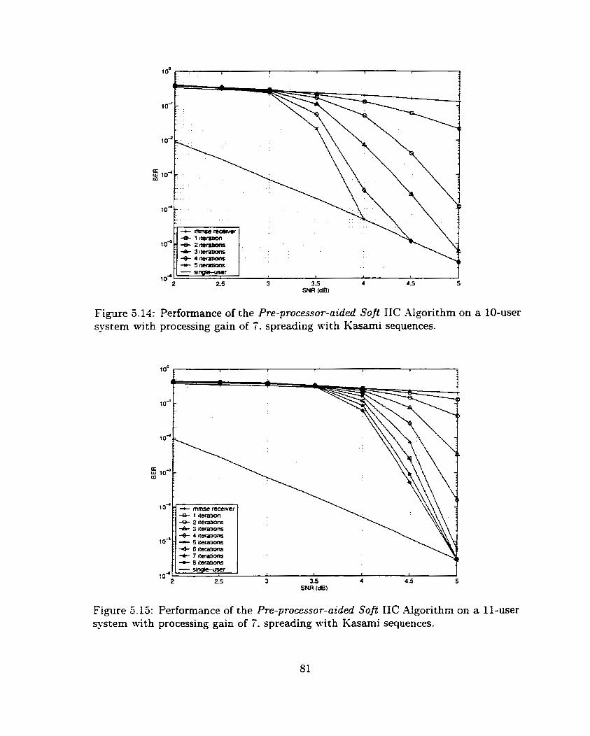
Figure 5.11: Performance of the Pre-processor-aided Soft IIC .Algorithm on a 10-user system with processing gain of 7. spreading with Kasami sequences.
Figure 5-15: Performance of the Pre-processor-aided Soft IIC Algorithm on a Il-user system \vit h processing gain of 7. spreading wi t h Kasami sequences.
With the optimal h1XfSE pre-processor. more than 9 users can be supported using
the soft IIC algorithm. Figure 5.14 and 5-15 show the simulation resuits for a 10- and
Il-user system, respectivel. At an SNR of 4.5dB, 4 iterations are required to achieve
the desired performance tevel for the 10-user -stem. However. many iterations are
required for the Il-user system to achieve the same performance level. Sote that
an SNR of at l e s t 3.5dB is needed to get an- reasonable performance gain for the
10-user system.
5.2.3 Spreading with extended S (2) sequences
The implementation i>f the estended S(2) code ntas presented in Chapter 1. Adopted
by the 3GPP group. this code family is designed to give a large number of sequences
with good cross-correlation properties (361.
The extended S(2) family with period length rV = 236 has 2*" - 1 available code
sequences. Each user selects its spreading sequence according to its user number.
Figure 5.16 demonstrates the performance of the brute force IIC algorithm on
a 9-user system spreading with extended S(2) sequences. -At an SYR of 4.5dB, 5
iterations are needed to converge to the single-user bound. Comparing to the case
when Kasami sequences are used (see Figure 5.7) . the estended S(Z) codes perform
relatively better. Fewer number of iterations are required for the system employing
the estended S(2) sequences to converge to the single-user bound at any given SXR.
Figures 5.17 and 5.18 demonstrate the performance of the partial and soft inter-
ference cancellation algorithms. respectivel. Total convergence requires 3 iterations
for the partial algorithm and 4 iterations for the soft algorithm a t an SXR of 4.SdB.
These 2 algorithms both lower the threshold SXR from 3.5dB to 2.5dB when com-
pared to the brute force case. Xotice that the partial IIC algorithm converges faster
in the high-SNR region for this case. When the decoder decisions on the interfering
users are reliable, a large cancellation fraction gives better performance than a small
one. Thus, soft IIC may not give better results when compared to the partial IIC in

2 2 5 3 3 5 4 5 SNR (dB)
Figure 5.16: Performance of the Brute Force IIC Algorithm on a 9-user system with processing gain of 7: spreading mith estended S(2) sequences.
4 1 ilerahon. oInb Parbal 1C 1 O* 4 2 flCrah0ftS
j -& 3 rterabons . +- 4 ~leralions . - 5 itemions
2 2.5 3 3.5 4 4 5 5
Figure 5.17: Performance of the Partial IIC -Algorithm on a 9-user system with processing gain of 7: spreading with extended S(2) sequences.

Figure 5.18: Performance of the Soft IIC Algorithm on a 9-user system with process- ing gain of 7, spreading with estended S(2) sequences.
the high-SNR region.
Figure 5-19 shows the performance of the pre-processor-aided brute force IIC
algorithm. Only 3 iterations are needed at an SNR of 4.5 dB to converge to the
single-user bound. which is an irnprovement of 2 iterations compared to the non pre-
processed case in Figure 3.16. Compared to the soft IIC case in Figure 5.18: the
pre-processor-aided brute force algorithm does not perform as me11 in the low-SNR
region. The t hreshold SXR for the pre-processor-aided brute force algorithm and the
soft IIC algorithm are about 3.5 and 2.5 dB. respectively.
\frithout the aid of the pre-processor, the systern that employs soft IIC can support
11 users. Figures 5.20 and 3.21 demonstrate the performance of a 10- and Il-user
system. respectively. For the IO-user system. 6 iterations are required at an SXR of
4.5dB to achieve a BER of IO-". For the Il-user system. T iterations arc required.
The threshold SKR for these 2 systems are 3dB and 3.5dB. respectively.
With the aid of the pre-processor, the Il-user system ernploying the soft IIC al-

Figure 5.19: Performance of the Pre-processor-aided Brute Force IIC -Aigorithm on a 9-user systern with processing gain of 7: spreading n-ith estended S(2) sequences.
SNR (dB)
Figure 5.20: Performance of the Soft IIC -Algorithm on a 10-user system cessing gain of 7, spreading with extended S(2) sequences.
with pro-

Figure cessing
5.21: Performance of the Soft IIC algorithm on a Il-user systern gain of 7. spreading with estended S(2) sequences.
with pro-
Figure 5.22: Performance of the Pre-processor-aided Safi IIC algorithm on a Il-user systern with processing gain of 7: spreading with extended S(2) sequences.
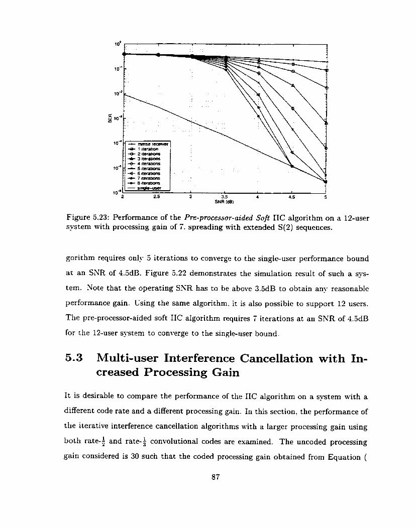
Figure 5.23: Performance of the Pre-pmcessor-aided Soft IIC algorithm on a 12-user system with processing gain of 7. spreading with extended S(2) sequences.
gorithm requires only 5 iterations to converge to the single-user performance bound
at a n SNR of 4.3dE. Figure 5.22 demonstrates the simulation result of such a sys-
tem. Note that the operating SXR has to be above 3.5dB to obtain any reasonable
performance gain. Csing the same algorithm. it is also possible to support 12 users.
The pre-processor-aided soft IIC algorithm requires T iterations at an SNR of 4.5dB
for the 12-user system to converge to the single-user bound.
5.3 Multi-user Interference Cancellation with In- creased Processing Gain
It is desirable to compare the performance of the IIC algorithm on a system with a
different code rate and a different processing gain. In this section. the performance of
the iterative interference cancellation algorithms with a larger processing gain using
both rate-$ and rate-f convolutional codes are esamined. The uncoded processing
gain considered is 30 such that the coded processing gain obtained from Equation (

5.1) are 15 and 10 for the rate-; and rate-$ code. respectively. The spreading code
farnily considered in this section is the extended S(2) code. It is shown in the previous
section that the systeïn using the estended S(2) sequences gkes superior performance
to those using the Gold or Kasami sequences.
To achieve a performance level of BER=10-'. the rate-?. constraint length 7. con-
volutional coded system employing conventional detector can support 6 simultaneous
users ulth a required SNR of 4.5dB.
Figure 5.24 demonstrates the performance of the brute force IIC algorithm on
a lbuser system using rate 4 convolutional code with coded processing gain of 15.
To achieve a BER of IO-': 4 iterations are needed for the brute force algorithm to
converge to the single-user performance at an SNR of 4.5dB. Sotice that the number
of user that can be simultaneously supported by the CDM-4 system employing IIC
algorithm is tripled when the uncoded processing gain is increased to 30.
Figure 5.25 demonstrates the performance of the brute force IIC algorithm on a
18-user system using rate-) code. The FEC code considered is the constraint length
9 convolutional code with generators (557.663.711) in octal. To achieve the desired
performance level. Le.. BER=10-'. 4 iterations. determined from Figure 5.25. are
required at an SKR of 3.5dB. Thus. the performance gain in terms of the convergence
rate obtained by using a lower rate code is insignificant. Hon-ever. the rate f code
requires a lower SXR to achieve the same performance level. This gain is obtained at
an increased computational complexity at the decoders.
5.4 Chapter Summary
The performance of the IIC algorithms with different spreading sequences are studied.
When the 3-degree Gold spreading sequences are used, the regular IIC algorithm fails
to provide a satisfactory performance. To solve this problem, a preliminary IC algo-
rithm is developed to accelerate the convergence rate. Using the partial preliminary
IC algorithm on a 9-user system. an improvement of 3 iterations is obtained at an
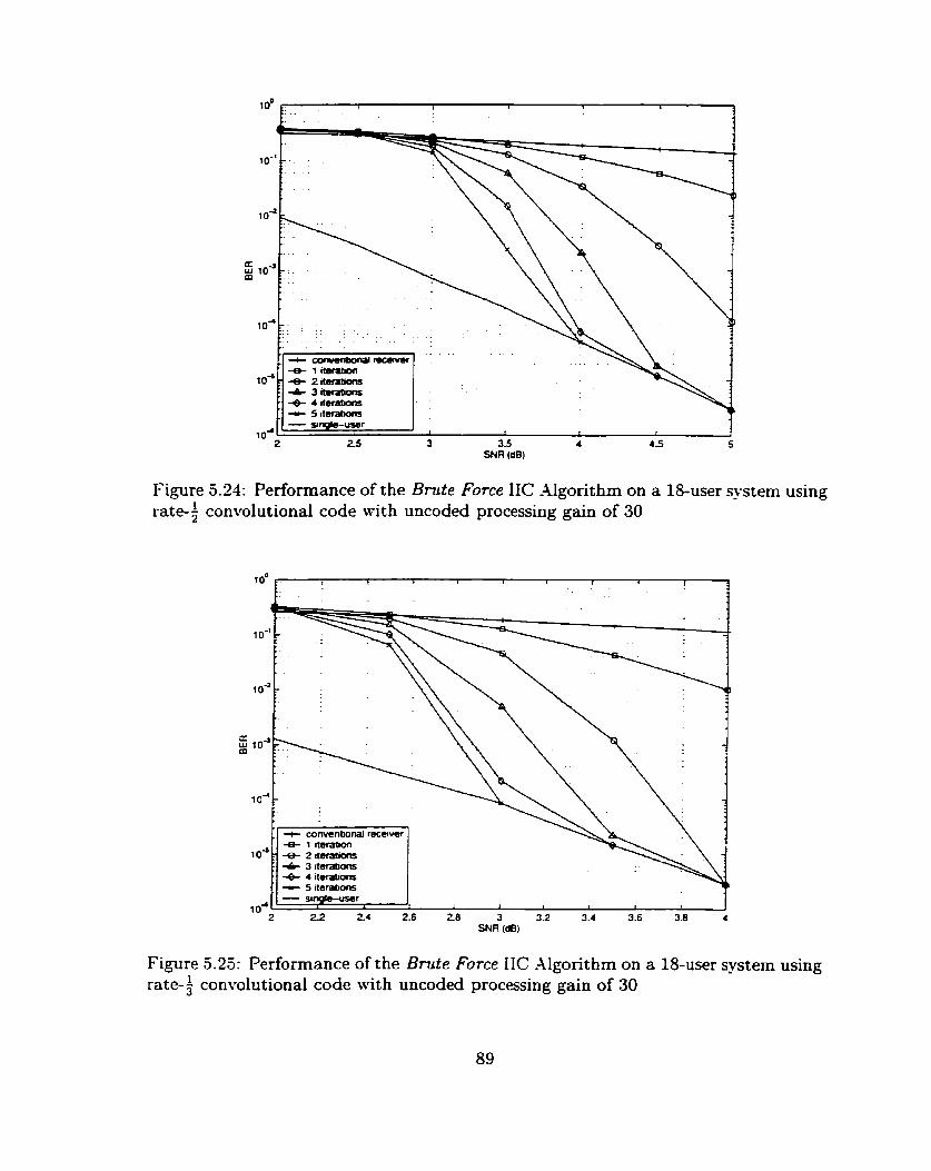
SNR (dB)
Figure 5.24: Performance of the Brute Force IIC Algorithm on a 18-user system using rate-; convolutional code with uncoded processing gain of 30
4 1 neratcon IO" 7 + 2 mations
I 4- 3 Rerarions + 4 ctara0ons
22 2 4 2.6 28 3 32 3.4 3.6 3.8 4 SNR (dB)
Figure 3.25: Performance of the Brute Force IIC Algorithm on a 18-user system using rate-+ convolutional code with uncoded processing gain of 30
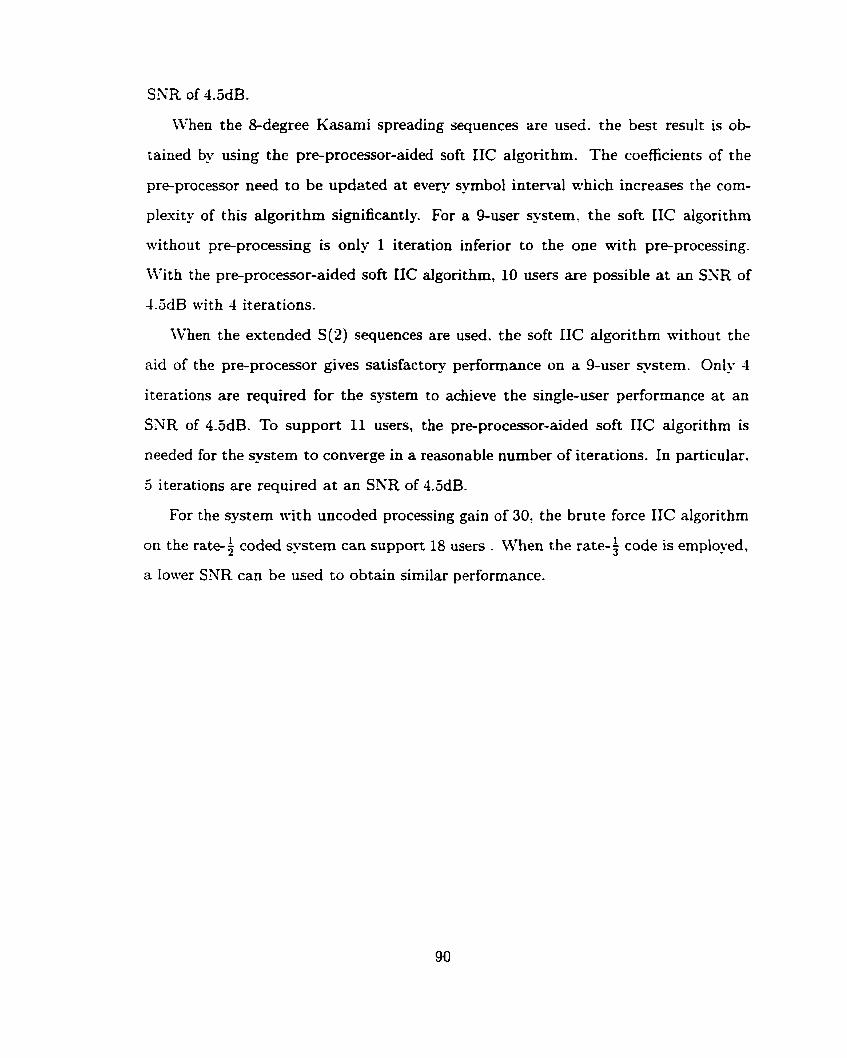
SNR of 4.5dB.
IVhen the 8-degree Kasami spreading sequences are used. the best result is ob-
tained by using the pre-processor-aided soft IIC algorithm. The coefficients of the
pre-processor need to be updzted at every s-vmbol interval which increases the corn-
plesity of this algorithm significantly. For a 9-user system, the soft IIC algorithm
without pre-processing is only 1 iteration inferior to the one with pre-processing.
With the pre-processor-aided soft IIC algorithm, 10 users are possible at an SNR of
4.5dB with 4 iterations.
When the extended S(2) sequences are used. the soft IIC algorithm without the
aid of the pre-processor gives satisfactory performance on a 9-user system. Only 4
iterations are required for the ?stem to achieve the single-user performance at an
SXR of 4.5dB. To support 11 users, the pre-procesor-aided soft IIC algorithm is
needed for the system to converge in a reasonable number of iterations. In particuiar.
5 iterations are required at an SNR of 4.5dB.
For the system with uncoded processing gain of 30, the brute force IIC algonthm
on the rate-; coded system can support 18 users . When the rate-? code is employed.
a lower SNR can be used to obtain similar performance.

Chapter 6
Conclusions
6.1 Conclusions
The performance of muhi-user interference cancellation algorithms in a convolutional
coded CDM-4 system was evaluated in this thesis. The following points summarize
the major results:
1. For the AWGK channel, the use of an iterative interference cancellation algo-
rithm can double the number of high-bit-rate users in WCD3.I-1. In the case of
Gold codes, 9 users can be supported 11-hen the soft preliminary IC algorithm
is employed. in the case of Kasami codes. 10 users can be supported when the
pre-procesor-aided soft IIC algorithm is used. For the same algorithm, 11 users
can be supported in the case of extended S(2) codes.
2. The use of the 3-degree Gold spreading sequences demonstrates a phenornenon
where a particular user signature sequence esperiences much stronger interfer-
ence than other users in the system. In this case, the preliminary IC algorithm
is required to obtain satisfactory performance.
3. The performance of IIC on the estended S(2) codes is superior to that of the
Kasami codes. For each IC scheme. fewer number of iterations are required for
the system empIoying estended S(2) sequences to converge to the single-user
performance bound.

4. The amount of improvement obtained frorn the pre-processor-aided IIC varies
wit h the channel characteristics such as the cross-correlation values. In the
case of the Gold spreading sequences, the performance gain £rom using a pre-
processor is very insigdcant. On the other hand, improvements of a iterations
for the Kasami sequences and 2 iterations for the extended S(2) sequences are
O btained when compared to the non-pre-processed cases.
6.2 Suggestions for F'uture Work
The use of iterative interference cancellation algorithrns was shown to increase
user capacity of the CDMA system. Such results were obtained by cornputer
simulations that assumed perfect carrier and timing s~chronizat ion. One
should investigate the sensitivity of these algorithms without these assump
tions.
Perfect power control was also assumed in this thesis. One should consider
studying these algorithms with power control error.
In order to perform MUD: the knowledge of channel parameters are required. It
would be desirable to combine channel estimation with interference cancellation
and study the sensitivity of estimation error.
The work in this thesis was focused on the .4WGN channel. It would be desirable
to study the IIC algorithms under a channel model that includes shadow fading.
The CDM-4 model used in this thesis was idealized. I t would be desirable to
apply the IIC algorithm to a cellular structure with both inter-ce11 and intra-ce11
interference.
The performance of the soh IIC algorithm in this thesis was studied based on
the use of the SOV-4 decoding algorithm. It would be desirable to study the
same algorithm using the MAP decoder.
92

7. The spreading codes used in practice are designed without having hfUD in mind.
These spreading codes may not give the best performance under the LlLD
algorithms. For instance. the performance gain of using MMSE detector for a
system using Gold spreading sequences and a system using Kasami spreading
sequences are significantly different. This is due to the structural differences
in the crosscorrelation matrk- Therefore. it is desirable to design spreading
sequences that are optimized for MUD.

Bibliography
[Il Stephen G. Wilson. Digital Modulation and Coding. Prentice Hall. 1996.
[2] Stephen B. Wicker. E v o r Control Systems for Digitcl Communication and Stor- age. Prentice Hall, 1995.
[3] Andrew J. Viterbi and Jim K. Omura. Principles of Digital Communication and Coding. McGraw Hill? 1979.
141 M. Zeng, A. Annamalai, and V.K. Bhargava. Harmonization of Global Third Generation Mobile Systems. Proceedings, 20th Biennial Symposium on Com- rnunc~tions, Queen's - ~ n i u e r s i t ~ , Kingston Ontario, pages 139-143. May 2000.
Andrew J. Viterbi. CDMA: Principles of Spread Spectrum Communications. Addison 1995.
Rarnjee Prasad and Tero Ojanpera. Wideband CDMA for Third Generation Mo bile Conrnunications. Artech House Pu blishers. Boston. 1998.
Sergio Verdii. Multiuser Detection. Cambridge University Press. 1998.
Sergio Verdii. Optimum sequence detection of as_vnchronous multiple-access com- munications. Abstr. 1983 IEEE Internation Symposium. o n Information Theory, page 80? Sep 1983.
Sergio Verdu. Minimum probability of error for asynchronous multiple access communication systems. Proceedings, 1983 IEEE Military Communications Con- ference, pages 213-219. 1983.
K. Schneider. Optimum detection of code division multiplesed signals. IEEE Transactions on Aerospace and Electronic Systems, AES-15 (1): l8l- l8$ Jan 1979.
U. Madhow anà M. L, Honig. MMSE interference suppression for direct-sequence spread spectrum CD&1,4. IEEE Transactions on Communications, 42:3178-3188, Dec 1994.
hilahesh K. Varanasi and Behnaam Aazhang. hlultistage Detection in Asyn- chronous Code-Division multiple-,Access Communications. I E E E Transactions on Communications, 38(4):509-519, -4pr 1990.
Mahesh K. Varanasi and Behnaam Aazhang. Sear-Optimum Detection in Syn- chronous Code-Division Multiple-Access Systems. IEEE Transactions o n Com- munications, 39(5) :725-736, May 1991.
[14] Young C. Yoon, Ryuji Kohno. and Hideki Imai. -4 Spread-Spectrum hIultiaccess S-tem with Cochannel Interference Cancellation for Multipath Fading Chan- nels. IEEE Transactions on Communications. 11-7: 1067- 1075. Sep 1993.
[15] P.S. Guinand and Michael Aloher. Serial interference Cancellation for Highly Correlated Users. IEEE Pacific Rim Conference on Communications. Computers and Signal Processing, pages 133-136, 1999.
[16] Dariush Divsaiar and Marvin Simon. hproved CDM-4 Performance Gsing Par- allel Interference Cancellation. J P L Publicution. 95-21. October 1995.
[li] Markku Juntti, kIatti Latva-aho, and Kimmo Kansanen Olli-Pekka Kaurahalme. Performance of Parallel Interference Cancellation for CDM-4 with Delay Estima- tion and Channel Coding. Proceedings, I E E 5th International Symposium on Spread Spectrurn Techniques and Applications. 3:936-940. 1998.
[18] Matti Latva-aho and Jorma Lilleberg. Parallel Interference Cancellation - -1 Mul- tiuser Detection Framework. Symposium on Interference Rejection and Signal Separation in Wireless Communication, pages 127-146, Mar 1996.
[19] M. Latva-Aho, M. Juntti, and K. Kansanen. Residual interference suppression in parallel interference cancellation receivers. IEEE International Conference on Communications. 2:927-931. 1999.
[?O] Sergio Verdu. Demodulation in the presence of mulitaccess interference: Progress and misconceptions in intelligent methods in signal processing and communica- tions. pages 15-46. Birkhauser. 1997.
[21] C. Berrou. -4. Glavieux, and P. Thitimajshirna. Xear Shannon error-correcting coding and decoding: Turbo-codes (1). Proceedings, 1993 International Confer- ence on ~ornmunications, pages 1064-1070. 1993.
[22] Michael hloher. An Iterative Multi-user Decoder for -4synchronous BPSK Users. Proceedings, 1998 International Symposium on Information Theory, page 423, 1998.
[23] Michael Moher. An Iterative Multi-user Decoder for Near-Capacity Communi- cations. IEEE Transactions on Communications. 46-7:870-880. July 1998.
[21] Mark C. Reed. Christian B. Schlegel. Paul D. Alexander: and John -4. Asen- storfer. Iterative .\lultiuser Detection for CDXIA with FEC: Near-Single-User Performance. IEEE Transactions on Communications. 46(12):1693-1699. July 1998.
[25] Hesham Gama1 and Evaggelos Geraniotis. Iterative llultiuser Detection for coded CDM-4 signals in AWGX and Fading channels. IEEE Journal on Selected Areas in Communications. 18(1):30-41, January 2000.
[26] Xiaodong Wang and H. Vincent Poor. Iterative (turbo) soft interference cancel- lation and decoding for coded cdma. IEEE Transactions on Communications. 47(7), July 1999.

Xiaodong Wang and H. Vincent Poor. Turbo Multiuser Detection for Turbo- coded CDMA. IEEE Wireless Commvnications and Networking Conference. 3. September 1999.
S. Wijaya~uriya~ G. Sorton, and J. McGeehan. -4 Xovel Algorithm for Dynamic Ci pdating of Decorrelator Coefficients in Mobile DS-CD hLA. Proceedings of the 4th International Symposium on Personal, Indoor and Mobile Radio Cornmuni- cations, pages 292-296, Oct 1993.
Alexandra Duel-Hallen: Jack Holtzman, and Zoran Zvonar. Multiuser detection for CD hL4 systerns. IEEE Personal Communications Magazine. 2 ( 2 ) :46-58. Apr 1995.
John G. Proakis and Masoud Salehi. Cornmunicatiun Systerns Engineering. Pren- tice Hall, 1994.
W. Wesley Peterson, Roger E. Ziemer, and David E. Broth. Introduction to Spread Spectrum Communications. Prentice Hall. 1995.
George R. Cooper and Clare D. McGillem. Modem Commvnications And Spread Spectrum. McGraw-Hill. 1986.
Solornon W. Golomb. Shift Register Sequences. Holden-Day, 1967.
CI'. Wesley Peterson and Jr E. J. Weldon. Error- Cowecting Codes. hIIT Press. 1961.
Esmael H. Dinan and Bijan Jabbari. Spreading Codes for Direct Sequence CDh.IX and Wideband CDMA Cellular Xetwork. lEEE Cornminications Magazine, pages 48-54? September 1998.
Third-Generation Partnership Project Group. Technical Specification Group Radio -Access Setwork; Spreading and Modulation (FDD). http://www. 3gpp. org, 3G TS 25.213 version 3.1.0. December 1999.
Joachim Hagenauer and Peter Hoeher. -4 Viterbi -4lgorithm with Soft-Decision Outputs and its applications. Proceedings of IEEE Globecom Conference, pages 47.1.1-47.1.7. Xov 1989.
A. Kajiwara and 3.1- Kakagawa. 5licrocellular CDM-4 System with a Linear hl ultiuser Interfererce Canceller. IEEE Journal on Selected Areas in Communi- cations, l2-4:605-6 1 1 : May 1994.
R. De Gaudenzi, C. Elia, and R. Viola. Bandlimited Quasi-Synchronous CD-UIA: -4 Novel Satellite -4ccess Technique for Mobile and Persona1 Communication Systern. IEEE Journal on Selected Areas i n Cornm.t~nications, S-C-10-2328- 343, February 1992.
R. Lupas and Sergio Verdii. Near-Far Resistance of 34 ultiuser Detectors in A s p - chronous Channels. IEEE Transactions on Communications, COM-38-4:496- 508, April 1990.
Theodore S. Rappaport. Wireless Communications: Pn'nciples and Practice, volume IEEE Press. PH. 1996.

[42] P. Elias. Coding for noisy channels. IRE Conv. Record. 3:37-46. 1955.
[43] -2ndren J. Viterbi. Error bounds for convolutional codes and an asymptoticall?- optimum decoding algorithm. IEEE Transactions on Information Theoq. IT- l3(2): 260-269. Apr 1967.
[44] R. Gold. Optimal binary sequences for spread spectrum multiplesing. IEEE Transactions on Information Theory, pages 619-621. Oct 1967.
[45] R. Gold. Maximal recursive sequences Nith bcalue recursive cross-correlation function. IEEE Transactions on Information Theory, IT-4154-156. Jan 1968.
[16] T. Kasami. Weight distribution formula for some class of cyclic codes. Coordi- nated Science Lab, Uniu. IL, Urbana. Tech. Rep., pages R-285. Apr 1966.
[47] L. R. Welch. Lower Bounds on the Maximum Cross Correlation of Signais. IEEE Transactions on In fomat ion Theory, IT(20):397-399, May 1974.
[48] D. V. Sarwate and M. B. Pursle. Crosscorrelation properties of pseudorandom and related sequences. Proc. IEEE, 63:593-6 19, h~lay 1980.
[19] Yue K. J. Lau. Arithmetic Error Correcting Codes for Fault-Tolerant Digital Signal Processing in Processing Satellite Applications. In Master Thesis. Queen's Universit~., 1992.
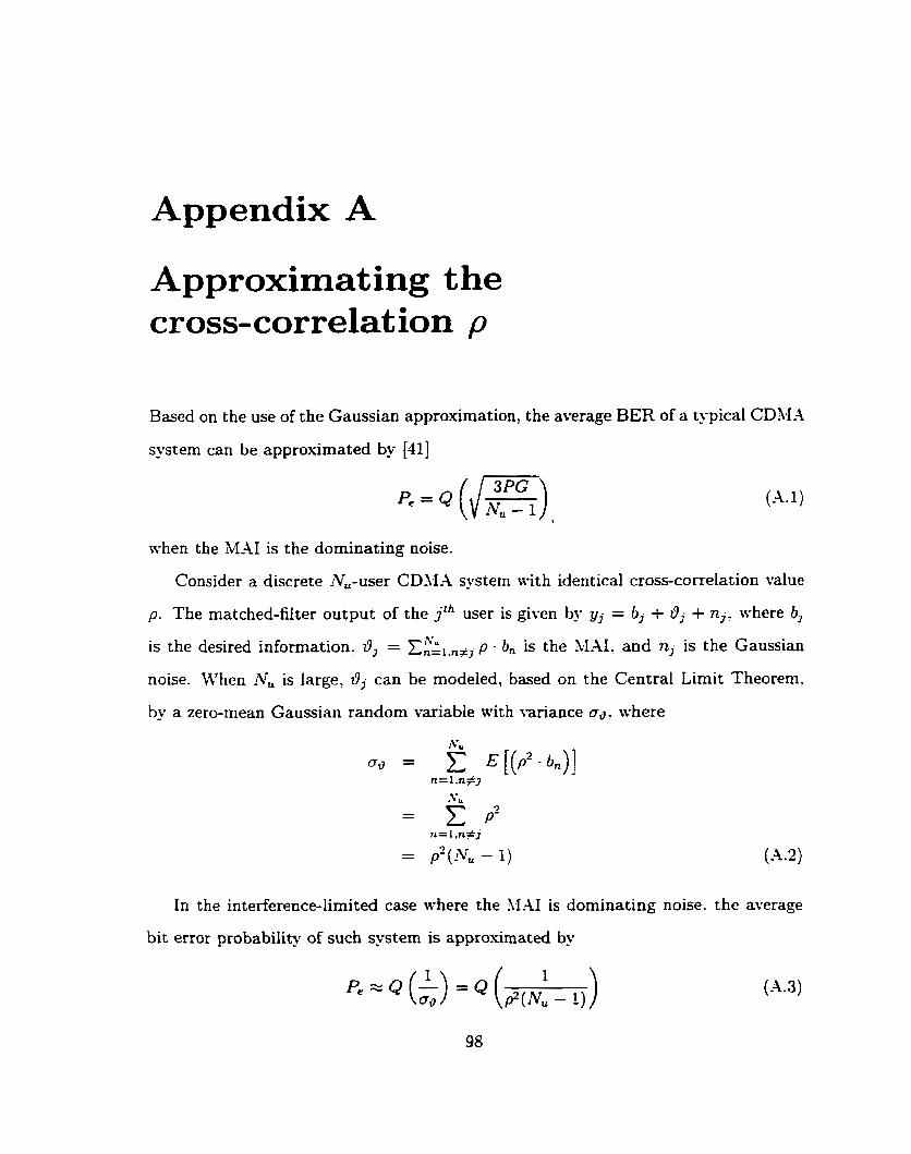
Appendix A
Approximat ing the cross-correlat ion p
Based on the use of the Gaussian approximationo the average BER of a tj-pical CDM-4
system can be approximated by [dl]
(A. 1)
mhen the MAI is the dorninating noise.
Consider a discrete Nu-user CDbIA system nith identical cross-correlation value
p. The matched-filter output of the j th user is given by yj = bj + O j + nj. where 6,
is the desired information. 0, = x;ginw p - b, is the MAI. and nj is the Gaussian
noise. When AT, is large, dj can be modeled, based on the Central Limit Theorem.
by a zero-mean Gaussian random variable with variance od, shere
In the interference-limited case where the ILAI is dominating noise. the average
bit error probability of such system is approximated by

* -ta-/?
where Q ( x ) denotes 1: .%du.
The cross-correlation value p is appro-ximated bu equating (-4.1) and (-4.3).
In our typical CDM-4 system with processing gain of 7, the cross-correlation p is
approximately equal to 0.22.

Appendix B
Simulations and the Confidence Int ervals
The simulation results presented in this thesis are obtained based on the Monte-Carlo
method. To get an indication of the accuracy of the simulation results. the statistical
confidence intervals were used. The number of simulation trials (number of bits sent)
required to achieve a desired confidence level were derived in [49] using the Chernoff
bound. Table B.1 re-states the results obtained in [19].
The simulation results in this thesis are aimed such that the siniulated BER is
within 3~30% of the true BER with 95% confidence. To achieve the target confidence
level. a minimum of 8.98 x 10⁶ trials are required for a BER of IO-'. Thus. the
simulations in this thesis use a bit Stream of 1 x 10' bits.
1 BER ( 95% certain / 95% certain 1 95% certain 1 99% certain 1 within 30% ( within 20% within 10% within 10%
10-' 8.00 x 10² 1 1.755 x 10³ 6.833 x lo3 9.814 x 10⁴ IO-' 8.88 x lo3 1 1.943 x 10⁴ 7.541 x 10⁴ 1.083 x 10⁵
Table B.l: The number of bits required to achieve different confidence intervals