Embed Size (px)
Citation preview

Interfacing an ipod to a Mazda 6 Factory stereo By Joseph Haas © 2/04/2012 This story has its beginnings in my childhood. I was always curious about how things worked. TVs, Radios, teletypewriters, lawnmower engines, you name it and I probably took it apart. The putting back together was never as interesting, so I rarely bothered myself with that part of the exercise (much to my parent’s dismay). What does all that have to do with controlling an ipod from my factory built, in-car stereo? Well, this project was not about saving money, and it was not about doing what was easy. I could have bought a new stereo or even a Sylfex AuxMod and it would have been much easier, and cost less. This project was about taking a sliver of knowledge and materials, and turning it into a greater knowledge. I wanted to see if I could figure out how to make my car stereo control my ipod. If, in the end, I have a useable product that performs a desirable function, then, all the better. In short, most folks reading this will feel compelled to ask “Why?” My best response is simply “Why not?” OK, enough with the rationalizations… I’m not new to the world of ipod control. I was part of a two man team in 2004 that designed one of the first ipod docks to hit the market. You likely have never seen or heard of it since it was over-priced and late to market. However, the experience left me with some knowledge of how to accomplish ipod control, and some leftover hardware that could be used in the endeavor. In addition, as I was to find out, many others have made the foray into the world of ipod control, most much further than I, so there is a wealth of information out there on ipod communications protocols and the like. More daunting was the Mazda Stereo. Figuring out how the interconnection between my interface and the stereo would work would end up being the bulk of the effort in this project. More Recently… This project started in earnest around May of 2011. For various reasons, I found myself contemplating an increased frequency of long road trips to visit my family. The average trip was 11 to 12 hours by car and while I have a 6 CD changer in my vehicle, I don’t like swapping CDs, and would much prefer using my ipod (even though it is a 2004 vintage nano, it still works). I had built a small interface board that would allow me to use a PC style headset to listen to the ipod and also perform a hands free phone interface to my MotoRazr. It worked pretty well (legal implications of wearing an over-the-ear headset while driving notwithstanding) but wearing a headset for more than a couple of hours at a time starts to

become uncomfortable. Also, if anyone else in the vehicle would like to listen to my music (however unlikely) they would be forced to listen carefully to the faint sound of my headphones.
Image 1. My first headset, ipod, Razr cell phone, & ham radio interface Technically the interface worked well, but did suffer from one problem: There was significant “ground loop” noise that was prevalent while the ipod was connected to a car charger (as was nearly always the case since the batteries for the older ipods are notorious for early wear-out, as was the case for my nano). I had heeded (or so I thought) the requirement that the ipod audio ground *not* be tied to the system ground, but still with the noise. My thought was that you didn’t want to make a metallic (AKA galvanic) connection to the ipod audio ground to avoid any current flow due to any differential in voltage between the two ground points, so I used a large value capacitor. It wasn’t until I started considering this problem more carefully, that I realized that, while the capacitor blocked any DC current flow, it still allowed AC current to flow. Thus, as the ipod performed different operations, the varying current in the ipod charger ground lead would show up as a voltage that became superimposed on the audio signals. Thus, even if you didn’t connect the audio ground at all, you would still see the noise on the audio signals. This leads to an aside: The noise wasn’t due to a “ground loop”. A ground loop results when there are multiple conductive ground paths between which there is a voltage differential. In the case of the ipod, the noise is the result of noise currents that manifest as noise voltages across a non-zero ground impedance. But I digress. Filtering the power to the ipod is one alternative. Here, you want to use a common mode inductor and a capacitor to isolate the power connection to the charger source. As you increase the value of L and C, the low-pass cutoff frequency (Fc = 1/2π√LC) decreases -- make them large enough, and this would tend to make the ipod look more like it was

floating on its internal battery. The problem with this approach is that you need to have values of L and C such that they form a low-pass filter with a cut-off frequency well below 20Hz (the normal low-end of the human range of hearing sensitivity). While achievable, the values needed make the components very large. In the end, such a filter would end up being the size of a grapefruit (give or take… or was it a grape?). Finally, I realized that I needed a differential amplifier to buffer the audio coming from the ipod. A differential amplifier would cancel the common mode noise that would be superimposed on both the ipod analog ground and the audio signals, while amplifying/buffering the differential audio signals. I use difamps often and they are well suited to converting a signal with a reference that is not (or not quite) ground, and converting it to a ground referenced output. I ginned up a difamp for my ipod/Razr interface and violà, no more noise. The only caveat is that the audio shield connection from the ipod could not come into contact with any other ground point. In fact, the audio shield had to be treated like any other signal. Sylfex I’ve never met or spoken with anyone at Sylfex (www.sylfex.com), but I e-mailed them a couple of times. I was searching for audio input options for my Mazda, and their web site came up. They had several (grainy) pictures that were still interesting. This allowed me to see what the back side of my stereo likely looked like, and I also got to see the connector that plugs into the empty bay of said stereo (Oh, did I mention that there is an empty bay in my stereo, with a corresponding blank cover that ostensibly could accept a mini-disk player, or satellite receiver? Which begs the question, “Why not an auxiliary audio input?”). I’ve worked around connectors for industrial and MIL/aero products for most of my life, and this connector was totally new to me. I didn’t even know what to call it, and I certainly didn’t know where to find one. The other tidbit I took from the Sylfex web site was that they had the same problem with ipod audio noise that I had experienced (as did many other interfaces). So universal was the issue, that there were several products out there to address the noise. These “ground loop interrupters”, or GLIs, isolate the ipod audio from the intended destination. Usually, these were little more than a pair of audio isolation transformers. I saw some mention of a “FET GLI” on a web site somewhere, but no more description than that. My interpretation of that term is that the FET GLI devices used a differential amplifier, just like the circuit I had put to use for the same purpose. Seeing that Sylfex had the same problem, and that they had something I needed, I e-mailed with an offer to provide a working circuit that they could then incorporate into their product in return for a single one of the funky Mazda accessory connectors. I was politely, but succinctly refused. As it turns out, that was the best news for me because I had also found someone on e-bay who had several cassette tape decks for a Mazda Miata available for only $35 shipped.
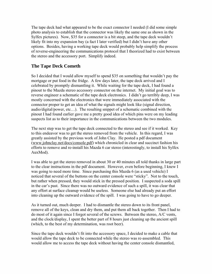
The tape deck had what appeared to be the exact connector I needed (I did some simple photo analysis to establish that the connector was likely the same one as shown in the Sylfex pictures). Now, $35 for a connector is a bit steep, and the tape deck wouldn’t likely fit into my expansion bay (a fact I later verified) but I didn’t have any other options. Besides, having a working tape deck would probably help simplify the process of reverse-engineering the communications protocol that I theorized had to exist between the stereo and the accessory port. Simplify indeed. The Tape Deck Cometh So I decided that I would allow myself to spend $35 on something that wouldn’t pay the mortgage or put food in the fridge. A few days later, the tape deck arrived and I celebrated by promptly dismantling it. While waiting for the tape deck, I had found a pinout to the Mazda stereo accessory connector on the internet. My initial goal was to reverse engineer a schematic of the tape deck electronics. I didn’t go terribly deep, I was mostly concerned with the electronics that were immediately associated with the connector proper to get an idea of what the signals might look like (signal direction, audio/digital/power, etc…). The resulting snippet of a schematic combined with the pinout I had found earlier gave me a pretty good idea of which pins were on my leading suspects list as to their importance in the communications between the two modules. The next step was to get the tape deck connected to the stereo and see if it worked. Key to this endeavor was to get the stereo removed from the vehicle. In this regard, I was greatly assisted by the previous work of John Clay. He posted a pdf document (www.johnclay.net/docs/console.pdf) which chronicled in clear and succinct fashion his efforts to remove and re-install his Mazda 6 car stereo (interestingly, to install his Sylfex AuxMod). I was able to get the stereo removed in about 30 or 40 minutes all told thanks in large part to the clear instructions in the pdf document. However, even before beginning, I knew I was going to need more time. Since purchasing this Mazda 6 (as a used vehicle) I noticed that several of the buttons on the center console were “sticky”. Not to the touch, but rather when pressed, they would stick in the pressed position. I suspected a soda spill in the car’s past. Since there was no outward evidence of such a spill, it was clear that any effort at surface cleanup would be useless. Someone else had already put an effort into cleaning up the outward evidence of the spill. I was going to have to go deeper. As it turned out, much deeper. I had to dismantle the stereo down to its front panel, remove all of the keys, clean and dry them, and put them all back together. Then I had to do most of it again since I forgot several of the screws. Between the stereo, A/C vents, and the clock/display, I spent the better part of 8 hours just cleaning up the ancient spill (which, to the best of my determination, was root beer). Since the tape deck wouldn’t fit into the accessory space, I decided to make a cable that would allow the tape deck to be connected while the stereo was re-assembled. This would allow me to access the tape deck without having the center console dismantled,

allowing the car to be used normally during my efforts (which would span several weeks, at best). Of course, having the stereo relocated to my lab/office would have been preferable, but this was out of the question for several reasons. I removed the funky connector from the tape deck, and fashioned a piece of double sided, blank FR4 (fiberglass) PCB material to allow the connector to be installed and attached with about 3 feet of cable. I used a standard 15 pin DSUB connector to replace the hi-jacked connector at the tape deck end and then I was ready to see if my stereo would even recognize the new tape deck.
Image 2. A view of the “funky” tape deck connector Behold, the Glory of the Cassette Tape… The tape deck worked, much to my relief. A minor victory to be sure, but after so much work cleaning and reverse engineering, it was welcome news to know that I had a working tape deck. Next, I needed to see what some of those pins were doing. I pulled my oscilloscope from its perch over my work bench and took it on safari. Mind you, if I could have pulled my car into my office, I would have in a heartbeat. The Texas heat is notorious, even at night, and this year has been excessive even by Texas standards. After a few minutes, I am able to reduce my list of several suspects down to just one. The signal labeled as BUS+ (pin 1 of the funky connector) from my web searchings is the only signal that seems to do anything in response to stereo key presses (or anything other than be at a constant voltage, for that matter). Data comes in bursts at about a 1 second rate (or in relatively immediate response to a key press). At first I assume it is Manchester encoded data, but upon expanding the data and looking at the timing, I realize that it is bi-phase encoded. Bi-phase data is basically a PWM (pulse width modulated) signal with only two distinct modulation settings. One of the primary advantages of bi-phase is that it is a relatively easy task to synchronize the receiving clock during data reception since each bit is transmitted between clock edges that are always separated by the same time period. It is also relatively easy to visually decode the bits from an oscilloscope display. However, the volume of data (between 10 and 35 bits each burst) make that cumbersome to do for more than a few bits at any given sitting (that, or I’m just lazy).

Image 3. BUS+ data captured on a TEK-2440 DSO So, the next step is to build a decoder to receive and display the data (preferably on a PC) so that I can decode the bit patterns. Ultimately, I need a processor to emulator the tape deck and send ipod commands, so building a piece of hardware is not an unnecessary effort considering that this same hardware can be used later for the interface. I have several prototype boards that I had made for a processor I use at work (the SiLabs C8051F120). The boards have a power supply and the minimum necessary components to get the processor up and running. The remaining board area features a prototyping array of pads spaced at 50 mil intervals that can accept 50 mil SMD parts (including the back side). The processor itself is overkill, but the availability of the prototype fiberglass and the fact that I have a plethora of software already written for it make it an easy choice.
Image 4. An early version of the processor CCA with +5V and +3.3V power supplies It takes a few days to get the software in order. A recent project for an electronic load simulator features a robust CLI (command line interface) so it was a good choice for a trace tool. I pulled out the code specific to the E-Load and coded the ISRs (interrupt service routines) to process the bi-phase data. I added some debug commands to the CLI to allow the data to be displayed and then I was ready to hit the driveway.

Actually, that isn’t true. I got side tracked by the ipod first. That part of the code isn’t really needed yet, but I couldn’t help myself so I took a slight side trip before I got to the bi-phase stuff, but more about that later. Now, I get some good data from the trace, but in the back of my mind I’m concerned about the fact that BUS+ is a bi-directional data path. Essentially, the hardware features a pair of open drain drivers, one at the stereo end, and one at the tape deck end. Each device can drive the BUS+ signal low, while a pull-up resistance in the tape deck allows the signal to achieve +5V when the bus is un-driven. There is no easy way to determine which device is driving the BUS+ signal low so I can’t discern the source of the data, I can only assume the data source. If the bursts originate in response to a button action, my assumption is that they are sourced from the stereo. Other bursts, I assume are from the tape deck because the data pattern doesn’t change unless the tape direction changes. Up till now, I have been using the tape deck for more than just research. By re-directing the audio input of the accessory connector to my ipod, I have an instant, Mark-I ipod interface. All I need is a cassette tape in the deck and the stereo passes the ipod audio to the speakers. The tape deck is stowed in an anti-stat bag under my front seat. Every 20 minutes or so, the ipod audio blips as the tape deck changes direction, but otherwise, it works without fail. Eventually, my processor board will allow me to remove the tape deck and place all of the electronics in the accessory port of the stereo. Swapping out my Rush cassette for a cassette audio adapter eliminates most of the tape direction swap issues. Still, it is just a stop-gap until I can get the stereo protocol figured out. After trying to implement the beginnings of a communications link between my processor and the stereo, I realize that my concerns over data direction may have more merit than I would have liked. The scans with the tape deck connected indicated that there were data bursts with up to 28 bits on power up. However, with no tape deck, the initial message is only 16 bits in length. I checked the 10 bit message against the 28 bit message hoping that the shorter message was a sub-set of the longer one – no match. This suggests that the messages I initially scanned are collaborative efforts of both sides of the BUS+ connection. Naturally, should this prove to be true, this would substantially increase the complexity of the interface processor’s messaging system. Now I need to figure out a way to determine data direction. When reverse-engineering the schematic, I had determined part of the circuit that does the I/O for BUS+. There is a transistor that drives BUS+ and a processor pin that reads BUS+ (or at least, these functions are my interpretation of what might be happening). By tapping the drive transistor gate and feeding this to my trace processor, I can use the state of this signal to determine if the trace data that is from the stereo or the tape deck. Wrong way data The gate tap works well, once I re-reverse-engineered the schematic (my first attempt took a bit of a wrong turn). This effort confirmed my earlier assumptions about the

message bursts being from a single source but I had always assumed that the short “status” bursts were from the stereo and the long bursts were a response from the tape deck. It turns out that the “status” bursts are all from the tape deck. The stereo only sends data when a button is pressed or power is applied or stereo modes switched. This allowed me to focus on the cause and effect of the messages and I was able to develop a better feel for how to communicate with the stereo. Unfortunately, nothing would work right. I tried several software spins and could not get the stereo to recognize the interface. Time to bring out the oscilloscope again. With the scope, I was able to look at the power on sequence again and found that the stereo sometimes sends a 10ms low pulse on power up. This still didn’t clear anything up and I had to hook up the scope to the interface BUS+ line to see what was going on. A lot of nothing I wanted to see is what I saw. Somehow, the BUS+ transmit software had gotten totally hosed by some seemingly innocuous code revisions I had done. I could not figure out what I had done wrong – the code was only a couple of dozen lines at best, it was quite vexing (or words to that effect). Finally, I went back to an old revision that I had saved and the transmit code worked. Starting from this point, I slowly rolled in the code changes from my newest (and quite non-working) version until it finally broke again. Once I found the offending slice of code, I could move past the bump and try to get back to the primary goal. The code tested well, I was able to get the stereo to recognize the interface, and control the ipod mostly in a fashion that resembled my intentions. I made a big cleanup of the code to remove a bunch of E-Load code remnants that weren’t needed and found that the stereo wouldn’t recognize the interface again. Oh joy! I’m close now, if I can keep the code stable I can get something that just might meet my expectations. Show Me the Text On a random surfing expedition, I spent some more time at the Sylfex website. They show pictures of the AuxMod Advanced, which was advertized as an ipod control medium. However, deep down in the bowels of the web site, they mention that they have suspended development indefinitely. They are not specific about the reason, but they do mention that they were able to push text data to the stereo display. This tidbit is encouraging in that it implies that the TEXTC1 and TEXTD0 (or it could be TEXTCL and TEXTDO?) do, in fact, transfer text data. “Push data” implies that the “tape deck” interface drives clock and data (presumably in an SPI format) into the stereo. However, they don’t reveal what implementation they are emulating to accomplish the “push”. If I ever get the tape deck emulation working, I can play with this feature to see if there is anything I can do to send messages to the stereo display.

Waterloo or Lil’ Big Horn This project will be my un-doing for sure. Every time I think I have this stereo communications scheme figured out, I end up out in my car, hot (literally and emotionally), and swearing at the thing. It is the initial power on that is killing me. I can’t seem to get the sequence figured out. I have resisted the logic analyzer up to now, but it is looking more and more like that tool will need to be deployed here so I can get the data and timing information for the IPO sequence. 12/16/2011 Skip a bit, brother Maynard… After a lot of activity during the summer, the ipod project got tabled, as my projects often are. I thought about pushing it along several times, but there was always some other priority, and the long road trips had subsided until the fall. Finally, after Thanksgiving, I started tinkering again. My trusty TEK-2440 DSO tripped up in October and it has been on the bench since mid-November (that looks to be another big project in and of itself). I have had to resort to lugging one of the scopes from work in order to have one around if needed. The logic analyzer isn’t an option. I have an HP1650B and I tried using it to trap PS/2 mouse data for a work project and found that it was next to useless. The specs indicated that it could capture up to 1024 edges, but the reality was that it didn’t seem to capture much at all. It seems to capture data with a fixed 10ns resolution, which greatly limited its usefulness for slow-rate signals. This left me much in the same predicament as when I tabled the project. I needed to capture timing data for each bus+ edge, but over a span of several seconds. In looking at the PCA code I had written for the F120, I decided that I could modify the code to capture the signal state immediately following any edge, PLUS a timing data hack, and store each value to a (relatively) deep array that could be dumped to the serial port after capture. The timing data was basically 24 bits of a time hack that had a 12.11 µs per LSb resolution. At first, I captured 256 edges, but I was able to modify the code (copied from the main ideck project) to free up RAM and was able to get a trace buffer that was 1600 edges deep with a 220 s capture span, with about 12us of timing resolution (this scheme is easily modified to provide a 1us timing resolution with a 16 second capture span for a trace tool that could reasonably trace digital signals at or below about 100KHz). I often use Microsoft Excel as a graphing tool. One of the results of my PS/2 mouse effort revealed a shortcoming (as if there were a shortage of them) of Excel’s graphing tool in that it can’t graph an oscillogram (i.e., the output produced by an oscilloscope) when simply given edge coordinates of a digital signal. However, by modifying the data output, I was able to send two Excel data lines for each edge. The first edge line featured the signal states from the previous edge at the current edge’s time hack minus 1µs (a purely arbitrary choice). The second data line featured the current edge data and time hack. With this data format, and X-Y scatter plot in Excel would produce an oscillogram

that closely resembled an oscilloscope-style plot. The plot can then be scaled and scrolled to allow detailed examination of the data stream.
Image 5. Excel X-Y scatter plot of BUS+ trace data (pink traces are from tape deck). The character strings listed below the traces are hand-decoded notes.
This proved to be extremely useful. I now had a way to plot both data AND timing, which was a key element to understanding how the stereo protocol worked. By expanding the plot in the X dimension, it was possible to resolve the bits with enough clarity to visually pick out the “0”s and “1”s so that I could easily decode the messages. At the same time, I could observe the message start and stop times and establish gap times between messages. I still captured the tape deck BUS+ tx output so I was also able to identify stereo-sourced and tape deck-sourced messages. I captured several on and off events and scenarios and was able to compare the new results with some of the traces I had done before. There was some correlation, but the new data revealed several subtleties that I had missed out on before. The biggest miss was that the gap time for my software was a bit too liberal and missed the fact that some of the tape deck responses I had captured were actually two separate burst messages, instead of one long message. This is a likely contributor to the failure of the power on code to negotiate properly with the stereo. The manual bit decoding is a bit tedious, but it isn’t too much of a hindrance since most of the data has been captured, I just needed some help with the timing. The Dam Breaketh… I finally have some success!!! My recent analysis plus some updates to the BUS+ I/O circuit (an incorrectly valued resistor was causing problems with the interface TX operation) have me at a place where the system can now successfully negotiate with the stereo and thus be recognized as a functioning tape deck. The button functions are back where they were before, mostly there, but some tweaks needed.

Now that the basic interface is working, I can focus on getting the stereo responses worked out so that the button actions are properly recognized and acted upon. Of course, now the software grinds to a halt because I need to catch up on the hardware. There are still a lot of pieces missing, both nuts-n-bolts hardware, and electronic hardware. So the next week or so is spent working on the hardware issues. This means that the stereo must be extracted. Now that I’ve done it several times, it isn’t very difficult, but I end up with a stereo-less car for several days as my modifications drag on much longer than expected. While I’m at it, I get the turn signals located and splice in a pair of wires to route the signals to the interface board. The next step is to locate the mute button signal from the steering wheel. I have assumed this far that this is a button closure that is routed to one of the stereo pins. After probing each pin with a continuity tester, I realize two things: 1) there are not enough wires into the stereo to account for all of the buttons and other signals and 2) there was no switch closure detectable on any of the pins. Drat! I spent the next day or so contemplating my options (I REALLY wanted my mute button…it always irritates me when I mute a CD, the CD keeps playing. Why doesn’t the stereo PAUSE the CD while muted!?!?). Now that my original assumption was proven false, the only other reasonable option was that there was a serial messaging scheme between the steering wheel buttons and the stereo. It seemed plausible that they’d use a bi-phase messaging scheme in which case, I should be able to intercept and decode the mute button by reverse engineering this new signal. Then it occurred to me that they could be using a CAN interface. I’ve worked with CAN (if only briefly) years ago so I know enough to know it would be a whole other can (no pun intended) of worms to try to reverse engineer CAN messages. My mute button is slipping away… Either way, I am going to need some idea of where I’m going before I decide to try to embark on another reverse engineering project. Finally, I decide to reverse engineer the stereo logic board to see if I can gain any insight as to what is going on with the mute function. I recall that I was able to measure a very small (about 60mV) voltage shift at the tape deck mute signal when the stereo was muted. So, I start with the mute signal. After disassembling the stereo to reveal the main logic board, I start with the tape deck mute signal and trace it back into the bowels of the CCA. In short order, I am able to locate a diode OR circuit that combines a signal from the stereo MCU with the mute signal from the tape deck. Could it be that easy? If I simply short the two anodes together, the stereo MCU signal would be coupled to the tape deck mute pin where I can have access to the mute status. That was easy. Of course, I have yet to test my theory. One of the other features I have always intended was an auxiliary AUX input (AUX squared, as it were) that could be used to plug a non-ipod music (or other sound) source into the system. This would allow some of the other members of my household to share in the glory of an AUX input to the car stereo. I fashion a small, scored PCB for the 1/8”

stereo jack (and the pushbutton switch and LED that I also want) and attach the assembly to the spare-slot blank faceplate. This will allow easy access to the jack by passengers. The button is for a force-on function (to allow my ipod to be charged when the car is off) and a status LED to view status messages (in Morse code). My original intention was to use a switched stereo jack to handle the audio routing between the passenger device and my ipod. However, I thought about the cross-grounding issue and felt that this might require a separate GLI circuit for the passenger device. Of course, implementing such a circuit negated the appeal of a switched jack since the ground was not switched (at least, not on any that I’ve ever found) and this is the very source of the GLI issue. I pondered the idea for a bit and decided that I’d better plan for a separate GLI buffer, but I needed to figure out how to design a switch between the two sources. I had considered this scheme earlier in the project, but now I needed to deliver something so I could get my car re-assembled. I finally came up with a switching scheme that used the switched jack along with a current source, load resistors, and an op-amp comparator to determine when a plug was inserted into the jack. The circuit used the jack switches to disconnect the comparator circuit from the audio chain so that it wouldn’t interfere with the audio portion of the buffer. Using the output of the comparator as a gate signal, I also produced an inverted version of the gate and fed these signals to a switch network comprised of a 4066 analog switch I.C. I then added a unity gain buffer and the new circuit was complete. I tested the buffers and switches on the bench and they worked very well. I was ready to put my car back together. It was dark, but I didn’t need much light. The stereo went into place with only modest cursing on my part. I applied power and hooked up my ipod. The volume was very low, and after turning it up I found it to be very distorted…figures. I try the AUX input and find that it isn’t working. After releasing a few expletives, I ponder the issue. Actually, I lock up the car and retreat for a bit…then I ponder. The interface is working fine, the stereo is controlling the “tape deck” and it is controlling the ipod. The only thing not working is the audio buffers. The audio buffers feature their own power supply, which is an LM-317 configured to deliver 8V, located on the stereo auxiliary bay connector assembly. The ipod controller has its own power supply that is derived from the +12V power originating from the same tape deck connector to which the audio buffer is mounted. One of the changes I made to the audio card was to move the power source for the 8V regulator from the B+ pin to the ACC+ pin (which is key-switched +12V). I knew that ACC+ was intended to act as a switch and not provide power, but I figured that the audio circuits didn’t draw much current (turns out it is 16 mA…a bit more than my guess, but still light by any standard) and thus shouldn’t pose a big problem for the ACC+ signal.

I return to the scene of the crime and pull the stereo back out of its perch. I probe the +8V supply and find less than 4V. Obviously, the ACC+ isn’t able to do what I asked of it. I remove the audio card and re-install the stereo. I’ll have to repeat all this again, but that is the least of my worries. Oh, by the way, the mute signal works. At least I got something right. I fabricate a switching circuit that uses the ACC+ signal to trigger an NPN switch which then triggers a P-FET switch that gates B+ power into the 8V regulator. This also gives me the opportunity to re-think my cabling options. I decide that I’d like a little more protection between my cable wires and the under-dash environment. So, I decide to wrap the cable (which is a collection of individual hook-up wires) with PTFE tape (the stuff you use to seal pipe joints) covered with a layer of nylon spiral wrap. This will at least offer a measure of protection to the cable from scuffing and scoring against the various sharp edges that lurk behind my dash. An embedded pull string will also aid in the removal of the cable, if/when that may come to pass. I also drill and tap a couple of holes in the stereo heat sink to facilitate a cover plate for the interface cable exit. I placed two 4-40 screws a bit too close together, but not so close that I have to start over. I need a couple of hours to re-install the audio board, and that won’t likely come until next weekend, so I am also able to catch up with the system schematic. I incorporate the changes to the audio module and add the circuits needed to buffer the turn signals and other inputs/outputs. These will be added to the CCA later, but I want to get them figured out now and get the schematic finalized. Finally… I’ve said this many times over the course of this project, “Finally”… at this point, it is difficult to put much stock in the idea, but I think I am pretty close now. I’ve been field testing the interface for nearly a month and finally have reached the point where all of the major stumbling blocks seem to have been cleared out of the way. Some minor issues remain, but these can be worked through given some time in the driveway (which is generally a hard to find commodity). Some of the most diabolical bugs are generally the simplest, and I have had a lot of simple bugs to chase over the last few weeks. I implemented some tricks to allow some degree of simulation in the lab, but this was not of much help in general. There is no simple substitute for the real-world installation for testing and debug especially when you have an incomplete knowledge of the system behavior. In this case, I have a good idea of what the stereo messages look like when everything is OK, but it is by no means a complete list. There are several messages I’ve encountered that I can’t explain. This implies that there are several possible responses that I can only imagine. I need to finish the hardware and get the car buttoned back up. This will accomplish two things: 1) Get all of the features installed for testing (the TNS features are waiting on the brake inputs) and 2) place a modest obstacle into the programming step (which will hopefully discourage non-critical software creep).

It has been a couple of weeks, and I still haven’t managed to get the final hardware mods done. I’ve been side-tracked by iphones (my son bought 3 of them in various degrees of functionality and I’ve been working to repair them, with little success). I only need to add a small bit of circuitry, and add a few wire connections to the car, but it still hasn’t happened. In spite of this, I have been happy with the ideck performance. There are a few glitches that I’d like to address, but it is better than 95% by my scorecard, so if I changed nothing I could live with the glitches. Bibliography: www.johnclay.net www.mazdas247.com/forum/showthread.php?123710341-LED-turn-signal-question http://miata.fosketts.net/index.php?title=FMS_CD/Tape

PHOTO GALLERY
DIY iPod connector
MCU Controller with cabling

Tape deck connector assembly
Stereo expansion bay with buffer and power supply assembly installed. The shielded
cable routes to the AUX^2 jack and status LED on the stereo front panel.

Stereo buttons. Buttons “3”, “4”, “5”, and “6” are available to the tape deck via the BUS+ message bus (for the ipod controller, “3” is unused, “4” is play/stop, and “5” and “6” are playlist+ & -). Also shown are the ipod controller status LED, force-on button,
and AUX^2 jack.
Steering wheel buttons. The “up” and “down” buttons send BUS+ messages to the tape deck (the ipod controller interprets them as track+ and track-).

Mark-I auxiliary audio interface (tape deck for a Mazda Miata)


![P^]G^cdn.dealereprocess.com › cdn › brochures › mazda › 2014-mazda6.pdf · P^]G^ / 100-meter premiUm / Every aspect of the Mazda6 is designed to give the driver a complete](https://img.pdfslide.us/doc/110x75/5f0b784c7e708231d430acb8/pgcdn-a-cdn-a-brochures-a-mazda-a-2014-mazda6pdf-pg-100-meter.jpg)