Embed Size (px)
Citation preview

Fujitsu Microelectronics, Inc.
Interfacing a Stepper Motor
to theMB90F598
Microcontroller
Application Note
Fujitsu Microelectronics, Inc. 3
ContentsIntroduction ...................................................................................................................................................................4
Orientation on Stepper Motors .........................................................................................................................................4
Driving Scheme for a Bipolar Stepper Motor.......................................................................................................................5
Stepper Motor Control Block on the MB90F598 Microcontroller ..........................................................................................6
Register Details for the Stepper Motor Control Hardware Block ............................................................................................8
Description of Firmware ................................................................................................................................................ 10
Required Items for Running the Sample Code and Demo ..................................................................................................... 13
Connecting a Stepper Motor to the FLASH-CAN2 Board with an MB90F598 ...................................................................... 14
References .................................................................................................................................................................... 15
Interfacing a Stepper Motor to the MB90F598 Microcontroller
4 Fujitsu Microelectronics, Inc.
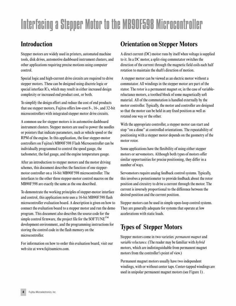
IntroductionStepper motors are widely used in printers, automated machine tools, disk drives, automotive dashboard instrument clusters, and other applications requiring precise motions using computer control.
Special logic and high-current drive circuits are required to drive stepper motors. These can be designed using discrete logic or special interface ICs, which may result in either increased design complexity or increased end product cost, or both.
To simplify the design effort and reduce the cost of end products that use stepper motors, Fujitsu offers low-cost 8-, 16-, and 32-bit microcontrollers with integrated stepper motor drive circuits.
A common use for stepper motors is in automotive dashboard instrument clusters. Stepper motors are used to power the needles or pointers that indicate parameters, such as vehicle speed or the RPM of the engine. In this application, the four stepper-motor controllers on Fujitsu’s MB90F598 Flash Microcontroller can be individually programmed to control the speed gauge, the tachometer, the fuel gauge, and the engine temperature gauge.
After an introduction to stepper motors and the motor driving schemes, this document describes the function of one stepper-motor controller on a 16-bit MB90F598 microcontroller. The interfaces to the other three stepper-motor control macros on the MB90F598 are exactly the same as the one described.
To demonstrate the working principles of stepper-motor interface and control, this application note uses a 16-bit MB90F598 flash microcontroller evaluation board. A description is given on how to connect the evaluation board to a stepper motor and run the demo program. This document also describes the source code for the simple control firmware, the project file for the SOFTUNE™ development environment, and the programming instructions for storing the control code in the flash memory on the microcontroller.
For information on how to order this evaluation board, visit our web site at www.fujitsumicro.com.
Orientation on Stepper MotorsA direct current (DC) motor runs by itself when voltage is supplied to it. In a DC motor, a split-ring commutator switches the direction of the current through the magnetic field coils each half rotation to maintain the shaft’s direction of motion.
A stepper motor can be viewed as an electric motor without a commutator. All windings in the stepper motor are part of the stator. The rotor is a permanent magnet or, in the case of variable-reluctance motors, a toothed block of some magnetically soft material. All of the commutation is handled externally by the motor controller. Typically, the motor and controller are designed so that the motor can be held in any fixed position as well as rotated one way or the other.
With the appropriate controller, a stepper motor can start and stop “on a dime” at controlled orientations. The repeatability of positioning with a stepper motor depends on the geometry of the motor rotor.
Some applications have the flexibility of using either stepper motors or servomotors. Although both types of motors offer similar opportunities for precise positioning, they differ in a number of ways.
Servomotors require analog feedback control systems. Typically, this involves a potentiometer to provide feedback about the rotor position and circuitry to drive a current through the motor. The current is inversely proportional to the difference between the desired position and the current position.
Stepper motors can be used in simple open-loop control systems. They are generally adequate for systems that operate at low accelerations with static loads.
Types of Stepper MotorsStepper motors come in two varieties: permanent magnet and variable reluctance. (The reader may be familiar with hybrid motors, which are indistinguishable from permanent magnet motors from the controller's point of view.)
Permanent magnet motors usually have two independent windings, with or without center taps. Center-tapped windings are used in unipolar permanent magnet motors (see Figure 1) .

Application Note
Fujitsu Microelectronics, Inc. 5
Figure 1. Unipolar Permanent Magnet Motors
Bipolar permanent magnet and hybrid motors are constructed with a mechanism similar to that used in unipolar motors, except that the two windings are wired without center taps (see Figure 2). The motor itself is simpler, but the drive circuitry needed to reverse the polarity of each pair of motor poles is more complex.
Figure 2. Bipolar Permanent Magnet and Hybrid Motors
Stepper motors come in a wide range of angular resolutions. The coarsest motors typically turn 90 degrees per step, whereas high-resolution permanent-magnet motors can commonly handle 1.8 or even 0.72 degrees per step. With the appropriate controller, most permanent magnet and hybrid motors can be run in half steps, and some controllers can handle smaller fractional steps or microsteps.
For permanent magnet and variable-reluctance stepper motors, when one winding of the motor is energized, the rotor (under no load) snaps to a fixed angle. It holds that angle until the torque
exceeds the holding torque of the motor, at which point the rotor turns, trying to hold at each successive equilibrium point.
Driving Scheme for a Bipolar Stepper MotorAn electrical drive is required to properly control a bipolar stepper motor. Its functions include start, stop, reverse, and velocity changes. Stepper motors translate digital switching sequences into motion. The driving magnetic field “rotates” as magnetic coils are switched on and off. This pushes and pulls at permanent magnets arranged around the edge of a rotor that drives the output shaft.
The drive circuitry for a bipolar stepper motor requires an H-bridge control circuit for each winding. An H-bridge allows the polarity of the power applied to each end of each winding to be controlled independently. Figure 3 shows the control sequences for single stepping such a motor.
Figure 3. Control Sequences forHalf Stepping a Bipolar Stepper Motor
1N
2
S1
2
SN
SN
S
N
1
a b
2
a b
1N
2
S1
2
SN
SN
S
N1a 1b
2a 2b
1a 1b
2a 2b
++
+
--
-
- --
--
--
--
--
----
++
+-
Index12345678
1a+---+--
1b 2a 2bClockwise Rotation
Interfacing a Stepper Motor to the MB90F598 Microcontroller
6 Fujitsu Microelectronics, Inc.
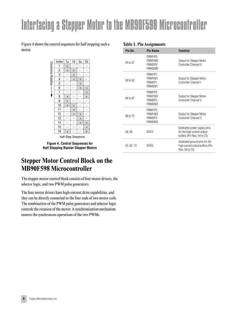
Figure 4 shows the control sequences for half stepping such a motor.
Figure 4. Control Sequences forHalf Stepping Bipolar Stepper Motors
Stepper Motor Control Block on the MB90F598 MicrocontrollerThe stepper-motor control block consists of four motor drivers, the selector logic, and two PWM pulse generators.
The four motor drivers have high-current drive capabilities, and they can be directly connected to the four ends of two motor coils. The combination of the PWM pulse generators and selector logic controls the rotation of the motor. A synchronization mechanism ensures the synchronous operations of the two PWMs.
Table 1. Pin Assignments
+-
-
--
-
- --
++
-+
++
-+
+---
--
++
Index12345678
1a++-----
1b 2a 2b
+-
-
--
-
- --
++
-+
++
-+
+---
--
++
910111213141516
++-----
Clockwise Rotation
Half-Step Sequence
Pin No. Pin Name Function
54 to 57
PWM1P0PWM1M0PWM2P0PWM2M0
Output for Stepper Motor Controller Channel 0
59 to 62
PWM1P1PWM1M1PWM2P1PWM2M1
Output for Stepper Motor Controller Channel 1
64 to 67
PWM1P2PWM1M2PWM2P2PWM2M2
Output for Stepper Motor Controller Channel 2
69 to 72
PWM1P3PWM1M3PWM2P3PWM2M3
Output for Stepper Motor Controller Channel 3
58, 68 DVCCDedicated power supply pins for the high current output buffers (Pin Nos. 54 to 72)
53, 63, 73 DVSSDedicated ground pins for the high current output buffers (Pin Nos. 54 to 72)
Application Note
Fujitsu Microelectronics, Inc. 7
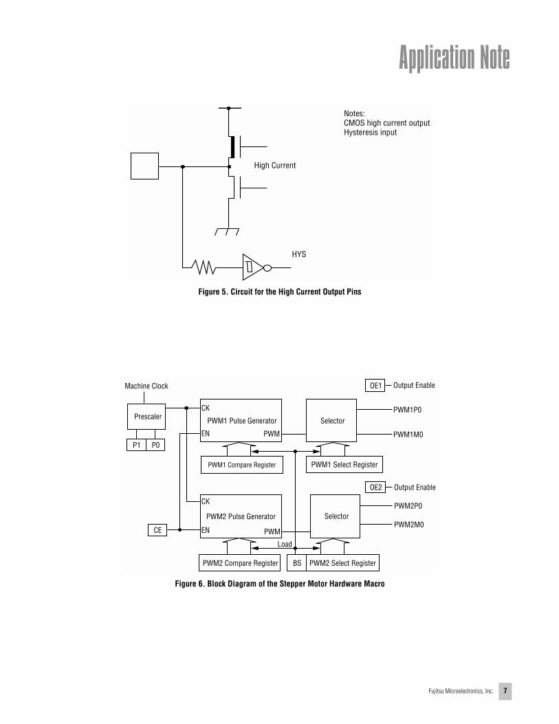
Figure 5. Circuit for the High Current Output Pins
Figure 6. Block Diagram of the Stepper Motor Hardware Macro
High Current
HYS
Notes:CMOS high current outputHysteresis input
Machine Clock
Prescaler
P1 P0
CE
CK
EN
PWM1 Pulse Generator
PWM
PWM1 Compare Register
CK
EN PWM
PWM2 Pulse Generator
PWM2 Compare Register BS
Load
PWM2 Select Register
Selector
PWM1 Select Register
SelectorPWM1P0
PWM1M0
OE2 Output Enable
Output Enable
PWM2P0
PWM2M0
OE1

Interfacing a Stepper Motor to the MB90F598 Microcontroller
8 Fujitsu Microelectronics, Inc.
Register Details for the Stepper Motor Control Hardware Block
[bit 7] OE2: Output enable bitWhen this bit is set to “1”, the external pins are assigned as PWM2P0 and PWM2M0 outputs. Otherwise the pins can be used as general purpose I/O.
[bit 6] OE1: Output enable bitWhen this bit is set to “1”, the external pins are assigned as PWM1P0 and PWM1M0 outputs. Otherwise the pins can be used as general purpose I/O.
[bits 5 to 4] P1 to P0: Operation clock select bitsThese bits specify the clock input signal for the PWM pulse generators.
Table 2. Operation Clock Select Bits
[bit 3] CE: Count enable bitThis bit enables the operation of the PWM pulse generators. When it is set to “1”, the PWM pulse generators start their operation. Note that the PWM2 pulse generator starts the operation one machine clock cycle after the PWM1 pulse generator is started. This is to help reduce the switching noise from the output drivers.
P1 P0 Clock Input
0 0 Machine clock
0 1 1/2 machine clock
1 0 1/4 machine clock
1 1 1/8 machine clock
(1) PWM Control 0 Register
PWM Control 0 RegisterAddress: 00005Eh
Read/WriteInitial Value
7
OE2
(R/W)(0)
OE1
6
(R/W)(0)
5
P1
(R/W)(0)
4
P0
(R/W)(0)
3
CE
(R/W)(0)
2 1 0
(R/W)(0)
TST
Bit Number
PWC0
Application Note
Fujitsu Microelectronics, Inc. 9
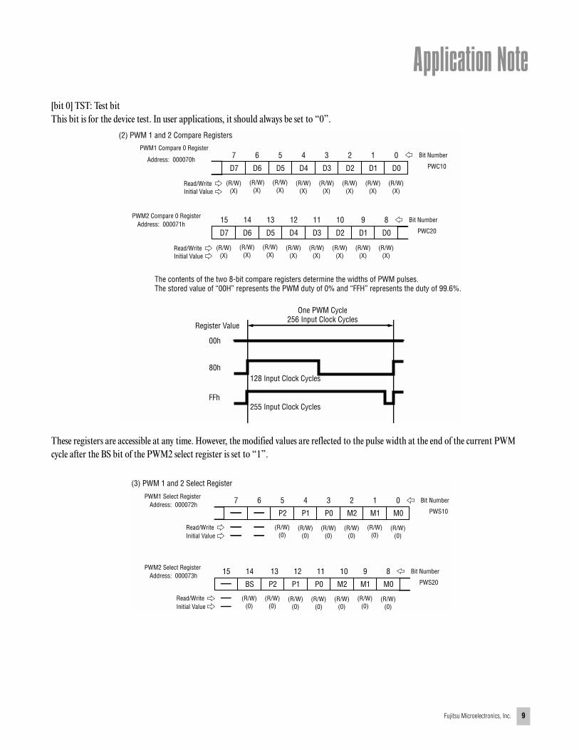
[bit 0] TST: Test bitThis bit is for the device test. In user applications, it should always be set to “0”.
These registers are accessible at any time. However, the modified values are reflected to the pulse width at the end of the current PWM cycle after the BS bit of the PWM2 select register is set to “1”.
PWM1 Compare 0 Register
Address: 000070h
Read/WriteInitial Value
7
D7
(R/W)(X)
D6
6
(R/W)(X)
5
D5
(R/W)(X)
4
D4
(R/W)(X)
3
D3
(R/W)(X)
D2
(R/W)(X)
2
D1
(R/W)(X)
1 0
(R/W)(X)
D0
Bit Number
PWC10
PWM2 Compare 0 RegisterAddress: 000071h
Read/WriteInitial Value
15
D7
(R/W)(X)
D6
14
(R/W)(X)
13
D5
(R/W)(X)
12
D4
(R/W)(X)
11
D3
(R/W)(X)
D2
(R/W)(X)
10
D1
(R/W)(X)
9 8
(R/W)(X)
D0
Bit Number
PWC20
Register Value
00h
80h
FFh
One PWM Cycle256 Input Clock Cycles
255 Input Clock Cycles
128 Input Clock Cycles
(2) PWM 1 and 2 Compare Registers
The contents of the two 8-bit compare registers determine the widths of PWM pulses.The stored value of “00H” represents the PWM duty of 0% and “FFH” represents the duty of 99.6%.
(3) PWM 1 and 2 Select Register
PWM1 Select RegisterAddress: 000072h
Read/WriteInitial Value
7
(R/W)(0)
6
(R/W)(0)
5
P2
(R/W)(0)
4
P1
(R/W)(0)
3
P0 M2 M1 M0
(R/W)(0)
2 1 0
(R/W)(0)
Bit Number
PWS10
PWM2 Select RegisterAddress: 000073h
Read/WriteInitial Value
15
(R/W)(0)
14
(R/W)(0)
13
P2BS
(R/W)(0)
(R/W)(0)
12
P1
(R/W)(0)
11
P0 M2 M1 M0
(R/W)(0)
10 9 8
(R/W)(0)
Bit Number
PWS20

Interfacing a Stepper Motor to the MB90F598 Microcontroller
10 Fujitsu Microelectronics, Inc.
[bit 14] BS: Update bitThis bit is set to synchronize the settings for the PWM outputs. Any modifications in the two compare registers and two select registers are not reflected at the output signals until this bit is set. When this bit is set to “1”, the PWM pulse generators and selectors load the register contents at the end of the current PWM cycle. The BS bit is reset to “0” automatically at the beginning of the next PWM cycle. If the BS bit is set to “1” by software at the same time as this automatic reset, the BS bit is set to “1” (or remains unchanged) but the automatic reset is cancelled.
[bits 13 to 11] P2 to P0: Output Select bitsThese bits select the output signal at PWM2P0.
[bits 10 to 8] M2 to M0: Output Select bitsThese bits select the output signal at PWM2M0.
[bits 5 to 3] P2 to P0: Output Select bitsThese bits select the output signal at PWM1P0.
[bits 2 to 0] M2 to M0: Output Select bitsThese bits select the output signal at PWM1M0.
Table 3 shows the relationship between output levels and select bits.
Table 3. Output Select Bits
Description of FirmwareThe following describes software control for the physical movement of the stepper-motor rotor using parameters local to the software application.
Varying the step size of the output signals controls the speed of the stepper motor. Different step sizes can be programmed by loading different values into the “compare registers”. Care should be taken to slow the rotor down before the desired position is reached. This is demonstrated in the source code.
The application is set up so that the reload-timer interrupt service routine is used to update the position of the stepper motor. The ISR programs the “compare registers” and then sets the “output-enable” bits in the “control register” to drive the external pins.
The value for the time period of the reload-timer interrupt is chosen so that smooth movement is achieved.
The following code illustrates position control by setting the required parameters in the control program:
// Control the rotor of one of the stepper motors
void TestStepperMotor_0 (void)
{
unsigned long ctr;
unsigned long ctr2;
DDR4_D40 = 1;
PDR4_P40 = 1;
DDR4_D47 = 1;
PDR4_P47 = 0;
uiMaxSpeed = 1; // Controls the speed of the motor
for(ctr = 500000L; ctr; ctr--);
uiRequiredPosition = MAX_STEPS; // MAX_STEPS is
the maximum no. of
// steps the motor can move in
// either direction
for(ctr = 700000L; ctr; ctr--);
uiRequiredPosition = 0;
while (uiCurrentPosition != uiRequiredPosition);
for(ctr = 700000L; ctr; ctr--);
uiRequiredPosition = 1000;
P2 P1 P0 PWMnP0
0 0 0 L
0 0 1 H
0 1 X PWM pulses
1 X X High impedance
M2 M1 M0 PWMnM0
0 0 0 L
0 0 1 H
0 1 X PWM pulses
1 X X High impedance
Application Note
Fujitsu Microelectronics, Inc. 11
while (uiCurrentPosition != uiRequiredPosition);
for(ctr = 700000L; ctr; ctr--);
uiRequiredPosition = 2000;
while(uiCurrentPosition != uiRequiredPosition);
for(ctr = 700000L; ctr; ctr--);
uiRequiredPosition = 1500;
while(uiCurrentPosition != uiRequiredPosition);
for(ctr = 700000L; ctr; ctr--);
uiRequiredPosition = 500;
while(uiCurrentPosition != uiRequiredPosition);
for(ctr = 700000L; ctr; ctr--);
while (0);
}
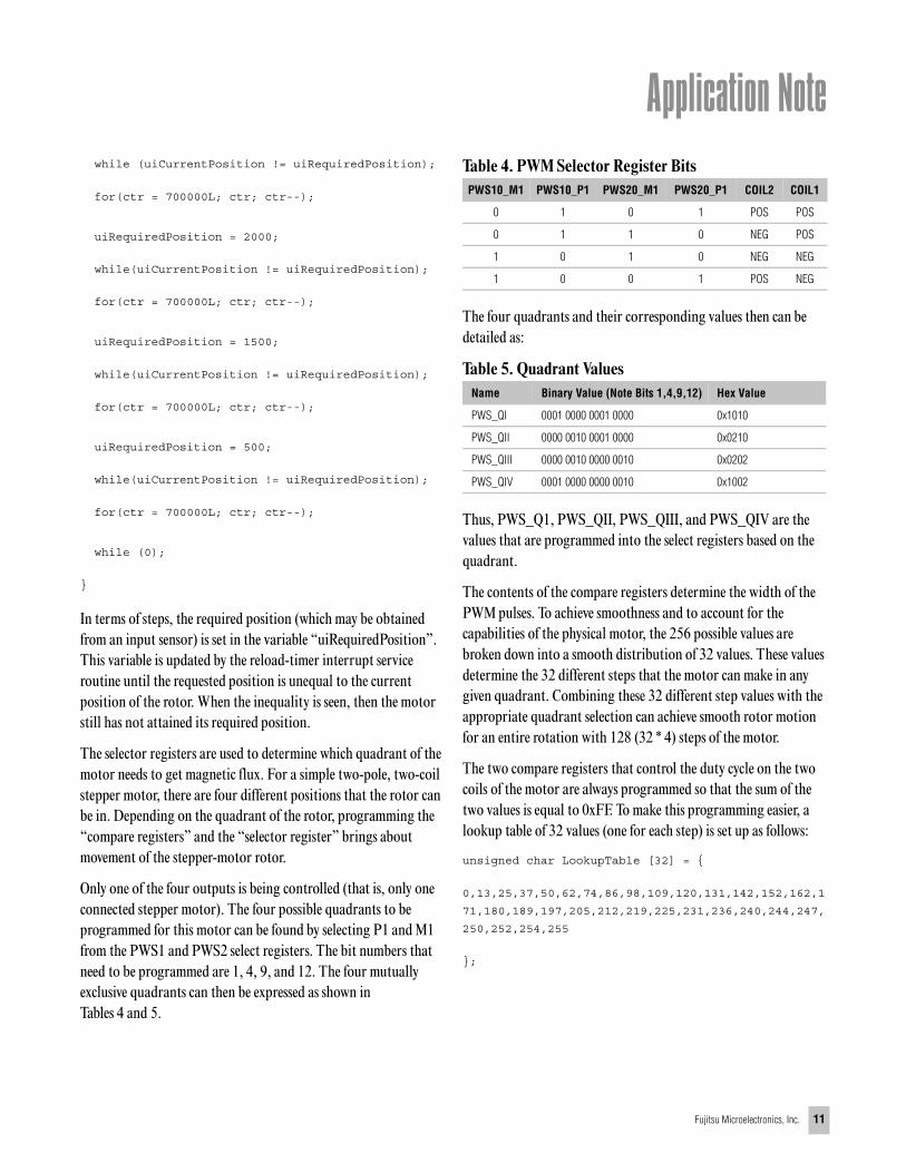
In terms of steps, the required position (which may be obtained from an input sensor) is set in the variable “uiRequiredPosition”. This variable is updated by the reload-timer interrupt service routine until the requested position is unequal to the current position of the rotor. When the inequality is seen, then the motor still has not attained its required position.
The selector registers are used to determine which quadrant of the motor needs to get magnetic flux. For a simple two-pole, two-coil stepper motor, there are four different positions that the rotor can be in. Depending on the quadrant of the rotor, programming the “compare registers” and the “selector register” brings about movement of the stepper-motor rotor.
Only one of the four outputs is being controlled (that is, only one connected stepper motor). The four possible quadrants to be programmed for this motor can be found by selecting P1 and M1 from the PWS1 and PWS2 select registers. The bit numbers that need to be programmed are 1, 4, 9, and 12. The four mutually exclusive quadrants can then be expressed as shown in Tables 4 and 5.
Table 4. PWM Selector Register Bits
The four quadrants and their corresponding values then can be detailed as:
Table 5. Quadrant Values
Thus, PWS_Q1, PWS_QII, PWS_QIII, and PWS_QIV are the values that are programmed into the select registers based on the quadrant.
The contents of the compare registers determine the width of the PWM pulses. To achieve smoothness and to account for the capabilities of the physical motor, the 256 possible values are broken down into a smooth distribution of 32 values. These values determine the 32 different steps that the motor can make in any given quadrant. Combining these 32 different step values with the appropriate quadrant selection can achieve smooth rotor motion for an entire rotation with 128 (32 * 4) steps of the motor.
The two compare registers that control the duty cycle on the two coils of the motor are always programmed so that the sum of the two values is equal to 0xFF. To make this programming easier, a lookup table of 32 values (one for each step) is set up as follows:
unsigned char LookupTable [32] = {
0,13,25,37,50,62,74,86,98,109,120,131,142,152,162,1
71,180,189,197,205,212,219,225,231,236,240,244,247,
250,252,254,255
};
PWS10_M1 PWS10_P1 PWS20_M1 PWS20_P1 COIL2 COIL1
0 1 0 1 POS POS
0 1 1 0 NEG POS
1 0 1 0 NEG NEG
1 0 0 1 POS NEG
Name Binary Value (Note Bits 1,4,9,12) Hex Value
PWS_QI 0001 0000 0001 0000 0x1010
PWS_QII 0000 0010 0001 0000 0x0210
PWS_QIII 0000 0010 0000 0010 0x0202
PWS_QIV 0001 0000 0000 0010 0x1002

Interfacing a Stepper Motor to the MB90F598 Microcontroller
12 Fujitsu Microelectronics, Inc.
Thus, in pseudo-code the programming of the compare and select registers for the first quadrant would look like:
TableIndex = PositionDesired & 0x1F; // 2 to the
power 5 = 32 steps per quadrant
CompareRegister_1 = LookupTable [ TableIn-
dex ];
CompareRegister_2 = LookupTable [ 32 – TableIndex
];
SelectRegister = PWS_QI; // 1’st Quadrant
means coil_1 is Pos and coil_2 is Pos
// See Table 4 and 5
The maximum speed that a stepper motor can attain is determined by the physical properties of the motor. The motor speed is controlled by varying the step size (that is, by varying the duty cycle in the compare registers). Larger step values make the rotor travel faster and farther. The value of the compare registers needs to be controlled carefully to bring the speed of the motor down smoothly when the desired position is being approached.
Thus, the offset that the rotor is allowed to move from the current position towards the required position controls the speed. The offset to be added (or subtracted) from the current offset is a function of the difference between the current position and the required position.
For the motor to achieve a desired speed, a condition such as the following needs to be employed:
If( (RequiredPosition_0-CurrentPosition_0) >
CurrentOffset_0) {
// We can speed up the motor
CurrentOffset ++;
}
.
.
.
CurrentPosition_0 = CurrentPosition_0 + CurrentOff-
set;
.
.
ProgramCompareAndSelectRegisters ();
Similarly, when the required position is being reached or when the maximum offset is being reached, the speed needs to be reduced and consequently, the CurrentOffset needs to be decreased.
The motion of the rotor can be set in both clockwise and counterclockwise directions. The appropriate checks need to be in place for the rotor to correctly turn.

Application Note
Fujitsu Microelectronics, Inc. 13
Figure 7. Program Flow Chart
Required Items for Running the Sample Code and Demo1. FLASH-CAN2 Board, Part No. FLASHCAN2-100MP-M062. MB90F598 Microcontroller (included in the evaluation kit)3. Stepper motor 4. Connecting wires5. Serial cable6. PC or laptop running SOFTUNE V3.07. Application code8. Flash download utility (also on CDROM) called FLASH361.EXE9. Power supply for the FLASH-CAN2 Board and also for providing high current inputs required for driving the stepper motor
Select which quadrant of themotor we are dealing with
Select duty cycles for the two coilsSet the polarities for the coils
Check position
Check speed
Decrease speed by 1
Increase speed by 1
End
Update
Has therequired positionbeen reached?
Is speedgreater than
1?
Can speedbe increased?
Is speed less than maximum speed allowed?
Is speed more than theoffset between the
current position andthe required
position?
Yes
No
No
Yes
Yes
No
Interfacing a Stepper Motor to the MB90F598 Microcontroller
14 Fujitsu Microelectronics, Inc.
Connecting a Stepper Motor to the FLASH-CAN2 Board with an MB90F598The FLASH-CAN2 evaluation board makes all the MB90F598 pins accessible through four rows of external connectors. These external connectors make it easy to connect stepper motors to the board for control by the MB90F598. For more details, refer to the user manual for the evaluation board.
To connect a stepper motor to the first stepper-motor controller pins:
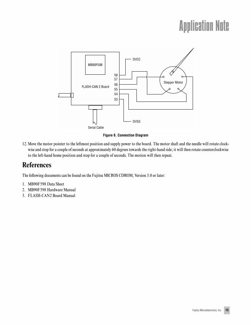
1. Connect Pins 53 and 58 to DVSS and DVCC, respectively. A high current input source is required to provide the drive current to the motors (see Table 1).
2. Connect Pins 54, 55, 56, and 57 across the two coils of the two-coil stepper motor (see Table 1). Make these connections accu-rately. Wrong connections here may produce extreme vibrations and possibly cause physical damage to the motor.
The complete instructions for downloading and running the demo application are:
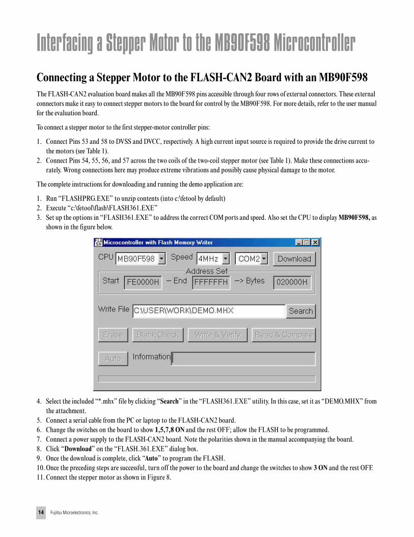
1. Run “FLASHPRG.EXE” to unzip contents (into c:\fetool by default)2. Execute “c:\fetool\flash\FLASH361.EXE”3. Set up the options in “FLASH361.EXE” to address the correct COM ports and speed. Also set the CPU to display MB90F598, as
shown in the figure below.
4. Select the included “*.mhx” file by clicking “Search” in the “FLASH361.EXE” utility. In this case, set it as “DEMO.MHX” from the attachment.
5. Connect a serial cable from the PC or laptop to the FLASH-CAN2 board.6. Change the switches on the board to show 1,5,7,8 ON and the rest OFF; allow the FLASH to be programmed.7. Connect a power supply to the FLASH-CAN2 board. Note the polarities shown in the manual accompanying the board.8. Click “Download” on the “FLASH.361.EXE” dialog box.9. Once the download is complete, click “Auto” to program the FLASH.10. Once the preceding steps are successful, turn off the power to the board and change the switches to show 3 ON and the rest OFF.11. Connect the stepper motor as shown in Figure 8.
Application Note
Fujitsu Microelectronics, Inc. 15
Figure 8. Connection Diagram
12. Move the motor pointer to the leftmost position and supply power to the board. The motor shaft and the needle will rotate clock-wise and stop for a couple of seconds at approximately 60 degrees towards the right-hand side; it will then rotate counterclockwise to the left-hand home position and stop for a couple of seconds. The motion will then repeat.
ReferencesThe following documents can be found on the Fujitsu MICROS CDROM, Version 3.0 or later:
1. MB90F598 Data Sheet2. MB90F598 Hardware Manual3. FLASH-CAN2 Board Manual
DVCC
MB90F598
5857
565554
53
Serial Cable
DVSS
FLASH-CAN 2 BoardStepper Motor
FUJITSU MICROELECTRONICS AMERICA, INC.Corporate Headquarters1250 East Arques Avenue, Sunnyvale, California 94088-3470Tel: (800) 866-8608 Fax: (408) 737-5999E-mail: [email protected] Internet: http://www.fma.fujitsu.com
©2000 Fujitsu Microelectronics, Inc.; Fujitsu Limited; Fujitsu Mikroelektronik GmbH; and FujitsuMicroelectronics Ltd. All rights reserved.
All company and product names are trademarks orregistered trademarks of their respective owners.
With respect to any information contained in thisdocument, Fujitsu makes no warranties, express,implied or otherwise, including but not limited towarranty of merchantability or of fitness for aparticular purpose, or warranty that such informationshall be free from errors or that such errors shall be corrected, or warranty that such information shall be free from infringement or patents, patentapplications, copyrights, semiconductor chipprotection rights, trade secrets and other proprietaryor legal rights of a third party. In no event will Fujitsube responsible for any incidental or consequentialdamages arising out of use of this information.
The information in this document does not conveyany license under the copyrights, patent rights, or trademarks claimed and owned by Fujitsu Limited,its subsidiaries, or Fujitsu Microelectronics, Inc.
Fujitsu Microelectronics, Inc. reserves the right tochange products or specifications without notice.
No part of this publication may be copied or repro-duced in any form, or by any means, or transferred to any third party without prior written consent ofFujitsu Microelectronics, Inc.
Printed in U.S.A. EC-AN-20837-02/2000


![Stepper Motor Drivers...Bipolar stepper motor drivers Part number Interface Ratings Stepping mode ADMD ACDS AGC Temperature range T A [ C] Package Clock Phase Serial VM (opr) [V] IOUT](https://img.pdfslide.us/doc/110x75/6126ddeca0aae927511bded5/stepper-motor-drivers-bipolar-stepper-motor-drivers-part-number-interface-ratings.jpg)