Embed Size (px)
Citation preview
APPLICATION NOTE
USING THE L6204, A BIPOLAR STEPPER ANDDC MOTOR DRIVER IN BCD TECHNOLOGY
by E Balboni
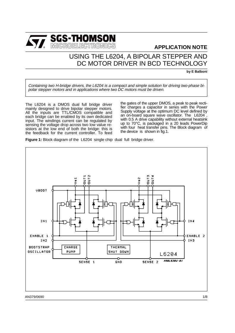
The L6204 is a DMOS dual full bridge drivermainly designed to drive bipolar stepper motors.All the inputs are TTL/CMOS compatible andeach bridge can be enabled by its own dedicatedinput. The windings current can be regulated bysensing the voltage drop across two low value re-sistors at the low end of both the bridge: this isthe feedback for the current controller. To feed
the gates of the upper DMOS, a peak to peak recti-fier charges a capacitor in series with the PowerSupply voltage at the optimum DC level defined byan on-board square wave oscillator. The L6204 ,with 0.5 A drive capability without external heatsinkup to 70°C, is packaged in a 20 leads PowerDipwith four heat transfer pins. The Block diagram ofthe device is shown in fig.1.
AN379/0690
Figure 1: Block diagram of the L6204 single chip dual full bridge driver.
Containing two H-bridge drivers, the L6204 is a compact and simple solution for driving two-phase bi-polar stepper motors and in applications where two DC motors must be driven.
1/8

This is achieved by the configuration shown infig.3A. The two independent motors (A and B)can be controlled by only one controller (L6506).The sensing resistor (RsA, RsB) generates a volt-age proportional to the motor current, that is thefeedback for the current control loop. A secondloop, not shown in figure, can control the speedstability while the direction is defined by the Inputstate of the L6506. The Enable Input (ENA, ENB)can inhibit one motor or the other while the PowerEnable acts on both at the same time. D1 and D2(BAT41 or equivalent), C3 and C4, generates thebootstrap voltage by rectifiing the wave availableat pin. 11 of the L6204. When more than onedriver is used at the same Supply Voltage on acommon Printed Circuit Board, the bootstrap volt-age can be generated only by one of them (mas-ter) and used to supply all the other L6204(slaves) saving diodes and capacitors. R1 C1 (R2
C2) is a snubber network that must be closelyconnected to the output pins and its use is recom-mended in all the application circuits using theL6204. The values can be calculated as it follows:R = Vs/Ip and C = Ip/(dV/dt), where Vs is themaximum Supply Voltage of the Application, Ip isthe peak of the load current and dV/dt is the SlewRate accepted as the optimum compromise be-tween speed and transient generation/radiation(SR of 200 V/µS are commonly chosen). The net-work R5C5 sets the operating frequency accord-ing to f = 1/(0.69 R5C5) for R5 ≥ 10Kohm. R3and R4 are used to protect the comparator inputinside the L6506 against possible negative transi-tions across the sensing resistor RsA or RsB. TheL6204 can be used with paralleled inputs and out-puts to double the current capability of the singlebridge; for an optimized solution, however, 1.6times the nominal current is recommended in-
GENERAL APPLICATIONS HINTSThe L6204 can be used in a very wide range ofapplications such as the drive of lamps, sole-noids, DC motors or any other inductive loads.The drive of different loads in single-ended con-figuration is shown in fig.2. The current in theLoad Z1, that may be a DC motor, can flow inboth the directions but its peak amplitude cannotbe controlled. By means of a change of the Duty
Cycle of the input signal it is possible to vary inOpen Loop Mode the steady state speed of theDC motor: this is possible because the averagecurrent in the winding is dependent from the DutyCycle. The L/R ratio must be a few times shorterthan the minimum DC. In a similar way it can bedimmed a lamp connected to the supply (Z2) or toground (Z3). Very often, when a DC motor isdriven, peak current and speed must be boothcontrolled in a Closed Loop Mode.
Figure 2: The L6204 is not intended only for Bipolar Stepper applications: here above three different driverconfigurations are shown. Z1 is a DC motor to be driven in both CW and CCW direction. Z2 canbe solenoid like a relay or hammer. Z3 can be an alogen lamp which light intensity is controlledby variable Duty Cycle.
APPLICATION NOTE
2/8

stead of two. This configuration is shown in fig.2to drive the load Z1. A more complex circuit, inwich one paralleled L6204 drives a DC motor, isshown in fig.3B; in this example the two chopperof the L6506 are used to implement two func-tions: 1) Current Control during speed variationat Ip max = 0.8A and 2) Current Control duringbrake and/or direction change at higher currentlevel that depends from the brake repetition (it
must be in the Max Ratings limit). The dividerR6R7 defines the brake current intensity asV17/Rs while the product (Ip max.) x ( Rs) is thelimit of the reference voltage V16 for speed con-trol. The Enable function is driven via the L6506 .Since during the brake time the Enable of theL6506 is chopped, the motor current ricirculatesvia the Supply; because of this a suitable largecapacitor must be connected in parallel to C2.
Figure 3A: Bidirectional DC motor drive. The L6204 can drive two motors.
APPLICATION NOTE
3/8

Stepping Motor DrivingThe drive of one stepping motor is shown in fig.4,where the controller L297 generates the re-quested signals to drive the motor in Half-StepMode or in Full Step Mode.The rotation speed or step change is controlledby a clock signal or a single clock pulse at pin.18(CK). The Mode depends from the logical state of
the H / F input while the state of the CW/CCW in-put defines the direction of the rotation. Depend-ing on the numbered state, odd or even, of an in-ternal clock pulse at the moment at wich theFull-Step Mode is selected, the motor is drivenwith two-phases-on or with one-phase-on respec-tively. An open collector output (home) indicatesthe translator state 0101 that occurs only duringan odd numbered state of the internal clock.
Figure 3B: Bidirectional DC motor drive. The L6204 can drive the motor in a paralleled configuration whilethe L6506 provides the peak current control both during normal rotation and during brakingtime.
APPLICATION NOTE
4/8

This last is obtained from the oscillator the fre-quency of which is fixed by the ratio 1/0.69 R5C5about (R5 ≥ 10Kohm). The peak of the choppedcurrent is given by the ratio of the reference volt-age at pin.15 and the value of the sensing resis-
tors Rs. When the four phase signals needed atthe inputs of the L6204 are generated in anyother way than by the L297 (for example, viaµProcessor), the motor driver needs one interfaceto control the peak current. One possible solutionis shown in fig.5.
Figure 4: Bipolar stepping motor drive: phase sequence generation and current peak control are achievedby means of the controller L297.
APPLICATION NOTE
5/8

The motor can be driven in the Full-Step or inHalf-Step Mode. The chopped current Ip is con-trolled at the value Vref/Rs where Vref is the out-put voltage of the divider R6 R7. The pins 16and 17 (reference input voltage of the controller)
can be driven with two different signals. This ar-rangement allows to keep constant the motor cur-rent and the torque during the Half-Step Moderevolution of the stepper. This behavior is well ex-plained by the fig. 6.
Figure 5: The L6506 can be used to control the peak current in the windings of a bipolar stepper motor.The power is supplied by the L6204.
APPLICATION NOTE
6/8
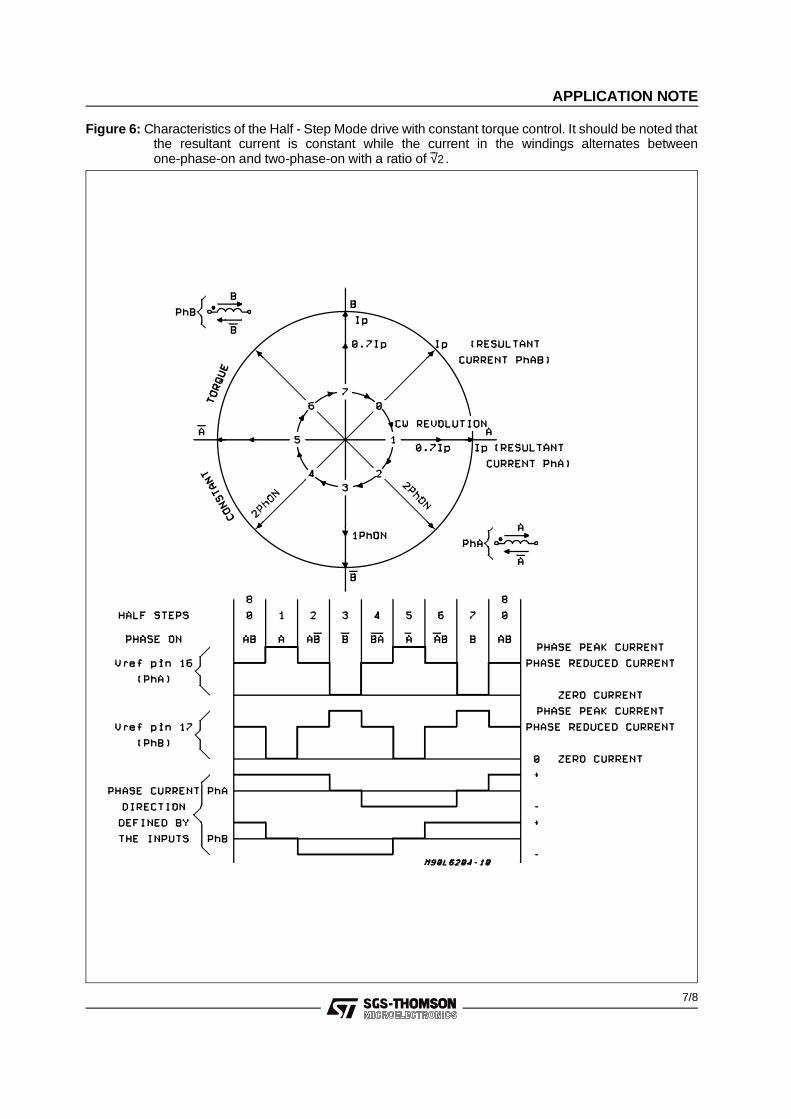
Figure 6: Characteristics of the Half - Step Mode drive with constant torque control. It should be noted thatthe resultant current is constant while the current in the windings alternates betweenone-phase-on and two-phase-on with a ratio of √2 .
APPLICATION NOTE
7/8

Information furnished is believed to be accurate and reliable. However, SGS-THOMSON Microelectronics assumes no responsibility for theconsequences of use of such information nor for any infringement of patents or other rights of third parties which may result from its use. Nolicense is granted by implication or otherwise under any patent or patent rights of SGS-THOMSON Microelectronics. Specifications men-tioned in this publication are subject to change without notice. This publication supersedes and replaces all information previously supplied.SGS-THOMSON Microelectronics products are not authorized for use as critical components in life support devices or systems without ex-press written approval of SGS-THOMSON Microelectronics.
© 1995 SGS-THOMSON Microelectronics - All Rights Reserved
SGS-THOMSON Microelectronics GROUP OF COMPANIESAustralia - Brazil - France - Germany - Hong Kong - Italy - Japan - Korea - Malaysia - Malta - Morocco - The Netherlands - Singapore -
Spain - Sweden - Switzerland - Taiwan - Thaliand - United Kingdom - U.S.A.
APPLICATION NOTE
8/8