Embed Size (px)
Citation preview
INTERFACE FRACTURE TOUGHNESS
S.V. Kamat
Defence Metallurgical Research Laboratory
Hyderabad
Workshop on Mechanical Behaviour at Small Length Scales-IV
24-27th February, 2013
OUTLINE
DMRL
• Introduction
• Stresses in thin films
• Interface fracture mechanics
• Experimental techniques for measurement of interface fracture
toughness
INTRODUCTION
• There are several systems and technologies that use materials in
film form to achieve both their structural and functional
requirements
– Microelectronic Integrated Circuits
– Magnetic Information Storage Systems
– Microelectromechanical Systems (MEMS)
– Coatings for Thermal, Oxidation, Corrosion and Wear
Resistance
DMRL
• The characterization of the mechanical properties of the individual
constituents (thin films) as well as that of the interfaces are critical
for designing as well as ensuring reliability of these systems
• In this talk the focus will be on interface fracture
STRESSES IN THIN FILMS
• Stresses in films and multilayers have three primary origins:
Intrinsic
thermal
mechanical
DMRL
• Intrinsic stresses arise during the deposition process.
Intrinsic stresses are distinct from thermal stresses in that they are the
stresses present at the deposition temperature.
The mechanisms which generate intrinsic stresses include grain
growth, defect annihilation, phase transition and evaporation of a
solvent
• Thermal stresses arise due to changes in temperature when the film and
substrate (or the layers in a multilayer) have different coefficients of thermal
expansion (CTE).
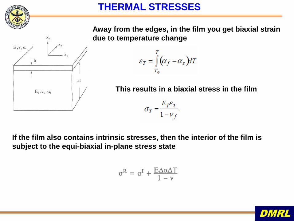
THERMAL STRESSES
DMRL
If the film also contains intrinsic stresses, then the interior of the film is
subject to the equi-biaxial in-plane stress state
Away from the edges, in the film you get biaxial strain
due to temperature change
This results in a biaxial stress in the film
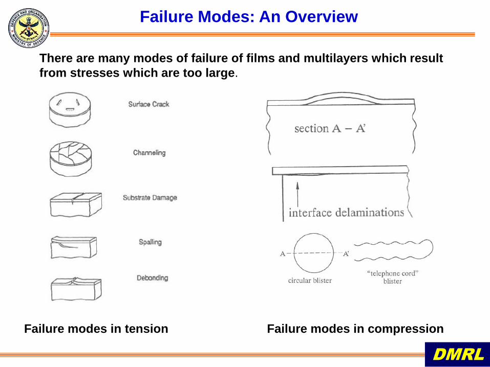
Failure Modes: An Overview
There are many modes of failure of films and multilayers which result
from stresses which are too large.
DMRL
Failure modes in tension Failure modes in compression
INTERFACIAL FRACTURE MECHANICS
DMRL
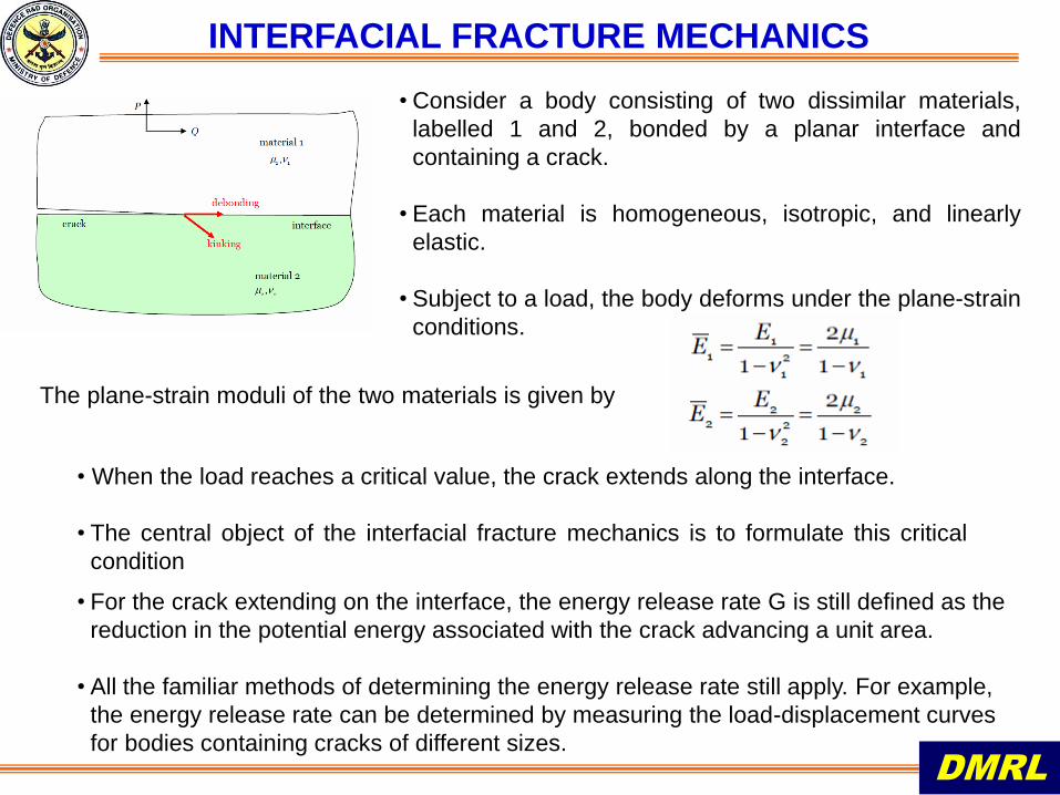
• Consider a body consisting of two dissimilar materials,
labelled 1 and 2, bonded by a planar interface and
containing a crack.
• Each material is homogeneous, isotropic, and linearly
elastic.
• Subject to a load, the body deforms under the plane-strain
conditions.
• When the load reaches a critical value, the crack extends along the interface.
• The central object of the interfacial fracture mechanics is to formulate this critical
condition
• For the crack extending on the interface, the energy release rate G is still defined as the
reduction in the potential energy associated with the crack advancing a unit area.
• All the familiar methods of determining the energy release rate still apply. For example,
the energy release rate can be determined by measuring the load-displacement curves
for bodies containing cracks of different sizes.
The plane-strain moduli of the two materials is given by
INTERFACIAL FRACTURE MECHANICS
DMRL
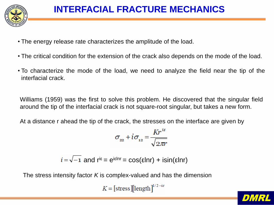
Williams (1959) was the first to solve this problem. He discovered that the singular field
around the tip of the interfacial crack is not square-root singular, but takes a new form.
At a distance r ahead the tip of the crack, the stresses on the interface are given by
• The energy release rate characterizes the amplitude of the load.
• The critical condition for the extension of the crack also depends on the mode of the load.
• To characterize the mode of the load, we need to analyze the field near the tip of the
interfacial crack.
and riε = eiεlnr = cos(εlnr) + isin(εlnr)
The stress intensity factor K is complex-valued and has the dimension
INTERFACIAL FRACTURE MECHANICS
DMRL
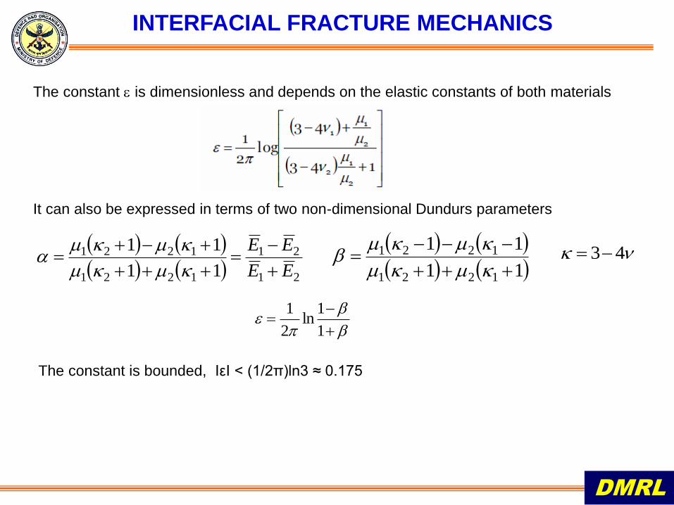
The constant is dimensionless and depends on the elastic constants of both materials
21
21
1221
1221
11
11
EE
EE
11
11
1221
1221
43
1
1ln
2
1
The constant is bounded, IεI < (1/2π)ln3 ≈ 0.175
It can also be expressed in terms of two non-dimensional Dundurs parameters

INTERFACIAL FRACTURE MECHANICS
DMRL
The amplitude of the stress intensity factor is defined by
This real-valued quantity has the familiar dimension
relates to the energy release rate G as
One complex number corresponds to two real numbers. For example, we can write a
complex number in terms of its amplitude and phase angle, namely
The phase angle specifies the mode of the load
INTERFACIAL FRACTURE MECHANICS
DMRL
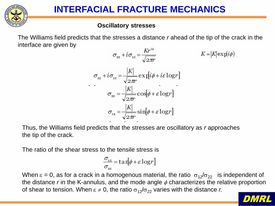
Oscillatory stresses
The Williams field predicts that the stresses a distance r ahead of the tip of the crack in the
interface are given by
Thus, the Williams field predicts that the stresses are oscillatory as r approaches
the tip of the crack.
The ratio of the shear stress to the tensile stress is
When = 0, as for a crack in a homogenous material, the ratio 12/22 is independent of
the distance r in the K-annulus, and the mode angle characterizes the relative proportion
of shear to tension. When 0, the ratio 12/22 varies with the distance r.
INTERFACIAL FRACTURE MECHANICS
DMRL
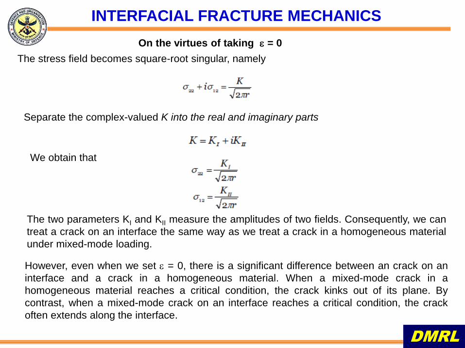
On the virtues of taking = 0
The stress field becomes square-root singular, namely
Separate the complex-valued K into the real and imaginary parts
We obtain that
The two parameters KI and KII measure the amplitudes of two fields. Consequently, we can
treat a crack on an interface the same way as we treat a crack in a homogeneous material
under mixed-mode loading.
However, even when we set = 0, there is a significant difference between an crack on an
interface and a crack in a homogeneous material. When a mixed-mode crack in a
homogeneous material reaches a critical condition, the crack kinks out of its plane. By
contrast, when a mixed-mode crack on an interface reaches a critical condition, the crack
often extends along the interface.
INTERFACIAL FRACTURE MECHANICS
DMRL
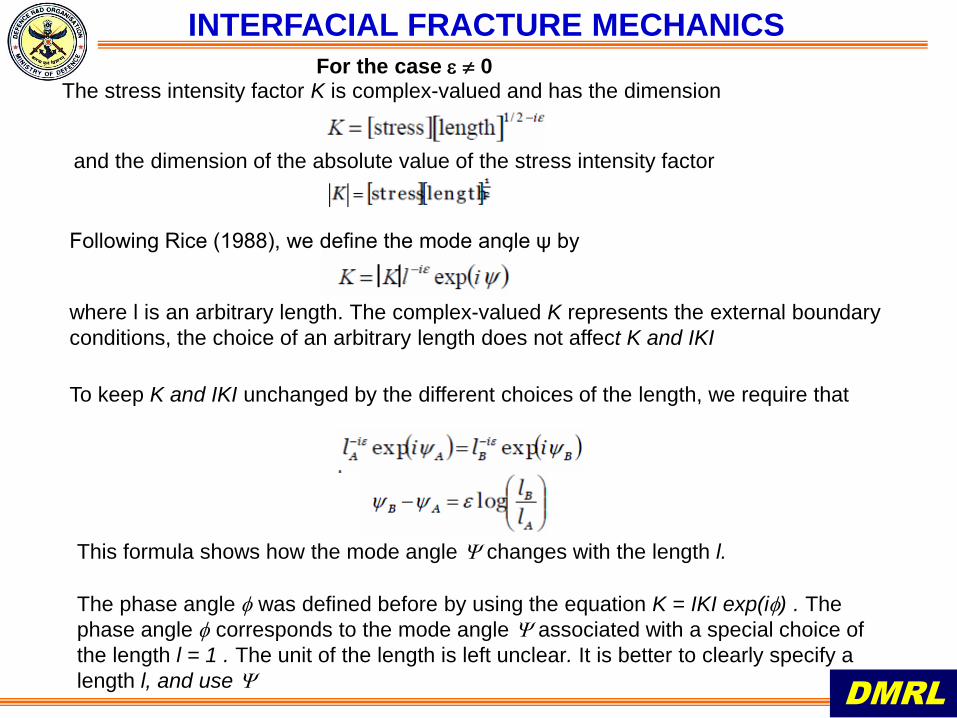
where l is an arbitrary length. The complex-valued K represents the external boundary
conditions, the choice of an arbitrary length does not affect K and IKI
Following Rice (1988), we define the mode angle ψ by
For the case 0 The stress intensity factor K is complex-valued and has the dimension
To keep K and IKI unchanged by the different choices of the length, we require that
This formula shows how the mode angle changes with the length l.
The phase angle was defined before by using the equation K = IKI exp(i) . The
phase angle corresponds to the mode angle associated with a special choice of
the length l = 1 . The unit of the length is left unclear. It is better to clearly specify a
length l, and use
and the dimension of the absolute value of the stress intensity factor
INTERFACIAL FRACTURE MECHANICS
DMRL
For the case 0
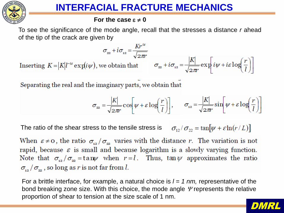
To see the significance of the mode angle, recall that the stresses a distance r ahead
of the tip of the crack are given by
The ratio of the shear stress to the tensile stress is
For a brittle interface, for example, a natural choice is l = 1 nm, representative of the
bond breaking zone size. With this choice, the mode angle represents the relative
proportion of shear to tension at the size scale of 1 nm.
INTERFACIAL FRACTURE MECHANICS
DMRL
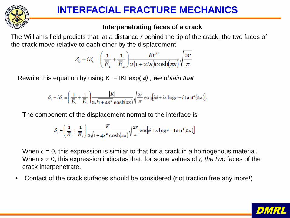
Interpenetrating faces of a crack
The Williams field predicts that, at a distance r behind the tip of the crack, the two faces of
the crack move relative to each other by the displacement
Rewrite this equation by using K = IKI exp(i) , we obtain that
The component of the displacement normal to the interface is
When = 0, this expression is similar to that for a crack in a homogenous material.
When 0, this expression indicates that, for some values of r, the two faces of the
crack interpenetrate.
• Contact of the crack surfaces should be considered (not traction free any more!)
INTERFACIAL FRACTURE MECHANICS
DMRL
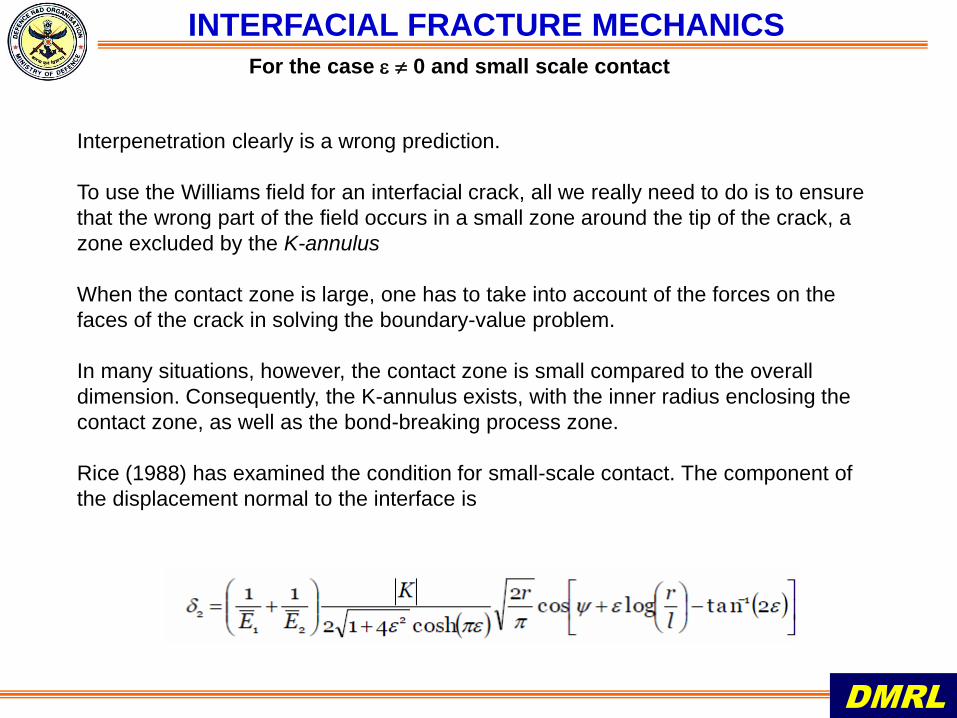
For the case 0 and small scale contact
Interpenetration clearly is a wrong prediction.
To use the Williams field for an interfacial crack, all we really need to do is to ensure
that the wrong part of the field occurs in a small zone around the tip of the crack, a
zone excluded by the K-annulus
When the contact zone is large, one has to take into account of the forces on the
faces of the crack in solving the boundary-value problem.
In many situations, however, the contact zone is small compared to the overall
dimension. Consequently, the K-annulus exists, with the inner radius enclosing the
contact zone, as well as the bond-breaking process zone.
Rice (1988) has examined the condition for small-scale contact. The component of
the displacement normal to the interface is
INTERFACIAL FRACTURE MECHANICS
DMRL
Assume that an annulus exists, whose inside radius is large compared to small-scale
events not modeled by the Williams field, and whose outside radius is small compared
to the length characteristic of the external boundary conditions.
Inside the annulus, the Williams field prevails, characterized by the complex-valued
stress intensity factor K.
For a given crack configuration, the stress intensity factor K is determined by solving the
elastic boundary value problem. Finite element method and other numerical methods
have been developed to determine the stress intensity factor.
The critical conditions for debonding can be formulated in terms of the complex-valued
stress intensity factors or strain energy release rates.
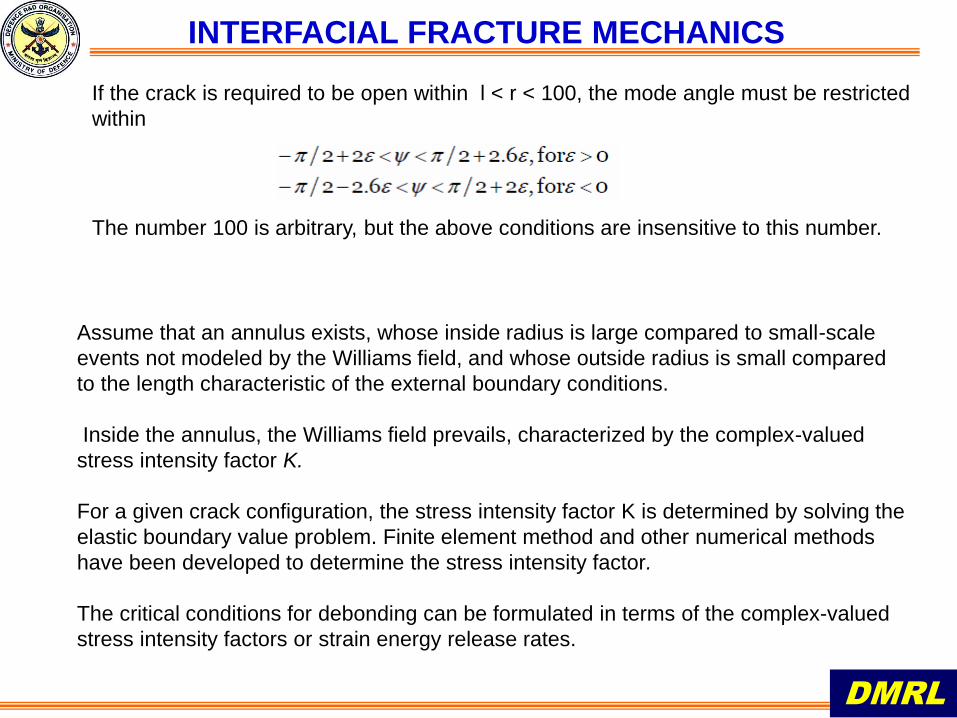
If the crack is required to be open within l < r < 100, the mode angle must be restricted
within
The number 100 is arbitrary, but the above conditions are insensitive to this number.
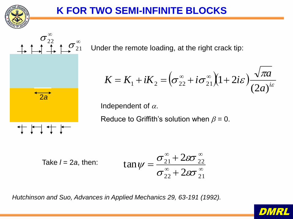
K FOR TWO SEMI-INFINITE BLOCKS
22
21 Under the remote loading, at the right crack tip:
2a
ia
aiiiKKK
)2(21212221
Independent of .
Reduce to Griffith’s solution when = 0.
Take l = 2a, then:
2122
2221
2
2tan
DMRL
Hutchinson and Suo, Advances in Applied Mechanics 29, 63-191 (1992).
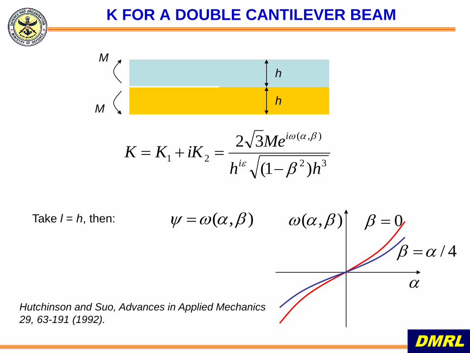
K FOR A DOUBLE CANTILEVER BEAM
M
M
h
h
32
),(
21
)1(
32
hh
MeiKKK
i
i
Take l = h, then: ),( ),(
0
4/
Hutchinson and Suo, Advances in Applied Mechanics
29, 63-191 (1992).
DMRL
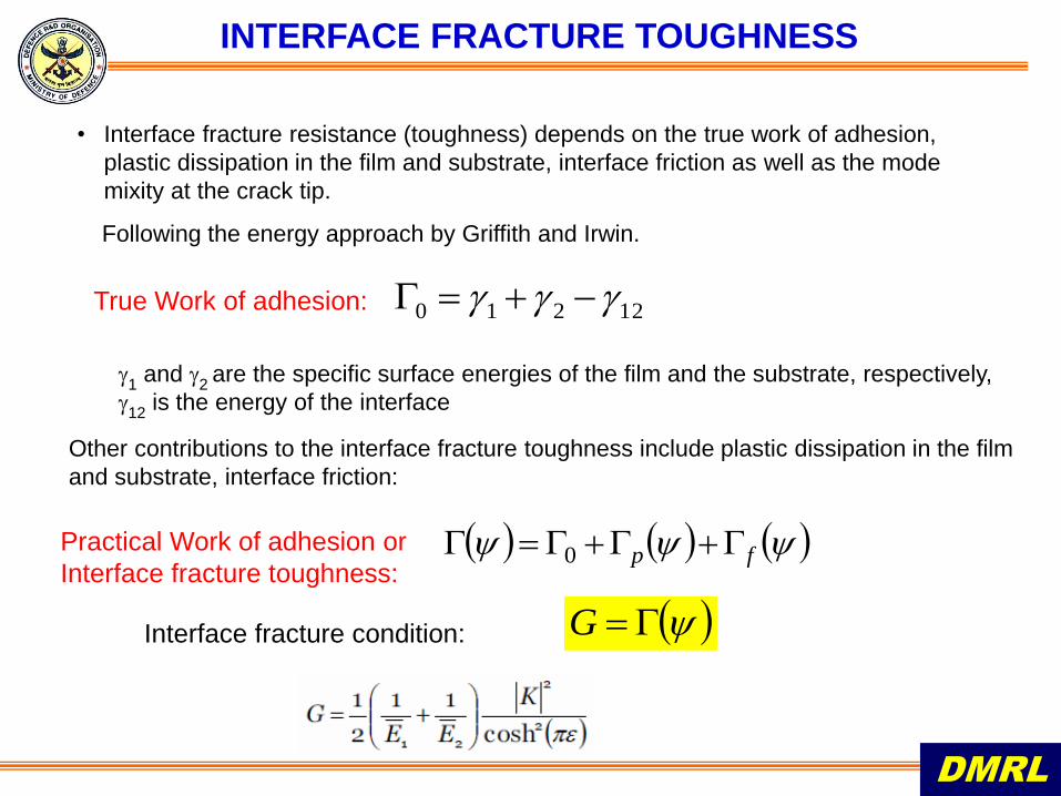
• Interface fracture resistance (toughness) depends on the true work of adhesion,
plastic dissipation in the film and substrate, interface friction as well as the mode
mixity at the crack tip.
DMRL
INTERFACE FRACTURE TOUGHNESS
Following the energy approach by Griffith and Irwin.
True Work of adhesion: 12210
1 and
2 are the specific surface energies of the film and the substrate, respectively,
12
is the energy of the interface
Other contributions to the interface fracture toughness include plastic dissipation in the film
and substrate, interface friction:
fp 0Practical Work of adhesion or
Interface fracture toughness:
Interface fracture condition: G
DMRL
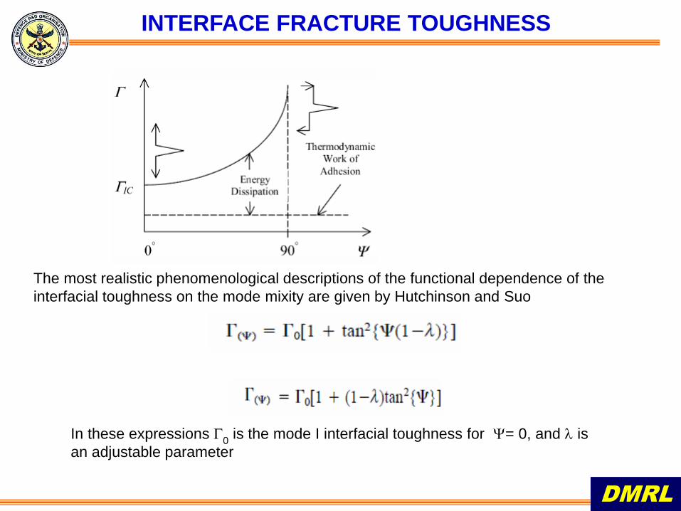
INTERFACE FRACTURE TOUGHNESS
The most realistic phenomenological descriptions of the functional dependence of the
interfacial toughness on the mode mixity are given by Hutchinson and Suo
In these expressions 0 is the mode I interfacial toughness for = 0, and is
an adjustable parameter
NANOINDENTATION
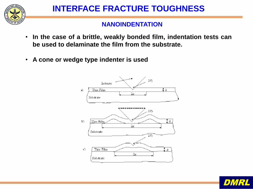
• In the case of a brittle, weakly bonded film, indentation tests can
be used to delaminate the film from the substrate.
• A cone or wedge type indenter is used
DMRL
INTERFACE FRACTURE TOUGHNESS
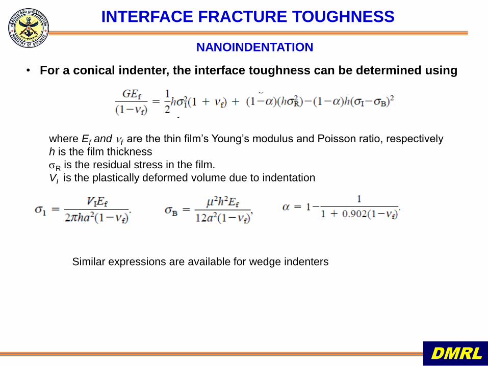
• For a conical indenter, the interface toughness can be determined using
DMRL
INTERFACE FRACTURE TOUGHNESS
NANOINDENTATION
where Ef and f are the thin film’s Young’s modulus and Poisson ratio, respectively
h is the film thickness
R is the residual stress in the film.
VI is the plastically deformed volume due to indentation
Similar expressions are available for wedge indenters
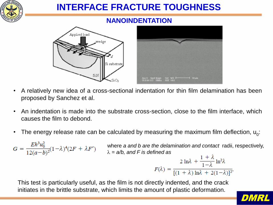
• A relatively new idea of a cross-sectional indentation for thin film delamination has been
proposed by Sanchez et al.
• An indentation is made into the substrate cross-section, close to the film interface, which
causes the film to debond.
• The energy release rate can be calculated by measuring the maximum film deflection, u0:
DMRL
INTERFACE FRACTURE TOUGHNESS
where a and b are the delamination and contact radii, respectively,
= a/b, and F is defined as
NANOINDENTATION
This test is particularly useful, as the film is not directly indented, and the crack
initiates in the brittle substrate, which limits the amount of plastic deformation.
DMRL
INTERFACE FRACTURE TOUGHNESS
PRECRACKED LINE SCRATCH TEST
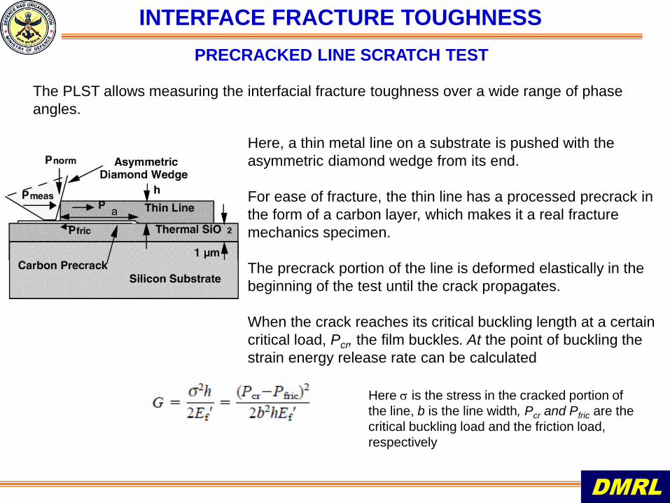
The PLST allows measuring the interfacial fracture toughness over a wide range of phase
angles.
Here, a thin metal line on a substrate is pushed with the
asymmetric diamond wedge from its end.
For ease of fracture, the thin line has a processed precrack in
the form of a carbon layer, which makes it a real fracture
mechanics specimen.
The precrack portion of the line is deformed elastically in the
beginning of the test until the crack propagates.
When the crack reaches its critical buckling length at a certain
critical load, Pcr, the film buckles. At the point of buckling the
strain energy release rate can be calculated
Here is the stress in the cracked portion of
the line, b is the line width, Pcr and Pfric are the
critical buckling load and the friction load,
respectively
• For thin films the only method which duplicates the mode mixity found
in actual films is based on residual stress induced debonding
• However, for most thin films the residual stress induced strain energy
release rate Gss is substantially lower than the interface debond energy
• Gss can be increased by depositing an additional material layer on the
film
• One has to ensure that for the additional layer
– deposition must be carried out at ambient temperature
– the layer must not react with the film
– the layer must have large residual tension upon deposition
DMRL
• Apart from Nanoindentation, other techniques have also been used for
Interface debond energy measurements
INTERFACE FRACTURE TOUGHNESS
INTERFACE FRACTURE TOUGHNESS
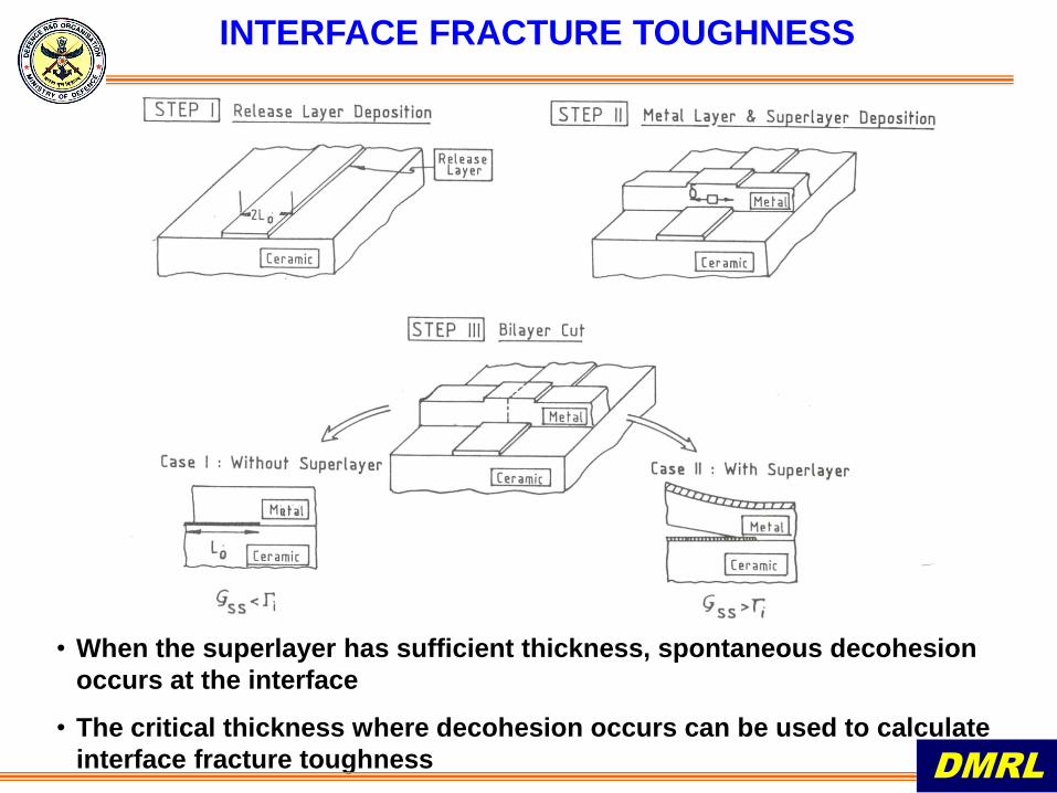
• When the superlayer has sufficient thickness, spontaneous decohesion
occurs at the interface
• The critical thickness where decohesion occurs can be used to calculate
interface fracture toughness DMRL
INTERFACE FRACTURE TOUGHNESS
DMRL
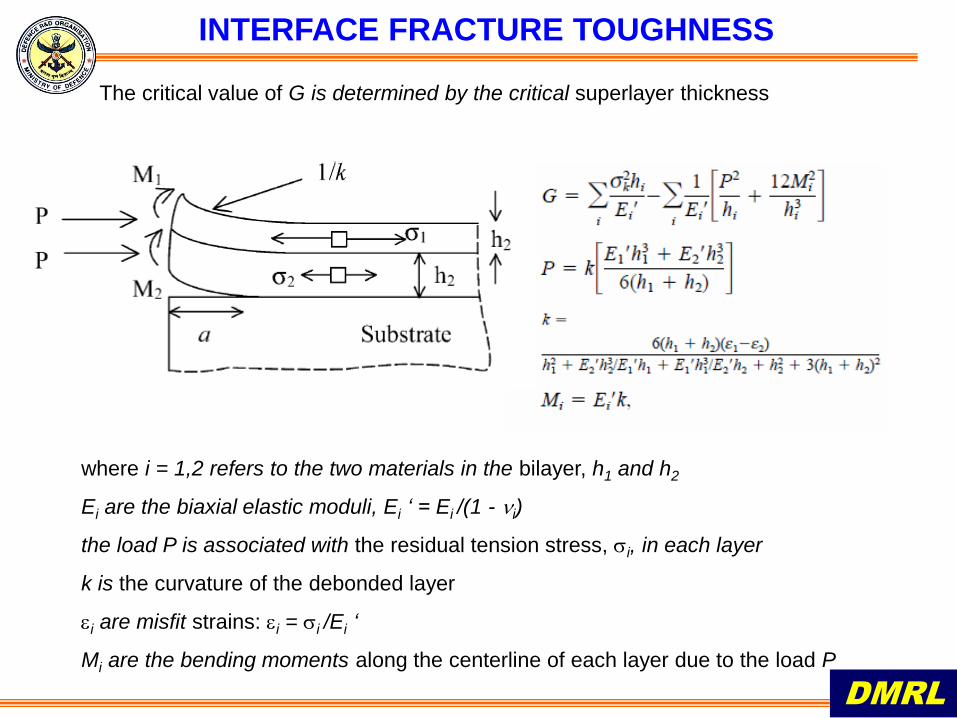
The critical value of G is determined by the critical superlayer thickness
where i = 1,2 refers to the two materials in the bilayer, h1 and h2
Ei are the biaxial elastic moduli, Ei ‘ = Ei /(1 - i)
the load P is associated with the residual tension stress, i, in each layer
k is the curvature of the debonded layer
i are misfit strains: i = i /Ei ‘
Mi are the bending moments along the centerline of each layer due to the load P
INTERFACE FRACTURE TOUGHNESS
DMRL
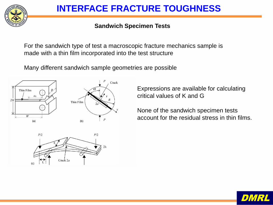
Sandwich Specimen Tests
For the sandwich type of test a macroscopic fracture mechanics sample is
made with a thin film incorporated into the test structure
Many different sandwich sample geometries are possible
Expressions are available for calculating
critical values of K and G
None of the sandwich specimen tests
account for the residual stress in thin films.
DMRL
THANK YOU
BIBLIOGRAPHY
DMRL
1) T. L. Anderson, Fracture Mechanics : Fundamentals and Applications, CRC Press, New York 2005
2) A.A. Volinsky, N.R. Moody, W.W. Gerberich, Acta Materialia 50 (2002) 441–466
3) Z. Suo, http://imechanica.org/node/7448
4) Z. Suo, http://www.elsevier.com/locate/cosi
5) Z Suo, Encyclopedia of Materials: Science and Technology, Second Edition, Elsevier Science in
2001
6) J.M. Sanchez, S. El-Mansy, B. Sun T. Scherban, N. Fang, D. Pantuso, W. Ford, M.R. Elizalde,
J.M. Martinez-Escanola, A. Martin-Meizoso, J. Gil-Sevillano, M. Fuentes, J. Maiz, Acta Mater
1999; 4405.
7) M.D. Kriese, W.W. Gerberich, J Mater Res 1999;14:3007.