Embed Size (px)
Citation preview
13th LACCEI Annual International Conference: “Engineering Education Facing the Grand Challenges, What Are We Doing?” July 29-31, 2015, Santo Domingo, Dominican Republic ISBN: 13 978-0-9822896-8-6 ISSN: 2414-6668 DOI: http://dx.doi.org/10.18687/LACCEI2015.1.1.176
Interface Design for OSP / Satellite Device
Hernan Paz Penagos, Ph.D.1, Johnny Alexander Lopez Arevalo, Eng.1, Marco Andrés Ortiz Niño, Eng.1
1 Colombian School of Engineering Julio Garavito, Colombia, [email protected], [email protected], [email protected].
Abstract– This paper presents the design and construction of communication interfaces EUSART (Enhanced Universal Synchronous Asynchronous Receiver Transmitter) using the OSP / Satellite device. The technological product that integrates hardware, software and communications interfaces, was the result of a research project developed by the Colombian School of Engineering JULIO GARAVITO jointly with the company OSP LTDA and funded by COLCIENCIAS. This OSP / Satellite device reused equipment GPRS or also called units Automatic Vehicle Location: AVL, specifically TT8750 + of Skypatrol and SYRUS of DCT, which are used for locating and tracking mobile assets with cellular coverage, and they add a channel satellite backup via modem STX-2 Globalstar®, to ensure continuity in communication at any geographic area in Colombia.
Keywords— satellite device, OSP, tracking, communications, EUSART.
Digital Object Identifier (DOI): http://dx.doi.org/10.18687/LACCEI2015.1.1.176 ISBN: 13 978-0-9822896-8-6 ISSN: 2414-6668
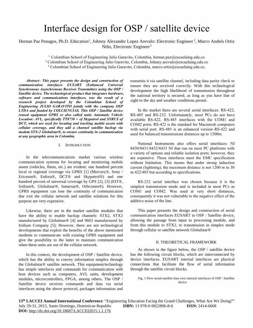
Interface design for OSP / satellite device Hernan Paz Penagos, Ph.D. Education1, Johnny Alexander Lopez Arevalo: Electronic Engineer 2, Marco Andrés Ortiz
Niño, Electronic Engineer3
1 Colombian School of Engineering Julio Garavito, Colombia, [email protected] 2 Colombian School of Engineering Julio Garavito, Colombia, [email protected]
3 Colombian School of Engineering Julio Garavito, Colombia, [email protected].
Abstract– This paper presents the design and construction of
communication interfaces EUSART (Enhanced Universal
Synchronous Asynchronous Receiver Transmitter) using the OSP /
Satellite device. The technological product that integrates hardware,
software and communications interfaces, was the result of a
research project developed by the Colombian School of
Engineering JULIO GARAVITO jointly with the company OSP
LTDA and funded by COLCIENCIAS. This OSP / Satellite device
reused equipment GPRS or also called units Automatic Vehicle
Location: AVL, specifically TT8750 + of Skypatrol and SYRUS of
DCT, which are used for locating and tracking mobile assets with
cellular coverage, and they add a channel satellite backup via
modem STX-2 Globalstar®, to ensure continuity in communication
at any geographic area in Colombia.
I. INTRODUCTION
In the telecommunications market various wireless
communication systems for locating and monitoring mobile
assets (vehicles, fleets, etc.) are evident: one hundred percent
local or regional coverage via GPRS [1] (Mercury®, Sony /
Ericsson®, Enfora®, DCT® and Skypatrol®) and one
hundred percent of universal coverage by GPS [2], [3] (EIT®,
Iridium®, Globalstar®, Inmarsat®, Orbcomm®). However,
GPRS equipment can lose the continuity of communication
due exit the cellular network and satellite solutions for this
purpose are very expensive.
Likewise, there are in the market satellite modules that
have the ability to enable backup channels: STX2, STX3
manufactured by Globalstar® [4] and 9603 manufactured by
Iridium Company [5]; However, there are not technological
developments that exploit the benefits of the above mentioned
modems to communicate with existing GPRS equipment and
give the possibility to the latter to maintain communication
when these units are out of the cellular network.
In this context, the development of OSP / Satellite device,
which has the ability to convey information simplex through
the Globalstar® satellite network. This equipment/technology
has simple interfaces and commands for communication with
host devices such as computers, AVL units, development
modules, microcontrollers, FPGA, among others. The OSP /
Satellite device receives commands and data via serial
interfaces using the above protocol, packages information and
transmits it via satellite channel, including data parity check to
ensure they are received correctly. With this technological
development the high likelihood of transmission throughout
the national territory is secured, as long as you have line of
sight to the sky and weather conditions permit.
In the market there are several serial interfaces: RS-422,
RS-485 and RS-232. Unfortunately, most PCs do not have
available RS-422, RS-485 interfaces with the COM1 and
COM2 ports. RS-422 is the standard for Macintosh computers
with serial port. RS-485 is an enhanced version RS-422 and
used for balanced transmissions distances up to 1200m.
National Instruments also offers serial interfaces: NI
8430/8431/8432/8433 NI that run on most PC platforms with
a variety of options and reliable isolation ports; however, they
are expensive. These interfaces meet the EMC specification
without limitation. This means that under strong induction
current (lightning), the maximum distance is not 1200 m to 30
m 422/485 but according to specifications.
RS-232 serial interface was chosen because it is the
simplest transmission mode and is included in most PCs as
COM1 and COM2. Was used at very short distances,
consequently it was not vulnerable to the negative effect of the
additive noise of the line.
This paper presents the design and construction of serial
communication interfaces EUSART to OSP / Satellite device,
allowing the passage from input to processing module, and
from this module to STX2, to transmission in simplex mode
through cellular or satellite network Globalstar®
II. THEORETICAL FRAMEWORK
As shown in the figure below, the OSP / satellite device
has the following circuit blocks, which are interconnected by
device interfaces. EUSART internal interfaces are physical
connections that facilitate the flow of serial information
through the satellite circuit blocks.
Fig. 1 Flow serial-satellite data over internal interfaces of OSP / Satellite
device
13th LACCEI Annual International Conference: “Engineering Education Facing the Grand Challenges, What Are We Doing?” July 29-31, 2015, Santo Domingo, Dominican Republic ISBN: 13 978-0-9822896-8-6 ISSN: 2414-6668 DOI: http://dx.doi.org/10.18687/LACCEI2015.1.1.176

13th LACCEI Annual International Conference: “Engineering Education Facing the Grand Challenges, What Are We Doing?”
July 29-31, 2015, Santo Domingo, Dominican Republic
The data from the external electronic device are variable
measurement and / or geolocation as latitude, longitude,
direction, altitude, speed, temperature, humidity and virtually
any measurable variable. These must be in ASCII (American
Standard Code for Information Interchange) format and cannot
exceed 300 bytes to avoid buffer overflows in the
microcontroller.
The information from the external electronic device is sent
to the MAX232 via serial link and in this to the EUSART 2
serial interface of the microcontroller PIC18LF26K22 [6] so
that they are processed. Then the micro re-transmitted through
the serial interface EUSART 1 to satellite modem STX2 from
the manufacturer Globalstar® who is in charge of satellite
transmission [7], [8].
The OSP / Satellite device has three modes of operation:
two basic and one advanced. Both basic operation modes have
the same purpose: the satellite data transmission received from
external equipment when they do not have cellular coverage or
other means of wireless transmission. To enable any of the
three modes of operation will be three processing routines in
the micro-controller. It uses EUSART communication
interfaces that are compatible with existing devices and the
satellite modem.
The basic operating modes allow the reception of serial
data from the following external equipment AVL: SYRUS®,
Skypatrol: TT8750® and Enfora: GSM1308®. Advanced
operation mode allows communication with units, regardless
of its purpose reference; and through an RS232 serial
interface, data transmitted in accordance with the ASCII [9]
standard.
III. METHODOLOGY AND DESIGN
Modeling microcontroller and communication interfaces.
For the microcontroller to fulfill its role of processing data
in the OSP / Satellite device firmware is necessary to configure
using the modules shown in the following figure:
Fig. 2 Microcontroller modules
The storage module has a nonvolatile memory EEPROM
(Electrically Erasable Programmable Read-only) for storing
data bytes up to 1024 in three forms (two fixed and one
variable) that represent each mode of the OSP / Satellite
device.
The data stored in memory are:
Fixed data stored one (for mode one):
• 0x5B 0x7E 0x02 0x5D (in Hexadecimal)
• [~ . ] (ASCII)
Fixed data stored two (for mode two):
• 0x5B 0x7E 0x02 0x5D (in Hexadecimal)
• [~ . ] (ASCII)
Programmable data stored (for mode three):
Fig. 3 Data storage
Hexadecimal Storage Range: x000 x3FF.
The communication module two or EUSART 2 allows
reception and transmission of serial data and is configured
with the following parameters:
Rango de almacenamiento en Hexadecimal: x000 x3FF.
TABLE I
FEATURES OF EUSART 2 INTERFACE
Variable 1 Number of bits 1
Variable 2 Number of bits 2
Variable n* Number of bits n**
This module is responsible for receiving data in the
receive buffer and then deliver it to the processing module or
storage module according to the information contained in it.
Fig. 4 Diagram of decision according to data received
In order to make the data in the buffer pass to processing
module it must satisfy the ASCII standard and not exceed the
maximum buffer size (300 bytes). When the OSP / Satellite
device is in basic operation mode, the frame to be received in
the buffer corresponds to TAIP protocol (Trimble ASCII
Interface protocol) and its structure is shown below [10]:
Fig. 5 TAIP frame. Interface A.
TABLE II
DESCRIPTION OF TAIP FRAME. INTERFACE A.
Extended
values
[EV-TAGS] Extended values when more information is
required to know
< End frame delimiter
> Start frame delimiter (ASCII 62 o 0x3E)
R Frame qualifier
EV Two-character identifier
#EV Event number: 0 a 99
Weeks Number of weeks from 0:00 AM january 6, 1980
D Day 0 being Sunday
Hour Time report generated in seconds from 0:00 to the current
date
Latitude EEEFFFFF. Latitude WGS-84. EEE represents the value in
degrees and FFFFF decimals
Longitude GGGGHHHHH. Length WGS-84. GGGG represents the
value in degrees and decimal part HHHHH.
Speed Speed in mph

13th LACCEI Annual International Conference: “Engineering Education Facing the Grand Challenges, What Are We Doing?”
July 29-31, 2015, Santo Domingo, Dominican Republic
Heading Heading in degrees
Extended
values
[EV-TAGS] Extended values when more information is
required to know
< End of frame delimiter
For the advanced mode, the frame to be received is valid
for protocols that use the ASCII standard and do not exceed
the buffer size (300 bytes).
The processing module converts the ASCII data received
by the communication module 2 in decimal values without
affecting its integrity, grouped to form one or more messages,
each of 72 bits that are transmitted by the communication
module one.
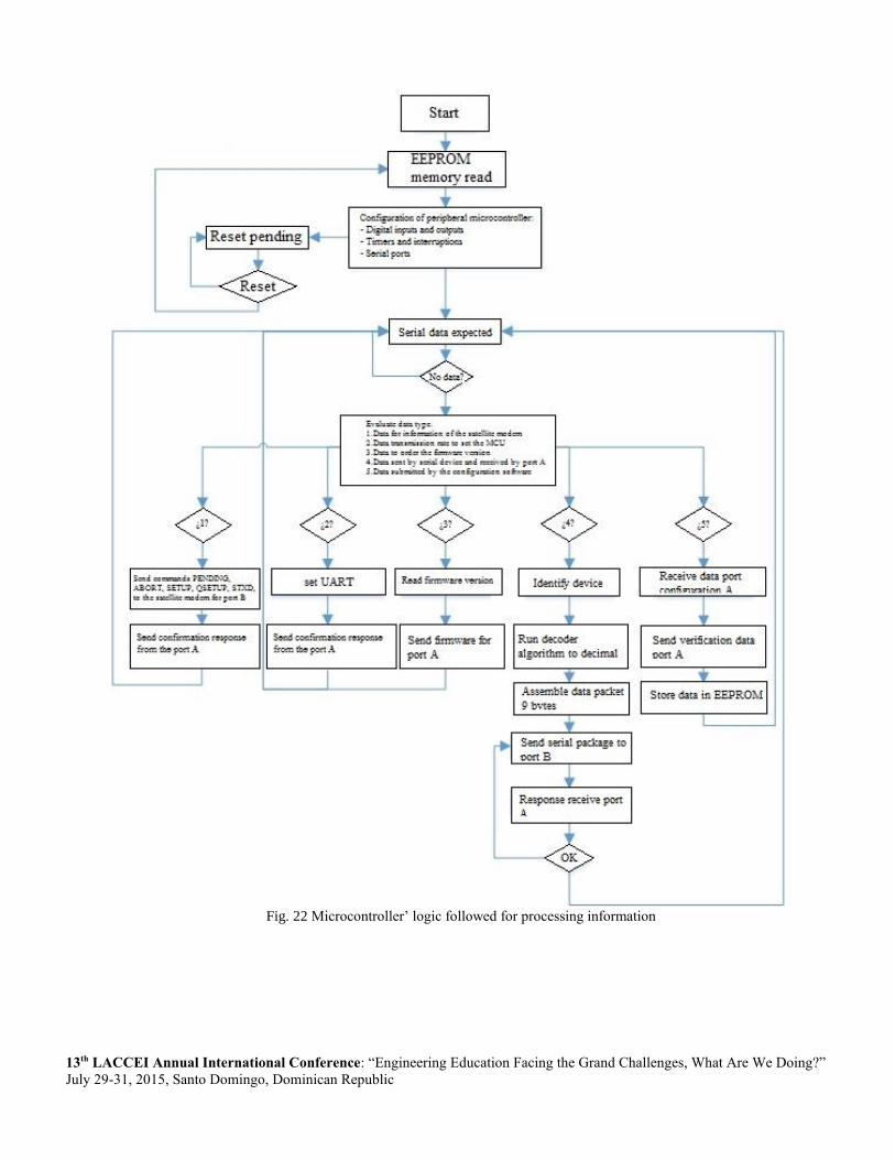
The processing is performed according to the operating
mode previously stored in the EEPROM memory and is
performed by the microcontroller following the logic shown in
the following figure:
Fig. 6 Microcontroller’ logic followed for processing information
The communication module one or EUSART 1 enables
the transmission and reception of serial data and is configured
with the following parameters: TABLE III
CONFIGURATION OF EUSART 1 INTERFACE.
Type Serial UART
Bit rate 9600 bps
Type of channel Full duplex
Asynchronous
Parity Not
Stop bits 1 bit
Bits of data 8 bits
This module sends a data packet that already has passed
through the processing module and which as noted above has a
size of nine bytes. Interpreting the information contained in the
packet is done according to the data held in the storage
module, as well: for fixed data stored in one mode, the
transmitted frame is:
Fig. 7 Satellite frame 1. Interface B
* Result of orientation should be multiplied by 10 to get the original
value. The margin of error for this result is 5 degrees.
** Speed in mph.
For fixed data stored mode two, the transmitted frame is:
Fig. 8 Satellite frame 2. Interface B
* Result of orientation should be multiplied by twelve to get the
original value. The margin of error for this result is six degrees.
** Speed in m / s
*** The time format will be presented one to twelve bits, for the case of
the previous figure ten bits are used, of which the four least significant bits
are used for time and for the remaining six minutes.
For variable data, the frame is subject to the values
programmed in the storage module as well:
TABLE IV
PRELIMINARY DESCRIPTION PLOT TO OPTION THREE MENU.
Variable 1 Number of bits 1
Variable 2 Number of bits 2
Variable n* Number of bits n**
* Up to 72 for a nine bytes message
** The amount of bits for each variable is subject to validation to meet
all nine variables occupy bytes sent by message.
Modem STX2
The STX2 modem has a patch antenna type [11], [12] a
digital input (which enables or disables) and a bidirectional
serial interface. This interface has supported configuration
parameters with the communication protocol established in the
EUSART 1 interface (TABLE III). See Figure 1.
In the following two figures the state of the serial interface
STX2 shown when available / unavailable to receive data from
the micro controller.
Fig. 9 Communication DTE / STX-2, when the module is ready to
receive data.
Source: Gen 2 satellite transmitter product data sheet. Page 12.
Fig. 10 Communication DTE / STX-2, when the module is not ready to
receive data.
Source: Gen 2 satellite transmitter product data sheet. Page 12.
Communication with the modem is based on transmit a
command and wait for a response [13]. The commands used in
the transmission having a size of one byte, and are part of the
transmitted data packet. When a packet is received in the
STX2, a packet with 0X00 commands, internal message 9
bytes is removed and relocated to a new package that is re-
transmitted to the satellite using an RF carrier (see Figure 11).
Fig. 11 RF carrier which modulates the message to F = 1.6 GHz
If the user message is more than nine bytes, is divided into
several packages. The frame structure begins with a preamble,
continues with the unit identifier, the number of messages to
be transmitted, the number of packets per message nine bytes
of user information (9 bytes) and ends with a 24-bit CRC [14].
Fig. 12 Data frame of the air interface.
Source: Gen 2 satellite transmitter product data sheet. Page 7.

13th LACCEI Annual International Conference: “Engineering Education Facing the Grand Challenges, What Are We Doing?”
July 29-31, 2015, Santo Domingo, Dominican Republic
Once the packet is created, it is sent repeatedly. The
number of transmission attempts and the time interval for these
attempts are configurable parameters [15]. The time interval is
randomly selected as the minimum and maximum range set.
To send multiple packets over air interface should follow a
sequence for all attempts. For example, for transmission of
three packets the sequence shown in the figure below is
followed.
Fig. 13 Sequence followed by three packets that are sent over the air
interface.
Source: Gen 2 satellite transmitter product data sheet. Page 8.
IV. RESULTS
Shown below the configuration of the communication
interfaces, data are transmitted, received and stored in the
internal memory of the device. The data received in the
microcontroller PIC18(L)F2X/4XK22 [6] are stored in a
buffer of size 300 bytes, and shows that according to the
operating mode extracting relevant data and subsequent
processing to assemble packets of nine bytes that are
transmitted to the satellite module.
The following figure shows the records that show the
configuration set of serial interfaces using a debug done on the
microcontroller. There are shown in bits transmission rates,
parity bits, message length, and stop bits.
Fig. 14 SFR registers and interrupt reception.
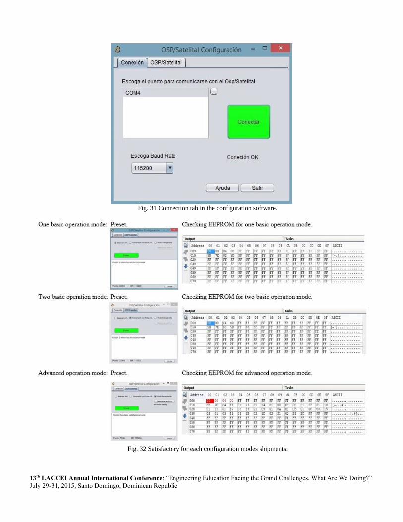
The following figure shows the connection with the OSP /
Satellite device.
Fig. 15 Connection tab in the configuration software.
The following figure shows the OSP / Satellite device
recognizes three modes in which you can configure; likewise,
each of the three operating modes is displayed in the
EEPROM.
Fig. 16 Satisfactory for each configuration modes shipments.
In the following figure, shows received frames for the two
basic operating modes; this happens when the OSP / Satellite
device is in operation.
Fig. 17 Frames transmitted and received in USART and land for two
basic operation mode.
V. CONCLUSIONS
No flow control data to the serial interface is used due to
two factors: The size of the buffer (300 bytes) and 64MHz
frequency used by the microcontroller [16]. Therefore, the
expected frame from the external device receiving the
microcontroller cannot exceed 300 bytes.
The data stored in the buffer are in ASCII format, so it is
necessary to know the narrative that delivers the external
equipment to prevent buffer overflows leading to loss data
communication.
The data processing is subject primarily buffer size in
bytes that enables satellite transmission module, for this is
necessary data conversion to decimal ASCII.
REFERENCES
[1] R. J. Bates, “GPRS”. Kindle edición, Mc Graw-Hill. New York, 350p.
[2] Z. Zhao, W. Zhou, and N. Wang, N. “Shipping Monitoring System Based
on GPS and GPRS Technology”, in 2009 WASE International
Conference on Information Engineering ICIE, vol. 1, Washington, DC,
USA, 2009, pp.346-349.
[3] Orbcomm system review. (2001, Aug.). [Online]. Available:
http://www.m2mconnectivity.com.au/sites/default/files/more-
information/System_Overview_Rev_G.pdf
[4] Axxon - Globalstar. (2005, May). Satellite Transmitter Product Data
Sheet. [Online]. Available:
http://common.globalstar.com/doc/axonn/stx2-datsasheet.pdf
[5] Iridium Communications - Revised 4.0. Iridium 9602 SBD Transceiver
Developer's Guide (2014 Jan.). [Online]. Available: http://www.g-
layer.com.au/wp-
content/uploads/IRDM_9602DeveloperGuideV4_DEVGUIDE_Sep2012.
[6] Microchip Technology Incorporated (2012, June). PIC18 (L) F2X /
4XK22 Data Sheet 28/40/44-Pin, Low-Power and High-Performance
Microcontrollers with XLP Technology. [Online]. Available:
www.tme.eu/es/Document/.../pic18lf2x_4xk22.pdf
[7] A. Goldsmith. “Wireless communications”. Fourth edition, Cambridge
university press. Stanford University. Santa Barbara, California. 2005.
386p.
[8] S. E. Alberto. “Fundamentals of mobile communication systems”. First
edition, McGraw-Hill / Inter of Spain, SAU, 2004, 674p.
[9] M. Wael, A. A. El-Medany, R. Al-Hakim, S. Al-Irhayim and M. Nousif.
"Implementation of GPRS-Based Positioning System Using PIC
Microcontroller" 2nd International Conference on Computational
Intelligence, Communication Systems and Networks CICSYN, 2010, pp.
365-368.
[10] W. On-Medany, A. Al-Omary, R. Al-Hakim, S. Al-Irhayim and M.
Nusaif, M. “A Cost Effective Real-Time Tracking System Prototype
Using Integrated GPS / GPRS Module”, sixth International Conference
on Wireless and Mobile Communications: ICWMC, 2010, pp.521-525.
[11] C.A. Balanis. “Antenna theory: analysis and design”, fourth edition,
John Wiley & Sons, Inc. New Jersey, 2005. 1047 pp.
[12] H. Paz. “Digital communications systems”, first edition, Editorial:
Colombian School of Engineering. Bogotá-Colombia. 2009. 399 p.
[13] B. Jun, W. Lu and L. Yue. “Traffic Data Collection System for Floating
Car Based on GPS / GPRS / MM”, second WRI Global Congress on
Intelligent Systems: GCIS, vol. 3, 2010, pp.66-69.
[14] M. J. Donahoo and K. L. Calvert. “TCP / IP Sockets”, in C. Morgan
Kaufman Publishers. USA. 2001
[15] M. Scarpino. “Designing Circuit Boards with Eagle”, Kindle edition,
Prentice Hall, United Kingdom. 2014. 298p.
[16] S. Haykin. “Communications systems”. Fourth edition. John Wiley &
Sons, Inc. USA. 984p.

13th LACCEI Annual International Conference: “Engineering Education Facing the Grand Challenges, What Are We Doing?”
July 29-31, 2015, Santo Domingo, Dominican Republic
LIST OF FIGURES
Fig. 17 Flow serial-satellite data over internal interfaces of OSP / Satellite device
Fig. 18 Microcontroller modules

13th LACCEI Annual International Conference: “Engineering Education Facing the Grand Challenges, What Are We Doing?”
July 29-31, 2015, Santo Domingo, Dominican Republic
Fig. 19 Data storage
Fig. 20 Diagram of decision according to data received
Fig. 21 TAIP frame. Interface A.
13th LACCEI Annual International Conference: “Engineering Education Facing the Grand Challenges, What Are We Doing?”
July 29-31, 2015, Santo Domingo, Dominican Republic
Fig. 22 Microcontroller’ logic followed for processing information

13th LACCEI Annual International Conference: “Engineering Education Facing the Grand Challenges, What Are We Doing?”
July 29-31, 2015, Santo Domingo, Dominican Republic
Fig. 23 Satellite frame 1. Interface B
Fig. 24 Satellite frame 2. Interface B
Fig. 25 Communication DTE / STX-2, when the module is ready to receive data.

13th LACCEI Annual International Conference: “Engineering Education Facing the Grand Challenges, What Are We Doing?”
July 29-31, 2015, Santo Domingo, Dominican Republic
Fig. 26 Communication DTE / STX-2, when the module is not ready to receive data
Fig. 27 RF carrier which modulates the message to F = 1.6 GHz

13th LACCEI Annual International Conference: “Engineering Education Facing the Grand Challenges, What Are We Doing?”
July 29-31, 2015, Santo Domingo, Dominican Republic
Fig. 28 Data frame of the air interface.
Fig. 29 Sequence followed by three packets that are sent over the air interface.
Fig. 30 SFR registers and interrupt reception.
13th LACCEI Annual International Conference: “Engineering Education Facing the Grand Challenges, What Are We Doing?”
July 29-31, 2015, Santo Domingo, Dominican Republic
Fig. 31 Connection tab in the configuration software.
Fig. 32 Satisfactory for each configuration modes shipments.

13th LACCEI Annual International Conference: “Engineering Education Facing the Grand Challenges, What Are We Doing?”
July 29-31, 2015, Santo Domingo, Dominican Republic
Fig. 17 Frames transmitted and received in USART and land for two basic operation mode