Embed Size (px)
Citation preview

www.sensirion.com Version 0.94 – D1 – June 2019 1/20
Interface Description Sensirion SCD30 Sensor Module
CO2, humidity, and temperature sensor
▪ NDIR CO2 sensor technology ▪ Integrated temperature and humidity sensor ▪ Best performance-to-price ratio ▪ Dual-channel detection for superior stability ▪ Small form factor: 35 mm x 23 mm x 7 mm ▪ Accuracy CO2 sensor: ± (30 ppm + 3%) ▪ Fully calibrated with digital interface UART or I2C
Contents
1 Digital interface description
1.1 I2C Protocol 1.2 Modbus protocol 1.3 PWM protocol 1.4 Sensor commands 1.5 Signal conversion to physical values
2 Important Notices
2.1 Warning, Personal Injury 2.2 ESD Precautions 2.3 Warranty
3 Headquarters and Subsidiaries
www.sensirion.com Version 0.94 – D1 – June 2019 2/20
1 Digital interface description The SCD30 digital interface is compatible with the I2C protocol and the Modbus protocol. For selecting Modbus protocol, the SEL pin needs to be pulled to VDD Voltage during power-up of the SCD30 sensor module. It is not possible to switch the communication protocol during operation. Please refer to datasheet.
1.1 I2C Protocol
Maximal I2C speed is 100 kHz and the master has to support clock stretching. Clock stretching period in write- and read-frames is 12 ms, however, due to internal calibration processes a maximal clock stretching of 150 ms may occur once per day. For detailed information to the I2C protocol, refer to NXP I2C-bus specification1. SCD30 does not support repeated start condition. Clock stretching is necessary to start the microcontroller and might occur before every ACK. I2C master clock stretching needs to be implemented according to the NXP specification. The boot-up time is < 2 s.
1.1.1 I2C Address
After power-up of the sensor, the I2C address of the module is set to the address 0x61.
1.1.2 I2C Sequence
The commands issued by the I2C master are 16 bit with an optional parameter. Data sent to the master is protected by a CRC. This also applies to data arguments sent to the sensor, please see chapter 1.1.3 for CRC checksum calculation. 2 byte data sent from or received by the sensor is always succeeded with an 8 bit CRC. Examples are shown below.
I2C write 16bit command without arguments
Example: Stop measurements 0x0104
START 0xC2 0x01 0x04 STOP (Red: Write Header; Blue: Read Header; Black: Data; Green: CRC; Start Condition: START; Stop Condition: STOP)
1 http://www.nxp.com/documents/user_manual/UM10204.pdf
S W I2CAddress Cmd MSB AC
K
Cmd LSB AC
K
Clock
Stretching P
AC
K
www.sensirion.com Version 0.94 – D1 – June 2019 3/20
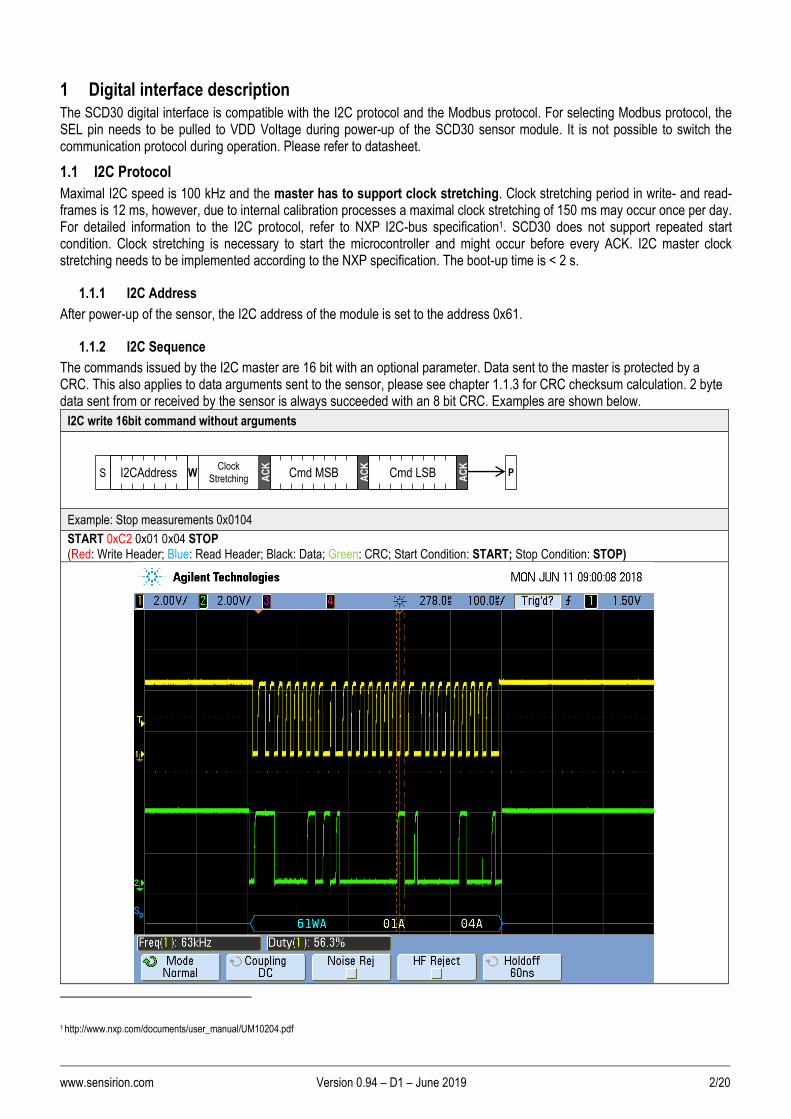
I2C write 16bit command with arguments
Example: Trigger continuous measurement (Pressure = 0mBar) START 0xC2 0x00 0x10 0x00 0x00 0x81 STOP (Red: Write Header; Blue: Read Header; Black: Data; Green: CRC; Start Condition: START; Stop Condition: STOP)
S W I2CAddress Cmd MSB AC
K
Cmd LSB AC
K
Clock Stretching A
CK
Data0 MSB AC
K
Data0 LSB AC
K
CRC0 P
or Data1 MSB A
CK
Data1 LSB AC
K
CRC1 P
or DataN MSB A
CK
DataN LSB AC
K
CRCN P
AC
K
AC
K
AC
K
www.sensirion.com Version 0.94 – D1 – June 2019 4/20
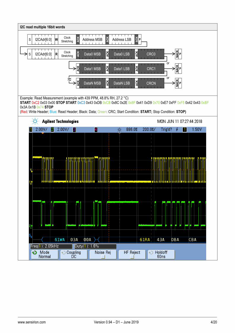
I2C read multiple 16bit words
Example: Read Measurement (example with 439 PPM, 48.8% RH, 27.2 °C) START 0xC2 0x03 0x00 STOP START 0xC3 0x43 0xDB 0xCB 0x8C 0x2E 0x8F 0x41 0xD9 0x70 0xE7 0xFF 0xF5 0x42 0x43 0xBF 0x3A 0x1B 0x74 STOP (Red: Write Header; Blue: Read Header; Black: Data; Green: CRC; Start Condition: START; Stop Condition: STOP)
S R I2CAdr[6:0] Data0 MSB AC
K
Data0 LSB
NA
CK
Clock Stretching P
AC
K
Data1 MSB AC
K
Data1 LSB
AC
K
DataN MSB AC
K
DataN LSB
or
AC
K
or
NA
CK
P
NA
CK
P
≈
AC
K
CRC0
AC
K
CRC1
AC
K
CRCN
S W I2CAdr[6:0] Address MSB AC
K
Address LSB AC
K
Clock Stretching P
AC
K
≈

www.sensirion.com Version 0.94 – D1 – June 2019 5/20
Table 1 I2C write and read communication frames. SDA is controlled by the I2C master in clear blocks and by the sensor in dark blocks.
1.1.3 I2C Checksum calculation
The checksum byte for I2C communication is generated by a CRC algorithm with the following properties:
Preceding Command Value
Name CRC-8
Protected Data read data
Width 8 bits
Polynomial 0x31 (x8 + x5 + x4 + 1)
Initialization 0xFF
Reflect Input false
Reflect Output false
Final XOR 0x00
Example CRC(0xBEEF) = 0x92

www.sensirion.com Version 0.94 – D1 – June 2019 6/20
1.2 Modbus protocol
For selecting Modbus protocol, the SEL pin needs to be pulled to VDD Voltage. Please refer to datasheet.
The supported baud rate is 19200 Baud with 8 Data bits, 1 Start bit and 1 Stop bit, no Parity bit.
More details on the Modbus protocol can be found here:
Description Link
General introduction http://www.modbus.org/docs/Modbus_over_serial_line_V1_02.pdf
Modbus frame generator http://modbus.rapidscada.net/
Modbus CRC generator https://www.lammertbies.nl/comm/info/crc-calculation.html
1.2.1 Modbus address
Modbus address is 0x61.
1.2.2 Modbus function codes
Available function codes are
Function code Description
3 Read holding registers
4 Read input registers
6 Write single holding register
1.3 PWM output
The SCD30 features the possibility to read out the CO2 concentration via the PWM protocol. During operation, the SCD30 must be connected via the VDD-pin (supply voltage), the GND-pin (ground) and the PWM-pin. Please refer to the data sheet for pin assignment.
1.3.1 Sensor configuration and measurement start
The SCD30 must be configured via the I2C or the Modbus protocol according to this interface description. This can either be done by the host system or alternatively in the assembly line with temporary connector pins. Sensor output is only provided after sending the start measurement command to the SCD30.
1.3.2 Technical specification PWM output
Below, the technical specifications of the PWM protocol are provided. The output signal can be converted by either directly measuring the pulse-duration or alternatively by employing a low-pass filter and measuring the output voltage.
Base Frequency 80 Hz
DutyCycle linear from 0 to 100% (0 ppm to 5000 ppm)
Minimal Stepsize of DutyCycle 11 ppm
Output 3.0V Push/Pull Driver
Signal Conversion CO2 concentration [ppm] = 𝑡ℎ𝑖𝑔ℎ
𝑡𝑏𝑎𝑠𝑒⁄ ∗ 5′000

www.sensirion.com Version 0.94 – D1 – June 2019 7/20
1.3.1 Low pass filter parametrization
Typically, the PWM signal is converted to a voltage signal via a low pass filter. Since there’s an inherent trade-off between settling time, the ripple and the current consumption, the ideal parameterization of the low pass filter differs depending on the application. Nevertheless, an example parameter set for a first order low-pass is provided below:
1.4 Sensor commands
The command set of the SCD30 is defined as follows. All commands are available via Modbus and I2C.
- Trigger continuous measurement with optional ambient pressure compensation
- Stop continuous measurement
- Set measurement interval
- Get data ready status
- Read measurement
- (De-)Activate continuous calculation of reference value for automatic self-calibration (ASC)
- Set external reference value for forced recalibration (FRC)
- Set temperature offset for onboard RH/T sensor
- Altitude compensation
- Read firmware version
- Soft reset

www.sensirion.com Version 0.94 – D1 – June 2019 8/20
1.4.1 Trigger continuous measurement with optional ambient pressure compensation
Starts continuous measurement of the SCD30 to measure CO2 concentration, humidity and temperature. Measurement data which is not read from the sensor will be overwritten. The measurement interval is adjustable via the command documented in chapter 1.4.3, initial measurement rate is 2s.
Continuous measurement status is saved in non-volatile memory. When the sensor is powered down while continuous measurement mode is active SCD30 will measure continuously after repowering without sending the measurement command.
The CO2 measurement value can be compensated for ambient pressure by feeding the pressure value in mBar to the sensor. Setting the ambient pressure will overwrite previous settings of altitude compensation. Setting the argument to zero will deactivate the ambient pressure compensation (default ambient pressure = 1013.25 mBar). For setting a new ambient pressure when continuous measurement is running the whole command has to be written to SCD30.
Protocol Command (hex) Argument Description
I2C 0x0010 argument
Format: uint16 Available range: 0 & [700 … 1400]. Pressure in mBar.
Triggers continuous measurement. Ambient pressure is compensated by setting argument. argument = 0 deactivates pressure compensation.
Protocol Function Code Address Data to write
Modbus 6 0x0036 0x0000 or pressure in mBar
Full sequence examples:
Protocol Data to write / read Description
I2C
Start Write Header
Cmd MSB
CMS LSB
Pressure MSB
Pressure LSB
CRC Stop
Start 0xC2 0x00 0x10 0x00 0x00 0x81 Stop
Start continuous measurement without ambient pressure compensation
Modbus
Request:
Slave Address
Function Code
Address MSB
Address LSB
Content MSB
Content LSB
CRC LSB
CRC MSB
0x61 0x06 0x00 0x36 0x00 0x00 0x60 0x64
Response:
Slave Address
Function Code
Address MSB
Address LSB
Content MSB
Content LSB
CRC LSB
CRC MSB
0x61 0x06 0x00 0x36 0x00 0x00 0x60 0x64

www.sensirion.com Version 0.94 – D1 – June 2019 9/20
1.4.2 Stop continuous measurement
Stops the continuous measurement of the SCD30.
Protocol Command (hex) Description
I2C 0x0104, no argument
Stops continuous measurement.
Protocol Function Code Address Data to write
Modbus 6 0x0037 0x0001
Full sequence examples:
Protocol Data to write Description
I2C
Start Write Header
Cmd MSB
Cmd LSB
Stop
Start 0xC2 0x01 0x04 Stop
Stops continuous measurement.
Modbus
Request:
Slave Address
Function Code
Address MSB
Address LSB
Content MSB
Content LSB
CRC LSB
CRC MSB
0x61 0x06 0x00 0x37 0x00 0x01 0xF0 0x64
Response:
Slave Address
Function Code
Address MSB
Address LSB
Content MSB
Content LSB
CRC LSB
CRC MSB
0x61 0x06 0x00 0x37 0x00 0x01 0xF0 0x64
1.4.3 Set measurement interval
Sets the interval used by the SCD30 sensor to measure in continuous measurement mode (see chapter 1.4.1). Initial value is 2 s. The chosen measurement interval is saved in non-volatile memory and thus is not reset to its initial value after power up.
Protocol Command (hex) Argument Description
I2C 0x4600 argument Format: unit16 Interval in seconds. Available range: [2 … 1800] given in 2 byte in the order MSB, LSB.
Sets the interval for continuous measurement mode. Standard measurement interval is 2.
Protocol Function Code Address Data to write
Modbus 6 0x0025 argument
Full sequence examples:
Protocol Data to write Description
I2C
Set measurement interval
Start Write Header
Cmd MSB
Cmd LSB
Interval MSB
Interval LSB
CRC Stop
Start 0xC2 0x46 0x00 0x00 0x02 0xE3 Stop
Get measurement interval Write:
Start Write Header
Cmd MSB
Cmd LSB
Stop
Start 0xC2 0x46 0x00 Stop
Read:
Start Read Header
Interval
MSB
Interval
LSB
CRC Stop
Start 0xC3 0x00 0x02 0xE3 Stop
Set measurement interval to 2s

www.sensirion.com Version 0.94 – D1 – June 2019 10/20
Modbus
Set measurement interval Request:
Slave Address
Function Code
Address MSB
Address LSB
Content MSB
Content LSB
CRC LSB
CRC MSB
0x61 0x06 0x00 0x25 0x00 0x02 0x10 0x60
Response:
Slave Address
Function Code
Address MSB
Address LSB
Content MSB
Content LSB
CRC LSB
CRC MSB
0x61 0x06 0x00 0x25 0x00 0x02 0x10 0x60
Get measurement interval Request
Slave Address
Function Code
Address MSB
Address LSB
No. of registers MSB
No. of registers LSB
CRC LSB
CRC MSB
0x61 0x03 0x00 0x25 0x00 0x01 0x9C 0x61
Response:
Slave Address
Function Code
No. of Bytes
Content MSB
Content LSB
CRC LSB
CRC MSB
0x61 0x03 0x02 0x00 0x02 0xB9 0x8D
1.4.4 Get data ready status
Data ready command is used to determine if a measurement can be read from the sensor’s buffer. Whenever there is a measurement available from the internal buffer this command returns 1 and 0 otherwise. As soon as the measurement has been read by the return value changes to 0.
It is recommended to use data ready status byte before readout of the measurement values.
Protocol Address (hex) Description
I2C 0x0202, no argument needed Data ready status. Status equals “1” when a measurement is available to be read from the sensor.
Protocol Function Code Address
Modbus 3 0x0027
Full sequence examples:
Protocol Data to write/Read Description
I2C
Write:
Start Write Header
Cmd MSB
Cmd LSB
Stop
Start 0xC2 0x02 0x02 Stop
Read:
Start Read Header
Data Ready MSB
Data Ready LSB
CRC Stop
Start 0xC3 0x00 0x01 0xB0 Stop
Reading Data Ready status (returning 1)
Modbus
Request
Slave Address
Function Code
Address MSB
Address LSB
No. of registers MSB
No. of registers LSB
CRC LSB
CRC MSB
0x61 0x03 0x00 0x27 0x00 0x01 0x3D 0xA1
Response:
Slave Address
Function Code
No. of Bytes
Content MSB
Content LSB
CRC LSB
CRC MSB
0x61 0x03 0x02 0x00 0x01 0xF9 0x8C
I2C: SDA is controlled by the I2C master in clear blocks and by the sensor in dark blocks.
www.sensirion.com Version 0.94 – D1 – June 2019 11/20
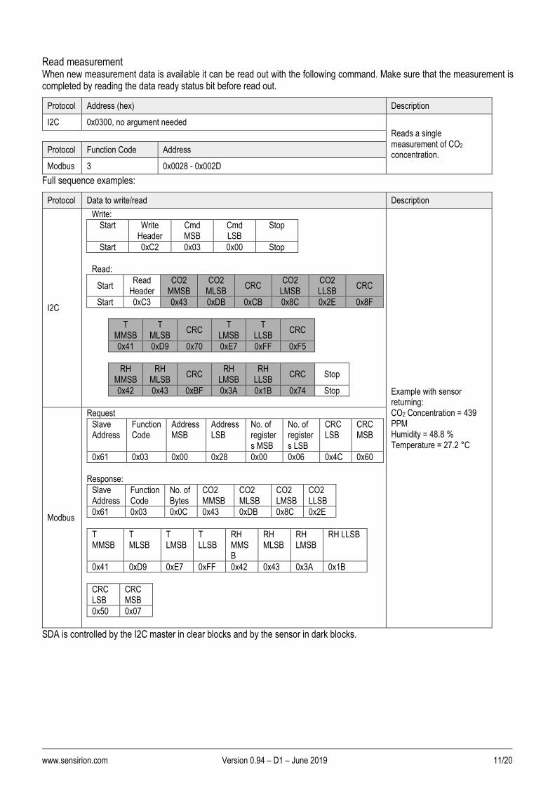
Read measurement When new measurement data is available it can be read out with the following command. Make sure that the measurement is completed by reading the data ready status bit before read out.
Protocol Address (hex) Description
I2C 0x0300, no argument needed
Reads a single measurement of CO2 concentration.
Protocol Function Code Address
Modbus 3 0x0028 - 0x002D
Full sequence examples:
Protocol Data to write/read Description
I2C
Write:
Start Write Header
Cmd MSB
Cmd LSB
Stop
Start 0xC2 0x03 0x00 Stop
Read:
Start Read
Header CO2
MMSB CO2
MLSB CRC
CO2 LMSB
CO2 LLSB
CRC
Start 0xC3 0x43 0xDB 0xCB 0x8C 0x2E 0x8F
T
MMSB T
MLSB CRC
T LMSB
T LLSB
CRC
0x41 0xD9 0x70 0xE7 0xFF 0xF5
RH
MMSB RH
MLSB CRC
RH LMSB
RH LLSB
CRC Stop
0x42 0x43 0xBF 0x3A 0x1B 0x74 Stop
Example with sensor returning: CO2 Concentration = 439 PPM Humidity = 48.8 % Temperature = 27.2 °C
Modbus
Request
Slave Address
Function Code
Address MSB
Address LSB
No. of registers MSB
No. of registers LSB
CRC LSB
CRC MSB
0x61 0x03 0x00 0x28 0x00 0x06 0x4C 0x60
Response:
Slave Address
Function Code
No. of Bytes
CO2 MMSB
CO2 MLSB
CO2 LMSB
CO2 LLSB
0x61 0x03 0x0C 0x43 0xDB 0x8C 0x2E
T MMSB
T MLSB
T LMSB
T LLSB
RH MMSB
RH MLSB
RH LMSB
RH LLSB
0x41 0xD9 0xE7 0xFF 0x42 0x43 0x3A 0x1B
CRC LSB
CRC MSB
0x50 0x07
SDA is controlled by the I2C master in clear blocks and by the sensor in dark blocks.

www.sensirion.com Version 0.94 – D1 – June 2019 12/20
I2C read-out stream:
Table 2 and Table 3 shows the data layout of the data read out from the sensor.
Using I2C for read-out the sensor will stream out the data in the given order.
Preceding Command Consecutive read Description
Read measurement
Byte1: CO2 concentration MMSB Byte2: CO2 concentration MLSB Byte3: CRC Byte4: CO2 concentration LMSB Byte5: CO2 concentration LLSB Byte6: CRC Byte7: Temperature MMSB Byte8: Temperature MLSB Byte9: CRC Byte10: Temperature LMSB Byte11: Temperature LLSB Byte12: CRC Byte13: Humidity MMSB Byte14: Humidity MLSB Byte15: CRC Byte16: Humidity LMSB Byte17: Humidity LLSB Byte18: CRC
Data read-out table for I2C communication. Measurement of CO2 concentration, humidity and temperature has to be finished before read-out.
Table 2: I2C data read-out table. Read-out of measurement data can be aborted by sending a NACK followed by a stop condition after any data byte.
Example: The CO2 concentration 400 ppm corresponds to 0x43c80000 in Big-Endian notation.
Modbus read-out stream:
Words for retrieving CO2 concentration, humidity and temperature can be read out at the following addresses. The words can be read from the sensor in an arbitrary order.
Preceding Command Consecutive read Memory address Description
Read measurement
Word0: CO2 MSW Word1: CO2 LSW Word2: Temperature MSW Word3: Temperature LSW Word4: Humidity MSW Word5: Humidity LSW
0x0028 0x0029 0x002A 0x002B 0x002C 0x002D
Data read-out table for Modbus communication. Measurement of CO2 concentration, humidity and temperature has to be finished before read-out.
Table 3: Modbus data read-out table.
Example: The CO2 concentration 400 ppm corresponds to 0x43c80000 in Big-Endian notation.
www.sensirion.com Version 0.94 – D1 – June 2019 13/20
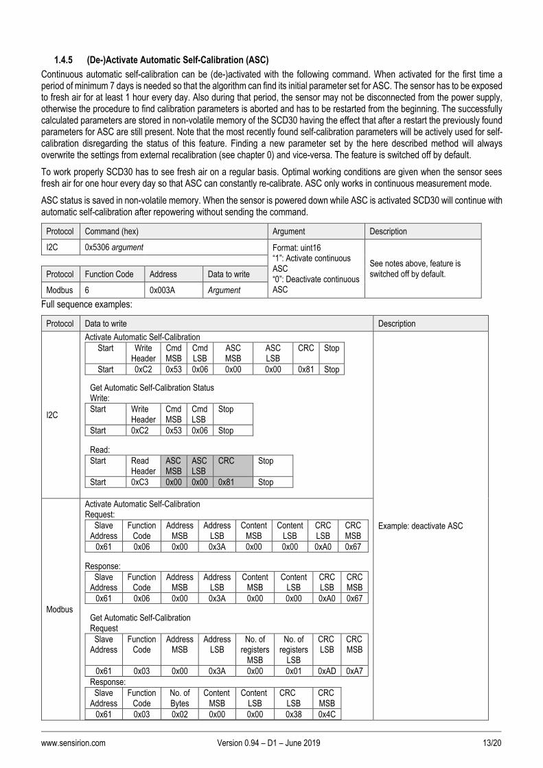
1.4.5 (De-)Activate Automatic Self-Calibration (ASC)
Continuous automatic self-calibration can be (de-)activated with the following command. When activated for the first time a period of minimum 7 days is needed so that the algorithm can find its initial parameter set for ASC. The sensor has to be exposed to fresh air for at least 1 hour every day. Also during that period, the sensor may not be disconnected from the power supply, otherwise the procedure to find calibration parameters is aborted and has to be restarted from the beginning. The successfully calculated parameters are stored in non-volatile memory of the SCD30 having the effect that after a restart the previously found parameters for ASC are still present. Note that the most recently found self-calibration parameters will be actively used for self-calibration disregarding the status of this feature. Finding a new parameter set by the here described method will always overwrite the settings from external recalibration (see chapter 0) and vice-versa. The feature is switched off by default.
To work properly SCD30 has to see fresh air on a regular basis. Optimal working conditions are given when the sensor sees fresh air for one hour every day so that ASC can constantly re-calibrate. ASC only works in continuous measurement mode.
ASC status is saved in non-volatile memory. When the sensor is powered down while ASC is activated SCD30 will continue with automatic self-calibration after repowering without sending the command.
Protocol Command (hex) Argument Description
I2C 0x5306 argument Format: uint16 “1”: Activate continuous ASC “0”: Deactivate continuous ASC
See notes above, feature is switched off by default.
Protocol Function Code Address Data to write
Modbus 6 0x003A Argument
Full sequence examples:
Protocol Data to write Description
I2C
Activate Automatic Self-Calibration
Start Write Header
Cmd MSB
Cmd LSB
ASC MSB
ASC LSB
CRC Stop
Start 0xC2 0x53 0x06 0x00 0x00 0x81 Stop
Get Automatic Self-Calibration Status Write:
Start Write Header
Cmd MSB
Cmd LSB
Stop
Start 0xC2 0x53 0x06 Stop
Read:
Start Read Header
ASC MSB
ASC LSB
CRC Stop
Start 0xC3 0x00 0x00 0x81 Stop
Example: deactivate ASC
Modbus
Activate Automatic Self-Calibration Request:
Slave Address
Function Code
Address MSB
Address LSB
Content MSB
Content LSB
CRC LSB
CRC MSB
0x61 0x06 0x00 0x3A 0x00 0x00 0xA0 0x67
Response:
Slave Address
Function Code
Address MSB
Address LSB
Content MSB
Content LSB
CRC LSB
CRC MSB
0x61 0x06 0x00 0x3A 0x00 0x00 0xA0 0x67
Get Automatic Self-Calibration Request
Slave Address
Function Code
Address MSB
Address LSB
No. of registers
MSB
No. of registers
LSB
CRC LSB
CRC MSB
0x61 0x03 0x00 0x3A 0x00 0x01 0xAD 0xA7
Response:
Slave Address
Function Code
No. of Bytes
Content MSB
Content LSB
CRC LSB
CRC MSB
0x61 0x03 0x02 0x00 0x00 0x38 0x4C

www.sensirion.com Version 0.94 – D1 – June 2019 14/20
Set Forced Recalibration value (FRC) Forced recalibration (FRC) is used to compensate for sensor drifts when a reference value of the CO2 concentration in close proximity to the SCD30 is available. For best results, the sensor has to be run in a stable environment in continuous mode at a measurement rate of 2s for at least two minutes before applying the FRC command and sending the reference value. Setting a reference CO2 concentration by the method described here will always supersede corrections from the ASC (see chapter 1.4.5) and vice-versa. The reference CO2 concentration has to be within the range 400 ppm ≤ cref(CO2) ≤ 2000 ppm.
The FRC method imposes a permanent update of the CO2 calibration curve which persists after repowering the sensor. The most recently used reference value is retained in volatile memory and can be read out with the command sequence given below. After repowering the sensor, the command will return the standard reference value of 400 ppm.
Protocol Command (hex) Argument Description
I2C 0x5204 argument
Format: uint16 CO2 concentration in ppm
See notes above.
Protocol Function Code Address Data to write
Modbus 6 0x0039 Argument
Full sequence examples:
Protocol Data to write Description
I2C
Set Forced Recalibration value
Start Write Header
Cmd MSB
Cmd LSB FRC MSB
FRC LSB
CRC Stop
Start 0xC2 0x52 0x04 0x01 0xC2 0x50 Stop
Get Forced Recalibration value Write:
Start Write Header
Cmd MSB
Cmd LSB Stop
Start 0xC2 0x52 0x04 Stop
Read:
Start Read Header
FRC MSB
FRC LSB CRC Stop
Start 0xC3 0x01 0xC2 0x50 Stop
Example: Set FRC with argument 450 ppm
Modbus
Set Forced Recalibration value Request:
Slave Address
Function Code
Address MSB
Address LSB
Content MSB
Content LSB
CRC LSB
CRC MSB
0x61 0x06 0x00 0x39 0x01 0xC2 0xD0 0x66
Response:
Slave Address
Function Code
Address MSB
Address LSB
Content MSB
Content LSB
CRC LSB
CRC MSB
0x61 0x06 0x00 0x39 0x01 0xC2 0xD0 0x66
Get Forced Recalibration value Request:
Slave Address
Function Code
Address MSB
Address LSB
No. of registers
MSB
No. of registers
LSB
CRC LSB
CRC MSB
0x61 0x03 0x00 0x39 0x00 0x01 0x5D 0xA7
Response:
Slave Address
Function Code
No. of Bytes
Content MSB
Content LSB
CRC LSB
CRC MSB
0x61 0x03 0x02 0x01 0xC2 0xB8 0x4D

www.sensirion.com Version 0.94 – D1 – June 2019 15/20
1.4.6 Set Temperature Offset
The on-board RH/T sensor is influenced by thermal self-heating of SCD30 and other electrical components. Design-in alters the thermal properties of SCD30 such that temperature and humidity offsets may occur when operating the sensor in end-customer devices. Compensation of those effects is achievable by writing the temperature offset found in continuous operation of the device into the sensor.
Temperature offset value is saved in non-volatile memory. The last set value will be used for temperature offset compensation after repowering.
Protocol Command (hex) Argument Description
I2C 0x5403 argument Format: uint16 Temperature offset, unit [°C x 100], i.e. one tick corresponds to 0.01°C
See notes above.
Protocol Function Code Address Data to write
Modbus 6 0x003B argument
Full sequence examples:
Protocol Data to write Description
I2C
Set Temperature Offset Start
Write Header
Cmd MSB
Cmd LSB
SHT Offset MSB
SHT Offset LSB
CRC Stop
Start 0xC2 0x54 0x03 0x01 0xF4 0x33 Stop
Get Temperature Offset Write:
Start Write Header
Cmd MSB
Cmd LSB
Stop
Start 0xC2 0x54 0x03 Stop
Read:
Start Read Header
SHT Offset MSB
SHT Offset LSB
CRC Stop
Start 0xC3 0x01 0xF4 0x33 Stop
Example: Set temperature offset to 5 K
Modbus
Set Temperature Offset Request:
Slave Address
Function Code
Address MSB
Address LSB
Content MSB
Content LSB
CRC LSB
CRC MSB
0x61 0x06 0x00 0x3B 0x01 0xF4 0xF1 0xB0
Response:
Slave Address
Function Code
Address MSB
Address LSB
Content MSB
Content LSB
CRC LSB
CRC MSB
0x61 0x06 0x00 0x3B 0x01 0xF4 0xF1 0xB0
Get Temperature Offset Request:
Slave Address
Function Code
Address MSB
Address LSB
No. of registers
MSB
No. of registers
LSB
CRC LSB
CRC MSB
0x61 0x03 0x00 0x3B 0x00 0x01 0xFC 0x67
Response:
Slave Address
Function Code
No. of Bytes
Content MSB
Content LSB
CRC LSB
CRC MSB
0x61 0x03 0x02 0x01 0xF4 0x38 0x5B
www.sensirion.com Version 0.94 – D1 – June 2019 16/20
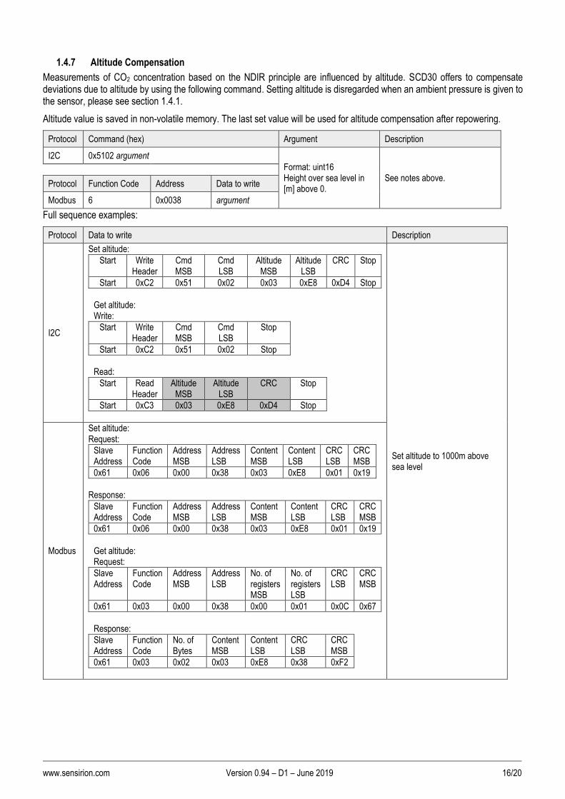
1.4.7 Altitude Compensation
Measurements of CO2 concentration based on the NDIR principle are influenced by altitude. SCD30 offers to compensate deviations due to altitude by using the following command. Setting altitude is disregarded when an ambient pressure is given to the sensor, please see section 1.4.1.
Altitude value is saved in non-volatile memory. The last set value will be used for altitude compensation after repowering.
Protocol Command (hex) Argument Description
I2C 0x5102 argument
Format: uint16 Height over sea level in [m] above 0.
See notes above.
Protocol Function Code Address Data to write
Modbus 6 0x0038 argument
Full sequence examples:
Protocol Data to write Description
I2C
Set altitude:
Start Write Header
Cmd MSB
Cmd LSB
Altitude MSB
Altitude LSB
CRC Stop
Start 0xC2 0x51 0x02 0x03 0xE8 0xD4 Stop
Get altitude: Write:
Start Write Header
Cmd MSB
Cmd LSB
Stop
Start 0xC2 0x51 0x02 Stop
Read:
Start Read Header
Altitude MSB
Altitude LSB
CRC Stop
Start 0xC3 0x03 0xE8 0xD4 Stop
Set altitude to 1000m above sea level
Modbus
Set altitude: Request:
Slave Address
Function Code
Address MSB
Address LSB
Content MSB
Content LSB
CRC LSB
CRC MSB
0x61 0x06 0x00 0x38 0x03 0xE8 0x01 0x19
Response:
Slave Address
Function Code
Address MSB
Address LSB
Content MSB
Content LSB
CRC LSB
CRC MSB
0x61 0x06 0x00 0x38 0x03 0xE8 0x01 0x19
Get altitude: Request:
Slave Address
Function Code
Address MSB
Address LSB
No. of registers MSB
No. of registers LSB
CRC LSB
CRC MSB
0x61 0x03 0x00 0x38 0x00 0x01 0x0C 0x67
Response:
Slave Address
Function Code
No. of Bytes
Content MSB
Content LSB
CRC LSB
CRC MSB
0x61 0x03 0x02 0x03 0xE8 0x38 0xF2

www.sensirion.com Version 0.94 – D1 – June 2019 17/20
1.4.8 Read firmware version
Following command can be used to read out the firmware version of SCD30 module
Protocol Address (hex) Description
I2C 0xD100, no argument needed
Returns the firmware version
Protocol Function Code Address
Modbus 3 0x0020
Full sequence examples:
Protocol Data to write/Read Description
I2C
Write:
Start Write Header
Cmd MSB
Cmd LSB
Stop
Start 0xC2 0xD1 0x00 Stop
Read:
Start Read Header
Firmware version major
Firmware version minor
CRC Stop
Start 0xC3 0x03 0x42 0xF3 Stop
Firmware version: Major.Minor
Modbus
Request
Slave Address
Function Code
Address MSB
Address LSB
No. of registers MSB
No. of registers LSB
CRC LSB
CRC MSB
0x61 0x03 0x00 0x20 0x00 0x01 0x8C 0x60
Response:
Slave Address
Function Code
No. of Bytes
Firmware version major
Firmware version minor
CRC LSB
CRC MSB
0x61 0x03 0x02 0x03 0x42 0xB8 0x8D
I2C: SDA is controlled by the I2C master in clear blocks and by the sensor in dark blocks.

www.sensirion.com Version 0.94 – D1 – June 2019 18/20
1.4.9 Soft reset
The SCD30 provides a soft reset mechanism that forces the sensor into the same state as after powering up without the need for removing the power-supply. It does so by restarting its system controller. After soft reset the sensor will reload all calibrated data. However, it is worth noting that the sensor reloads calibration data prior to every measurement by default. This includes previously set reference values from ASC or FRC as well as temperature offset values last setting.
The sensor is able to receive the command at any time, regardless of its internal state. In order to start the soft reset procedure the following command should be sent.
Protocol Command (hex) Argument Description
I2C 0xD304
Restarts the sensor
Protocol Function Code Address Data to write
Modbus 6 0x0034 0x0001
Full sequence examples:
Protocol Data to write Description
I2C
Start Write
Header Cmd MSB
Cmd LSB
Stop
Start 0xC2 0xD3 0x04 Stop
Restarts the sensor
Modbus
Request:
Slave Address
Function Code
Address MSB
Address LSB
Content MSB
Content LSB
CRC LSB
CRC MSB
0x61 0x06 0x00 0x34 0x00 0x01 0x00 0x64
Response:
Slave Address
Function Code
Address MSB
Address LSB
Content MSB
Content LSB
CRC LSB
CRC MSB
0x61 0x06 0x00 0x34 0x00 0x01 0x00 0x64

www.sensirion.com Version 0.94 – D1 – June 2019 19/20
1.5 Signal conversion to physical values
All data read from the sensor are float numbers in big-endian format2. Conversion of digital values Sx, (x = c(CO2), RH, T) to physical values and respective units are shown in the following table
Physical quantity Conversion formula Units Range
CO2 concentration c(CO2) c(CO2) = Sc(CO2) ppm 0 – 10000
Temperature T T = ST °C -40 – 125°C
Relative humidity RH RH = SRH %RH 0 – 100
Table 4: Signal conversion table.
Conversation of temperature to °F as well as relative humidity to absolute humidity and dew point temperature can be found in Sensirion’s online support center3
Sample pseudo code for converting data read from the sensor to physical value can be found below.
// CO2 concentration
float co2Concentration;
unsigned int tempU32;
// read data is in a buffer. In case of I2C CRCs have been removed
// beforehand. Content of the buffer is the following
unsigned char buffer[4];
buffer[0] = 0x43; // MMSB CO2
buffer[1] = 0xDB; // MLSB CO2
buffer[2] = 0x8C; // LMSB CO2
buffer[3] = 0x2E; // LLSB CO2
// cast 4 bytes to one unsigned 32 bit integer
tempU32 = (unsigned int)((((unsigned int)buffer[0]) << 24) |
(((unsigned int)buffer[1]) << 16) |
(((unsigned int)buffer[2]) << 8) |
((unsigned int)buffer[3]));
// cast unsigned 32 bit integer to 32 bit float
co2Concentration = *(float*)&tempU32; // co2Concentration = 439.09f
2 IEEE 754 applies. 3 https://www.sensirion.com/fileadmin/user_upload/customers/sensirion/Dokumente/2_Humidity_Sensors/Sensirion_Humidity_Sensors_at_a_Glance_V1.pdf

www.sensirion.com Version 0.94 – D1 – June 2019 20/20
2 Important Notices
2.1 Warning, Personal Injury
Do not use this product as safety or emergency stop devices or in any other application where failure of the product could result in personal injury. Do not use this product for applications other than its intended and authorized use. Before installing, handling, using or servicing this product, please consult the data sheet and application notes. Failure to comply with these instructions could result in death or serious injury. If the Buyer shall purchase or use SENSIRION products for any unintended or unauthorized application, Buyer shall defend, indemnify and hold harmless SENSIRION and its officers, employees, subsidiaries, affiliates and distributors against all claims, costs, damages and expenses, and reasonable attorney fees arising out of, directly or indirectly, any claim of personal injury or death associated with such unintended or unauthorized use, even if SENSIRION shall be allegedly negligent with respect to the design or the manufacture of the product.
2.2 ESD Precautions
The inherent design of this component causes it to be sensitive to electrostatic discharge (ESD). To prevent ESD-induced damage and/or degradation, take customary and statutory ESD precautions when handling this product. See application note “ESD, Latchup and EMC” for more information.
2.3 Warranty
SENSIRION warrants solely to the original purchaser of this product for a period of 12 months (one year) from the date of delivery that this product shall be of the quality, material and workmanship defined in SENSIRION’s published specifications of the product. Within such period, if proven to be defective, SENSIRION shall repair and/or replace this product, in SENSIRION’s discretion, free of charge to the Buyer, provided that: ▪ notice in writing describing the defects shall be given to SENSIRION within fourteen (14) days after their appearance; ▪ such defects shall be found, to SENSIRION’s reasonable satisfaction, to have arisen from SENSIRION’s faulty design, material, or workmanship; ▪ the defective product shall be returned to SENSIRION’s factory at the Buyer’s expense; and ▪ the warranty period for any repaired or replaced product shall be limited to the unexpired portion of the original period. This warranty does not apply to any equipment which has not been installed and used within the specifications recommended by SENSIRION for the intended and proper use of the equipment. EXCEPT FOR THE WARRANTIES EXPRESSLY SET FORTH HEREIN, SENSIRION MAKES NO WARRANTIES, EITHER EXPRESS OR IMPLIED, WITH RESPECT TO THE PRODUCT. ANY AND ALL WARRANTIES, INCLUDING WITHOUT LIMITATION, WARRANTIES OF MERCHANTABILITY OR FITNESS FOR A PARTICULAR PURPOSE, ARE EXPRESSLY EXCLUDED AND DECLINED. SENSIRION is only liable for defects of this product arising under the conditions of operation provided for in the data sheet and proper use of the goods. SENSIRION explicitly disclaims all warranties, express or implied, for any period during which the goods are operated or stored not in accordance with the technical specifications. SENSIRION does not assume any liability arising out of any application or use of any product or circuit and specifically disclaims any and all liability, including without limitation consequential or incidental damages. All operating parameters, including without limitation recommended parameters, must be validated for each customer’s applications by customer’s technical experts. Recommended parameters can and do vary in different applications. SENSIRION reserves the right, without further notice, (i) to change the product specifications and/or the information in this document and (ii) to improve reliability, functions and design of this product. Copyright© 2018, by SENSIRION. CMOSens® is a trademark of Sensirion All rights reserved
3 Headquarters and Subsidiaries
Sensirion AG Laubisruetistr. 50 CH-8712 Staefa ZH Switzerland phone: +41 44 306 40 00 fax: +41 44 306 40 30 [email protected] www.sensirion.com
Sensirion Inc., USA phone: +1 312 690 5858 [email protected] www.sensirion.com
Sensirion Korea Co. Ltd. phone: +82 31 337 7700~3 [email protected] www.sensirion.co.kr
Sensirion Japan Co. Ltd. phone: +81 3 3444 4940 [email protected] www.sensirion.co.jp
Sensirion China Co. Ltd. phone: +86 755 8252 1501 [email protected] www.sensirion.com.cn
Sensirion Taiwan Co. Ltd phone: +886 3 5506701 [email protected] www.sensirion.com
To find your local representative, please visit www.sensirion.com/distributors