Embed Size (px)
Citation preview
INSTRUCTION MANUAL
CAUTION: Read All Instructions Before Operating Equipment
MFJ ENTERPRISES, INC.300 Industrial Park RoadStarkville, MS 39759 USA
Tel: 662-323-5869 Fax: 662-323-6551
COPYRIGHT 200 MFJ ENTERPRISES, INC.5C
Model MFJ-993B
VERSION 1A
IntelliTunerAutomatic Antenna Tuner
TM

MFJ-993B IntelliTuner Automatic Antenna Tuner Instruction Manual
© 2003-2005 MFJ Enterprises, Inc. i
Contents
THE BASICS
Introduction...................................................................................................................................... 1 Features............................................................................................................................................ 2 Specifications................................................................................................................................... 2 Fast Start .......................................................................................................................................... 3 Front Panel ....................................................................................................................................... 4
SWR/Wattmeter.................................................................................................................. 4 LCD Display ....................................................................................................................... 4 LCD Contrast Control......................................................................................................... 4 ANT Button ........................................................................................................................ 4 MODE Button..................................................................................................................... 4 C-UP and C-DN Buttons .................................................................................................... 4 L-UP and L-DN Buttons..................................................................................................... 5 AUTO Button ..................................................................................................................... 5 TUNE Button...................................................................................................................... 5 VOL Control ....................................................................................................................... 5 POWER Button................................................................................................................... 5
Back Panel ....................................................................................................................................... 7 Power .................................................................................................................................. 7 Remote Port ........................................................................................................................ 7 Radio Interface.................................................................................................................... 7 Transmitter.......................................................................................................................... 8 Ground ................................................................................................................................ 8 Balanced Line ..................................................................................................................... 9 Wire .................................................................................................................................... 9 Antenna 1............................................................................................................................ 9 Antenna 2............................................................................................................................ 9
Installation ....................................................................................................................................... 9 SWR/Wattmeter............................................................................................................................. 10
THE MENUS
Main Mode Menus......................................................................................................................... 11 Digital Wattmeter Menu ................................................................................................... 11 Power Bar Meter Menu..................................................................................................... 11 SWR Bar Meter Menu ...................................................................................................... 12 L-Network Menu .............................................................................................................. 12
Tuner Indicators ............................................................................................................................. 13 Antenna............................................................................................................................. 13 IntelliTune......................................................................................................................... 13 Memory............................................................................................................................. 13 Power Level ...................................................................................................................... 13 LC Limit ........................................................................................................................... 14 Meter Range...................................................................................................................... 14
MFJ-993B IntelliTuner Automatic Antenna Tuner Instruction Manual
© 2003-2005 MFJ Enterprises, Inc. ii
Auto/Semi ......................................................................................................................... 14 StickyTune........................................................................................................................ 14
Setup Mode Menus ........................................................................................................................ 15 Power Level Menu............................................................................................................ 15 Target SWR Menu ............................................................................................................ 15 Auto Tune SWR Menu ..................................................................................................... 15 Meter Range Menu ........................................................................................................... 16 Peak Hold Menu ............................................................................................................... 16 Memory Menu .................................................................................................................. 16 IntelliTune Menu .............................................................................................................. 17 SWR Beep Menu .............................................................................................................. 17 Beep Menu........................................................................................................................ 17 Refresh Menu.................................................................................................................... 17 LC Limit Menu ................................................................................................................. 18
OPERATION Manual Tuning............................................................................................................................... 18 Meter Codes and Audible Beeps.................................................................................................... 19 Foldback Circuit ............................................................................................................................ 20 Grounding Hints ............................................................................................................................ 21 Antenna System Hints.................................................................................................................... 21
Location ............................................................................................................................ 21 Matching Problems ........................................................................................................... 21
APPENDICES
Resetting the Tuner ........................................................................................................................ 23 Factory Defaults................................................................................................................ 23 Delete Antenna Memory................................................................................................... 24 Total Reset ........................................................................................................................ 24
Self Test ......................................................................................................................................... 24 Power Down Circuit Test............................................................................................................... 25 Relay Test ...................................................................................................................................... 26 Firmware Version Number via Meter............................................................................................ 26 Setting the Speaker Volume........................................................................................................... 26 Wattmeter Calibration.................................................................................................................... 27 SWR Bridge Calibration ................................................................................................................ 27 Frequency Counter Calibration...................................................................................................... 28 In Case of Difficulty ...................................................................................................................... 29 Technical Assistance...................................................................................................................... 29 List of Accessories......................................................................................................................... 29 Circuit Block Diagram................................................................................................................... 30
MFJ-993B IntelliTuner Automatic Antenna Tuner Instruction Manual
© 2003-2005 MFJ Enterprises, Inc. iii
FIGURES Figure 1. Installation Block Diagram.............................................................................................. 3 Figure 2. MFJ-993B Front Panel .................................................................................................... 4 Figure 3. Mode Button Flow Chart and Button Action .................................................................. 6 Figure 4. MFJ-993B Back Panel..................................................................................................... 7 Figure 5. Alinco Interface Cable..................................................................................................... 8 Figure 6. Icom Interface Cable ....................................................................................................... 8 Figure 7. SWR/Wattmeter ............................................................................................................ 10 Figure 8. Power Bar Meter (High Range)..................................................................................... 12 Figure 9. Power Bar Meter (Low Range) ..................................................................................... 12 Figure 10. SWR Bar Meter ........................................................................................................... 12 Figure 11. Main Mode Menus Display ......................................................................................... 13 Figure 12. Tuner Indicators........................................................................................................... 14 Figure 13. Power-On Operations .................................................................................................. 23 Figure 14. MFJ-993B Circuit Block Diagram .............................................................................. 30
TABLES
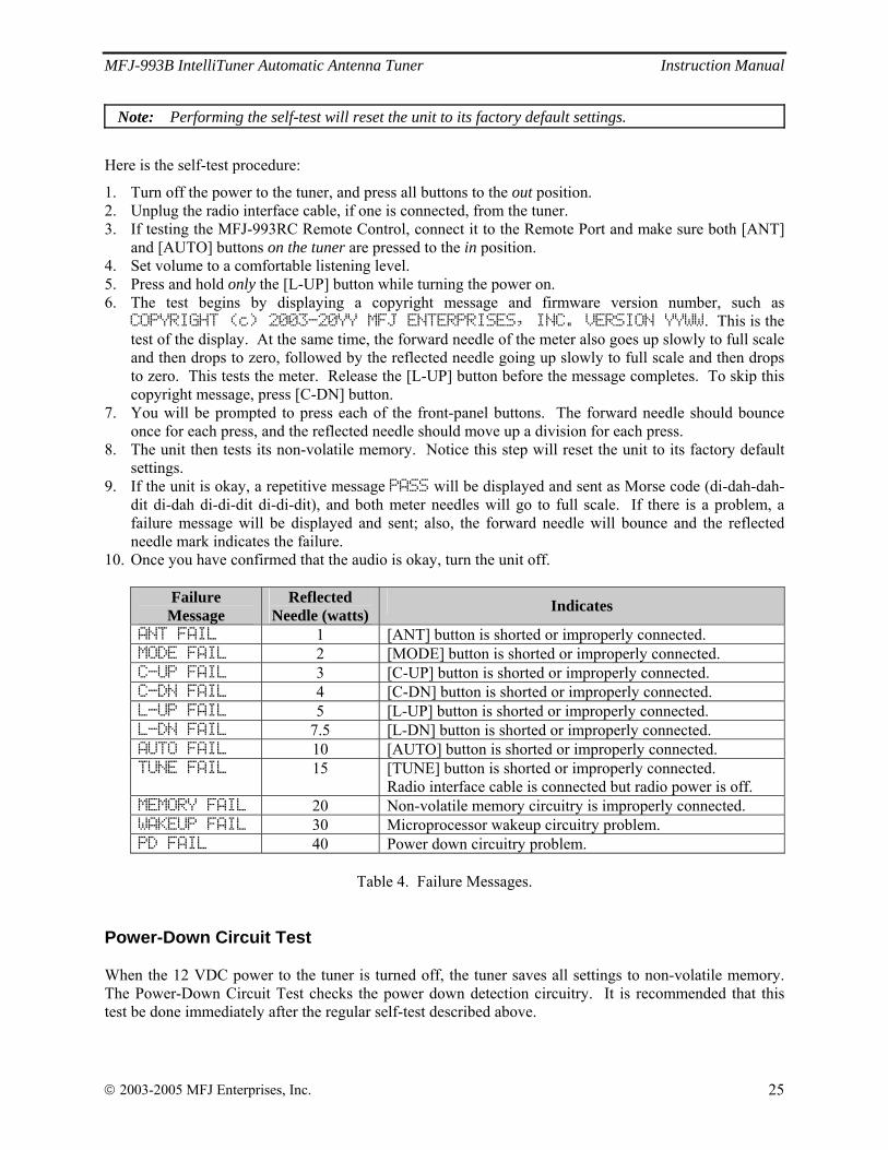
Table 1. Memory Resolution ........................................................................................................ 16 Table 2. Meter Needle Stationary Codes ...................................................................................... 19 Table 3. Meter Needle Bounce Codes .......................................................................................... 20 Table 4. Failure Messages............................................................................................................. 25

MFJ-993B IntelliTuner Automatic Antenna Tuner Instruction Manual
© 2003-2005 MFJ Enterprises, Inc. iv
THIS PAGE IS LEFT BLANK INTENTIONALLY
MFJ-993B IntelliTuner Automatic Antenna Tuner Instruction Manual
© 2003-2005 MFJ Enterprises, Inc. 1
The Basics
Introduction The MFJ-993B IntelliTunerTM lets you rapidly tune any antenna automatically: balanced, unbalanced, or single-wire. The MFJ-993B is a comprehensive automatic antenna tuning center with SWR/wattmeter, antenna switch for two antennas, and a 4:1 current balun for balanced lines. MFJ's exclusive InstantRecallTM, IntelliTuneTM and AdaptiveSearchTM algorithms give you fast automatic tuning with more than 20,000 non-volatile VirtualAntennaTM memories. Each of the two antennas has four banks of memory; each memory bank has over 2500 non-volatile memories for tuner settings. The tuner includes a highly efficient switching L-network with wide matching capability, 1.8 to 30 MHz coverage, cross-needle power meters, backlight LCD display, a port for an accessory remote control, a radio interface port, and heavy-duty 16 amp/1000 volt relays. It is rated at 300 watts to match 6 to 1600 ohms antennas (SWR up to 32:1) or 150 watts to match wider range of 6 to 3200 ohms (SWR up to 64:1). A maximum of 256 values of inductance and 256 values of capacitance are available. With the capacitance switched between the input and output side, this provides a total of 131,072 L/C tuning combinations. The nominal tuning ranges are 0 to 24 μH and 0 to 3900 pF. All MFJ IntelliTunersTM learn and remember. When you transmit, they automatically adjust for minimum SWR and remember the frequency and tuner settings, safely stored in non-volatile memory. The next time you operate on that frequency (or close to it) and antenna, these tuner settings are instantly restored and you’re ready to operate in milliseconds. Each of two antenna selections has four banks of memory, which can learn and remember more than 2500 frequencies and tuner settings per bank. When you key your transmitter, MFJ’s InstantRecallTM checks its memory to see if you have operated that frequency before. If so, tuning is instantaneous and you’re ready to operate. If not, MFJ’s IntelliTuneTM algorithm (based on MFJ’s famous SWR Analyzer technology) kicks in. It measures the complex impedance of your antenna. Next, it calculates the components it needs and instantly snaps them in. Finally, it fine-tunes to minimize SWR, and you’re ready to operate--all in a fraction of a second. If the antenna impedance is not within the tuner’s measurement range, MFJ’s AdaptiveSearchTM algorithm goes into action. Frequency is measured and relevant components values are determined. Only those values are searched for fast tuning. If it still cannot find a match, the search is performed again using a different search pattern. The target SWR can be set at 1.0 through 2.0. The minimum power to tune is approximately two watts. You can manually tune where you can’t transmit (for listening out of ham bands). All MFJ’s IntelliTunersTM support radio tuner interfaces that are compatible with Alinco EDX-2 tuner, Icom AH-3 and AH-4 tuners, Kenwood AT-300 tuner, Yaesu FC-30 tuner, and certain Yaesu radios with CAT system. Optional interface cables MFJ-5124A (for Alinco), MFJ-5124I (for Icom), MFJ-5124K (for Kenwood), MFJ-5124Y and MFJ-5124Y2 (for Yaesu) are available from MFJ Enterprises, Inc. The optional MFJ-993RC Remote Control provides most tuner controls, allowing convenient remote locating of the tuner itself. The tuners enter a “sleep” mode when idle and when no transmit signal is present, turning off the microprocessor clock to avoid the generation of spurious signals.
MFJ-993B IntelliTuner Automatic Antenna Tuner Instruction Manual
© 2003-2005 MFJ Enterprises, Inc. 2
Features
• Automatically matches antennas with impedances of 6 to 1600 ohms or 6 to 3200 ohms • Handles 300 watts (match 6 to 1600 ohms) or 150 watts (match 6 to 3200 ohms) • Tune in less than 15 seconds, usually less than 5 seconds • Over 20,000 non-volatile memories for tuner settings • Four memory banks per antenna with over 2500 memories per bank • Highly efficient switching L-network matching circuit • 1.8 to 30 MHz continuous frequency coverage • Adjustable target SWR 1.0 to 2.0 • Adjustable SWR threshold 0.5 to 1.5 • Lighted cross-needle SWR/wattmeter with high, low, and auto range options • Multifunction backlit LCD display with contrast control • Numeric readings for SWR, forward and reflected power • Bar meters for SWR, forward and reflected power with range options • Audio SWR meter with volume control • Built-in frequency counter • Two SO-239 coax fed antenna connectors • Connector for random wire or single wire antennas • Built-in 4:1 current balun for balanced line antennas • Optional remote control • Optional radio interface for compatible radios Specifications
• Impedance matching range: 6 to 1600 ohms (300 watts) or 6 to 3200 ohms (150 watts) • SWR matching range: up to 8:1 for < 50 ohms and up to 32:1 for > 50 ohms (300 watts) up to 8:1 for < 50 ohms and up to 64:1 for > 50 ohms (150 watts) • Minimum power for tuning: 2 watts • Maximum power while tuning: 100 watts with foldback, 20 watts without foldback • RF power limit: 300 watts SSB/CW • Frequency range: 1.8 to 30 MHz continuous coverage • Frequency counter accuracy: ±1 kHz across HF bands • Frequency counter range: up to 50 MHz • Capacitance range: 0 to 3908 pF nominal (256 values) • Inductance range: 0 to 24.86 μH nominal (256 values) • Relay rating: 16 amp 1000 volts • Relay electrical life: 100,000 operations • Relay mechanical life: 10 million operations • Memory endurance: 1 million erase/write cycles • Memory data retention: > 200 years • Power requirements: 12 - 15 volts DC, 2.1 × 5.5 mm coaxial plug, center pin positive • Current consumption: 1 amp or less • Dimensions (approx.): 10.1 × 2.8 × 9.2 in. (257 × 71 × 234 mm) (width/height/depth) not including connectors • Weight (approx.): 3.9 lb (1.77 kg)
† Specifications and design are subject to change without notice.
MFJ-993B IntelliTuner Automatic Antenna Tuner Instruction Manual
© 2003-2005 MFJ Enterprises, Inc. 3
Fast Start
WARNING
● Never operate the tuner with its cover removed. Contact with the components inside the tuner while transmitting will result in painful RF burns.
● Locate the tuner so that the rear terminals are not accessible during operation. The single wire and balanced line connection may have high voltage while transmitting.
● Disconnect all antennas from the tuner during lightning storms. ● Always tune with low power (about 10 watts). Apply maximum power only after tuning up. ● Never exceed tuner specifications. ● Do not transmit with a high SWR for extended periods of time.
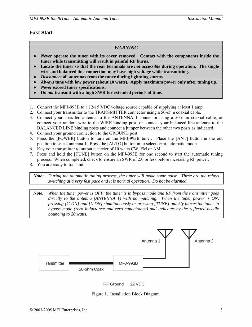
1. Connect the MFJ-993B to a 12-15 VDC voltage source capable of supplying at least 1 amp. 2. Connect your transmitter to the TRANSMITTER connector using a 50-ohm coaxial cable. 3. Connect your coax-fed antenna to the ANTENNA 1 connector using a 50-ohm coaxial cable, or
connect your random wire to the WIRE binding post, or connect your balanced line antenna to the BALANCED LINE binding posts and connect a jumper between the other two posts as indicated.
4. Connect your ground connection to the GROUND post. 5. Press the [POWER] button to turn on the MFJ-993B tuner. Place the [ANT] button in the out
position to select antenna 1. Press the [AUTO] button in to select semi-automatic mode. 6. Key your transmitter to output a carrier of 10 watts CW, FM or AM. 7. Press and hold the [TUNE] button on the MFJ-993B for one second to start the automatic tuning
process. When completed, check to ensure an SWR of 2.0 or less before increasing RF power. 8. You are ready to transmit.
Note: During the automatic tuning process, the tuner will make some noise. These are the relays switching at a very fast pace and it is normal operation. Do not be alarmed.
Note: When the tuner power is OFF, the tuner is in bypass mode and RF from the transmitter goes
directly to the antenna (ANTENNA 1) with no matching. When the tuner power is ON, pressing [C-DN] and [L-DN] simultaneously or pressing [TUNE] quickly places the tuner in bypass mode (zero inductance and zero capacitance) and indicates by the reflected needle bouncing to 20 watts.
Transmitter MFJ-993B50-ohm Coax
Antenna 1
RF Ground 12 VDC
Antenna 2
Figure 1. Installation Block Diagram.
MFJ-993B IntelliTuner Automatic Antenna Tuner Instruction Manual
© 2003-2005 MFJ Enterprises, Inc. 4
Front Panel
0
1030
50
100200 300
0
5
204060
8 5.0
3.0 2.0
1.5 1.2 Hi x1Lo x.1400-3083 1
10
MODELMFJ-993B
ANT C-UP L-UP AUTO POWER
MODE C-DN L-DN TUNE
LCD VOL
AUTOMATIC ANTENNA TUNERMFJ IntelliTunerTM
Dual Power Level300/150 Watts
Z
BYPASS
SWR
14.100MHz 1.1
FWD=100 REF=0.5
1 1.2 1.5 2 3SWR0 25 50 75 100PWR 300
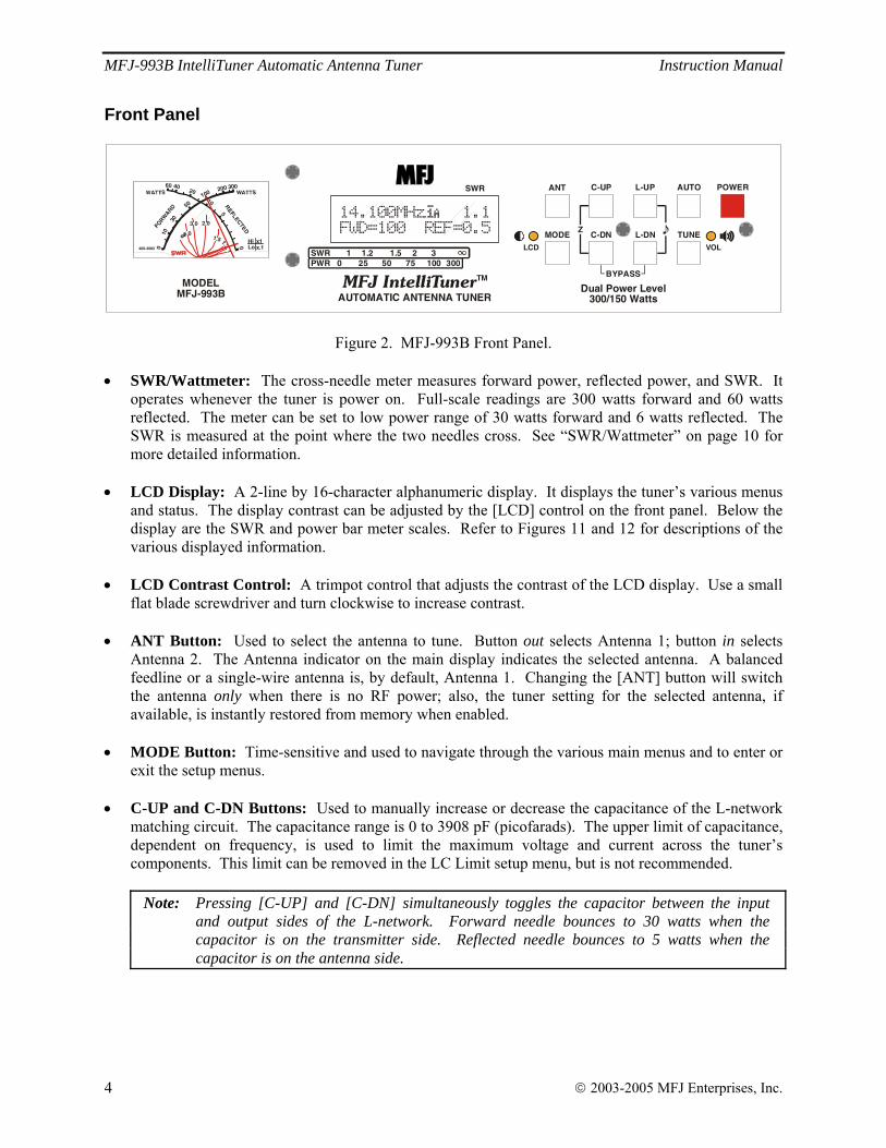
Figure 2. MFJ-993B Front Panel. • SWR/Wattmeter: The cross-needle meter measures forward power, reflected power, and SWR. It
operates whenever the tuner is power on. Full-scale readings are 300 watts forward and 60 watts reflected. The meter can be set to low power range of 30 watts forward and 6 watts reflected. The SWR is measured at the point where the two needles cross. See “SWR/Wattmeter” on page 10 for more detailed information.
• LCD Display: A 2-line by 16-character alphanumeric display. It displays the tuner’s various menus
and status. The display contrast can be adjusted by the [LCD] control on the front panel. Below the display are the SWR and power bar meter scales. Refer to Figures 11 and 12 for descriptions of the various displayed information.
• LCD Contrast Control: A trimpot control that adjusts the contrast of the LCD display. Use a small
flat blade screwdriver and turn clockwise to increase contrast. • ANT Button: Used to select the antenna to tune. Button out selects Antenna 1; button in selects
Antenna 2. The Antenna indicator on the main display indicates the selected antenna. A balanced feedline or a single-wire antenna is, by default, Antenna 1. Changing the [ANT] button will switch the antenna only when there is no RF power; also, the tuner setting for the selected antenna, if available, is instantly restored from memory when enabled.
• MODE Button: Time-sensitive and used to navigate through the various main menus and to enter or
exit the setup menus. • C-UP and C-DN Buttons: Used to manually increase or decrease the capacitance of the L-network
matching circuit. The capacitance range is 0 to 3908 pF (picofarads). The upper limit of capacitance, dependent on frequency, is used to limit the maximum voltage and current across the tuner’s components. This limit can be removed in the LC Limit setup menu, but is not recommended.
Note: Pressing [C-UP] and [C-DN] simultaneously toggles the capacitor between the input
and output sides of the L-network. Forward needle bounces to 30 watts when the capacitor is on the transmitter side. Reflected needle bounces to 5 watts when the capacitor is on the antenna side.
MFJ-993B IntelliTuner Automatic Antenna Tuner Instruction Manual
© 2003-2005 MFJ Enterprises, Inc. 5
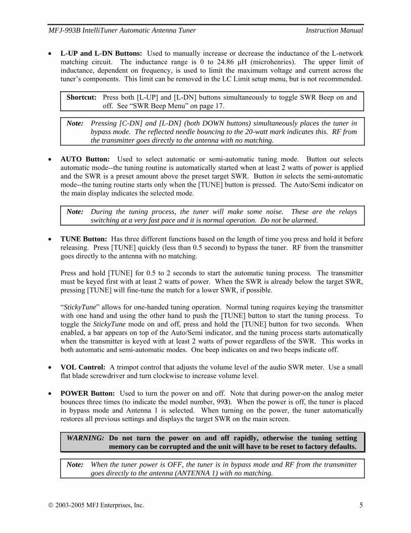
• L-UP and L-DN Buttons: Used to manually increase or decrease the inductance of the L-network matching circuit. The inductance range is 0 to 24.86 μH (microhenries). The upper limit of inductance, dependent on frequency, is used to limit the maximum voltage and current across the tuner’s components. This limit can be removed in the LC Limit setup menu, but is not recommended.
Shortcut: Press both [L-UP] and [L-DN] buttons simultaneously to toggle SWR Beep on and
off. See “SWR Beep Menu” on page 17.
Note: Pressing [C-DN] and [L-DN] (both DOWN buttons) simultaneously places the tuner in bypass mode. The reflected needle bouncing to the 20-watt mark indicates this. RF from the transmitter goes directly to the antenna with no matching.
• AUTO Button: Used to select automatic or semi-automatic tuning mode. Button out selects
automatic mode--the tuning routine is automatically started when at least 2 watts of power is applied and the SWR is a preset amount above the preset target SWR. Button in selects the semi-automatic mode--the tuning routine starts only when the [TUNE] button is pressed. The Auto/Semi indicator on the main display indicates the selected mode.
Note: During the tuning process, the tuner will make some noise. These are the relays
switching at a very fast pace and it is normal operation. Do not be alarmed. • TUNE Button: Has three different functions based on the length of time you press and hold it before
releasing. Press [TUNE] quickly (less than 0.5 second) to bypass the tuner. RF from the transmitter goes directly to the antenna with no matching.
Press and hold [TUNE] for 0.5 to 2 seconds to start the automatic tuning process. The transmitter must be keyed first with at least 2 watts of power. When the SWR is already below the target SWR, pressing [TUNE] will fine-tune the match for a lower SWR, if possible.
“StickyTune” allows for one-handed tuning operation. Normal tuning requires keying the transmitter with one hand and using the other hand to push the [TUNE] button to start the tuning process. To toggle the StickyTune mode on and off, press and hold the [TUNE] button for two seconds. When enabled, a bar appears on top of the Auto/Semi indicator, and the tuning process starts automatically when the transmitter is keyed with at least 2 watts of power regardless of the SWR. This works in both automatic and semi-automatic modes. One beep indicates on and two beeps indicate off.
• VOL Control: A trimpot control that adjusts the volume level of the audio SWR meter. Use a small
flat blade screwdriver and turn clockwise to increase volume level. • POWER Button: Used to turn the power on and off. Note that during power-on the analog meter
bounces three times (to indicate the model number, 993). When the power is off, the tuner is placed in bypass mode and Antenna 1 is selected. When turning on the power, the tuner automatically restores all previous settings and displays the target SWR on the main screen.
WARNING: Do not turn the power on and off rapidly, otherwise the tuning setting memory can be corrupted and the unit will have to be reset to factory defaults.
Note: When the tuner power is OFF, the tuner is in bypass mode and RF from the transmitter goes directly to the antenna (ANTENNA 1) with no matching.
MFJ-993B IntelliTuner Automatic Antenna Tuner Instruction Manual
© 2003-2005 MFJ Enterprises, Inc. 6
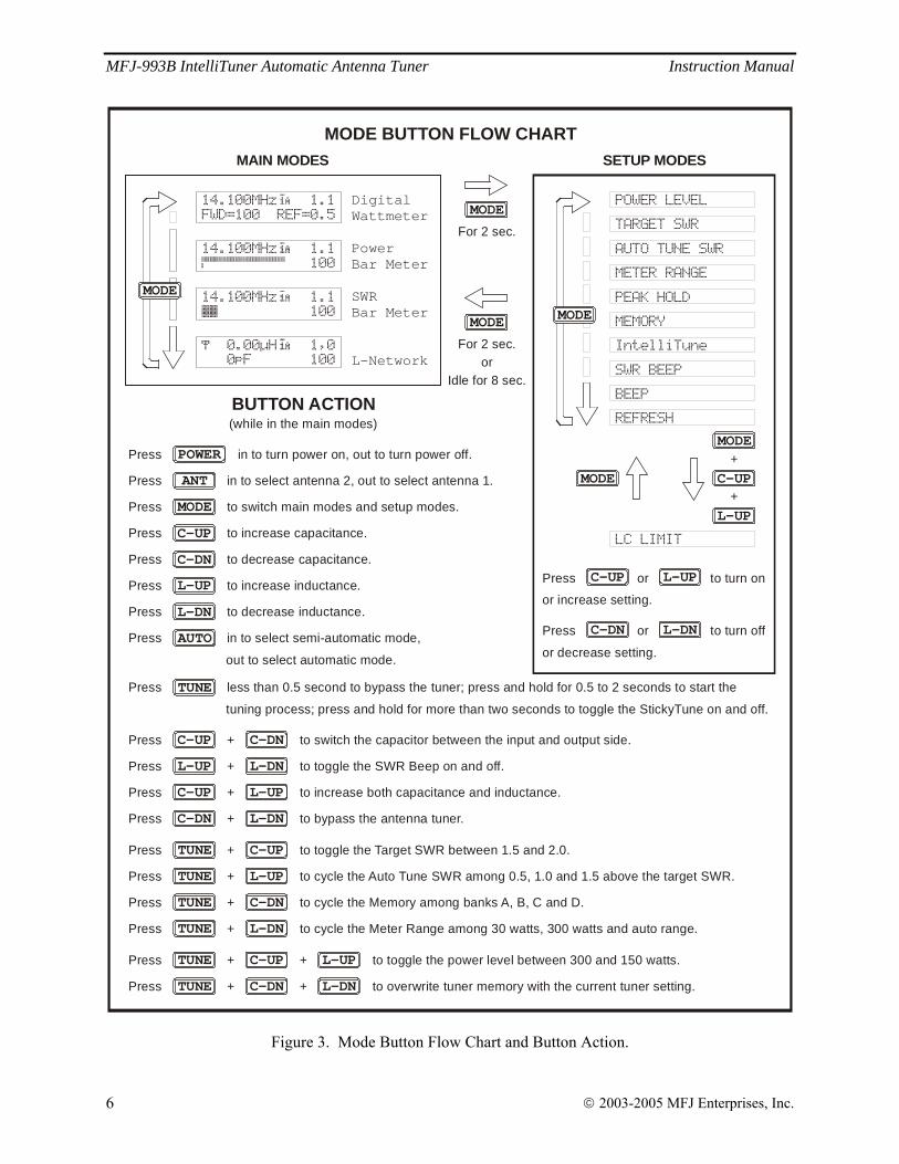
MODE BUTTON FLOW CHARTSETUP MODESMAIN MODES
For 2 sec.
MODE
For 2 sec.or
Idle for 8 sec.
MODE
TUNE C-UP
L-UPTUNE
C-DN L-DN
L-DNL-UP
C-UP C-DNPress + to switch the capacitor between the input and output side.
Press + to toggle the SWR Beep on and off.
Press + to bypass the antenna tuner.
Press + to cycle the Auto Tune SWR among 0.5, 1.0 and 1.5 above the target SWR.
Press + to toggle the Target SWR between 1.5 and 2.0.
TUNE C-DNPress + to cycle the Memory among banks A, B, C and D.
TUNE L-DNPress + to cycle the Meter Range among 30 watts, 300 watts and auto range.
BUTTON ACTION
Press + to increase both capacitance and inductance.C-UP L-UP
MODE
AUTO
ANT
C-UP
L-UP
C-DN
L-DN
TUNE
POWER
Press less than 0.5 second to bypass the tuner; press and hold for 0.5 to 2 seconds to start the
tuning process; press and hold for more than two seconds to toggle the StickyTune on and off.
Press in to select semi-automatic mode,
out to select automatic mode.
Press to decrease inductance.
Press to increase inductance.
Press to decrease capacitance.
Press to increase capacitance.
Press to switch main modes and setup modes.
Press in to select antenna 2, out to select antenna 1.
Press in to turn power on, out to turn power off.
Press or to turn on
or increase setting.
C-UP L-UP
C-DN L-DNPress or to turn off
or decrease setting.
(while in the main modes)
Press + to overwrite tuner memory with the current tuner setting.+ TUNE L-DNC-DN
Press + to + toggle the power level between 300 and 150 watts.TUNE C-UP L-UP
DigitalWattmeter
PowerBar Meter
SWRBar Meter
L-Network
MODE
14.100MHz 1.1
FWD=100 REF=0.5
14.100MHz 1.1
100
0.00uH 1,0
0pF 100
14.100MHz 1.1
100
POWER LEVEL
TARGET SWR
AUTO TUNE SWR
METER RANGE
PEAK HOLD
MEMORY
IntelliTune
SWR BEEP
BEEP
REFRESH
LC LIMIT
MODE
MODE+
MODE
C-UP
L-UP+
Figure 3. Mode Button Flow Chart and Button Action.
MFJ-993B IntelliTuner Automatic Antenna Tuner Instruction Manual
© 2003-2005 MFJ Enterprises, Inc. 7
Back Panel
RADIOINTERFACE
+
POWER12VDC
1A
REMOTEPORT
ANTENNA 1 ANTENNA 2TRANSMITTER
BALANCED LINE
GROUND
WIRE
MFJ ENTERPRISES, INC.STARKVILLE, MS USA
! Do not connect WIRE andANTENNA 1 at same time!Install Jumper When Using
BALANCED LINE Antenna*
*
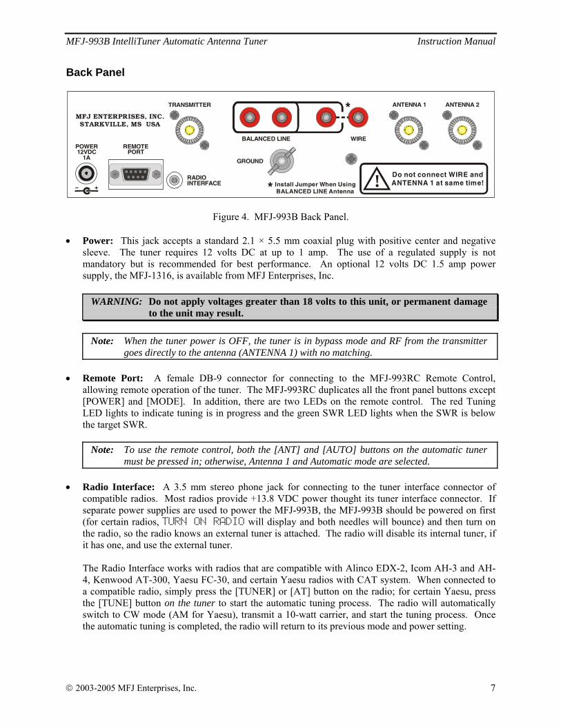
Figure 4. MFJ-993B Back Panel. • Power: This jack accepts a standard 2.1 × 5.5 mm coaxial plug with positive center and negative
sleeve. The tuner requires 12 volts DC at up to 1 amp. The use of a regulated supply is not mandatory but is recommended for best performance. An optional 12 volts DC 1.5 amp power supply, the MFJ-1316, is available from MFJ Enterprises, Inc.
WARNING: Do not apply voltages greater than 18 volts to this unit, or permanent damage to the unit may result.
Note: When the tuner power is OFF, the tuner is in bypass mode and RF from the transmitter
goes directly to the antenna (ANTENNA 1) with no matching.
• Remote Port: A female DB-9 connector for connecting to the MFJ-993RC Remote Control, allowing remote operation of the tuner. The MFJ-993RC duplicates all the front panel buttons except [POWER] and [MODE]. In addition, there are two LEDs on the remote control. The red Tuning LED lights to indicate tuning is in progress and the green SWR LED lights when the SWR is below the target SWR.
Note: To use the remote control, both the [ANT] and [AUTO] buttons on the automatic tuner must be pressed in; otherwise, Antenna 1 and Automatic mode are selected.
• Radio Interface: A 3.5 mm stereo phone jack for connecting to the tuner interface connector of
compatible radios. Most radios provide +13.8 VDC power thought its tuner interface connector. If separate power supplies are used to power the MFJ-993B, the MFJ-993B should be powered on first (for certain radios, TURN ON RADIO will display and both needles will bounce) and then turn on the radio, so the radio knows an external tuner is attached. The radio will disable its internal tuner, if it has one, and use the external tuner. The Radio Interface works with radios that are compatible with Alinco EDX-2, Icom AH-3 and AH-4, Kenwood AT-300, Yaesu FC-30, and certain Yaesu radios with CAT system. When connected to a compatible radio, simply press the [TUNER] or [AT] button on the radio; for certain Yaesu, press the [TUNE] button on the tuner to start the automatic tuning process. The radio will automatically switch to CW mode (AM for Yaesu), transmit a 10-watt carrier, and start the tuning process. Once the automatic tuning is completed, the radio will return to its previous mode and power setting.
MFJ-993B IntelliTuner Automatic Antenna Tuner Instruction Manual
© 2003-2005 MFJ Enterprises, Inc. 8
WARNING: Make sure the +13.8 volts connection on the radio’s tuner port is capable of supplying at least 1 amp of current, since the MFJ-993B uses up to 1 amp.
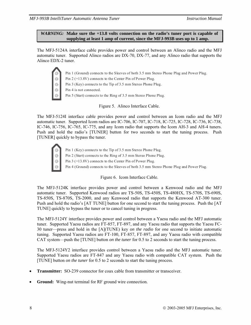
The MFJ-5124A interface cable provides power and control between an Alinco radio and the MFJ automatic tuner. Supported Alinco radios are DX-70, DX-77, and any Alinco radio that supports the Alinco EDX-2 tuner.
Pin 3 (Key) connects to the Tip of 3.5 mm Stereo Phone Plug.
Pin 5 (Start) connects to the Ring of 3.5 mm Stereo Phone Plug.
Pin 2 (+13.8V) connects to the Center Pin of Power Plug.Pin 1 (Ground) connects to the Sleeves of both 3.5 mm Stereo Phone Plug and Power Plug.
Pin 4 is not connected.
Figure 5. Alinco Interface Cable.
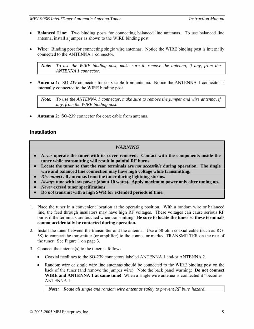
The MFJ-5124I interface cable provides power and control between an Icom radio and the MFJ automatic tuner. Supported Icom radios are IC-706, IC-707, IC-718, IC-725, IC-728, IC-736, IC-738, IC-746, IC-756, IC-765, IC-775, and any Icom radio that supports the Icom AH-3 and AH-4 tuners. Push and hold the radio’s [TUNER] button for two seconds to start the tuning process. Push [TUNER] quickly to bypass the tuner.
Pin 1 (Key) connects to the Tip of 3.5 mm Stereo Phone Plug.Pin 2 (Start) connects to the Ring of 3.5 mm Stereo Phone Plug.Pin 3 (+13.8V) connects to the Center Pin of Power Plug.Pin 4 (Ground) connects to the Sleeves of both 3.5 mm Stereo Phone Plug and Power Plug.
Figure 6. Icom Interface Cable.
The MFJ-5124K interface provides power and control between a Kenwood radio and the MFJ automatic tuner. Supported Kenwood radios are TS-50S, TS-450S, TS-480HX, TS-570S, TS-690S, TS-850S, TS-870S, TS-2000, and any Kenwood radio that supports the Kenwood AT-300 tuner. Push and hold the radio’s [AT TUNE] button for one second to start the tuning process. Push the [AT TUNE] quickly to bypass the tuner or to cancel tuning in progress. The MFJ-5124Y interface provides power and control between a Yaesu radio and the MFJ automatic tuner. Supported Yaesu radios are FT-857, FT-897, and any Yaesu radio that supports the Yaesu FC-30 tuner—press and hold in the [A](TUNE) key on the radio for one second to initiate automatic tuning. Supported Yaesu radios are FT-100, FT-857, FT-897, and any Yaesu radio with compatible CAT system—push the [TUNE] button on the tuner for 0.5 to 2 seconds to start the tuning process. The MFJ-5124Y2 interface provides control between a Yaesu radio and the MFJ automatic tuner. Supported Yaesu radios are FT-847 and any Yaesu radio with compatible CAT system. Push the [TUNE] button on the tuner for 0.5 to 2 seconds to start the tuning process.
• Transmitter: SO-239 connector for coax cable from transmitter or transceiver. • Ground: Wing-nut terminal for RF ground wire connection.
MFJ-993B IntelliTuner Automatic Antenna Tuner Instruction Manual
© 2003-2005 MFJ Enterprises, Inc. 9
• Balanced Line: Two binding posts for connecting balanced line antennas. To use balanced line antenna, install a jumper as shown to the WIRE binding post.
• Wire: Binding post for connecting single wire antennas. Notice the WIRE binding post is internally
connected to the ANTENNA 1 connector.
Note: To use the WIRE binding post, make sure to remove the antenna, if any, from the ANTENNA 1 connector.
• Antenna 1: SO-239 connector for coax cable from antenna. Notice the ANTENNA 1 connector is
internally connected to the WIRE binding post.
Note: To use the ANTENNA 1 connector, make sure to remove the jumper and wire antenna, if any, from the WIRE binding post.
• Antenna 2: SO-239 connector for coax cable from antenna. Installation
WARNING
● Never operate the tuner with its cover removed. Contact with the components inside the tuner while transmitting will result in painful RF burns.
● Locate the tuner so that the rear terminals are not accessible during operation. The single wire and balanced line connection may have high voltage while transmitting.
● Disconnect all antennas from the tuner during lightning storms. ● Always tune with low power (about 10 watts). Apply maximum power only after tuning up. ● Never exceed tuner specifications. ● Do not transmit with a high SWR for extended periods of time.
1. Place the tuner in a convenient location at the operating position. With a random wire or balanced
line, the feed through insulators may have high RF voltages. These voltages can cause serious RF burns if the terminals are touched when transmitting. Be sure to locate the tuner so these terminals cannot accidentally be contacted during operation.
2. Install the tuner between the transmitter and the antenna. Use a 50-ohm coaxial cable (such as RG-58) to connect the transmitter (or amplifier) to the connector marked TRANSMITTER on the rear of the tuner. See Figure 1 on page 3.
3. Connect the antenna(s) to the tuner as follows:
• Coaxial feedlines to the SO-239 connectors labeled ANTENNA 1 and/or ANTENNA 2.
• Random wire or single wire line antennas should be connected to the WIRE binding post on the back of the tuner (and remove the jumper wire). Note the back panel warning: Do not connect WIRE and ANTENNA 1 at same time! When a single wire antenna is connected it “becomes” ANTENNA 1.
Note: Route all single and random wire antennas safely to prevent RF burn hazard.
MFJ-993B IntelliTuner Automatic Antenna Tuner Instruction Manual
© 2003-2005 MFJ Enterprises, Inc. 10
• For a balanced feedline (open wire, twinlead, or twin-axial lines), place a jumper wire as indicated on the back panel and connect the balanced feedline to the BALANCED LINE binding posts. This antenna becomes ANTENNA 1. See “Antenna System Hints” on page 21.
4. A GROUND post is provided for an RF ground connection. See “Grounding Hints” on page 21.
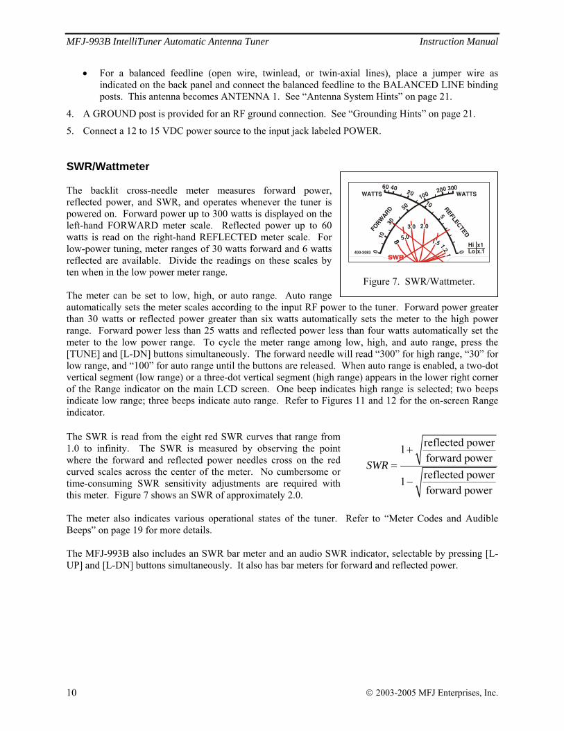
5. Connect a 12 to 15 VDC power source to the input jack labeled POWER. SWR/Wattmeter The backlit cross-needle meter measures forward power, reflected power, and SWR, and operates whenever the tuner is powered on. Forward power up to 300 watts is displayed on the left-hand FORWARD meter scale. Reflected power up to 60 watts is read on the right-hand REFLECTED meter scale. For low-power tuning, meter ranges of 30 watts forward and 6 watts reflected are available. Divide the readings on these scales by ten when in the low power meter range. The meter can be set to low, high, or auto range. Auto range automatically sets the meter scales according to the input RF power to the tuner. Forward power greater than 30 watts or reflected power greater than six watts automatically sets the meter to the high power range. Forward power less than 25 watts and reflected power less than four watts automatically set the meter to the low power range. To cycle the meter range among low, high, and auto range, press the [TUNE] and [L-DN] buttons simultaneously. The forward needle will read “300” for high range, “30” for low range, and “100” for auto range until the buttons are released. When auto range is enabled, a two-dot vertical segment (low range) or a three-dot vertical segment (high range) appears in the lower right corner of the Range indicator on the main LCD screen. One beep indicates high range is selected; two beeps indicate low range; three beeps indicate auto range. Refer to Figures 11 and 12 for the on-screen Range indicator. The SWR is read from the eight red SWR curves that range from 1.0 to infinity. The SWR is measured by observing the point where the forward and reflected power needles cross on the red curved scales across the center of the meter. No cumbersome or time-consuming SWR sensitivity adjustments are required with this meter. Figure 7 shows an SWR of approximately 2.0. The meter also indicates various operational states of the tuner. Refer to “Meter Codes and Audible Beeps” on page 19 for more details. The MFJ-993B also includes an SWR bar meter and an audio SWR indicator, selectable by pressing [L-UP] and [L-DN] buttons simultaneously. It also has bar meters for forward and reflected power.
0
1030
50100
200 300
0
5
204060
8 5.0
3.0 2.0
1.5 1.2 Hi x1Lo x.1400-3083 1
10
Figure 7. SWR/Wattmeter.
reflected power1forward powerreflected power1forward power
SWR+
=−
MFJ-993B IntelliTuner Automatic Antenna Tuner Instruction Manual
© 2003-2005 MFJ Enterprises, Inc. 11
The Menus
Main Mode Menus The main mode menus show various tuner settings and status. There are four main mode menus arranged in a “wrap-around” structure. When powered on, tuner operation starts with the main menu that was last used. Within each main menu, press the [MODE] button briefly to view the next main menu. Press and hold the [MODE] button for two seconds to enter the setup mode (see below). Various tuner indicators are shown on all four main menus: Antenna 1/2, IntelliTuneTM, Memory, Power Level, LC Limit, Meter Range, Auto/Semi, and StickyTuneTM. Refer to Figures 11 and 12 for details on the displayed information.
Note: In sideband mode, the frequency readout on the tuner display jumps around to different frequencies while transmitting and stops on another frequency when un-keyed. This is normal and is a characteristic of sideband mode, because sideband signals jump up and down in frequency and power.
Note: In bypass mode, the decimal point in the SWR reading is replaced with a comma.
Digital Wattmeter Menu
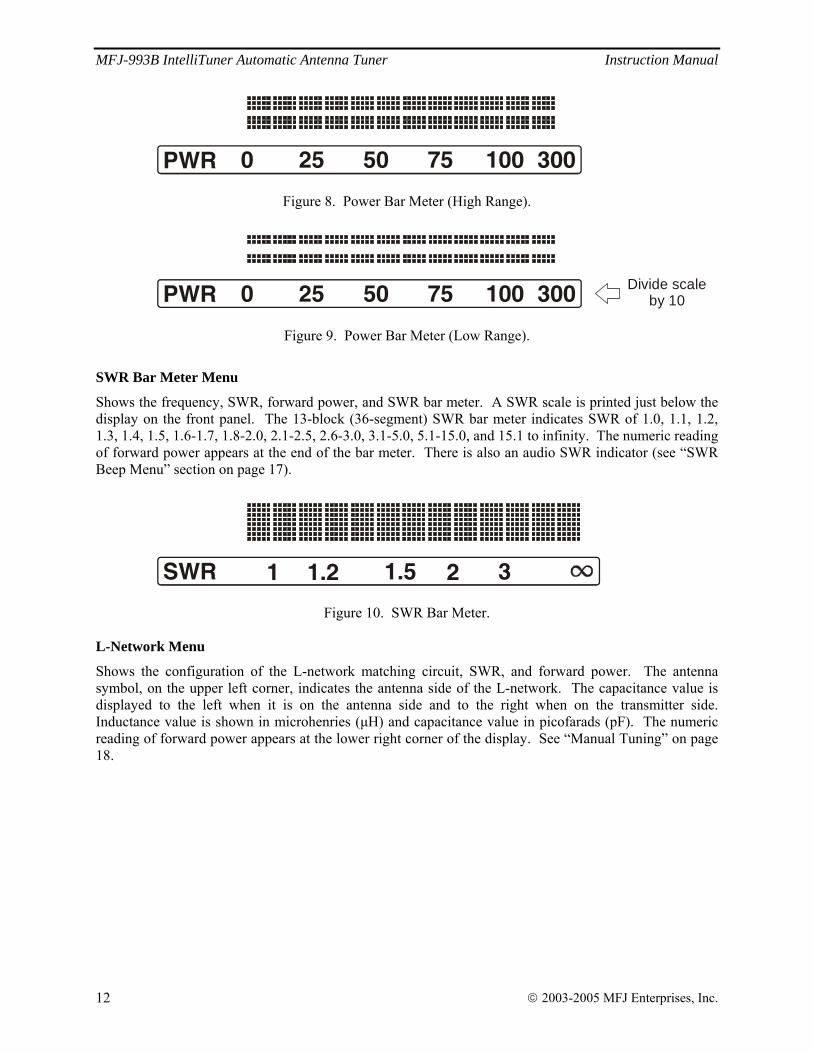
Shows the frequency, SWR, and forward and reflected power in watts. Power Bar Meter Menu
Shows the frequency, SWR, forward power, and bar meters for forward and reflected power. The top bar meter is the forward power and the bottom bar meter is the reflected power. The numeric reading of forward power appears at the end of the bar meters. A power scale is printed just below the display on the front panel. Each power bar meter is consisted of 60 bar segments. When in the high power range, each vertical bar segment consists of three dots. Below 100 watts, each bar segment represents two watts; above 100 watts, each bar segment represents 20 watts. The forward bar meter has a “peak hold” feature. The peak meter hold function freezes the highest displayed bar segment of the forward power for about one second, so that you can more easily read the meter. This function can be turned ON and OFF in the Peak Hold setup mode. For low-power tuning, meter range of 30 watts is available. When in the low power range, divide the readings on the printed power scale by ten and each vertical bar segment consists of two dots. Below 10 watts, each bar segment represents 0.2 watt; above 10 watts, each bar segment represents two watts. Refer to the “SWR/Wattmeter” section on page 10 for more details on power range. The power meter can be set to auto range. Auto range automatically sets the meter scale according to the input RF power to the tuner. Forward power greater than 30 watts or reflected power greater than six watts automatically sets the meter to the high power range. Forward power less than 25 watts and reflected power less than four watts automatically set the meter to the low power range. When auto range is enabled, a two-dot vertical segment appears on the on-screen tuner indicator. Refer to Figures 11 and 12 for the on-screen Range indicator.
MFJ-993B IntelliTuner Automatic Antenna Tuner Instruction Manual
© 2003-2005 MFJ Enterprises, Inc. 12
0 25 50 75 100PWR 300
Figure 8. Power Bar Meter (High Range).
0 25 50 75 100PWR 300 Divide scaleby 10
Figure 9. Power Bar Meter (Low Range).
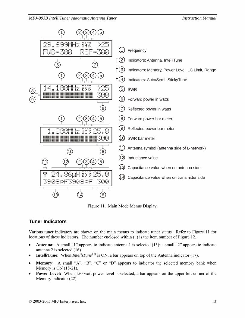
SWR Bar Meter Menu
Shows the frequency, SWR, forward power, and SWR bar meter. A SWR scale is printed just below the display on the front panel. The 13-block (36-segment) SWR bar meter indicates SWR of 1.0, 1.1, 1.2, 1.3, 1.4, 1.5, 1.6-1.7, 1.8-2.0, 2.1-2.5, 2.6-3.0, 3.1-5.0, 5.1-15.0, and 15.1 to infinity. The numeric reading of forward power appears at the end of the bar meter. There is also an audio SWR indicator (see “SWR Beep Menu” section on page 17).
1 1.2 1.5 2 3SWR
Figure 10. SWR Bar Meter.
L-Network Menu
Shows the configuration of the L-network matching circuit, SWR, and forward power. The antenna symbol, on the upper left corner, indicates the antenna side of the L-network. The capacitance value is displayed to the left when it is on the antenna side and to the right when on the transmitter side. Inductance value is shown in microhenries (μH) and capacitance value in picofarads (pF). The numeric reading of forward power appears at the lower right corner of the display. See “Manual Tuning” on page 18.
MFJ-993B IntelliTuner Automatic Antenna Tuner Instruction Manual
© 2003-2005 MFJ Enterprises, Inc. 13
Frequency
Indicators: Antenna, IntelliTune
Indicators:
SWR
Forward power in watts
Reflected power in watts
Forward power bar meter
Reflected power bar meter
SWR bar meter
Antenna symbol (antenna side of L-network)
Inductance value
Capacitance value when on antenna side
Capacitance value when on transmitter side
Memory, Power Level, LC Limit, Range
Indicators: Auto/Semi, StickyTune
1
2
3
4
5
6
7
8
9
10
11
12
13
14
6 7
1 2 3 4 5
8
9
1 2 3 4 5
6
10
1 2 3 4 5
6
11 12
13 14 6
2 3 4 5
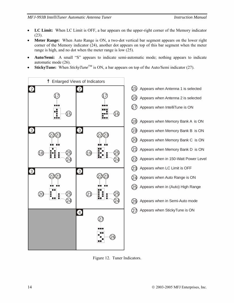
Figure 11. Main Mode Menus Display.
Tuner Indicators Various tuner indicators are shown on the main menus to indicate tuner status. Refer to Figure 11 for locations of these indicators. The number enclosed within ( ) is the item number of Figure 12.
• Antenna: A small “1” appears to indicate antenna 1 is selected (15); a small “2” appears to indicate antenna 2 is selected (16).
• IntelliTune: When IntelliTuneTM is ON, a bar appears on top of the Antenna indicator (17).
• Memory: A small “A”, “B”, “C” or “D” appears to indicator the selected memory bank when Memory is ON (18-21).
• Power Level: When 150-watt power level is selected, a bar appears on the upper-left corner of the Memory indicator (22).
MFJ-993B IntelliTuner Automatic Antenna Tuner Instruction Manual
© 2003-2005 MFJ Enterprises, Inc. 14
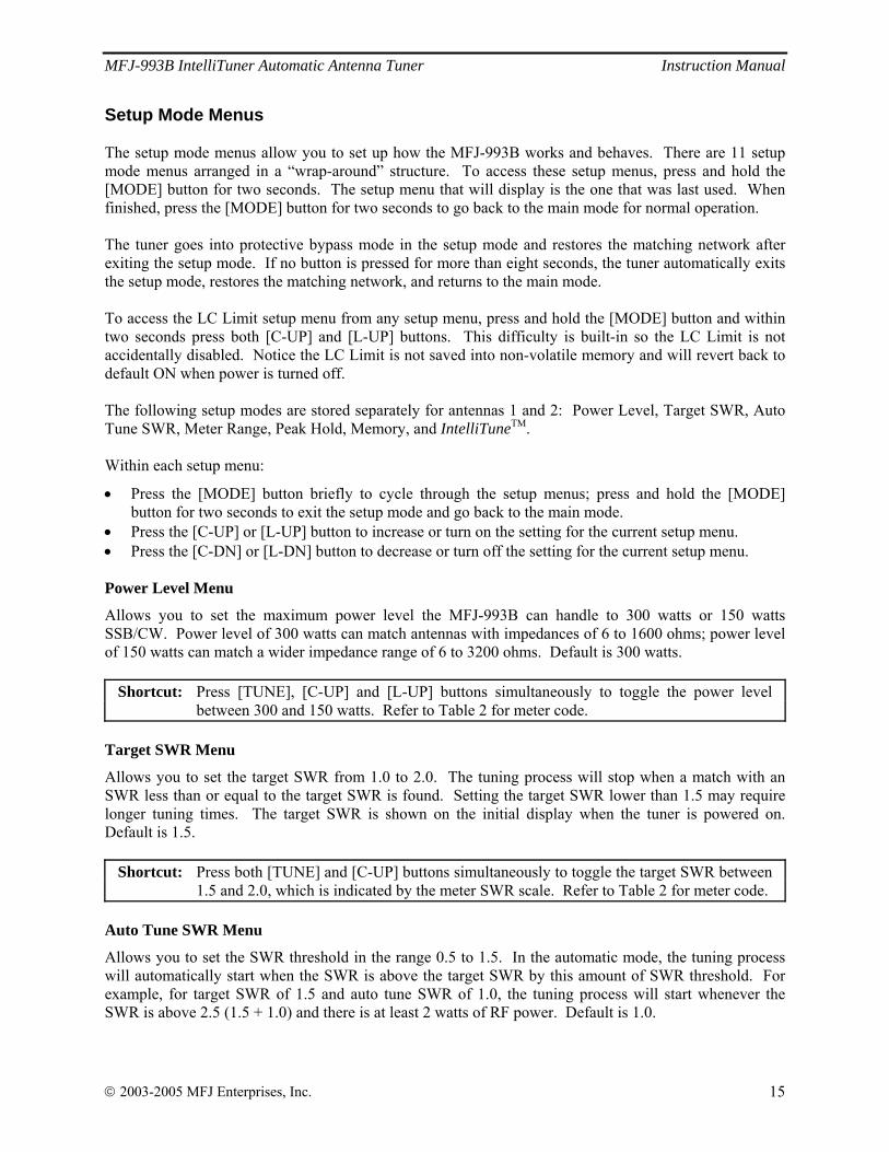
• LC Limit: When LC Limit is OFF, a bar appears on the upper-right corner of the Memory indicator (23).
• Meter Range: When Auto Range is ON, a two-dot vertical bar segment appears on the lower right corner of the Memory indicator (24), another dot appears on top of this bar segment when the meter range is high, and no dot when the meter range is low (25).
• Auto/Semi: A small “S” appears to indicate semi-automatic mode; nothing appears to indicate automatic mode (26).
• StickyTune: When StickyTuneTM is ON, a bar appears on top of the Auto/Semi indicator (27).
2 2
4
3
3 3
3
Enlarged Views of Indicators
Appears when
Appears when Antenna 2 is selected
Appears when IntelliTune is ON
Appears when Memory Bank A is ON
Appears when Memory Bank B is ON
Appears when Memory Bank C is ON
Appears when Memory Bank D is ON
Appears when in 150-Watt Power Level
Appears when LC Limit is OFF
Appears when Auto Range is ON
Appears when in (Auto) High Range
Appears when in Semi-Auto mode
Appears when StickyTune is ON
Antenna 1 is selected
16
17
18
19
20
21
15
25
22
23
24
26
27
15
17
16
17
20
22 23
2425 21
22 23
2425
18
22 23
2425 19
22 23
2425
26
27
Figure 12. Tuner Indicators.
MFJ-993B IntelliTuner Automatic Antenna Tuner Instruction Manual
© 2003-2005 MFJ Enterprises, Inc. 15
Setup Mode Menus The setup mode menus allow you to set up how the MFJ-993B works and behaves. There are 11 setup mode menus arranged in a “wrap-around” structure. To access these setup menus, press and hold the [MODE] button for two seconds. The setup menu that will display is the one that was last used. When finished, press the [MODE] button for two seconds to go back to the main mode for normal operation. The tuner goes into protective bypass mode in the setup mode and restores the matching network after exiting the setup mode. If no button is pressed for more than eight seconds, the tuner automatically exits the setup mode, restores the matching network, and returns to the main mode. To access the LC Limit setup menu from any setup menu, press and hold the [MODE] button and within two seconds press both [C-UP] and [L-UP] buttons. This difficulty is built-in so the LC Limit is not accidentally disabled. Notice the LC Limit is not saved into non-volatile memory and will revert back to default ON when power is turned off. The following setup modes are stored separately for antennas 1 and 2: Power Level, Target SWR, Auto Tune SWR, Meter Range, Peak Hold, Memory, and IntelliTuneTM. Within each setup menu:
• Press the [MODE] button briefly to cycle through the setup menus; press and hold the [MODE] button for two seconds to exit the setup mode and go back to the main mode.
• Press the [C-UP] or [L-UP] button to increase or turn on the setting for the current setup menu. • Press the [C-DN] or [L-DN] button to decrease or turn off the setting for the current setup menu. Power Level Menu
Allows you to set the maximum power level the MFJ-993B can handle to 300 watts or 150 watts SSB/CW. Power level of 300 watts can match antennas with impedances of 6 to 1600 ohms; power level of 150 watts can match a wider impedance range of 6 to 3200 ohms. Default is 300 watts.
Shortcut: Press [TUNE], [C-UP] and [L-UP] buttons simultaneously to toggle the power level between 300 and 150 watts. Refer to Table 2 for meter code.
Target SWR Menu
Allows you to set the target SWR from 1.0 to 2.0. The tuning process will stop when a match with an SWR less than or equal to the target SWR is found. Setting the target SWR lower than 1.5 may require longer tuning times. The target SWR is shown on the initial display when the tuner is powered on. Default is 1.5.
Shortcut: Press both [TUNE] and [C-UP] buttons simultaneously to toggle the target SWR between 1.5 and 2.0, which is indicated by the meter SWR scale. Refer to Table 2 for meter code.
Auto Tune SWR Menu
Allows you to set the SWR threshold in the range 0.5 to 1.5. In the automatic mode, the tuning process will automatically start when the SWR is above the target SWR by this amount of SWR threshold. For example, for target SWR of 1.5 and auto tune SWR of 1.0, the tuning process will start whenever the SWR is above 2.5 (1.5 + 1.0) and there is at least 2 watts of RF power. Default is 1.0.
MFJ-993B IntelliTuner Automatic Antenna Tuner Instruction Manual
© 2003-2005 MFJ Enterprises, Inc. 16
Shortcut: Press both [TUNE] and [L-UP] buttons simultaneously to cycle the auto tune SWR among 0.5, 1.0 and 1.5. Refer to Table 2 for meter code.
Meter Range Menu
Allows you to select the meter scale range. In the 30 watts (low) range, the forward full scale is 30 watts and the reflected full scale is 6 watts (divide the meter reading by 10). In the 300 watts (high) range, the forward full scale is 300 watts and the reflected full scale is 60 watts. Auto range automatically sets the meter scales according to the input RF power to the tuner. Forward power greater than 30 watts or reflected power greater than six watts automatically sets the meter to the high power range. Forward power less than 25 watts and reflected power less than four watts automatically set the meter to the low power range. Refer to Figures 11 and 12 for the on-screen Meter Range indicators. Default is 300 watts range.
Shortcut: Press both [TUNE] and [L-DN] buttons simultaneously to cycle the meter range among 30 watts, 300 watts and auto range. Refer to Table 2 for meter code.
Peak Hold Menu
When the peak hold function is ON, the highest activated segment of the forward bar meter remains visible for about one second, so that you can more easily read it. When OFF, the meter functions normally. Default is ON. Memory Menu
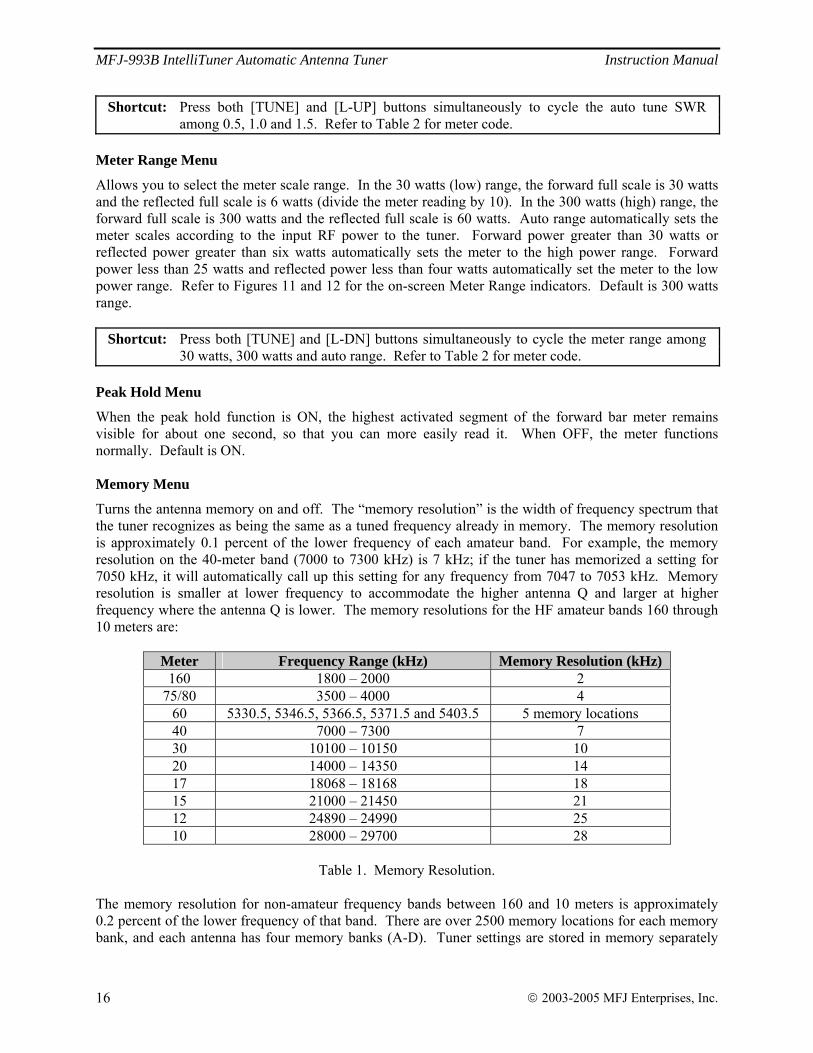
Turns the antenna memory on and off. The “memory resolution” is the width of frequency spectrum that the tuner recognizes as being the same as a tuned frequency already in memory. The memory resolution is approximately 0.1 percent of the lower frequency of each amateur band. For example, the memory resolution on the 40-meter band (7000 to 7300 kHz) is 7 kHz; if the tuner has memorized a setting for 7050 kHz, it will automatically call up this setting for any frequency from 7047 to 7053 kHz. Memory resolution is smaller at lower frequency to accommodate the higher antenna Q and larger at higher frequency where the antenna Q is lower. The memory resolutions for the HF amateur bands 160 through 10 meters are:
Meter Frequency Range (kHz) Memory Resolution (kHz) 160 1800 – 2000 2
75/80 3500 – 4000 4 60 5330.5, 5346.5, 5366.5, 5371.5 and 5403.5 5 memory locations 40 7000 – 7300 7 30 10100 – 10150 10 20 14000 – 14350 14 17 18068 – 18168 18 15 21000 – 21450 21 12 24890 – 24990 25 10 28000 – 29700 28
Table 1. Memory Resolution.
The memory resolution for non-amateur frequency bands between 160 and 10 meters is approximately 0.2 percent of the lower frequency of that band. There are over 2500 memory locations for each memory bank, and each antenna has four memory banks (A-D). Tuner settings are stored in memory separately
MFJ-993B IntelliTuner Automatic Antenna Tuner Instruction Manual
© 2003-2005 MFJ Enterprises, Inc. 17
for Antenna 1 and Antenna 2 (settings for balanced line or single-wire antenna are stored as Antenna 1). This provides memory for up to eight different antennas. Refer to Figures 11 and 12 for the on-screen Memory indicator. Defaults are memory banks 1A and 2A ON.
Shortcut: Press both [TUNE] and [C-DN] buttons simultaneously to turn on the antenna memory and to cycle the memory banks A, B, C and D. Refer to Table 2 for meter code.
To clear the memory for an antenna (all four banks), select the antenna with the [ANT] button, turn off the power to the tuner, then press and hold both [TUNE] and [C-DN] buttons while turning on the power. A DELETE ANTENNA message will appear. “Total Reset” erases both antenna memories and returns all tuner settings to their factory default states. To achieve this, turn power off, press and hold [TUNE], [L-DN] and [C-DN] buttons while turning on the power. A TOTAL RESET message will appear.
Note: Pressing [TUNE], [C-DN] and [L-DN] buttons simultaneously overwrites the tuner memory with the current tuner setting; settings with SWR greater than 3.0 will not be stored.
IntelliTune Menu
Turns the IntelliTuneTM tuning algorithm on and off. When the tuner cannot find an appropriate setting in its memory, it begins its calculation function. It measures the complex impedance of the antenna (load) at the transmitting frequency, then it calculates the L/C components needed for a match. Then it fine-tunes the component values. If for any reason the tuner cannot calculate the load impedance, it proceeds to yet another method of calculation. If for any reason, this function can be turned off. Refer to Figures 11 and 12 for the on-screen IntelliTuneTM indicator. Default is ON. SWR Beep Menu
Turns the audio SWR meter on and off. The audio meter is a series of beeps where one beep indicates SWR of 1.5 or less, two beeps indicate SWR of 1.6 to 2.0, three beeps indicate SWR of 2.1 to 2.5, and four beeps indicate SWR of 2.6 to 3.0. For SWR above 3.0, “SWR” (di-di-dit di-dah-dah di-dah-dit) will be sent on CW. This functions independent of the acknowledgement beep setting. Default is OFF.
Shortcut: Press both [L-UP] and [L-DN] buttons simultaneously to toggle SWR Beep on and off. Beep Menu
Acknowledgement beep sounds each time a parameter is changed to acknowledge it. This also controls the CW notification of “QRO”, “QRP” and “QRT”. This function can be turned OFF for silent operation, and this is independent of the SWR beep setting. Default is ON. Refresh Menu
When the refresh function is ON, the display is updated while tuning is in progress. Default is OFF.
Note: Refresh slows tuning progress as it takes time to update the display.
MFJ-993B IntelliTuner Automatic Antenna Tuner Instruction Manual
© 2003-2005 MFJ Enterprises, Inc. 18
LC Limit Menu
The upper limits of inductance (L) and capacitance (C) are factory-limited according to frequency and maximum power rating; i.e., higher frequencies need less inductance and less capacitance when the L-network is properly tuned. Pressing [C-UP] and/or [L-UP] allows capacitance and inductance to be increased only to these limits. When a selected capacitance or inductance is higher than its allowed limit, and the frequency is changed, that selection is automatically reduced to the value of its limit. These limits are used to prevent matching of extreme load impedance outside the tuner’s specification, which may result in excess voltage and/or current across the tuner’s components. This setting is not stored in non-volatile memory and reverts back to the default when the tuner power is turned off. Refer to Figures 11 and 12 for the on-screen LC Limit indicator. Default is ON.
WARNING: LC Limit is a safety precaution; the tuner is in danger of being damaged if this function is turned off.
Operation
Manual Tuning In certain cases the operator may wish to “touch up” the tuner’s settings. For example, if the target SWR is set at the default of 1.5, the tuner will stop when a match of 1.5 is found. In all cases, manual tuning gives the user control of the tuner if desired, and the L-Network menu provides a picture of the matching network configuration. Manual tuning is accomplished by using the [C-UP], [C-DN], [L-UP], and [L-DN] buttons. Since it is not known if more or less capacitance (or inductance) is needed, manual tuning must be by trial-and-error. Press [C-UP] one time, and the reflected power will indicate if [C-UP] was the right “direction.” If it was, press [C-UP] again and observe reflected power. If not, press [C-DN] twice (once to return to the original setting of C, and once for one click past it). Manual tuning of inductance is similarly accomplished, using [L-UP] and [L-DN]. Since the capacitance and inductance are interdependent, some back-and-forth between the two may be needed, just as in a conventional tuner with knobs. Once you are familiar with this process, you will learn how to match certain antennas and frequencies. Pressing [C-UP] and [C-DN] buttons simultaneously moves the capacitance back and forth from one side of the inductance to the other. The L-Network menu displays the capacitance on the left to indicate that the capacitance is on the antenna side (corresponding with the rear panel configuration of connectors); the capacitance value moves to the right side of the display when the capacitance is on the transmitter side of the inductance. A general rule of thumb is that loads with impedance higher than 50 ohms call for the capacitance on the antenna side; loads with impedance lower than 50 ohms call for the capacitance on the transmitter side. Pressing [C-DN] and [L-DN] simultaneously or pressing [TUNE] quickly places the tuner in bypass mode; i.e. zero inductance and zero capacitance. RF from the transmitter goes directly to the antenna with no matching. The reflected needle bouncing to 20-watt mark indicates changing to bypass mode. Also, the decimal point in the SWR reading is replaced with a comma. Pressing [TUNE], [C-DN] and [L-DN] simultaneously overwrites the tuner memory with the current tuner setting; settings with SWR greater than 3.0 will not be stored. Both forward and reflected needles go to full scale and one beep indicate memory overwrite.
MFJ-993B IntelliTuner Automatic Antenna Tuner Instruction Manual
© 2003-2005 MFJ Enterprises, Inc. 19
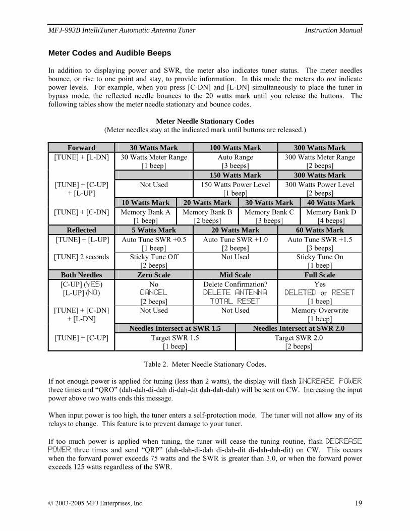
Meter Codes and Audible Beeps In addition to displaying power and SWR, the meter also indicates tuner status. The meter needles bounce, or rise to one point and stay, to provide information. In this mode the meters do not indicate power levels. For example, when you press [C-DN] and [L-DN] simultaneously to place the tuner in bypass mode, the reflected needle bounces to the 20 watts mark until you release the buttons. The following tables show the meter needle stationary and bounce codes.
Meter Needle Stationary Codes (Meter needles stay at the indicated mark until buttons are released.)
Forward 30 Watts Mark 100 Watts Mark 300 Watts Mark
[TUNE] + [L-DN] 30 Watts Meter Range [1 beep]
Auto Range [3 beeps]
300 Watts Meter Range [2 beeps]
150 Watts Mark 300 Watts Mark [TUNE] + [C-UP]
+ [L-UP] Not Used 150 Watts Power Level
[1 beep] 300 Watts Power Level
[2 beeps] 10 Watts Mark 20 Watts Mark 30 Watts Mark 40 Watts Mark
[TUNE] + [C-DN] Memory Bank A [1 beep]
Memory Bank B [2 beeps]
Memory Bank C [3 beeps]
Memory Bank D [4 beeps]
Reflected 5 Watts Mark 20 Watts Mark 60 Watts Mark [TUNE] + [L-UP] Auto Tune SWR +0.5
[1 beep] Auto Tune SWR +1.0
[2 beeps] Auto Tune SWR +1.5
[3 beeps] [TUNE] 2 seconds Sticky Tune Off
[2 beeps] Not Used
Sticky Tune On
[1 beep] Both Needles Zero Scale Mid Scale Full Scale [C-UP] (YES) [L-UP] (NO)
No CANCEL [2 beeps]
Delete Confirmation? DELETE ANTENNA TOTAL RESET
Yes DELETED or RESET
[1 beep] [TUNE] + [C-DN]
+ [L-DN] Not Used Not Used Memory Overwrite
[1 beep] Needles Intersect at SWR 1.5 Needles Intersect at SWR 2.0
[TUNE] + [C-UP] Target SWR 1.5 [1 beep]
Target SWR 2.0 [2 beeps]
Table 2. Meter Needle Stationary Codes.
If not enough power is applied for tuning (less than 2 watts), the display will flash INCREASE POWER three times and “QRO” (dah-dah-di-dah di-dah-dit dah-dah-dah) will be sent on CW. Increasing the input power above two watts ends this message. When input power is too high, the tuner enters a self-protection mode. The tuner will not allow any of its relays to change. This feature is to prevent damage to your tuner. If too much power is applied when tuning, the tuner will cease the tuning routine, flash DECREASE POWER three times and send “QRP” (dah-dah-di-dah di-dah-dit di-dah-dah-dit) on CW. This occurs when the forward power exceeds 75 watts and the SWR is greater than 3.0, or when the forward power exceeds 125 watts regardless of the SWR.
MFJ-993B IntelliTuner Automatic Antenna Tuner Instruction Manual
© 2003-2005 MFJ Enterprises, Inc. 20
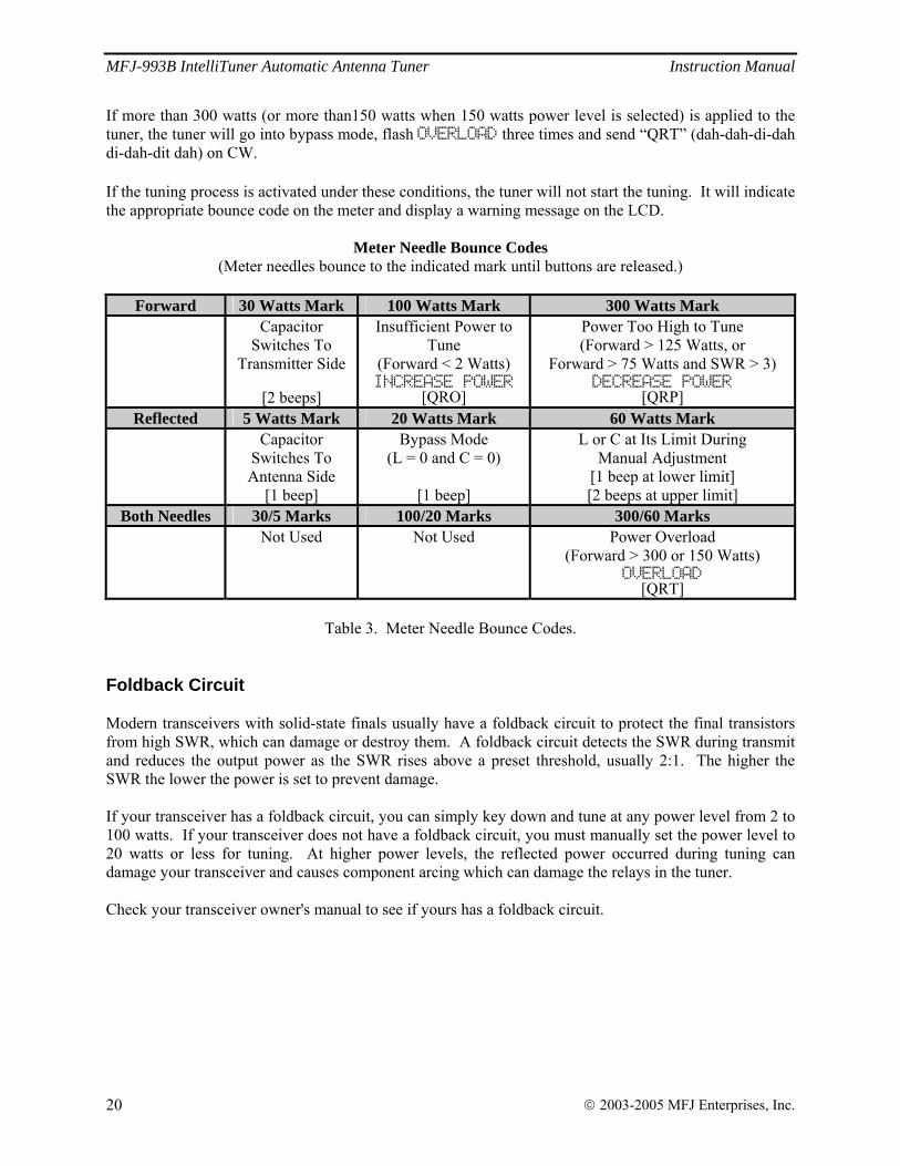
If more than 300 watts (or more than150 watts when 150 watts power level is selected) is applied to the tuner, the tuner will go into bypass mode, flash OVERLOAD three times and send “QRT” (dah-dah-di-dah di-dah-dit dah) on CW. If the tuning process is activated under these conditions, the tuner will not start the tuning. It will indicate the appropriate bounce code on the meter and display a warning message on the LCD.
Meter Needle Bounce Codes (Meter needles bounce to the indicated mark until buttons are released.)
Forward 30 Watts Mark 100 Watts Mark 300 Watts Mark
Capacitor Switches To
Transmitter Side
[2 beeps]
Insufficient Power to Tune
(Forward < 2 Watts) INCREASE POWER
[QRO]
Power Too High to Tune (Forward > 125 Watts, or
Forward > 75 Watts and SWR > 3) DECREASE POWER
[QRP] Reflected 5 Watts Mark 20 Watts Mark 60 Watts Mark
Capacitor Switches To Antenna Side
[1 beep]
Bypass Mode (L = 0 and C = 0)
[1 beep]
L or C at Its Limit During Manual Adjustment
[1 beep at lower limit] [2 beeps at upper limit]
Both Needles 30/5 Marks 100/20 Marks 300/60 Marks Not Used Not Used Power Overload
(Forward > 300 or 150 Watts) OVERLOAD
[QRT]
Table 3. Meter Needle Bounce Codes. Foldback Circuit Modern transceivers with solid-state finals usually have a foldback circuit to protect the final transistors from high SWR, which can damage or destroy them. A foldback circuit detects the SWR during transmit and reduces the output power as the SWR rises above a preset threshold, usually 2:1. The higher the SWR the lower the power is set to prevent damage. If your transceiver has a foldback circuit, you can simply key down and tune at any power level from 2 to 100 watts. If your transceiver does not have a foldback circuit, you must manually set the power level to 20 watts or less for tuning. At higher power levels, the reflected power occurred during tuning can damage your transceiver and causes component arcing which can damage the relays in the tuner. Check your transceiver owner's manual to see if yours has a foldback circuit.
MFJ-993B IntelliTuner Automatic Antenna Tuner Instruction Manual
© 2003-2005 MFJ Enterprises, Inc. 21
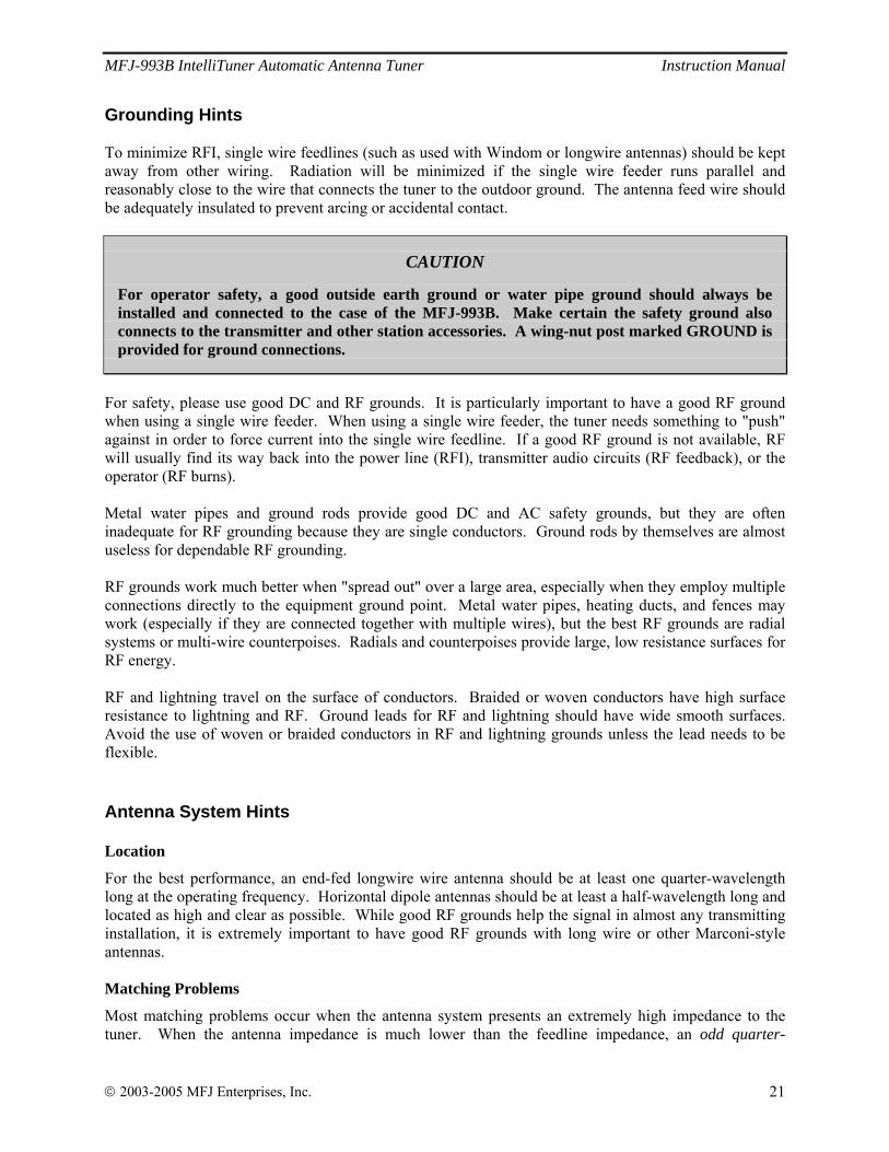
Grounding Hints To minimize RFI, single wire feedlines (such as used with Windom or longwire antennas) should be kept away from other wiring. Radiation will be minimized if the single wire feeder runs parallel and reasonably close to the wire that connects the tuner to the outdoor ground. The antenna feed wire should be adequately insulated to prevent arcing or accidental contact.
CAUTION
For operator safety, a good outside earth ground or water pipe ground should always be installed and connected to the case of the MFJ-993B. Make certain the safety ground also connects to the transmitter and other station accessories. A wing-nut post marked GROUND is provided for ground connections.
For safety, please use good DC and RF grounds. It is particularly important to have a good RF ground when using a single wire feeder. When using a single wire feeder, the tuner needs something to "push" against in order to force current into the single wire feedline. If a good RF ground is not available, RF will usually find its way back into the power line (RFI), transmitter audio circuits (RF feedback), or the operator (RF burns). Metal water pipes and ground rods provide good DC and AC safety grounds, but they are often inadequate for RF grounding because they are single conductors. Ground rods by themselves are almost useless for dependable RF grounding. RF grounds work much better when "spread out" over a large area, especially when they employ multiple connections directly to the equipment ground point. Metal water pipes, heating ducts, and fences may work (especially if they are connected together with multiple wires), but the best RF grounds are radial systems or multi-wire counterpoises. Radials and counterpoises provide large, low resistance surfaces for RF energy. RF and lightning travel on the surface of conductors. Braided or woven conductors have high surface resistance to lightning and RF. Ground leads for RF and lightning should have wide smooth surfaces. Avoid the use of woven or braided conductors in RF and lightning grounds unless the lead needs to be flexible. Antenna System Hints Location
For the best performance, an end-fed longwire wire antenna should be at least one quarter-wavelength long at the operating frequency. Horizontal dipole antennas should be at least a half-wavelength long and located as high and clear as possible. While good RF grounds help the signal in almost any transmitting installation, it is extremely important to have good RF grounds with long wire or other Marconi-style antennas. Matching Problems
Most matching problems occur when the antenna system presents an extremely high impedance to the tuner. When the antenna impedance is much lower than the feedline impedance, an odd quarter-
MFJ-993B IntelliTuner Automatic Antenna Tuner Instruction Manual
© 2003-2005 MFJ Enterprises, Inc. 22
wavelength feedline converts the low antenna impedance to a very high impedance at the tuner. A similar problem occurs if the antenna has an extremely high impedance and the transmission line is a multiple of a half-wavelength. The half-wavelength line repeats the very high antenna impedance at the tuner. Incorrect feedline and antenna lengths can make an otherwise perfect antenna system very difficult or impossible to tune. One example where this problem occurs is on 80 meters when an odd quarter-wave (60 to 70 feet) open wire line is used to feed a half-wave (100 to 140 feet) dipole. The odd quarter-wave line transforms the dipole's low impedance to over three thousand ohms at the tuner. This is because the mismatched feedline is an odd multiple of 1/4 wavelength long. The line inverts (or teeter-totters) the antenna impedance. A problem also occurs on 40 meters with this same antenna example. The feedline is now a multiple of a half-wave (60 to 70 feet) and connects to a full-wave high impedance antenna (100 to 140 feet). The half-wave line repeats the high antenna impedance at the tuner. The antenna system looks like several thousand ohms at the tuner on 40 meters. This places enormous strain on the balun and the insulation in the tuner, since voltages can reach several thousand volts. This can cause component arcing and heating. The following suggestions will reduce the difficulty in matching an antenna with a tuner:
• Never center feed a half-wave multi-band antenna with a high impedance feedline that is close to an odd multiple of a quarter-wave long.
• Never center feed a full-wave antenna with a feedline close to a multiple of a half-wave long.
• If this tuner will not "tune" a multi-band antenna, add or subtract 1/8 wave of feedline (for the band that won't tune) and try again.
• Never try to load a G5RV or center fed dipole on a band below the half-wave design frequency. If you want to operate an 80-meter antenna on 160 meters, feed either or both conductors as a longwire against the station ground.
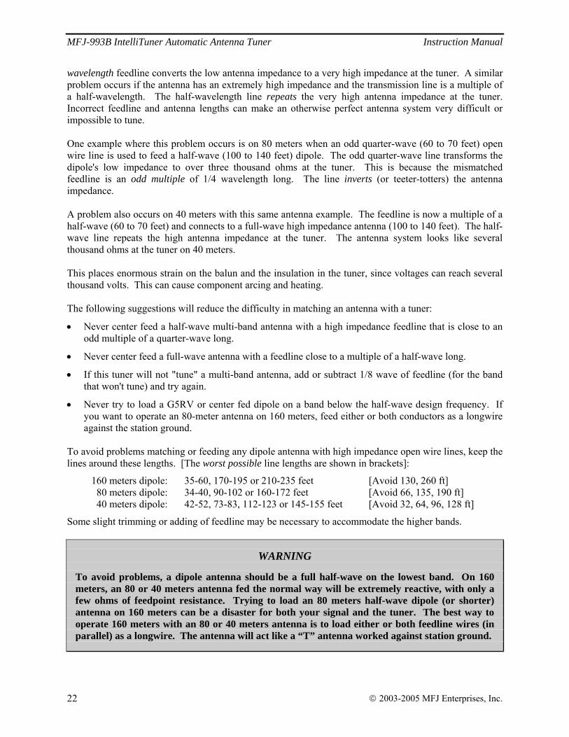
To avoid problems matching or feeding any dipole antenna with high impedance open wire lines, keep the lines around these lengths. [The worst possible line lengths are shown in brackets]:
160 meters dipole: 35-60, 170-195 or 210-235 feet [Avoid 130, 260 ft] 80 meters dipole: 34-40, 90-102 or 160-172 feet [Avoid 66, 135, 190 ft] 40 meters dipole: 42-52, 73-83, 112-123 or 145-155 feet [Avoid 32, 64, 96, 128 ft]
Some slight trimming or adding of feedline may be necessary to accommodate the higher bands.
WARNING
To avoid problems, a dipole antenna should be a full half-wave on the lowest band. On 160 meters, an 80 or 40 meters antenna fed the normal way will be extremely reactive, with only a few ohms of feedpoint resistance. Trying to load an 80 meters half-wave dipole (or shorter) antenna on 160 meters can be a disaster for both your signal and the tuner. The best way to operate 160 meters with an 80 or 40 meters antenna is to load either or both feedline wires (in parallel) as a longwire. The antenna will act like a “T” antenna worked against station ground.
MFJ-993B IntelliTuner Automatic Antenna Tuner Instruction Manual
© 2003-2005 MFJ Enterprises, Inc. 23
Appendices
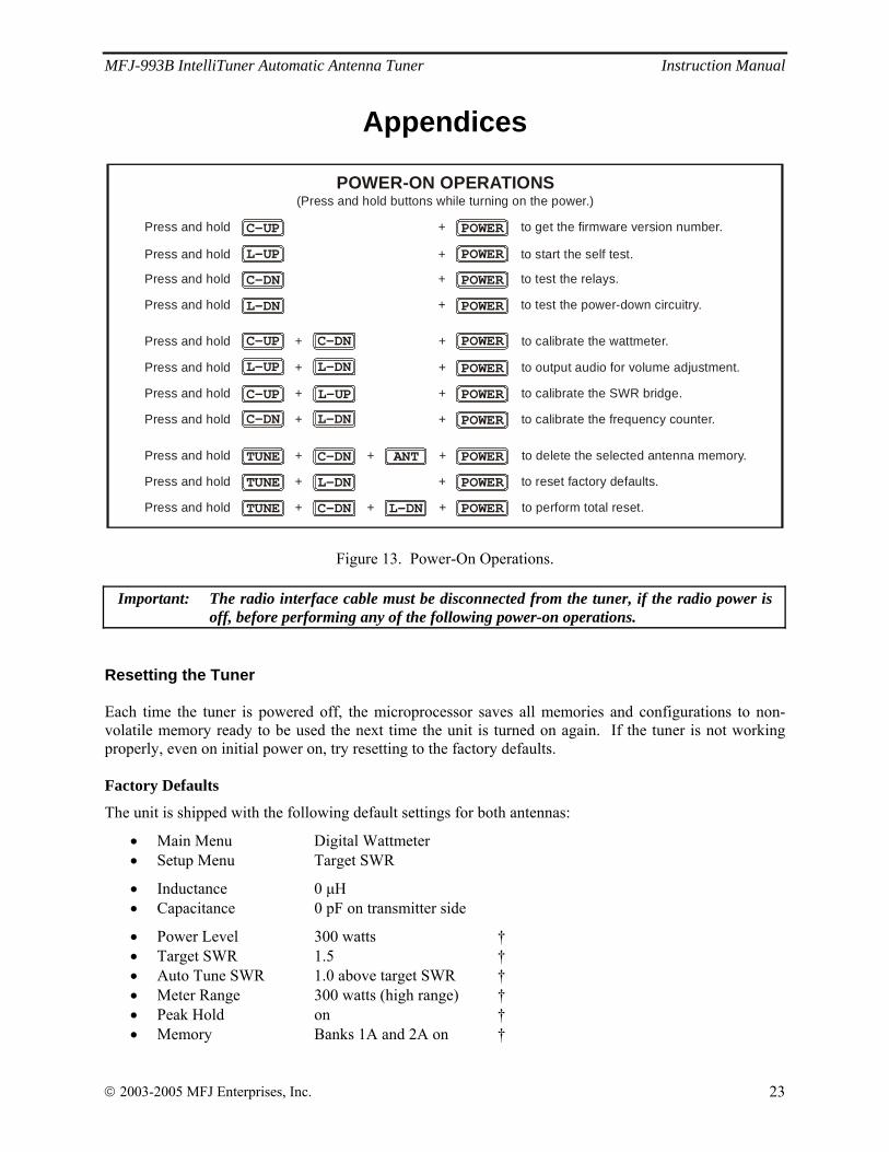
POWER-ON OPERATIONS(Press and hold buttons while turning on the power.)
Press and hold + + to calibrate the SWR bridge.
Press and hold + to start the self test.
Press and hold + + to reset factory defaults.TUNE L-DN
Press and hold + + to calibrate the wattmeter.
Press and hold + + + to delete the selected antenna memory.TUNE ANTC-DN
Press and hold + + + to perform total reset.TUNE C-DN L-DN
C-UPPress and hold + to get the firmware version number.
C-DNPress and hold + to test the relays.
L-DNL-UP
Press and hold + + to calibrate the frequency counter.
L-DNPress and hold + to test the power-down circuitry.
POWER
POWER
POWER
POWER
POWER
POWER
POWER
POWER
POWERPress and hold + + to output audio for volume adjustment.
POWER
L-UPC-UP
L-UP
C-UP C-DN
C-DN L-DN
POWER
Figure 13. Power-On Operations.
Important: The radio interface cable must be disconnected from the tuner, if the radio power is off, before performing any of the following power-on operations.
Resetting the Tuner Each time the tuner is powered off, the microprocessor saves all memories and configurations to non-volatile memory ready to be used the next time the unit is turned on again. If the tuner is not working properly, even on initial power on, try resetting to the factory defaults. Factory Defaults
The unit is shipped with the following default settings for both antennas:
• Main Menu Digital Wattmeter • Setup Menu Target SWR
• Inductance 0 μH • Capacitance 0 pF on transmitter side
• Power Level 300 watts † • Target SWR 1.5 † • Auto Tune SWR 1.0 above target SWR † • Meter Range 300 watts (high range) † • Peak Hold on † • Memory Banks 1A and 2A on †
MFJ-993B IntelliTuner Automatic Antenna Tuner Instruction Manual
© 2003-2005 MFJ Enterprises, Inc. 24
• IntelliTune on † • SWR Beep off • Beep on • Refresh off
† These settings are stored separately for antennas 1 and 2.
Note: Resetting to factory defaults does not erase the antenna memories. To reset the tuner to these defaults:
1. Turn off the power to the tuner. 2. Press and hold both the [TUNE] and [L-DN] buttons while turning the power on. 3. Release the buttons when DEFAULTS RESET appears on the display and both meter needles read
full scale. 4. Resume with normal operation. WARNING: If the MFJ-993B is behaving weirdly or acting erratic, try resetting the tuner to
factory defaults. Delete Antenna Memory
To delete an antenna memory, select Antenna 1 or Antenna 2 with the [ANT] button that you want to delete. Turn off power to the tuner, and then press and hold both the [TUNE] and [C-DN] buttons while turning the power back on. A confirmation message DELETE ANTENNA will display. Press the YES [C-UP] button to delete the antenna memory (DELETED will display and both meter needles go to full scale), or press the NO [L-UP] button to cancel (CANCEL will display and both meter needles go to zero scale). Release the button to resume normal operation. Remember that the selected antenna memory will be lost! Total Reset
To erase both antenna memories and reset to factory defaults, press and hold down the [TUNE], [C-DN] and [L-DN] buttons while turning the power on. A confirmation message TOTAL RESET will display. Press the YES [C-UP] button to delete both antenna memories and reset factory defaults (RESET will display and both meter needles go to full scale), or press the NO [L-UP] button to cancel (CANCEL will display and both meter needles go to zero scale). Release the button to resume normal operation. Remember that both antenna memories will be lost! Self Test A self-test routine will check the functions of the MFJ-993B. This routine checks the display, the meter, the front-panel buttons, the internal memory and the audio circuitry. During the self-test, you may stop the test by turning off the unit; however, this should NOT be done during the memory test or the memory could be corrupted. The self-test can be completed in approximately 30 seconds. This test can also be used to test the optional MFJ-993RC Remote Control. Make sure to press both [ANT] and [AUTO] buttons on the MFJ-993B tuner to the in position before starting the self-test, and press the buttons on the MFJ-993RC instead of the front-panel buttons when prompted.
MFJ-993B IntelliTuner Automatic Antenna Tuner Instruction Manual
© 2003-2005 MFJ Enterprises, Inc. 25
Note: Performing the self-test will reset the unit to its factory default settings.
Here is the self-test procedure:
1. Turn off the power to the tuner, and press all buttons to the out position. 2. Unplug the radio interface cable, if one is connected, from the tuner. 3. If testing the MFJ-993RC Remote Control, connect it to the Remote Port and make sure both [ANT]
and [AUTO] buttons on the tuner are pressed to the in position. 4. Set volume to a comfortable listening level. 5. Press and hold only the [L-UP] button while turning the power on. 6. The test begins by displaying a copyright message and firmware version number, such as
COPYRIGHT (c) 2003-20YY MFJ ENTERPRISES, INC. VERSION YYWW. This is the test of the display. At the same time, the forward needle of the meter also goes up slowly to full scale and then drops to zero, followed by the reflected needle going up slowly to full scale and then drops to zero. This tests the meter. Release the [L-UP] button before the message completes. To skip this copyright message, press [C-DN] button.
7. You will be prompted to press each of the front-panel buttons. The forward needle should bounce once for each press, and the reflected needle should move up a division for each press.
8. The unit then tests its non-volatile memory. Notice this step will reset the unit to its factory default settings.
9. If the unit is okay, a repetitive message PASS will be displayed and sent as Morse code (di-dah-dah-dit di-dah di-di-dit di-di-dit), and both meter needles will go to full scale. If there is a problem, a failure message will be displayed and sent; also, the forward needle will bounce and the reflected needle mark indicates the failure.
10. Once you have confirmed that the audio is okay, turn the unit off.
Failure Message
Reflected Needle (watts) Indicates
ANT FAIL 1 [ANT] button is shorted or improperly connected. MODE FAIL 2 [MODE] button is shorted or improperly connected. C-UP FAIL 3 [C-UP] button is shorted or improperly connected. C-DN FAIL 4 [C-DN] button is shorted or improperly connected. L-UP FAIL 5 [L-UP] button is shorted or improperly connected. L-DN FAIL 7.5 [L-DN] button is shorted or improperly connected. AUTO FAIL 10 [AUTO] button is shorted or improperly connected. TUNE FAIL 15 [TUNE] button is shorted or improperly connected.
Radio interface cable is connected but radio power is off. MEMORY FAIL 20 Non-volatile memory circuitry is improperly connected. WAKEUP FAIL 30 Microprocessor wakeup circuitry problem. PD FAIL 40 Power down circuitry problem.
Table 4. Failure Messages.
Power-Down Circuit Test When the 12 VDC power to the tuner is turned off, the tuner saves all settings to non-volatile memory. The Power-Down Circuit Test checks the power down detection circuitry. It is recommended that this test be done immediately after the regular self-test described above.
MFJ-993B IntelliTuner Automatic Antenna Tuner Instruction Manual
© 2003-2005 MFJ Enterprises, Inc. 26
Note: The tuner must be reset to factory defaults before performing this test. Here is the test procedure:
1. Make sure power to the tuner is off. 2. If the tuner has been reset to factory defaults, skip to step 6; otherwise continue with step 3.
3. Press and hold both the [TUNE] and [L-DN] buttons while turning the power on. 4. Release both buttons when DEFAULTS RESET appears on the display. 5. Turn the power off.
6. Press and hold only the [L-DN] button while turning the power on. 7. If the power down detection circuitry is okay, a repetitive message PASS will be displayed and sent
as Morse code (di-dah-dah-dit di-dah di-di-dit di-di-dit). If there is a problem, message PD FAIL will be displayed and sent as Morse code repetitively.
8. Turn the power off. Relay Test
WARNING: Turn off the transmitter power or disconnect the transmitter before performing this test; otherwise, damage to the tuner can result.
To test the relays and their control circuitry, press and hold the [C-DN] button while turning the power on. The message RELAY TEST will appear. Four numbers representing the relays will be shown in the center of the display. The [C-UP], [L-UP], [C-DN] and [L-DN] buttons, corresponding to the position of the relay numbers on the display, are used to toggle each relay on and off. Press button to engage the relay and release it to disengage the relay. Listen for relay clicks. Press the [TUNE] button to proceed to the next group of four relays. There are 19 relays in the tuner. Repeat the above procedure to test all the relays. Normal operation is resumed after this test. Firmware Version Number via Meter Make sure the meter is calibrated. The firmware version number is shown in the copyright message of the self-test. To obtain a decimal firmware version number via the meter, press and hold the [C-UP] button while turning the power on. The version number X.YY is represented by the meter forward needle for X (forward reading ÷ 10) and the reflected needle for YY (reflected reading). For example, forward needle on 10-watt mark and reflected needle on 20-watt mark represent firmware version number 1.20. Release button to resume normal operation. Setting the Speaker Volume To set the speaker volume, press and hold both the [L-UP] and [L-DN] buttons while turning the power on. The message SET VOLUME will display and send as Morse code repetitively. Insert a small flat blade screwdriver into the VOL hole on the front panel to adjust the volume level. Turn clockwise to increase volume level. Turn the power off.
MFJ-993B IntelliTuner Automatic Antenna Tuner Instruction Manual
© 2003-2005 MFJ Enterprises, Inc. 27
Wattmeter Calibration To calibrate the meter needles, you will need a Phillips screwdriver and a tuning tool or small flat blade screwdriver.
WARNING: Never operate the MFJ-993B with its cover removed; dangerous voltages and currents can be present during operation. Never exceed tuner specifications.
Note: The trimmers involved in this calibration are located on the circuit board behind the front
panel; do not confuse these with the SWR bridge trimmers. 1. Turn off the power to the tuner and the transmitter. 2. Remove the cover from the tuner (12 screws) with a Phillips screwdriver. 3. Press and hold both the [C-UP] and [C-DN] buttons while turning the power on. 4. A message CAL FWD METER TO 100 WATTS will display and both meter needles will bounce.
Use a small flat blade screwdriver and adjust the FWD trimpot R75, located behind the display, to set the forward needle to the 100-watt mark.
5. Press the [TUNE] button to calibrate the reflected needle. 6. A message CAL REF METER TO 20 WATTS will display. Adjust the REF trimpot R76, located
behind the display, to set the reflected needle to the 20-watt mark. 7. Press the [TUNE] button to end calibration. 8. Turn off the tuner power and secure the cover back onto the tuner. SWR Bridge Calibration To calibrate the SWR Bridge, you will need a transmitter capable of 100 watts output, a precise calibrated wattmeter, a 50-ohm dummy load, three 50-ohm SO-239 coax cables, a Phillips screwdriver, and a tuning tool or small flat blade screwdriver.
WARNING: Do not touch anything inside the tuner during operation! Serious, painful RF burns can result.
WARNING: Never operate the MFJ-993B with its cover removed; dangerous voltages and
currents can be present during operation. Never exceed tuner specifications.
Note: The trimmers involved in this calibration are located on the main circuit board in front of the TRANSMITTER connector; do not confuse these with the SWR/wattmeter trimmers.
1. Turn off the power to the tuner and the transmitter. 2. Remove the cover from the tuner (12 screws) with a Phillips screwdriver. 3. Connect the 50-ohm dummy load to the ANTENNA 1 connector; connect the wattmeter between the
transmitter and the TRANSMITTER connector on the tuner. 4. Turn on the power to the transmitter. Using a frequency in the middle of the HF band, such as 7.253
MHz, for calibration is recommended. 5. Press and hold both the [C-UP] and [L-UP] buttons while turning the tuner power on.
MFJ-993B IntelliTuner Automatic Antenna Tuner Instruction Manual
© 2003-2005 MFJ Enterprises, Inc. 28
6. A message CAL CAP AND FWD will display and both meter needles will bounce. Key the transmitter to output 100 watts and adjust trimmer capacitor C91 for minimum reflected power. Notice the reflected meter movement is exaggerated for easier calibration.
7. Key the transmitter to 100 watts output and adjust the FWD trimpot R72 until the display shows forward power of FWD=100 watts. The forward meter also should indicate 100 watts.
8. Press the [TUNE] button. A message REVERSE, CAL REF displays and the reflected meter goes to full scale.
9. Turn off the transmitter and reverse the ANTENNA 1 and TRANSMITTER connections; that is, connect the 50-ohm dummy load to the TRANSMITTER connector and connect the transmitter/wattmeter to the ANTENNA 1 connector.
10. Turn on the transmitter’s power. 11. Key the transmitter to 100 watts output and adjust the REF trimpot R71 until the display shows
reflected power of REF=100 watts. The forward meter (yes, the forward meter) also should indicate 100 watts; the reflected meter is at full scale.
12. Press the [TUNE] button to end calibration. 13. Turn off the power to the tuner and the transmitter. 14. Remove the transmitter/wattmeter and the 50-ohm dummy load from the tuner. 15. Secure the cover back onto the tuner. 16. Connect your transmitter to the TRANSMITTER connector and connect your antenna to the
appropriate antenna connector on the tuner. Frequency Counter Calibration To calibrate the frequency counter, you will need a transmitter, a 50-ohm dummy load, two 50-ohm SO-239 coax cables, a Phillips screwdriver, and a tuning tool or small flat blade screwdriver.
WARNING: Do not touch anything inside the tuner during operation! Serious, painful RF burns can result.
WARNING: Never operate the MFJ-993B with its cover removed; dangerous voltages and
currents can be present during operation. Never exceed tuner specifications. 1. Turn off the power to the tuner and the transmitter. 2. Remove the cover from the tuner (12 screws) with a Phillips screwdriver. 3. Connect the 50-ohm dummy load to the ANTENNA 1 connector; connect the transmitter to the
TRANSMITTER connector on the tuner. 4. Turn on the power to the transmitter. Set and lock the frequency to exactly 29.000 MHz. 5. Press and hold both the [C-DN] and [L-DN] buttons while turning the tuner power on. Both meter
needles will go to full scale and a message CAL FREQ 29.000 will display. 6. Key the transmitter to output about 10 watts. Adjust trimmer capacitor C118 (located between the
two big integrated circuits) until the tuner displays a frequency of 29.000 MHz and the meter needles settle at the 0 watt marks. Notice the meter movement is exaggerated for easier calibration. Nominal tolerance of the frequency counter is ±1 kHz.
7. Turn off the power to the tuner and the transmitter. 8. Secure the cover back onto the tuner.
MFJ-993B IntelliTuner Automatic Antenna Tuner Instruction Manual
© 2003-2005 MFJ Enterprises, Inc. 29
In Case of Difficulty If the LCD screen is blank, check adjustment of the contrast control. If no audio is present (with audio enabled) adjust the volume control. If the tuner acts erratic, reset the tuner to factory defaults by pressing both the [TUNE] and [L-DN] buttons while turning the power on. If the tuner fails to tune, please double check all connections and follow the tuning procedures again. Be sure you are using enough inductance (through manual adjustment) and minimum capacitance. If the tuner arcs at the rated power levels, please double check all connections and follow the tuning procedures again. Ensure you are not exceeding the tuner’s rated power handling capability. Be sure you are using the least amount of inductance and the greatest capacitance possible that still allows matching the load on the operating frequency.
Note: If the tuner arcs when operating on the 160-meter band, it may be necessary to reduce transmitter output power.
If you are still unsuccessful, but the tuner does adjust and operate when used with a dummy load or another antenna, please read “Grounding Hints” on page 21 and “Antenna System Hints” on page 21. Technical Assistance If you have any problem with this unit first check the appropriate section of this manual. If the manual does not reference your problem or your problem is not solved by reading the manual, you may call MFJ Technical Service at 662-323-0549 or the MFJ Factory at 662-323-5869. You will be best helped if you have your unit, manual and all information on your station handy so you can answer any questions the technicians may ask. You can also send questions by mail to MFJ Enterprises, Inc., 300 Industrial Park Road, Starkville, MS 39759; by facsimile (FAX) to 662-323-6551; or by email to [email protected]. Send a complete description of your problem, an explanation of exactly how you are using your unit, and a complete description of your station. Also include the firmware version number of your unit. List of Accessories • MFJ-993RC: Remote control • MFJ-1316: 12 VDC 1.5 amp power supply • MFJ-5124A: Interface cable for compatible Alinco radios • MFJ-5124I: Interface cable for compatible Icom radios • MFJ-5124K: Interface cable for compatible Kenwood radios • MFJ-5124Y: Interface cable for compatible Yaesu radios • MFJ-5409: 6 feet long RS-232 cable, female DB-9 to male DB9 connector • MFJ-5803: 3 feet long RG-58 A/U 50-ohm coax cable with a PL-259 connector on each end • MFJ-5806: 6 feet long RG-58 A/U 50-ohm coax cable with a PL-259 connector on each end • MFJ-5818: 18 feet long RG-58 A/U 50-ohm coax cable with a PL-259 connector on each end
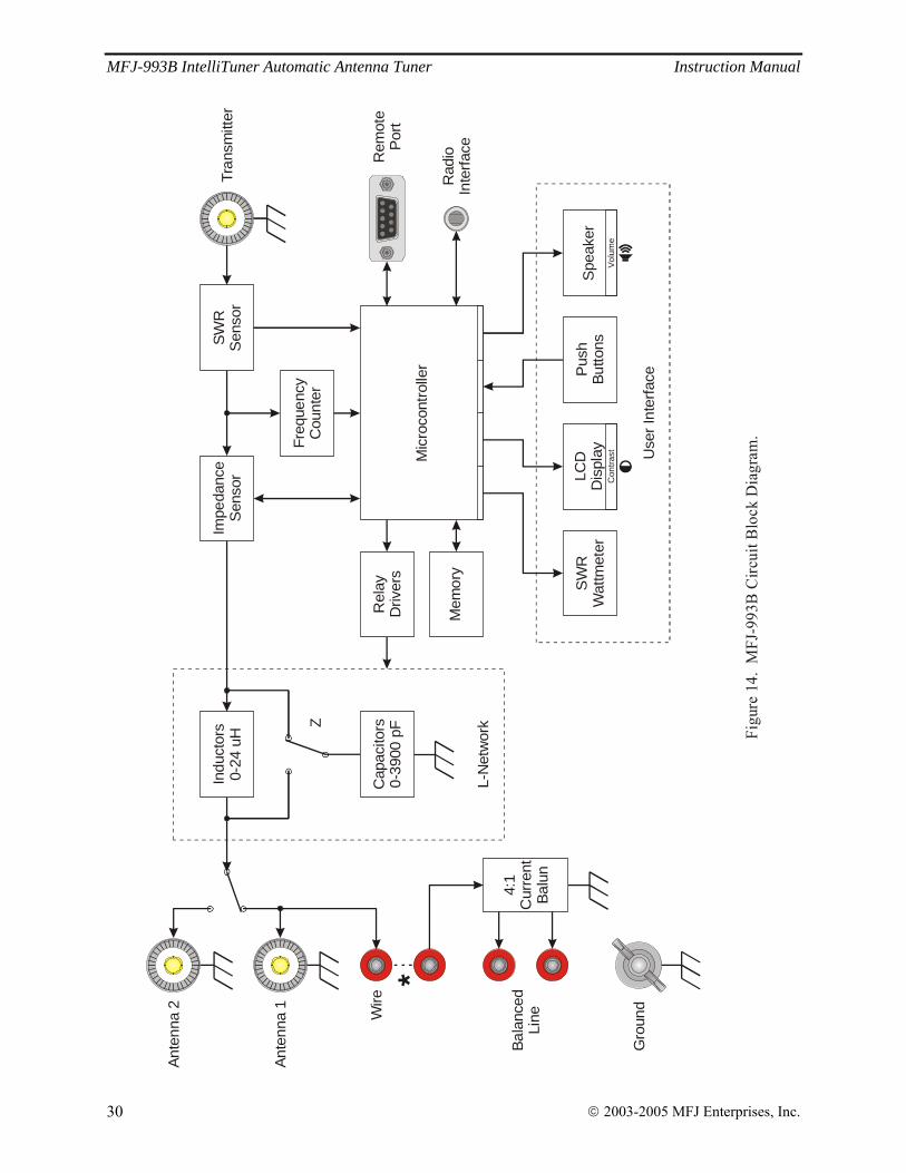
MFJ-993B IntelliTuner Automatic Antenna Tuner Instruction Manual
© 2003-2005 MFJ Enterprises, Inc. 30
Figu
re 1
4. M
FJ-9
93B
Circ
uit B
lock
Dia
gram
.
Tran
smitt
er
Ante
nna
2
Ante
nna
1
Rem
ote
Por
t
Rad
ioIn
terfa
ce
Bala
nced
LineW
ire
Impe
danc
eS
enso
rSW
RS
enso
r
Freq
uenc
yC
ount
er
Mem
ory
Mic
roco
ntro
ller
Rel
ayD
river
s
Gro
und
*
SW
RW
attm
eter
Pus
hBu
ttons
LCD
Dis
play
Spe
aker
Use
r Int
erfa
ce
Con
trast
Volu
me
4:1
Cur
rent
Balu
n
Indu
ctor
s0-
24 u
H
Cap
acito
rs0-
3900
pFZ
L-N
etw
ork

MFJ-993B IntelliTuner Automatic Antenna Tuner Instruction Manual
© 2003-2005 MFJ Enterprises, Inc. 31
Notes

MFJ-993B IntelliTuner Automatic Antenna Tuner Instruction Manual
© 2003-2005 MFJ Enterprises, Inc. 32
Notes
LIMITED 12 MONTH WARRANTY
MFJ Enterprises, Inc. warrants to the original owner of this product, if manufactured by MFJ Enterprises, Inc. and purchased from an authorized dealer or directly from MFJ Enterprises, Inc. to be free from defects in material and workmanship for a period of 12 months from date of purchase provided the following terms of this warranty are satisfied.
1. The purchaser must retain the dated proof-of-purchase (bill of sale, canceled check, credit card or money order receipt, etc.) describing the product to establish the validity of the warranty claim and submit the original or machine reproduction of such proof of purchase to MFJ Enterprises, Inc. at the time of warranty service. MFJ Enterprises, Inc. shall have the discretion to deny warranty without dated proof-of-purchase. Any evidence of alteration, erasure, or forgery shall be cause to void any and all warranty terms immediately.
2. MFJ Enterprises, Inc. agrees to repair or replace at MFJ's option without charge to the original owner any defective product under warrantee provided the product is returned postage prepaid to MFJ Enterprises, Inc. with a personal check, cashiers check, or money order for $7.00 covering postage and handling.
3. This warranty is NOT void for owners who attempt to repair defective units. Technical consultation is available by calling the Service Department at 662-323-0549 or the MFJ Factory at 662-323-5869.
4. This warranty does not apply to kits sold by or manufactured by MFJ Enterprises, Inc.
5. Wired and tested PC board products are covered by this warranty provided only the wired and tested PC board product is returned. Wired and tested PC boards installed in the owner's cabinet or connected to switches, jacks, or cables, etc. sent to MFJ Enterprises, Inc. will be returned at the owner's expense unrepaired.
6. Under no circumstances is MFJ Enterprises, Inc. liable for consequential damages to person or property by the use of any MFJ products.
7. Out-of-Warranty Service: MFJ Enterprises, Inc. will repair any out-of-warranty product provided the unit is shipped prepaid. All repaired units will be shipped COD to the owner. Repair charges will be added to the COD fee unless other arrangements are made.
8. This warranty is given in lieu of any other warranty expressed or implied.
9. MFJ Enterprises, Inc. reserves the right to make changes or improvements in design or manufacture without incurring any obligation to install such changes upon any of the products previously manufactured.
10. All MFJ products to be serviced in-warranty or out-of-warranty should be addressed to:
MFJ Enterprises, Inc., 300 Industrial Park Road Starkville, Mississippi 39759 USA
and must be accompanied by a letter describing the problem in detail along with a copy of your dated proof-of-purchase.
11. This warranty gives you specific rights, and you may also have other rights which vary from state to state.

MFJ-993B Manual
Version 1A
Printed In U.S.A. 10/2005
300 Industrial Park Road
Starkville, MS 39759
MFJ ENTERPRISES, INC.