Embed Size (px)
Citation preview

IntelliPack Series 851T
Transmitter and
Combination Transmitter/Alarm
Strain Gauge Input
USER’S MANUAL
ACROMAG INCORPORATED 30765 South Wixom Road
Wixom, MI 48393-2417 U.S.A.
Tel: (248) 624-1541
Fax: (248) 624-9234
Copyright 2001, Acromag, Inc., Printed in the USA. Data and specifications are subject to change without notice.
8500676 E

IntelliPack Series 851T Transmitter/Alarm User’s Manual Strain Gauge Input ___________________________________________________________________________________________
- 2 -
Safety Summary - Symbols on equipment:
Means “Caution, refer to this manual for additional information”.
The information contained in this manual is subject to change without notice. Acromag, Inc., makes no warranty of any kind with regard to this material, including, but not limited to, the implied warranties of merchantability and fitness for a particular purpose. Further, Acromag, Inc., assumes no responsibility for any errors that may appear in this manual and makes no commitment to update, or keep current, the information contained in this manual. No part of this manual may be copied or reproduced in any form, without the prior written consent of Acromag, Inc. Table of Contents Page 1.0 INTRODUCTION ………………………………..…….. 2
DESCRIPTION ………………………………………… 2 Key IntelliPack 851T Features……………………… 3
ACCESSORY ITEMS …………………………………. 4 IntelliPack Configuration Software ...……………… 4 IntelliPack Serial Port Adapter …………………….. 4 IntelliPack Cable………………………….………….. 4 IntelliPack Software Interface Package…..……….. 4
INTRODUCTION TO STRAIN ………………..……… 4 THE WHEATSTONE BRIDGE……………………….. 5 STRAIN GAUGE EQUATIONS………………………. 6
2.0 PREPARATION FOR USE ….……………………….. 11 UNPACKING AND INSPECTION …………………… 11 INSTALLATION ……………………………………….. 11
Jumper Installation (For Voltage Output Only)…… 11 Bridge Completion Jumper Installation.…………… 11 Remote Tare Adjustment…………………………… 12 Shunt Calibration Control Wiring…………………… 12 Mounting ……………………………………………… 12 Electrical Connections ……………………………… 12
3.0 CALIBRATION AND ADJUSTMENT……………….. 13 MODULE CALIBRATION..……………………………. 13 SENSOR CALIBRATION…..…………………………. 14 FIELD CONFIGURATION AND ADJUSTMENT……. 17 REMOTE/FIELD TARE OFFSET ADJUSTMENT….. 18 REMOTE/FIELD RESET OF LATCHED ALARMS… 19
4.0 THEORY OF OPERATION ………………………….. 19 5.0 SERVICE AND REPAIR …………………………….. 20
SERVICE AND REPAIR ASSISTANCE ……………. 20 PRELIMINARY SERVICE PROCEDURE ..…………. 20
6.0 SPECIFICATIONS ……………………………………. 20 MODEL NUMBER DEFINITION……………………… 20 INPUT SPECIFICATIONS ……………………………. 20 ANALOG OUTPUT SPECIFICATIONS……………… 22 RELAY OUTPUT SPECIFICATIONS……………….. 22 ENCLOSURE/PHYSICAL SPECIFICATIONS …….. 22 APPROVALS ………………………………………….. 22 ENVIRONMENTAL SPECIFICATIONS….………….. 23 FIELD CONFIGURATION AND CONTROLS..……... 23 HOST COMPUTER COMMUNICATION……..……… 24 SOFTWARE CONFIGURATION……..…………….… 24
List of Drawings Page Simplified Schematic (4501-884)……………………….… 29 Functional Block Diagram (4501-885)………….………… 29 Computer to IntelliPack Connections (4501-643).………. 30 Bridge Completion Connections (4501-887)…………….. 30 Electrical Connections Pg 1 of 2 (4501-886)…………….. 31 Electrical Connections Pg 2 of 2 (4501-886)…………….. 31 Interposing Relay Conn. & Contact Pro. (4501-646)……. 32 Enclosure Dimensions (4501-888) …………………..…… 32 REVISION HISTORY 33
Windows 95/98/2000/NT are registered trademarks of Microsoft
Corporation.
IMPORTANT SAFETY CONSIDERATIONS It is very important for the user to consider the possible adverse effects of power, wiring, component, sensor, or software failures in designing any type of control or monitoring system. This is especially important where economic property loss or human life is involved. It is important that the user employ satisfactory overall system design. It is agreed between the Buyer and Acromag, that this is the Buyer's responsibility.
1.0 INTRODUCTION
Series 851T Strain Gauge Transmitters and combination
Transmitter/Alarms are the newest members of the popular
Acromag IntelliPack Transmitter and Alarm Family. These
instructions cover the hardware functionality of the IntelliPack
models listed in Table 1. Supplementary sheets are attached for
units with special options or features. Table 1: Models Covered in This Manual
Series/ Input Type
-Options/Output/ Enclosure/Approvals1
-Factory Configuration2
851T -05003 -C
851T -15003 -C
Notes (Table 1): 1. Agency approvals for cULus Listed. 2. Include the “-C” suffix to specify factory configuration option.
Otherwise, no suffix is required for standard configuration. 3. Model 851T-0500 units have transmitter functionality only,
while 851T-1500 transmitters include an alarm relay.
Module programming, transmitter operation, and the
IntelliPack Configuration Software is also covered in the
IntelliPack Transmitter Configuration Manual (8500-570).
DESCRIPTION
Strain gauges are widely employed in sensors that detect
force and force-related parameters, such as torque, acceleration,
pressure, and vibration. Strain sensors undergo a small
mechanical deformation with an applied force that results in a
small change in resistance proportional to the applied force.
They are commonly wired using the Wheatstone bridge, whose
resultant output voltage is directly related to the resistance in
each leg of the bridge and the bridge excitation voltage.
These models provide a single ratiometric input for interface
to strain gauge sensors wired in Wheatstone bridge format, or to
6-wire load cells. The output of this transmitter is an isolated
process current or voltage proportional to the measured strain.
Optionally, the output includes an isolated, Single-Pole Double-
Throw (SPDT) electro-mechanical alarm relay (Model 851T-
1500). The module also includes an adjustable regulated bridge
excitation supply. Remote sensing provides lead-wire
compensation and will boost this voltage level as necessary so
that the programmed excitation is applied at the remote sensor.
The differential input conversion is ratiometric, making input
measurements immune to changes in the excitation voltage.
Sensor lead break detection is also provided. Provisions for half
and quarter bridge completion are built-in. An isolated digital
input is included for remotely triggering a tare conversion, or to
optionally reset a latched alarm relay. Units are reconfigured,
calibrated, and interrogated via our easy to use Windows
95/98/2000 or NT IntelliPack Configuration Program.
!

IntelliPack Series 851T Transmitter/Alarm User's Manual Strain Gauge Input
___________________________________________________________________________________________
- 3 -
In-field reconfigurability of transmitter zero and full-scale, plus
alarm level and deadband (851T-1500 models), is also possible
with front-panel push-buttons and status LED’s. Front-panel
push buttons can also be used to reset a latched alarm. The
alarm relay has a yellow LED on the front of the module that
provides a visual indication of the high or low alarm condition.
Additionally, green “Run”, yellow “Status”, and “Zero/Full-Scale”
LED’s provide local feedback of operating mode, system
diagnostics, and field configuration status. All IntelliPack
modules contain an advanced technology microcontroller with
integrated downloadable flash memory for non-volatile program,
configuration, calibration, and parameter data storage. Once
configured, these modules may operate independent of the host
computer for true embedded monitoring and control.
The module uses a high resolution, low noise, Sigma-Delta,
Analog to Digital Converter (- ADC) to accurately convert the
input signal into a digitized value. An optically isolated Digital-to-
Analog Converter (DAC) provides the corresponding process
current or voltage output. A separate alarm circuit controls the
relay contacts. The input-to-output transfer function of this
transmitter may optionally be configured via a built-in linearizer
function (up to 24-segments). The module also includes an input
averaging function. The output of this transmitter may produce a
normal (ascending), or reverse (descending) response. Model
851T-1500 units include an alarm relay that may be configured as
a limit alarm with deadband applied, and with latching or non-
latching contacts, in failsafe or non-failsafe modes. A
programmed relay time delay may be implemented to help filter
transients and minimize nuisance alarms.
Units are DIN-rail mounted and removable terminal blocks
facilitate ease of installation and replacement, without having to
remove wiring. Transmitter power, output, and relay wiring are
inserted at one side of the unit, while input wiring is inserted at
the other side. Plug-in connectors are an industry standard
screw clamp type that accept a wide range of wire sizes.
All IntelliPack modules are designed to withstand harsh
industrial environments. They feature RFI, EMI, ESD, EFT, and
surge protection, plus low temperature drift, wide ambient
temperature operation, and isolation between input, power,
output, and relay contacts. They also have low radiated
emissions per CE requirements. As a wide-range DC-powered
device, the unit may be powered from DC power networks
incorporating battery backup. Since the input power is diode-
coupled, this offers reverse polarity protection and permits the
unit to be connected to redundant power supplies. It also allows
several units to safely share a single DC supply.
Flexible transmitter functionality, convenient reconfiguration,
plus an optional alarm, all combine in a single package to make
this instrument extremely powerful and useful over a broad range
of applications. The safe, compact, rugged, reconfigurable, and
reliable design of this transmitter makes it an ideal choice for
control room and field applications. Custom IntelliPack
configurations are also possible (please consult the factory).
Key IntelliPack 851T Features
• Agency Approvals - cULus Listed.
• Easy Windows Configuration - Fully reconfigurable via
our user-friendly Windows 95/98/2000 or NT IntelliPack
Configuration Program.
Key IntelliPack 851T Features…continued
• Fully Isolated – The analog input, digital input, power,
output, and relay contacts are all isolated from each other
for safety and increased noise immunity.
• Self-Diagnostics - Built-in routines operate upon power-up
for reliable service, easy maintenance, and troubleshooting.
• Nonvolatile Reprogrammable Memory - An advanced
technology microcontroller with integrated, non-volatile,
downloadable flash memory allows the functionality of this
device to be reliably reprogrammed thousands of times.
• Convenient Field Reprogrammability - This unit allows
transmitter zero and span calibration, plus alarm setpoint
and deadband adjustments, to be made via module push-
buttons and LED’s, thus facilitating in-field changes without
having to connect a host computer. Field adjustment of tare
offset is also possible via the digital input TRIG.
• Wide-Range Strain Gauge & Bridge Inputs – Can be
configured for bridge or strain gauge applications from
1mV/V to 10mV/V.
• True Ratiometric Input Conversion – The A/D reference is
generated from the excitation voltage and is simultaneous
with the input sample, optimizing resolution and increasing
accuracy. This also makes the input measurement relatively
immune to errors that result from changes in excitation level.
• Digitally Adjustable Bridge Excitation – Constant voltage
can be set from 4V to 11V, is non-volatile, and has up to
120mA of drive capability. The internal excitation can also
be turned OFF for use with external bridge excitation.
• Remote Sense - Boosts the excitation voltage at the bridge
to prevent lead-wire resistance from negatively affecting
transducer span or sensitivity. Programmed level is
continuously closed-loop monitored.
• Automatic Null-Compensation – Initial (unstrained) bridge
offset voltages can be removed via software control.
• Automatic Tare Removal – Tare weight may be removed
via software control or digital input trigger. Tare offsets may
also be manually written, without having to apply a load.
• Digital Input Provides Remote Tare or Alarm Reset – An
optically isolated digital input is provided to remotely trigger
a tare conversion, or optionally reset a latched alarm relay.
These functions can also be accomplished via software
push-buttons, and resetting a latched alarm relay can be
accomplished via the module’s front panel push-buttons.
• Bridge Completion – Module has built-in, precision ratio-
matched, half-bridge resistors and jumper terminals to
accomplish half-to-full, and quarter-to-full bridge completion.
The polarity of the bridge output may be varied by taking the
bridge completion resistors to IN+ or IN-.
• 24-Segment Linearizer – Optionally, the I/O transfer
function may be configured via a 24 segment linearizer.
Averaging may also be applied to the linearizer function.
• Universal Analog Output - Supports process current output
ranges of 0-20mA, 4-20mA, and 0-1mA, and 0-5V or 0-10V
outputs. Current outputs drive up to 550, typical. Voltage
outputs include short-circuit protection.
• Normal Or Reverse Acting Output Direction - The analog
output of this transmitter may be software configured for a
normal (ascending), or reverse (descending) response.
• Wide-Range DC-Powered – Unit is powered via a 12-36V
DC supply and the power terminal is series diode-coupled,
providing reverse polarity protection. This also makes this
transmitter compatible with systems that use redundant
supplies and/or battery back-up.

IntelliPack Series 851T Transmitter/Alarm User's Manual Strain Gauge Input
___________________________________________________________________________________________
- 4 -
Key IntelliPack 851T Features…continued
• Wide Ambient Operation - The unit is designed for reliable
operation over a wide ambient temperature range.
• Hardened For Harsh Environments - The unit will operate
reliably in harsh industrial environments and includes
protection from RFI, EMI, ESD, EFT, and surges, plus low
radiated emissions per CE requirements.
• Convenient Mounting, Removal, & Replacement - The
DIN-rail mount and plug-in type terminal blocks make
module removal and replacement easy.
• High-Resolution Precise A/D Conversion - Transmitters
include a high-resolution, low noise, Sigma-Delta Analog to
Digital Converter (- ADC) for high accuracy and reliability.
• High-Resolution Precise D/A Conversion – Output is
driven via a high-resolution, low noise, Sigma-Delta Digital-
to-Analog Converter (- DAC) for high accuracy &
reliability.
• LED Indicators - A green LED indicates power. A yellow
status LED will turn on if input signal is out of the calibrated
range. A yellow alarm LED indicates when a relay is in
alarm. These LED’s also have other functions in field
program mode. A zero/full-scale LED is used to calibrate
transmitter zero and full-scale values.
• Automatic Self-Calibration - Self-calibration is built-in to
correct for errors due to temperature drift. Additional Features Of Model 851T-1500 w/Alarm Option
• Alarm Functionality (“-1500” Units Only) - May be
programmed for limit alarms with deadband, latching/non-
latching contacts, and failsafe/non-failsafe operation.
• Digital Input Provides Wired-Reset for Latched Alarms –
This module contains a digital input channel that can be
used to remotely reset a latched alarm relay.
• High-Power SPDT Relay Contacts - Includes a Single-
Pole-Double-Throw (SPDT) electromechanical alarm relay
for switching voltages to 230VAC at currents up to 5A.
• Failsafe or Non-Failsafe Relay Operation - May be
configured for failsafe or non-failsafe relay operation.
• Configurable Setpoint With Deadband - Includes
programmable deadband to help eliminate relay “chatter”
and prolong contact life.
• Configurable Latching or Momentary Alarms - May be
configured with an automatic alarm reset, or a latching alarm
with manual push-button or software reset.
• Configurable Relay Time Delay Filters Transients -
Useful for increased noise immunity and to filter transients.
ACCESSORY ITEMS
The following IntelliPack accessories are available from
Acromag. Acromag also offers other standard and custom
transmitter and alarm types to serve a wide range of applications
(please consult the factory).
IntelliPack Configuration Software (Model 5030-881)
IntelliPack alarms and transmitters are configured with this
user-friendly Windows 95/98/200 or NT Configuration Program.
This software package includes the IntelliPack Alarm
Configuration Manual (8500-563) and IntelliPack Transmitter
Configuration Manual (8500-570).
These manuals describe software operation and various alarm
and transmitter functions in detail. The Configuration Software
also includes an on-line help function. All transmitter and alarm
functions are programmable and downloadable to the modules
via this software. Non-volatile memory provides program,
configuration, and data storage within the IntelliPack.
IntelliPack Serial Port Adapter (Model 5030-913)
This adapter serves as an isolated interface converter
between the EIA232 serial port of the host computer and the
Serial Peripheral Interface (SPI) port of the IntelliPack module. It
is used in conjunction with the Acromag IntelliPack Configuration
Software to program and configure the modules. This adapter
requires no user adjustment, no external power, and operates
transparent to the user. It receives its power from the IntelliPack
module. The adapter has a DB9S connector that mates to the
common DB9P serial port connector of a host computer. The
adapter also has a 6-wire RJ11 phone jack to connect to the
IntelliPack alarm module via a separate interconnecting cable
(described below). Refer to Drawing 4501-635 for computer to
IntelliPack connection details.
IntelliPack Cable (Model 5030-902)
This 6-wire cable is used to connect the SPI port of the
IntelliPack Serial Port Adapter to the IntelliPack. This cable
carries the SPI data and clock signals, reset signal, and +5V
power and ground signals. The cable is 6 feet long and has a 6-
wire RJ11 plug at both ends which snap into jacks on the Serial
Port Adapter and the IntelliPack module.
IntelliPack Software Interface Package (Model 800C-SIP)
The IntelliPack Software Interface Package combines the
Configuration Software (5030-881), Alarm Configuration Manual
(8500-563), Transmitter Configuration Manual (8500-570), Serial
Port Adapter (5030-913), and Cable (5030-902), into a complete
kit for interfacing with IntelliPack Alarms and Transmitters.
INTRODUCTION TO STRAIN
Because the concept of strain and its measurement &
application are complex subjects, the following information has
been included to help you gain a better understanding of this
module and its operation. If you are already familiar with strain
concepts and their application, then you may skip this section
and proceed to Section 2.0 (PREPARATION FOR USE).
Strain sensors are used to measure stress forces that result
from loading, torque, pressure, acceleration, and vibration.
These devices are commonly arranged in Wheatstone bridge
fashion. The output voltage of the strain gauge bridge is directly
proportional to the applied excitation, and any resistance
imbalance in the arms of the bridge. The output of the bridge is
normally specified in terms of millivolts of output voltage per volt
of applied excitation (mV/V), and this is usually referred to as its
rated output or sensitivity. The actual maximum or full-scale
output of a strain gauge bridge at its full-rated load is the product
of a bridge’s sensitivity (mV/V) and the applied excitation voltage.
This is referred to as the output span under full rated load.
IntelliPack Series 851T Transmitter/Alarm User's Manual Strain Gauge Input
___________________________________________________________________________________________
- 5 -
Strain is a measure of the deformation of a body when
subject to an applied force. Specifically, strain () is the
fractional change in dimension (length, width, or height) of a body
when subject to a force along that dimension. That is:
= L / L. Note that strain can be either positive (tensile), or
negative (compressive). Further, the magnitude of a strain
measurement is typically very small and is often expressed as a
whole number multiple of 10-6, or microstrain (). In most
cases, strain measurements are rarely encountered larger than a
few millistrain ( * 10-3), or about 3000.
When a body of material is subject to a force in one direction,
a phenomenon referred to as Poisson’s Strain causes the
material to contract slightly in the transverse or perpendicular
dimension. The magnitude of this contraction is a property of the
material indicated by its Poisson’s Ratio. The Poisson’s Ratio ()
is the negative ratio of the coincident compressive strain that
occurs in the transverse direction (perpendicular to the applied
force), to the strain in the axial direction (parallel to the applied
force). That is: Poisson’s Ratio () = -T / . Likewise, the
Poisson’s Strain (T)= -.
Strain gauges are devices that change resistance slightly in
response to an applied strain. These devices typically consist of
a very fine foil grid (or wire grid) that is bonded to a surface in the
direction of the applied force. The cross-sectional area of this
device is minimized to reduce the negative effect of the shear or
Poisson’s Strain. These devices are commonly referred to as
bonded-metallic or bonded-resistance strain gauges. The foil grid
is bonded to a thin backing material or carrier which is directly
attached to the test body. As a result, the strain experienced by
the test body is transferred directly to the foil grid of the strain
gauge, which responds with a linear change (or nearly linear
change) in electrical resistance. As you can surmise, properly
mounting a strain gauge is critical to its performance in ensuring
that the applied strain of a material is accurately transferred
through the adhesive and backing material, to the foil itself. Most
strain gauges have nominal resistance values that vary from 30
to 3000, with 120, 350, and 1000 being the most common.
The relationship between the resultant fractional change of
gauge resistance to the applied strain (fractional change of
length) is called the Gauge Factor (GF), or sensitivity to strain.
Specifically, the Gauge Factor is the ratio of the fractional change
in resistance to the strain: GF = (R / R) / (L / L) = (R / R) / The Gauge Factor for metallic strain gauges is typically
around 2.0. However, it is important to note that this ratio will
vary slightly in most applications and a method of accounting for
the effective Gauge Factor of a strain measurement system must
be provided (see Instrument Gauge Factor).
In the ideal sense, the resistance of a strain gauge should
change only in response to the applied strain. Unfortunately, the
strain gauge material, as well as the test material it is applied to,
will expand or contract in response to changes in temperature.
Strain gauge manufacturers attempt to minimize gauge sensitivity
to temperature by design, selecting specific strain gauge
materials for specific application materials. Though minimized,
the equivalent strain error due to the temperature coefficient of a
material is still considerable and additional temperature
compensation is usually required.
THE WHEATSTONE BRIDGE
Because strain measurement requires the detection of very
small mechanical deformations, and small resistance changes,
the resultant magnitude of most strain measurements in stress
analysis applications is commonly between 2000 and 10000, and rarely larger than about 3000. As such, an accurate
method of measuring very small changes in resistance is
required. Likewise, this method should also compensate for the
strain gauge’s inherent sensitivity to temperature. This is where
the Wheatstone Bridge comes into play.
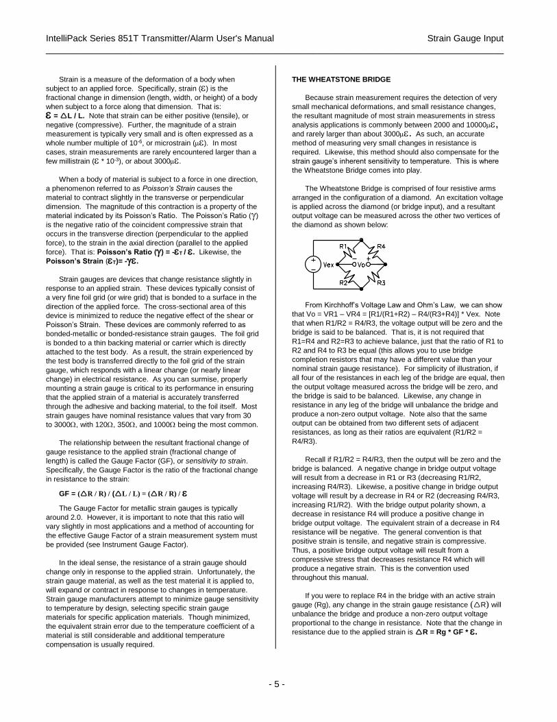
The Wheatstone Bridge is comprised of four resistive arms
arranged in the configuration of a diamond. An excitation voltage
is applied across the diamond (or bridge input), and a resultant
output voltage can be measured across the other two vertices of
the diamond as shown below:
From Kirchhoff’s Voltage Law and Ohm’s Law, we can show
that Vo = VR1 – VR4 = [R1/(R1+R2) – R4/(R3+R4)] * Vex. Note
that when R1/R2 = R4/R3, the voltage output will be zero and the
bridge is said to be balanced. That is, it is not required that
R1=R4 and R2=R3 to achieve balance, just that the ratio of R1 to
R2 and R4 to R3 be equal (this allows you to use bridge
completion resistors that may have a different value than your
nominal strain gauge resistance). For simplicity of illustration, if
all four of the resistances in each leg of the bridge are equal, then
the output voltage measured across the bridge will be zero, and
the bridge is said to be balanced. Likewise, any change in
resistance in any leg of the bridge will unbalance the bridge and
produce a non-zero output voltage. Note also that the same
output can be obtained from two different sets of adjacent
resistances, as long as their ratios are equivalent (R1/R2 =
R4/R3).
Recall if R1/R2 = R4/R3, then the output will be zero and the
bridge is balanced. A negative change in bridge output voltage
will result from a decrease in R1 or R3 (decreasing R1/R2,
increasing R4/R3). Likewise, a positive change in bridge output
voltage will result by a decrease in R4 or R2 (decreasing R4/R3,
increasing R1/R2). With the bridge output polarity shown, a
decrease in resistance R4 will produce a positive change in
bridge output voltage. The equivalent strain of a decrease in R4
resistance will be negative. The general convention is that
positive strain is tensile, and negative strain is compressive.
Thus, a positive bridge output voltage will result from a
compressive stress that decreases resistance R4 which will
produce a negative strain. This is the convention used
throughout this manual.
If you were to replace R4 in the bridge with an active strain
gauge (Rg), any change in the strain gauge resistance (R) will
unbalance the bridge and produce a non-zero output voltage
proportional to the change in resistance. Note that the change in
resistance due to the applied strain is R = Rg * GF * .
IntelliPack Series 851T Transmitter/Alarm User's Manual Strain Gauge Input
___________________________________________________________________________________________
- 6 -
If R1=R2, and R3=Rg, then substituting Rg+R for R4 in our
earlier equation for Vo yields the expression: Vo/Vex = - GF * / 4 * [1 / (1 + GF* / 2)], which is the sensitivity of this quarter-
bridge circuit. The presence of the 1/(1+GF*/2) term in the this
expression is representative of the small non-linearity of the
quarter bridge output with respect to strain. However, the effect
of this non-linearity is generally small and can be ignored for
quarter-bridge strain levels below about 5000 microstrain.
Note that the active strain gauge (Rg) may occupy one leg of
a Wheatstone Bridge (Quarter-Bridge Configuration), two legs of
a bridge (Half-Bridge Configuration), or four legs of a bridge (Full-
Bridge Configuration), with any remaining legs of the bridge
occupied by fixed resistors or "dummy" gauges. In any case, the
number of active gauges in a bridge is key to determining
whether a bridge is a quarter, half, or full bridge type.
Recall that for the bridge circuit above and the polarities set
as shown, tensile (positive) strains will produce a positive output
voltage if located in cells 1 and 3, and a negative output voltage if
located in cells 4 and 2. Compressive (negative) strains will
produce a negative output if located in cells 1 and 3, and a
positive output if located in cells 4 and 2. Changes of resistance
in adjacent arms of the bridge are subtractive if of the same sign
and they tend to cancel each other out. If the adjacent cell
resistance changes are of opposite sign, they are additive.
Likewise, resistance changes in opposite cells are additive if of
the same sign, and tend to cancel each other out if of the
opposite sign.
Because changes in resistance at adjacent bridge resistors
have the same (numerically additive) effect on the bridge output
when those changes are of the opposite sign, and have the
opposite effect (numerically subtractive) when changes in
adjacent arms are of the same sign, then by placing similar
gauges and lead-wires in adjacent arms and exposing them to
the same temperature, they act together to nullify their individual
thermal effects on the bridge output, effectively canceling the
temperature induced strain error.
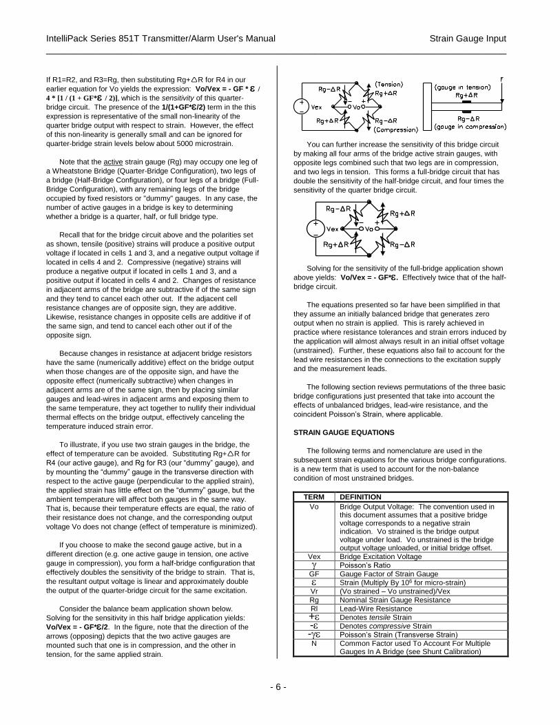
To illustrate, if you use two strain gauges in the bridge, the
effect of temperature can be avoided. Substituting Rg+R for
R4 (our active gauge), and Rg for R3 (our “dummy” gauge), and
by mounting the “dummy” gauge in the transverse direction with
respect to the active gauge (perpendicular to the applied strain),
the applied strain has little effect on the “dummy” gauge, but the
ambient temperature will affect both gauges in the same way.
That is, because their temperature effects are equal, the ratio of
their resistance does not change, and the corresponding output
voltage Vo does not change (effect of temperature is minimized).
If you choose to make the second gauge active, but in a
different direction (e.g. one active gauge in tension, one active
gauge in compression), you form a half-bridge configuration that
effectively doubles the sensitivity of the bridge to strain. That is,
the resultant output voltage is linear and approximately double
the output of the quarter-bridge circuit for the same excitation.
Consider the balance beam application shown below.
Solving for the sensitivity in this half bridge application yields:
Vo/Vex = - GF*/2. In the figure, note that the direction of the
arrows (opposing) depicts that the two active gauges are
mounted such that one is in compression, and the other in
tension, for the same applied strain.
You can further increase the sensitivity of this bridge circuit
by making all four arms of the bridge active strain gauges, with
opposite legs combined such that two legs are in compression,
and two legs in tension. This forms a full-bridge circuit that has
double the sensitivity of the half-bridge circuit, and four times the
sensitivity of the quarter bridge circuit.
Solving for the sensitivity of the full-bridge application shown
above yields: Vo/Vex = - GF*. Effectively twice that of the half-
bridge circuit.
The equations presented so far have been simplified in that
they assume an initially balanced bridge that generates zero
output when no strain is applied. This is rarely achieved in
practice where resistance tolerances and strain errors induced by
the application will almost always result in an initial offset voltage
(unstrained). Further, these equations also fail to account for the
lead wire resistances in the connections to the excitation supply
and the measurement leads.
The following section reviews permutations of the three basic
bridge configurations just presented that take into account the
effects of unbalanced bridges, lead-wire resistance, and the
coincident Poisson’s Strain, where applicable.
STRAIN GAUGE EQUATIONS
The following terms and nomenclature are used in the
subsequent strain equations for the various bridge configurations.
is a new term that is used to account for the non-balance
condition of most unstrained bridges.
TERM DEFINITION
Vo Bridge Output Voltage: The convention used in this document assumes that a positive bridge voltage corresponds to a negative strain indication. Vo strained is the bridge output voltage under load. Vo unstrained is the bridge output voltage unloaded, or initial bridge offset.
Vex Bridge Excitation Voltage
Poisson’s Ratio
GF Gauge Factor of Strain Gauge
Strain (Multiply By 106 for micro-strain)
Vr (Vo strained – Vo unstrained)/Vex
Rg Nominal Strain Gauge Resistance
Rl Lead-Wire Resistance
+ Denotes tensile Strain
- Denotes compressive Strain
- Poisson’s Strain (Transverse Strain)
N Common Factor used To Account For Multiple Gauges In A Bridge (see Shunt Calibration)
IntelliPack Series 851T Transmitter/Alarm User's Manual Strain Gauge Input
___________________________________________________________________________________________
- 7 -
In the examples presented in this manual for the polarities
given, it is assumed that a positive strain is tensile and
accompanied by a negative bridge output voltage. A negative
strain is compressive and accompanied by a positive bridge
output voltage. You can reverse this convention by removing the
negative sign from the formulas provided and flipping the polarity
of the bridge output voltage. Likewise, the internal bridge
completion resistors may be taken to either IN- or IN+.
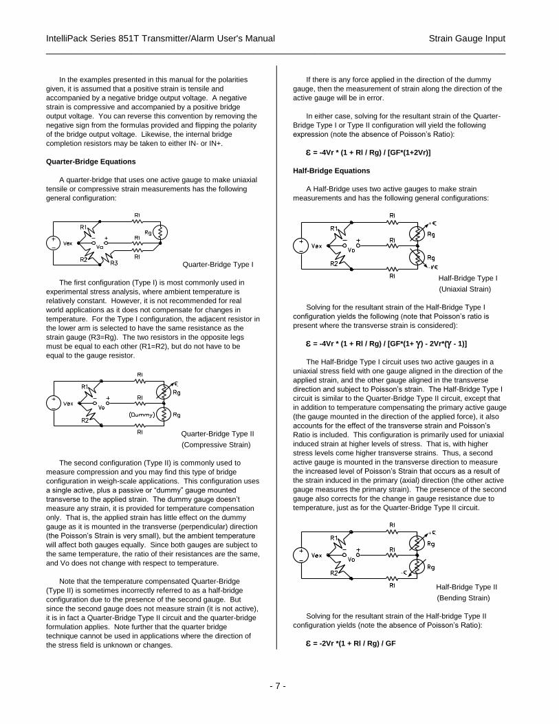
Quarter-Bridge Equations
A quarter-bridge that uses one active gauge to make uniaxial
tensile or compressive strain measurements has the following
general configuration:
Quarter-Bridge Type I
The first configuration (Type I) is most commonly used in
experimental stress analysis, where ambient temperature is
relatively constant. However, it is not recommended for real
world applications as it does not compensate for changes in
temperature. For the Type I configuration, the adjacent resistor in
the lower arm is selected to have the same resistance as the
strain gauge (R3=Rg). The two resistors in the opposite legs
must be equal to each other (R1=R2), but do not have to be
equal to the gauge resistor.
Quarter-Bridge Type II
(Compressive Strain)
The second configuration (Type II) is commonly used to
measure compression and you may find this type of bridge
configuration in weigh-scale applications. This configuration uses
a single active, plus a passive or “dummy” gauge mounted
transverse to the applied strain. The dummy gauge doesn’t
measure any strain, it is provided for temperature compensation
only. That is, the applied strain has little effect on the dummy
gauge as it is mounted in the transverse (perpendicular) direction
(the Poisson’s Strain is very small), but the ambient temperature
will affect both gauges equally. Since both gauges are subject to
the same temperature, the ratio of their resistances are the same,
and Vo does not change with respect to temperature.
Note that the temperature compensated Quarter-Bridge
(Type II) is sometimes incorrectly referred to as a half-bridge
configuration due to the presence of the second gauge. But
since the second gauge does not measure strain (it is not active),
it is in fact a Quarter-Bridge Type II circuit and the quarter-bridge
formulation applies. Note further that the quarter bridge
technique cannot be used in applications where the direction of
the stress field is unknown or changes.
If there is any force applied in the direction of the dummy
gauge, then the measurement of strain along the direction of the
active gauge will be in error.
In either case, solving for the resultant strain of the Quarter-
Bridge Type I or Type II configuration will yield the following
expression (note the absence of Poisson’s Ratio):
= -4Vr * (1 + Rl / Rg) / [GF*(1+2Vr)]
Half-Bridge Equations
A Half-Bridge uses two active gauges to make strain
measurements and has the following general configurations:
-
+
Half-Bridge Type I
(Uniaxial Strain)
Solving for the resultant strain of the Half-Bridge Type I
configuration yields the following (note that Poisson’s ratio is
present where the transverse strain is considered):
= -4Vr * (1 + Rl / Rg) / [GF*(1+ ) - 2Vr*( - 1)]
The Half-Bridge Type I circuit uses two active gauges in a
uniaxial stress field with one gauge aligned in the direction of the
applied strain, and the other gauge aligned in the transverse
direction and subject to Poisson’s strain. The Half-Bridge Type I
circuit is similar to the Quarter-Bridge Type II circuit, except that
in addition to temperature compensating the primary active gauge
(the gauge mounted in the direction of the applied force), it also
accounts for the effect of the transverse strain and Poisson’s
Ratio is included. This configuration is primarily used for uniaxial
induced strain at higher levels of stress. That is, with higher
stress levels come higher transverse strains. Thus, a second
active gauge is mounted in the transverse direction to measure
the increased level of Poisson’s Strain that occurs as a result of
the strain induced in the primary (axial) direction (the other active
gauge measures the primary strain). The presence of the second
gauge also corrects for the change in gauge resistance due to
temperature, just as for the Quarter-Bridge Type II circuit.
-
+
Half-Bridge Type II
(Bending Strain)
Solving for the resultant strain of the Half-bridge Type II
configuration yields (note the absence of Poisson’s Ratio):
= -2Vr *(1 + Rl / Rg) / GF
IntelliPack Series 851T Transmitter/Alarm User's Manual Strain Gauge Input
___________________________________________________________________________________________
- 8 -
The Half-Bridge Type II configuration uses two active gauges
with equal and opposite strains, typical of a bending-beam
application. In these applications, a second active strain gauge is
mounted in a position that causes it to compress, while the other
strain gauge undergoes tension (review the balanced beam
example presented earlier). Unlike the compressive transverse
strain of the Half-Bridge Type I configuration, the second gauge
of the Type II configuration does not measure transverse strain.
However, like the Type I, the Type II does offer temperature
compensation.
Another permutation of this arrangement would have two
active gauges in opposite legs of a bridge, with equal strains, but
of the same sign. For example, these gauges may be mounted
on opposite sides of a column with a low thermal gradient.
Full-Bridge Equations
The output signal of a half-bridge can be effectively doubled
by substituting a full-bridge. A full-bridge configuration uses four
active gauges to make strain measurements--two gauges
measure compression, and two gauges measure tension. If
opposing gauges are similarly strained, and adjacent gauges
oppositely strained, the output of the full-bridge is twice that of the
half bridge (and four times that of the quarter bridge). Thus, the
full-bridge configuration offers twice the sensitivity of the half-
bridge, but is more expensive due to the two additional gauges.
Like the half-bridge, the full-bridge is balanced when all gauges
undergo the same resistance change. It also compensates for
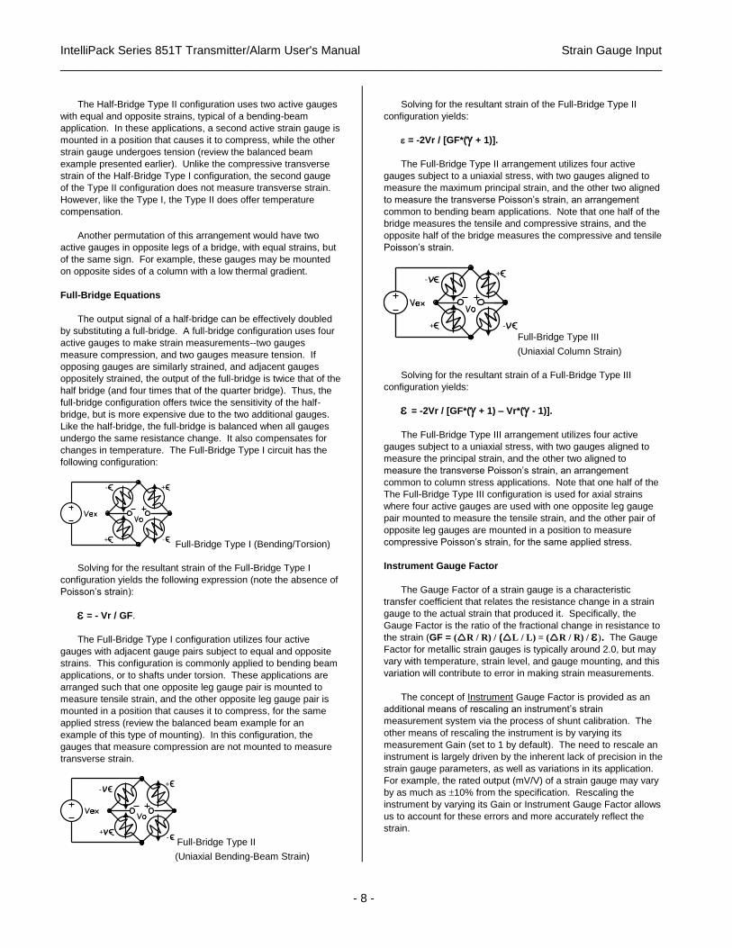
changes in temperature. The Full-Bridge Type I circuit has the
following configuration:
-
- +
+ Full-Bridge Type I (Bending/Torsion)
Solving for the resultant strain of the Full-Bridge Type I
configuration yields the following expression (note the absence of
Poisson’s strain):
= - Vr / GF.
The Full-Bridge Type I configuration utilizes four active
gauges with adjacent gauge pairs subject to equal and opposite
strains. This configuration is commonly applied to bending beam
applications, or to shafts under torsion. These applications are
arranged such that one opposite leg gauge pair is mounted to
measure tensile strain, and the other opposite leg gauge pair is
mounted in a position that causes it to compress, for the same
applied stress (review the balanced beam example for an
example of this type of mounting). In this configuration, the
gauges that measure compression are not mounted to measure
transverse strain.
-
+
+
-
Full-Bridge Type II
(Uniaxial Bending-Beam Strain)
Solving for the resultant strain of the Full-Bridge Type II
configuration yields:
= -2Vr / [GF*( + 1)].
The Full-Bridge Type II arrangement utilizes four active
gauges subject to a uniaxial stress, with two gauges aligned to
measure the maximum principal strain, and the other two aligned
to measure the transverse Poisson’s strain, an arrangement
common to bending beam applications. Note that one half of the
bridge measures the tensile and compressive strains, and the
opposite half of the bridge measures the compressive and tensile
Poisson’s strain.
+-
-+
Full-Bridge Type III
(Uniaxial Column Strain)
Solving for the resultant strain of a Full-Bridge Type III
configuration yields:
= -2Vr / [GF*( + 1) – Vr*( - 1)].
The Full-Bridge Type III arrangement utilizes four active
gauges subject to a uniaxial stress, with two gauges aligned to
measure the principal strain, and the other two aligned to
measure the transverse Poisson’s strain, an arrangement
common to column stress applications. Note that one half of the
The Full-Bridge Type III configuration is used for axial strains
where four active gauges are used with one opposite leg gauge
pair mounted to measure the tensile strain, and the other pair of
opposite leg gauges are mounted in a position to measure
compressive Poisson’s strain, for the same applied stress.
Instrument Gauge Factor
The Gauge Factor of a strain gauge is a characteristic
transfer coefficient that relates the resistance change in a strain
gauge to the actual strain that produced it. Specifically, the
Gauge Factor is the ratio of the fractional change in resistance to
the strain (GF = (R / R) / (L / L) = (R / R) / ). The Gauge
Factor for metallic strain gauges is typically around 2.0, but may
vary with temperature, strain level, and gauge mounting, and this
variation will contribute to error in making strain measurements.
The concept of Instrument Gauge Factor is provided as an
additional means of rescaling an instrument’s strain
measurement system via the process of shunt calibration. The
other means of rescaling the instrument is by varying its
measurement Gain (set to 1 by default). The need to rescale an
instrument is largely driven by the inherent lack of precision in the
strain gauge parameters, as well as variations in its application.
For example, the rated output (mV/V) of a strain gauge may vary
by as much as 10% from the specification. Rescaling the
instrument by varying its Gain or Instrument Gauge Factor allows
us to account for these errors and more accurately reflect the
strain.
IntelliPack Series 851T Transmitter/Alarm User's Manual Strain Gauge Input
___________________________________________________________________________________________
- 9 -
During shunt calibration, the strain measurement is modified
by varying the Instrument Gauge Factor until the reading matches
a pre-calculated (simulated) strain. The calculation of the
simulated strain is driven by the Gauge Factor of the strain gauge
itself and a fixed gain of 1. The instrument’s indicated strain is
driven by the Instrument Gauge Factor and the Measurement
Gain. Initially, the Instrument Gauge Factor is set equivalent to
the Strain Gauge Factor, but may differ following shunt
calibration. Thus, the Instrument Gauge Factor is an arbitrary
transfer coefficient that can be changed “on the fly” to convert the
input signal to an accurate indicated strain at the module. Any
changes to the Gauge Factor must also be followed by changes
to the Instrument Gauge Factor.
IMPORTANT: The Instrument Gauge Factor of this module is
initially set equivalent to the strain Gauge Factor which is initially
set to 2.000 by default. Thus, the indicated strain measurement
will be considered equivalent to the measured strain for a strain
gauge factor of 2. However, if the strain gauge factor GF 2 and
its value changes, the Instrument Gauge Factor must also
change or the indicated strain will be in error. The Instrument
Gauge Factor is normally set equivalent to the Gauge Factor,
then fine tuned via shunt calibration. You need to be aware that
changes in Gage Factor only drive the calculation of simulated
strain, but changes in the Instrument Gauge Factor drive the
module’s indicated strain. Alternately, the IntelliPack
Configuration Software includes a Software Gain Factor that may
be used to directly scale the indicated strain to the simulated
strain during shunt calibration. The Software Gain Factor is
initially set to 1.0 by default, but may be varied as required to
rescale strain measurements following shunt calibration.
Note that with respect to the display of strain for bridge inputs
via this module, the formulas presented are used internally by this
module, except Instrument Gauge Factor is substituted for Gauge
Factor, and the result is multiplied by a software Gain Factor for
rescaling purposes (default gain is 1.000).
Determining Your Sensor Type
This module supports two input types: strain gauge bridge
inputs for advanced strain measurement, or load cells for basic
force measurements. Examples of load cell inputs include
pressure transducers, torque converters, accelerometers, and
vibration sensors. These devices may operate under
compression and/or tension and yield bipolar or unipolar millivolt
signals proportional to the applied force. Load cell signals are
expressed in percent of span units for this module and do not
require you to know any additional details of the internal bridge
type, the gauge factor, or a materials Poisson’s ratio, as may be
required for strain gauge bridge inputs. Only the rated output and
nominal excitation are considered for load cells. On the other
hand, bridge inputs will use microstrain units and the formulation
for strain is more complex and will require knowledge of these
parameters and their application.
Bridge Inputs
The IntelliPack Configuration Software supports strain
formulation for all quarter, half, and full bridge types described
above. The following information is included to alleviate some of
the confusion encountered in selecting the proper strain
formulation for bridge input applications.
Note that all inputs to the 851T module are wired as complete
full-bridge circuits with remote sense lines included. The number
of active gauges, their purpose, and whether bridge completion is
already provided or done internally will determine the applicable
strain formula.
In any bridge configuration, it is the number of active load
cells in the bridge that determine whether it is a half, quarter, or
full-bridge. Additionally, the specific bridge type is determined by
considering the mounting of any additional load cells in the bridge
(i.e. their purpose), the presence of a “dummy” gauge, and
whether or not half-bridge completion resistors are provided.
Thus, the first step to determine which bridge type applies to
your application is to know how many active load cells are
present. An “active” cell is mounted such that it will measure
strain in the same direction as an applied force (either tensile or
compressive). One active load cell will form a Quarter-Bridge,
two active load cells will form a Half-Bridge, and four active load
cells will form a Full-Bridge.
If your bridge has one active gauge and no additional dummy
gauges or resistive elements present, then you select a Quarter-
Bridge Type I formulation. However, If your sensor has one
active gauge, plus a second passive or “dummy” gauge mounted
transverse to the applied stress (to provide temperature
compensation), then you select Quarter Bridge Type II. In any
case, the same formula for calculating strain applies to both
Quarter-Bridge types and the type distinction simply serves to
specify whether the gauge is temperature compensated or not,
and the steps that are necessary to complete the wiring for the
full-bridge input of the 851T module. For example, both types will
require half-bridge completion resistors (either external or
internal), and Type I will require that a third resistor be connected
in an adjacent arm to the active gauge and selected to match the
resistance of the active gauge.
If your bridge has two active gauges, with the second active
gauge mounted perpendicular to the applied force to measure the
coincident transverse (Poisson’s) strain and to temperature
compensate the primary active gauge (the gauge mounted to
measure strain in the same direction as the applied force), then
you would select a Half-Bridge Type I formulation. This is
commonly used to measure uniaxial strains at higher stress
levels, where the effect of the transverse strain is greater and
must be accounted for. Note that the Half-Bridge Type I circuit is
similar to the Quarter-Bridge Type II, except that the transverse
mounted gauge also measures the transverse Poisson’s strain as
well as temperature compensates the primary active gauge.
If your bridge has two active gauges, with both gauges
mounted such that they are subject to equal and opposite strains
for the same applied force, then you would select a Half-Bridge
Type II formulation. This is commonly used in bending-beam
applications, where one gauge is mounted in a position that
causes it to compress while the other gauge undergoes tension.
The presence of the second active gauge does provide
temperature compensation, but does not measure transverse
strain. Additionally, this type will require half-bridge completion
resistors and these may be wired externally, or provided internally
via the 851T module.

IntelliPack Series 851T Transmitter/Alarm User's Manual Strain Gauge Input
___________________________________________________________________________________________
- 10 -
If your bridge has four active gauges, with adjacent gauge
pairs subject to equal and opposite strains for the same applied
stress, then you would select a Full-Bridge Type I formulation.
This arrangement is inherently temperature compensated and
does not require bridge completion.
If your bridge has four active gauges, with one half of the
bridge (adjacent gauge pair) mounted to measure the tensile and
compressive strain, and the opposite half mounted to measure
the coincident transverse Poisson’s Strains, then you would
select a Full-Bridge Type II formulation. This type is commonly
used to measure the uniaxial stress in bending beam
applications. This arrangement is inherently temperature
compensated and does not require bridge completion.
If your bridge has four active gauges, with one diagonal
gauge pair mounted to measure the principal tensile strain, and
the opposite diagonal gauge pair mounted to measure the
transverse (compressive) Poisson’s Strain, then you would select
a Full-Bridge Type III formulation. This type is commonly used
to measure the uniaxial stress in a column. This arrangement is
inherently temperature compensated and does not require bridge
completion.
Table 3 below summarizes each of the bridge configurations
discussed, along with their respective strain formulation,
applications, and wiring. These equations apply for the bridge
output voltage in the polarity shown. Where applicable, if the
bridge completion resistors connect to IN+ instead of IN- you
effectively flip the polarity of the bridge output voltage and you
may remove the negative sign preceding each equation. The
convention illustrated in this document assumes a positive strain
is tensile and will correspond to a negative bridge output voltage.
Load Cell Inputs A simpler form of the Wheatstone bridge is the load cell. The
load cell is a device principally used in weighing systems that
utilizes strain gauge technology internally. Unlike the strain
gauge, the output of a load cell will be expressed in equivalent
units of force (not microstrain). As a result, processing a load cell
signal does not require intimate knowledge of its bridge type,
gauge factor, or Poisson’s ratio. Rather, the important
considerations of a load cell are its rated output (mV/V), its
excitation, and its rated capacity.
Note that even though the load cell itself will contain permutations
of quarter, half, or full-bridges, this detail is irrelevant and rarely
provided by the manufacturer. Further, most load cells have
bridge completion and temperature compensation already built-in.
Example 1: A compression load cell has six connection wires
(sense, excitation , and signal ) and is specified as follows:
Rated Capacity: 50,000 lbs/inches
Full-Scale Output: 2.0mV/V
Rated Excitation: 10V DC, 15V Maximum
Safe Overload: 150% Full-Scale
Operating Temperature Range: -65F to 200F
From these specifications, we can conclude the following: • This load cell is temperature compensated (wide ambient).
• The cell already includes half-bridge compensation resistors
internally (note the wiring—most common for this cell type).
• The output of this load cell is +20mV at full rated load of
50000psi with 10V of excitation (2.0mV/V * 10V).
• The output may be over-driven to +30mV at a load of
75000psi with 10V of excitation (safe overload limit).
Table 3: Summary Of Bridge Types, Their Strain Formulation, Applications, and Wiring
ACTIVE GAUGES
BRIDGE TYPE (N)
STRAIN FORMULATION (PRIMARY APPLICATION)
BRIDGE WIRING
1 Quarter-Bridge Type I
N=1
-4Vr * (1 + Rl / Rg) / [GF*(1+2Vr)] Uniaxial Compressive Strain In Constant Temperature Environments
A Single Gauge Paired With A Matching Resistor and Half-Bridge Completion Resistors.
1 Quarter-Bridge Type II
N=1
-4Vr * (1 + Rl / Rg) / [GF*(1+2Vr)] Uniaxial Compressive Strain With Changing Ambient Environmental Temperatures, most common in weigh-scale load cells
A Single Gauge Paired With A Transverse Mounted “Dummy” Gauge for Temperature Compensation and Half-Bridge Completion Resistors.
2 Half-Bridge Type I
N=1+
-4Vr * (1 + Rl / Rg) / [GF*(1+ ) - 2Vr*( - 1)] Uniaxial Strain at Higher Stress Levels
A Primary Gauge Paired with a Transverse Gauge To Measure Poisson’s Strain and Provide Temperature Compensation. Requires Half-Bridge Completion Resistors.
2 Half-Bridge Type II
N=2
-2Vr *(1 + Rl / Rg) / GF = -4Vr*(1 + Rl / Rg) / N*GF Bending Strain with Two Gauges Subject to Equal and Opposite Strains
One Gauge Measures Compression and Other Gauge Measures Tension For Same Applied Force. Requires Half-Bridge Completion Resistors.
4 Full-Bridge Type I N=4
-Vr / GF = -4Vr / (N*GF) Bending Beam Strain or Shafts Under Torsion with Gauge Pairs Measuring Equal and Opposite Strains
One Opposite Leg Pair Measures Compression, While Other Opposite Leg Pair Measures.
4 Full-Bridge Type II
N= 2(1+ )
-2Vr / [GF*( + 1)] = -4Vr / (N*GF) Uniaxial Column Strain with One Gauge Pair Measuring the Principal Tensile and Compressive Strains and the Opposite Gauge Pair Measuring the Corresponding Transverse Poisson’s Strains
One Half of Bridge Measures the Principal Tensile and Compressive Strain, Other Half Measures the Coincident Compressive and Tensile Poisson’s Strains.
4 Full-Bridge Type III
N= 2(1+ )
-2Vr / [GF*( + 1) – Vr*( - 1)] Uniaxial Column Strain with One Gauge Pair Measuring the Principal Tensile Strain and the Opposite Gauge Pair Measuring the Compressive Transverse Poisson’s Strain
One Opposite Gauge Pair (Diagonal) Measures Principal Tensile Strain and Other Opposite Gauge Pair Measures the Compressive Transverse Poisson’s Strain.

IntelliPack Series 851T Transmitter/Alarm User's Manual Strain Gauge Input
___________________________________________________________________________________________
- 11 -
2.0 PREPARATION FOR USE
UNPACKING AND INSPECTION
Upon receipt of this product, inspect the shipping carton for
evidence of mishandling during transit. If the shipping carton is
badly damaged or water stained, request that the carrier's agent
be present when the carton is opened. If the carrier's agent is
absent when the carton is opened and the contents of the carton
are damaged, keep the carton and packing material for the
agent's inspection. For repairs to a product damaged in
shipment, refer to the Acromag Service Policy to obtain return
instructions. It is suggested that salvageable shipping cartons
and packing material be saved for future use in the event the
product must be shipped.
This module is physically protected
with packing material and electrically
protected with an anti-static bag during
shipment. However, it is
recommended that the module be
visually inspected for evidence of
mishandling prior to applying power.
This circuit utilizes static sensitive
components and should only be
handled at a static-safe workstation.
INSTALLATION
The transmitter module is packaged in a general purpose
plastic enclosure. Use an auxiliary enclosure to protect the unit in
unfavorable environments or vulnerable locations, or to maintain
conformance to applicable safety standards. Stay within the
specified operating temperature range. As shipped from the
factory, the unit is factory calibrated for all valid input ranges and
has the default configuration shown in Table 2 at right (shaded
entries apply to alarm-equipped Model 851T-1500).
WARNING: Applicable IEC Safety Standards may require that
this device be mounted within an approved metal enclosure or
sub-system, particularly for applications with voltages greater
than or equal to 75VDC or 50VAC.
Refer to Table 2. Your application may differ from the default
configuration shown and will require that the transmitter be
reconfigured to suit your needs. This is accomplished with
Acromag’s user-friendly Windows 95/98/2000 or NT
Configuration Program and Serial Port Adapter. Configuration is
normally done prior to field installation since field configurability
via the module’s push-buttons is generally limited to zero, full-
scale, setpoint, and dropout adjustments. Note that Tare offset
generation can also be triggered remotely in the field via a wired
digital input signal at the TRIG & COM inputs (asserted high).
Table 2: 851T Default Factory Configuration
Parameter Configuration/Calibration
Input Type Load Cell
Gauge Resistance 350
Strain Gauge Factor 2.0000
Poisson’s Ratio 0.285
Gauge Rated Output 3mV/V
Excitation Source Internal
Nominal Excitation 10V
Software Gain Factor 1.0000
Gauge Factor 2.0000
Instrument Gauge Factor 2.0000
Initial Bridge Offset 0.000mV
Tare Offset 0.000mV
Digital Input Function Tare
Bridge Completion None (Jumper Removed)
Samples N=1 (No Input Averaging)
Output Range 0 to 10V DC (Jumper Installed)
Output Mode Normal (Ascending) Signal.
Transmitter Scaling Input for 0% Output = 0mV, Input for 100% Output = 30mV.
Optional Computation None (Directly Proportional)
Alarm Mode High Limit
Setpoint +30mV
Deadband 0.3mV (1%)
Operating Mode Failsafe
Time Delay 200ms
Reset Type Automatic (momentary)
Jumper Installation (For Voltage Output Only)
For voltage output, a short jumper must be installed between
the output “I+” and “JMP” terminals. A jumper wire has been
included with the unit and is already installed between the “JMP”
and I+ terminals. Verify jumper installation if your application
requires output voltage. Remove this jumper for current output
applications. Refer to the Electrical Connections Drawing
4501-886.
Bridge Completion Jumper Installation
(Refer To Drawing 4501-887)
This model includes two precision (2K 0.1%), low TC
(10ppm), half-bridge resistors that are ratio-matched to 0.02%,
plus jumper terminals to facilitate bridge completion for half &
quarter bridge applications. Quarter-bridge completion will also
require that an external wired resistor or “dummy” gauge (not
supplied) be installed close to the active gauge. Refer to Drawing
4501-887 for examples of these types of connections.
There are two industry conventions with respect to the
polarity of the bridge output voltage and the bridge completion
resistors of this module may accommodate both. Recall that a
positive strain is “tensile” and a negative strain is compressive.
With the bridge polarities illustrated and the bridge completion
jumper taken to the IN- lead, a positive strain will correspond to a
negative bridge output voltage and this is the convention
assumed in this manual. However, with the bridge output polarity
flipped and the bridge completion jumper taken to the IN+ lead
instead, a positive strain will correspond to a positive bridge
output voltage and this is an alternate industry convention.
Connect the HALF terminal to the adjacent IN- or IN+ terminal, as
required for your application.

IntelliPack Series 851T Transmitter/Alarm User's Manual Strain Gauge Input
___________________________________________________________________________________________
- 12 -
For half and quarter bridge completion, connect a jump wire
from TB2-2 (HALF) to TB2-1 (IN-), or TB2-3 (IN+), as required for
your application with respect to the polarity of the bridge output
voltage. Remove this jumper for full bridge connections. Note
that the TB2-2 (HALF) terminal may connect the intersection of
the internal half bridge resistor network to the bridge’s IN- or IN+
terminal. This is done to support the convention of some
equipment manufacturer’s which may use an alternate
relationship with respect to the bridge output signal. This is
normally apparent by noting the polarity of the lead that the half-
bridge completion resistors are connected to. Where applicable,
this manual assumes that the half-bridge completion resistors are
taken to the IN- lead and that a negative bridge output voltage will
accompany a positive strain. If you adopt the opposite
convention, flip the sign of the strain formulas provided such that
a positive bridge output signal will accompany a positive strain.
IMPORTANT: If you are simulating a strain gauge input signal
via a precision millivoltage source, then you must install this
jumper to properly bias the input signal or your measurement will
be in error.
Additionally, for quarter bridge completion, an external wired
resistor or “dummy” gauge must be installed close to the active
gauge to minimize unwanted temperature effects. This resistor is
usually selected to closely match the active gauge resistance and
is typically 120, 350, or 1000. This resistor is not provided
with your module as it must be selected to closely match your
active gauge impedance and temperature performance, making
pre-selection impractical.
Remote Tare Adjustment
Auto-tare is built into this module and allows the cancellation
or “taring” of non-zero dead weight or other sensor offsets. For
example, it is commonly used to remove the weight of a container
from a load cell measurement. It may also be used to correct for
imbalances in the input bridge or load cell circuitry. This model
provides separate controls for zero balance and tare adjustment.
Tare adjustment is accomplished two ways: via the [Tare]
push-button of the Configuration Software Test Page, or via an
asserted digital input signal at the isolated input. The Tare trigger
is asserted high with a voltage from 15-30V with respect to COM
at the TRIG terminal. If your application requires frequent tare
adjustment in the field, then you will have to make provisions for
wiring to the TRIG and COM terminals as part of your installation.
Separately, you may also have to use the IntelliPack Software to
configure this digital input for tare, as it can alternately be used to
reset a latched alarm relay (it is set to trigger tare by default).
Note that a tare offset will take effect immediately, but is only
stored to non-volatile EEPROM memory after 10 seconds of
TRIG inactivity. If power is lost during this interim period, your
tare offset will be lost also. This may seem inconvenient, but is
done to help preserve the life of the EEPROM, while still allowing
you to change tare on the fly.
Shunt Calibration Control Wiring
This module includes provisions to accomplish shunt
calibration for a shunt calibration resistor located at the module
and connected across the bridge resistor via dedicated leads.
Refer to Drawing 4501-886.
For convenience, you can mount a shunt resistor between
the CR and CR/B terminals. Then connect a switch between the
SW terminal and your gauge (SW and CR are tied together
internally). The long leads of the gauge are connected from the
opposite end of the switch and the module’s CR/B terminal. This
allows you to switch a shunt resistor in and out of the circuit as an
aide in rescaling this instrument during shunt calibration.
Mounting
Refer to Enclosure Dimensions Drawing 4501-888 for
mounting and clearance dimensions.
DIN Rail Mounting: This module can be mounted on "T" type
DIN rails. Use suitable fastening hardware to secure the DIN rail
to the mounting surface. Units may be mounted side-by-side on
1-inch centers for limited space applications.
"T" Rail (35mm), Type EN50022: To attach a module to this
style of DIN rail, angle the top of the unit towards the rail and
locate the top groove of the adapter over the upper lip of the rail.
Firmly push the unit towards the rail until it snaps solidly into
place. To remove a module, first separate the input terminal
block(s) from the bottom side of the module to create a clearance
to the DIN mounting area. Next, insert a screwdriver into the
lower arm of the DIN rail connector and use it as a lever to force
the connector down until the unit disengauges from the rail.
Electrical Connections
Input, output, power, & relay terminals can accommodate
wire from 12-24 AWG, stranded or solid copper. Strip back wire
insulation 1/4-inch on each lead before installing into the terminal
block. Input wiring should ideally be shielded twisted-pair. Since
common mode voltages can exist on signal wiring, adequate wire
insulation should be used and proper wiring practices followed.
It is recommended that transmitter output and power wiring be
separated from the input signal wiring for safety, as well as for
low noise pickup. Note that input, power, output, and relay
terminal blocks are a plug-in type and can be easily removed to
facilitate module removal or replacement, without removing
individual wires. If your application requires voltage output, you
must install a jumper between the output “I+” and “JMP”
terminals--this jumper is installed at the factory and should be
removed for current output applications. Always remove power
and/or disable the load before unplugging terminals to uninstall
the module, installing or removing jumpers, or before attempting
service. All connections must be made with power removed.
CAUTION: Risk of Electric Shock - More than one disconnect switch may be required to de-energize the equipment before servicing.
1. Power: Refer to Electrical Connections Drawing 4501-886.
Variations in power supply voltage within rated limits has
negligible effect on module accuracy. For supply
connections, use No. 14 AWG wires rated for at least 75C.
The power terminal is series diode-coupled for reverse
polarity protection. 2. Input: Connect input per Electrical Connections Drawing
4501-886. Observe proper polarity when making connections
(see label for input type).
IntelliPack Series 851T Transmitter/Alarm User's Manual Strain Gauge Input
___________________________________________________________________________________________
- 13 -
IMPORTANT: If the module is powered up prior to
completing the input connections, the self-calibration routine
will cause an offset error to be present once the input
connections are completed. You may correct this error by
resetting the module or cycling power after completing the
input connections. It is recommended that you always
complete the input connections prior to applying power.
External Excitation: If you wish to use your own power
supply to excite the bridge, you must first turn the internal
excitation supply OFF. This module uses a method of
ratiometric conversion in which the A/D reference is derived
from the excitation supply voltage. As such, you must also
complete the remote sense circuit by connecting your
excitation supply to the input sense leads (SEN+ and SEN-).
Refer to Drawing 4501-887 for more information. Bridge Completion: If your load cell requires half or quarter
bridge completion and you wish to employ the internal half-
bridge circuit, then you must also install a jumper between
the TB2-1 (IN-) & TB2-2 (HALF) terminals [or TB-3 (IN+) &
TB2-2 (HALF) terminals]. For quarter bridge completion, you
will also need to connect an external resistor or “dummy
gauge” near the active gauge as shown in Drawing 4501-887.
Refer to Bridge Completion section for more information.
Millivolt Source: If you are using a precision millivoltage
source to simulate a strain gauge input signal, or you have
selected the millivoltage input range, you must also install a
jumper between the TB2-1 (IN-) & TB2-2 (HALF) terminals to
properly bias the input signal. Additionally, the SEN+ and
EXC+ terminals are jumpered together, and the SEN- and IN-
terminals are jumpered together. The millivolt range is the
product of the Gauge Rated Output (mV/V) and the
excitation voltage settings. If simulating a load cell or bridge
signal, you should also program an excitation voltage
equivalent to that desired in your final application, as the A/D
reference voltage is derived from the excitation voltage.
Optional TRIG Wiring: TRIG is an optically isolated digital
input that may be used to trigger an auto-tare conversion, or
to alternately reset a latched alarm relay, as configured via
the IntelliPack software. A voltage from 15-30V with respect
to COM at the TRIG terminal is sufficient to assert TRIG.
The tare offset measurement will be subtracted from all
subsequent bridge or load cell measurements until a new tare
conversion is done or the software’s [Reset Tare] button is
clicked.
Optional Shunt Wiring: This module includes anchor
connections for an external shunt resistor and switch that
may be used to enable and disable a shunt element during
shunt calibration. Refer to Electrical Connections Drawing
4501-886 for examples of these connections. 3. Analog Output Connections: Wire the output as shown in
Electrical Connections Drawing 4501-886. For the voltage
output, you must also install a jumper between the output “I+”
and “JMP” terminals (installed at the factory). Remove this
jumper for current output.
Note: For sensitive applications, high frequency noise may be reduced via a 0.1uF capacitor placed across the load.
4. Output Relay Contacts: Wire relay contacts as shown in
Electrical Connections Drawing 4501-886. See the “Alarm
Relay Specifications” for power capacity.
If necessary, an interposing relay can be used to switch
higher currents as shown in the Interposing Relay Connection
Drawing 4501-646.
Electromechanical Relay Contact Protection: To maximize relay life with inductive loads, external protection is required. For DC inductive loads, place a diode across the load (1N4006 or equivalent) with cathode to (+) and anode to (-). For AC inductive loads, place a Metal Oxide Varistor (MOV) across the load. See Relay Contact Protection Drawing 4501-646 for details. IMPORTANT: Noise and/or jitter on the input signal has the effect of reducing (narrowing) the instrument’s deadband and may produce contact chatter. The long term effect of this will reduce the life of mechanical relays. To reduce this undesired effect, you should increase the effective deadband. Note that the input averaging function of this transmitter may also be used to reduce contact chatter, but at the expense of increasing the effective response time.
5. Grounding: See Electrical Connections Drawing 4501-886.
The module housing is plastic and does not require an earth
ground connection. Input EXC- may be earth grounded.
WARNING: For compliance to applicable safety and performance standards, the use of shielded cable is recommended as shown in Drawing 4501-886. Further, the application of earth ground must be in place as shown in Drawing 4501-886. Failure to adhere to sound wiring and grounding practices may compromise safety & performance.
3.0 CALIBRATION AND ADJUSTMENT
This transmitter/alarm module needs to be configured for
your application. Complete configuration is normally
accomplished using Acromag’s Windows 95/98/2000 or NT
IntelliPack Configuration Program and Serial Port Adapter. This
software provides controls for calibrating various aspects of the
input module and the strain gauge sensor. Additionally, field
controls for adjustment of transmitter zero, full-scale/span, alarm
setpoint, & alarm dropout/deadband are provided. Controls for
field tare offset generation and the remote reset of latched alarm
relays are also provided. The operation of these controls are
described in the following paragraphs.
MODULE CALIBRATION
The IntelliPack Configuration Software includes calibration
controls for reference voltage and divider calibration, plus
excitation endpoint calibration. These adjustments have already
been performed at the factory and readjustment may not be
required, except as necessary to verify operation or to satisfy
your company’s maintenance requirements.
This module uses a ratiometric conversion method in which
the A/D reference voltage is derived from a voltage divider
connected across the variable excitation supply. Thus, the input
signal is sampled simultaneously ratiometric to the reference,
when the input is wired as a Wheatstone Bridge. That is, the
input signal and the A/D reference are both directly proportional
to the bridge excitation voltage. A second A/D channel samples
a fixed internal reference voltage and uses the resultant
measurement to precisely determine the programmed excitation
level.

IntelliPack Series 851T Transmitter/Alarm User's Manual Strain Gauge Input
___________________________________________________________________________________________
- 14 -
This software includes controls for calibrating this reference,
calibrating the bridge excitation voltage span, and for calibrating
the resistor divider applied to the bridge excitation voltage that is
used to generate the A/D reference. Provisions for
accomplishing shunt calibration are also provided.
IMPORTANT: Allow the module to warmup several minutes prior to perfoming calibration. If the internal excitation is used, this supply should be loaded with the equivalent resistance of the gauge or load cell prior to calibrating its endpoints.
Reference Calibration
(This Calibration Must Be Performed Prior To Divider Cal)
The A/D includes a fixed reference voltage internally
connected to channel 2. It periodically samples the channel 2
voltage to derive the excitation level and the corresponding A/D
reference voltage. The initial reference voltage at channel 2 may
vary slightly from 1.225V, and as a result, its voltage must be
accurately measured and input to the firmware of the module. A
small 2-pin header is internally connected across this reference
for measurement via a DVM. The cover must be removed to gain
access to this header. Note that this voltage has already been
calibrated at the factory and readjustment is not normally
necessary.
CAUTION: If you choose to make this readjustment and take this measurement, you must use strict ESD handling procedures. Otherwise, the sensitive internal circuitry could be easily damaged via ESD or an inadvertent short.
To calibrate this reference, precisely measure the voltage
across P1 (cover removed). Type the measured value into the
Reference Voltage Calibration Value field of the Module
Calibration screen, then click the Calibrate button to store the
measurement. Note that the relative accuracy of your module is
strongly dependent upon the accuracy of this measurement.
Divider Calibration (Must Follow Reference Calibration)
An internal divider is comprised of precision 0.1% resistors
and connected across the excitation supply voltage (at the SEN
terminals) in order to generate the A/D reference. The reference
error due to the initial tolerance of these resistors can be
accounted for by precisely measuring the excitation voltage
across the SEN+ and SEN- terminals, then loading this value into
the module via the Configuration Software. The module will
compare its own internal calculation of the excitation voltage with
your measured value, and then make adjustments to the divider
ratio as required.
Simply measure the excitation voltage across the SEN
terminals, then input your measured value into the Divider Ratio
Calibration Value field of the Input Calibration screen. Then click
on the Calibrate button to store this value. The new ratio will be
indicated. Again, note that the relative accuracy of your module
is strongly dependent on the accuracy of this measurement.
Excitation Voltage Calibration
The internal excitation supply is varied via the resistance of a
digital potentiometer tied to an adjustable regulator. This pot has
an initial tolerance of 20% which will cause the upper endpoint
of the excitation to vary between 11 and 15V.
As such, the excitation endpoints must be precisely calibrated in
order for the module to be able to make accurate excitation
adjustments to user-programmable levels. This calibration
directly determines the incremental excitation voltage or
adjustment resolution (93mV typical), which is the span of this
adjustment divided by 99 (a 100 value digital pot is used).
For best results, the excitation supply should be loaded with
the equivalent resistance of your bridge or load cell before taking
voltage measurements. Likewise, allow the module to warm-up
prior to calibration. Note that the excitation supply has already
been calibrated at the factory with a 350 load. If your load
differs significantly from this, you may increase measurement
accuracy via recalibration. Simply click the “Min Exc Voltage”
button of the Input Calibration screen to send the excitation
supply to its minimum point. Measure the excitation voltage via a
DVM connected across the EXC terminals. Type the measured
value into the Excitation Voltage Low Calibration Value field, then
click on the Calibrate button to store the endpoint. Repeat this
process for the “Max Exc Voltage” value.
IMPORTANT: If you choose to recalibrate the excitation supply endpoints, then you should do this with the excitation supply loaded with the equivalent impedance of your bridge or load cell. Allow the module to warmup several minutes prior to calibration. Ideally, the module should be at an ambient temperature close to that of its final application.
SENSOR CALIBRATION
The IntelliPack Configuration Software also includes controls
to null bridge offsets and perform shunt calibration. Additionally,
controls are provided for adjusting the excitation level, setting
tare, and calibrating the output. Only the controls unique to this
model are reviewed in the following paragraphs. Refer to the
Transmitter Configuration Manual for information on controls and
adjustments common to all IntelliPacks.
Bride Balancing/ Offset Nulling
Most bridge circuits fail to output exactly 0 volts with no strain
applied. Slight variations in resistance among each arm of a
bridge and between the leads will contribute to some initial
(unstrained) offset voltage. This offset may also be due to
thermoelectric voltages generated in the circuit wiring, or via
external noise sources.
The IntelliPack Configuration software includes software
controls to null bridge offsets to zero. For example, you can null
compensate your bridge or load cell by taking an initial
measurement before strain is applied to your system, then
clicking the Input Null button of the software to store the
unstrained non-zero output signal. This offset will be subtracted
from subsequent signal measurements, until a new Null Offset
voltage is stored or the software Reset Null function is invoked.
Note that input Null automatically subtracts any current non-
zero offset before writing a new value to the module. However,
this is only applied correctly if the same input type is used, bridge
or load cell. That is, if you wish to change input types and you
already have a non-zero null offset stored, then you should click
the [Reset Null] button prior to changing input types or your
subsequent measurements will be in error.

IntelliPack Series 851T Transmitter/Alarm User's Manual Strain Gauge Input
___________________________________________________________________________________________
- 15 -
This is because the null offset is stored in the engineering units of
the input type--bridge types use microstrain, while load cells use
percent-of-span.
Note that an offset null conversion is similar to a tare
conversion, and null offsets could be conveniently combined with
tare, but only if you first use Reset Null to set any initial bridge
offset to zero. However, if you choose to combine the unstrained
bridge offset with the tare offset, then you will not be able to
extract the actual tare weight from a measurement. Note that
tare measurements are typically much larger than bridge
imbalances, as tare may take any value within the range of the
input. By combining null with tare, a non-zero strain will be
indicated with no applied stress (module indication will not return
to zero with the load and tare removed). The ability to separate
bridge offsets from tare is also useful in judging the operation of a
bridge or load cell, as large bridge offsets are sometimes
indicative of sensor problems. Additionally, tare may change
values frequently for a given load cell, while the bridge imbalance
usually remains constant for the measuring system. For these
reasons, it is usually more convenient to keep tare offsets
separate from bridge offsets and this module provides separate
controls for both.
If your bridge imbalance is especially large, you may wish to
determine if the offset is indeed due to a bridge imbalance, or to
some other external effect like thermoelectric voltage or noise. If
you simply remove the excitation from the bridge, the bridge
output should be zero. If the bridge output indicated is non-zero
with no applied excitation, and if this value is significant, then this
output is unrelated to the strain measurement and some effort
should be made to identify and remove the source of this error.
Note however, that the 851T performs a ratiometric conversion of
the bridge output and the A/D reference is generated from the
excitation supply. Thus, the excitation voltage must be present
between the remote sense leads (SEN+/SEN-) to make a
measurement. That is, you can disconnect the EXC and SEN
terminals from the bridge, but you must keep the EXC wires
connected to their adjacent SEN terminals to complete the circuit
(assuming internal excitation). Additionally, the bridge completion
jumper must be present to properly bias the resultant “floating”
bridge signal. Any resultant non-zero signal measurement under
these conditions can be then attributed to other external effects. Shunt Calibration
Shunt calibration is a process by which the module’s
sensitivity is rescaled by adjusting the module’s Instrument
Gauge Factor and/or its Gain, such that its indicated
measurement matches a calculated (simulated) “ideal” strain.
The term is a misnomer here as it does not actually calibrate the
module or the strain gauge, but rather the effective sensitivity of
the strain measurement system.
To accomplish shunt calibration, a large known resistance
value (not provided) is placed parallel with one of the arms of the
bridge to reduce the effective resistance of the arm and simulate
a strain. Note that the shunt resistor does not necessarily have
to shunt the active gauge, and in some cases, it may be more
convenient to shunt another bridge element. The magnitude of
the response will be the same, but the sign of the indicated strain
will vary according to the bridge element shunted.
The shunt will affect the bridge output either positively or
negatively, depending on the leg of the bridge that is shunted. If
the measured response is not equivalent to the calculated strain
with the shunt applied, then the module’s sensitivity is typically
rescaled by varying the Instrument Gauge Factor and/or Software
Gain until the two values converge.
From the above figure, recall that when R1/R2 = Rg/R3, the
output will be zero and the bridge is said to be balanced. A
negative change in bridge output will result by shunting R1 or R3
(decreasing R1/R2, increasing Rg/R3). Likewise, a positive
change in bridge output results from shunting Rg or R2
(decreasing Rg/R3, increasing R1/R2). For the polarities shown,
a positive change in bridge output voltage will result when Rshunt
is applied across Rg. The resultant strain obtained by shunting
Rg with Rs will be negative (resistance decreases). The general
convention is that positive strain is tensile, and negative strain is
compressive. Thus, a positive bridge output voltage will result
from a decrease in the Rg leg resistance which will produce a
negative strain (compressive). This is the convention used
throughout this manual.
Note that the shunt resistance (Rs) and simulated microstrain
(Es) are related via the following equation (applicable at
simulated strains less than 2000 microstrain):
Rs = [Rg * 106 / (GF * N * Es)] - Rg
In this equation, Rg is the resistance of the shunted gage
arm, typically the nominal bridge resistance (i.e. 120, 350, or
1000). N is a factor used to account for the presence of multiple active gauges in a bridge circuit (see table below). Es refers to the simulated strain in microstrain units and its sign is omitted. Note that GF refers to the Gauge Factor of the strain gauge, and not the Instrument Gauge Factor used by the module.
N Bridge Type
1 Quarter Bridge Type I & II
1 + Half-Bridge Type I
2 Half-Bridge Type II
2 * (1 + ) Full-Bridge Type II & III
4 Full-Bridge Type I
Note that the factor N can also be used to correct the strain
simulated via a strain indicator calibrator. Typically, you would
divide the calibrator’s “dial” indication by N to get the actual strain
seen by the module with its configuration set to the corresponding
bridge type.
To calculated the simulated strain (Es) in micro-strain units
solve the equation above for Es as follows:
Es (micro-strain) = - Rg * 106 / (GF* N* (Rs+Rg)
If the lead-wire resistance (Rl) is sufficiently large in comparison to the shunt resistance such that 100*Rl/Rs > 0.1 * (required calibration precision in percent), then the following calculation for Rs is more precise (note the additional term):

IntelliPack Series 851T Transmitter/Alarm User's Manual Strain Gauge Input
___________________________________________________________________________________________
- 16 -
Rs = [Rg * 106 / (GF * N * Es)] – Rg – 2 * Rl
To apply these equations, it is assumed that the resistance of
each leg of the bridge is equal and the bridge is balanced prior to
performing shunt calibration. Note that the strain simulated by
shunting Rg with Rs is always negative (compressive) and the
negative sign is commonly omitted.
In performing shunt calibration, the simulated strain Es is
calculated as shown and compared to the actual measured value
of the module. If the two values differ significantly, then the
measured response of the module can be rescaled by varying the
module’s Instrument Gauge Factor or Software Gain, until the
indicated output properly registers the calculated (simulated)
strain. That is, the effect of shunt calibration is to rescale the
module’s sensitivity, and this process is also referred to as
Instrument Scaling.
To accurately perform shunt calibration, you should apply the
shunt at the bridge, and not at the instrument. However, in some
cases it may not be convenient to apply the shunt at the gauge.
If the shunt resistor is local to the instrument, then you must
provide separate leads to the bridge resistor that is to be shunted
(these leads must be of equal length and gauge). For your
convenience, this module provides screw terminals for installation
of a shunt calibration resistor, plus connections to a switch in
order to enable or disable the shunt. Refer to Electrical
Connections Drawing 4501-886.
The IntelliPack Configuration Software provides an entry field
for your shunt resistance (Rs), as well as a field that is used to
identify the leg or bridge resistor that is shunted for a specific
bridge configuration (the calibration element). A graphic figure is
shown with reference designators for the standard quarter, half,
and full bridge configurations. Fields for Instrument Gauge
Factor and Software Gain Factor are also provided. A calculator
is also built in to calculate the required shunt resistance for a
specific simulated strain. With the shunt resistance applied to the
bridge element, you simply click the “Update” button which will
use the parameters you provided to calculate a simulated strain
(this calculation uses the actual strain Gauge Factor and a fixed
gain of 1.0), and simultaneously sample the input voltage and
indicate its measurement using the same parameters, except the
indicated value is computed with the Instrument Gauge Factor
substituted for the strain Gauge Factor and the result is multiplied
by the software Gain Factor. Typically, you would adjust the
Instrument Gauge Factor and/or Gain Factor as required, and
again click “Update”, until your indicated measurement closely
approximates the simulated value (internally calculated). Varying
the software Gain Factor or Instrument Gauge Factor effectively
adjusts the instrument’s sensitivity for its indication of relative
strain.
The IntelliPack Configuration Software includes a built-in Shunt Resistor Calculator that will calculate a required shunt resistance for a specific simulated microstrain. Keep in mind that the accuracy of the resistance and simulated strain calculations diminishes above simulated strains greater than about 2000 microstrain.
IMPORTANT: Shunt Calibration should only be performed on unstrained gauges. Bridge offsets should be nulled prior to shunt calibration. Always allow the module to warm up several minutes prior to performing shunt calibration.
The following table lists the simulated microstrain
(compressive) for various resistance values when shunted across
the active strain gauge of a quarter-bridge circuit (N=1) for 120
and 350 strain gauges. These values assume a gauge factor setting of 2.0000.
Table 3: Shunt Resistor & Simulated Strain (Quarter Bridge)
120 Gauges 350 Gauges
Shunt Microstrain Shunt Microstrain
1M 59.8 1M 174
599880 100 349650 500
200K 299 200K 872
119880 500 174650 1000
100K 598 100K 1744
59880 1000 87150 2000
50K 1197 50K 3476
29880 2000 57983 3000
20K 2978 43400 4000
19880 3000 34650 5000
14880 4000 20K 8510
11880 5000 17150 10000
5880 10000
Excitation Level Adjustment
This module employs a ratiometric input conversion method
that derives the A/D reference voltage from the variable excitation
voltage level. As a result, an indicated strain will remain relatively
constant as the value of the excitation voltage is changed.
The output of a bridge is directly proportional to the bridge
excitation voltage. Normally, the highest adjustment of bridge
excitation voltage should be used while taking into account the
gauge manufacturer’s recommendations and the negative effect
of self-heating in the bridge resistors.
The internal bridge excitation supply of this model can be
adjusted from roughly 4V to 10V at the bridge, and is driven via
an adjustable regulator whose output is controlled via a 100 value
digital pot. The excitation level at the bridge is sensed via the
remote sense lines to the bridge (SEN+ and SEN-). Remote
sensing will allow the module to boost the output level so that the
programmed excitation level is maintained at the remote bridge,
effectively correcting for any lead resistance drop. These lines
also drive the divider used to generate the reference to the A/D.
A fixed reference voltage input to a second channel of the A/D
(the actual A/D reference varies with excitation level) allows the
excitation level to be read back in closed loop fashion. This
permits the unit to make adjustments to the excitation level in
order to compensate for load, lead-wire, and temperature effects.
You simply enter the excitation level you desire, and the unit
adjusts to that level. The excitation supply also has sufficient
overdrive capability to allow up to 1V of total EXC lead resistance
drop. Note that in some cases, resolution limitations will only
allow the module to approximate your nominal excitation level,
typically to within 93mV. Higher than expected lead-wire
resistance may also limit the excitation level obtained at the
bridge. In any case, the software displays the actual excitation
level obtained at the bridge via the remote sense leads and this
may differ from your desired excitation.
IntelliPack Series 851T Transmitter/Alarm User's Manual Strain Gauge Input
___________________________________________________________________________________________
- 17 -
If you wish to drive your bridge via your own excitation
source, the IntelliPack Configuration Software allows you to turn
OFF the internal excitation supply. In this mode, you must limit
your excitation voltage between 4V and 11V DC. Do not exceed
these limits or damage to the unit may result. Keep in mind that
the A/D reference is generated via the excitation supply and you
must complete this circuit by including the EXC and SEN lead
connections, just as if you were using internal excitation.
Likewise, since the unit no longer has closed loop control of the
excitation voltage under these conditions, make sure that your
supply provides a clean, steady voltage to the bridge, or
measurement accuracy may be compromised. AC bridge
excitation is not permissible for use with this module.
WARNING: You must use the IntelliPack Configuration Software
to turn OFF the internal excitation supply BEFORE you connect
the unit to an external excitation source, or damage to the unit
may result. Do not exceed rated excitation voltage limits.
FIELD CONFIGURATION AND ADJUSTMENT
This program mode allows adjustment to key transmitter
calibration and alarm parameters in the field, without having to
connect a host computer. Field reprogrammability of zero & full-
scale (input to output scaling), plus alarm setpoint & deadband
(Model 851T-1500), is alternately accomplished via this
transmitter/alarm module’s “SET”, “MODE”, “UP”, and “DOWN”
push buttons, and the zero/full-scale and relay LED’s (see
Drawing 4501-888) as described here.
The following procedure uses the corresponding zero/full-
scale (labeled “Z/FS”) and relay (labeled “RLY”) LED’s to indicate
which parameter is being programmed. A constant ON zero/full-
scale LED refers to zero configuration (scaling input for 0%
output), a flashing ON/OFF zero/full-scale LED refers to full-
scale/span configuration (scaling input for 100% output). A
constant ON relay LED indicates setpoint adjustment, a flashing
ON/OFF relay LED indicates dropout/deadband adjustment.
Refer to Table 4.
Table 4: Field Configuration LED Program Indication
LED INDICATOR CONSTANT ON FLASHING
Yellow Zero/Full-Scale (labeled “Z/FS”)
Zero
Full-Scale
851T-1500 Only Yellow Relay
(labeled “RLY”),
High or Low
Setpoint
High or Low
Dropout
CAUTION: Do not insert sharp or oversized objects into the
switch openings as this may damage the unit. When depressing
the push-buttons, use a blunt tipped object and apply pressure
gradually until you feel or hear the tactile response.
IMPORTANT: This module performs a ratiometric conversion of
the input signal and the A/D reference is derived from the bridge
excitation voltage via the sense leads. Thus, the module requires
that the excitation and sense lead connections be intact in order
to complete a conversion. That is, simply connecting a millivolt
source to the input in order to simulate a bridge signal will not
work without also completing the excitation and sense wiring, and
installing the half-bridge completion jumper at TB2-1 & TB2-2 (to
properly bias the input source).
If using a precision millivoltage source to drive the input, it is
suggested that you also adjust the internal excitation source to a
level that will approximate your final application (the A/D
reference is derived from the excitation).
Prior to field calibration, the module’s input type, bridge
configuration, excitation level, and sensitivity must already be set
via the IntelliPack Configuration Software. Input levels outside of
150% of full rated load (excitation level multiplied by sensitivity)
will not be acceptable for zero, full-scale, setpoint, or dropout
calibration. Since input levels cannot be validated during field
programming, entering incorrect signals can produce an
undesired output response. Install a jumper between the output
“I+” and “JMP” terminals for voltage output, remove this jumper
for current output.
Equipment Required
A bridge calibrator, strain indicator calibrator, simulator, or
weights/dummy loads may be used as an input source.
Optionally, a precision millivolt source may also be used to drive
the input. In any case, the resultant signal source must be
accurate over the range required for zero and full-scale, and
alarm setpoint and dropout levels. Note: For best results, the input source must be accurate
beyond the required specifications. An accurate current or
voltage meter is also required to monitor the output level. Ideally,
this meter must be accurate beyond the module specifications.
Before attempting field calibration, consider that in the field,
the use of an application’s actual sensor, load cell, or bridge
arrangement can make field calibration impractical in some
cases, as it would require that precise calibration loads or
stresses be applied, including load equivalents for alarm levels,
as well as zero and full-scale. Further, the accurate simulation of
strain gauge bridges is often impractical due to wide variances in
their application and offsets. Complete calibration is most easily
accomplished via the IntelliPack Configuration Software.
Transmitter/Alarm General Field Programming Procedure
Field configuration of zero and full-scale via the front panel
push-buttons is essentially equivalent to the scaling operation
performed via the Transmitter Configuration page of the
IntelliPack software. That is, you define the input for 0% output,
and the input for 100% output. However, in field calibration, you
may map a minimum input signal to an output signal up to 20% of
nominal full-scale, and a maximum input signal to an output
signal from 60 to 110% of nominal full-scale. In other words, your
zero calibration may include offset (up to 20%) and you do not
have to use an equivalent full-scale load to accurately calibrate
your output response (you can use 60-110% of full-scale). You
may choose to include tare in your field zero calibration, but are
limited to 20% of full-scale. For greater tare weights, you can
always trigger tare offset generation in the field without limitation
via the digital input trigger (see Electrical Connections). Note: The bridge excitation level, the gauge rated output, and the
input type/wiring can only be set via the IntelliPack Configuration
Program. Calibration is optimally performed via the Intellipack
Software, but field program mode provides an alternate form of
input-to-output calibration by allowing you to scale virtually any
portion of the input range to the selected output range via the
front panel push buttons, and tare generation via the digital input.

IntelliPack Series 851T Transmitter/Alarm User's Manual Strain Gauge Input
___________________________________________________________________________________________
- 18 -
In the following example, assume that we are using a 2mV/V
compression cell rated for full output at 100lbs with nominal
excitation of 10V, and 50% over capacity. Thus, this load cell will
output +20mV when excited by 10V with 100lbs applied.
IMPORTANT: Field calibration operates on Xmtr Configuration
parameters and will change your “Input for 0% Output” and “Input
for 100% Output” software parameters. As such, you should
perform tare prior to calibrating the unit via the front-panel
pushbuttons.
Transmitter/Alarm Programming Procedure
1. Connect your load cell (or simulator) to the input, as required
(refer to Electrical Connections Drawing 4501-886). Be sure
to include the excitation and sense lead connections which
are required for ratiometric conversion. Also, connect a
precise current milliampmeter or voltmeter to read the output
signal from the transmitter.
2. Apply power and the module’s green “Run” LED will light.
3. Press and hold the “MODE” push button until the green
“Run” LED turns OFF and the yellow “Zero/Full-Scale” LED
turns ON. In this mode, the unit is ready to accept a zero
input for the transmitter (equivalent to the scaling input for
0% output). If you do not wish to change the zero
parameter, skip to step 7.
4. Adjust the input signal to the zero load equivalent (this value
must be within the range capability of the load cell). You
may choose an input equivalent up to 20% of full-scale. For
our example, assume this corresponds to a calibrated load
of 10% (10lbs or 2mV).
5. Press the “UP” or “DOWN” push-button once. Refer to the
Functional Block Diagram 4501-885 and note that internally,
the output of the Range Adjust Box is now set for 0.0% for
the input zero value of 10lbs (2mV). The transmitter will
adjust it’s output to the minimum output value (4.000mA).
If the measured output is not exactly at the zero level
(4.000mA), press the UP or DN switches continuously until
the desired output is achieved. You may adjust the output
up to 20% of full-scale.
Note: After first pressing the UP & DN push-buttons, they
will function as trim adjustments for the output stage. The
minimum output trim adjustment should be limited from
about 10% of full-scale around the nominal range endpoint.
Each successive depression of the “UP” or “DN” switch will
increment or decrement the output signal by a small
amount. Holding the switch depressed will increase the
amount of increment or decrement.
6. Press the “SET” push-button to accept the zero value.
Note that every time “SET” is pressed, the yellow “Status”
LED will flash once and the zero output will be captured.
7. Press the “MODE” push button one time. The yellow
“Zero/Full-Scale” LED will flash on/off, indicating that the unit
is ready to accept the full-scale value (equivalent to the
scaling input for 100% output). If you do not wish to change
this parameter, skip to step 11.
8. Adjust the input source to the full-scale load equivalent (the
input value must be less than 150% of full rated load and
greater than the zero value). For our example, assume this
corresponds to a calibrated load of 100lbs (20mV). Note: If
the zero and full-scale points are chosen too close together,
performance will be degraded.
Transmitter/Alarm Programming Procedure…continued 9. Press the “UP” or “DOWN” push-button once. Refer to
Functional Block Diagram 4501-885 and note that internally,
the output of the Range Adjust Box is now set for 100.0% for
the input full-scale value of 100% (100lbs or 20mV). The
transmitter will adjust it’s output to the maximum output
value (20.000mA). If the output is not exactly at the full-
scale level (20.000mA), press the UP or DN switches
continuously until the desired output is achieved.
You may adjust the output to a level from 60-110% of full-
scale. Note: After first pressing the UP & DN push-buttons,
they will function as trim adjustments for the output stage.
The maximum output trim adjustment should be limited from
60 to 110% of the nominal full-scale endpoint. Each
successive depression of the “UP” or “DN” switch will
increment or decrement the output signal by a small
amount. Holding the switch depressed will increase the
amount of increment or decrement.
10. Press the “SET” push-button to accept the full-scale value.
Note every time “SET” is pressed, the yellow “Status” LED
will flash once and the full-scale output will be captured.
11. If you are configuring an 851T-0500 model, which has no
alarm function, then you should skip steps 12-17 and jump
ahead to step 18.
12. Press the “MODE” push button one time until the yellow
zero/full-scale LED goes out and the yellow relay LED turns
ON (see Table 4). In this mode, the unit is ready to accept
an input setpoint level for the alarm. If you do not wish to
change the setpoint, skip to step 15.
Note: The setpoint can be set to any value within the input
range regardless of the zero/full-scale settings.
13. Adjust the input source to the High or Low alarm load
equivalent. For our example, assume 110% (110lbs or
22mV). This is your alarm setpoint level.
14. Press the “SET” push button to accept the setpoint. Note
that every time “SET” button is pressed, the yellow status
LED will flash once and the value at the input will be
captured.
15. Press the “MODE” push button one time and the yellow
relay LED should start flashing (see Table 4). This means
that the unit is ready to accept the dropout level for the
alarm relay. If you do not wish to change the dropout, skip
to step 18.
16. Adjust the input source to the desired dropout level load
equivalent. For our example, assume 100% (100lbs or
20mV).
17. Press the “SET” push button to accept the input dropout
level. Note that every time the “SET” button is pressed, the
yellow status LED will flash once and the value at the input
will be captured. The module will use the difference
between the setpoint and dropout values to calculate relative
deadband. For our example, this is 10% (10lbs or 2mV).
18. Press the “MODE” push button one time to complete the
program sequence and return to run mode. The green
“RUN” LED will turn ON, the yellow “Zero/Full-Scale” LED
will be OFF, and the yellow alarm LED will be on or off
according to the alarm status. The module will now assume a transfer function based on
the zero and full-scale values just set. The setpoint and
dropout of 851T-1500 units determines the alarm deadband.
IntelliPack Series 851T Transmitter/Alarm User's Manual Strain Gauge Input
___________________________________________________________________________________________
- 19 -
Note that field adjustment of zero and full-scale can
eliminate the need to perform separate null or tare offset
operations via the configuration software by combining the
offset(s) with field zero calibration (up to 20% of full-scale).
Tare offset generation may also be accomplished in the field
via the digital input trigger (see Electrical Connections). Note: If no buttons are pressed for a period greater than 3
minutes, the module will automatically revert to run mode
(green “Run” LED will light) and no changes will be made to
the zero, full-scale, and optional setpoint & dropout settings.
REMOTE/FIELD TARE OFFSET ADJUSTMENT
An optically isolated digital input is provided on this module
that may be wired to remotely trigger a tare offset conversion, or
to alternately reset a latched alarm relay (851T-1500 units only).
The operative function of this active-high input is defined via the
Configuration Software. By default, this input is set to function as
a trigger for tare offset conversions as described here.
Auto-tare allows the cancellation or “taring” of any non-zero
dead weight, or other sensor offsets, from input measurements.
It is commonly used to remove the weight of a container from a
load cell measurement, but could also be used to correct for
imbalances in the input bridge (if the bridge offset is set to 0).
Note that this module handles bridge and load cell offsets
separate from tare, but the effect of both operations is similar.
Normally, tare is easily accomplished by clicking on [TARE]
of the Configuration Software Test Page, but may be alternately
invoked in the field by wiring a voltage signal to the TRIG digital
input terminal provided on the module. A TRIG voltage from 15-
30V with respect to COM, is sufficient to trigger a tare conversion
of the input, but only if the digital input function has been set to
control tare. The new tare offset will take effect immediately after
deasserting TRIG, and will be stored in non-volatile EEPROM
memory only after 10 seconds of TRIG inactivity. The tare offset
will remain in effect for all input measurements until TRIG is
asserted again later, or the [Tare]/[Reset Tare] software buttons
are invoked. Note however, that TARE is not inclusive of itself—
that is, a tare measurement does not include any prior tare offset.
REMOTE/FIELD RESET OF LATCHED ALARMS
A digital input channel is provided on the module that may be
wired to remotely reset a latched alarm relay, or alternately trigger
a tare offset conversion (described above). This input is active-
high and its operative function is defined via the Configuration
Software. By default, this input is set to function as a trigger for
auto-tare, but may be alternately defined as a reset for a latched
alarm relay via the Configuration Software for 851T-1500 models.
Note that a latched alarm relay can be reset four ways: by turning
the power off momentarily, via software control, via the front-
panel push-buttons, or remotely via this digital input.
A TRIG voltage from 15-30V with respect to COM is sufficient
to assert the trigger and reset the latched alarm, but only if the
digital input function has been set to reset latched alarms via the
Configuration Software.
4.0 THEORY OF OPERATION
OPERATION OF THE 851T
Refer to Simplified Schematic 4501-884 and Functional Block
Diagram 4501-885 to gain a better understanding of the circuit.
This module conditions a single strain gauge bridge input or load
cell, provides alarm functionality, and generates a proportional
voltage or current output signal. The module uses a differential
input channel of an A/D to monitor the output signal of a
Wheatstone bridge.
The A/D reference voltage is derived from the bridge
excitation voltage via a voltage divider across the remote sense
signal terminals. An adjustable regulator is used to generate the
bridge excitation voltage and varies with the setting of a 100 point
digital potentiometer. The A/D input reading is a count value that
is a function of the bridge output voltage divided by the A/D
reference voltage and the A/D gain. The A/D converter performs
an analog-to-digital conversion of the input signal and digitally
filters the signal. The digitized signal is then serially transmitted
to a microcontroller. The microcontroller multiplies this count by
the A/D reference divider ( 9.09K/ 29.09K) to get the equivalent
count of the bridge output voltage divided by the bridge excitation
voltage. This count is then substituted for the Vr term of the
strain equation and a value of strain as a function of count is
calculated. This is then converted to strain units (bridge inputs)
or percent (load cells) and corrected for initial offset and tare to
produce a measured strain. As the input signal is ratiometric to
the A/D reference, the effect of simultaneously deriving the A/D
reference from the excitation voltage and measuring the bridge
output produces a ratiometric input conversion that is virtually
immune to changes in the excitation voltage. The microcontroller
completes the transfer function according to the input type and its
embedded program, then sends a corresponding output signal to
an optically isolated Digital-to-Analog Converter (DAC). The DAC
updates its current or voltage output in response. The
microcontroller also compares the signal value to the limit value
according to its alarm type, and completes all necessary alarm
functions per its embedded program (851T-1500 units only). A
second A/D input monitors a fixed reference voltage in order to
obtain the current excitation voltage via closed-loop feedback.
Since the A/D reference is related to the excitation voltage by a
voltage divider, the actual excitation voltage level can then be
calculated and verified against the value obtained by multiplying
the incremental value by the number of digital pot cycles required
to achieve the user-specified value (the incremental value is
obtained by dividing the adjustment span of the excitation voltage
range by 99 divisions).
The embedded configuration and calibration parameters are
stored in non-volatile memory integrated within the micro-
controller. However, only the functions required by an application
are actually stored in memory—new functionality can be
downloaded via the IntelliPack Configuration Software and the
Serial Port Adapter. A wide input switching regulator (isolated
flyback mode) provides an isolated excitation supply, isolated
+14V output circuit supply, and isolated +5V circuit power. Refer
to Functional Block Diagram 4501-885 for an overview of how the
software/push-button configuration variables are arranged.
IntelliPack Series 851T Transmitter/Alarm User's Manual Strain Gauge Input
___________________________________________________________________________________________
- 20 -
5.0 SERVICE AND REPAIR
CAUTION: Risk of Electric Shock – More than one disconnect switch may be required to de-energize the equipment before servicing.
SERVICE AND REPAIR ASSISTANCE
This module contains solid-state components and requires no
maintenance, except for periodic cleaning and verification of
configuration parameters (zero, full-scale, setpoint, deadband,
etc). Since Surface Mount Technology (SMT) boards are difficult
to repair, it is highly recommended that a non-functioning module
be returned to Acromag for repair. The board can be damaged
unless special SMT repair and service tools are used. Further,
Acromag has automated test equipment that thoroughly checks
and calibrates the performance of each module. Please refer to
Acromag’s Service Policy Bulletin or contact Acromag for
complete details on how to obtain service parts and repair.
PRELIMINARY SERVICE PROCEDURE
Before beginning repair, be sure that all installation and
configuration procedures have been followed. The unit routinely
performs internal diagnostics following power-up or reset. During
this period, all LED’s will turn ON momentarily and the green
“Run” LED will flash. If the diagnostics are successfull, the “Run”
LED will stop flashing after two seconds and remain ON,
indicating the unit is operating normally. If the “Run” LED
continues to flash, then this is indicative of a problem. In this
case, use the Acromag IntelliPack Configuration Software to
reconfigure the module and this will usually cure the problem. If
the diagnostics continue to indicate a problem via a continuously
flashing green LED, or if other evidence points to a problem with
the unit, an effective and convenient fault diagnosis method is to
exchange the questionable module with a known good unit.
The IntelliPack Serial Port Adapter also contains a red LED
visible at the small opening in the enclosure to the right of the
RJ11 receptacle. If this LED is OFF or Flashing and power is
ON, then a communication interface problem exists. Note that
the adapter receives its power from the IntelliPack module. A
constant ON LED indicates a properly working and powered
serial interface adapter. Note that problems may also arise if you
elect to make your own Intellipack cable and exceed about 6 feet
in length.
Acromag’s Application Engineers can provide further
technical assistance if required. When needed, complete repair
services are available from Acromag.
6.0 SPECIFICATIONS
General: The IntelliPack Model 851T-0500 is a DC-powered
transmitter which conditions either a single strain gauge
transducer or Wheatstone bridge input, and provides an
isolated voltage or current output. Isolation is supplied
between the inputs, the output, and power. Model 851T-1500
units also include a SPDT, Form C, electromechanical relay,
which provides a local limit alarm function with isolated relay
contacts. This transmitter/alarm is DIN-rail mounted.
The unit is configured and calibrated with our user-friendly
Window 95/98/2000 or NT IntelliPack Configuration
Program. Push-buttons on the module allow adjustment to
the zero and full-scale points for the transmitter, plus setpoint
and deadband, and may act as a latched alarm reset for
modules with the alarm option. An isolated digital input is
included to remotely trigger tare conversions, or to reset a
latched alarm relay. Non-volatile reprogrammable memory in
the module stores calibration and configuration information.
MODEL NUMBER DEFINITION
Transmitters are color coded with a white label. The prefix
“8” denotes the IntelliPack Series 800, while the “T” suffix
specifies that this device is primarily a process transmitter.
851T: Transmits and isolates a single strain gauge bridge or
load cell input signal (DC millivoltage). -X500: The four digits of this model suffix represent the following
options, respectively:
X = 1 with Alarm Relay, X = 0 without Alarm Relay; 5 = Output: Transmitter Voltage or Current; 0 = Enclosure: DIN rail mount; 0 = Approvals: cULus Listed.
INPUT SPECIFICATIONS
Unit must be properly wired and configured for the intended
input type and range (see Installation Section for details). All
inputs to this module must be wired as full bridges with remote
sense lines included. The unit can be configured to accept any of
seven strain gauge bridge types, plus millivoltage or load cell
inputs via the IntelliPack Configuration Program. The following
paragraphs summarize this model’s input types, ranges, and
applicable specifications.
Load Cell: Provides input (differential) leads, sense leads
(remote sense), and excitation leads (internal variable
supply), for connection to 6 or 7-wire load cells (up to
100mV). For connection to 4-wire load cells, you must
jumper the module’s excitation leads to the adjacent sense
leads (see Drawing 4501-886).
SG Bridge: Provides input (differential) leads, sense leads
(remote sense), and excitation leads (internal variable
supply), for connection to strain gauge bridges. Two versions
of quarter-bridge, two versions of half bridge, and three
versions of full-bridge are supported (also millivolts—see
below). Connections for half, and quarter bridge completion
are also provided. Not suitable for high-elongation strain
measurements.
Millivolt: Provides input (differential) leads for connection to a
millivolt signal source in range of 5mV to 100mV (100%).
The millivolt input is set as a Bridge Type selection after
selecting SG Bridge as the main Input Type. The millivolt
range itself is set via the bipolar product of your Gauge Rated
Output and Excitation Voltage settings. Note that you must
also jumper the module’s excitation leads to the adjacent
sense leads for millivoltage input. In addition, you must also
include a HALF bridge completion jumper to properly bias the
input signal source, or measurement error will result (see
Drawing 4501-886).

IntelliPack Series 851T Transmitter/Alarm User's Manual Strain Gauge Input
___________________________________________________________________________________________
- 21 -
IMPORTANT: Complete input connections prior to
applying power. If the module is powered up prior to
completing the input connections, the initial self-calibration
routine will cause an offset error to be generated once the
input connections are completed. You may correct this error
by then resetting the module, or cycling the power with
complete input connections.
Input Units: SG Bridge input signals are expressed in
microstrain units (except millivolts). Load Cell signals are
expressed in percent of span units. Millivolt inputs use
millivolt units.
Input Reference Test Conditions: 120 Bridge; 10V
Excitation; 2mV/V Rated Output; 20mV (100%) input
range; 25C ambient; 24VDC Power; 200ms Alarm Delay.
Input Span/Range: All input ranges are bipolar and
determined from the product of the gauge’s rated output
and the excitation voltage selection.
Input Over-Range: The actual internal input range is 150%
typical of the range obtained via the product of the gauge’s
rated output and the excitation selected.
Input Accuracy: Better than 0.1% of span typical, for
bipolar ranges larger than or equal to 10mV. This includes
the effects of repeatability and terminal point conformity, but
does not include sensor error. Accuracy noted refers to input
measurement & alarm, but does not include output accuracy.
Input Sensitivity: Accepts gauge rated outputs from 1mV/V
to 10mV/V. The input signal range is the bipolar product of
your excitation voltage and your gauge’s rated output.
Input Impedance (Minimum): IN at 1M, SEN at 29K.
Input Bias Current: 1nA typical at IN.
Input Lead Resistance: Module has sufficient overdrive to
guaranty 10V of bridge excitation with 5/lead and 100mA of
excitation current. Larger lead resistances or higher currents
will limit the maximum bridge excitation that can be achieved.
Input Lead Break Detection: Output will be driven upscale
within 1.5s for “wire-harness” failure (all 6 or 4 leads open).
Output moves upscale for a single IN+ lead break, and
downscale for a single IN- lead break. The output will move
upscale for all other individual and combination wire failures,
except for SEN- alone, and SEN- with IN+.
Note (Lead Break Detection w/ External Excitation): If you
are using an external excitation supply, you must jumper the
module’s EXC excitation terminals to their adjacent SEN
sense terminals to properly detect sense lead breakage.
Note that the sense lead wiring is still required with external
excitation, as the A/D reference for this model is derived from
the excitation supply voltage delivered via the SEN leads.
Input Bridge Excitation (Internal): Adjustable from 4V to
11V (100 points), up to 120mA. For maximum rated ambient
temperature, the bridge resistance should be greater than or
equal to 350. For bridge resistance from 350 down to
120, limit maximum ambient to 60C. For applications with
an effective bridge resistance between 87.5 (four parallel
350 bridges) and 120, the maximum ambient temperature
should be limited to 50C. Lower bridge resistances may
cause the internal excitation to thermal limit. Use of optional
external bridge excitation does not limit the maximum
ambient below 70C. Internal excitation must be turned OFF
for external excitation supply connections. The internal
excitation voltage will be automatically boosted if it drops by
approximately 60mV.
Input Bridge Excitation (External): 4V to 11V. Internal
excitation must be turned OFF prior to connection to an
external excitation supply. IMPORTANT: Do not connect the input terminals to any external excitation voltages unless you have first used the Configuration Software to turn the internal excitation supply OFF. Failure to follow this procedure may damage the internal excitation supply.
Input Tare: Auto-tare is built in and can be triggered
remotely via the TRIG digital input (200ms minimum active-
low pulse), or via controls of the IntelliPack Configuration
Software. Auto-Tare is commonly used to remove the weight
of a container from a load cell measurement. The equivalent
tare is automatically removed from subsequent input
measurements until TRIG is asserted again later to trigger a
new tare conversion. The Tare offset takes effect
immediately, but is only written to non-volatile EEPROM
memory after 10 seconds of TRIG input inactivity. This is
done to preserve the life of the EEPROM, while still allowing
tare to change on the fly. Note that tare measurement is not
inclusive of itself and does not include any prior tare offset. General Input Specifications
Accuracy: Ambient Temperature Effect: Better than
±0.01% of input span per C (100ppm/C), or
1.0uV/C, whichever is greater.
Resolution: The effective resolution will vary according to
your rated output (mV/V), excitation voltage, and input
type selection. For example, with an excitation voltage of
10V and a rated output of 2mV/V, the internal range is
150%, or 1.5*0.002*10 = 0.030V. The A/D reference
voltage is (9.09/29.09)*10V = 3.125V. The ideal gain is
Vref/Range = 3.125/0.030 = 104, but is limited to the
nearest available gain of the A/D, or 64 (from 1, 2, 4, 8,
16, 32, or 64). The A/D will return a count value
according to the formula for bipolar mode: Count =
32768*Vin*Gain/Vref + 32768. Thus, a full-scale input of
20mV will generate an internal count of 46190 (from
32768*64*0.02/ 3.125 + 32768). The effective resolution
is derived as follows:
Load Cell Input Type: The 0-100% span is 46190-32768,
or 13422. Thus, the internal resolution for this case is 1
part in 13422 (0.0074%). However, the actual (display)
resolution for this example is limited to two digits after the
decimal point if expressed in percent, or 0.01%.
SG Bridge Input Type: From the bipolar mode equation,
Vin/Vref = (Count –32768)/(32768 * Gain), and Vref=
(9.09/29.09) * Vexc. Thus, Vin/Vexc = (9.09/29.09)*
(Count-32768)/32768*Gain) and this is the Vr term of the
strain equations (for a balanced bridge). Thus, for a
quarter bridge with Rlead=0, strain = -4 * Vr /
[GF*(1+2Vr)], or –3982 microstrain at 20mV (100%).
Thus, the effective internal resolution is 1 part in 3982, or
0.025%. Note that the actual (display) resolution is 1
microstrain. If the SG Bridge was a Full-Bridge Type I,
the strain = 999 microstrain, and the effective
resolution for our example is reduced to 1 part in 999.
Response Time: Measurement: 120ms typical; Analog
Output: 280ms typical to within 0.1% of the final value
for a step change in the input. This assumes input
averaging is set to “1” (response time will increase as the
input averaging number is increased). See Relay
Response Time for alarm output response.
Input Filter Bandwidth: -3dB at 30Hz, typical.
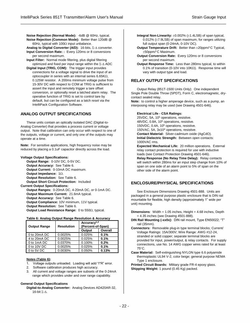
IntelliPack Series 851T Transmitter/Alarm User's Manual Strain Gauge Input
___________________________________________________________________________________________
- 22 -
Noise Rejection (Normal Mode): -6dB @ 60Hz, typical.
Noise Rejection (Common Mode): Better than 120dB @
60Hz, typical with 100 input unbalance.
Analog to Digital Converter (A/D): 16-bits, - converter.
Input Conversion Rate: : Every 120ms or 8 conversions
per second maximum.
Input Filter: Normal mode filtering, plus digital filtering
optimized and fixed per input range within the - ADC
Digital Input (TRIG, COM): The trigger input provides
connections for a voltage signal to drive the input of an
optocoupler in series with an internal series 6.65K,
0.125W resistor. A 200ms minimum voltage pulse from
15-30V DC with respect to COM at TRIG is sufficient to
assert the input and remotely trigger a tare offset
conversion, or optionally reset a latched alarm relay. The
operative function of TRIG is set to control tare by
default, but can be configured as a latch reset via the
IntelliPack Configuration Software.
ANALOG OUTPUT SPECIFICATIONS
These units contain an optically isolated DAC (Digital-to-
Analog Converter) that provides a process current or voltage
output. Note that calibration can only occur with respect to one of
the outputs, voltage or current, and only one of the outputs may
operate at a time. Note: For sensitive applications, high frequency noise may be
reduced by placing a 0.1uF capacitor directly across the load.
Voltage Output Specifications:
Output Range: 0-10V DC, 0-5V DC.
Output Accuracy: See Table 6.
Output Current: 0-10mA DC maximum.
Output Impedance: 1.
Output Resolution: See Table 6.
Output Short Circuit Protection: Included
Current Output Specifications:
Output Ranges: 0-20mA DC, 4-20mA DC, or 0-1mA DC.
Output Maximum Current: 21.6mA typical.
Output Accuracy: See Table 6.
Output Compliance: 10V minimum, 11V typical.
Output Resolution: See Table 6.
Output Load Resistance Range: 0 to 550, typical.
Table 6: Analog Output Range Resolution & Accuracy
Output Range
Resolution
Accuracy1,2
(Percent-of-Span)
Output Overall
0 to 20mA DC 0.0025% 0.025% 0.1%
4 to 20mA DC 0.0025% 0.025% 0.1%
0 to 1mA DC 0.0370% 0.100% 0.2%
0 to 10V DC 0.0025% 0.025% 0.1%
0 to 5V DC 0.0030% 0.050% 0.13%
Notes (Table 6):
1. Voltage outputs unloaded. Loading will add “I*R” error.
2. Software calibration produces high accuracy.
3. All current and voltage ranges are subsets of the 0-24mA
range which provides under and over range capability.
General Output Specifications
Digital-to-Analog Converter: Analog Devices AD420AR-32,
16-bit -.
Integral Non-Linearity: 0.002% (1.4LSB) of span typical,
0.012% (7.9LSB) of span maximum, for ranges utilizing
full output span (0-24mA, 0-10V DC).
Output Temperature Drift: Better than 20ppm/C Typical,
50ppm/C Maximum.
Output Conversion Rate: Every 120ms or 8 conversions
per second maximum.
Output Response Time: Less than 280ms typical, to within
0.1% of transition (0-10V into 10K). Response time will
vary with output type and load.
RELAY OUTPUT SPECIFICATIONS
Output Relay (851T-1500 Units Only): One independent
Single Pole Double Throw (SPDT), Form C, electromagnetic, dry-
contact sealed relay.
Note: to control a higher amperage device, such as a pump, an
interposing relay may be used (see Drawing 4501-646).
Electrical Life - CSA Ratings:
25VDC, 5A, 105 operations, resistive.
48VDC, 0.8A, 105 operations, resistive.
150VDC, 0.4A, 105 operations, resistive.
150VAC, 5A, 3x10⁴ operations, resistive.
Contact Material: Silver-cadmium oxide (AgCdO).
Initial Dielectric Strength: Between open contacts:
1000VAC rms.
Expected Mechanical Life: 20 million operations. External
relay contact protection is required for use with inductive
loads (see Contact Protection Drawing 4501-646).
Relay Response (No Relay Time Delay): Relay contacts
will switch within 280ms for an input step change from 10% of
span on one side of an alarm point to 5% of span on the
other side of the alarm point.
ENCLOSURE/PHYSICAL SPECIFICATIONS
See Enclosure Dimensions Drawing 4501-888. Units are
packaged in a general purpose plastic enclosure that is DIN rail
mountable for flexible, high density (approximately 1” wide per
unit) mounting.
Dimensions: Width = 1.05 inches, Height = 4.68 inches, Depth
= 4.35 inches (see Drawing 4501-888).
DIN Rail Mounting (-xx0x): DIN rail mount, Type EN50022; “T”
rail (35mm).
Connectors: Removable plug-in type terminal blocks; Current/
Voltage Ratings: 15A/300V; Wire Range: AWG #12-24,
stranded or solid copper; separate terminal blocks are
provided for input, power/output, & relay contacts. For supply
connections, use No. 14 AWG copper wires rated for at least
75C.
Case Material: Self-extinguishing NYLON type 6.6 polyamide
thermoplastic UL94 V-2, color beige; general purpose NEMA
Type 1 enclosure.
Printed Circuit Boards: Military grade FR-4 epoxy glass.
Shipping Weight: 1 pound (0.45 Kg) packed.

IntelliPack Series 851T Transmitter/Alarm User's Manual Strain Gauge Input
___________________________________________________________________________________________
- 23 -
APPROVALS
cULus Listed, UL File E199702.
Product approval is limited to general safety requirements of
the above standards.
Warning: This product is not approved for hazardous location
applications.
ENVIRONMENTAL SPECIFICATIONS
Operating Temperature: -25C to +70C (-13F to +158F) with
external excitation, or with internal excitation and bridge
impedance greater than or equal to 350. Limit maximum
ambient to +60C with bridge impedance below 350 down
to 120, and +50C with bridge impedance below 120
down to 83. Lower bridge impedance may cause the
excitation supply to thermal limit.
Storage Temperature: -40C to +85C (-40F to +185F).
Relative Humidity: 5 to 95% non-condensing.
Power Requirements: 12-36V DC SELV (Safety Extra Low
Voltage), 11.5VDC minimum. Current draw is a function of
supply voltage, excitation current, output load, and circuit
load (relay energized, SPA connected). Currents indicated in
Table 8 assume the bridge excitation is driving 10V into 120
(83mA), the voltage output circuit is at 10V into 1K (10mA),
the relay is energized (851T-1500 only), and the Serial Port
Adapter is connected. An internal diode provides reverse
polarity protection.
CAUTION: Do not exceed 36VDC peak, to avoid
damage to the module.
Table 8: 851T Supply Current
Supply 851T-0500 851T-1500 (Relay Energized)
12V 315mA 350mA
15V 250mA 275mA
24V 145mA 160mA
36V 105mA 115mA
Note: Supply current will be significantly reduced by
reducing the excitation current and/or disconnecting the
Serial Port Adapter.
IMPORTANT: Do not power-up or reset the module without
first completing the input connections or the internal self
calibration routine will generate an input offset error. If this
occurs, reset the module or cycle power once the input wiring
is complete to re-invoke self calibration.
IMPORTANT: - External Fuse: If unit is powered from a
supply capable of delivering more than 1A to the unit, it is
recommended that this current be limited via a high surge
tolerant fuse rated for a maximum current of 1A or less
(for example, see Bel Fuse MJS1).
Power Supply Effect:
DC Volts: Less than 0.001% of output span change per
volt DC for rated power supply variations.
60/120 Hz Ripple: Less than 0.01% of output span per volt
peak-to-peak of power supply ripple.
Isolation: Input, output, and power circuits are isolated from
each other for common-mode voltages up to 250VAC, or
354V DC off DC power ground, on a continuous basis (will
withstand 1500VAC dielectric strength test for one minute
without breakdown). Optional relay outputs are isolated from
other circuits up to 150VAC, or 150VDC.
This complies with test requirements of ANSI/ISA-82.01-1988
for the voltage rating specified.
Installation Category: Designed to operate in an Installation
Category for use in a Pollution Degree 2 environment.
(Overvoltage Category ll rating).
Radiated Field Immunity (RFI): Complies with IEC1000-4-3
Level 3 (10V/M, 80 to 1000MHz AM & 900MHz keyed) and
European Norm EN50082-1.
Electromagnetic Interference Immunity (EMI): No relay trips
will occur beyond 0.25% of input span from setpoint and no
output shifts will occur beyond 0.25% of span under the
influence of EMI from switching solenoids, commutator
motors, and drill motors.
Electrical Fast Transient Immunity (EFT): Complies with
IEC1000-4-4 Level 3 (2KV power; 1KV signal lines) and
European Norm EN50082-1.
Electrostatic Discharge (ESD) Immunity: Complies with
IEC1000-4-2 Level 3 (8KV/4KV air/direct discharge) to the
enclosure port and European Norm EN50082-1.
Surge Immunity: Complies with IEC1000-4-5 Level 3 (2.0KV)
and European Norm EN50082-1.
Radiated Emissions: Meets or exceeds European Norm
EN50081-1 for class B equipment.
FIELD CONFIGURATION AND CONTROLS
Field programming of transmitter zero and full-scale (all
models), plus alarm setpoint and dropout levels (851T-1500
only), and tare is accomplished with module push-buttons and
LED indicators.
Note: The unit must be initially configured via the Configuration
Software before its configuration can be varied in the field. Tare
conversion should be done prior to field calibration.
Module Push Buttons (See Dwg. 4501-643 For Location):
Mode - Used to change mode of field configuration.
Set - Used to accept input data during field calibration.
Up (Reset) - Used to increment output level during field
calibration. Used to reset a latched alarm relay in
operating mode.
Down (Reset) - Used to decrement output level during field
calibration. Used to reset a latched alarm relay in
operating mode.
TRIG Digital Input Terminals (Auto-Tare or Latch Reset):
TRIG – Active-high, isolated digital input trigger used to
remotely trigger a tare offset conversion, or alternately
reset a latched alarm relay. A 15-30V voltage from TRIG
to COM is sufficient to assert this trigger (6V typical).
The TRIG terminal has a resistor of 6.65K in series with
an opto-coupler. Be sure to limit power dissipation in this
resistor to 0.125W or less. Note, if TRIG is held high, the
tare function will be repeated continuously.
COM – Common for TRIG digital input signal.
LED Indicators (Operating Mode):
Run (Green) - Constant ON indicates normal operation and
power is applied. Flashing ON/OFF indicates unit is

IntelliPack Series 851T Transmitter/Alarm User's Manual Strain Gauge Input
___________________________________________________________________________________________
- 24 -
performing diagnostics (first second following power-up),
or has failed diagnostics (after a few seconds).
Status (Yellow) - Flashing ON/OFF indicates an open sensor
or that the input is outside of the selected input range. A
constant ON indicates the input is outside of the
transmitter’s calibrated input range.
Zero/Full-Scale (Yellow) - OFF in Run mode.
Relay (Yellow) - Constant ON indicates alarm condition for
relay. During field configuration, this LED has a different
function (see below).
LED Indicators (Field Configuration Mode):
Run (Green) - Turned OFF in this mode.
Status (Yellow) - Flashes each time the “SET” push button is
pressed to capture an I/O signal in this mode.
Zero/Full-Scale (Yellow) - ON or FLASHING in this mode if
zero or full-scale is being adjusted (See Table 4).
Relay (Yellow) - ON or FLASHING if alarm setpoint or
dropout is being adjusted (See Table 3) in this mode.
HOST COMPUTER COMMUNICATION Host Communication Port (SPI): IntelliPack SPI port (standard
RJ11 6-wire phone jack). See Drawing 4501-643 for location.
Configuration information is downloaded from the host
computer through one of its EIA232 serial ports. This port
must be connected to the module through an Acromag
IntelliPack Serial Port Adapter. This Serial Port Adapter
serves as an isolated interface converter between EIA232
and the IntelliPack’s SPI port.
Baud Rate (EIA232): 19.2K baud.
SOFTWARE CONFIGURATION
Units are fully reprogrammable via our user-friendly Windows
95/98/2000 or NT IntelliPack Configuration Program (Model
5030-881). A cable (5030-902) and converter (5030-913) are
required to complete the interface (Software Interface Package
800C-SIP). See Drawing 4501-643.
In addition to configuring all features of the module, the
IntelliPack Configuration Software includes additional capabilities
for testing and control of this module as follows:
• Monitors the input signal (microstrain or percent), excitation
voltage, A/D reference voltage, and output signal values.
Also monitors the input type, excitation source, input
sensitivity, input range, null offset, and tare offset. Allows
polling to be turned on or off.
• Allows a configuration to be uploaded or downloaded to/from
the module and provides the means to rewrite a module’s
firmware if the microcontroller is replaced or the module’s
functionality is updated.
• Provides controls to separately calibrate the input circuit, the
output, and the excitation supply. Also provides controls to
perform shunt or load calibration, and controls to restore the
original factory input or output calibration in case of error.
• Provides controls to adjust the bridge excitation voltage.
• Provides controls to null initial bridge or load cell offsets.
• Provides controls to perform shunt or load calibration to
re-scale the instrument’s indicator by modifying its gain
and/or instrument gauge factor.
• Provides controls to trigger a tare conversion of the input
signal (can also be done remotely via wired digital input).
• Provides controls to reset a module and reset a latched
alarm (a latched alarm may also be reset remotely via wired
digital input, or locally via front-panel push-buttons).
• Provides a control to adjust a transmitter’s output signal
independent of the input signal.
• Allows optional user documentation to be written to the
module. Documentation fields are provided for tag number,
comment, configured by, location, and identification
information. This information can also be uploaded from the
module and printed via this software.
• Allows a module’s complete configuration to be printed in an
easy to read, two-page format, including user
documentation.
The following transmitter and alarm attributes are
configurable via the IntelliPack Configuration Software. The
descriptions provided are organized with respect to their
appearance in the corresponding configuration pages of the
IntelliPack Software. You may also refer to the IntelliPack
Transmitter Configuration Manual (8500-570) for additional
details regarding configuration attributes.
General Configuration
Input – Type: Select SG Bridge or Load Cell (see Determining
Your Sensor Type). Note that the Strain Gauge Bridge type
assumes the input is wired in the Wheatstone bridge format
and will express its output in microstrain units. The Load Cell
type assumes a 6-wire connection to the load cell and will
express the output in percent-of-span units. Four-wire load
cells may be accommodated (see Drawing 4501-886). Select
SG Bridge if you wish to configure a millivolt input.
Input – Samples: Select the number of input samples (A/D
conversions) for calculation of an average (select 1/default, 2,
4, 8, or 16) before processing the signal. Increasing samples
is useful for help in filtering transients. Note that the effective
response time will be increased by the factor selected. Both
the alarm relay and transmitter output will use the averaged
value and their response times will be affected accordingly.
Input – Digital Function (851T-1500 Only): Select the
functionality of the digital input to trigger tare (default), or to
reset a latched alarm relay. The digital input is asserted high
by a voltage from 15-30V. On 851T-0500 units, this input is
used only to remotely trigger a tare conversion.
Output - Range: Unit can be configured for either a voltage or
current output range. A jumper must also be installed
between the output “I+” and “JMP” terminals for voltage
output (remove this jumper for current output).
Voltage: 0 to 10V DC, 0 to 5V DC
Current: 0 to 20mA DC, 4 to 20mA DC, or 0 to 1mA DC
Output - Mode: Select a normal acting (ascending), or reverse
acting (descending) output response.
Strain Gauge Bridge/Load Cell Setup
Bridge – Type/Conversion (Not Applicable for Load Cell):
Select from two versions of Quarter-Bridge input conversion,
two versions of Half-Bridge input conversion, and three
versions of Full-Bridge inputs, or millivolts. A graphic of the
bridge type will be displayed including reference designators
and the applicable strain formula.
Note: The selection of quarter or half bridge types will also
require installation of the HALF jumper at TB2, if internal half-
bridge completion resistors are used. Millivolt inputs will also
require that this jumper be installed. In addition, quarter
bridge conversion also requires the installation of an external

IntelliPack Series 851T Transmitter/Alarm User's Manual Strain Gauge Input
___________________________________________________________________________________________
- 25 -
resistor or “dummy gauge” (not supplied). See Bridge
Completion section for additional details.
Bridge/Load Cell – Rated Output: Enter the rated output of the
bridge or load cell as specified by the manufacturer in
millivolts per volt of excitation. The product of the rated
output and the excitation will determine your signal range.
The resultant Range is indicated to the right of this field.
Bridge/Load Cell – Signal Range: This field displays the
product of the excitation and the gauge’s rated output (all
ranges are bipolar). It does not include the 50% over-range
capability already built-in. Note that the transmitter output
may be separately scaled to utilize only a portion of the
available range if so desired.
Note: Large bridge offsets and the inability to precisely tune
your selected excitation level can limit the effective input
signal range to a value below the nominal range indicated.
Bridge/Load Cell – Excitation Source: Select “Int” for Internal
(default), or “Ext” for External. Selecting External will disable
the internal adjustable regulator.
IMPORTANT: You must set this parameter to “Ext” before
connecting an external excitation source to the module or
damage to the unit’s internal excitation supply may occur.
Note that the new setting is assumed following download.
Bridge/Load Cell – Nominal Excitation: If the excitation source
is set to Internal, then this field allows you to specify a
nominal excitation level from 4V to 11V, typical. The actual
(measured) excitation is read back via the remote sense lines
and displayed separately on the Test Page. Note that the
nominal excitation may differ from the measured value due to
limitations with adjustment resolution and any larger than
expected lead resistance. Likewise, the firmware may
periodically boost the excitation if it drops below level.
Bridge – Gauge Resistance (Not Applicable to Load Cells):
Enter the nominal gauge resistance as specified by the
gauge manufacturer. For the purposes of strain calculation, it
is assumed that all gauges and/or resistors of quarter and
full-bridge applications have the same resistance.
Bridge – Lead Resistance (Not Applicable to Load Cells):
This is the lead resistance of the excitation and sense leads
to the gauge in ohms. All leads are assumed to be of the
same gauge and length.
Note: The excitation supply provides sufficient overdrive
voltage to support 10V at the bridge, with up to 5 of lead
resistance and currents up to 100mA.
Bridge – Gauge Factor (Not Applicable to Load Cells): Enter
the Gauge Factor of the strain gauge as specified by the
manufacturer. The default gauge factor is set to 2.000. Do
not confuse this Gauge Factor with the Instrument Gauge
Factor of the module. Note that the Instrument Gauge Factor
is initially set equal to the Gauge Factor, but may vary
following shunt calibration. The Instrument Gauge Factor is
used by this module for calculation of its measured strain.
The Gauge Factor here, is primarily used to calculate the
simulated strain during shunt calibration and to set the initial
value of the Instrument Gauge Factor. The Instrument
Gauge Factor may be varied to rescale the indicated strain
measurement, while holding Gauge Factor constant.
Bridge – Poisson’s Ratio (Not Applicable to Load Cells):
Enter the value of Poisson’s Ratio for the material that the
strain gauge(s) are applied to if other than 0.285 (default
value). For example, the Poisson’s Ratio for steel varies
from 0.25 to 0.30. Note that this value is ignored for Quarter-
Bridge, Half-Bridge Type II, and Full-Bridge Type I
applications.
Transmitter Configuration
Transmitter - Scaling: Scaling is performed after averaging and
converts the engineering units of the input range (or a portion
of the input range) to 0-100% at the output. That is, scaling
allows virtually any part of the selected input range to be
scaled to 0% and 100% at the transmitter analog output. The
scaling may also be adjusted in the field via front panel push-
buttons and status LED’s.
Transmitter - Computation: The following gives a brief
description of the current available transmitter I/O transfer
functions that can be applied to this model via the
Configuration Software:
• None/Proportional (Default): Each input sample is
converted into a directly proportional output update.
• Linearizer: Permits the entry of 25 user-defined input-
to-output break points to facilitate up to 24-segment
linearization of a non-linear sensor signal.
End Points Configuration: Transmitter: Zero/Full-Scale Input
maps to Zero/Full-Scale Output.
Alarm Configuration (851T-1500)
Model 851T-1500 units may be configured for simple limit alarms.
You may also refer to the IntelliPack 800A Alarm Family for
dedicated alarm modules that support other operating functions.
Alarm - Input: The input signal range to the alarm is the full
range for the configured input type, regardless of the calib-
rated range. If input averaging is used, an averaged input
value will be used by the alarm.
Alarm - Mode: Select a High or Low limit for the alarm function
of this model. The relay will trip on an increasing input signal
for a high limit, and on a decreasing input for a low limit.
Alarm - Setpoint: A high or low setpoint (plus deadband) may
be assigned to the relay and is programmable over the entire
input range. The relay will enter the alarm state when either
the user-defined high or low setpoint is exceeded for the
specified amount of time (this allows input transients to be
filtered). Relay remains in the alarm state until the input
signal has retreated past the defined setpoint, plus any
deadband, for the specified amount of time. Please refer to
the IntelliPack alarm family for dedicated alarm modules that
support other operating functions.
Alarm - Deadband: Deadband is associated with the setpoint
and is programmable over the entire input range. Deadband
determines the amount the input signal has to return into the
“normal” operating range before the relay contacts will
transfer out of the “alarm” state. Deadband is normally used
to eliminate false trips or alarm “chatter” caused by
fluctuations in the input near the alarm point. Note that
deadband may also apply to latched alarms. If the alarm is
latching, it is recommended that the deadband be set to a
minimum.
IMPORTANT: Noise and/or jitter on the input signal has
the effect of reducing (narrowing) the instrument’s
deadband and may produce contact chatter. Another
long term effect of contact chatter is a reduction in the
life of the mechanical relay contacts. To reduce this
undesired effect, increase the deadband setting.

IntelliPack Series 851T Transmitter/Alarm User's Manual Strain Gauge Input
___________________________________________________________________________________________
- 26 -
Visual Alarm Indicator: A yellow LED (labeled “RLY”) for the
relay provides visual status indication of when the relay is in
alarm (LED is ON in alarm). This LED is also used in field
configuration mode to indicate whether setpoint or deadband
is being adjusted.
Relay - Time Delay: Programmable from 0 milliseconds to 4
seconds in 200ms increments for this model (typically used
to help filter input transients and avoid nuisance alarming). A
minimum delay of 200ms (default) is recommended for
increased noise immunity and enhanced conformance to
applicable safety standards. This delay does not apply to
control of the transmitter’s analog output, only the relay.
Relay - Operating Mode: User configurable for “failsafe”
operation (relay deenergized in alarm state), or non-failsafe
operation (relay energized in alarm state). Failsafe mode
provides the same contact closure for alarm states as for
power loss, while non-failsafe mode uses alarm contact
closure opposite to power loss conditions.
Relay - Reset: The relay may be configured to automatically
reset when the input retreats past its setpoint and deadband,
or the relay may latch into its alarm state. Use the up or
down push-buttons on the front of the module to reset a
latched relay and exit the latched state (this may also be
accomplished under software control). A latched relay may
also be reset remotely via the digital input of this module
when this input has been separately configured as a latched
alarm reset.
Test Page Tools
This page of the IntelliPack Configuration Program provides tools
for communicating with and controlling your module. This page
also displays a graphic of the front panel of the module with LED
status included. The following functions and controls are
supported:
Test – Polling: Click “On” to enable continuous polling of the
module. The green status LED should blink while polling is
enabled.
Test – Excitation: Because of the limited resolution of the
adjustable excitation supply (100 points), the programmed
nominal excitation level (Set Value) can only be approximated
to within the span of adjustment divided by 99 divisions
(93mV, typical). The Actual Value indicates the value
obtained through a closed-loop read of the excitation voltage
at the bridge via remote sensing. This is also the value used
for internal calculations. Note that the Actual Value may not
be equivalent to the value measured at the excitation
terminals of the module, as the indicated Actual Value has
been reduced by the effective line drop since it is taken
remotely from the bridge via the SEN lines. Likewise, a
larger than expected lead resistance due to long leads or thin
gauge wire may prevent the module from achieving higher
excitation levels, and the actual value measured here may
differ from the nominal value programmed.
Test – Tare: Tare is the common element of your input
measurement that is to be subtracted from subsequent input
measurements. It is commonly used to omit the weight of a
container. The auto-tare value is determined by clicking the
[Tare] button which equates the current input measurement
to tare. If Manual (Man) tare is selected, a tare value may be
typed directly into the tare field (in microstrain or percent
units according to input type). Then click [Tare] to store the
value entered.
Tare can also be updated by remotely triggering a tare
conversion via the TRIG digital input of this module.
Note: Tare offsets are handled similar to the initial bridge
offsets and may include the initial offset if the separate null
offset value is reset or set to zero. Tare and initial offset
adjustments are kept separate for your convenience to allow
you to consider the initial offset and tare weight separately.
Test – [Reset Module]: Clicking on this button will cause a
system reset of the module which has the equivalent effect of
a power on reset.
Test – Input 1: This area of the Test screen displays the
nominal input range, the input value (in percent or
microstrain), and the averaged input value (with over-
sampling).
Test – Xmtr: This area of the Test screen displays the scaled
output value in percent, and the computed value in
engineering units (volts, mA).
Test – Output 1: This is a slide control that can be used to
temporarily control the output signal irrespective of the input.
The current output range and value are also indicated here.
Module Calibration
Note that Calibration of the Divider Ratio should follow calibration
of the Reference Voltage. Calibration of Excitation is
independent of the Reference Voltage & Divider Ratio.
Excitation Voltage: This calibration is done by measuring the
voltage across the sense terminals of the module at the minimum
and maximum excitation adjustment limits, then downloading the
measured value to the module. The module uses the endpoint
information to calculate the incremental voltage step for the
adjustable excitation supply (span/99). Simply click on
[1. Min Exc Voltage] or [1. Max Exc Voltage] to set the
excitation supply to its minimum or maximum detent. Then
measure the voltage across the SEN terminals with an accurate
DVM and enter this value voltage into the Calibration Value field.
Next click [2. Calibrate] to store the respective endpoint.
IMPORTANT: For best results, the excitation supply should be
loaded as required by the final application before calibrating this
supply. In addition, allow the module to warm-up a few minutes
prior to calibration. Ideally, if normal operation takes place at a
temperature much higher or lower than 25C, the excitation
voltage should be calibrated with the module at ambient
temperatures close to the final application.
Excitation Voltage – Low: This refers to the minimum
excitation output voltage as measured across the SEN
terminals under load.
Excitation Voltage – High: This refers to the maximum
excitation voltage as measured across the SEN terminals
under load.
Excitation Voltage – [Restore Factory Calibration]: Click here
to cause the module to restore its original factory calibration
for the Min/Max excitation limits taken with a 350 load at
25C.

IntelliPack Series 851T Transmitter/Alarm User's Manual Strain Gauge Input
___________________________________________________________________________________________
- 27 -
Reference Voltage (Perform Prior To Divider Ratio): This
calibration is done by measuring the fixed reference voltage
connected to channel 2 of the A/D and downloading this
measurement to the module. This reference voltage is nominally
1.225V. The module samples this voltage and uses the resultant
count to calculate the A/D reference level and corresponding
excitation voltage level, in closed-loop fashion. Recalibration of
this value is normally not required, but provided here as a check
to correct for component aging or for critical applications that
operate at ambient extremes. Simply connect a DVM across the
two post vertical header installed on the circuit board and enter
the DVM measurement into this field. This requires that the
cover be removed temporarily—use strict ESD handling
procedures to make this measurement and avoid damage to the
module. Click [Calibrate] to store this value.
Reference Voltage – Instructions: Click here for instructions on
how to perform this calibration.
Reference Voltage – Calibration Value: Enter the value
measured with an accurate DVM connected across the two
post header of the circuit board (cover removal required,
1.224V to 1.226V typical).
Reference Voltage – [Calibrate]: Click here to store the
Calibration Value in non-volatile memory at the module.
Divider Ratio (Calibrate Reference Voltage First): This
calibration is done by measuring the excitation voltage across the
SEN terminals with a DVM, then downloading this measurement
to the module. The module uses this information to precisely
determine the ratio of the divider that is connected across the
excitation supply and used to derive the reference to the A/D.
Note that the divider is formed with precision, 0.1%, 25ppm/C
resistors between the SEN terminals.
Divider Ratio – [Instructions]: Click here for instructions on
how to perform this calibration.
Divider Ratio – Ratio: This field indicates the current divider
ratio stored in the module obtained from the last upload.
Divider Ratio – Calibration Value: This is the excitation voltage
measured via an accurate DVM connected across the SEN
terminals. The software compares this value to its measured
value and calculates the corresponding ratio of the resistor
divider (~9.09K/29.09K).
Divider Ratio – [Calibrate]: Click here store the ratio derived
from the Calibration Value in non-volatile memory at the
module.
Zero Balance: These controls are repeated here for
convenience and also appear on the SG Bridge & Load Cell
Calibration Pages. Zero Balance controls are provided to correct
for any imbalance in the bridge or load cell circuits for the
unstrained or unloaded condition.
Zero Balance - [Null]: With no load applied to any element of
the bridge or to the loads cell, click this button to cause the
“unstrained” or “unloaded” offset to be determined and to
effectively zero the indicated strain.
IMPORTANT: . Do not combine tare weight with initial offset.
Zero Balance - [Reset Null]: This value restores the existing
bridge offset value to zero.
IMPORTANT: Be sure to invoke [Reset Null] prior to
changing input types between SG Bridge and Load Cells, as
this offset is stored in microstrain units for bridge inputs, and
percent for load cell inputs.
Failure to reset the null value to zero will generate
unexpected measurement error if the input type is later
changed.
Zero Balance – uStrains or % Field: This field indicates the
current “null value” or bridge/load cell offset. This value is
automatically removed from the indicated measurement and
tracked separate from tare. Note that large offsets may be
indicative of strain gauge or load cell problems.
Strain Gauge (Bridge) Calibration Parameters
The information of this page is not applicable to Load Cell
Input Types.
Bridge Calibration – Zero Balance: These controls are
provided to correct for any imbalance in the bridge circuit for
the unstrained or unloaded condition. Be sure to perform
Zero balance prior to shunt calibration. The initial bridge
offset is the output voltage of the bridge with no applied
stress. Due to slight differences in the bridge elements and
variations in application, real bridge circuits are rarely
balanced in the unstrained condition and this offset must be
accounted for via zero balance.
[Reset Null]: This value restores the existing bridge offset
null value to zero.
IMPORTANT: Be sure to invoke [Reset Null] prior to
changing input types between SG Bridge and Load Cells, as
this offset is stored in microstrain units for bridge inputs, and
percent for load cell inputs. Failure to reset the null value to
zero will generate unexpected measurement error if the input
type is later changed.
[Null]: With no load applied to any element of the bridge,
click this button to cause the “unstrained” bridge offset to be
determined and to effectively zero the indicated strain.
IMPORTANT: Do not combine tare weight with initial offset.
uStrains: The microstrains field indicates the current “null
value” or bridge offset. This value is automatically removed
from the measured strain and tracked separate from tare.
Note that large offsets may be indicative of strain gauge
problems.
Bridge Calibration – Calibration Element: This specifies the
bridge element R1, R2, R3, or R4 that is to be shunted to
accomplish shunt calibration or instrument scaling. Selection
of R1, R2, R3, or R4 will require a shunt resistance to be
applied across that element of the bridge.
Bridge Calibration – Software Gain Factor: This software gain
is applied to the measured strain to rescale the indicated
measurement to match the internally calculated simulated
strain during shunt calibration. The Software Gain Factor is
set to 1.0 by default, but may vary following shunt calibration.
A similar effect to varying the Software Gain Factor can be
achieved by varying the reciprocal term, Instrument Gauge
Factor instead, as required to re-scale measured strain.
Utilizing the Software Gain Factor to re-scale your
measurements will allow you to keep the Instrument Gauge
Factor equivalent to the strain Gauge Factor if so desired.
Bridge Calibration – Instrument Gauge Factor: The
instrument gauge factor is normally set equivalent to the
strain Gauge Factor per the manufacturer’s specification.
The Instrument Gauge Factor is used to generate the
indicated (measured) value. This value may be varied
slightly to rescale and modify the indicated strain
measurement to match the simulated strain while performing
shunt calibration.

IntelliPack Series 851T Transmitter/Alarm User's Manual Strain Gauge Input
___________________________________________________________________________________________
- 28 -
Bridge Calibration - Shunt Resistance: This is the value of the
shunt resistor in ohms applied across the bridge calibration
element specified. Enter your shunt resistance and click on
[Update] to cause the software to calculate a Simulated
Strain, and to simultaneously measure the strain.
Bridge Calibration – [Update]: Click this button to force the
software to calculate a simulated strain using the Gauge
Factor and the value of Shunt Resistance you have entered,
and to also take a measurement using the Instrument Gauge
Factor and Software Gain Factor you have specified. You
would then vary your Instrument Gauge Factor and/or
Software Gain Factor slightly, until the Measured Strain
converges with the Simulated Strain. This effectively re-
scales the module’s strain indicator via shunt calibration.
Bridge Calibration – [Shunt Resistor Calc]: Click this button to
have the software calculate the shunt resistor value required
to produce the value of Simulated Strain that you have
entered in the Simulated Strain Field.
Bridge Calibration – Simulated Strain: This value is calculated
based on the value of shunt resistance you have specified
and the Gauge Factor (from the Strain Gauge Setup screen).
It is updated each time you click [Update]. Alternately, you
can enter a value of simulated strain, and click on [Shunt
Resistor Calc] to estimate the resistor required to produce the
value of simulated strain you entered.
Bridge Calibration – Measured Strain: This value is measured
each time you click [Update] and is calculated from the input
signal using the Instrument Gauge Factor & Software Gain
Factor you have specified. You vary the Instrument Gauge
Factor and/or Software Gain Factor to make this value
converge with the Simulated Strain value during Shunt
Calibration.
Load Cell Calibration Parameters
The information of this page is not applicable to strain gauge
bridge Input Types.
Load Calibration – Zero Balance: These controls are provided
to correct for any initial load cell offset in the unloaded state.
[Null]: With no load applied to the load cell, click this button
to cause the “unloaded bridge offset to be determined and to
effectively zero the indicated load.
IMPORTANT: It is recommended that you not combine tare
weight with initial offset, as this module provides controls to
adjust each separately.
[Reset Null]: This value restores the existing load cell offset
value to zero. This should be done prior to changing input
types as the offset is stored in percent for load cell inputs,
and microstrain units for bridge inputs.
IMPORTANT: Be sure to invoke [Reset Null] prior to
changing input types between Load Cell and SG Bridges, as
this offset is stored in percent for load cells, and microstrain
units for bridge inputs. Failure to reset the null value to zero
will generate unexpected measurement error if the input type
is later changed.
Percent(%): The percent field indicates the current “null
value” or load cell offset in percent. This value is
automatically removed from the measured load and tracked
separate from tare. Note that large offsets may be indicative
of a problem with the load cell.
Load Calibration – Calibration Load: This is the known load
applied to the load cell in percent of span units. Your
calibration load should be greater than or equal to 60% of full-
scale.
Load Calibration – Measurement Gain: This software gain is
applied to the measured load to rescale the indicated
measurement to match the calibration load during load
calibration. The Software Gain Factor is set to 1.0 by default,
but may vary following load calibration. You may click [Calc
Ideal Gain] to have the software insert the gain required into
this field to equate Input and Calibration Load.
Load Calibration – Input: This is the current measured load
with Measurement Gain applied. It is updated each time the
[Update] button is clicked. The idea is to rescale the Input
measurement until it converges with the Calibration Load
value.
Load Calibration – [Calc Ideal Gain]: Click this button to have
the software calculate the ideal Measurement Gain required
to equate the current Input measurement with the Calibration
Load. Next, click “Update” to download the Measurement
Gain to the module and take a new Input measurement.
Load Calibration – [Update]: Click this button to download
Measurement Gain to the module and take an input
measurement with the Measurement Gain applied. You
would then compare the resultant Input value to the
Calibration Load value and vary the Gain Factor as required
until the Input is equivalent to the Calibration Load.
Measurement Gain effectively rescales the module’s indicator
by applying gain to the internal result.
Analog Output Configuration
Output Calibration: The configuration software can be used to
calibrate the output conditioning circuit of this module (DAC).
A slide control is provided on the Output Calibration page to
set the output to its respective low or high endpoint. A DVM
is then used to measure the corresponding output current or
voltage, and this measurement is entered into the low or high
calibration value field. Click on [Calibrate] to set the low or
high endpoint. For best results, calibrate the Low value
before the High value.
You may also click on [Restore Factory Calibration] to return
the output calibration to its initial factory calibration.
Notes:
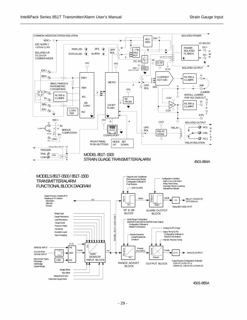
IntelliPack Series 851T Transmitter/Alarm User's Manual Strain Gauge Input
___________________________________________________________________________________________
- 29 -
4
2K
R
COM
IN-
SEN-
IN+
EXC+
EXC-
2K
+5V
3
MICRO
2
3
+5V REG
16V
AV
-0.7V
NC1
NO1
RTN
V+
DC-
DC+
TRIG
EXC-
IN-
SEN+
6.65K
R
EXC+
+5V
+5V
RJ11
+5V
OPTI ISOL
3
DIGI-POT
OPTI ISOL
ADJREG
FLTR
-0.3V
+14V
V I
CM1
JMP
OU TP U T
I+
RELAY
OPTI ISOL
IS OLA TE D INP UT
TRIGGER
HA LF IN+
IN+
JUMP E R
IN-
EXC SUPPLY+3.5V to 11.4V
IN2
A/DCONV
REF+
PWR LED Z/FS
+5V
INP UT P WR
+5V LDO
15VDC-DC
RELAY
FILTER &CLAMPS
FILTER &CLAMPS
OUTP UT P WR
FILTER &CLAMPS
ISOLATED UPTO 15V OF COMMON MODE
VEXC+
FRONT PANELPUSH-BUTTONS
1.235V REF
REF-
IN1
STATUS LED ALARM
4
EEPROM
REF
POWER -ISOLATEDFLYBACK
PW R
CONFIG PORT
CURRENTOUT DAC
COMMON-MODE EXCITATION ISOLATION
4501-884A
ISOLATED OUTPUT
JUMPER
ISOLATED OUTPUT
10-36V DC
ISOLATED POWER
RELAYDRIVE
BRIDGECOMPLETION
MODE SETUP DOWN
MODEL 851T-1500STRAIN GUAGE TRANSMITTER/ALARM
+14V
12K INTFLASH
SIMULTANEOUSRATIOMETRICCONVERSION
RELAY ISOLATION
INSTALL JUMPERFOR VOLTAGE OUT
PV
Co
un
ts
IN1
A / D
REF
PV
Pe
rce
nt
Percent
Alarm
D / A
IN2
PV
Ala
rm
SP & DB BLOCK
AlarmK1
MO
DE
L: 8
51
T-1
50
0 O
NL
Y
BRIDGE INPUT
Bridge Offset
PV
EXCITATIONSENSE INPUT
Counts PV
Counts
OUTPUT BLOCKRANGE ADJUST BLOCK
Counts Percent(0 to 100%)
Transfer Functions: Linear/Proportional Linearizer
On/Off
LIMIT ALARM
4501-885A
ANALOG OUTPUT
Input Sensor Types:Full-BridgeHalf-BridgeQuarter-Bridge
Tare Offset
1.235V
SENSORINPUT BLOCK
ON
/OF
F
ALARM OUTPUT BLOCK
Setpoints and Deadbands(Full Sensor Input Range)Configuration Software orPush Buttons
RELAY CONTACTSSPDT (Form C)
Sensitivity
Poisson's Ratio
Relay (851T-1500): SPDT
Measurement Gain
Instrument Gauge Factor
Output Ranges (Configuration Software) 0-10V DC or 0-5V DC or 0-20mA DC, 4-20 mA DC or 0-1mA DC
Input Averaging
Excitation Level Output Trim (Z & FS) Configuration Software or Module Push Buttons
Normal / Reverse Acting
Lead Resistance
Gauge Factor
Gauge Resistance
Analog OUTPUT type
Bridge Type
Digital Process Variable (PV)Reading on PC Monitor Microstrain Millivolts Percent
Configuration Variables: High or Low Limit Alarm Relay Alarm Delay Automatic Reset or Latching Failsafe/Non-Failsafe
MODELS 851T-0500 / 851T-1500TRANSMITTER/ALARMFUNCTIONAL BLOCK DIAGRAM
Wide Range Configuration (Zero/Full-Scale Input for Zero/Full-Scale Output) Configuration Software or Module Push Buttons

IntelliPack Series 851T Transmitter/Alarm User's Manual Strain Gauge Input
___________________________________________________________________________________________
- 30 -
(REFERRED TO AS REVERSE TYPE)
(6 CONDUCTOR)RJ11 PLUG
MODEL 5030-9139 PIN CONNECTOR (DB9S)MATES TO THE DB9PCONNECTOR AT THESERIAL PORT OF THEHOST COMPUTER.
3DINPSCLK
RSTCOM
DOUT+5V 1
2SERIES 8XXT
COMPUTER CONNECTIONS
654
CONFIGURATION
RUNNING WINDOWS 95 OR NTPERSONAL COMPUTER
SERIAL ADAPTERINTELLIPACK
SOFTWARE
ACROMAGPC RUNNING
ATTACH ADAPTER TO COM1 OR COM2 ON THE PC.COM PORTS ARE SOFTWARE CONFIGURED.
(6 CONDUCTOR)RJ11 JACK
RJ11 PLUG
TB3
10 TO 36VDC
ZERO/FS LED (YELLOW)
MODE SWITCH
RELAY LED (YELLOW)
STATUS LED (YELLOW)RUN/PWR LED (GREEN)
UP/RESET SWITCH
DOWN/RESET SWITCH
RLY
Z/FS
MODE
AcromagRUN
ST
POWER
+
TO INTELLIPACK CABLESERIAL PORT ADAPTERMODEL 5030-902
CABLE SCHEMATIC
(6 CONDUCTOR)
6 FOOT CABLE
INTELLIPACK
SET
CONFIGURATION PORT: FOR
SET SWITCH
MODULE CONFIGURATION (SEE USER'S MANUAL).R
TB2
456
3
MODULE21
4501-643A
IN-
IN-
IN-
2K
2K
IN+
IN+
Rlead
SEN-
SEN+
Rlead
IN-
EXC+
HALF
EXC+
IN+
EXC-
4-11V
HALF
2K
2K
EXC-
SEN-
SEN+
IN+
ActiveGage
Rlead
Rlead
IN+
IN-
IN-
SEN-
EXC-
SEN+
EXC+
TB2 Connections
Jumper
EXC-
IN+
ExternalWired Half-Bridge
JUMPER
InternalHalf-Bridge
TB1 Connections
Jumper
TB1 Connections
JUMPER
Add Jumper Wire BetweenTB2-1 (IN-) & TB2-2 (HALF)To Use Internal Half-Bridge.
EXC+
SEN+
SEN-
4501-887A
TB1 Connections
Note That The Internal Half-BridgeMay Be Jumpered To Either IN+Or IN-, According To DesiredBridge Output Polarity.
InternalHalf-Bridge
NOTE: You Must JumperEXC Terminals To SENTerminals As Shown.
DummyGage
ExternalWired Half-Bridge
A "Dummy" Strain Gauge ShouldBe Used To Complete The BridgeAnd Should Be Mounted NearThe Active Gauge To MinimizeUnwanted Temperature Effects.
The Internal Half-Bridge UsesTwo Precision 2.0K Ohm +/-0.1%Resistors With Low +/-10ppm/CTC & Ratio-Matched to +/-0.02%.
A Second Input Of The A/D Monitors TheThe Excitation Voltage Level And TheCorresponding A/D Reference.
CAUTION: The Internal Excitation SupplyMust Be Turned OFF Prior To ConnectingTo An External Excitation Supply.
High-Impedance Differential Input MakesInput Lead Resistance Insignificant.
Sense Leads Sample The Excitation Level At TheBridge And Form The Ratiometric A/D ConverterReference Voltage.
External Wired Full-BridgeUsing External Excitation
FULL-BRIDGE CONFIGURATIONUSING INTERNAL EXCITATION
FULL-BRIDGE CONFIGURATIONWITH EXTERNAL EXCITATION
Add Jumper Wire BetweenTB2-1 (IN-) & TB2-2 (HALF)To Use Internal Half-BridgeTo Complete ExternalHalf-Bridge (See Note).
NOTE: The HALF Jumper Is AlsoRequired To Properly Bias TheInput When Using A MillivoltageSource To Simulate A Bridge Signal.
TB2 Connections
TB1 Connections
QUARTER-BRIDGE COMPLETIONHALF-BRIDGE COMPLETION
External Wired Full-BridgeUsing Internal Excitation
Small Sense Lead Currents (Less Than 0.5mA)Make Sense Lead Resistance Insignificant.
Excitation Lead Currents (Up To 120mA) MustConsider Lead Resistance And CorrespondingDrop In Excitation Voltage At The Bridge.
851T-0500 / 851T-1500BRIDGE COMPLETIONCONNECTIONS
Note That The Internal Half-Bridge May Be Jumpered ToEither IN+ Or IN-, AccordingTo Desired Bridge Output Polarity.
The Internal Half-Bridge UsesTwo Precision 2.0K Ohm +/-0.1%Resistors With Low +/-10ppm/CTC & Ratio-Matched to +/-0.02%.

IntelliPack Series 851T Transmitter/Alarm User's Manual Strain Gauge Input
___________________________________________________________________________________________
- 31 -
s
IN+
IN+
L
45 44 42 41
IN-
IN-
6 .6 5 K
I
TB
4
12
CM
1
NC
1
15
CO
M
TR
IG
TB 2
TB
3
I +
23
IN+
V +
SW
24
RT
N
26
DC
+
+ +
TB
1
SE
N+
SE
N-
EX
C-
TB
2
36 34 33
CR
/B
31
N.O. LOA D
N.C. LOA D
R
CR
S E NS E -
S E NS E +
TB 4
HA LF
TB 2
E X C-
S E N-
S E N+
TB 1
N.C.
HA LF
R
M ODE
RUN
OUTP UT
46
R
TR IG G E R
43
O U TP U T
TB 3
12 TO 36V DC
E A RTHGROUND (Note 1)
CR /B
E X CITA TION -
B RIDGE +
B RIDGE -
E X CITA TION +E X C+
COM
JUMP E RIN+
IN-
INTE RNA LHA LF-B RIDGE
TB 2
SET
Z/FS
ST
RLY
TB 4
2K
2K
TB 1
11
NO
1
TB 4
IN+
IN-
13 1614
CO
M
Digital Input
IN-
CR
21 2522
C O MP
DCJM
P
DC
E A RTHGROUND (Note 1)
S W
S HUNTE NA B LE
N.O.
Acromag
OR
EX
C+
HA
LF
35 32
VO
LTAG
E O
UTPU
T J
UM
PER
POWER
TO B RIDGENC
NC
COM
TRIG TRIG
E X C-
E X C+
S hielded Cable
TE RMINA L B LOCK S
RE MOV A B LE
(S E E US E R'S MA NUA L).
CONFIGURA TION P ORT: FOR
UP /RE S E T S W ITCH
MODE S W ITCH
ZE RO/FULL-S CA LE R E LA Y
RE LA Y LE D (Y E LLOW )
GROUND (851T-1500)
CURRE NT
V OLTA GE
S HIE LDE D CA B LE
P W R
GROUND
Use 15-30V ForTRIG Voltage
TB 2
S HUNTRE S
NC
S ee Drawing 4501-646 forinterposing relay connections
S P DT CONTA CTS
COM
15-30V
TRIG
TRIG input is optically isolated andincludes a 6.65K series connectedresistor. TRIG is asserted for TRIGvoltages from 15-30V DC.
(P LUG-IN TY P E )
MODULE CONFIGURA TION
S E T S W ITCH
DOW N/RE S E T S W ITCH
LE D (Y E LLOW )
S E E RE LA Y & DIGITA LINP UT CONNE CTIONSA T LE FT
E A RTH
OUT LOA D
RelayConnections
OUT LOA D
ANALOG OUTPUT
4501-886A
(S ee B ridge Completion and S huntCalibration Connections at left)
S H U N T
E A RTH
HA LF may jumper to IN+or IN-, according to desiredpolarity of input signal.
RUN/P W R LE D (GRE E N)S TA TUS LE D (Y E LLOW )
A jumper is requiredbetween output I+ andJMP for voltage output.Remove this jumperfor current output.
PG 1 OF 2
A dd jumper for half or quarterbridge completion, or if usinga millivolt signal source. Note that quarter-bridgecompletion will require that a dummy gauge be locatednear the active gauge (notincluded). Refer to drawing4501-887.
BRIDGE COMPLETION (Input Connections B elow)
MODELS 851T-0500 AND 851T-1500
NOTE 2: B e sure to complete input connections prior to applying power or resetting the module.
NOTE 1: This ground connection is recommended for best results. However, ifsensors are inherently connected to ground, use caution and avoid making additionalground connections which could generate ground loops and measurement error.
B R ID G E IN P U T
RELAY CONNECTIONS
DIGITAL INPUT
ELECTRICAL CONNECTIONS
SHUNT CALIBRATION CONNECTIONS
W A RNING:For compliance to applicable safety and performance standards, the use ofshielded cable is recommended as shown. A dditionally, the application ofearth ground must be in place as shown in this drawing. Failure to adhere tosound wiring and grounding practices may compromise safety and performance. S afety guidelines may require that this device be housed in an approved metalenclosure or sub-system, particularly for applications with voltages greater thanor equal to 75V DC or 50V A C.
IN+ IN+
+
-
TB 2
E X C-
TB 1
NC
NC
TB 2
TB 1
IN+
E X C-
2K
IN+ 2K
IN+
IN-
E X C-
S E N-
IN+
S E N+
NC
NC
JUMP E R
JUMP E R
E X C-
IN+
IN-
E X C-
S E N-
IN+
S E N+
IN+
E X C-
IN+
2K
2K
TB 2
JUMP E R
JUMP E RTB 1
E X CITA TION -
B RIDGE +
IN+NC
IN-NC
TB 2
IN-
IN+
TB 1
JUMP E R
E X C+
S E N+
NC
IN-
HA LF
IN-
E X C+
HA LF
IN-
E X C+
LOAD CELL (4-WIRE)
NC
JUMP E R
E X C+
S E N+
HA LF
IN-
E X C+
IN-
HA LF
IN-
E X C+
JUMP E R
B RIDGE -
S E NS E +
E X CITA TION +
2K
2K
NC
S E N- S E N- S E NS E -
TB 2
TB 1
TB 2
TB 1
E X C-
E X C+
IN+
S E N-
S E N+S E N+
The internal Half-B ridge is ratiomatched to 0.02%
E A RTHGROUND (Note 1)
E A RTH GROUND( S ee Note 1)
The internal Half-B ridge is ratiomatched to 0.02%
E A RTHGROUND (Note 1)
mVSOURCE
MILLIVOLT INPUT
4501-886A
E A RTHGROUND (Note 1)
HA LF
S E N-
S E N+
IN-
HA LF
IN+
IN-
E X C-
E X C+
DUMMYGA UGE
NOTE : For 4-W ire Load Cellswithout sense leads, the internalE X CITA TION terminals MUS Tbe Jumpered to their adjacentS E NS E terminals.
E A RTH GROUND( S ee Note 1)
NOTE : The Half-B ridgeJumper Is Required To P roperly B ias The mVS ignal S ource. CA UTION: Failure ToInstall The Half-B ridgeJumper W ill Result InMeasurement E rror.
PG 2 OF 2
Millivolt Range Is S etB y The P roduct Of E xcitation and RatedOutput (mV /V ).
(US ING INTE RNA L E X CITA TION A ND B RIDGE COMP LE TION) (US ING INTE RNA L E X CITA TION A ND B RIDGE COMP LE TION)
NOTE 2: B e sure to complete input connections prior to applying power or resetting the module.
NOTE 1: This ground connection is recommended for best results. However, ifsensors are inherently connected to ground, use caution and avoid making additionalground connections which could generate ground loops and measurement error.
IMPORTANT - EXTERNAL EXCITATIONModule E xcitation Terminals MUS T be jumpered to theiradjacent sense terminals for sensors utilizing external excitation.
W A RNING: Y ou MUS T turn OFF the internal excitationsupply prior to connecting an external excitation supplyor damage to the unit may occur.
QUA RTE R B RIDGE HA LF B RIDGE
(US ING INTE RNA L E X CITA TION)
QUARTER-BRIDGE HALF-BRIDGE
E A RTH GROUND( S ee Note 1)
LOAD CELL (6-WIRE)
6-WIRE LOAD CELL 4-WIRE LOAD CELLNOTE : The Internal E X CITA TIONTerminals Must B e Jumpered ToTheir A djacent S E NS E Terminals.
A dd Jumper for Half-B ridgecompletion and if using amillivoltage signal sourceto drive the input.
A dd Jumper for Half-B ridgecompletion and if using amillivoltage signal sourceto drive the input.
Remove the HA LF jumper forsensors that already completetheir bridge external to the module.
FULL-BRIDGE
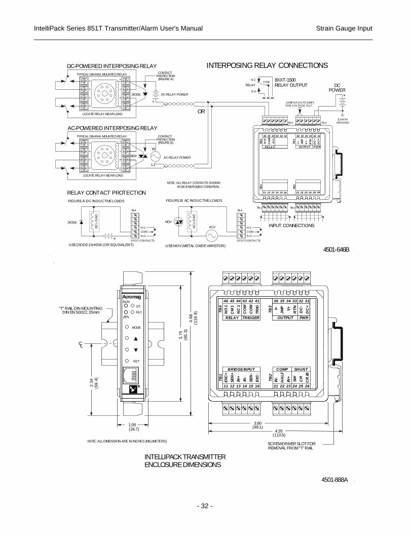
IntelliPack Series 851T Transmitter/Alarm User's Manual Strain Gauge Input
___________________________________________________________________________________________
- 32 -
DC-POWERED INTERPOSING RELAY INTERPOSING RELAY CONNECTIONS
(FIGURE A)PROTECTION
DC RELAY POWER
+
CONTACT
OR
IN DE-ENERGIZED CONDITION.
NOTE: ALL RELAY CONTACTS SHOWN
L1
AC RELAY POWER
W
PROTECTIONCONTACT
(FIGURE B)
TYPICAL DIN-RAIL MOUNTED RELAY
AC-POWERED INTERPOSING RELAY
TYPICAL DIN-RAIL MOUNTED RELAY
LOCATE RELAY NEAR LOAD
64
53
78
12
64
53
78
12
LOCATE RELAY NEAR LOAD
DIODE
MOV
DCPOWER
+
TB3
EARTHGROUND
313233
P W R
DC
DC
RELAYCOM
N.O.
N.C.
46
TB4
JUMPER [I+] TO [JMP]FOR VOLTAGE OUT
8XXT-1500RELAY OUTPUT
4445
45 44 43
N.C
.
CO
M
RE LAY
42 41
V +
RTN
TB
3
36 35 34
JM
P
I +
OUTP UT
TB
2
46
N.O
.
TB
4TB
1
TB4TB1
11
COM
N.C.
N.O.
SPDT CONTACTS
12 1413 15 16 21 22 23 24
TB2
INPUT CONNECTIONS
25 26
4501-646B
+
TB4
FIGURE A: DC INDUCTIVE LOADS
RELAY CONTACT PROTECTION
USE DIODE 1N4006 (OR EQUIVALENT)
DC
LO
AD
DIODE
SPDT CONTACTS
N.O.
N.C.
COM
FIGURE B: AC INDUCTIVE LOADS
MOV
USE MOV (METAL OXIDE VARISTOR)
ACVAC
LO
AD
C
R
SET
ST
IN+
IN-
IN+
SW
L
2.3
4
(95.3
)
TB
1T
B4
12
SE
N+
45
CM
1
13
44
NC
1
15
SE
N-
42
CO
M
16
EX
C-
41
TR
IG
TB
3
21
I+
36
23
V+
34
24
33
RT
N
26
CR
/B
31
DC
+
1.05
RLY
IN-
BRIDGE INPUT
(110.5)
COMP
CR
(59.4
)
(26.7)
MODE
RUN
Z/FS
Acromag
3.7
5
4.6
8
11 14
EX
C+
46 43
NO
1
CO
M
RELAY
4.35
22
TB
2
HA
LF
35
JM
P
OUTPUT
25
32D
C-
PWR
(118.9
)DIN EN 50022, 35mm
(99.1)
SHUNT
"T" RAIL DIN MOUNTING
3.90
TRIGGER
4501-888A
SCREWDRIVER SLOT FORNOTE: ALL DIMENSION ARE IN INCHES (MILLIMETERS)
REMOVAL FROM "T" RAIL
INTELLIPACK TRANSMITTERENCLOSURE DIMENSIONS

IntelliPack Series 851T Transmitter/Alarm User's Manual Strain Gauge Input
___________________________________________________________________________________________
- 33 -
Revision History
The following table details the revision history for this document:
Release Date Version EGR/DOC Description of Revision
3-AUG-2017 E CAP/JAA Remove CE Mark due to non-RoHS compliant part. Refer to ECN# 17G016.


![Sitecom WLM-4501 Full Manual English]](https://img.pdfslide.us/doc/110x75/53ff0b81dab5caed078b4695/sitecom-wlm-4501-full-manual-english.jpg)