Embed Size (px)
Citation preview
INTELLIGENT WELL COMPLETION 2013
IN
OIL AND GAS INDUSTRY
SUMITED TO
MS. M GOMTHI CE(PRODUCTION)
ONGC WELL SERVICES
BY
ABHIJEET KUMAR
BTECH (POLYMER SCIENCE & CHEMICAL TECH.)
DELHI TECHNOLOGICAL UNIVERSITY
TRAINEE AT ONGC FROM 15/7/13 TO 31/7/13
2INTELLIGENT WELL COMPLETION
INDEX
I. INTRODUCTIONII. GOALS OF IWC DEVELOPMENT
III. FUNCTIONAL ROLE OF INTELLIGRNT WELLIV. OBJECTIVE OF INTELLIGENT WELL FLOW CONTROLV. COMPONENTS OF IWC
CONVENTIONAL COMPONENTS WELL HEAD CHRISTMAS TREE (OIL-WELL) TUBING HANGER PRODUCTION TUBING DOWNHOLE SAFETY VALVE (DHSV) ANNULAR SAFETY VALVE SIDE POCKET MANDREL ELECTRICAL SUBMERSIBLE PUMP LANDING NIPPLE SLIDING SLEEVE PRODUCTION PACKER DOWNHOLE GAUGES PERFORATED JOINT FORMATION ISOLATION VALVE CENTRALIZER WIRELINE ENTRY GUIDE
VI. PERFORATING & STIMULATINGVII. INTERVENTION FREE COMPLETION
VIII. RESERVOIR ACCESSIX. TECHNICAL CHALLENGES OF IWCX. RISKS IN IWC
XI. RECENT DEVELOPMENT IN IWCXII. SAND CONTROL WITH INTELLIGENT WELLS
XIII. SOLUTIONS FOR SAND CONTROLXIV. CONCLUSION
INTRODUCTION
3INTELLIGENT WELL COMPLETION
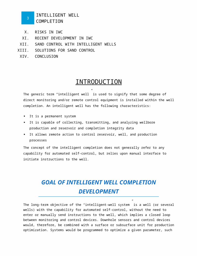
The generic term “intelligent well” is used to signify that some degree of direct monitoring and/or remote
control equipment is installed within the well completion. An intelligent well has the following
characteristics:
It is a permanent system
It is capable of collecting, transmitting, and analyzing wellbore production and reservoir and
completion integrity data
It allows remote action to control reservoir, well, and production processes
The concept of the intelligent completion does not generally refer to any capability for automated self-
control, but relies upon manual interface to initiate instructions to the well.
GOAL OF INTELLIGENT WELL COMPLETION DEVELOPMENT
The long-term objective of the “intelligent-well system” is a well (or several wells) with the capability for automated self-control, without the need to enter or manually send instructions to the well, which implies a closed loop between monitoring and control devices. Downhole sensors and control devices would, therefore, be combined with a surface or subsurface unit for production optimization. Systems would be programmed to optimize a given parameter, such as net production, by varying, for example, the inflow profile from various zones or perhaps the gas lift rate. This programming could be reset remotely. Recent and developing remote monitoring and control capabilities include: multiphase flow measurement; chemical composition and sand detection; multiple sensors and flow monitoring; remote-control gas-lift valves, flow-control sleeves, valves, and packers; along-hole profile detectors for pressure and distributed temperature; and seismic geophones and resistivity sensors.
FUNCTIONAL ROLE OF INTELLIGENT WELL
The intelligent well forms part of the overall vision of reservoir management optimization and automation system.
4INTELLIGENT WELL COMPLETION
Fine-tuning of production will no longer be limited to the surface processes.
Such wells will obviate or reduce the frequency of intervention required for reservoir and production monitoring and optimization.
Ultimate recovery and production will be increased by zonal/branch optimization and timely remedial work.
Gross fluid handling, waste, surface hardware costs (lines, separation, metering etc.), manpower and support services will be reduced.
Depending on access, the completion is either permanent or easily retrieved. In the former case, the intelligent well must therefore be rugged and reliable.
OBJECTIVE OF INTELLIGENT WELL FLOW CONTROL
The value of the intelligent-well technologies comes from the ability to actively modify the well zonal
completions and performance through flow control and to monitor the response and performance of the
zones through real-time downhole data acquisition, thereby maximizing the value of the asset. The oil/gas
industry has only begun to realize the potential of intelligent-well technology to contribute to efficiency and
productivity. Beyond the attraction of interventionless completions in the high-cost arena of subsea and
deepwater wells, intelligent-well technology can deliver improved hydrocarbon production and reserves
recovery with fewer wells. Intelligent-well technology can improve the efficiency of waterfloods and
gasfloods in heterogeneous or multilayered reservoirs when applied to injection wells, production wells, or
both. The production and reservoir data acquired with downhole sensors can improve the understanding
of reservoir behavior and assist in the appropriate selection of infill drilling locations and well designs.
Intelligent-well technology can enable a single well to do the job of several wells, whether through:
Controlled commingling of zones
Monitoring and control of multiple laterals
Allowing the well to take on multiple simultaneous functions
Injection well
5INTELLIGENT WELL COMPLETION
Observation well
Production well.
Finally, intelligent-well technology allows the operator to monitor aspects of wellbore mechanical
integrity or the environmental conditions under which the completion is operating and to modify the
operating conditions to maintain them within an acceptable integrity operating envelope.
COMPONENTS OF INTELLIGENT WELL COMPLETIONS
CONVENTIONAL COMPONENTS
Casing flow: means that the producing fluid flow has only one path to the surface through the casing.
Casing and tubing flow: means that the there is tubing within the casing that allows fluid to reach the
surface. This tubing can be used as a kill string for chemical injection. The tubing may have a “no-go”
nipple at the end as a means of pressure testing.
Pumping flow: the tubing and pump are run to a depth beneath the working fluid. The pump and rod
string are installed concentrically within the tubing. A tubing anchor prevents tubing movement while
pumping.
Tubing flow: a tubing string and a production packer are installed. The packer means that all the flow
goes through the tubing. Within the tubing you can mount a combination of tools that will help to
control fluid flow through the tubing.
Gas lift well: gas is fed into valves installed in mandrels in the tubing strip. The hydrostatic head is
lowered and the fluid is gas lifted to the surface.
Single-well alternate completions: in this instance there is a well with two zones. In order to produce
from both the zones are isolated with packers. Blast joints may be used on the tubing within the
region of the perforations. These are thick walled subs that can withstand the fluid abrasion from the
producing zone. This arrangement can also work if you have to produce from a higher zone given the
depletion of a lower zone. The tubing may also have flow control mechanism.
Single-well concentric kill string: within the well a small diameter concentric kill string is used to
circulate kill fluids when needed.
Single-well 2-tubing completion: in this instance 2 tubing strings are inserted down 1 well. They are
connected at the lower end by a circulating head. Chemicals can be circulated down one tube and
production can continue up the other.
2.WELL HEAD
6INTELLIGENT WELL COMPLETION
A wellhead is the component at the surface of an oil or gas well that provides the structural and pressure-containing interface for the drilling and production equipment.
The primary purpose of a wellhead is to provide the suspension point and pressure seals for the casing
strings that run from the bottom of the hole sections to the surface pressure control equipment.
While drilling the oil well, surface pressure control is provided by a blowout preventer (BOP). If the
pressure is not contained during drilling operations by the column of drilling fluid, casings, wellhead, and
BOP, a well blowout could occur.
Once the well has been drilled, it is completed to provide an interface with the reservoir rock and a tubular
conduit for the well fluids. The surface pressure control is provided by a Christmas tree, which is installed
on top of the wellhead, with isolation valves and choke equipment to control the flow of well fluids during
production.
Wellheads are typically welded onto the first string of casing, which has been cemented in place during
drilling operations, to form an integral structure of the well. In exploration wells that are later abandoned,
the wellhead may be recovered for refurbishment and re-use.
Offshore, where a wellhead is located on the production platform it is called a surface wellhead, and if
located beneath the water then it is referred to as a subseawellhead or mudline wellhead.
2.1.WELL HEAD FUNCTIONS
A wellhead serves numerous functions, some of which are:
1. Provide a means of casing suspension. (Casing is the permanently installed pipe used to line the
well hole for pressure containment and collapse prevention during the drilling phase).
2. Provides a means of tubing suspension. (Tubing is removable pipe installed in the well through
which well fluids pass).
3. Provides a means of pressure sealing and isolation between casing at surface when many casing
strings are used.
4. Provides pressure monitoring and pumping access to annuli between the different casing/tubing
strings.
5. Provides a means of attaching a blowout preventer during drilling.
6. Provides a means of attaching a Christmas tree for production operations.
7. Provides a reliable means of well access.
8. Provides a means of attaching a well pump,
3.CHRISTMAS TREE (OIL-WELL)
7INTELLIGENT WELL COMPLETION
Christmas trees are used on both surface and subsea wells. It is common to identify the type of tree as either "subsea tree" or "surface tree". Each of these classifications has a number of variations. Examples of subsea include conventional, dual bore, mono bore, TFL (through flow line), horizontal, mudline, mudline horizontal, side valve, and TBT (through-bore tree) trees. The deepest installed subsea tree is in the Gulf of Mexico at approximately 9,000 feet (2,700 m). (Current technical limits are up to around 3000 metres and working temperatures of -50°F to 350°F with a pressure of up to 15,000 psi.)
3.1.CHRISTMAS TREE FUNCTIONS
1.The primary function of a tree is to control the flow, usually oil or gas, out of the well. (A tree may also be used to control the injection of gas or water into a non-producing well in order to enhance production rates of oil from other wells.) When the well and facilities are ready to produce and receive oil or gas, tree valves are opened and the formation fluids are allowed to go through a flow line. This leads to a processing facility, storage depot and/or other pipeline eventually leading to a refinery or distribution center (for gas). Flow lines on subsea wells usually lead to a fixed or floating production platform or to a storage ship or barge, known as a floating storage offloading vessel (FSO), or floating processing unit (FPU), or floating production, storage and offloading vessel(FPSO).
2.A tree often provides numerous additional functions including chemical injection points, well intervention means, pressure relief means, monitoring points (such as pressure, temperature, corrosion, erosion, sand detection, flow rate, flow composition, valve and choke position feedback), and connection points for devices such as down hole pressure and temperature transducers (DHPT). On producing wells, chemicals or alcohols or oil distillates may be injected to preclude production problems (such as blockages). Functionality may be extended further by using the control system on a subsea tree to monitor, measure, and react to sensor outputs on the tree or even down the well bore. The control system attached to the tree controls the downhole safety valve (SCSSV, DHSV, SSSV) while the tree acts as an attachment and conduit means of the control system to the downhole safety valve.
Note that a tree and wellhead are separate pieces of
equipment not to be mistaken as the same piece. The Christmas tree is
installed on top of the wellhead. A wellhead is used without a Christmas tree during drilling operations, and also for riser tie-back situations that later would have a tree installed at riser top. Wells being produced with rod pumps (pump jacks, nodding donkeys, and so on) frequently do not utilize any tree owing to no pressure-containment requirement.
4.TUBING HANGER
A tubing hanger is a component used in the completion of oil and gas production wells. It is set in the tree or the wellhead and suspends the production tubing and/or casing. Sometimes it provides porting
8INTELLIGENT WELL COMPLETION
to allow the communication of hydraulic, electric and other downhole functions, as well as chemical injection. It also serves to seal-in the annulus and production areas.
5.PRODUCTION TUBING
Production tubing is a tube used in a wellbore through which production fluids are produced (travel).Production tubing is run into the drilled well after the casing is run and cemented in place. Production tubing protects wellbore casing from wear, tear, corrosion, and deposition of by-products, such as sand / silt, paraffins, and asphaltenes. Along with other components that constitute the production string, it provides a continuous bore from the production zone to the wellhead through which oil and gas can be produced. It is usually between five and ten centimeters in diameter and is held inside the casing through the use of expandable packing devices. Purpose and design of production tubing is to enable quick, efficient, and safe installation, removal and re-installation.
If there is more than one zone of production in the well, up to four lines of production tubing can be run.
6.DOWNHOLE SAFETY VALVE (DHSV) This component is intended as a last-resort method of protecting the surface from the uncontrolled
release of hydrocarbons. It is a cylindrical valve with either a ball or flapper closing mechanism. It is
installed in the production tubing and is held in the open position by a high-pressure hydraulic line from
surface contained in a 6.35 mm (1/4") control line that is attached to the DHSV's hydraulic chamber and
terminated at surface to an hydraulic actuator. The high pressure is needed to overcome the production
pressure in the tubing upstream of the choke on the tree. The valve will operate if the umbilical HP line is
cut or the wellhead/tree is destroyed.
This valve allows fluids to pass up or be pumped down the production tubing. When closed the DHSV
forms a barrier in the direction of hydrocarbon flow, but fluids can still be pumped down for well kill
operations. It is placed as far below the surface as is deemed safe from any possible surface disturbance
including cratering caused by the wipeout of the platform. Where hydrates are likely to form (most
production is at risk of this), the depth of the SCSSV (surface-controlled, sub-surface safety valve) below
the seabed may be as much as 1 km: this will allow for the geothermal temperature to be high enough to
prevent hydrates from blocking the valve.
7.ANNULAR SAFETY VALVE
9INTELLIGENT WELL COMPLETION
On wells with gas lift capability, many operators consider it prudent to install a valve, which will isolate
the A annulus for the same reasons a DHSV may be needed to isolate the production tubing in order to
prevent the inventory of natural gas downhole from becoming a hazard as it became on Piper Alpha.
8.SIDE POCKET MANDREL
This is a welded/machined product which contains a "side pocket" alongside the main tubular conduit.
The side pocket, typically 1" or 1½" diameter is designed to contain gas lift valve, which allows
hydrocarbon gas from the A annulus to be injected into the flow stream.
9.ELECTRICAL SUBMERSIBLE PUMP
This device is used for artificial lift to help provide energy to drive hydrocarbons to surface if reservoir
pressure is insufficient.
10.LANDING NIPPLE
A completion component fabricated as a short section of heavy wall tubular with a machined internal
surface that provides a seal area and a locking profile. Landing nipples are included in most completions
at predetermined intervals to enable the installation of flow-control devices, such as plugs and chokes.
Three basic types of landing nipple are commonly used: no-go nipples, selective-landing nipples and
ported or safety-valve nipples.
11.SLIDING SLEEVE
The sliding sleeve is hydraulically or mechanically actuated to allow communication between the tubing
and the 'A' annulus. They are often used in multiple reservoir wells to regulate flow to and from the zones.
12.PRODUCTION PACKER
The packer isolates the annulus between the tubing and the inner casing and the foot of the well. This is
to stop reservoir fluids from flowing up the full length of the casing and damaging it. It is generally placed
close to the foot of the tubing, shortly above the production zone.
13.DOWNHOLE GAUGES
10INTELLIGENT WELL COMPLETION
This is an electronic or fiberoptic sensor to provide continuous monitoring of downhole pressure and
temperature. Gauges either use a 1/4" control line clamped onto the outside of the tubing string to provide
an electrical or fiberoptic communication to surface, or transmit measured data to surface by acoustic
signal in the tubing wall.
14.PERFORATED JOINT
This is a length of tubing with holes punched into it. If used, it will normally be positioned below the packer
and will offer an alternative entry path for reservoir fluids into the tubing in case the shoe becomes
blocked, for example, by a stuck perforation gun.
15.FORMATION ISOLATION VALVE
This component, placed towards the foot of the completion string, is used to provide two way isolation
from the formation for completion operations without the need for kill weight fluids. Their use is sporadic
as they do not enjoy the best reputation for reliability when it comes to opening them at the end of the
completion process.
16.CENTRALIZER
In highly deviated wells, this components may be included towards the foot of the completion. It consists
of a large collar, which keeps the completion string centralised within the hole.
17.WIRELINE ENTRY GUIDE
This component is often installed at the end of the tubing, or "the shoe". It is intended to make pulling out
wireline tools easier by offering a guiding surface for the toolstring to re-enter the tubing without getting
caught on the side of the shoe.
11INTELLIGENT WELL COMPLETION
PERFORATING AND STIMULATING
In cased hole completions (the majority of wells), once the completion string is in place, the final stage is
to make a connection between the wellbore and the formation. This is done by running perforation guns to
blast holes in the casing or liner to make a connection. Modern perforations are made using shaped
explosive charges, similar to the armor-penetrating charge used on antitank rockets (bazookas).
Sometimes once the well is fully completed, further stimulation is necessary to achieve the planned
productivity. There are a number of stimulation techniques.
ACIDIZING
This involves the injection of chemicals to eat away at any skin damage, "cleaning up" the formation,
thereby improving the flow of reservoir fluids. A strong acid (usually HCl) is used to dissolve rock
formations, but this acid does not react with the Hydrocarbons. As a result the Hydrocarbons are more
accessible. Acid can also be used to clean the wellbore of some scales that form from mineral laden
produced water.
FRACTURING
This means creating and extending fractures from the perforation tunnels deeper into the formation,
increasing the surface area for formation fluids to flow into the well, as well as extending past any
possible damage near the wellbore. This may be done by injecting fluids at high pressure (hydraulic
fracturing), injecting fluids laced with round granular material (proppant fracturing), or using explosives to
generate a high pressure and high speed gas flow (TNT or PETN up to 1,900,000 psi (13,000,000 kPa) )
and (propellant stimulation up to 4,000 psi (28,000 kPa) ).
ACIDISING AND FRACTURING (COMBINED METHOD)
This involves use of explosives and injection of chemicals to increase acid-rock contact.
NITROGEN CIRCULATION
Sometimes, productivity may be hampered due to the residue of completion fluids, heavy brines, in the
wellbore. This is particularly a problem in gas wells. In these cases, coiled tubing may be used to
pumpnitrogen at high pressure into the bottom of the borehole to circulate out the brine.
12INTELLIGENT WELL COMPLETION
INTERVENTION FREE COMPLETION
Given the cost of higher capital expense, intelligent completions are designed for lifetime application, with overall materials selection being as important as the design of the more complex components. Not designing for retrieval can sometimes provide further opportunities to improve well integrity and reliability, for example by cemented annuli. However, given the current immature nature of many of the remote monitoring and control components, some form of recovery or intervention capability is prudent for the short to medium term.
Intelligent-completion installations are designed to fulfill specific operational requirements within severe environmental conditions. In particular, scaling of wellbores can adversely affect the performance of control devices. Careful monitoring of the performance of these devices is required to determine any degradation such that regular exercising can be completed to maintain full operability. Again, in these environments, some degree of capability for mechanical intervention may be advantageous to reinstate the operability of seized (because of scale) control devices.
RESERVOIR ACCESS
One faces a conflict between the concept of permanent remote control and the continuing perception (based on much experience) that a well must be designed for re-entry “just in case.” Emphasis on fluid rather than mechanical remedial treatments could minimize this conflict.
The following requirements are initially considered:
The system must enable manual override via conventional intervention and re-establishment of flow.
Components should be designed for the minimum pressure drop possible.
Injection treatments should be possible without removal of components.
Systems should withstand acid and scale treatments and not trap pockets of chemicals.
Through-wellbore access is preferable, even if it causes a reduced well diameter, unless components
are designed for easy removal and replacement (e.g., venturi flowmeter choke).
All components must be assessed for likely mineral scaling pattern and remedial or preventative
action (including stroking, magnets, and chemical treatments).
All components must be assessed for vulnerability to sand production.
13INTELLIGENT WELL COMPLETION
TECHNICAL CHALLENGES OF (IWC)
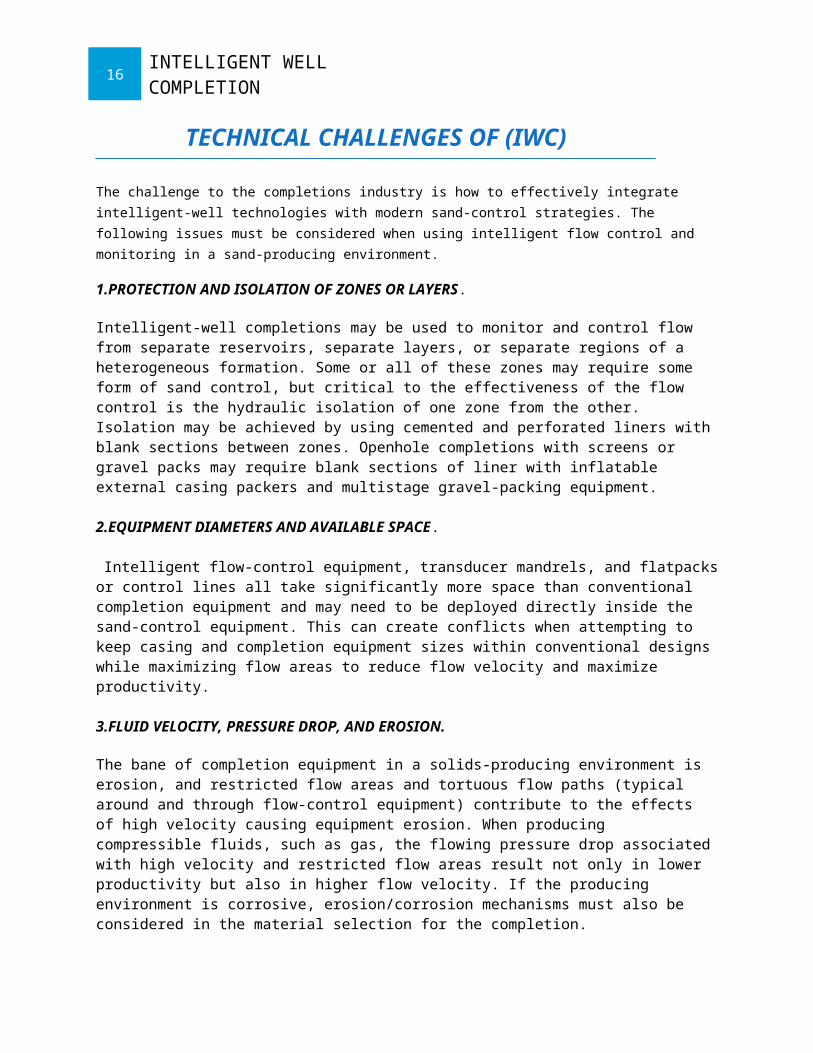
The challenge to the completions industry is how to effectively integrate intelligent-well technologies with modern sand-control strategies. The following issues must be considered when using intelligent flow control and monitoring in a sand-producing environment.
1.PROTECTION AND ISOLATION OF ZONES OR LAYERS.
Intelligent-well completions may be used to monitor and control flow from separate reservoirs, separate layers, or separate regions of a heterogeneous formation. Some or all of these zones may require some form of sand control, but critical to the effectiveness of the flow control is the hydraulic isolation of one zone from the other. Isolation may be achieved by using cemented and perforated liners with blank sections between zones. Openhole completions with screens or gravel packs may require blank sections of liner with inflatable external casing packers and multistage gravel-packing equipment.
2.EQUIPMENT DIAMETERS AND AVAILABLE SPACE.
Intelligent flow-control equipment, transducer mandrels, and flatpacks or control lines all take significantly more space than conventional completion equipment and may need to be deployed directly inside the sand-control equipment. This can create conflicts when attempting to keep casing and completion equipment sizes within conventional designs while maximizing flow areas to reduce flow velocity and maximize productivity.
3.FLUID VELOCITY, PRESSURE DROP, AND EROSION.
The bane of completion equipment in a solids-producing environment is erosion, and restricted flow areas and tortuous flow paths (typical around and through flow-control equipment) contribute to the effects of high velocity causing equipment erosion. When producing compressible fluids, such as gas, the flowing pressure drop associated with high velocity and restricted flow areas result not only in lower productivity but also in higher flow velocity. If the producing environment is corrosive, erosion/corrosion mechanisms must also be considered in the material selection for the completion.
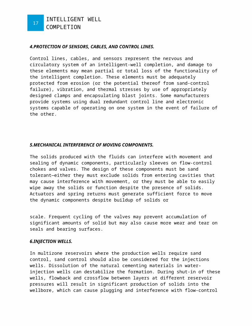
4.PROTECTION OF SENSORS, CABLES, AND CONTROL LINES.
Control lines, cables, and sensors represent the nervous and circulatory system of an intelligent-well completion, and damage to these elements may mean partial or total loss of the functionality of the intelligent completion. These elements must be adequately protected from erosion (or the potential thereof from sand-control failure), vibration, and thermal stresses by use of appropriately designed clamps and encapsulating blast joints. Some manufacturers provide systems using dual redundant control line and electronic systems capable of operating on one system in the event of failure of the other.
14INTELLIGENT WELL COMPLETION
5.MECHANICAL INTERFERENCE OF MOVING COMPONENTS.
The solids produced with the fluids can interfere with movement and sealing of dynamic components, particularly sleeves on flow-control chokes and valves. The design of these components must be sand tolerant—either they must exclude solids from entering cavities that may cause interference with movement, or they must be able to easily wipe away the solids or function despite the presence of solids. Actuators and spring returns must generate sufficient force to move the dynamic components despite buildup of solids or
scale. Frequent cycling of the valves may prevent accumulation of significant amounts of solid but may also cause more wear and tear on seals and bearing surfaces.
6.INJECTION WELLS.
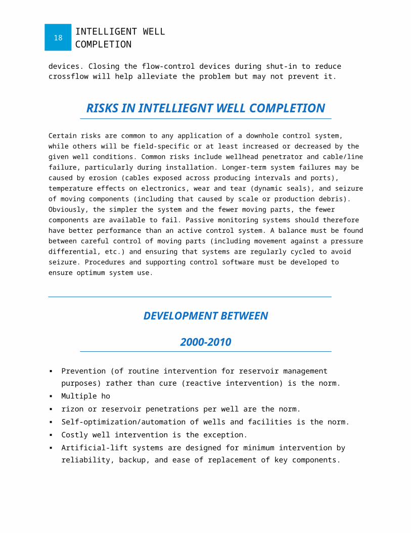
In multizone reservoirs where the production wells require sand control, sand control should also be considered for the injections wells. Dissolution of the natural cementing materials in water-injection wells can destabilize the formation. During shut-in of these wells, flowback and crossflow between layers at different reservoir pressures will result in significant production of solids into the wellbore, which can cause plugging and interference with flow-control devices. Closing the flow-control devices during shut-in to reduce crossflow will help alleviate the problem but may not prevent it.
RISKS IN INTELLIEGNT WELL COMPLETION
Certain risks are common to any application of a downhole control system, while others will be field-specific or at least increased or decreased by the given well conditions. Common risks include wellhead penetrator and cable/line failure, particularly during installation. Longer-term system failures may be caused by erosion (cables exposed across producing intervals and ports), temperature effects on electronics, wear and tear (dynamic seals), and seizure of moving components (including that caused by scale or production debris). Obviously, the simpler the system and the fewer moving parts, the fewer components are available to fail. Passive monitoring systems should therefore have better performance than an active control system. A balance must be found between careful control of moving parts (including movement against a pressure differential, etc.) and ensuring that systems are regularly cycled to avoid seizure. Procedures and supporting control software must be developed to ensure optimum system use.
15INTELLIGENT WELL COMPLETION
DEVELOPMENT BETWEEN
2000-2010
Prevention (of routine intervention for reservoir management purposes) rather than cure
(reactive intervention) is the norm.
Multiple ho
rizon or reservoir penetrations per well are the norm.
Self-optimization/automation of wells and facilities is the norm.
Costly well intervention is the exception.
Artificial-lift systems are designed for minimum intervention by reliability, backup, and ease
of replacement of key components.
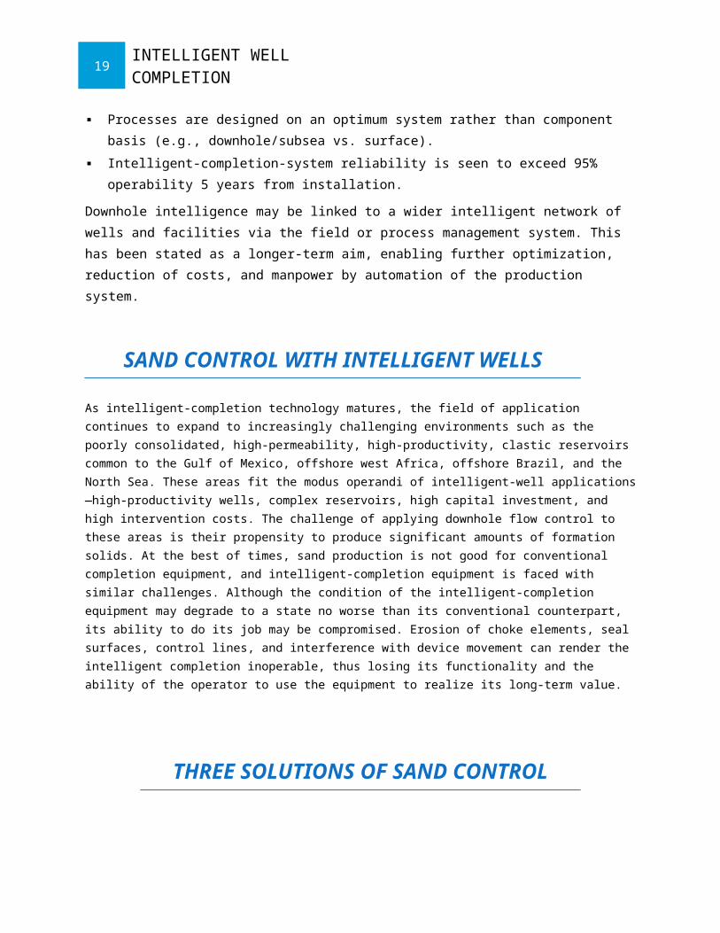
Processes are designed on an optimum system rather than component basis (e.g.,
downhole/subsea vs. surface).
Intelligent-completion-system reliability is seen to exceed 95% operability 5 years from
installation.
Downhole intelligence may be linked to a wider intelligent network of wells and facilities via the
field or process management system. This has been stated as a longer-term aim, enabling
further optimization, reduction of costs, and manpower by automation of the production system.
SAND CONTROL WITH INTELLIGENT WELLS
As intelligent-completion technology matures, the field of application continues to expand to increasingly challenging environments such as the poorly consolidated, high-permeability, high-productivity, clastic reservoirs common to the Gulf of Mexico, offshore west Africa, offshore Brazil, and the North Sea. These areas fit the modus operandi of intelligent-well applications—high-productivity wells, complex reservoirs, high capital investment, and high intervention costs. The challenge of applying downhole flow control to these areas is their propensity to produce significant amounts of formation solids. At the best of times, sand production is not good for conventional completion equipment, and intelligent-completion equipment is faced with similar challenges. Although the condition of the intelligent-completion equipment may degrade to a state no worse than its conventional counterpart, its ability to do its job may be compromised. Erosion of choke elements, seal surfaces, control lines, and interference with device movement can render the intelligent completion inoperable, thus losing its functionality and the ability of the operator to use the equipment to realize its long-term value.
16INTELLIGENT WELL COMPLETION
THREE SOLUTIONS OF SAND CONTROL
1.Use of intelligent-completion elements can significantly contribute to the management and prevention of sand production while maximizing hydrocarbon productivity. By monitoring actual inflow conditions and controlling and restricting fluid flow into the wellbore, intelligent wells can maintain the flow below critical rates that would otherwise destabilize the formation matrix or gravel pack. Zones that develop a propensity for water production can be choked back or closed in, also reducing the tendency for sand production aggravated by multiphase flow and aqueous dissolution of natural cements. One of the simplest solutions for controlling two zones with sand control is the dip tube or siphon tube solution.
2.A second solution for controlling multiple zones with sand control is done where each zone is completed with (from top down) a hydraulic set, hydraulic feed-through isolation packer, a gravel slurry placement sleeve, a shrouded ICV with the shroud attached to the gravel-pack screen base pipe and the ICV attached to an internal, concentric, through-wellbore, production conduit, which ties into the isolation packer of the next lower interval. The gravel-pack slurry is placed with coiled tubing or a small work string stung into the sand placement sleeve, which acts as a crossover device for flow from the coil to the casing annular area for gravel packing, with returns back up the coiled tubing/tubing annulus. This completion can also be run with screens only, without gravel packing.
3.A third and most promising solution is the use of intelligent-well equipment with expandable screens.[18] This solution maximizes flow areas in both the annulus and the production conduit. Installation of several dip-tube-type completions in the Gulf of Mexico has been successful. Two wells have been completed in the Allegheny field, while two other wells have been completed in the Typhoon field. One well in the King’s Peak field in the Gulf of Mexico was completed with a completion integrated with a multizone gravel pack. Additional similar completions are in the King’s Peak and the neighboring Aconcagua and Camden Hills fields. Five dip-tube-type intelligent completions have also successfully been installed in the Asia Pacific region. Of these completions, one combines a two-zone flow control system with a gravel-pack completion, and three are with expandable screen completions in the Champion West field. Those in the South Furious field use an internal gravel pack with an intelligent-completion expandable screen application.
17INTELLIGENT WELL COMPLETION
Conclusion
The oil and gas industry is climbing the learning curve rapidly toward recognizing the ultimate potential of intelligent-well technology—to contribute to efficiency and productivity. Beyond the attraction of interventionless completions in the high-cost arena of subsea and deepwater wells, intelligent-well technology has already demonstrated the ability to deliver improved hydrocarbon production and increased recovery with fewer wells. Intelligent-well technology can improve the efficiency of water floods and gas floods in heterogeneous or multilayered reservoirs when applied to injection wells, production wells, or both. Production and reservoir data acquired with downhole sensors can improve the understanding of reservoir behavior and assist in the appropriate selection of infill-drilling locations and well designs. Intelligent-well technology can leverage investment and enable a single well to do the job of several wells, whether through controlled commingling of zones, monitoring and control of multilaterals,or even allowing the well to take on multiple simultaneous functions (i.e., injection, observation, and production).
18INTELLIGENT WELL COMPLETION
WELL HEAD
CHRISTMAS TREE(OILWELL)
19INTELLIGENT WELL COMPLETION
20INTELLIGENT WELL COMPLETION
21INTELLIGENT WELL COMPLETION


![An intelligent system for taxi service: Analysis ... · An intelligent system for taxi service: Analysis, prediction and visualization ... [16] as well as the aggregation-based tech-niques](https://img.pdfslide.us/doc/110x75/5f37bd1913b3f370db0d5328/an-intelligent-system-for-taxi-service-analysis-an-intelligent-system-for-taxi.jpg)


![[XLS]reservoirengineering.org.ukreservoirengineering.org.uk/index/cms-filesystem-action... · Web viewSurveillance Notes Surveillance Abstract Intelligent well system technology enables](https://img.pdfslide.us/doc/110x75/5b1cbdae7f8b9a952f8b4730/xls-web-viewsurveillance-notes-surveillance-abstract-intelligent-well-system.jpg)