Embed Size (px)
Citation preview
Draft AIS-140/DF1/
May 2017
I
FINALIZED DRAFT
AUTOMOTIVE INDUSTRY STANDARD
Intelligent Transportation Systems (ITS)
- Requirements for Public Transport
Vehicle Operation
ARAI

Draft AIS-140/DF1/
May2017
II
CHECK LIST FOR PREPARING AUTOMOTIVE INDUSTRY STANDARD
AIS-140: Intelligent Transportation Systems (ITS) - Requirements for Public
Transport Vehicle Operation
Sl. No. PARTICULARS REMARKS
1. Indicate details of the base reference standard. (e.g. ECE / EEC
Directive/GTR etc.)
NA
2. Add an explanatory note indicating differences between the
above standard and the draft, if any.
NA
3.
Specify details of technical specifications to be submitted at the
time of type approval relevant to the requirements of this
standard covered.
Yes
4. Are the details of Worst Case Criteria covered? NA
5. Are the performance requirements covered? Yes
6. Is there a need to specify dimensional requirements? NA
7. If yes, are they covered?
8. Is there a need to specify COP requirements?
If yes, are they covered?
9.
Is there a need to specify type approval, and routine test
separately, as in the case of some of the Indian Standards?
If yes, are they covered?
NA
10.
If the standard is for a part/component or Sub-system;
i) AIS-037 or ISI marking scheme be implemented for this part?
ii) Are there any requirements to be covered for this part when
fitted on the vehicle?
If yes, has a separate standard been prepared?
NA
11.
If the standard is intended for replacing or revising an already
notified standard, are transitory provisions for re-certification of
already certified parts/vehicles by comparing the previous test
result, certain additional test, etc. required?
If yes, are they included?
NA
12. Include details of any other international or foreign national
standards which could be considered as alternate standard.
NA
13.
Are the details of accuracy and least counts of test
equipment/meters required to be specified?
If yes, have they been included?
Yes
14. What are the test equipment’s for establishing compliance? NA
15. If possible, identify such facilities available in India. ARAI,
iCAT
16.
Are there any points on which special comments or information
is to be invited from members?
If yes, are they identified?
NA
17. Does the scope of standard clearly identify vehicle categories? Yes
Draft AIS-140/DF/May 2017
III
Sl. No. PARTICULARS REMARKS
18. Has the clarity of definitions been examined? Yes
Status chart of the Standard to be used by the purchaser for updating the record
Sl.
No.
Corrigenda Amendment Revision Date Remark Misc.
General remarks:
Draft AIS-140/DF/May 2017
IV
INTRODUCTION
The Government of India felt the need for a permanent agency to expedite the
publication of standards and development of test facilities in parallel when the work
on the preparation of the standards is going on, as the development of improved
safety critical parts can be undertaken only after the publication of the standard and
commissioning of test facilities. To this end, the erstwhile Ministry of Surface
Transport (MoST) has constituted a permanent Automotive Industry Standards
Committee (AISC) vide order No. RT-11028/11/97-MVL dated September 15, 1997.
The standards prepared by AISC will be approved by the permanent CMVR
Technical Standing Committee (CTSC). After approval, the Automotive Research
Association of India (ARAI), Pune, being the secretariat of the AIS Committee, will
publish this standard.
Intelligent Transport Systems (ITS) are globally proven systems to optimize the
utilization of existing transport infrastructure and improve transportation systems in
terms of efficiency, quality, comfort and safety. Having realized the potential of ITS,
Government bodies and other organizations in India are presently working towards
implementing various components of ITS across the country.
The first step taken for creation and implementation of ITS was holding a National
Workshop titled “User Requirements for Interactive ITS Architecture”, which was
conducted as a collaboration between SIAM and ASRTU on 26th
& 27th
February
2015. This was primarily focused on ITS in Public Bus Transportation. Nonetheless,
the workshop helped to create the outline for “National Intelligent Transport System
Architecture and Policy for Public Transport (Bus)”, which was submitted by ASRTU
and SIAM to the government
In the 44th
& 45th
CMVR-TSC, Chairman had directed - standardization activities to
be initiated on Intelligent Transportation Systems (ITS) - Vehicle Location Tracking,
Camera Surveillance System and Emergency Request Button. The committee
intended to extend the above user requirements to all public transportation namely –
buses, taxis, etc. The current document covers the requirements for Vehicle Location
Tracking and Emergency Button. The other ITS components like PIS, CCTV system,
Fare collection etc. are deliberated and would be addressed in later phase and could
be added as separate parts to the current document..
Based on these directions, the AISC Panel on ITS has prepared this AIS-140 titled,
“Intelligent Transportation Systems (ITS) - Requirements for Public Transport
Vehicle Operation”
The panel has also deliberated and identified the necessary elements for an effective
implementation of vehicle level ITS system.
This standard has been prepared by considering inputs received from all stake holders
on ITS, mainly -

Draft AIS-140/DF/May 2017
V
a. Directions of CMVR-TSC
b. Detailed Specification Document on Vehicle Tracking Devices (dated 4th
March
2015, published by MoRTH)
c. Report of Department of Telecom (Telecom Engineering Centre) Automotive
Working Group on M2M enablement in Intelligent Transport System (ITS)
This AIS on ITS, has been provisioned for device level approval; including
construction and target vehicle level approval. Device level approval is needed to
enable retro-fitment of ITS systems on in-use vehicles. This will ensure ITS Backend
Control Centre infrastructure already presents with the STUs can be more fully
utilized and make the investment in the Backend Control Centre infrastructure more
viable.
As per the direction of CMVR-TSC which needed the Communication Protocol and
Backend Control Centre requirement for tracking and handling the alerts to be
detailed, the same has been addressed in Section 6 & 7, as detailed below.
The devices would transmit data to the Backend Control Centre using 2G/3G/4G
wireless connectivity (with SMS fall back) as per the protocol provided in
respective sections (Section 6).
The data from the devices would travel over the wireless telecom service provider
network and finally get delivered at the Backend Control Centre. The detail about
Device to Backend Communication Mechanism is mentioned in Section 7.
BIS and AIS both have panels which are formulating standards on ITS. It is our belief
that taking the AIS route for the 1st implementation would give the faster time for
adoption. Experts in the BIS panel and in DIMTS who are working on these subjects
have been co-opted and invited to work in the AIS panel to make the AIS as robust as
possible. Once implemented and all implementation problems in this emerging
technology have been eliminated, BIS standard can be made with further inclusions if
any resulting from consultations with the wider stakeholder community. Because of
these reasons, we recommend the AIS route for regulation creation and first
implementation.
One of the major concerns which has been raised during the panel meetings is on the
issue of privacy encroachments by ITS systems. Some overseas member countries of
the 1958 agreement have been continuously emphasizing in WP29 forums that the
regulated ITS system must not encroach on privacy. Towards this, the panel has
submitted a document titled ‘Data Privacy in Transportation ITS’ To help the system
developers deal with these issues. Further, system developer can also take guidance
from ‘IS/ISO/TR 12859: 2009 - Intelligent Transport Systems — System Architecture
— Privacy Aspects in ITS Standards and Systems’ while developing their systems to
meet the requirements of this standard. The Panel and the Automotive Industry
Standards Committee (AISC) responsible for preparation of this standard are given in
Annexure-D and Annexure -E respectively.

Draft AIS-140/DF/May 2017
VI
CONTENTS
Clause No. Details Page No.
1.0 Scope 1/40
2.0 Application For CMVR Type Approval 3/40
3.0 ITS Functions and Requirements 4/40
4.0 Communication Protocol 10/40
5.0 Construction and Installation 16/40
6.0 Functional, Performance, Durability, Environmental and
Protocol Tests 17/40
7.0 Device to Backend Communication Mechanism 31/40
List of Annexures
ANNEXURE-A Information to be Submitted for Type Approval 34/40
ANNEXURE-B Criteria for Extension of Type Approval 35/40
ANNEXURE-C Physical Interfaces (Connectors) for Power and I/Os 36/40
ANNEXURE-D Composition of Panel 38/40
ANNEXURE-E Committee Composition 40/40
Draft AIS-140/DF1/
May2017
1/40
Intelligent Transportation Systems (ITS) - Requirements for
Public Transport Vehicle Operation
1.0 SCOPE
1.A.0 This standard applies to both individual components as well as system
environment intended to be used in Public transport vehicles.
1.A.1 INTELLIGENT TRANSPORTATION SYSTEMS-VLT WITH AN
EMERGENCY SYSTEM
Requirements on ITS devices and functions - Vehicle Location Tracking
and Emergency Button
1.B.0 DEFINITIONS:
For the purpose of this standard, definitions are given below:
1.B.1 “Acquisition sensitivity” refers to the minimum signal level at which the
device is able to successfully perform a cold start TTFF. The acquisition
sensitivity test is a simulated signal test.
1.B.2 “Assisted GPS (A-GPS)” is a system allowing satellite receivers to obtain
information from communication network resources to assist in acquiring
satellite location. A-GPS system is especially useful when the receiver is in
a location where it is difficult for the satellite signals to penetrate. In
addition to providing better coverage, A-GPS also improves the start-up
time, which is the time required by the satellites and the receivers to
establish a reliable connection.
1.B.3 “Circular Error Probability (CEP)” is defined as the radius of a circle
centered on the true value that contains 50% of the actual GPS
measurements. So a receiver with 5 meter CEP accuracy will be within 5
meter of the true measurement 50% of the time. The other 50% of the time
the measurement will be in error by more than one meter.
1.B.4 “Dilution of Precision (DOP)” is the degree of proximity of the location
data to their mean value. The relative position of satellites affects the
accuracy of location calculation by the locating module. Location
coordinates computed when the satellites are clustered together suffer from
dilution of precision (DOP), a factor that multiplies the associated errors.
The DOP for an ideal satellites constellation arrangement equals close to 1,
which does not magnify the underlying errors.
1.B.5 “Distance Root Mean Square (DRMS also called RMS, 1Sigma)”
This is computed as square root of the average of the squared horizontal
position errors with 65% probability. The position expressed has the
probability of being within a circle with radius with 65% probability. A
locating module with 6 metre DRMS accuracy would be within 6 meters of
its actual position 65% of the time.

Draft AIS-140/DF/May 2017
2
1.B.6 “Emergency Button”A button provided in vehicle for passengers or crew
members to send specialized data packet /SMS to Centralized regulatory
server to indicate safety/panic situation caused by human or natural
disaster or vehicle accident etc.
1.B.7 “Global Positioning System (GPS)” is a space-based radio navigation
system. It provides positioning, navigation, and timing services to military
and civilian users on a continuous basis.
1.B.8 “Sensitivity “refers to the minimum signal strength level at which locating
module can successfully perform a location fix. A GNSS locating module
has two different sensitivity levels – acquisition sensitivity and tracking
sensitivity.
1.B.9 “Time to First Fix (TTFF)” describes the time required for a tracking
device to acquire adequate satellite signals and related data (almanac and
ephemeris data) to compute location.
1.B.10 “Tracking Sensitivity” refers to the minimum signal level at which the
device is able to successfully maintain the location fix. The acquisition
sensitivity test is a simulated signal test.
1.B.11 “Vehicle Location Tracking (VLT)”device uses satellite based location
technology to determine and record the precise location of a vehicle at
regular intervals. The location data so determined can be stored within the
device, and/or can be transmitted to the Backend Control Centre using a
wireless communication modem built in the device.
1.C REFERENCES:
The References are listed below.
1.C.1 National Level Vehicle Security and Tracking System – Detailed
Specification Document on Vehicle Tracking Devices (GPS) (Published by
MoRTH MoRTH).
1.C.2 APTA TCIP - American Public Transportation Association (APTA)
Standard for Transit Communications Interface Profiles (TCIP)
1.C.3 EBSF - European Bus System of the Future
1.C.4 ISO 11898-1:2003 Road vehicles — Controller area network (CAN)
1.C.5 SAE J 1939 Recommended Practice for a Serial Control and
Communications Vehicle Network.
1.C.6 Bus-FMS-Standard
1.C.7 SAE USCAR 18 / USCAR18-3 - FAKRA SMB RF CONNECTOR
SUPPLEMENT
1.C.8 National ITS Architecture - U.S. Department of Transportation
1.C.9 ISO 17185-1:2014 - Intelligent transport systems — Public transport user
information — Part 1: Standards framework for public information
Draft AIS-140/DF/May 2017
3
systems
1.C.10 Trans model Standard (CEN/TC 278 WG3/SG4, Reference Entity-
Relationship Data Model for Public Transport) - European reference data
model for Public Transport operations developed within several European
Projects - EN 12896:2006
1.C.11 Specification for Entity-Relationship for describing the main fixed objects
in Public transport CEN/TC 278, 2008 - EN 28701:2012
1.C.12 RTIG (Real Time Information Group Ltd) - Digital Air Interface Protocol
1.C.13 SIRI (Service Interface for Real Time Information) European Technical
Specification (TS) - CEN/TS 15531
1.C.14 NeTEx-Network Exchange European Technical Specification (TS)
CEN/TS 16614
1.C.15 NaPTAN (National Public Transport Access Node)
1.C.16 ISO 15638-15:2014 Intelligent transport systems – Framework for
cooperative telematics applications for regulated vehicles (TARV) – Part
15: Vehicle location monitoring
1.C.17 ISO 15638-5:2013 Intelligent transport systems – Framework for
collaborative Telematics Applications for Regulated commercial freight
Vehicles (TARV) – Part 5: Generic vehicle information
1.C.18 NMEA-0183: The NMEA 0183 standard defines an electrical interface and
data protocol for communications between marine instrumentation.
1.C.19 IS/ISO/TR 12859:2009 – Intelligent Transport System-System
Architecture-Privacy Aspects in ITS standards and systems
1.C.20 Report of Department of Telecom (Telecom Engineering Centre)
Automotive Working Group on M2M enablement in Intelligent Transport
System (ITS)
1.C.21 URL: http://tec.gov.in/pdf/M2M/M2M%20Enablement%20in%20ITS.pdf
2.0 APPLICATION FOR CMVR TYPE APPROVAL
2.1 The application for CMVR device level approval shall be accompanied by
information on the system specification as mentioned in Annexure A.
2.2 Type approval shall involve following steps:
2.2.1 Device Approval: Approval provided at Device level for compliance to
this standard.
These approved devices can be fitted / retro-fitted by manufacturer/ Dealer/
permit holder/system integrator in any vehicle model provided it shall meet
installation requirements as mentioned in Clause No. 5 of this standard.
For manufacturers seeking vehicle level approval with approved VLT with
Draft AIS-140/DF/May 2017
4
Emergency Buttons fitted shall only require installation approval as per the
provisions of Clause 5 and Sub-Clause 6.1 of Clause 6.
2.3 Modifications and Extension of Approval
2.3.1 Every modification pertaining to the information, even if the changes are
not technical in nature declared in accordance with clause 2.1, shall be
intimated by the VLT with Emergency Button Manufacturer / to the test
agency.
2.3.1.1 If the changes are in parameters not related to the provisions, no further
action need be taken.
2.3.1.2 If the changes are in parameters related to the provisions, the test agency,
which has issued the certificate of compliance, may then consider, based on
the justification provided by the VLT with Emergency Button Manufacturer
and reviewed by the test agency, whether,
The model with the changed specifications still complies with provisions;
Or,
Any further verification is required to establish compliance.
2.3.2 In case of 2.3.1.2, tests for only those parameters which are affected by the
modifications need be carried out based on Criteria for extension of type
approval as per Annexure B.
2.3.3 In case of fulfilment of criterion of clause 2.3.1.1 or after results of further
verification as per clause 2.3.1.2 are satisfactory, the approval of compliance
shall be extended for the changes carried out.
3.0 ITS FUNCTIONS AND REQUIREMENTS
The list of ITS functions envisaged from this device type is set out below
in Table 3A –
Table 3A: List of ITS Functions and Sub Functions
Function Sub Functions
Safety and Security
Emergency Buttons
Vehicle Location Tracking (VLT)
The above functions and their requirements shall be met by only single
device that can be interfaced by external emergency buttons. The
communications to Backend Control Server (Government authorized
server) shall be done by device as per the protocol and functionalities
defined below.
3.1 Vehicle Location Tracking (VLT) With Emergency Button
3.1.1 Functional Requirements for VLT
Draft AIS-140/DF/May 2017
5
3.1.1.1 Device shall be capable of obtaining position information using Global
Navigation Satellite System (GNSS). GNSS receiver specifications are as
follows:
a. Device shall be capable for operating in L and/or S band and include
support for NAVIC/IRNSS (Indian Regional Navigation Satellite
System) for devices installed on or after 1st April, 2018.
b. The Device shall support GAGAN, the Indian SBAS (Satellite Based
Augmentation System)
c. Device shall have a position accuracy of minimum 2.5 m CEP or 6 m
2DRMS
d. Device shall have an acquisition sensitivity of minimum (-) 148 dBm
e. Device shall have an tracking sensitivity of minimum (-) 165 dBm
f. Device shall have an internal antenna; however if in case of
Integrated systems with vehicle / aftermarket OEM approved kits if
the fitment location prevents the internal antenna from functioning,
then external antenna shall be provided.
3.1.1.2 Device shall support standard minimum I/Os as mentioned: 4 Digital, 2
Analogue and 1 Serial Communication (e.g. RS232) for interfacing
external systems (E.g. Digital input for Emergency request button
interfacing).
3.1.1.3 Device shall be capable of transmitting data to Backend Control Server
(Government authorized server) via Wide Area (Mobile)
Communications network (GSM/GPRS) as per Communication Protocol
in Section 4.
3.1.1.4 Device shall be capable of transmitting Position, Velocity and Time
(PVT data) along with heading (direction of travel) to a Backend Control
Server (Government authorized server) at configurable frequency as per
Communication Protocol of Section 4.
The fixed frequency shall be user configurable, minimum frequency shall
be 5 sec during vehicle operation and not less than 10 minutes in
sleep/IGN OFF) as per the protocol defined in Communication Protocol
of Section 4.
3.1.1.5 Device shall be capable of transmitting data to minimum 2 different IP
addresses (1 IP address for regulatory purpose (PVT data) and 1 IP
address for Emergency response system other than the IP’s required for
Operational purpose.
3.1.1.6 On pressing of Emergency button, the system implementing VLT
function shall send emergency Alert (Alert ID 10 as mentioned in Sub-
section 4.2.1 of Communication Protocol Section 4) to the configured IP
address(s) as per the Communication Protocol mentioned in Section 4. In
the absence of GPRS network, the emergency alert shall be sent as SMS
message along with vehicle location data to configured control center
number(s). The SMS shall consist parameters as given in Sub-section
4.2.2.
Draft AIS-140/DF/May 2017
6
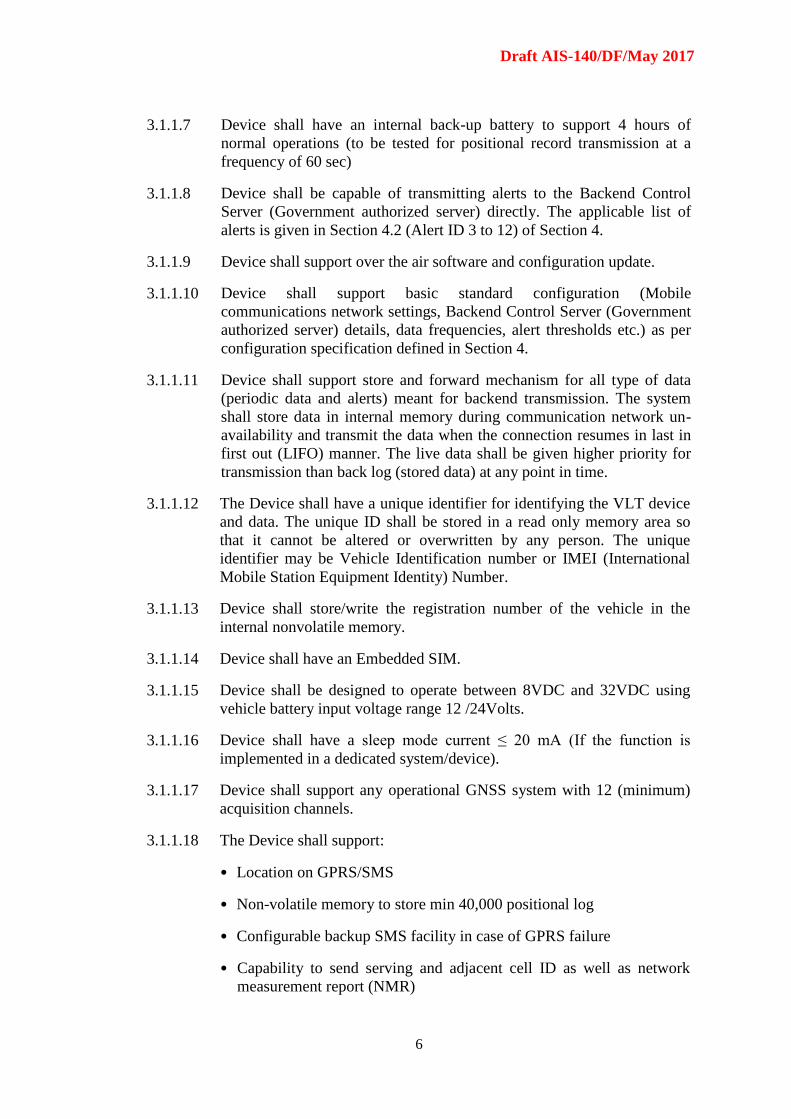
3.1.1.7 Device shall have an internal back-up battery to support 4 hours of
normal operations (to be tested for positional record transmission at a
frequency of 60 sec)
3.1.1.8 Device shall be capable of transmitting alerts to the Backend Control
Server (Government authorized server) directly. The applicable list of
alerts is given in Section 4.2 (Alert ID 3 to 12) of Section 4.
3.1.1.9 Device shall support over the air software and configuration update.
3.1.1.10 Device shall support basic standard configuration (Mobile
communications network settings, Backend Control Server (Government
authorized server) details, data frequencies, alert thresholds etc.) as per
configuration specification defined in Section 4.
3.1.1.11 Device shall support store and forward mechanism for all type of data
(periodic data and alerts) meant for backend transmission. The system
shall store data in internal memory during communication network un-
availability and transmit the data when the connection resumes in last in
first out (LIFO) manner. The live data shall be given higher priority for
transmission than back log (stored data) at any point in time.
3.1.1.12 The Device shall have a unique identifier for identifying the VLT device
and data. The unique ID shall be stored in a read only memory area so
that it cannot be altered or overwritten by any person. The unique
identifier may be Vehicle Identification number or IMEI (International
Mobile Station Equipment Identity) Number.
3.1.1.13 Device shall store/write the registration number of the vehicle in the
internal nonvolatile memory.
3.1.1.14 Device shall have an Embedded SIM.
3.1.1.15 Device shall be designed to operate between 8VDC and 32VDC using
vehicle battery input voltage range 12 /24Volts.
3.1.1.16 Device shall have a sleep mode current ≤ 20 mA (If the function is
implemented in a dedicated system/device).
3.1.1.17 Device shall support any operational GNSS system with 12 (minimum)
acquisition channels.
3.1.1.18 The Device shall support:
• Location on GPRS/SMS
• Non-volatile memory to store min 40,000 positional log
• Configurable backup SMS facility in case of GPRS failure
• Capability to send serving and adjacent cell ID as well as network
measurement report (NMR)
Draft AIS-140/DF/May 2017
7
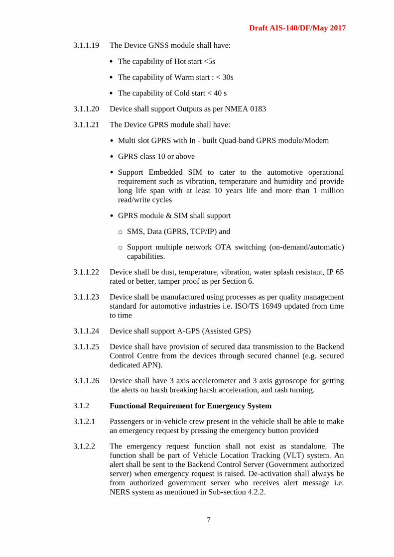
3.1.1.19 The Device GNSS module shall have:
• The capability of Hot start <5s
• The capability of Warm start : < 30s
• The capability of Cold start < 40 s
3.1.1.20 Device shall support Outputs as per NMEA 0183
3.1.1.21 The Device GPRS module shall have:
• Multi slot GPRS with In - built Quad-band GPRS module/Modem
• GPRS class 10 or above
• Support Embedded SIM to cater to the automotive operational
requirement such as vibration, temperature and humidity and provide
long life span with at least 10 years life and more than 1 million
read/write cycles
• GPRS module & SIM shall support
o SMS, Data (GPRS, TCP/IP) and
o Support multiple network OTA switching (on-demand/automatic)
capabilities.
3.1.1.22 Device shall be dust, temperature, vibration, water splash resistant, IP 65
rated or better, tamper proof as per Section 6.
3.1.1.23 Device shall be manufactured using processes as per quality management
standard for automotive industries i.e. ISO/TS 16949 updated from time
to time
3.1.1.24 Device shall support A-GPS (Assisted GPS)
3.1.1.25 Device shall have provision of secured data transmission to the Backend
Control Centre from the devices through secured channel (e.g. secured
dedicated APN).
3.1.1.26 Device shall have 3 axis accelerometer and 3 axis gyroscope for getting
the alerts on harsh breaking harsh acceleration, and rash turning.
3.1.2 Functional Requirement for Emergency System
3.1.2.1 Passengers or in-vehicle crew present in the vehicle shall be able to make
an emergency request by pressing the emergency button provided
3.1.2.2 The emergency request function shall not exist as standalone. The
function shall be part of Vehicle Location Tracking (VLT) system. An
alert shall be sent to the Backend Control Server (Government authorized
server) when emergency request is raised. De-activation shall always be
from authorized government server who receives alert message i.e.
NERS system as mentioned in Sub-section 4.2.2.
Draft AIS-140/DF/May 2017
8
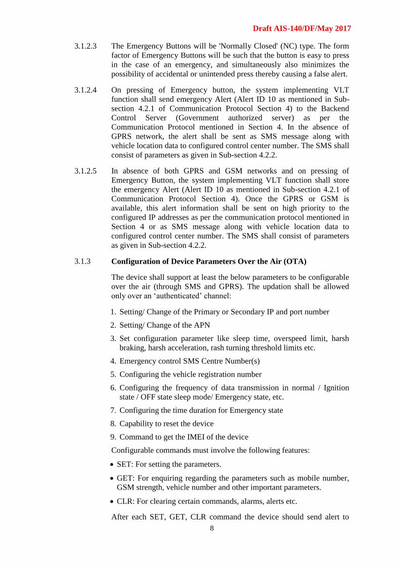
3.1.2.3 The Emergency Buttons will be 'Normally Closed' (NC) type. The form
factor of Emergency Buttons will be such that the button is easy to press
in the case of an emergency, and simultaneously also minimizes the
possibility of accidental or unintended press thereby causing a false alert.
3.1.2.4 On pressing of Emergency button, the system implementing VLT
function shall send emergency Alert (Alert ID 10 as mentioned in Sub-
section 4.2.1 of Communication Protocol Section 4) to the Backend
Control Server (Government authorized server) as per the
Communication Protocol mentioned in Section 4. In the absence of
GPRS network, the alert shall be sent as SMS message along with
vehicle location data to configured control center number. The SMS shall
consist of parameters as given in Sub-section 4.2.2.
3.1.2.5 In absence of both GPRS and GSM networks and on pressing of
Emergency Button, the system implementing VLT function shall store
the emergency Alert (Alert ID 10 as mentioned in Sub-section 4.2.1 of
Communication Protocol Section 4). Once the GPRS or GSM is
available, this alert information shall be sent on high priority to the
configured IP addresses as per the communication protocol mentioned in
Section 4 or as SMS message along with vehicle location data to
configured control center number. The SMS shall consist of parameters
as given in Sub-section 4.2.2.
3.1.3 Configuration of Device Parameters Over the Air (OTA)
The device shall support at least the below parameters to be configurable
over the air (through SMS and GPRS). The updation shall be allowed
only over an ‘authenticated’ channel:
1. Setting/ Change of the Primary or Secondary IP and port number
2. Setting/ Change of the APN
3. Set configuration parameter like sleep time, overspeed limit, harsh
braking, harsh acceleration, rash turning threshold limits etc.
4. Emergency control SMS Centre Number(s)
5. Configuring the vehicle registration number
6. Configuring the frequency of data transmission in normal / Ignition
state / OFF state sleep mode/ Emergency state, etc.
7. Configuring the time duration for Emergency state
8. Capability to reset the device
9. Command to get the IMEI of the device
Configurable commands must involve the following features:
SET: For setting the parameters.
GET: For enquiring regarding the parameters such as mobile number,
GSM strength, vehicle number and other important parameters.
CLR: For clearing certain commands, alarms, alerts etc.
After each SET, GET, CLR command the device should send alert to
Draft AIS-140/DF/May 2017
9
Backend Control Centre, as mentioned in Section 4 Alert 12, giving the
details of Mode, mobile no/ IP of control center sending commands.
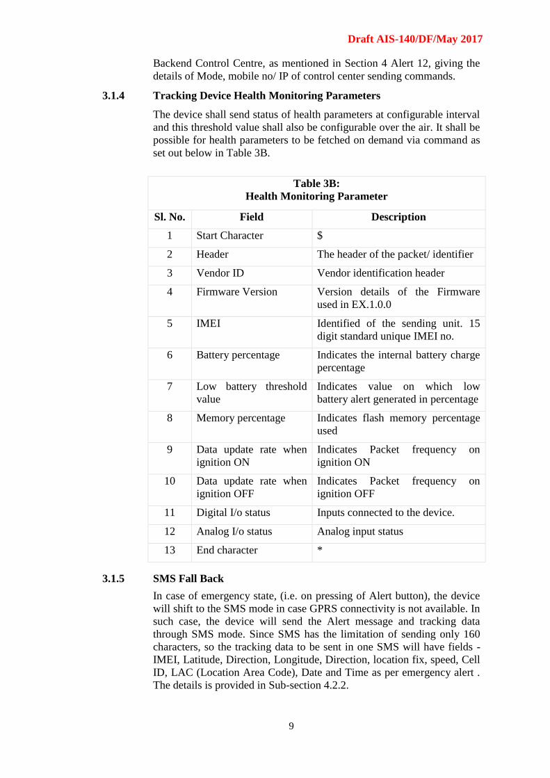
3.1.4 Tracking Device Health Monitoring Parameters
The device shall send status of health parameters at configurable interval
and this threshold value shall also be configurable over the air. It shall be
possible for health parameters to be fetched on demand via command as
set out below in Table 3B.
Table 3B:
Health Monitoring Parameter
Sl. No. Field Description
1 Start Character $
2 Header The header of the packet/ identifier
3 Vendor ID Vendor identification header
4 Firmware Version Version details of the Firmware
used in EX.1.0.0
5 IMEI Identified of the sending unit. 15
digit standard unique IMEI no.
6 Battery percentage Indicates the internal battery charge
percentage
7 Low battery threshold
value
Indicates value on which low
battery alert generated in percentage
8 Memory percentage Indicates flash memory percentage
used
9 Data update rate when
ignition ON
Indicates Packet frequency on
ignition ON
10 Data update rate when
ignition OFF
Indicates Packet frequency on
ignition OFF
11 Digital I/o status Inputs connected to the device.
12 Analog I/o status Analog input status
13 End character *
3.1.5 SMS Fall Back
In case of emergency state, (i.e. on pressing of Alert button), the device
will shift to the SMS mode in case GPRS connectivity is not available. In
such case, the device will send the Alert message and tracking data
through SMS mode. Since SMS has the limitation of sending only 160
characters, so the tracking data to be sent in one SMS will have fields -
IMEI, Latitude, Direction, Longitude, Direction, location fix, speed, Cell
ID, LAC (Location Area Code), Date and Time as per emergency alert .
The details is provided in Sub-section 4.2.2.
Draft AIS-140/DF/May 2017
10
4.0 COMMUNICATION PROTOCOL
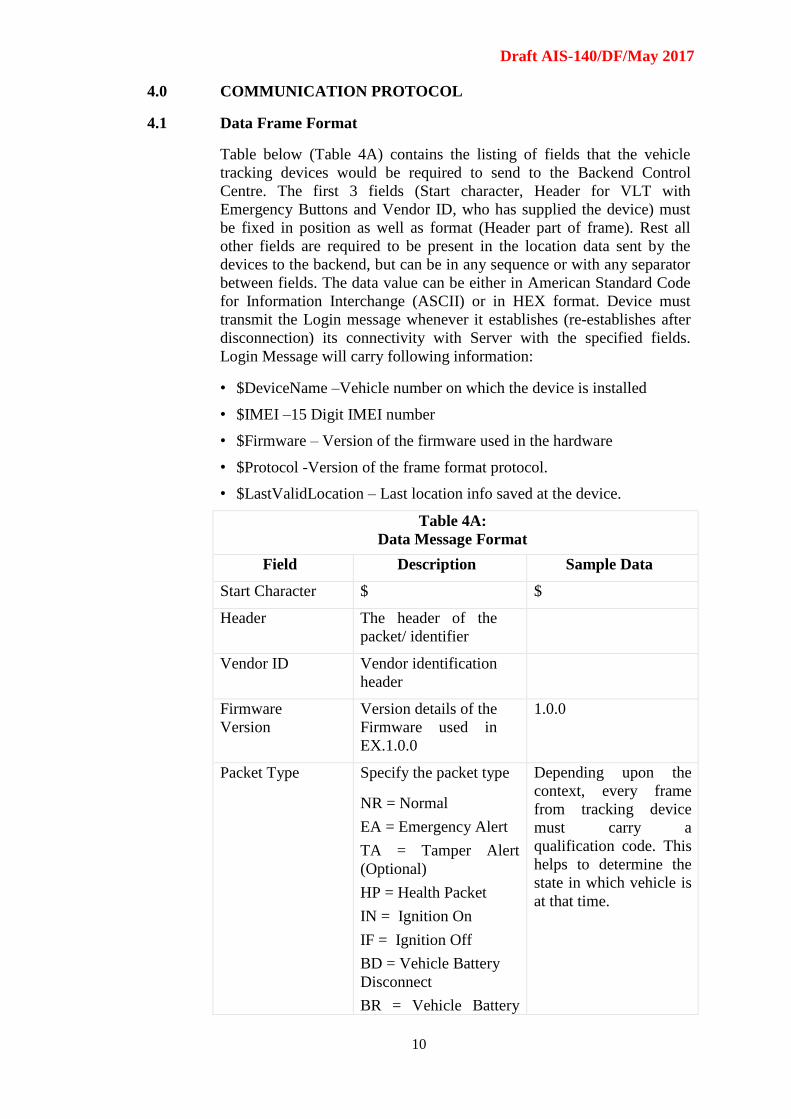
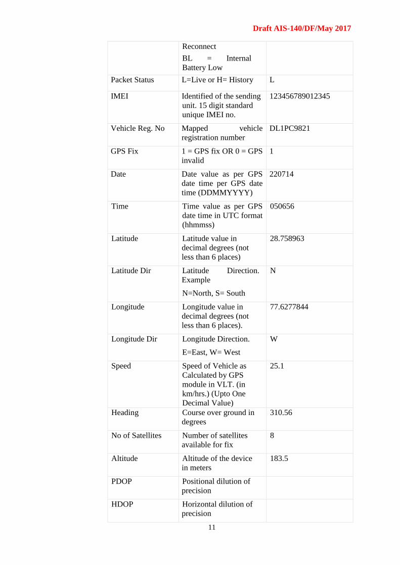
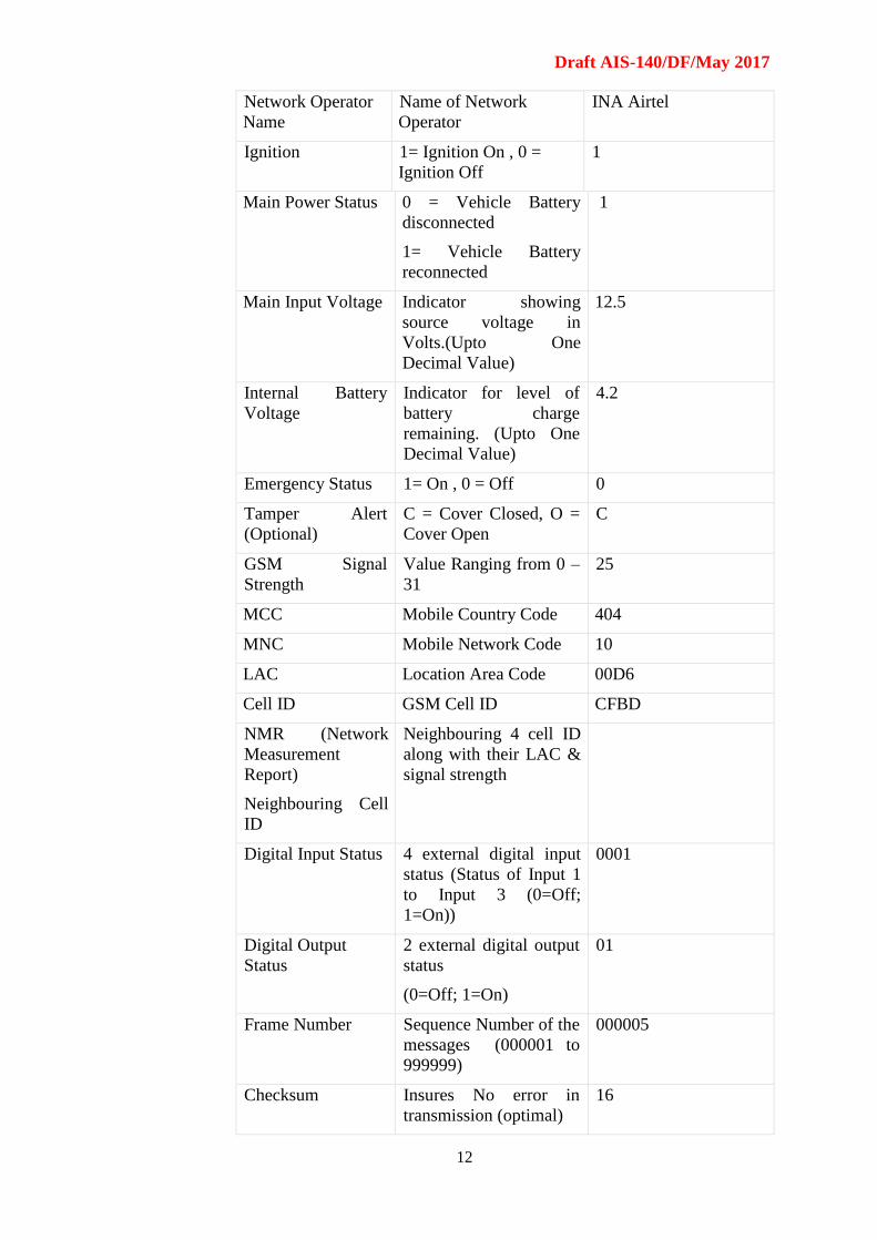
4.1 Data Frame Format
Table below (Table 4A) contains the listing of fields that the vehicle
tracking devices would be required to send to the Backend Control
Centre. The first 3 fields (Start character, Header for VLT with
Emergency Buttons and Vendor ID, who has supplied the device) must
be fixed in position as well as format (Header part of frame). Rest all
other fields are required to be present in the location data sent by the
devices to the backend, but can be in any sequence or with any separator
between fields. The data value can be either in American Standard Code
for Information Interchange (ASCII) or in HEX format. Device must
transmit the Login message whenever it establishes (re-establishes after
disconnection) its connectivity with Server with the specified fields.
Login Message will carry following information:
• $DeviceName –Vehicle number on which the device is installed
• $IMEI –15 Digit IMEI number
• $Firmware – Version of the firmware used in the hardware
• $Protocol -Version of the frame format protocol.
• $LastValidLocation – Last location info saved at the device.
Table 4A:
Data Message Format
Field Description Sample Data
Start Character $ $
Header The header of the
packet/ identifier
Vendor ID Vendor identification
header
Firmware
Version
Version details of the
Firmware used in
EX.1.0.0
1.0.0
Packet Type Specify the packet type
NR = Normal
EA = Emergency Alert
TA = Tamper Alert
(Optional)
HP = Health Packet
IN = Ignition On
IF = Ignition Off
BD = Vehicle Battery
Disconnect
BR = Vehicle Battery
Depending upon the
context, every frame
from tracking device
must carry a
qualification code. This
helps to determine the
state in which vehicle is
at that time.
Draft AIS-140/DF/May 2017
11
Reconnect
BL = Internal
Battery Low
Packet Status L=Live or H= History L
IMEI Identified of the sending
unit. 15 digit standard
unique IMEI no.
123456789012345
Vehicle Reg. No Mapped vehicle
registration number
DL1PC9821
GPS Fix 1 = GPS fix OR 0 = GPS
invalid
1
Date Date value as per GPS
date time per GPS date
time (DDMMYYYY)
220714
Time Time value as per GPS
date time in UTC format
(hhmmss)
050656
Latitude Latitude value in
decimal degrees (not
less than 6 places)
28.758963
Latitude Dir Latitude Direction.
Example
N=North, S= South
N
Longitude Longitude value in
decimal degrees (not
less than 6 places).
77.6277844
Longitude Dir Longitude Direction.
E=East, W= West
W
Speed Speed of Vehicle as
Calculated by GPS
module in VLT. (in
km/hrs.) (Upto One
Decimal Value)
25.1
Heading Course over ground in
degrees
310.56
No of Satellites Number of satellites
available for fix
8
Altitude Altitude of the device
in meters
183.5
PDOP Positional dilution of
precision
HDOP Horizontal dilution of
precision
Draft AIS-140/DF/May 2017
12
Network Operator
Name
Name of Network
Operator
INA Airtel
Ignition 1= Ignition On , 0 =
Ignition Off
1
Main Power Status 0 = Vehicle Battery
disconnected
1= Vehicle Battery
reconnected
1
Main Input Voltage Indicator showing
source voltage in
Volts.(Upto One
Decimal Value)
12.5
Internal Battery
Voltage
Indicator for level of
battery charge
remaining. (Upto One
Decimal Value)
4.2
Emergency Status 1= On , 0 = Off 0
Tamper Alert
(Optional)
C = Cover Closed, O =
Cover Open
C
GSM Signal
Strength
Value Ranging from 0 –
31
25
MCC Mobile Country Code 404
MNC Mobile Network Code 10
LAC Location Area Code 00D6
Cell ID GSM Cell ID CFBD
NMR (Network
Measurement
Report)
Neighbouring Cell
ID
Neighbouring 4 cell ID
along with their LAC &
signal strength
Digital Input Status 4 external digital input
status (Status of Input 1
to Input 3 (0=Off;
1=On))
0001
Digital Output
Status
2 external digital output
status
(0=Off; 1=On)
01
Frame Number Sequence Number of the
messages (000001 to
999999)
000005
Checksum Insures No error in
transmission (optimal)
16
Draft AIS-140/DF/May 2017
13
End Character Indicated End of the
frame
*
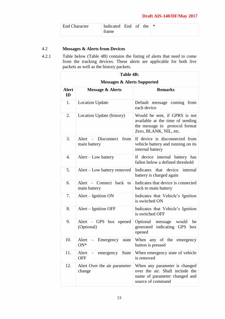
4.2 Messages & Alerts from Devices
4.2.1 Table below (Table 4B) contains the listing of alerts that need to come
from the tracking devices. These alerts are applicable for both live
packets as well as the history packets.
Table 4B:
Messages & Alerts Supported
Alert
ID
Message & Alerts Remarks
1. Location Update Default message coming from
each device
2. Location Update (history) Would be sent, if GPRS is not
available at the time of sending
the message in protocol format
Zero, BLANK, NIL, etc.
3. Alert – Disconnect from
main battery
If device is disconnected from
vehicle battery and running on its
internal battery
4. Alert – Low battery If device internal battery has
fallen below a defined threshold
5. Alert – Low battery removed Indicates that device internal
battery is charged again
6. Alert – Connect back to
main battery
Indicates that device is connected
back to main battery
7. Alert – Ignition ON Indicates that Vehicle’s Ignition
is switched ON
8. Alert – Ignition OFF Indicates that Vehicle’s Ignition
is switched OFF
9. Alert – GPS box opened
(Optional)
Optional message would be
generated indicating GPS box
opened
10. Alert – Emergency state
ON*
When any of the emergency
button is pressed
11. Alert – emergency State
OFF
When emergency state of vehicle
is removed
12. Alert Over the air parameter
change
When any parameter is changed
over the air. Shall include the
name of parameter changed and
source of command
Draft AIS-140/DF/May 2017
14
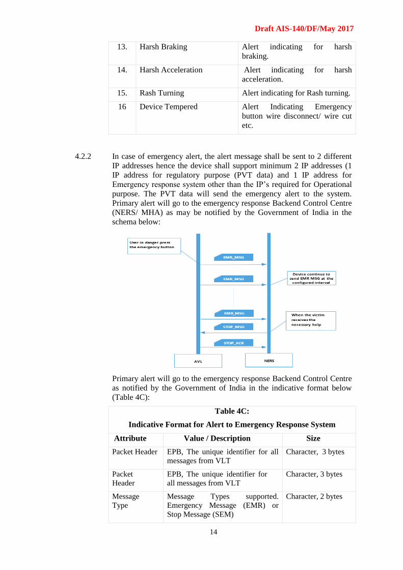
13. Harsh Braking Alert indicating for harsh
braking.
14. Harsh Acceleration Alert indicating for harsh
acceleration.
15. Rash Turning Alert indicating for Rash turning.
16 Device Tempered Alert Indicating Emergency
button wire disconnect/ wire cut
etc.
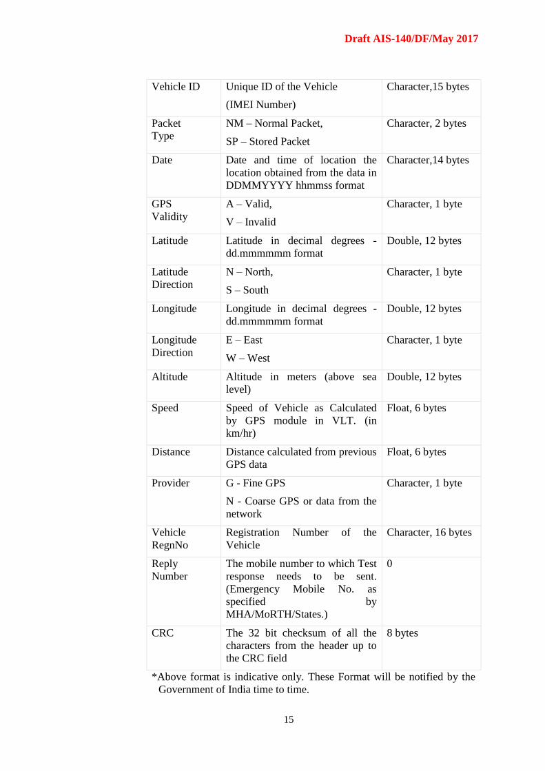
4.2.2 In case of emergency alert, the alert message shall be sent to 2 different
IP addresses hence the device shall support minimum 2 IP addresses (1
IP address for regulatory purpose (PVT data) and 1 IP address for
Emergency response system other than the IP’s required for Operational
purpose. The PVT data will send the emergency alert to the system.
Primary alert will go to the emergency response Backend Control Centre
(NERS/ MHA) as may be notified by the Government of India in the
schema below:
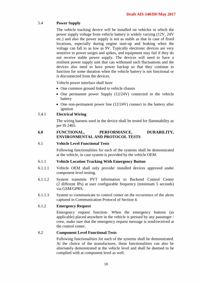
Primary alert will go to the emergency response Backend Control Centre
as notified by the Government of India in the indicative format below
(Table 4C):
Table 4C:
Indicative Format for Alert to Emergency Response System
Attribute Value / Description Size
Packet Header EPB, The unique identifier for all
messages from VLT
Character, 3 bytes
Packet
Header
EPB, The unique identifier for
all messages from VLT
Character, 3 bytes
Message
Type
Message Types supported.
Emergency Message (EMR) or
Stop Message (SEM)
Character, 2 bytes
Draft AIS-140/DF/May 2017
15
Vehicle ID Unique ID of the Vehicle
(IMEI Number)
Character,15 bytes
Packet
Type
NM – Normal Packet,
SP – Stored Packet
Character, 2 bytes
Date Date and time of location the
location obtained from the data in
DDMMYYYY hhmmss format
Character,14 bytes
GPS
Validity
A – Valid,
V – Invalid
Character, 1 byte
Latitude Latitude in decimal degrees -
dd.mmmmmm format
Double, 12 bytes
Latitude
Direction
N – North,
S – South
Character, 1 byte
Longitude Longitude in decimal degrees -
dd.mmmmmm format
Double, 12 bytes
Longitude
Direction
E – East
W – West
Character, 1 byte
Altitude Altitude in meters (above sea
level)
Double, 12 bytes
Speed Speed of Vehicle as Calculated
by GPS module in VLT. (in
km/hr)
Float, 6 bytes
Distance Distance calculated from previous
GPS data
Float, 6 bytes
Provider G - Fine GPS
N - Coarse GPS or data from the
network
Character, 1 byte
Vehicle
RegnNo
Registration Number of the
Vehicle
Character, 16 bytes
Reply
Number
The mobile number to which Test
response needs to be sent.
(Emergency Mobile No. as
specified by
MHA/MoRTH/States.)
0
CRC The 32 bit checksum of all the
characters from the header up to
the CRC field
8 bytes
*Above format is indicative only. These Format will be notified by the
Government of India time to time.

Draft AIS-140/DF/May 2017
16
4.3 Testing of Configuration of Device Parameters Over the Air (OTA)
The following testing will be done for
1. Setting/ Change of the Primary or Secondary IP and port number
2. Setting/ Change of the APN
3. Set configuration, parameter like sleep time for speed, harsh braking,
rash turns, etc.
4. Emergency SMS Centre Number
5. Configuring the vehicle registration number
6. Configuring the frequency of data transmission in normal / Ignition
state / OFF state sleep mode, Emergency state, etc.
7. Configuring the time duration for Emergency state
8. Capability to reset the device
9. Command to get the IMEI of the device
Configurable commands must involve the following features:
SET: For setting the parameters.
GET: For enquiring regarding the parameters such as mobile number,
GSM strength, vehicle number and other important parameters.
CLR: For clearing certain commands, alarms, alerts etc.
5.0 CONSTRUCTION AND INSTALLATION
(To be verified on component level and target vehicle level approval)
5.1 Requirements on vehicle interface for VLT with Emergency Button
Connector for Power
The requirements for interface shall be as below or as agreed between
vehicle manufacturer and device manufacturer.
Standard connectors conforming to ISO 15170 shall be used at vehicle
side. Connector requirements shall be as per Annexure – C, Clause 1.1
(Sl. No 1 - Low power systems 1)
However, Device/System side connector/s shall be pre-agreed with
equipment manufacturer by
Vehicle OEM in the case of OE fitment of the systems
System supplier in case of retro fitment in aftermarket.
These requirements do not apply to integrated systems with vehicle
where integration is done by vehicle manufacturer and /or System
Integrator.

Draft AIS-140/DF/May 2017
17
5.2 Requirement of Emergency System
Emergency button shall be one time press type. Separate release action
from authorized server shall be required to bring back the emergency
button to normal mode or clear emergency flag.
5.3 Physical Mounting
The VLT system shall be mounted in a suitable location such a way that
it is not easily accessible /exposed to passengers.
This requirement shall not be applicable in case of combined systems
VLT with HMI (Human Machine Interface) display in front of driver.
Test agency to verify this on vehicle level approval.
Emergency button(s) shall be fitted in such a way that every passenger
including driver shall be able to access the Emergency button(s).
Passenger Car shall have 2 emergency buttons on each passenger row
easily assessable by each of the passenger. There shall also be one
dedicated emergency button for the driver.
Passenger Transport bus shall have emergency buttons at locations easily
visible & assessable to all the passengers such as every 2 meters on both
the sides on passenger seating area. For seats reserved for ladies there
shall be a dedicated panic button for each row.
Test agency to verify this on vehicle level approval.
Draft AIS-140/DF/May 2017
18
5.4 Power Supply
The vehicle tracking device will be installed on vehicles in which the
power supply voltage from vehicle battery is widely varying (12V, 24V
etc.) and also the power supply is not as stable as that in case of fixed
locations, especially during engine start-up and braking when the
voltage can fall to as low as 9V. Typically electronic devices are very
sensitive to power surges and spikes, and equipment may fail if they do
not receive stable power supply. The devices will need to have a
resilient power supply unit that can withstand such fluctuations and the
devices also need to have power backup so that they continue to
function for some duration when the vehicle battery is not functional or
is disconnected from the devices.
Vehicle power interface shall have
One common ground linked to vehicle chassis
One permanent power Supply (12/24V) connected to the vehicle
battery
One non-permanent power line (12/24V) connect to the battery after
ignition
5.4.1 Electrical Wiring
The wiring harness used in the device shall be tested for flammability as
per IS 2465.
6.0 FUNCTIONAL, PERFORMANCE, DURABILITY,
ENVIRONMENTAL AND PROTOCOL TESTS
6.1 Vehicle Level Functional Tests
Following functionalities for each of the systems shall be demonstrated
at the vehicle, in case system is provided by the vehicle OEM.
6.1.1 Vehicle Location Tracking With Emergency Button
6.1.1.1 Vehicle OEM shall only provide/ installed devices approved under
component level testing.
6.1.1.2 System transmits PVT information to Backend Control Center
(2 different IPs) at user configurable frequency (minimum 5 seconds)
via GSM/GPRS.
6.1.1.3 System to communicate to control center on the occurrence of the alerts
captured in Communication Protocol of Section 4.
6.1.2 Emergency Request
Emergency request function- When the emergency buttons (as
applicable) placed anywhere in the vehicle is pressed by any passenger /
crew, make sure that the emergency request message is send/received at
the control center.
6.2 Component Level Functional Tests
Following functionalities for each of the systems shall be demonstrated.
At the choice of the manufacturer, these functionalities can also be
alternately demonstrated at the vehicle level and shall be deemed to be
complied with at component level as well.

Draft AIS-140/DF/May 2017
19
6.2.1 Vehicle Location Tracking
6.2.1.1 Standard connector provided for Power and other signals as per
Annexure C
6.2.1.2 Configuration of device as per the standard format mentioned in
Section 4.
Local configuration upload shall be verified
Configuration upload from control center shall be verified
6.2.1.3 Vehicle Location data transmission to Backend Control Center.
6.2.1.4 Backend Control Centre shall be able to check the version of firmware
loaded on the system.
6.2.1.5 Update the firmware of the system from Backend Control Centre
6.3 Device Level Functional, Performance & Durability Tests
The tests to be performed for device level approvals are as listed below.
These functionality check will be performed after each test as
acceptance criteria –
Tested systems shall satisfy general functional requirements at all the
specified ranges during the test and after the test.
Following to be checked after testing:
i) Tracking functionality shall be checked via Backend Control Centre
for the VLT system (Functional Test number 1 as per “Table 6A
Functional Testing”.
6.3.1 Functional Testing
Functional Testing as described in the Table 6A below shall be done
with the acceptance criteria in Table 6A after completion of all the
Performance & Durability Tests as listed in Table 6B.
Table 6A:
Functional Testing
Sl. No Test Test Procedure
1 Tracking
Functionality
Test
The test shall be conducted on VTL to
determine the proper functioning of VLT
with Emergency Button by testing its
connectivity to Backend Control Centre
(Government authorized server).
Procedure: The VLT with Emergency Button
shall be connected to vehicle battery to
switch it on. The VLT with Emergency
Button shall be tested for the connectivity to
server and its capability to send two location
messages

Draft AIS-140/DF/May 2017
20
2 Location
Accuracy Test
This test shall be conducted on VLT with
Emergency Button.
The receiver is placed into a cold start state –
usually by a command sent to the receiver
through a test connection – and then a fairly
strong navigation signal simulating in L
and/or S band is sent. The time it takes for
the receiver to determine its first good
location fix is recorded. Test is done many
times (>15 times) over many conditions and
the results are averaged.
Acceptance Criteria: 2.5 m CEP or 6 m
2DRMS
3 Acquisition
Sensitivity Test
This test shall be conducted on VLT with
Emergency Button.
Procedure: Set the simulator to output
navigation signal simulating L and/or S band
to a particular location with a very level so
that the tracking is not possible. Gradually
increase the signal level that allows the
receiver to successfully perform a cold start
TTFF within a specified time frame. The
minimum signal level that allows acquisition
is referred as to the acquisition sensitivity.
Acceptance Criteria: The acquisition
sensitivity shall be minimum (-) 148 dBm.
4 Tracking
Sensitivity Test
This test shall be conducted on VLT.
Procedure: The device under this test is
locked on to the simulator's output frequency
(navigation signal simulating L and/or S
band) and the simulator power output is
lowered until the lock is lost. Multiple
repetition of the test with different satellite
geometries ensures that an accurate average
measure is recorded.
Acceptance Criteria: The tracking
sensitivity shall be equal to or better than (-)
165 dBm.
Draft AIS-140/DF/May 2017
21
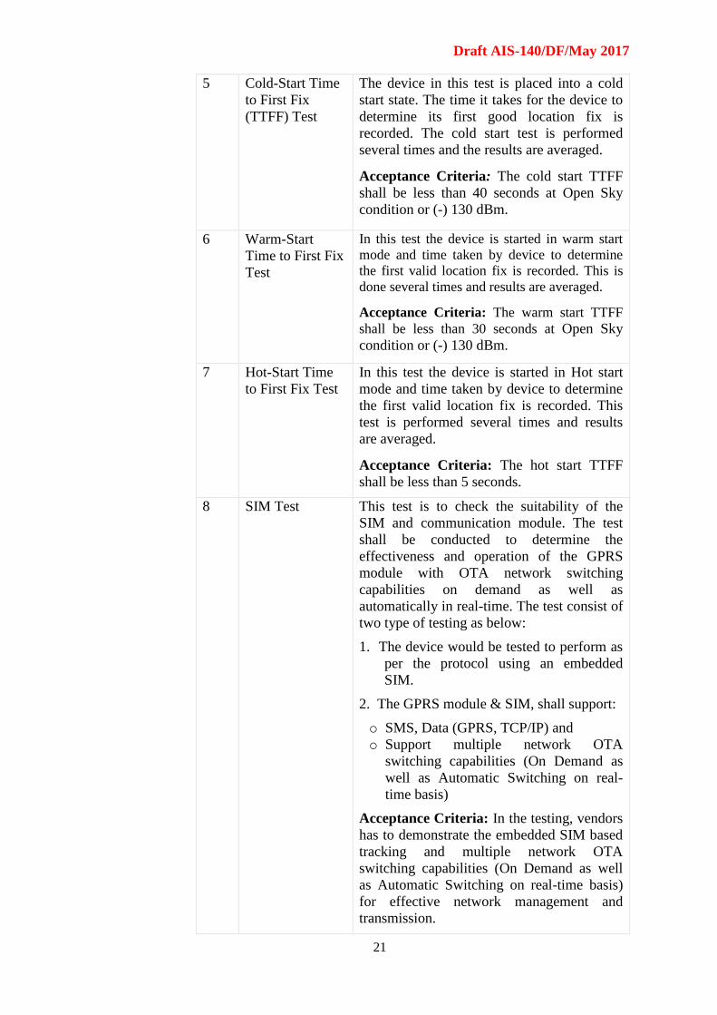
5 Cold-Start Time
to First Fix
(TTFF) Test
The device in this test is placed into a cold
start state. The time it takes for the device to
determine its first good location fix is
recorded. The cold start test is performed
several times and the results are averaged.
Acceptance Criteria: The cold start TTFF
shall be less than 40 seconds at Open Sky
condition or (-) 130 dBm.
6 Warm-Start
Time to First Fix
Test
In this test the device is started in warm start
mode and time taken by device to determine
the first valid location fix is recorded. This is
done several times and results are averaged.
Acceptance Criteria: The warm start TTFF
shall be less than 30 seconds at Open Sky
condition or (-) 130 dBm.
7 Hot-Start Time
to First Fix Test
In this test the device is started in Hot start
mode and time taken by device to determine
the first valid location fix is recorded. This
test is performed several times and results
are averaged.
Acceptance Criteria: The hot start TTFF
shall be less than 5 seconds.
8 SIM Test This test is to check the suitability of the
SIM and communication module. The test
shall be conducted to determine the
effectiveness and operation of the GPRS
module with OTA network switching
capabilities on demand as well as
automatically in real-time. The test consist of
two type of testing as below:
1. The device would be tested to perform as
per the protocol using an embedded
SIM.
2. The GPRS module & SIM, shall support:
o SMS, Data (GPRS, TCP/IP) and
o Support multiple network OTA
switching capabilities (On Demand as
well as Automatic Switching on real-
time basis)
Acceptance Criteria: In the testing, vendors
has to demonstrate the embedded SIM based
tracking and multiple network OTA
switching capabilities (On Demand as well
as Automatic Switching on real-time basis)
for effective network management and
transmission.

Draft AIS-140/DF/May 2017
22
9 Interference Test Interference testing is a type of test, in which
Cold Start/Hot Start test are performed with
device exposed to interfering signals and the
performance as recorded. In this test, the
GPS receiver is turned on and allowed to
achieve a location fix. The jamming signal is
then added to the GPS signal at a level that is
detectable to the GPS receiver. The jamming
signal power level is increased in 1 dB
increments until the first degradation of the
GPS receiver is noticed. This is typically a
dropped satellite. The jamming signal power
level is again slowly increased until the GPS
receiver loses its 3D navigation fix.
Acceptance Criteria: The Interference shall
not result in any degradation of the Cold
Start/Hot Start TTFF times. In addition, it
shall not result in any degradation of the
absolute location accuracy required and the
same shall be 2.5 m CEP or 6 m 2DRMS.
10 Multipath Test This test is a simulated frequency test
conducted to determine the effect of
multipath signals. The signal from a single
satellite is simulated to arrive at the device
via two or more paths. One path is typically a
direct path, and other paths are typically a
reflection of the same signal from building or
structure. Multipath testing is a kind of a
meta-test in that some of the above tests are
done with the addition of multi-path
simulation of one or more satellites by the
GPS signal simulator.
Acceptance Criteria: The multipath shall
not result in any degradation of the Cold
Start/Hot Start TTFF times. In addition, it
should not result in any degradation of the
absolute location accuracy required and the
same shall be 2.5 m CEP or 6 m 2DRMS.
6.3.2 Performance & Durability Test
The Performance & Durability Test is listed in Table 6B.
Table 6B:
Performance & Durability Test
Sl.
No Test Test Procedure
1 Shock Test Shock test is performed to provide a degree
of confidence that the device can physically
and functionally withstand the relatively

Draft AIS-140/DF/May 2017
23
infrequent, non-repetitive shocks
encountered in transportation environments.
This test provides an assessment of the effect
of the shocks on the performance of the
device. The test shall be performed as per IS
9000-part 7 – 2006. Severity Level = 15g,
Impact duration = 11ms, Impact Type = Half
sine, Total number of impact = 9 (3 on each
axis)
Acceptance Criteria: Device after the shock
test shall be required to meet the provisions
of Functional Test Number 1 as listed in
Table 6A.
2 Vibration Test This test is performed to check that the
device the device can physically and
functionally withstand the vibration
exposures in the life cycle typically
encountered in a vehicular environment. The
test shall be performed as per IS 9000-part 8
– 1981. The test specimen mounted on a
suitable support shall be rigidly fixed on a
suitable vibrating machine constructed to
produce simple harmonic function (total
amplitude of 1.5 mm) and shall be subjected
to vibration through a frequency range of 10-
55-10 Hz in a sweep period of 1 min with
continuously varying frequencies. The
vibration shall be applied for not less than 1
h in the directions of each of the 3 major axes
of the light.
Acceptance Criteria: During and after the test
the device shall be required to meet the
provisions of Functional Test Number 1 as
listed in Table 6A.
3 Ingress
Protection (IP)
The vehicle tracking devices must be able to
work in dusty environment that are typically
encountered by the public transport vehicles
where these would be installed. IP rating (IS/
IEC 60529 - 2001) is used for specifying the
environmental protection characteristics of the
tracking device. The device will be tested for
dust and water ingress according to IP 65
rating.
Acceptance Criteria: The device shall be
required to meet the provisions of Functional
Test Number 1 as listed in Table 6A.

Draft AIS-140/DF/May 2017
24
4 EMI /EMC The Electromagnetic Interference (EMI) and
Electromagnetic Compatibility (EMC) tests
are performed to assess whether the device
performs its intended functions in the
electromagnetic environment to which it
would be exposed. Further, the device shall
not generate electromagnetic disturbances
that may influence other equipment in the
vicinity.
Acceptance Criteria: The device shall meet
the EMI/EMC requirements as per AIS 004
(Part 3).
5 Battery Backup
Test
Battery backup is the amount of time that the
device battery can support sending the data
without being connected to the power source.
This test will be performed by disconnecting
the input charging voltage to the device. On
disconnecting the external supply, battery
would use its charge capacity to send data
through GPRS. Time duration between
external power disconnect to the last data
packet time denotes the battery backup time.
Acceptance Criteria: Device shall be able
to work in active mode for a period of 4
hours or more at the polling/ transmission
rate of 60 sec
6 Reverse Polarity
Protection
without Fuse
The device to be tested shall be connected to
a reversed voltage of 14 V for 12 V systems
and 27 V for 24 V systems for 2 min after
connecting the system to the suitable circuit.
Acceptance Criteria: After test; the device
shall be required to meet the provisions of
Functional Test Number 1 as listed in Table
6A
7 Wiring Harness -
Flammability
Test
Flammability Test: The wiring harness
used in the device shall be tested for
flammability as per IS 2465.
8 Wiring Harness -
Electrical
Properties
As per AIS 028
or DIN72551 or ISO 6722
9 Free Fall IS 9000 (Part VII/Sec 4) Free fall at 500 mm.
Acceptance Criteria: After test the device
shall be required to meet the provisions of
Functional Test Number 1 as listed in Table
A
Draft AIS-140/DF/May 2017
25
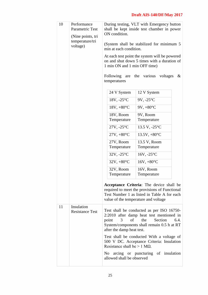
10 Performance
Parametric Test
(Nine points, tri
temperature/tri
voltage)
During testing, VLT with Emergency button
shall be kept inside test chamber in power
ON condition.
(System shall be stabilized for minimum 5
min at each condition.
At each test point the system will be powered
on and shut down 5 times with a duration of
1 min ON and 1 min OFF time)
Following are the various voltages &
temperatures
24 V System 12 V System
18V, -25°C 9V, -25°C
18V, +80°C 9V, +80°C
18V, Room
Temperature
9V, Room
Temperature
27V, -25°C 13.5 V, -25°C
27V, +80°C 13.5V, +80°C
27V, Room
Temperature
13.5 V, Room
Temperature
32V, -25°C 16V, -25°C
32V, +80°C 16V, +80°C
32V, Room
Temperature
16V, Room
Temperature
Acceptance Criteria: The device shall be
required to meet the provisions of Functional
Test Number 1 as listed in Table A for each
value of the temperature and voltage
11 Insulation
Resistance Test Test shall be conducted as per ISO 16750-
2:2010 after damp heat test mentioned in
point 3 of the Section 6.4.
System/components shall remain 0.5 h at RT
after the damp heat test.
Test shall be conducted With a voltage of
500 V DC. Acceptance Criteria: Insulation
Resistance shall be > 1 MΩ.
No arcing or puncturing of insulation
allowed shall be observed
Draft AIS-140/DF/May 2017
26
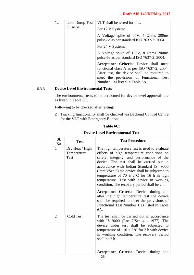
12 Load Dump Test
Pulse 5a
VLT shall be tested for this.
For 12 V System:
A Voltage spike of 65V, 4 Ohms 200ms
pulse-5a as per standard ISO 7637-2: 2004
For 24 V System:
A Voltage spike of 123V, 8 Ohms 200ms
pulse-5a as per standard ISO 7637-2: 2004.
Acceptance Criteria: Device shall meet
functional class A as per ISO 7637-2: 2004.
After test, the device shall be required to
meet the provisions of Functional Test
Number 1 as listed in Table 6A.
6.3.3 Device Level Environmental Tests
The environmental tests to be performed for device level approvals are
as listed in Table 6C.
Following to be checked after testing:
i) Tracking functionality shall be checked via Backend Control Centre
for the VLT with Emergency Button.
Table 6C:
Device Level Environmental Test
Sl.
No Test Test Procedure
1 Dry Heat / High
Temperature
Test
The high temperature test is used to evaluate
effects of high temperature conditions on
safety, integrity, and performance of the
device. The test shall be carried out in
accordance with Indian Standard IS: 9000
(Part 3/Sec 5) the device shall be subjected to
temperature of 70 ± 2°C for 16 h in high
temperature. Test with device in working
condition. The recovery period shall be 2 h.
Acceptance Criteria: Device during and
after the high temperature test the device
shall be required to meet the provisions of
Functional Test Number 1 as listed in Table
6A.
2 Cold Test The test shall be carried out in accordance
with IS 9000 (Part 2/Sec 4 - 1977). The
device under test shall be subjected to
temperature of –10 ± 2°C for 2 h with device
in working condition. The recovery period
shall be 2 h.
Acceptance Criteria: Device during and

Draft AIS-140/DF/May 2017
27
after the cold test, the device shall be
required to meet the provisions of Functional
Test Number 1 as listed in Table 6A.
3 Damp Heat Test The device under test shall be tested
according to IS 9000 (Part 5/Sec 2 - 1981).
The test is carried out at +25° to +55° C,
Humidity 95%. Six cycles (each test cycle of
24 h) shall be run with device in off
condition. Functional test shall be carried out
with power in ‘On condition’ at start of 2nd,
4th and 6th cycle.
Acceptance Criteria: Device during and
after the test the device shall be required to
meet the provisions of Functional Test
Number 1 as listed in Table 6A.
4 Temperature
Shock
Temperature shock test is carried out to
determine if the device can withstand sudden
changes in the temperature of the
surrounding atmosphere without
experiencing physical damage or
deterioration in performance. The device
shall be tested as per IS 9000 (Part 14/Sec 2)
– 1978. Exposure time would be 3
hours/cycle and number of cycles would be
two.
Acceptance Criteria: Device after the test
the device shall be required to meet the
provisions of Functional Test Number 1 as
listed in Table 6A.
5 High
Temperature
Test
The high temperature test is used to evaluate
effects of high temperature conditions on
safety, integrity, and performance of the
device. The test shall be carried out in
accordance with Indian Standard IS: 9000
(Part 3/Sec 5) the device shall be subjected to
temperature of 70 ± 2°C for 16 h in high
temperature. Test with device in working
condition. The recovery period shall be 2 h.
Acceptance Criteria: Device during and
after the high temperature test the device
shall be required to meet the provisions of
Functional Test Number 1 as listed in Table
6A.
6 Salt Spray
Test
The salt spray test is conducted to check
corrosion resistance of device. The device
shall be tested according to Clause 4.8 of IS
10250 for 96 h.
Acceptance Criteria: The device shall be
Draft AIS-140/DF/May 2017
28
required to meet the provisions of Functional
Test Number 1 as listed in Table 6A.
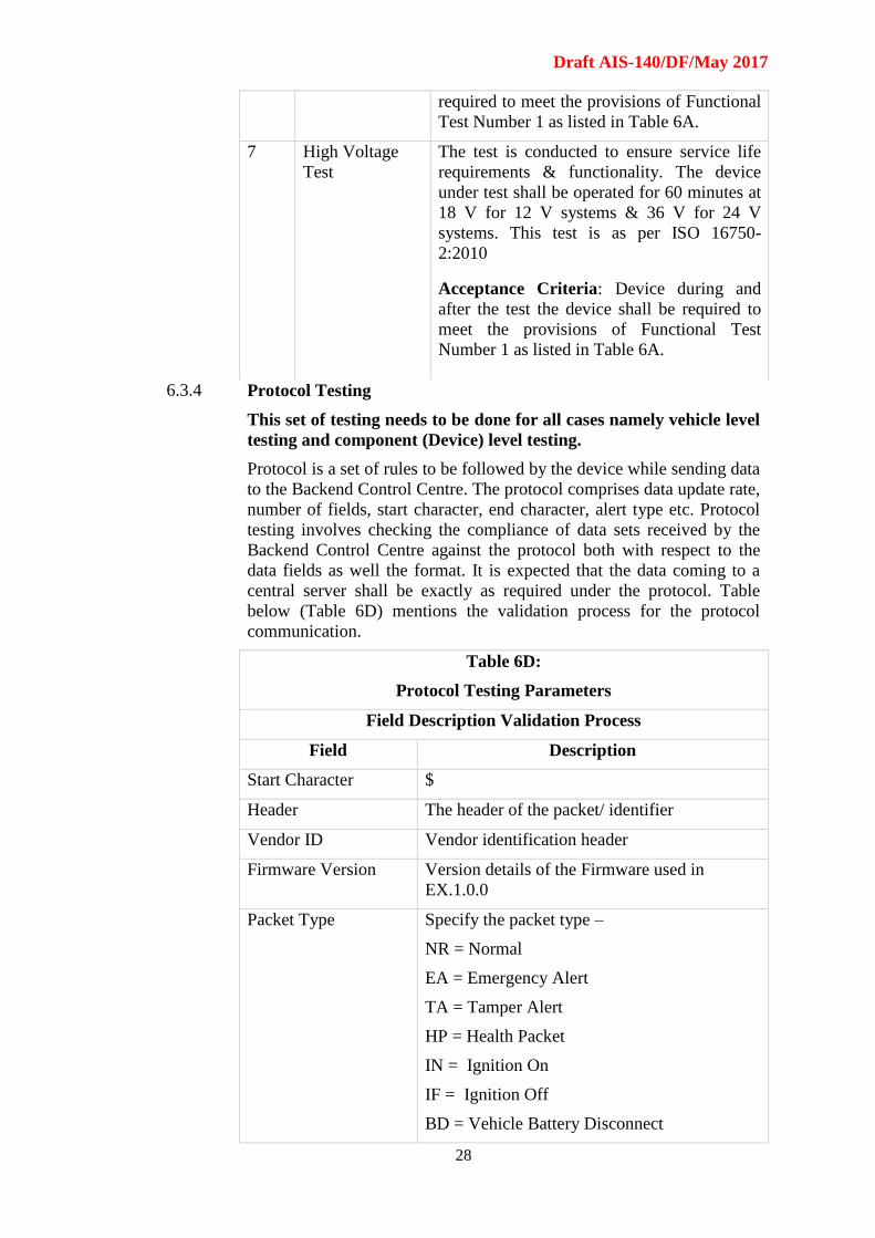
7 High Voltage
Test
The test is conducted to ensure service life
requirements & functionality. The device
under test shall be operated for 60 minutes at
18 V for 12 V systems & 36 V for 24 V
systems. This test is as per ISO 16750-
2:2010
Acceptance Criteria: Device during and
after the test the device shall be required to
meet the provisions of Functional Test
Number 1 as listed in Table 6A.
6.3.4 Protocol Testing
This set of testing needs to be done for all cases namely vehicle level
testing and component (Device) level testing.
Protocol is a set of rules to be followed by the device while sending data
to the Backend Control Centre. The protocol comprises data update rate,
number of fields, start character, end character, alert type etc. Protocol
testing involves checking the compliance of data sets received by the
Backend Control Centre against the protocol both with respect to the
data fields as well the format. It is expected that the data coming to a
central server shall be exactly as required under the protocol. Table
below (Table 6D) mentions the validation process for the protocol
communication.
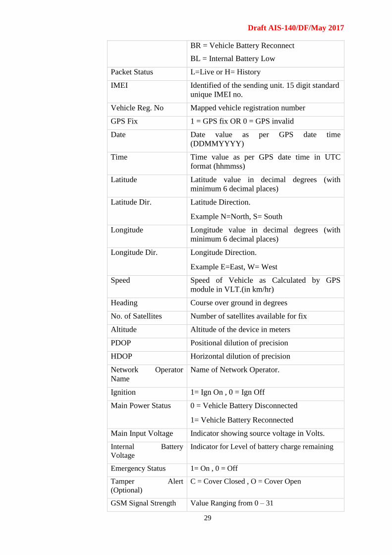
Table 6D:
Protocol Testing Parameters
Field Description Validation Process
Field Description
Start Character $
Header The header of the packet/ identifier
Vendor ID Vendor identification header
Firmware Version Version details of the Firmware used in
EX.1.0.0
Packet Type Specify the packet type –
NR = Normal
EA = Emergency Alert
TA = Tamper Alert
HP = Health Packet
IN = Ignition On
IF = Ignition Off
BD = Vehicle Battery Disconnect
Draft AIS-140/DF/May 2017
29
BR = Vehicle Battery Reconnect
BL = Internal Battery Low
Packet Status L=Live or H= History
IMEI Identified of the sending unit. 15 digit standard
unique IMEI no.
Vehicle Reg. No Mapped vehicle registration number
GPS Fix 1 = GPS fix OR 0 = GPS invalid
Date Date value as per GPS date time
(DDMMYYYY)
Time Time value as per GPS date time in UTC
format (hhmmss)
Latitude Latitude value in decimal degrees (with
minimum 6 decimal places)
Latitude Dir. Latitude Direction.
Example N=North, S= South
Longitude Longitude value in decimal degrees (with
minimum 6 decimal places)
Longitude Dir. Longitude Direction.
Example E=East, W= West
Speed Speed of Vehicle as Calculated by GPS
module in VLT.(in km/hr)
Heading Course over ground in degrees
No. of Satellites Number of satellites available for fix
Altitude Altitude of the device in meters
PDOP Positional dilution of precision
HDOP Horizontal dilution of precision
Network Operator
Name
Name of Network Operator.
Ignition 1= Ign On , 0 = Ign Off
Main Power Status 0 = Vehicle Battery Disconnected
1= Vehicle Battery Reconnected
Main Input Voltage Indicator showing source voltage in Volts.
Internal Battery
Voltage
Indicator for Level of battery charge remaining
Emergency Status 1= On , 0 = Off
Tamper Alert
(Optional)
C = Cover Closed , O = Cover Open
GSM Signal Strength Value Ranging from 0 – 31
Draft AIS-140/DF/May 2017
30
MCC Mobile Country Code
MNC Mobile Network Code
LAC Location Area Code
Cell ID GSM Cell ID
NMR (neighbouring
Cell ID)
Neighbouring 4 cell ID along with their LAC
and signal strength
Digital Input Status 4 external digital input status (Status of Input 1
to Input 3 (0=Off; 1=On))
Digital Output Status 2 external digital output status
(0=Off; 1=On)
Frame Number Sequence Number of the messages (000001 to
999999)
Checksum Insures No error in transmission (optional)
End Character Indicated End of the frame
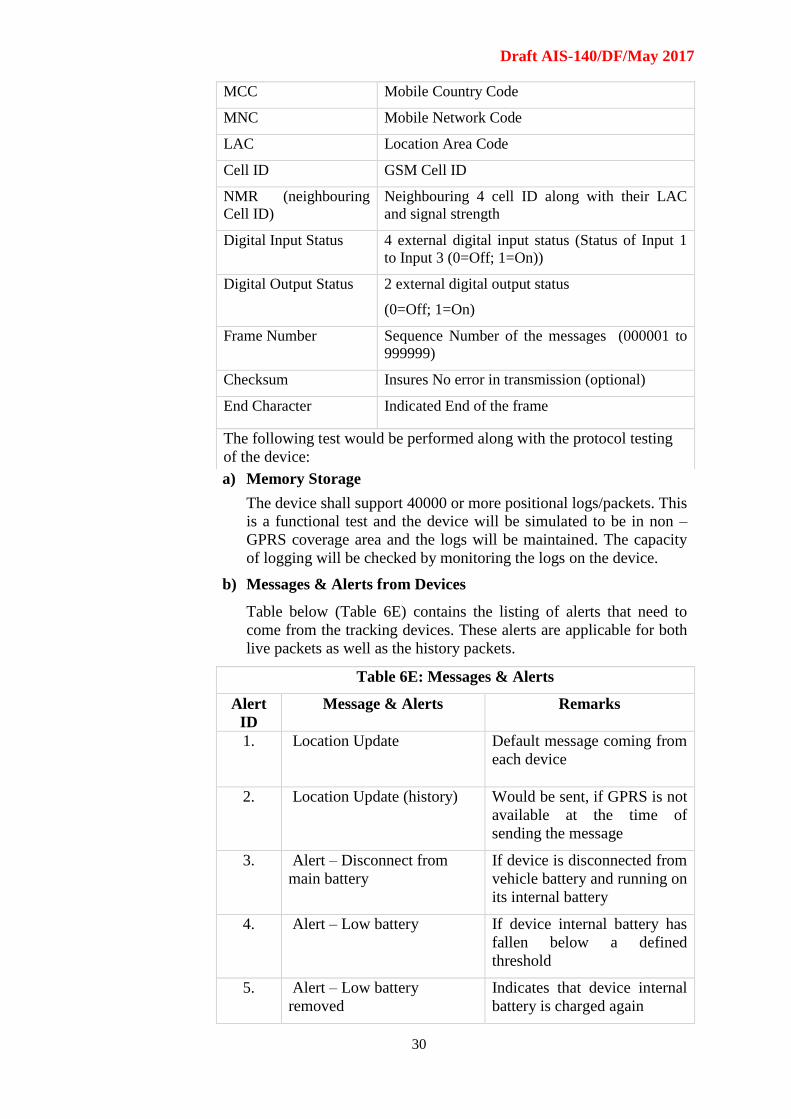
The following test would be performed along with the protocol testing
of the device:
a) Memory Storage
The device shall support 40000 or more positional logs/packets. This
is a functional test and the device will be simulated to be in non –
GPRS coverage area and the logs will be maintained. The capacity
of logging will be checked by monitoring the logs on the device.
b) Messages & Alerts from Devices
Table below (Table 6E) contains the listing of alerts that need to
come from the tracking devices. These alerts are applicable for both
live packets as well as the history packets.
Table 6E: Messages & Alerts
Alert
ID
Message & Alerts Remarks
1. Location Update Default message coming from
each device
2. Location Update (history) Would be sent, if GPRS is not
available at the time of
sending the message
3. Alert – Disconnect from
main battery
If device is disconnected from
vehicle battery and running on
its internal battery
4. Alert – Low battery If device internal battery has
fallen below a defined
threshold
5. Alert – Low battery
removed
Indicates that device internal
battery is charged again
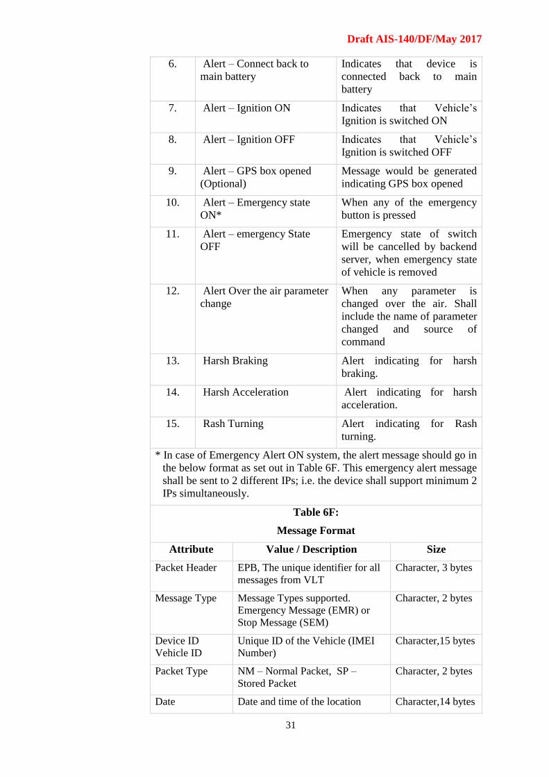
Draft AIS-140/DF/May 2017
31
6. Alert – Connect back to
main battery
Indicates that device is
connected back to main
battery
7. Alert – Ignition ON Indicates that Vehicle’s
Ignition is switched ON
8. Alert – Ignition OFF Indicates that Vehicle’s
Ignition is switched OFF
9. Alert – GPS box opened
(Optional)
Message would be generated
indicating GPS box opened
10. Alert – Emergency state
ON*
When any of the emergency
button is pressed
11. Alert – emergency State
OFF
Emergency state of switch
will be cancelled by backend
server, when emergency state
of vehicle is removed
12. Alert Over the air parameter
change
When any parameter is
changed over the air. Shall
include the name of parameter
changed and source of
command
13. Harsh Braking Alert indicating for harsh
braking.
14. Harsh Acceleration Alert indicating for harsh
acceleration.
15. Rash Turning Alert indicating for Rash
turning.
* In case of Emergency Alert ON system, the alert message should go in
the below format as set out in Table 6F. This emergency alert message
shall be sent to 2 different IPs; i.e. the device shall support minimum 2
IPs simultaneously.
Table 6F:
Message Format
Attribute Value / Description Size
Packet Header EPB, The unique identifier for all
messages from VLT
Character, 3 bytes
Message Type Message Types supported.
Emergency Message (EMR) or
Stop Message (SEM)
Character, 2 bytes
Device ID
Vehicle ID
Unique ID of the Vehicle (IMEI
Number)
Character,15 bytes
Packet Type NM – Normal Packet, SP –
Stored Packet
Character, 2 bytes
Date Date and time of the location Character,14 bytes
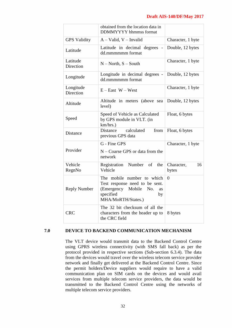
Draft AIS-140/DF/May 2017
32
obtained from the location data in
DDMMYYYY hhmmss format
GPS Validity A – Valid, V – Invalid Character, 1 byte
Latitude Latitude in decimal degrees -
dd.mmmmmm format
Double, 12 bytes
Latitude
Direction N – North, S – South
Character, 1 byte
Longitude Longitude in decimal degrees -
dd.mmmmmm format
Double, 12 bytes
Longitude
Direction E – East W – West
Character, 1 byte
Altitude Altitude in meters (above sea
level)
Double, 12 bytes
Speed Speed of Vehicle as Calculated
by GPS module in VLT. (in
km/hrs.)
Float, 6 bytes
Distance Distance calculated from
previous GPS data
Float, 6 bytes
Provider
G - Fine GPS
N – Coarse GPS or data from the
network
Character, 1 byte
Vehicle
RegnNo
Registration Number of the
Vehicle
Character, 16
bytes
Reply Number
The mobile number to which
Test response need to be sent.
(Emergency Mobile No. as
specified by
MHA/MoRTH/States.)
0
CRC
The 32 bit checksum of all the
characters from the header up to
the CRC field
8 bytes
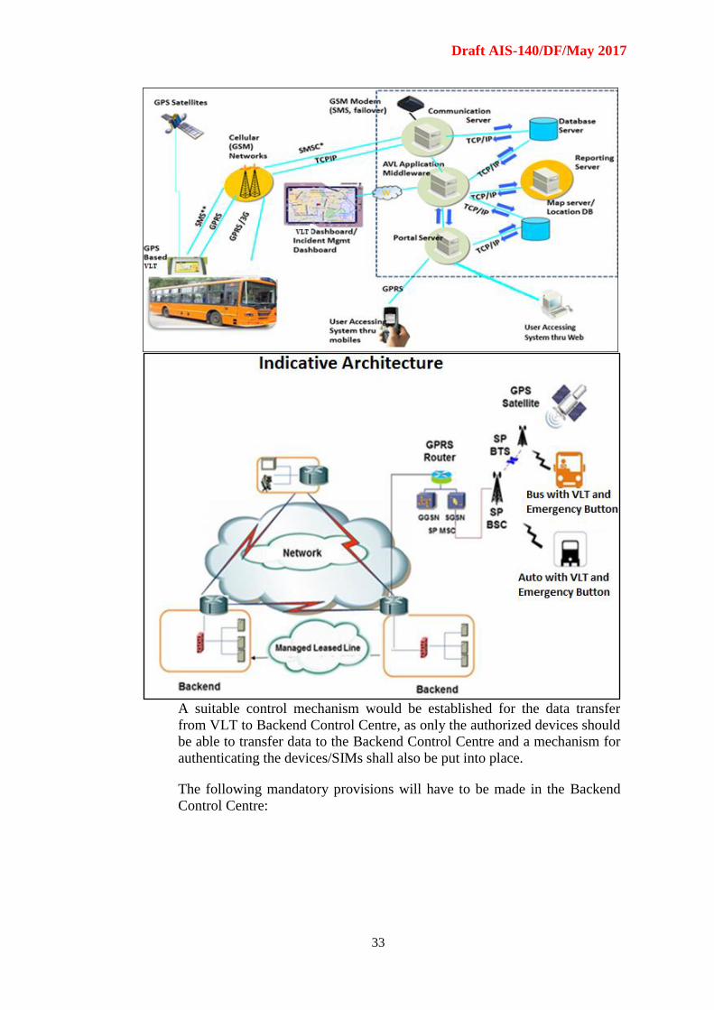
7.0 DEVICE TO BACKEND COMMUNICATION MECHANISM
The VLT device would transmit data to the Backend Control Centre
using GPRS wireless connectivity (with SMS fall back) as per the
protocol provided in respective sections (Sub-section 6.3.4). The data
from the devices would travel over the wireless telecom service provider
network and finally get delivered at the Backend Control Centre. Since
the permit holders/Device suppliers would require to have a valid
communication plan on SIM cards on the devices and would avail
services from multiple telecom service providers, the data would be
transmitted to the Backend Control Centre using the networks of
multiple telecom service providers.
Draft AIS-140/DF/May 2017
33
A suitable control mechanism would be established for the data transfer
from VLT to Backend Control Centre, as only the authorized devices should
be able to transfer data to the Backend Control Centre and a mechanism for
authenticating the devices/SIMs shall also be put into place.
The following mandatory provisions will have to be made in the Backend
Control Centre:
Draft AIS-140/DF/May 2017
34
1. Registration and activation of the device(s) fitted on the vehicle,
including the details of vehicle registration number, engine number,
chassis number, vehicle make and model, device make and model, and
telecom service provider’s name.
2. Re-registration/re-activation of the device(s) fitted on the vehicle in case
of any change in device or telecom service provider, etc.
3. Regular health check of the device(s) fitted on the vehicle, as per the
parameters and frequency defined in Sub-section 3.1.4.
4. Administration/configuration of devices for any changes in the
parameters as decided by the respective state from time to time.
5. Notification of alerts in case of press of an Alert Button fitted on the
vehicle, in the protocol defined in Section 4.
6. Notification of alerts in case of defined deviations by vehicle such as
over-speeding, deviation from defined route/geographic area, time of
operation, etc.
7. Location tracking of the vehicle including real-time as well as history
tracking for up to last 90 days.
8. Notification to the permit-holder through SMS in case any device(s)
stops functioning/sending data to the Backend Control Centre.
9. Reports of the vehicles with devices not working/sending data beyond
defined number of days (1 day, 3 days, 7 days and 30 days).
10. Ensure that the security and privacy of the data is maintained in
accordance with applicable laws/guidelines of various government
authorities.
In addition to the above mandatory provisions, the Backend Control Centre
can provide any other optional features.
The mechanism to set up the Backend Control Centre shall be decided by
the respective states. The states can chose any of the following options for
setting up the Backend Control Centre:
1. States can set up their own dedicated Backend Control Centre, meeting
the above listed mandatory provisions and any other optional features as
they may decide
2. States can allow telecom service providers to offer Backend Control
Centre as a Value Added Service (VAS) to the permit holders, meeting
the above listed mandatory provisions and any other optional features as
they may decide. In this case, the telecom service providers shall
provide access to the Backend Control Centre to government officials,
as decided by the respective state.
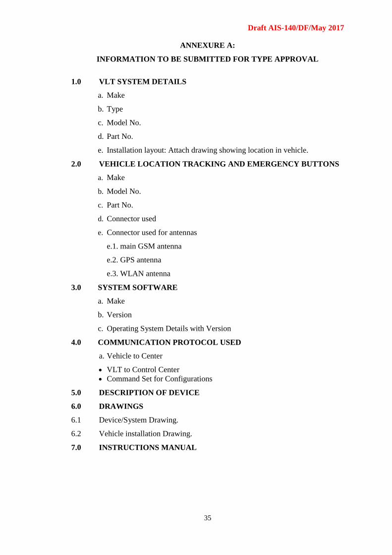
Draft AIS-140/DF/May 2017
35
ANNEXURE A:
INFORMATION TO BE SUBMITTED FOR TYPE APPROVAL
1.0 VLT SYSTEM DETAILS
a. Make
b. Type
c. Model No.
d. Part No.
e. Installation layout: Attach drawing showing location in vehicle.
2.0 VEHICLE LOCATION TRACKING AND EMERGENCY BUTTONS
a. Make
b. Model No.
c. Part No.
d. Connector used
e. Connector used for antennas
e.1. main GSM antenna
e.2. GPS antenna
e.3. WLAN antenna
3.0 SYSTEM SOFTWARE
a. Make
b. Version
c. Operating System Details with Version
4.0 COMMUNICATION PROTOCOL USED
a. Vehicle to Center
VLT to Control Center
Command Set for Configurations
5.0 DESCRIPTION OF DEVICE
6.0 DRAWINGS
6.1 Device/System Drawing.
6.2 Vehicle installation Drawing.
7.0 INSTRUCTIONS MANUAL
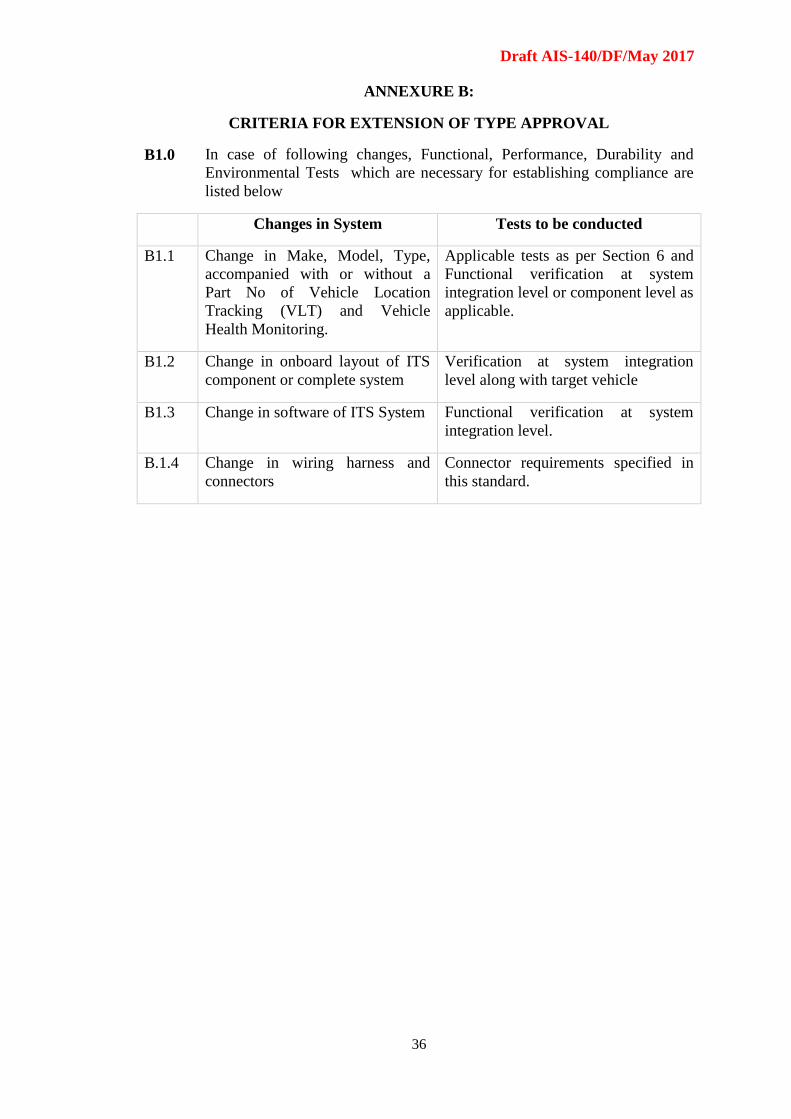
Draft AIS-140/DF/May 2017
36
ANNEXURE B:
CRITERIA FOR EXTENSION OF TYPE APPROVAL
B1.0 In case of following changes, Functional, Performance, Durability and
Environmental Tests which are necessary for establishing compliance are
listed below
Changes in System Tests to be conducted
B1.1 Change in Make, Model, Type,
accompanied with or without a
Part No of Vehicle Location
Tracking (VLT) and Vehicle
Health Monitoring.
Applicable tests as per Section 6 and
Functional verification at system
integration level or component level as
applicable.
B1.2 Change in onboard layout of ITS
component or complete system
Verification at system integration
level along with target vehicle
B1.3 Change in software of ITS System Functional verification at system
integration level.
B.1.4 Change in wiring harness and
connectors
Connector requirements specified in
this standard.
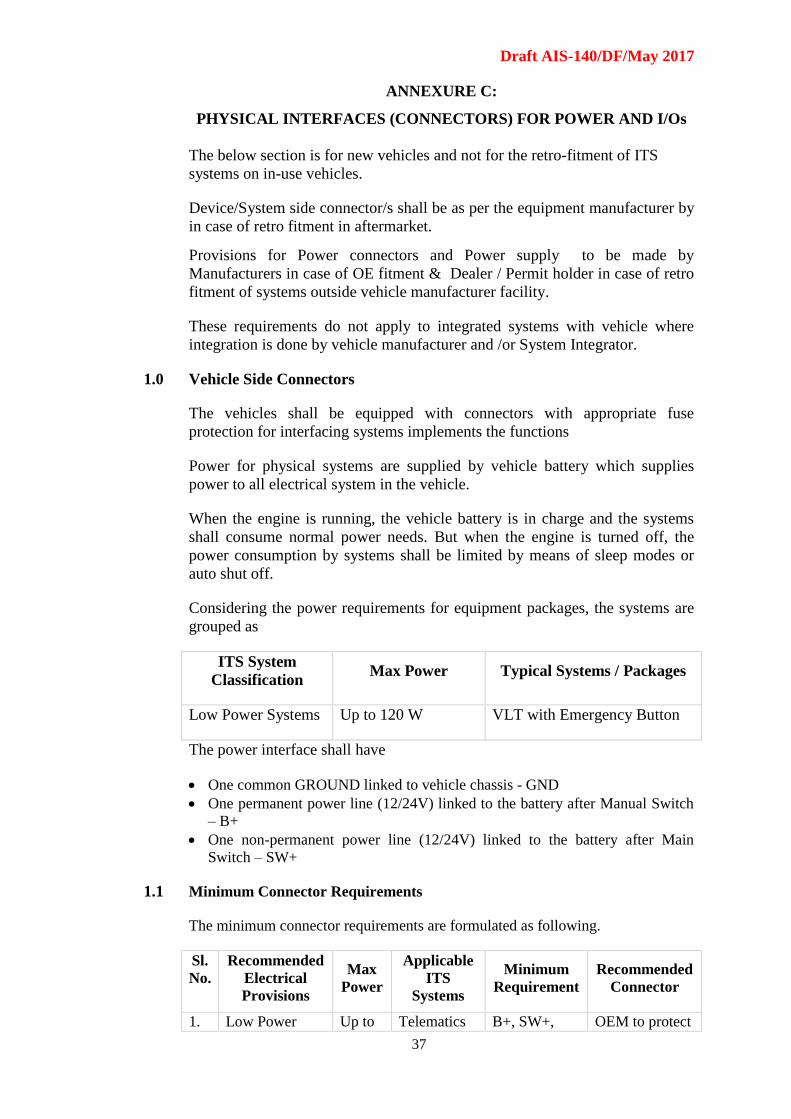
Draft AIS-140/DF/May 2017
37
ANNEXURE C:
PHYSICAL INTERFACES (CONNECTORS) FOR POWER AND I/Os
The below section is for new vehicles and not for the retro-fitment of ITS
systems on in-use vehicles.
Device/System side connector/s shall be as per the equipment manufacturer by
in case of retro fitment in aftermarket.
Provisions for Power connectors and Power supply to be made by
Manufacturers in case of OE fitment & Dealer / Permit holder in case of retro
fitment of systems outside vehicle manufacturer facility.
These requirements do not apply to integrated systems with vehicle where
integration is done by vehicle manufacturer and /or System Integrator.
1.0 Vehicle Side Connectors
The vehicles shall be equipped with connectors with appropriate fuse
protection for interfacing systems implements the functions
Power for physical systems are supplied by vehicle battery which supplies
power to all electrical system in the vehicle.
When the engine is running, the vehicle battery is in charge and the systems
shall consume normal power needs. But when the engine is turned off, the
power consumption by systems shall be limited by means of sleep modes or
auto shut off.
Considering the power requirements for equipment packages, the systems are
grouped as
ITS System
Classification Max Power Typical Systems / Packages
Low Power Systems Up to 120 W VLT with Emergency Button
The power interface shall have
One common GROUND linked to vehicle chassis - GND
One permanent power line (12/24V) linked to the battery after Manual Switch
– B+
One non-permanent power line (12/24V) linked to the battery after Main
Switch – SW+
1.1 Minimum Connector Requirements
The minimum connector requirements are formulated as following.
Sl.
No.
Recommended
Electrical
Provisions
Max
Power
Applicable
ITS
Systems
Minimum
Requirement
Recommended
Connector
1. Low Power Up to Telematics B+, SW+, OEM to protect

Draft AIS-140/DF/May 2017
38
System 1
(Mandatory
Provision)
120 W Device/VLT
System with
Emergency
Button
GND ISO 15170-B1-
3.1-Sn/K1
Socket
(Female)
Connector

Draft AIS-140/DF/May 2017
39
The OEM may provide optional auxiliary connectors of their choice for meeting
other functional requirements.
1.2 Connector labeling in Wiring Harness:
Vehicle side wiring shall have the following labeling for the connectors
Recommended Electrical
Provisions
Labeling Requirement
Low Power System 1
(Mandatory Provision)
ITS 120 W
Low Power System 2
(Mandatory Provision)
ITS 120 W
High Power System 1
(Mandatory Provision)
ITS 360 W
CAN Interface (OBDII CAN)
(Mandatory Provision)
ITS CAN
1.3 Connector Cavity/PIN Assignment
Power Connector: ISO 15170-B1-3.1-Sn/K1, ISO 15170-B2-3.1-Sn/K1
Pin 1 B+
Pin 2 SW+
Pin 3 GND
CAN Connector: ISO 15170-B1-4.1-Sn/K1
Pin 1 CAN High
Pin 2 CAN Low
Pin 3 Option CAN Ground
Pin 4 Not used
2.0 Device/System connectors
Device/System side connector/s shall be pre-agreed with equipment
manufacturer by
1. Vehicle OEM in the case of OE fitment of the systems
2. Permit holder or Dealer in case of retro fitment of systems outside vehicle
manufacturer facility
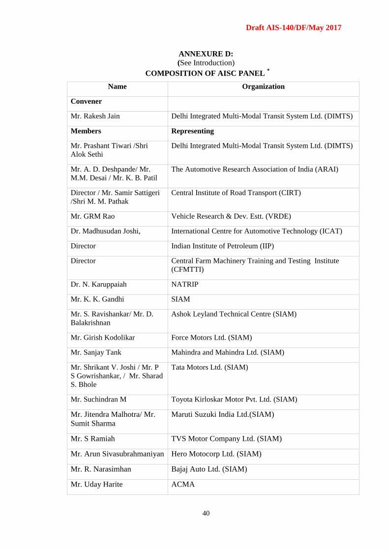
Draft AIS-140/DF/May 2017
40
ANNEXURE D:
(See Introduction)
COMPOSITION OF AISC PANEL *
Name Organization
Convener
Mr. Rakesh Jain Delhi Integrated Multi-Modal Transit System Ltd. (DIMTS)
Members Representing
Mr. Prashant Tiwari /Shri
Alok Sethi
Delhi Integrated Multi-Modal Transit System Ltd. (DIMTS)
Mr. A. D. Deshpande/ Mr.
M.M. Desai / Mr. K. B. Patil
The Automotive Research Association of India (ARAI)
Director / Mr. Samir Sattigeri
/Shri M. M. Pathak
Central Institute of Road Transport (CIRT)
Mr. GRM Rao Vehicle Research & Dev. Estt. (VRDE)
Dr. Madhusudan Joshi, International Centre for Automotive Technology (ICAT)
Director Indian Institute of Petroleum (IIP)
Director Central Farm Machinery Training and Testing Institute
(CFMTTI)
Dr. N. Karuppaiah NATRIP
Mr. K. K. Gandhi SIAM
Mr. S. Ravishankar/ Mr. D.
Balakrishnan
Ashok Leyland Technical Centre (SIAM)
Mr. Girish Kodolikar Force Motors Ltd. (SIAM)
Mr. Sanjay Tank Mahindra and Mahindra Ltd. (SIAM)
Mr. Shrikant V. Joshi / Mr. P
S Gowrishankar, / Mr. Sharad
S. Bhole
Tata Motors Ltd. (SIAM)
Mr. Suchindran M Toyota Kirloskar Motor Pvt. Ltd. (SIAM)
Mr. Jitendra Malhotra/ Mr.
Sumit Sharma
Maruti Suzuki India Ltd.(SIAM)
Mr. S Ramiah TVS Motor Company Ltd. (SIAM)
Mr. Arun Sivasubrahmaniyan Hero Motocorp Ltd. (SIAM)
Mr. R. Narasimhan Bajaj Auto Ltd. (SIAM)
Mr. Uday Harite ACMA

Draft AIS-140/DF/May 2017
41
Mr. N. K. Sharma Bureau of Indian Standards (BIS)
Mr. Rahul Jain Castmaster Mobitec India Pvt Ltd.
Mr. Jayant Wagh KPIT Cummins Infosystems Ltd
* At the time of approval of this Automotive Industry Standard (AIS)
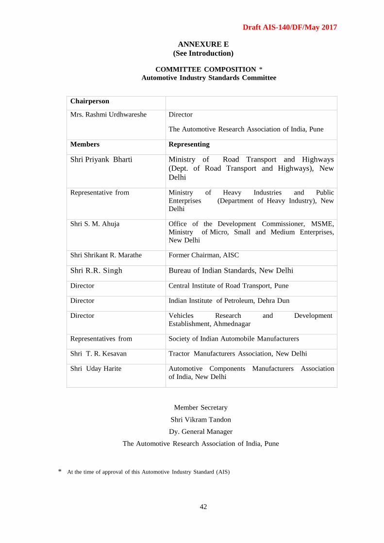
Draft AIS-140/DF/May 2017
42
ANNEXURE E
(See Introduction)
COMMITTEE COMPOSITION *
Automotive Industry Standards Committee
Chairperson
Mrs. Rashmi Urdhwareshe Director
The Automotive Research Association of India, Pune
Members Representing
Shri Priyank Bharti Ministry of Road Transport and Highways
(Dept. of Road Transport and Highways), New
Delhi
Representative from Ministry of Heavy Industries and Public
Enterprises (Department of Heavy Industry), New
Delhi
Shri S. M. Ahuja Office of the Development Commissioner, MSME,
Ministry of Micro, Small and Medium Enterprises,
New Delhi
Shri Shrikant R. Marathe Former Chairman, AISC
Shri R.R. Singh Bureau of Indian Standards, New Delhi
Director Central Institute of Road Transport, Pune
Director Indian Institute of Petroleum, Dehra Dun
Director Vehicles Research and Development
Establishment, Ahmednagar
Representatives from Society of Indian Automobile Manufacturers
Shri T. R. Kesavan Tractor Manufacturers Association, New Delhi
Shri Uday Harite Automotive Components Manufacturers Association
of India, New Delhi
Member Secretary
Shri Vikram Tandon
Dy. General Manager
The Automotive Research Association of India, Pune
* At the time of approval of this Automotive Industry Standard (AIS)