Embed Size (px)
Citation preview

I n t e r n a t i o n a l T e l e c o m m u n i c a t i o n U n i o n
I n te rnat iona lTe lecommun icat ionUn ion
*30101*Printed in Switzerland
Geneva, 2007ISBN 92-61-11871-2 Radiocommunication Bureau
INTELLIGENTTRANSPORT
SYSTEMS
Handbook onLand Mobile
(including Wireless Access)
Volume 4(Edition 2006)
INT
ELLIG
EN
T T
RA
NS
PO
RT
SY
ST
EM
S
La
nd
Mo
bil
e (
inclu
din
g W
ire
les
s A
cce
ss
) V
olu
me
4 –
Ed
itio
n 2
00
6
THE RADIOCOMMUNICATION SECTOR OF ITU
The role of the Radiocommunication Sector is to ensure the rational, equitable, efficient and economical use of the radio-frequency spectrum by all radiocommunication services, including satellite services, and carry out studies without limit of frequency range on the basis of which Recommendations are adopted.
The regulatory and policy functions of the Radiocommunication Sector are performed by World and Regional Radiocommunication Conferences and Radiocommunication Assemblies supported by Study Groups.
Inquiries about radiocommunication matters Please contact:
I T U Radiocommunication Bureau Place des Nations CH -1211 Geneva 20 Switzerland
Telephone: +41 22 730 5800 Fax: +41 22 730 5785 E-mail: [email protected] Web: www.itu.int/itu-r
Placing orders for ITU publicationsPlease note that orders cannot be taken over the telephone. They should be sent by fax or e-mail.
I T U Sales and Marketing Division Place des Nations CH -1211 Geneva 20Switzerland
Fax: +41 22 730 5194 E-mail: [email protected]
The Electronic Bookshop of ITU: www.itu.int/publications
ITU 2007
All rights reserved. No part of this publication may be reproduced, by any means whatsoever, without the prior written permission of ITU.

INTELLIGENT TRANSPORT SYSTEMS
Handbook on Land Mobile ( including Wire less Access)
Volume 4 ( E d i t io n 2 0 0 6 )
Radiocommunication Bureau

- iii -
Intelligent Transport Systems Foreword
Foreword
Intelligent transport systems (ITS) are defined as systems utilizing the combination of computers, communications, positioning, and automation technologies to improve the safety, management, and efficiency of terrestrial transportation.
This is the fourth volume of the ITU-R Handbook on Land Mobile (including Wireless Access). The development of this multi-volume Handbook was started in the late 1990s within the ITU-R to meet an increasing need by the developing countries for a handbook on state of the art technologies covering the various aspects of the land mobile service; including technologies and systems.
The three volumes that have already been published to-date are:
– Volume 1: Fixed Wireless Access
– Volume 2: Principles and Approaches on Evolution to IMT-2000
– Volume 3: Dispatch and Advanced Messaging Systems.
The purpose of the Handbook is to assist in the decision making process involving planning, engineering and deployment of wireless-based land mobile systems, especially in the developing countries. It should also provide adequate information that will assist in training engineers and planners in regulating, planning, engineering, and deployment aspects of these systems.
This Volume of the Handbook provides a summary of the use of wireless communications in ITS, current and under development, around the globe, including architecture, systems, and applications. This is a rapidly developing sector, which is still partly in its infancy. This Volume is representative of the time that it was produced, and so provides a description of wireless communications used in ITS as of the start of 2006.
Volume 4 has been developed by a group of experts of Radiocommunication Working Party 8A. I wish to express my appreciation to Ms. Reema Hafez (Canada), Land Mobile Handbook Rapporteur and Dr. Jongtaek Oh (Republic of Korea) who kindly served as editor of this volume, as well as to all the experts who contributed to the development of the Handbook.
José M. Costa Chairman, Radiocommunication Working Party 8A
Canada

Any-Bus is a trademark of SDS (Korean SI company); BREW is a trademark of Qualcomm; cdma2000 is a registered trademark of the TIA, in the United States of America, on behalf of the Organizational Partners of 3GPP2; K-ways is a trademark of KTF (Korean PCS service operator); OnStar is a trademark of OnStar Corporation; ROTIS is a trademark of ROTIS (Korean ITS company).

Intelligent Transport Systems Table of Contents
TABLE OF CONTENTS
Page
FOREWORD ......................................................................................................................... iii
CHAPTER 1 – INTRODUCTION ..................................................................................... 1
1.1 Purpose and scope of the Handbook on Land Mobile ........................................... 1
1.2 Background ............................................................................................................ 1
1.3 Organization and use of Volume 4 ........................................................................ 2
CHAPTER 2 – ITS COMMUNICATIONS ARCHITECTURE...................................... 3
2.1 Introduction............................................................................................................ 3
2.2 ITS goals ................................................................................................................ 3
2.3 ITS system architecture.......................................................................................... 3
2.4 Frequency allocation.............................................................................................. 6
2.4.1 DSRC spectrum ......................................................................................... 6
2.4.2 Millimetre-wave spectrum......................................................................... 7
2.5 Future trends .......................................................................................................... 7
CHAPTER 3 – ITS APPLICATIONS FOR WIDE AREA WIRELESS COMMU-NICATIONS AND BROADCASTING ............................................................... 9
3.1 Introduction............................................................................................................ 9
3.2 Cellular/PCS/IMT-2000......................................................................................... 9
3.2.1 CDMA2000 radio interface ....................................................................... 10
3.2.2 K-WAYSTM ............................................................................................... 11
3.2.2.1 Services........................................................................................ 11
3.2.2.2 Location finding technology........................................................ 13
3.2.2.3 Network architecture ................................................................... 14
3.2.3 ONSTAR ................................................................................................... 15
3.2.4 Digital cellular and digital broadcasting systems in Japan........................ 17
3.2.4.1 Digital cellular system................................................................. 17
3.2.4.2 Digital terrestrial broadcasting system ........................................ 17
- vi -
Table of Contents Intelligent Transport Systems
Page
3.2.5 European in-vehicle emergency call system eCall .................................... 18
3.2.5.1 Introduction ................................................................................. 18
3.2.5.2 eCall basic architecture................................................................ 19
3.3 BIS System using wireless data network ............................................................... 20
3.3.1 Introduction ............................................................................................... 20
3.3.2 Detection and tracking of bus location ...................................................... 20
3.3.3 Communication link to transmit location information .............................. 21
3.3.4 Implementation of public transportation information system ................... 22
3.3.4.1 Introduction ................................................................................. 22
3.3.4.2 Wireless packet data network of BMS system............................ 23
3.3.4.3 Central system of Seoul BMS ..................................................... 24
3.3.4.4 Local equipment of Seoul BMS .................................................. 25
3.3.4.5 Protocol between buses and central system................................. 25
3.3.5 Various models of bus information and management system................... 25
3.4 FM Broadcasting.................................................................................................... 26
3.4.1 DARC ........................................................................................................ 26
3.5 Future trends .......................................................................................................... 28
3.5.1 Mobile WiMax (WiBro) ............................................................................ 28
3.5.1.1 Description .................................................................................. 28
3.5.1.2 System configuration................................................................... 29
3.5.1.3 Key services................................................................................. 30
3.5.1.4 ITS with WiBro ........................................................................... 30
3.5.2 T-DMB ...................................................................................................... 30
3.5.2.1 T-DMB technology ..................................................................... 30
3.5.3 DVB-H....................................................................................................... 32
3.5.3.1 DVB-H Technology .................................................................... 32
3.5.4 FLO............................................................................................................ 32
3.5.4.1 FLO technology........................................................................... 33
- vii -
Intelligent Transport Systems Table of Contents
Page
3.5.5 Automatic crash notification (ACN) ......................................................... 33
3.5.5.1 Service objectives........................................................................ 33
3.5.5.2 ACN equipment features ............................................................. 34
3.5.5.3 ACN business case issues............................................................ 34
3.5.5.4 ACN cellular carrier issues.......................................................... 34
3.5.6 Internet in vehicle ...................................................................................... 35
3.5.7 Online maintenance ................................................................................... 35
3.5.8 VMS in vehicle.......................................................................................... 36
3.5.9 Satellite navigation with congestion avoidance......................................... 36
CHAPTER 4 – DEDICATED SHORT RANGE COMMUNICATIONS....................... 37
4.1 Introduction............................................................................................................ 37
4.2 European DSRC system and applications.............................................................. 39
4.2.1 Background................................................................................................ 39
4.2.2 Technical characteristics............................................................................ 39
4.2.2.1 Passive backscatter method ......................................................... 39
4.2.2.2 Technical characteristics of the European backscatter method... 41
4.2.3 Applications............................................................................................... 43
4.2.3.1 General ........................................................................................ 43
4.2.3.2 Electronic toll collection (ETC) .................................................. 43
4.2.3.3 Electronic registration identification (ERI) ................................. 44
4.2.3.4 Medium range pre-information (MRPI)...................................... 45
4.3 Japanese DSRC system and applications............................................................... 46
4.3.1 Background................................................................................................ 46
4.3.2 Technical characteristics............................................................................ 47
4.3.2.1 Active (transceiver) method ........................................................ 47
4.3.2.2 Technical characteristics of the Japanese active method ............ 48
4.3.3 Application sub layer (ASL) for multiple applications ............................. 49
4.3.4 Applications............................................................................................... 51
4.3.4.1 General ........................................................................................ 51
4.3.4.2 Electronic toll collection (ETC) .................................................. 53
4.3.4.3 Basic application interface to extend application in vehicles...... 54
- viii -
Table of Contents Intelligent Transport Systems
Page
4.4 ITS system using DSRC network .......................................................................... 54
4.4.1 Introduction ............................................................................................... 54
4.4.2 Model deployment initiatives .................................................................... 54
4.4.2.1 Key program elements................................................................. 57
4.4.2.2 Project management .................................................................... 57
4.4.3 Active DSRC ............................................................................................. 58
4.5 Future Trends: 5.9 GHz DSRC system and applications....................................... 60
4.5.1 Introduction ............................................................................................... 60
4.5.2 Functional requirements of next generation ITS radiocommunication systems....................................................................................................... 60
4.5.3 Requirements for the radio transmission technology ................................ 62
4.5.3.1 Characteristics of DSRC radio propagation ................................ 62
4.5.3.2 Considerations for DSRC propagation environment................... 64
4.5.3.3 Technology for next generation ITS radiocommunication ......... 64
4.5.4 Future DSRC system and applications in North America ......................... 65
4.5.4.1 Background.................................................................................. 65
4.5.4.2 Future DSRC system in North America...................................... 66
4.5.4.3 Proposed DSRC applications in North America ......................... 67
4.5.4.4 Future requirements and trends ................................................... 68
4.5.4.5 Internet concept and Protocol...................................................... 70
4.5.4.6 Internet Protocol based DSRC..................................................... 72
CHAPTER 5 – MILLIMETRE WAVE COMMUNICATIONS...................................... 75
5.1 Introduction............................................................................................................ 75
5.2 Vehicular radar....................................................................................................... 77
5.2.1 Background................................................................................................ 77
5.2.2 Low power vehicular radar at 60 GHz and 76 GHz .................................. 78
5.2.2.1 General ........................................................................................ 78
5.2.2.2 System requirements ................................................................... 79
5.2.3 Ultra wide band (UWB) radar ................................................................... 80
5.2.3.1 General ........................................................................................ 80
5.2.3.2 Situation in the United States of America. .................................. 80
5.2.3.3 Situation in Europe ...................................................................... 81

- ix -
Intelligent Transport Systems Table of Contents
Page
5.3 Future trends .......................................................................................................... 82
5.3.1 Background................................................................................................ 82
5.3.2 Millimetre-wave ITS radiocommunication study in ITU-R...................... 83
5.3.3 Propagation characteristics of millimetre wave for vehicle-to-vehicle communications......................................................................................... 83
5.3.3.1 Two-ray propagation model for millimetre wave ....................... 83
5.3.3.2 Results of field operational tests.................................................. 84
5.3.4 Inter-vehicle communications and radar ................................................... 87
5.3.4.1 Communication through radar..................................................... 87
5.3.4.2 Example of applications .............................................................. 88
ANNEX 1 – RESOURCES ................................................................................................ 91
1 The Americas ......................................................................................................... 91
2 Europe .................................................................................................................... 91
3 Japan ...................................................................................................................... 91
4 Korea...................................................................................................................... 92
ANNEX 2 – VICS .............................................................................................................. 93
1 Introduction............................................................................................................ 93
2 Outline of the system ............................................................................................. 93
3 Information distribution media .............................................................................. 94
3.1 FM multiplex broadcasting........................................................................ 94
3.2 Radio wave beacon.................................................................................... 95
ANNEX 3 – ITS SYSTEM USING RADIO BEACON ................................................ 97
1 Real-time traffic information collection system .................................................... 97
2 Traffic information collection system.................................................................... 98
3 BUS information (management) system................................................................ 98
4 Specifications......................................................................................................... 99
ANNEX 4 – A FUTURE ITS NETWORK ARCHITECTURE: CALM ...................... 101
1 Introduction............................................................................................................ 101
2 The CALM concept ............................................................................................... 102
3 CALM service types .............................................................................................. 103
4 CALM benefits ...................................................................................................... 103
5 CALM architecture ................................................................................................ 103
ANNEX 5 – LIST OF ACRONYMS ............................................................................... 105


- 1 -
Intelligent Transport Systems Chapter 1
CHAPTER 1
INTRODUCTION
1.1 Purpose and scope of the Handbook on Land Mobile
The Handbook on Land Mobile initiatives was started in the late 90’s within the ITU-R to meet an increasing need by the developing countries for a handbook on state of the art technologies covering the various aspects of the land mobile service; including technologies and systems. The Handbook is organized in several volumes, three of which are already published:
– Volume 1: Fixed Wireless Access
– Volume 2: Principles and Approaches on Evolution to IMT-2000
– Volume 3: Dispatch and Advanced Messaging Systems
The purpose of the Handbook is to assist in the decision making process involving planning, engineering and deployment of wireless based land mobile systems, especially in the developing countries. It should also provide adequate information that will assist in training engineers and planners in regulating, planning, engineering, and deployment aspects of these systems. The Handbook covers land mobile applications including, vehicular communications, in-building communication, out-of-building communication, as well as others such as intelligent transport systems (ITS) applications. Systems covered encompass cellular-based systems, messaging systems, dispatch systems, fixed wireless access, as well as ITS.
The users of this Handbook are likely to fall into one of two categories. The first category includes the decision makers and planners who would like the Handbook to provide them with enough information to aid in decision making on system choices as far as their suitability to meet their requirements. For this purpose, the Handbook provides analysis on the various systems taking into consideration factors such as traffic estimation and projection, frequency band and spectrum requirements, investments, regulation and policy requirements and experiences, deployment strategies, short and long term implications, as well as other elements that are required for decision making and planning purposes.
For the second category of users, engineers, the Handbook provides more in depth technical information on the characteristics of the various systems and applications, systems design, traffic analysis and estimation, spectrum estimation, channelling plans, cell design and selection, deployment strategy, mobile and base station equipment, as well as other pertinent information.
1.2 Background
The purpose and scope of Volume 4 of the Handbook on Land Mobile, is to provide information on ITS. ITS utilize the combination of computers, communications, positioning, and automation technologies to improve the safety, management, and efficiency of terrestrial transportation systems. There are many current applications of ITS discussed within this Handbook, as well as new applications planned for the future. Most people rely on some form of transportation in their everyday lives, therefore a tremendous amount of users stand to benefit from ITS on a daily basis.

- 2 -
Chapter 1 Intelligent Transport Systems
This Volume of the Handbook provides a summary of the use of wireless communications in ITS, current and under development, around the globe. This is a rapidly developing sector, which is still largely in its infancy. This Volume is representative of the time that it was produced, and so provides a description of wireless communications used in ITS as at the start of 2006.
1.3 Organization and use of Volume 4
Volume 4 is organized into a number of chapters providing key information to the reader, with detailed technical, operational, and regulatory information provided in the annexes. The introduction to the Volume is provided in Chapter 1. Chapter 2 provides information on the ITS communications architecture. Chapter 3 covers a number of ITS applications, and Chapter 4 deals specifically with dedicated short range communications. Chapter 5 discusses millimetre wave communications.
Annex 1 provides a number of useful ITS resources around the world. Annexes 2 and 3 provide detailed technical and operational descriptions of vehicle information and communication systems and ITS using radio beacon. Annex 4 contains a description of the CALM architecture. Annex 5 contains a list of acronyms used in this Volume.
- 3 -
Intelligent Transport Systems Chapter 2
CHAPTER 2
ITS COMMUNICATIONS ARCHITECTURE
2.1 Introduction ITS resolves and enhances traffic congestion and safety problems in transportation systems. For moving transportation systems, wireless and wireline communication systems are very essential in order to exchange several types of information between transport systems, control systems, and users. In this Chapter, the goal of an ITS system is briefly introduced in order to establish the fundamental concept of ITS. Additionally, ITS system architecture, including ITS communication architecture, is shown for clarification of the roles of the communication functions.
2.2 ITS goals ITS technologies have been encapsulated in a collection of interrelated user services for application to transportation problems. For example, the user services could be defined as shown in Table 1*.
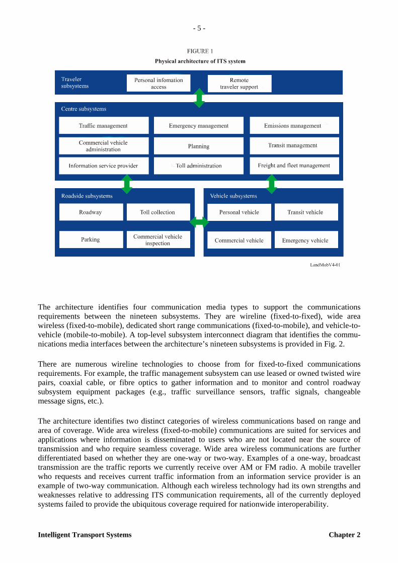
2.3 ITS system architecture The ITS architecture provides a common structure for the design of ITS. It is not a system design nor is it a design concept. What it does is define the framework around which multiple design approaches can be developed, each one specifically tailored to meet the individual needs of the user, while maintaining the benefits of a common architecture noted above. The architecture defines the functions (e.g., gather traffic information or request a route) that must be performed to implement a given user service, the physical entities or subsystems where these functions reside (e.g., the roadside or the vehicle), the interfaces/information flow between the physical subsystems, and the communication requirements for the information flow (e.g., wireline or wireless). In addition, it identifies and specifies the requirements for the standards needed to support national and regional interoperability, as well as product standards needed to support economies of scale considerations in deployment.
In Fig. 1, centre subsystems deal with those functions normally assigned to public/private administrative, management, or planning agencies. Roadside subsystems include functions that require convenient access to a roadside location for the deployment of sensors, signals, programmable signs, or other interfaces with travellers and vehicles of all types, and vehicle subsystems are installed in a vehicle. Traveller subsystems represent platforms for ITS functions of interest to travellers or carriers (e.g., commercial vehicle operators) in support of multimodal travelling. They may be fixed (e.g., kiosks or home/office computers) or portable (e.g., a palm-top computer), and may be accessed by the public (e.g., through kiosks) or by individuals (e.g., through cellular phones or personal computers).
____________________ * Reference: ITS National Architecture, U.S. DoT.

- 4 -
Chapter 2 Intelligent Transport Systems
TABLE 1
User services of ITS system
The ITS architecture provides the framework that ties the transportation and telecommunication worlds together to enable the development and effective implementation of the broad range of ITS user services. There are multiple communications options available to the system designer. The flexibility in choosing between various options allows each implementer the ability to select the specific technology that meets the local, regional, or national needs. The architecture identifies and assesses the capabilities of candidate communications technologies, but it does not select or recommend “winning” systems and technologies. One of the fundamental guiding philosophies in the development of the ITS architecture has been to leverage the existing and emerging transportation and communication infrastructures in its design. This minimizes the risk and cost of deployment, and maximizes marketplace acceptance, penetration, and early deployment.
Category User service
Travel and transportation management
– En-route driver information – Route guidance – Traveller services information – Traffic control – Incident management – Emissions testing and mitigation – Demand management and operations – Pre-trip travel information – Ride matching and reservation – Highway rail intersection
Public transportation operations
– Public transportation management – En-route transit information – Personalized public transit – Public travel security
Electronic payment – Electronic payment services
Commercial vehicle operations
– Commercial vehicle electronic clearance – Automated roadside safety inspection – On-board safety monitoring – Commercial vehicle administration processes – Hazardous materials
Emergency management – Emergency notification and personal security – Emergency vehicle management
Advanced vehicle control and safety systems
– Longitudinal collision avoidance – Lateral collision avoidance – Intersection collision avoidance – Vision enhancement for crash avoidance – Safety readiness – Pre-crash restraint deployment – Automated highway system
- 5 -
Intelligent Transport Systems Chapter 2
The architecture identifies four communication media types to support the communications requirements between the nineteen subsystems. They are wireline (fixed-to-fixed), wide area wireless (fixed-to-mobile), dedicated short range communications (fixed-to-mobile), and vehicle-to-vehicle (mobile-to-mobile). A top-level subsystem interconnect diagram that identifies the commu-nications media interfaces between the architecture’s nineteen subsystems is provided in Fig. 2.
There are numerous wireline technologies to choose from for fixed-to-fixed communications requirements. For example, the traffic management subsystem can use leased or owned twisted wire pairs, coaxial cable, or fibre optics to gather information and to monitor and control roadway subsystem equipment packages (e.g., traffic surveillance sensors, traffic signals, changeable message signs, etc.).
The architecture identifies two distinct categories of wireless communications based on range and area of coverage. Wide area wireless (fixed-to-mobile) communications are suited for services and applications where information is disseminated to users who are not located near the source of transmission and who require seamless coverage. Wide area wireless communications are further differentiated based on whether they are one-way or two-way. Examples of a one-way, broadcast transmission are the traffic reports we currently receive over AM or FM radio. A mobile traveller who requests and receives current traffic information from an information service provider is an example of two-way communication. Although each wireless technology had its own strengths and weaknesses relative to addressing ITS communication requirements, all of the currently deployed systems failed to provide the ubiquitous coverage required for nationwide interoperability.

- 6 -
Chapter 2 Intelligent Transport Systems
The second category, short range wireless, is concerned with information transfer that is of a localized interest. there are two types of short-range wireless communications identified by the architecture. they are vehicle-to-vehicle and dedicated short range communications (DSRC). vehicle-to-vehicle (mobile-to-mobile) short-range wireless communications are required to support the automated highway system (AHS), and most likely, intersection collision avoidance implementations. Appropriate applications for DSRC (fixed-to-mobile) include toll collection, parking fee collection, roadside safety inspections, credential checks, in-vehicle signing, intersection collision avoidance, and selected AHS communications (e.g., safety checks, access authorization, and system status updates).
2.4 Frequency allocation
The frequency spectrum for DSRC has been allocated in 5.8 GHz or 5.9 GHz band. Recommen-dation ITU-R M.1453-2 is based on DSRC in the ISM band from 5 725 to 5 875 MHz. In the millimetre frequency band, 76 to 77 GHz band has been allocated for low-power short range vehicle radar equipment. Recommendation ITU-R M.1452 deals with ITS use of this frequency band.
2.4.1 DSRC spectrum
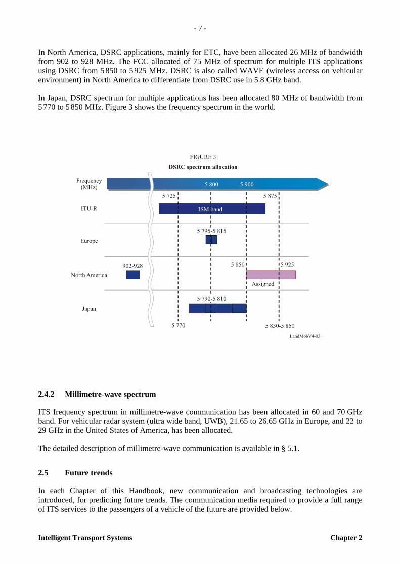
In Europe, DSRC applications, mainly used for ETC, have been allocated 20 MHz of bandwidth from 5 795 to 5 815 MHz. However, 5 805 to 5 815 MHz is optional for each country. In addition to this spectrum, study of additional spectrum for ITS multiple applications such as vehicle safety communications in the 5.9 GHz band is under the way.
- 7 -
Intelligent Transport Systems Chapter 2
In North America, DSRC applications, mainly for ETC, have been allocated 26 MHz of bandwidth from 902 to 928 MHz. The FCC allocated of 75 MHz of spectrum for multiple ITS applications using DSRC from 5 850 to 5 925 MHz. DSRC is also called WAVE (wireless access on vehicular environment) in North America to differentiate from DSRC use in 5.8 GHz band.
In Japan, DSRC spectrum for multiple applications has been allocated 80 MHz of bandwidth from 5 770 to 5 850 MHz. Figure 3 shows the frequency spectrum in the world.
2.4.2 Millimetre-wave spectrum
ITS frequency spectrum in millimetre-wave communication has been allocated in 60 and 70 GHz band. For vehicular radar system (ultra wide band, UWB), 21.65 to 26.65 GHz in Europe, and 22 to 29 GHz in the United States of America, has been allocated.
The detailed description of millimetre-wave communication is available in § 5.1.
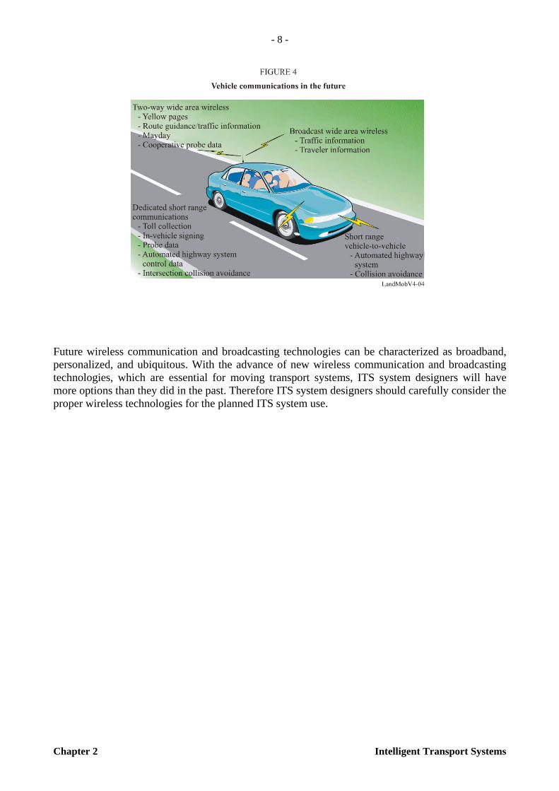
2.5 Future trends
In each Chapter of this Handbook, new communication and broadcasting technologies are introduced, for predicting future trends. The communication media required to provide a full range of ITS services to the passengers of a vehicle of the future are provided below.
- 8 -
Chapter 2 Intelligent Transport Systems
Future wireless communication and broadcasting technologies can be characterized as broadband, personalized, and ubiquitous. With the advance of new wireless communication and broadcasting technologies, which are essential for moving transport systems, ITS system designers will have more options than they did in the past. Therefore ITS system designers should carefully consider the proper wireless technologies for the planned ITS system use.
- 9 -
Intelligent Transport Systems Chapter 3
CHAPTER 3
ITS APPLICATIONS FOR WIDE AREA WIRELESS COMMUNICATIONS AND BROADCASTING
3.1 Introduction
Wide area wireless communications such as cellular-type networks and personal communication services (PCS) have been deployed successfully worldwide mainly for voice communication services. Recently, however, applications are rapidly expanding towards a rich array of data communications capabilities that include wireless Internet and video downloading. Moreover, traffic and alerting information has been carried out to drivers through cellular networks and broadcasting systems. Current and emerging air interfaces are designed to provide broadcast, multipoint multicasting, point-to-point, vehicle-to-vehicle, and vehicle-to-point communications that can be utilized in the ITS sector. These technologies are designed to enable quasi-continuous communications, or communications of protracted duration, between vehicles (or mobile terminals) and service providers, or between vehicles/mobile terminals and other entities. As such they are complementary to dedicated short range, single point technologies standardized in various regions of the world.
3.2 Cellular/PCS/IMT-2000
The fast movement of information across the longer distances using wireless technology is functionally very different from the requirements definition for DSRC. High volumes of data are required for purposes such as traffic information and management, video-downloads to vehicles for tourist information and entertainment and navigation system updates, etc.
Cellular/PCS/IMT-2000 networks can be effectively used to provide wide area wireless commu-nications and broadcasting involving narrowband to broadband applications. Around the world, there are many such service providers already in operation. Additionally, IMT-Advanced systems will also meet the criteria to be considered for ITS usage such as CALM, and as those systems are developed, they should also be considered in the context of this work. These standards are designed to enable quasi-continuous communications, or communications of protracted duration, and are complementary to dedicated short range, single point, technologies standardized in various regions of the world.
International Standards ISO 21212 and 21213 determine the air interface options applicable to CALM using 2G and 3G cellular technology and networks.
References for more architectural information and capabilities applicable to ITS include:
Recommendation ITU-R M.1457 – Detailed specifications of the radio interfaces of International Mobile Telecommunications-2000 (IMT-2000). (Note that some of these specifications, as indicated in the ISO CALM 3G document, are applicable to mobile wireless broadband for ITS CALM.)
- 10 -
Chapter 3 Intelligent Transport Systems
Recommendation ITU-R F.1763 – Radio interface standards for broadband wireless access systems in the fixed service operating below 66 GHz.
Recommendation ITU-R M.1645 – Framework and overall objectives of the future development of IMT-2000 and systems beyond IMT-2000.
In this section, summaries of deployed IMT specifications are given and the example of one service provider is used to demonstrate the types of services that can be provided.
3.2.1 CDMA2000 radio interface
The CDMA2000 radio interface, also known as IMT-2000 CDMA multi-carrier, currently supports various ITS related multi-media applications and specifies a secure spread spectrum radio interface that uses code division multiple access (CDMA) technology, including core air interface, minimum performance and service specifications. These spectral efficient specifications are designed to operate in cellular-type network architecture with the number of cells depending on coverage needs and deployed spectrum. This type of system and access solution is utilized in a number of regions of the world for multiple types of wireless cellular-type network architecture deployments involving fixed to mobile broadband wireless access services across metropolitan and wide area networks. The related CDMA2000 high rate packet data air interface (EV-DO) supports wireless access (up to vehicular speeds) over a wide-area and provides voice services and data services up to 3.1 Mbit/s on the downlink and 1.8 Mbit/s on the uplink, depending on mobility level. This evolution-oriented technology utilizes only a 1.25 MHz channel to provide high system capacity and flexibility. Work is ongoing to support increased channel banding and much higher peak data rates than mentioned. This technology is currently being deployed in support of ITS wide-area communication needs involving OnStar type services and high-speed data capability to deliver broadband access to the Internet, along with other advanced data services and public safety capabilities (i.e., emergency message delivery, PSAP caller ID and call-back).
It can also be noted that Greenfield wireless carriers and carriers that operate TDMA networks can deploy CDMA2000 (EV-DO) as an overlay network, to offer cost-effective mobility-oriented access to mobile devices, including in-vehicle, laptops, PDAs, and other access devices; also for a wide-range of Telematics applications and AGPS location-based services. CDMA2000 is also a defined ISO TC 204 CALM media interface for ITS applications:
ISO 21213: Intelligent transport systems – Communications, air-interface, long and medium range (CALM) – 3G Cellular systems
Additionally, the CDMA2000 development in 3GPP2 (developed in conjunction with and published by OPs) has adopted the IP multimedia subsystem (IMS), originally established by 3GPP, as the basis for the service architecture. 3GPP2 has also adopted the IMS construct within its multi-media domain (MMD) that includes IMS and the IMT-2000 CDMA multi-carrier packet data network. The 3GPP2 defined MMD network for CDMA2000 provides third generation (3G) capabilities and is based on Internet engineering task force (IETF) protocols, including SIP, SDP, diameter, and mobile IP. MMD supports features that certain administrations may require, such as lawful surveillance of signalling and bearer traffic. MMD will also be extended to support wireless VoIP and multimedia emergency calls and utilize AGPS-assisted position location for emergency services, telematics, ITS, and other applications.

- 11 -
Intelligent Transport Systems Chapter 3
Companion standards are available that provide various services, performance and testing requirements that define the network. CDMA2000 includes provisions for future service additions and expansion of system capabilities, and an architecture that permits such expansion without the loss of backward compatibility to older access terminals and defined systems.
This family of standards also includes broadcast-multicast service (BCMCS) standards (born out of 3GPP2) that allows for optimization for the use of the CDMA2000 radio interface for delivery of BCMCS content streams to terminals in an operator’s network. The operator can control each BCMCS content stream with regard to accounting aspects and regions of the network where the BCMCS content streams are available to various users. The content is encrypted to protect multicast IP flows against unauthorized reception. IETF protocols are widely employed whenever possible to minimize the number of new protocols required and to maximize the utilization of well accepted standards.
CDMA2000 is the trademark for the technical nomenclature for certain specifications and standards of the Organizational Partners (OPs) of 3GPP2 and geographically (and as of the date of publication) is a registered trademark of the Telecommunications Industry Association of the United States of America (TIA-USA).
TIA-2000.1-D [2004] Introduction to cdma2000® Spread Spectrum Systems.
TIA-856-A [EV-DO] [2004] cdma2000® High Rate Packet Data Air Interface Specification.
3.2.2 K-WAYS™
K-ways™ service is a digital convergence service that combines telecommunications and infotainment. This service includes a location-based service technology, and a wireless mobile communications technology. This service will become a leading driver in the service design and development of Telematics-related technologies.
3.2.2.1 Services
3.2.2.1.1 Service types
K-ways™ service is divided into three types according to the terminal form.

- 12 -
Chapter 3 Intelligent Transport Systems
Phone-type
The phone-type service provides a navigation service with only a handset that uses MS-based global positioning system (GPS) to fix the current position. This phone type navigation service is based on a WIPI platform which is used to communicate between the handset application and the service server. The handset downloads navigation data such as route planning data, route guidance data, map data, and POI data. In using the download data, the handset application executes the navigation service.
Kit type
The kit type service uses a handset to communicate with the server, and uses another GPS kit to receive the GPS signal. The kit type service is based on a WIPI platform and a BREW platform. With the mobile communication network, the handset receives the navigation data that is POI, R/P, R/G, and real-time traffic information.
Wide type
The wide type terminal is the navigation-only use terminal, which is connected with the handset to communicate with the server. The wide terminal can operate for itself, but it must communicate with the server by the handset to know the real time traffic information.
3.2.2.1.2 Service feature
Route planning and guidance service
The main service feature is the route planning and guidance service from the current position to the destination. With the GPS receiver, the position is fixed, and with R/P and R/G data, the navigation guide is made.
Real-time traffic information service
The real time traffic information service is another key feature. It makes a distinction between network connected-service and non connected-service.
POI service
The POI service gives users the position information on various locations such as a petrol station, a store, a restaurant, a hospital, etc.
Voice service
The voice service makes a call to the voice centre. When the user selects a destination or requests real-time traffic information, the voice response service is made. When the user is in danger, emergency service is possible.
- 13 -
Intelligent Transport Systems Chapter 3
3.2.2.2 Location finding technology
Traditionally, there have been two methods for providing wireless position location information: network-based solutions and handset-based solutions.
Network-based solutions rely on the signal transmitted from the wireless handset and received at multiple fixed base stations, using the angle of arrival (AoA) and the time of arrival (ToA) to determine position. Network-based solutions face a number of difficulties, including multi-path propagation, diffraction, weak signal conditions, base station availability and expensive upgrades.
Handset-based solutions make use of GPS, a worldwide system of 24 satellites and their ground stations. By accurately measuring the distance from three satellites, the receiver triangulates its position anywhere on earth. Handset-based solutions also face a number of challenges, including the GPS receiver state, and the inability of the handset to acquire satellites due to physical obstructions such as buildings, foliage and topography.
Presently, main technologies for K-ways™ service are using LBS platforms, LDT and application technologies. Application technology development is necessary for location determination technology advancement and various location base services.

- 14 -
Chapter 3 Intelligent Transport Systems
a) Cell ID based
– Cell information acquired by paging, locating area update, cell update, URA update.
– GMLC development completed.
b) OTDOA (see Note 1)
– Intersection information of minimum 3 Node-B RTT circle.
NOTE 1 – Low accuracy of multi-path and repeater. No plan for manufacturers for development.
c) Assisted GPS
– Communication information between GPS receiver of UE and GPS.
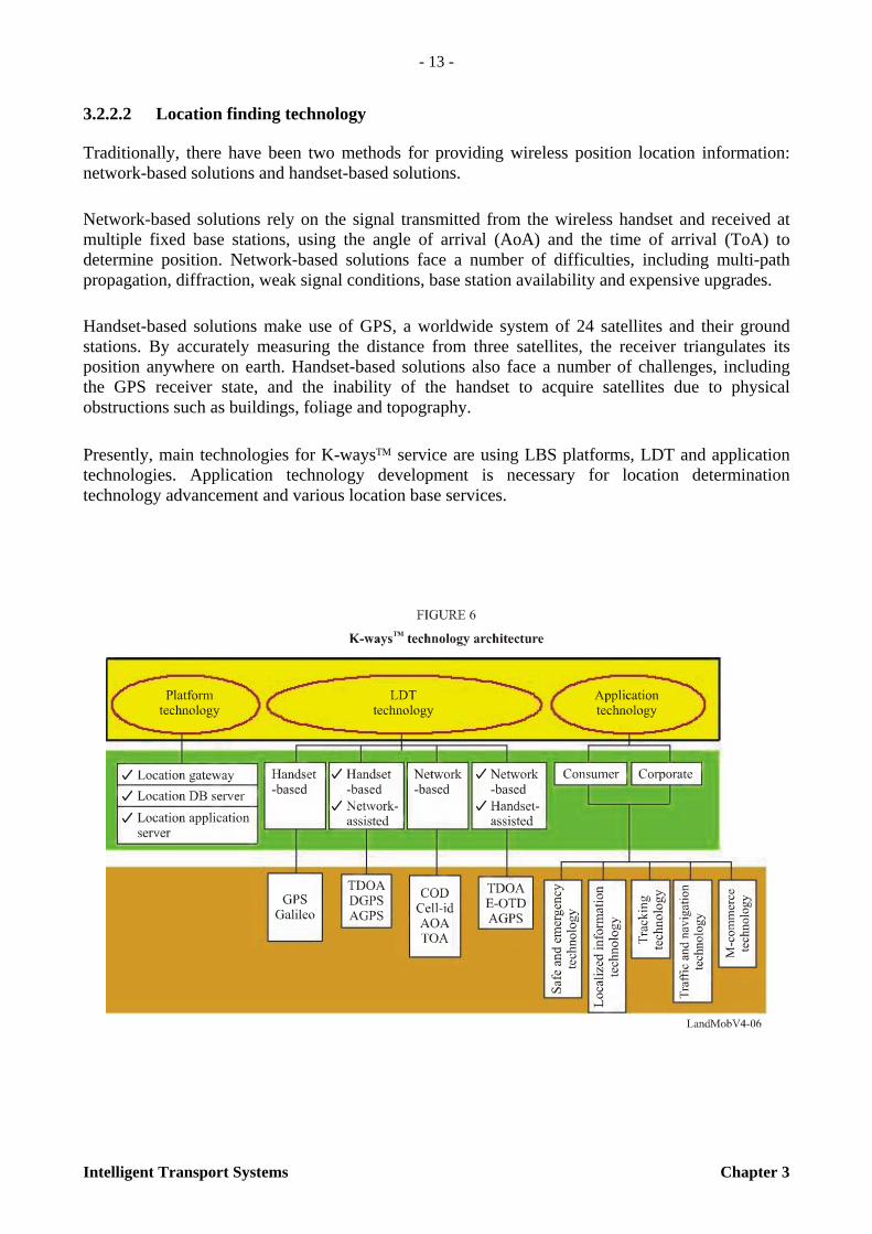
3.2.2.3 Network architecture
K-ways™ service’s hybrid approach merges GPS and network solutions by collecting measurements from the GPS constellation and CDMA (W-CDMA) network, then sending the information to position determination entity (PDE), located in the network, where the measurements are combined to produce an accurate multi-position.
- 15 -
Intelligent Transport Systems Chapter 3
3.2.3 ONSTAR
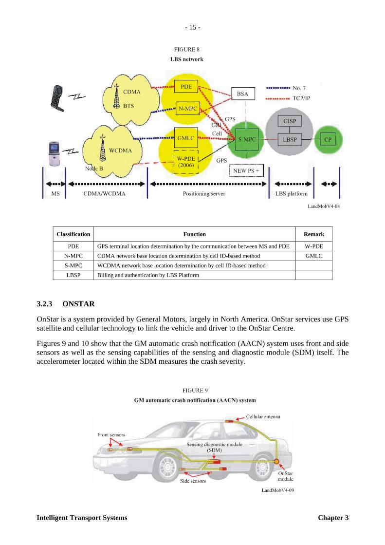
OnStar is a system provided by General Motors, largely in North America. OnStar services use GPS satellite and cellular technology to link the vehicle and driver to the OnStar Centre.
Figures 9 and 10 show that the GM automatic crash notification (AACN) system uses front and side sensors as well as the sensing capabilities of the sensing and diagnostic module (SDM) itself. The accelerometer located within the SDM measures the crash severity.
Classification Function Remark
PDE GPS terminal location determination by the communication between MS and PDE W-PDE
N-MPC CDMA network base location determination by cell ID-based method GMLC
S-MPC WCDMA network base location determination by cell ID-based method
LBSP Billing and authentication by LBS Platform
- 16 -
Chapter 3 Intelligent Transport Systems
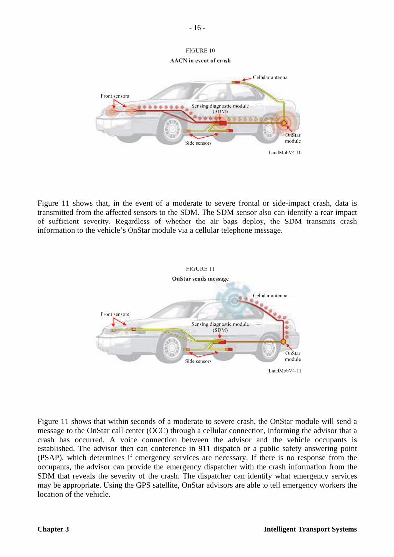
Figure 11 shows that, in the event of a moderate to severe frontal or side-impact crash, data is transmitted from the affected sensors to the SDM. The SDM sensor also can identify a rear impact of sufficient severity. Regardless of whether the air bags deploy, the SDM transmits crash information to the vehicle’s OnStar module via a cellular telephone message.
Figure 11 shows that within seconds of a moderate to severe crash, the OnStar module will send a message to the OnStar call center (OCC) through a cellular connection, informing the advisor that a crash has occurred. A voice connection between the advisor and the vehicle occupants is established. The advisor then can conference in 911 dispatch or a public safety answering point (PSAP), which determines if emergency services are necessary. If there is no response from the occupants, the advisor can provide the emergency dispatcher with the crash information from the SDM that reveals the severity of the crash. The dispatcher can identify what emergency services may be appropriate. Using the GPS satellite, OnStar advisors are able to tell emergency workers the location of the vehicle.
- 17 -
Intelligent Transport Systems Chapter 3
3.2.4 Digital cellular and digital broadcasting systems in Japan
3.2.4.1 Digital cellular system
In Japan, the number of 3G digital cellular subscribers (49 million) has exceeded the number of second generation subscribers (43 million) by the end of March 2006 and is still rapidly increasing.
Advanced traveller information service is one of the typical applications utilizing a digital cellular system. By proving real-time information to users of the surface transportation system, the advanced traveller information service contributes to making decisions about trip timing, trip mode choice, route choice, etc., that cannot be accomplished without up-to-date, accurate information on traffic, road, and weather conditions affecting these choices. Advanced traveller information service transmits information to users with Internet, wide area communications and broadcasting.
Advanced traveller information services are implemented by both the public and private sectors in Japan. There are two major public sector advanced traveller information systems. One is called vehicle information and communication system (VICS) service, which started in April 1996. Details of VICS are described in Annex 2 of this Handbook. Another service is called advanced traffic information service (ATIS), by ATIS Corporation, established by the metropolis of Tokyo and private associations in July 1993.
As for the private sector, auto manufacturers introduced their individual advanced traveller information services in 1998 but these systems did not become widely used and converged into integrated telematics services until 2002. The telematic services offered by Japan’s top three auto manufacturers are Toyota Motor’s “G-Book,” Honda Motor’s “InterNavi Premium Club” and Nissan Motor’s “Carwings”. They have been more favourably received by the user than their predecessors.
3.2.4.2 Digital terrestrial broadcasting system
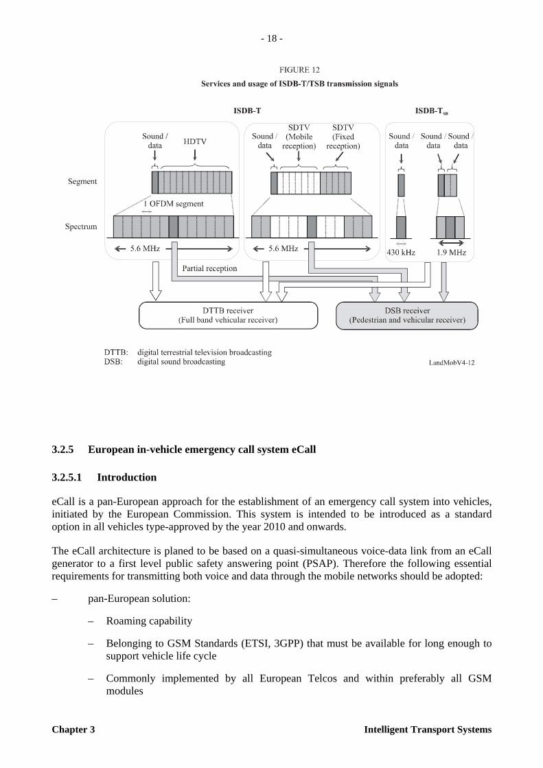
In Japan, terrestrial digital TV broadcasting service began in 2003 and terrestrial digital sound broadcasting service begins in 2006. These services offer the programs specifically targeted for portable terminals, including mobile phones, as part of the terrestrial digital programs. These services utilize one segment of Digital System C (ISDB-T: terrestrial digital TV broadcasting) and Digital System F (ISDB-TSB: terrestrial sound broadcasting). Figure 12 shows services and usage of ISDB-T/TSB transmission signals.
Various ITS applications are being studied for these broadcasting services.
- 18 -
Chapter 3 Intelligent Transport Systems
3.2.5 European in-vehicle emergency call system eCall
3.2.5.1 Introduction
eCall is a pan-European approach for the establishment of an emergency call system into vehicles, initiated by the European Commission. This system is intended to be introduced as a standard option in all vehicles type-approved by the year 2010 and onwards.
The eCall architecture is planed to be based on a quasi-simultaneous voice-data link from an eCall generator to a first level public safety answering point (PSAP). Therefore the following essential requirements for transmitting both voice and data through the mobile networks should be adopted:
– pan-European solution:
– Roaming capability
– Belonging to GSM Standards (ETSI, 3GPP) that must be available for long enough to support vehicle life cycle
– Commonly implemented by all European Telcos and within preferably all GSM modules
- 19 -
Intelligent Transport Systems Chapter 3
– Real-time transport mechanism
– Quasi simultaneous voice call and data transfer
– Secure transport and routing mechanism (E112)
– Automatic acknowledgement.
3.2.5.2 eCall basic architecture
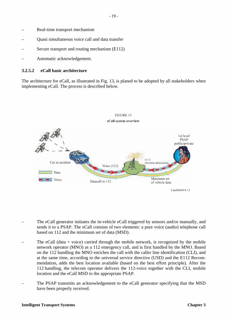
The architecture for eCall, as illustrated in Fig. 13, is planed to be adopted by all stakeholders when implementing eCall. The process is described below.
– The eCall generator initiates the in-vehicle eCall triggered by sensors and/or manually, and sends it to a PSAP. The eCall consists of two elements: a pure voice (audio) telephone call based on 112 and the minimum set of data (MSD).
– The eCall (data + voice) carried through the mobile network, is recognized by the mobile network operator (MNO) as a 112 emergency call, and is first handled by the MNO. Based on the 112 handling the MNO enriches the call with the caller line identification (CLI), and at the same time, according to the universal service directive (USD) and the E112 Recom-mendation, adds the best location available (based on the best effort principle). After the 112 handling, the telecom operator delivers the 112-voice together with the CLI, mobile location and the eCall MSD to the appropriate PSAP.
– The PSAP transmits an acknowledgement to the eCall generator specifying that the MSD have been properly received.

- 20 -
Chapter 3 Intelligent Transport Systems
An extended eCall system where additional vehicle and personal related information are provided from a service provider to a PSAP is envisaged.
Source: Recommendations of the DG eCall for the introduction of the pan-European eCall, [April 2006] Version 2.0.
3.3 BIS System using wireless data network
3.3.1 Introduction
A vehicle’s mobility decreases significantly in some cases of severe traffic congestion. In addition, inefficient mobility of vehicles triggers negative productivity, waste of energy and increase of vehicles’ exhaust gas, as well as possibly threatening lives.
The Ministry of Construction and Transportation of Korea enacted the law of Intelligent Transport Systems (Transportation System Efficiency Act, established on February 1999). On the basis of this act, several local autonomous cities have introduced ITS systems. However up to now, almost every ITS system was focused on vehicles and drivers, and did not take into consideration public transportation entities such as bus passengers, bus drivers and bus companies. Therefore recently, several local autonomous cities have introduced public transportation information systems to provide useful information for public travellers.
Unlike owner driven vehicles, vehicles used for public transportation, such as buses, are characterized by driving a designated route in a designated schedule, mainly for the public (e.g. students, workers, etc.). According to the results of a recent questionnaire for bus drivers and bus passengers at one of the local autonomous cities, bus drivers prefer to have an interval of time and distance between the preceding bus, their own bus and the bus running behind while bus passengers are concerned about their waiting time. In order to provide the appropriate information for the drivers and passengers, PTIS (Public Transportation Information System) was developed to not only collect necessary data from a moving bus, but to also provide value-added information after processing the data.
This PTIS comprises of an in-vehicle terminal, bus station display, communication link and central system. From a telecommunications point of view, it is composed of a location detecting system, a path tracking system, and a wireless communication link to transmit the location information.
This section describes the PTIS design technique, an introduction to the detection of bus location, the wireless communication network, and the implementation case of PTIS in Seoul, Korea, including the applied wireless packet data communication network in which Any-Bus I model was applied.
3.3.2 Detection and tracking of bus location
The detection method of locating moving buses consists of coordinates for detection using GPS, and Spot detection for small cell area detection.
– Coordinates detection method: Calculates the latitude and longitude of the bus using GPS signals, including accurate time.

- 21 -
Intelligent Transport Systems Chapter 3
– Spot detection method:
– Beacon: 223 987.5 kHz – 224 137.5 kHz (6 ch, 25 kHz/ch), 4.8 kbit/s, 5-50 m cell area
– DSRC: 5 790 MHz – 5 811 MHz (2 ch, 10 MHz/ch), 1 024 kbit/s, about 100 m cell area
– Wireless LAN: Commercial 801.11 b/g/a, about several 100 m cell area application
– Basis of system design: bus onboard-terminal continuously tracks the detected location-coordinates to calculate the travel time between links of the road network and average travel time, which is to be memorized in a database.
Although the coordinates method using GPS has a very high degree of accuracy, malfunctions can occur in locations such as underground parking lots, among high-rise buildings and under an overpasses, due to the attenuation of GPS signals. On the other hand, the spot detection method has very coarse accuracy, with a deviation of several tens of metres; however, the spot method is not able to detect an unexpected situation (i.e. accidents, sudden traffic jam, etc.) while driving between two cells. Also, it is difficult to calculate real time characteristics of traffic flow continuously. In order to overcome the spot cell problem, several antennas can be installed.
Therefore, a hybrid system using the GPS and spot detection methods can provide improved quality of location accuracy.
3.3.3 Communication link to transmit location information
The communication network is the most important factor for transmitting location information of moving vehicles. As the communication network needs a wide cell coverage area, it is difficult for a private company or a local autonomous city to install the network anew. Therefore, several cities have decided to lease the existing private-owned communication networks at large communication expenses:
– Several wireless communication industries in Korea:
– Wireless packet data network: 898-900 MHz, 938-940 MHz (60 ch, 12.5 kHz/ch, 9.6 kbit/s)
– Digital cellular network: 824-849 MHz, 869-894 MHz, 1 750-1 780 MHz, 1 840-1 870 MHz (14.4-144 kbit/s)
– TRS (trunk radio system): 805-821 MHz, 851-866 MHz (18 kbit/s)
– Basis of system design:
Additional data communication services of digital cellular networks, which were originally intended for voice transmissions, are used for the transmission of bus location data. As a result, it takes approximately 10 s for a call set-up time at a cellular base station, and 1.5 s for location data transmission. Moreover, when there are a number of buses, namely subscribers, the ordinary voice communication subscriber will experience a high volume of traffic.
Alternatively, wireless packet data network (WDN), having very fast set-up time and originally dedicated to digital data communication, has been commonly used for the collection and provision of traffic information.
- 22 -
Chapter 3 Intelligent Transport Systems
From an ITS service point of view, the digital cellular network and TRS network can be applied to medium sized cities, which have less severe traffic conditions and fewer buses (500 or less). However, it is necessary for large cities, which may have more than 1 000 buses, to have an appropriate communication network as follows:
– Real time communication due to very short call set-up time
– Bulky message, short and burst type message can be linked
– Less effect during a specific period such as rush-hour time, incidents and so on.
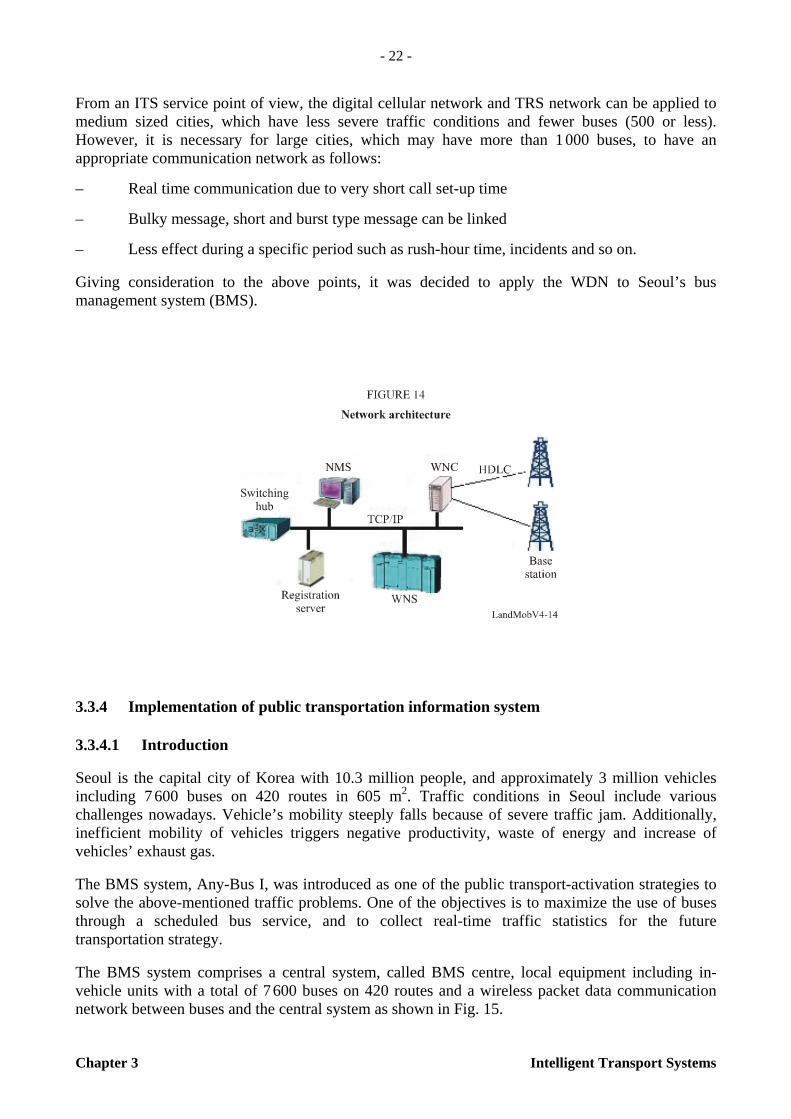
Giving consideration to the above points, it was decided to apply the WDN to Seoul’s bus management system (BMS).
3.3.4 Implementation of public transportation information system
3.3.4.1 Introduction
Seoul is the capital city of Korea with 10.3 million people, and approximately 3 million vehicles including 7 600 buses on 420 routes in 605 m2. Traffic conditions in Seoul include various challenges nowadays. Vehicle’s mobility steeply falls because of severe traffic jam. Additionally, inefficient mobility of vehicles triggers negative productivity, waste of energy and increase of vehicles’ exhaust gas.
The BMS system, Any-Bus I, was introduced as one of the public transport-activation strategies to solve the above-mentioned traffic problems. One of the objectives is to maximize the use of buses through a scheduled bus service, and to collect real-time traffic statistics for the future transportation strategy.
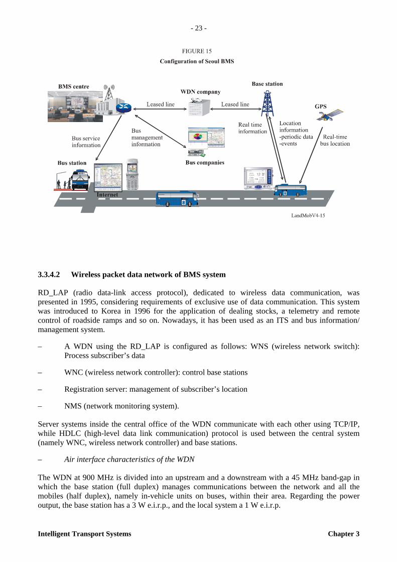
The BMS system comprises a central system, called BMS centre, local equipment including in-vehicle units with a total of 7 600 buses on 420 routes and a wireless packet data communication network between buses and the central system as shown in Fig. 15.
- 23 -
Intelligent Transport Systems Chapter 3
3.3.4.2 Wireless packet data network of BMS system
RD_LAP (radio data-link access protocol), dedicated to wireless data communication, was presented in 1995, considering requirements of exclusive use of data communication. This system was introduced to Korea in 1996 for the application of dealing stocks, a telemetry and remote control of roadside ramps and so on. Nowadays, it has been used as an ITS and bus information/ management system.
– A WDN using the RD_LAP is configured as follows: WNS (wireless network switch): Process subscriber’s data
– WNC (wireless network controller): control base stations
– Registration server: management of subscriber’s location
– NMS (network monitoring system).
Server systems inside the central office of the WDN communicate with each other using TCP/IP, while HDLC (high-level data link communication) protocol is used between the central system (namely WNC, wireless network controller) and base stations.
– Air interface characteristics of the WDN
The WDN at 900 MHz is divided into an upstream and a downstream with a 45 MHz band-gap in which the base station (full duplex) manages communications between the network and all the mobiles (half duplex), namely in-vehicle units on buses, within their area. Regarding the power output, the base station has a 3 W e.i.r.p., and the local system a 1 W e.i.r.p.

- 24 -
Chapter 3 Intelligent Transport Systems
Larger cells mean long path link delays and shadowing. Therefore, in considering frequency reuse distance and frequency directive characteristics, the cell plan was redesigned with 3 sectors per base station inside of the central area of Seoul, so that the communication performance between the buses and BMS central system could reach up to 99%. Major characteristics of frequency are outlined in Table 2.
TABLE 2
Technical specification of wireless packet data network
– Functional characteristics of the WDN
This WDN using RD_LAP protocol was designed for an exclusive use of data communication by nature. Thus WDN was applied to the ITS application due to the advantage of a real time response, a simultaneous subscriber connectivity, data communication performance and so on. From an ITS point of view, the WDN has the following important characteristics:
– No necessity for call set-up time
– A total of 20 000 subscribers per base station (2 000 subscribers per channel).
3.3.4.3 Central system of Seoul BMS
– Data collection subsystem
Location information obtained by GPS is processed as periodic data and event data, which are transmitted to a central system via wireless packet data communication. In the case of periodic data, information including current location and average vehicle speed is transmitted at 20-s intervals.
Occasionally, when the bus arrives at or leaves the bus station, there may be abnormal situations such as accidents or malfunction of the bus. In such cases, the driver will send the event data to the central system with ease of operation of the in-vehicle unit.
– Data processing subsystem
Several server systems process the collected data to obtain the estimated arrival time to a bus station, as well as the time and distance intervals between the preceding bus and the one running behind. Utilizing the data, abundant statistical analysis enables the manager of the BMS centre to carry out trend analysis in order to plan services more effectively for the future.
Item Remarks
Frequency band Outbound 938~940 MHz, Inbound : 898~900 MHz
Channel, bandwidth 60 channels, 12.5 kHz/channel
Rate, modulation 9 600 bit/s, 4-Level FSK, 3/4 Trellis coding
RF output (e.i.r.p.) Outbound 3 W (full duplex), inbound 1 W (half duplex)
- 25 -
Intelligent Transport Systems Chapter 3
– Information subsystem
All bus drivers may keep regular dispatch intervals and drive on schedule with the help of location information. Passengers can obtain a wide variety of information via Internet, cellular phone and PDA, as well as by message sign-boards at bus stations. Information obtained via the Internet can be presented in a variety formats depending on a user’s preferences or requirements.
3.3.4.4 Local equipment of Seoul BMS
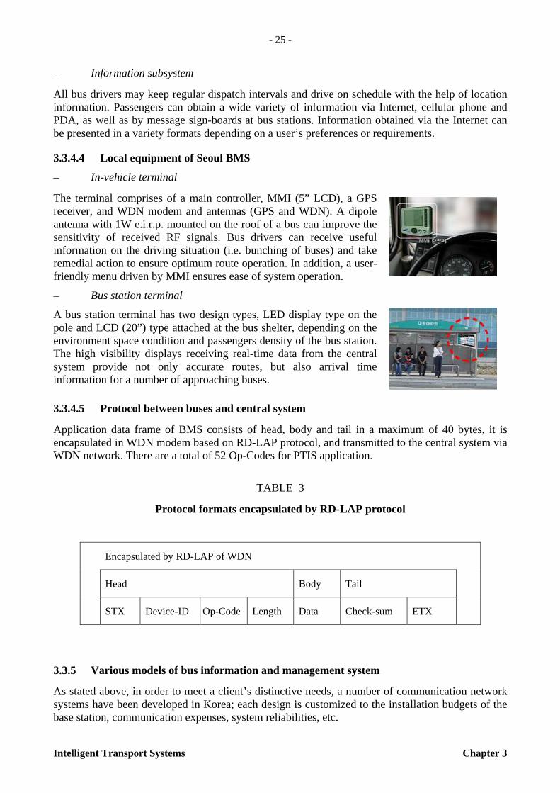
– In-vehicle terminal
The terminal comprises of a main controller, MMI (5” LCD), a GPS receiver, and WDN modem and antennas (GPS and WDN). A dipole antenna with 1W e.i.r.p. mounted on the roof of a bus can improve the sensitivity of received RF signals. Bus drivers can receive useful information on the driving situation (i.e. bunching of buses) and take remedial action to ensure optimum route operation. In addition, a user-friendly menu driven by MMI ensures ease of system operation.
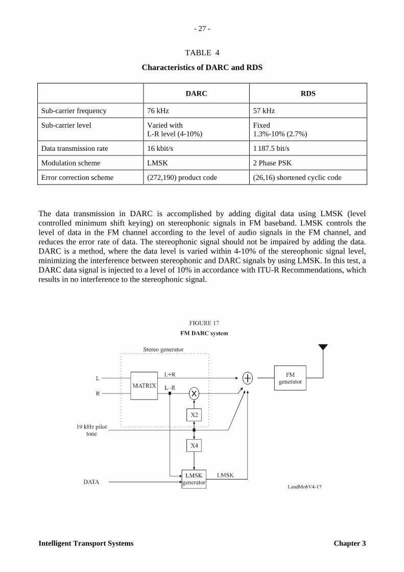
– Bus station terminal
A bus station terminal has two design types, LED display type on the pole and LCD (20”) type attached at the bus shelter, depending on the environment space condition and passengers density of the bus station. The high visibility displays receiving real-time data from the central system provide not only accurate routes, but also arrival time information for a number of approaching buses.
3.3.4.5 Protocol between buses and central system
Application data frame of BMS consists of head, body and tail in a maximum of 40 bytes, it is encapsulated in WDN modem based on RD-LAP protocol, and transmitted to the central system via WDN network. There are a total of 52 Op-Codes for PTIS application.
TABLE 3
Protocol formats encapsulated by RD-LAP protocol
3.3.5 Various models of bus information and management system
As stated above, in order to meet a client’s distinctive needs, a number of communication network systems have been developed in Korea; each design is customized to the installation budgets of the base station, communication expenses, system reliabilities, etc.
Encapsulated by RD-LAP of WDN
Head Body Tail
STX Device-ID Op-Code Length Data Check-sum ETX

- 26 -
Chapter 3 Intelligent Transport Systems
The Any-Bus I model has the GPS based location detection and WDN communication link in the cities of Seoul, Su-won and An-yang, and for the capital area a BIS system, which is the largest system.
The Any-Bus II model is a supplements model with wireless mesh LAN or beacons, especially in a central or core area of downtown. In the case where the networks are installed privately by the local autonomous city, the wireless mesh LAN is used for spot detection and communication to the central system without additional communications expenses. This mesh has mobile routing characteristics at the mobile terminal so that Any-Bus II model can form an ad-hoc network easily without wired connection.
The Any-Bus III model has GPS based location detection, wireless LAN and the existing digital cellular networks instead of the WDN. This model is appropriate where the city is small scale and has no current WDN network.
3.4 FM Broadcasting
3.4.1 DARC
FM DARC (data radio channel) sub-carrier system was developed for data transmission services including traffic information, and is used well as a major data traffic and traveller information service system in Korea, Japan and some European countries.
FM stereo broadcast is permitted to use 100 kHz baseband to transmit stereophonic signals, but it uses only 53 kHz of bandwidth. Therefore, the redundant 53-100 kHz of bandwidth could be used for other digital data or stereophonic services. Some methods for the utilization of this redundancy include radio(B) data systems (R(B)DS), which have a low transmission rate of 1 187.5 bit/s, and DARC, which have a high transmission rate of 16 kbit/s. Figure 16 shows the baseband spectrum of FM stereo broadcast including RDS and DARC signals and Table 4 presents the characteristics of DARC and RDS.
- 27 -
Intelligent Transport Systems Chapter 3
TABLE 4
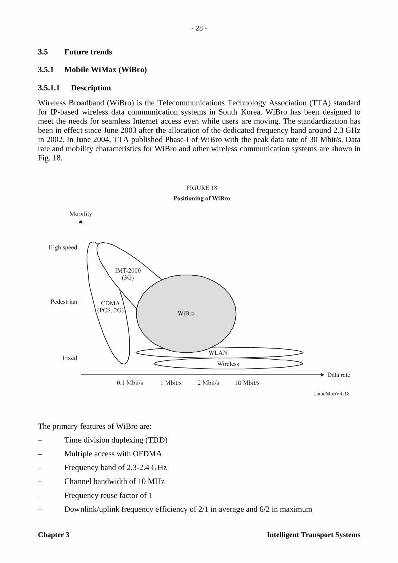
Characteristics of DARC and RDS
The data transmission in DARC is accomplished by adding digital data using LMSK (level controlled minimum shift keying) on stereophonic signals in FM baseband. LMSK controls the level of data in the FM channel according to the level of audio signals in the FM channel, and reduces the error rate of data. The stereophonic signal should not be impaired by adding the data. DARC is a method, where the data level is varied within 4-10% of the stereophonic signal level, minimizing the interference between stereophonic and DARC signals by using LMSK. In this test, a DARC data signal is injected to a level of 10% in accordance with ITU-R Recommendations, which results in no interference to the stereophonic signal.
DARC RDS
Sub-carrier frequency 76 kHz 57 kHz
Sub-carrier level Varied with L-R level (4-10%)
Fixed 1.3%-10% (2.7%)
Data transmission rate 16 kbit/s 1 187.5 bit/s
Modulation scheme LMSK 2 Phase PSK
Error correction scheme (272,190) product code (26,16) shortened cyclic code
- 28 -
Chapter 3 Intelligent Transport Systems
3.5 Future trends
3.5.1 Mobile WiMax (WiBro)
3.5.1.1 Description
Wireless Broadband (WiBro) is the Telecommunications Technology Association (TTA) standard for IP-based wireless data communication systems in South Korea. WiBro has been designed to meet the needs for seamless Internet access even while users are moving. The standardization has been in effect since June 2003 after the allocation of the dedicated frequency band around 2.3 GHz in 2002. In June 2004, TTA published Phase-I of WiBro with the peak data rate of 30 Mbit/s. Data rate and mobility characteristics for WiBro and other wireless communication systems are shown in Fig. 18.
The primary features of WiBro are:
– Time division duplexing (TDD)
– Multiple access with OFDMA
– Frequency band of 2.3-2.4 GHz
– Channel bandwidth of 10 MHz
– Frequency reuse factor of 1
– Downlink/uplink frequency efficiency of 2/1 in average and 6/2 in maximum
- 29 -
Intelligent Transport Systems Chapter 3
– Frame length of 5 ms with 1 024 FFT
– Channel coding with convolution turbo code
– Modulation with QPSK, 16-QAM, 64-QAM (downlink only)
– Asymmetric data transfer rate (uplink 128 kbit/s ~ 1 Mbit/s, downlink 512 kbit/s ~ 3 Mbit/s)
– User environments of nomadic, pedestrian, and medium speed of vehicles
– Handoff between cells (hard handoff)
– IP layer mobility support using mobile IPv4/v6
– Security using EAP and diameter/radius
– Various types of user terminal (notebook, PDA, smart phone).
WiBro is a subset of IEEE Std 802.16. The Korean Ministry of Information and Communication has chosen 3 service providers and given them license to start the commercial service. Those service providers are obligated to begin the service before October 2006.
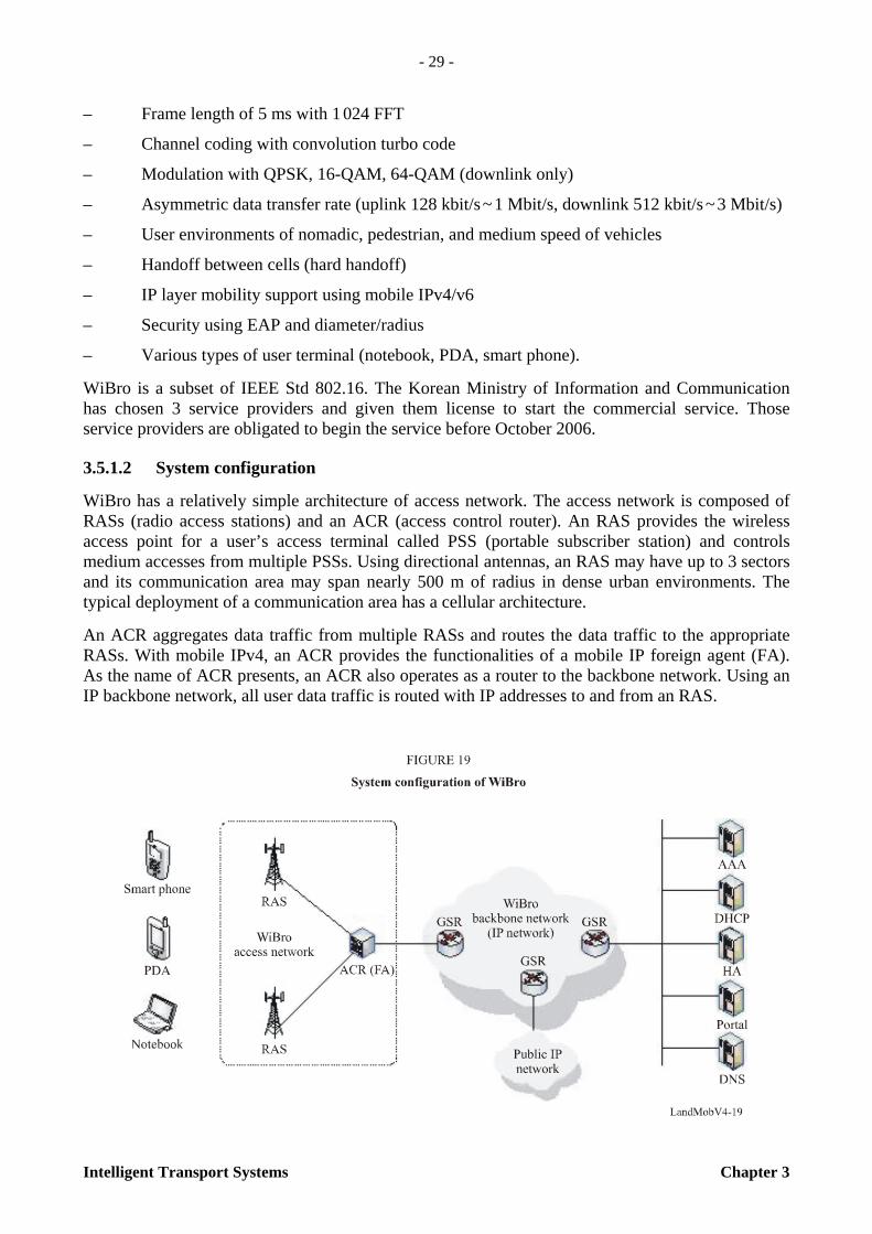
3.5.1.2 System configuration
WiBro has a relatively simple architecture of access network. The access network is composed of RASs (radio access stations) and an ACR (access control router). An RAS provides the wireless access point for a user’s access terminal called PSS (portable subscriber station) and controls medium accesses from multiple PSSs. Using directional antennas, an RAS may have up to 3 sectors and its communication area may span nearly 500 m of radius in dense urban environments. The typical deployment of a communication area has a cellular architecture.
An ACR aggregates data traffic from multiple RASs and routes the data traffic to the appropriate RASs. With mobile IPv4, an ACR provides the functionalities of a mobile IP foreign agent (FA). As the name of ACR presents, an ACR also operates as a router to the backbone network. Using an IP backbone network, all user data traffic is routed with IP addresses to and from an RAS.
- 30 -
Chapter 3 Intelligent Transport Systems
3.5.1.3 Key services
All types of services based on IP can be provided with WiBro. With its all-IP network architecture and higher data rates, WiBro will provide users with improved wireless Internet access. MMS and multimedia instant messenger using SIP protocol will be provided as a basic service. VoIP will be adopted as the core technology for voice communication and PTT. To meet the user needs for differentiated and personalized services, xOD, LBS, and telematics will be provided as supplementary services. The most outstanding service feature of WiBro will be the convergence of various services, e.g. with DMB (satellite/terrestrial digital multimedia broadcasting) and with CDMA or WLAN.
3.5.1.4 ITS with WiBro
It is anticipated that WiBro will be widely used as the primary system for the delivery of driving assistance information, such as real-time traffic and navigation information, specifically in multimedia format. As the infrastructure for gathering and processing of traffic information is being widely deployed, especially in such applications as loop, DSRC, CCTV, and probe cars, the need for an efficient information delivery system in vehicular environments has become more significant. By increasing user requirements for both the volume and quality of the delivered information, data transfer rates and costs have been the critical factors for choosing the wireless data systems.
With the trend of convergence of ITS, LBS, and telematics, ITS will take the main role of traffic and transportation information gathering, while LBS will be key for positioning and telematics for information delivery. For the positioning, GPS will be widely used, specifically AGPS (assisted GPS) embedded with the user terminal. In order to compensate for the limits of service coverage and user terminal mobility, a dual-band and dual-mode terminal integrated with CDMA can be used.
3.5.2 T-DMB
T-DMB (terrestrial digital multimedia broadcasting) is a new mobile multimedia broadcasting service. It enables the public to utilise multimedia services in their cars, in buildings and on subways, i.e. everywhere. It also provides CD-like audio quality and various data services including traffic and traveller information for free or at a low price.
3.5.2.1 T-DMB technology
The channel bandwidth of T-DMB is 1 536 MHz in the VHF band, and the data modulation method is π/4 differential QPSK (DQPSK): data transmission method in which each symbol has the same voltage level and the phase resulting from adding one of 0°, 90°, 180° and 270° and a common offset of 45° (π/4) to that of the preceding symbol.
Orthogonal frequency division multiplexing (OFDM) is a transmission method that modulates and multiplexes signals using multiple carriers with orthogonality. The T-DMB system consists of the sending end and the receiving end, where the sending end is comprised of the input device of the audio, video and data service signals, multiplexer, OFDM signal generator, terrestrial link, etc.

- 31 -
Intelligent Transport Systems Chapter 3
General transport mechanisms used in the T-DMB system for transmission of video, audio and data services follow Clause 5 Transport Mechanisms of ETSI EN 300 401 V1.3.3. The basic transport mechanisms are illustrated.
- 32 -
Chapter 3 Intelligent Transport Systems
The transport frame of T-DMB signals is composed of the 3 channels: the first channel is the synchronization channel (SC); the second is the fast information channel (FIC); and the third is the main service channel (MSC). The primary function of the FIC, which is made up of fast information blocks (FIB), is to carry control information necessary to interpret the configuration of the MSC. The essential part of this control information is the multiplex configuration information (MCI), which contains information on the multiplex structure and, when necessary, its re-configuration. Other types of information that can be included in the FIC represent the service information (SI), the conditional access (CA) management information and fast information data channel (FIDC). In order to allow a rapid and safe response to the MCI, the FIC is transmitted without time interleaving, but with a high level of protection against transmission errors.
For service components in the MSC, two different transport modes are defined: the stream mode and the packet mode. The stream mode provides a transparent transmission from source to destination at a fixed bit rate in a given sub-channel. The packet mode is defined for the purpose of conveying several components into a single sub-channel. Each sub-channel may carry one or more service components.
3.5.3 DVB-H DVB-H (digital video broadcasting for handheld) is a subclass of terrestrial mobile multimedia multicast1 (TM3) systems based on digital video broadcasting for handheld devices technology. This technology enables the users/subscribers to utilise multimedia services in and out of their vehicle, train, or other terrestrial transport method. It also provides CD-like audio quality and the capability for various information services.
3.5.3.1 DVB-H Technology This technology was originally published by ETSI. Additionally, TIA Engineering Committee TR-47.2, terrestrial mobile multimedia multicast (TM3) is engaged in the development and maintenance of downlink standards TM3 systems based on DVB-H device technology developed by ETSI.
These standards are intended to be employed by users and suppliers to promote compatible and interoperable systems to support multicast audio, video, and data requirements for a wide range of commercial and public services.
3.5.4 FLO Forward link only (FLO) is a subclass of terrestrial mobile multimedia multicast (TM3) systems that involves FLO technology, and optimizes performance by customizing the transport method to the service requirement: for video-streaming, for example, the transport is not IP-based; for other services, IP-based transport is a supported option. This technology enables the users/subscribers to utilise multimedia services in and out of their vehicle, train, or other terrestrial transport method. It also provides CD-like audio quality and the capability for various information services.
____________________ 1 An audio or video communication made to a select group of multiple destinations simultaneously, or two-way
communication such as videoconferencing, teleconferencing, or e-mail.

- 33 -
Intelligent Transport Systems Chapter 3
3.5.4.1 FLO technology
This technology is being developed and published through TIA Engineering Committee TR-47.1. Terrestrial mobile multimedia multicast (TM3) is engaged in the development and maintenance of downlink standards TM3 systems that involves forward link only (FLO) technology. This TM3 subclass technology is characterized by the combining of the following features, among others:
– Purpose-built
– High spectral efficiency
– Multiple, simultaneous services
– Layered modulation
– Layered service support
– Advanced coding
– Customized transport methods, not limited to Internet Protocol encapsulation
– Statistical multiplexing of variable-rate services
– High-quality audio, video & data
– Content protection
– Multiple coverage areas (wide and local) within a single radio frequency (RF) channel
– Support different quality of service (QoS) for different services within a single RF channel
– Support different QoS for different components within a single service
– Fast switching time between services
– Minimize receiver power consumption without sacrificing the time-diversity performance or the speed of service switching, regardless of the service rate
– Deterministic frame structure based on a time synchronizing signal such as GPS.
These standards are intended to be employed by users and suppliers to promote compatible and interoperable systems to support multicast audio, video, and data requirements for a wide range of commercial and public services.
3.5.5 Automatic crash notification (ACN)
3.5.5.1 Service objectives
– Provide crash-initiated “mayday” function for vehicles
– Provide messages that are automatically triggered, data-only, and originated from the vehicle
– An ACN data message must be sent immediately without taking time to register on a cellular network
– Eliminate the delay due to voice-call set up
– Avoid language problems
- 34 -
Chapter 3 Intelligent Transport Systems
– Avoid problems such as, after a crash, communicating with vehicle occupants who are unable to speak or may no longer be in the vehicle.
– Expedite receipt of this information by the public safety answering point (PSAP) to reduce the arrival time of the appropriate emergency services with the right equipment to deal with the precise type of crash situation.
– Capable of operation over any ubiquitously available media.
3.5.5.2 ACN equipment features
– Automotive grade reliability and quality exceeds the “best-effort” commercial-grade service provided by mobile phones
– Very robust, embedded in-vehicle equipment (A regular mobile phone may not survive a crash)
– Robust and crash tolerant
– Capable of migration to different wireless media (via software controlled wireless communications, cartridge media communications replacement, or similar):
– a high-integrity operation that works for the service life of the vehicle
– must be able to work for at least 20 years after vehicle sale
– Vehicle ACN data communications will still work when wireless communications technology changes:
– the vehicle data communications unit (DCU) must be updatable for new communi-cations media
– the transceiver to preferably be software-based to allow new communications protocols to be sent to the vehicle wirelessly, avoiding costly equipment changes
– It is preferable that the antenna will be able to select frequencies based on software commands (emerging cognitive technologies may also facilitate radio equipment needs).
3.5.5.3 ACN business case issues
– Equipment and lifetime service costs included in price of new vehicle
– Robust, but basic, in-car equipment, manufactured in volume
– Low operating costs enables an offering without periodic payments.
3.5.5.4 ACN cellular carrier issues
In order to limit cellular overhead when ACN messages are sent via a cellular network, a vehicle only registers its DCU on a network when:
– It has a message to send
– It has been notified that an in-bound data message is waiting to be received.
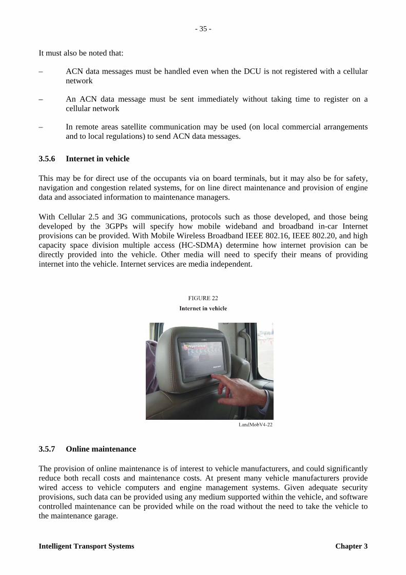
- 35 -
Intelligent Transport Systems Chapter 3
It must also be noted that:
– ACN data messages must be handled even when the DCU is not registered with a cellular network
– An ACN data message must be sent immediately without taking time to register on a cellular network
– In remote areas satellite communication may be used (on local commercial arrangements and to local regulations) to send ACN data messages.
3.5.6 Internet in vehicle
This may be for direct use of the occupants via on board terminals, but it may also be for safety, navigation and congestion related systems, for on line direct maintenance and provision of engine data and associated information to maintenance managers.
With Cellular 2.5 and 3G communications, protocols such as those developed, and those being developed by the 3GPPs will specify how mobile wideband and broadband in-car Internet provisions can be provided. With Mobile Wireless Broadband IEEE 802.16, IEEE 802.20, and high capacity space division multiple access (HC-SDMA) determine how internet provision can be directly provided into the vehicle. Other media will need to specify their means of providing internet into the vehicle. Internet services are media independent.
3.5.7 Online maintenance
The provision of online maintenance is of interest to vehicle manufacturers, and could significantly reduce both recall costs and maintenance costs. At present many vehicle manufacturers provide wired access to vehicle computers and engine management systems. Given adequate security provisions, such data can be provided using any medium supported within the vehicle, and software controlled maintenance can be provided while on the road without the need to take the vehicle to the maintenance garage.

- 36 -
Chapter 3 Intelligent Transport Systems
Such services benefit not only the vehicle user, but also enable vehicle manufacturers to download software improvements and reduce the number of vehicle recalls, which are not only expensive, but bad publicity for the manufacturer.
3.5.8 VMS in vehicle
Variable message signs (VMS) have become used in most developed countries. The infrastructure to keep these signs updated is already in place in most countries. However, the VMS message boards themselves are very expensive to build and maintain. Also they can create a visual intrusion in areas of natural beauty or in towns. Where vehicles are equipped with continuous communi-cations and a display screen, technologies can be used from the existing local ITS infrastructure, or simple broadcasting points established, to transmit VMS messages directly into the vehicle, providing a lower cost, and more up to date service.
3.5.9 Satellite navigation with congestion avoidance
There are already examples of satellite navigation systems that are being combined with congestion information using cellular technology, principally in Korea, and more recently in Europe (with services such as “TomTom GO”). These services currently use cellular communication, and may be expected to also use mobile wireless Broadband as this becomes deployed. As the communications related aspects of these services are data oriented, they can be provided by any medium supported in the vehicle. By using in vehicle Internet access, the cost of service provision can be significantly reduced while increasing value added potential to manufacturers and consumers.
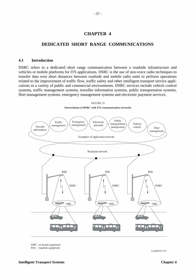
- 37 -
Intelligent Transport Systems Chapter 4
CHAPTER 4
DEDICATED SHORT RANGE COMMUNICATIONS
4.1 Introduction
DSRC refers to a dedicated short range communication between a roadside infrastructure and vehicles or mobile platforms for ITS applications. DSRC is the use of non-voice radio techniques to transfer data over short distances between roadside and mobile radio units to perform operations related to the improvement of traffic flow, traffic safety and other intelligent transport service appli-cations in a variety of public and commercial environments. DSRC services include vehicle control systems, traffic management systems, traveller information systems, public transportation systems, fleet management systems, emergency management systems and electronic payment services.

- 38 -
Chapter 4 Intelligent Transport Systems
The types of vehicle-roadside communication are generally spot, continuous, and wide-area. DSRC concerns the radio communication link of the spot type. DSRC is considered an effective technology for such systems as ETC (electronic toll collection) and navigation. DSRC systems have the following features:
– Restricted zone communications: communications possible only within restricted zones;
– Short-time communications: communications possible within restricted times.
The two major components of DSRC are on-board equipment (OBE) and roadside equipment (RSE).
On-board equipment (OBE): OBE is attached near the dashboard or on the windshield of the vehicle, and consists of radiocommunication circuits, an application processing circuit and so on. It usually has a human-machine interface, including switches, displays and buzzer.
Roadside equipment (RSE): RSE is installed above or alongside the road and communicates with passing OBE by use of radio signals. RSE consists of radiocommunication circuits, an application processing circuit and so on. It usually has a link to the roadside infrastructure to exchange data.
DSRC systems operate by transmitting radio signals for the exchange of data between vehicle mounted OBE and RSE. This exchange of data demands high reliability and user privacy as it may involve financial and other transactions.
Figure 25 shows the frequency bands used for DSRC in Europe, North America and Japan. With the exception of North America’s 900 MHz band (902-928 MHz), current use of frequency bands for each region is harmonized around 5.8 GHz ISM (industrial, scientific and medical) band.
This Handbook describes the outline of technologies and characteristics for DSRC in the 5.8 GHz band, complementing the contents of Recommendation ITU-R M.1453-2 – Intelligent transport systems – Dedicated short range communications at 5.8 GHz. There are two methods for DSRC

- 39 -
Intelligent Transport Systems Chapter 4
radiocommunication, the active (transceiver) method and the passive backscatter (transponder) method. Both methods, which have been used advantageously for existing DSRC-type services, are recommended in the Recommendation ITU-R M.1453-2 and described in this Handbook.
4.2 European DSRC system and applications
4.2.1 Background
In 1992, the CEPT (European Conference of Postal and Telecommunications Administrations)-ERC (European Radio communications Committee) agreed on ERC Decision (92)02 designating frequency bands for the development of a fully integrated road transport system in order to improve all aspects of road transport. It was decided to designate the frequency band 5 795-5 805 MHz on a european basis, with an additional sub-band 5 805-5 815 MHz on a national basis, to meet the requirements of multilane road junctions. The frequency bands were foreseen for initial road-to-vehicle systems, in particular for road toll systems for which requirements had emerged in a number of European countries at that time. In 2002, the Electronic Communications Committee (ECC) withdrew ERC Decision (92)02 and replaced it by ECC Decision (02)01, entering in force on 15 March 2002.
Based on the ECC Decision, standards for DSRC for ITS applications have been developed by European Committee for Standardization (CEN) and European Telecommunications Standards Institute (ETSI). A standard for the physical layer using microwaves at 5.8 GHz (CEN EN 12253) describes radiocommunication and RF parameter values necessary for co-existence and interop-erability of DSRC systems. This standard forms part of the DSRC family of standards consisting of four standards covering the protocol layers 1, 2 and 7 of the open systems interconnection (OSI) protocol stacks and profiles for RTTT (road transport and traffic telematics) applications. All these CEN standards were approved and published in 2003 and 2004.
The harmonized ETSI standard EN 300 674-2: dedicated short range communication (DSRC) transmission equipment (500 kbit/s/250 kbit/s) operating in the 5.8 GHz industrial, scientific and medical (ISM) band was approved and published in 2004. This standard contains general and environmental test conditions, methods of measurements and parameter limits.
The use of this harmonized ETSI standard gives a presumption of conformity to Article 3 of the Directive 1999/5/EC of the European Parliament and of the (R&TTE Directive).
4.2.2 Technical characteristics
4.2.2.1 Passive backscatter method
European DSRC systems adopt the passive backscatter (transponder) method. This method does not have an internal oscillator for generating a 5.8 GHz band radio carrier signal in the on board equipment (OBE), so it relies on the 5.8 GHz oscillator of the roadside unit with which it communicates. A detailed explanation is given in Fig. 26 with a typical functional block diagram.
As the passive transponder does not have a carrier signal oscillator, when transmitting from the OBE, the roadside unit has to emit an unmodulated carrier signal continuously. The OBE receives this signal, which is fed to the transmission circuit and makes it its own carrier signal (B). The transmission data from the main processing unit modulates the output of the sub-carrier signal oscillator C and mixes it with the carrier signal from the receiver. Resultant sideband signals carrying transmission data with different frequencies (carrier signal frequency plus/minus sub carrier frequency) from the carrier signal are transmitted with the carrier signal. The sub-carrier

- 40 -
Chapter 4 Intelligent Transport Systems
modulation method is utilized to extend the communication zone through reduction of the carrier phase noise and to reduce the re-use distance of RSE in passive transponder system. The modulated signal from the RSE is detected in the detector and processed by the main processing unit as receiving data. The communication zone of the passive (transponder) system is very small, typically up to 10 or 20 m in front of the RSE. To extend the communication zone to some degree, additional radio frequency amplifier D may be inserted into the transmission circuit of the transponder.
One of the significant features of the passive backscatter method is a narrow communication zone, typically up to 10 or 20 m in front of the RSE. This characteristic, i.e. communications can only take place at a precise point, is particularly important to correctly locate the vehicle. There are many applications utilizing this characteristic such as ETC, automatic vehicle identification (AVI) etc. Another feature of the passive backscatter method is that the structure of the OBE is simple and results in low manufacturing costs.
Figure 27 shows the RSE and OBE transmission timing chart and Fig. 28 shows the RSE and OBE transmission spectrum in passive backscatter method.

- 41 -
Intelligent Transport Systems Chapter 4
4.2.2.2 Technical characteristics of the European backscatter method
Technical characteristics of the European backscatter (transponder) method are shown in Table 5, which is an excerpt from Recommendation ITU-R M.1453-2. The Recommendation incorporates the “Medium data rate” European standard (CEN EN 12253) as well as the “High data rate” Italian standard into a single Recommendation.
TABLE 5
Characteristics of backscatter (transponder) method
(1) ERC Recommendation 70-03 specifies values of 2 W e.i.r.p. for active and 8 W e.i.r.p. for passive systems.
Technical characteristic Item
Medium data rate High data rate
Carrier frequencies 5.8 GHz band for downlink 5.8 GHz band for downlink Sub-carrier frequencies 1.5 MHz/2 MHz (uplink) 10.7 MHz (uplink) RF carrier spacing (channel separation)
5 MHz 10 MHz
Allowable occupied bandwidth Less than 5 MHz/channel Less than 10 MHz/channel Modulation method ASK (downlink carrier)
PSK (uplink sub-carrier) ASK (downlink carrier) PSK (uplink sub-carrier)
Data transmission speed (bit rate)
500 kbit/s (downlink) 250 kbit/s (uplink)
1 Mbit/s (downlink) 1 Mbit/s (uplink)
Data coding FM0 (downlink) NRZI (uplink)
Communication type Transponder type Transponder type Maximum e.i.r.p.(1) ≤ +33 dBm (downlink)
≤ –24 dBm (uplink: single sideband) ≤ +39 dBm (downlink) ≤ –14 dBm (uplink: single sideband)

- 42 -
Chapter 4 Intelligent Transport Systems
In the European DSRC standard, the OBE supports two kinds of sub-carrier frequencies (1.5 MHz and 2.0 MHz). Selection of sub-carrier frequency depends on the profile indicated by the RSE. (1.5 MHz is recommended). Frequency spectrum of “medium data rate” European standard is shown in Fig. 29.
In the case of “high data rate” Italian standard, the OBE uplink sub-carrier frequency is 10.7 MHz, resulting in higher uplink data transmission speed.
Frequency spectrum of the “high data rate” Italian standard is shown in Fig. 30.

- 43 -
Intelligent Transport Systems Chapter 4
4.2.3 Applications
4.2.3.1 General
A large number of European countries are implementing ETC system based on DSRC technology. ETC applications are considered to be a major driving force that will create the new market for a large number of DSRC equipment which provides the versatile services for other DSRC based applications. In addition to ETC, applications such as access control, parking management and payment, traffic information and emergency warning, freight and fleet management, traffic control etc. are proposed as ITS services in Europe. These applications are expected to be implemented significantly when ETC using DSRC technology becomes widely used.
The European project DELTA (DSRC electronics implementation for transportation and automotive applications) is aiming to integrate the DSRC communication link as basic equipment in any vehicle. The following list includes such possible future ITS applications:
– In-vehicle signing to assist for safe driving (obtaining roadside traffic and travel information)
– Parking garage fee payment
– MP3 music download while fuelling
– Vehicle status for car rental automatic billing
– Software installation (service facility installs fleet management software on the vehicle)
– Mission planning (a fleet operator plans and downloads mission data to the vehicle)
– Floating car data (acquisition of travel-related information via DSRC)
– Multimodal transport information (display of public transport vehicle information)
– Vehicle control (adaptive automatic cruise control)
– Service subscription
– Diagnostics (service technician diagnostics fault via DSRC).
It should be noted, that for many of these services, there are competing technologies e.g. mobile communications with satellite positioning (GNSS). However, the specific characteristics of DSRC such as high data integrity (highly reliability) and low transmission latency (real time) will make it possible for DSRC to be used for most services associated with these applications.
Typical applications utilizing favourable characteristics of passive DSRC are described below. These applications are standardized within the European Committee for Standardization (CEN).
4.2.3.2 Electronic toll collection (ETC)
Electronic toll collection (ETC), also known as electronic fee collection (EFC), using DSRC is a forerunner of ITS applications in many European countries. ETC can reduce traffic congestion at toll plazas by allowing non-stop driving through a toll gate. As a vehicle passes through the toll gate, a roadside antenna communicates with the OBE (transponder) generally located on the inside of the car’s windscreen/windshield. Vehicles are charged automatically as they pass through the toll gates (see Fig. 31).

- 44 -
Chapter 4 Intelligent Transport Systems
DSRC, in conjunction with the related equipment such as sensor system to detect the presence of a vehicle, can perform three fundamental functions of ETC i.e. locating the vehicle, communication with the vehicle and enforcement for the fraudulent vehicles.
The number of ETC subscribers in Europe is estimated to be more than ten million as of March 2005. In Italy (almost 5 million subscribers), Portugal (nearly 2 million), France (almost 2 million) and Norway (more than 1 million) ETC systems are used almost on a nationwide basis as the means of collecting highway tolls.
ETC applications are being standardised in CEN TC278 in collaboration with ISO TC204. One of the most important deliverables is ISO 14906 – Electronic fee collection – Application interface definition for dedicated short-range communication.
4.2.3.3 Electronic registration identification (ERI)
Electronic Registration Identification (ERI) is a means of wirelessly collecting registration and other related data, including highly encrypted secure data. The external ERI reader is used to read data from the ERI tag on the vehicle (see Fig. 32).
The application of ERI will offer significant benefits over existing technologies for vehicle identification. The vehicle identification data consists of the vehicle identifier e.g. VIN (vehicle identification number) and may also include additional vehicle data as typically included in a vehicle registration certificate. ERI will be an enabling technology for the future management and administration of traffic and transport. ERI is required for the need of authorities and other users to realize a trusted electronic identification.

- 45 -
Intelligent Transport Systems Chapter 4
4.2.3.4 Medium range pre-information (MRPI)
Medium range pre-information (MRPI) via DSRC is a bi-directional communication system which disseminates traffic and travel information based on the various sources of information available. It also retrieves information collected from vehicles at the different RSE sites.
- 46 -
Chapter 4 Intelligent Transport Systems
The communication zone of DSRC does not exceed some 10 or 20 m in front of the RSE. At the time of communication, the position of the vehicle on a particular road is accurately known not only in terms of geographical localization but in terms of road and travel direction. Even when the vehicle is beyond the communication zone, by combining initial location information with information from the vehicle’s speed sensor or odometer, the position of the vehicle is known with great accuracy for several kilometres and with reasonable accuracy for tens of kilometres. Location information is updated when the vehicle passes the next RSE.
For simple applications, the information transmitted by a vehicle defines a status change characteristic or event and the distance from the last known reference point of delivery to this characteristic or event. Information such as average speed data, location of fog, heavy rain, and slippery roads etc. can be also retrieved from vehicles. This information provides valuable floating car data for road network managers and subsequently, a warning to the following traffic.
4.3 Japanese DSRC system and applications
4.3.1 Background
In July 1996, the comprehensive plan for ITS in Japan was structured to promote ITS as a long term vision. It illustrates the proposed functions of ITS and the basic concepts of development and deployment for Japan. This plan defines twenty ITS user services and establishes goals for research, development and deployment by public, academic and industrial sectors, categorized into nine development areas. Electronic toll collection system (ETC) is categorized as one of the nine development areas.
DSRC is a key technology for ETC and various other ITS application services. In 1994, development for DSRC started in the Telecommunications Technology Council, established by the Ministry of Posts and Telecommunications (now Ministry of Internal Affairs and Communications). In 1997, in accordance with the report from the Telecommunications Technology Council, the Ministry of Posts and Telecommunications published the regulation on DSRC (for ETC). In November 1997, the DSRC standard was established and published by ARIB (Association of Radio Industries and Businesses) in Japan.
In 1994, the Japanese Ministry of Construction (now Ministry of Land, Infrastructure and Transport), in cooperation with four major public toll operators and ten consortiums consisting of private companies, started a joint research project on electronic toll collection (ETC) systems which have nationwide interoperability in Japan. The research was completed by the test operation conducted on the Odawara – Atsugi highway in 1997.
In 2001, ETC services started across the nation. As of July 2006, the number of ETC subscribers reached 13 million. Increasing the number of subscribers will allow for various applications to be served by DSRC technology using the same OBE.

- 47 -
Intelligent Transport Systems Chapter 4
4.3.2 Technical characteristics
4.3.2.1 Active (transceiver) method
The Japanese DSRC system adopts the active (transceiver) method. For the active (transceiver) method, the OBE is equipped with the same functions as RSE which is equipped with devices necessary for radiocommunication. More specifically, both RSE and OBE incorporate a 5.8 GHz band carrier frequency oscillator and have the same functionality for radio transmission. Figure 34 shows a typical block diagram for the OBE’s radio circuitry. The upper half of Fig. 34 is the receiver, the lower half is the transmitter and the processing unit is to the right. The transmission and reception antennas may be shared. The OBE in the active (transceiver) method receives radio signals from the RSE with the antenna on the upper left. Each signal received passes through each functional block and is processed by the main processing unit as reception data. The transmission signal from the OBE is the 5.8 GHz band carrier signal from oscillator A modulated with transmission data. The signal is sent from the antenna on the bottom left.
The active (transceiver) method can easily realize small or large communication zones by control-ling the directivity of transmission antenna. Figure 35 shows examples of flexible communication zones forming in the typical configuration of the ETC gate. The footprint (communication zone) of an ETC antenna is very small (typically 3 m × 4 m). On the other hand, a large footprint of up to 30 m in length can be realized by approach antenna for information dissemination. The bit error rate (BER) within the footprints is very low (less than 10–6). The main feature of the active (transceiver) method is a flexible zone forming, in addition to large volumes of information to be communicated with high reliability. These characteristics are indispensable for various ITS application services using DSRC.

- 48 -
Chapter 4 Intelligent Transport Systems
4.3.2.2 Technical characteristics of the Japanese active method
Technical characteristics of the Japanese active (transceiver) method are shown in Table 6, which is also an excerpt from Recommendation ITU-R M.1453-2. In this table there are two specifications in RF carrier spacing column. Wide spacing (10 MHz channel separation) is mainly for current ETC application with the ASK (amplitude shift keying) modulation method. Narrow spacing (5 MHz channel separation) is for multi purpose DSRC application services with the ASK and/or QPSK modulation method. Specifications for the narrow spacing was added in October 2000, when the Japanese Ministry of Posts and Telecommunications (now MIC) revised the radio law according to the proposal of the Telecommunications Technology Council on general purpose DSRC system applications. The revision was proposed to and adopted by the ITU-R as the modified DSRC Recommendation ITU-R M.1453-1 in August 2002.
The maximum communication zone of DSRC is recommended to be within 30 m to promote effective use of frequencies by reducing the re-use distance of RSE. FDD systems are also adopted to promote effective use of radio frequencies.
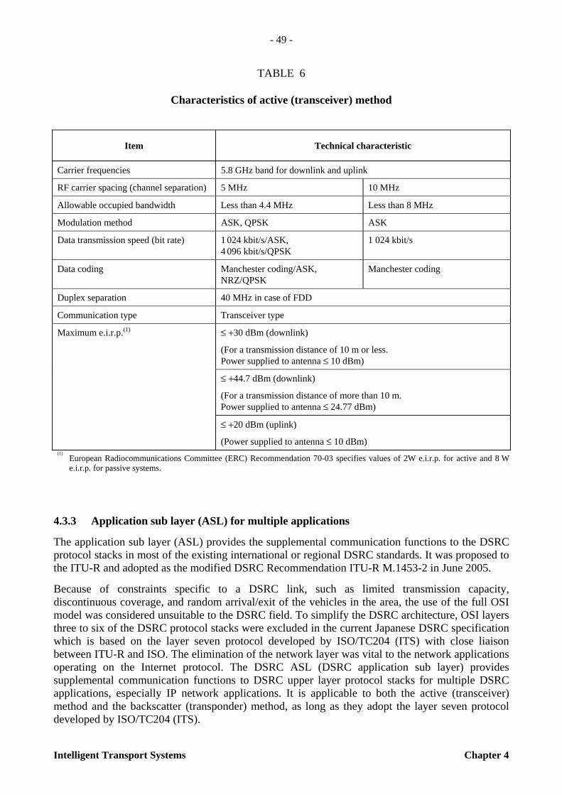
- 49 -
Intelligent Transport Systems Chapter 4
TABLE 6
Characteristics of active (transceiver) method
4.3.3 Application sub layer (ASL) for multiple applications
The application sub layer (ASL) provides the supplemental communication functions to the DSRC protocol stacks in most of the existing international or regional DSRC standards. It was proposed to the ITU-R and adopted as the modified DSRC Recommendation ITU-R M.1453-2 in June 2005.
Because of constraints specific to a DSRC link, such as limited transmission capacity, discontinuous coverage, and random arrival/exit of the vehicles in the area, the use of the full OSI model was considered unsuitable to the DSRC field. To simplify the DSRC architecture, OSI layers three to six of the DSRC protocol stacks were excluded in the current Japanese DSRC specification which is based on the layer seven protocol developed by ISO/TC204 (ITS) with close liaison between ITU-R and ISO. The elimination of the network layer was vital to the network applications operating on the Internet protocol. The DSRC ASL (DSRC application sub layer) provides supplemental communication functions to DSRC upper layer protocol stacks for multiple DSRC applications, especially IP network applications. It is applicable to both the active (transceiver) method and the backscatter (transponder) method, as long as they adopt the layer seven protocol developed by ISO/TC204 (ITS).
Item Technical characteristic
Carrier frequencies 5.8 GHz band for downlink and uplink
RF carrier spacing (channel separation) 5 MHz 10 MHz
Allowable occupied bandwidth Less than 4.4 MHz Less than 8 MHz
Modulation method ASK, QPSK ASK
Data transmission speed (bit rate) 1 024 kbit/s/ASK, 4 096 kbit/s/QPSK
1 024 kbit/s
Data coding Manchester coding/ASK, NRZ/QPSK
Manchester coding
Duplex separation 40 MHz in case of FDD
Communication type Transceiver type
≤ +30 dBm (downlink)
(For a transmission distance of 10 m or less. Power supplied to antenna ≤ 10 dBm)
≤ +44.7 dBm (downlink)
(For a transmission distance of more than 10 m. Power supplied to antenna ≤ 24.77 dBm)
Maximum e.i.r.p.(1)
≤ +20 dBm (uplink)
(Power supplied to antenna ≤ 10 dBm) (1)
European Radiocommunications Committee (ERC) Recommendation 70-03 specifies values of 2W e.i.r.p. for active and 8 W e.i.r.p. for passive systems.
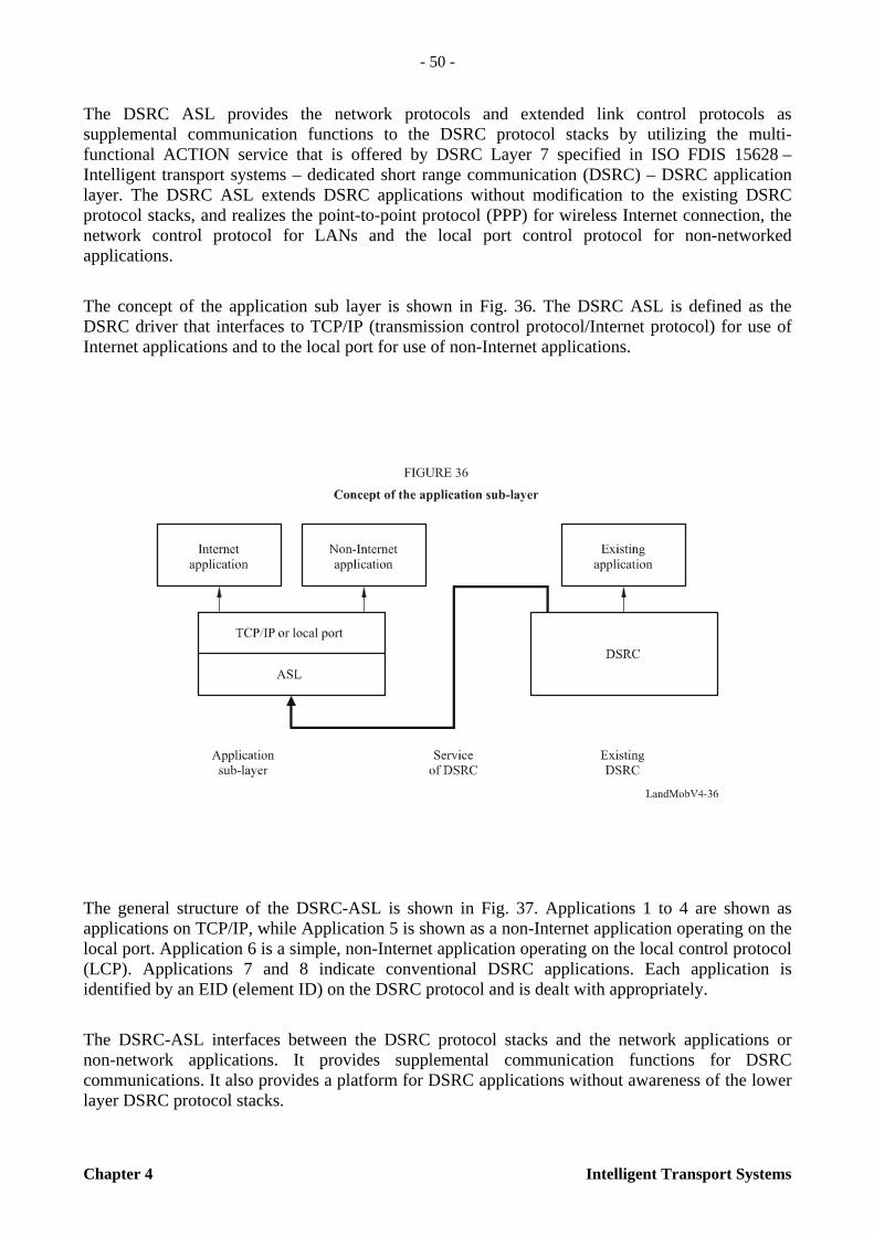
- 50 -
Chapter 4 Intelligent Transport Systems
The DSRC ASL provides the network protocols and extended link control protocols as supplemental communication functions to the DSRC protocol stacks by utilizing the multi-functional ACTION service that is offered by DSRC Layer 7 specified in ISO FDIS 15628 – Intelligent transport systems – dedicated short range communication (DSRC) – DSRC application layer. The DSRC ASL extends DSRC applications without modification to the existing DSRC protocol stacks, and realizes the point-to-point protocol (PPP) for wireless Internet connection, the network control protocol for LANs and the local port control protocol for non-networked applications.
The concept of the application sub layer is shown in Fig. 36. The DSRC ASL is defined as the DSRC driver that interfaces to TCP/IP (transmission control protocol/Internet protocol) for use of Internet applications and to the local port for use of non-Internet applications.
The general structure of the DSRC-ASL is shown in Fig. 37. Applications 1 to 4 are shown as applications on TCP/IP, while Application 5 is shown as a non-Internet application operating on the local port. Application 6 is a simple, non-Internet application operating on the local control protocol (LCP). Applications 7 and 8 indicate conventional DSRC applications. Each application is identified by an EID (element ID) on the DSRC protocol and is dealt with appropriately.
The DSRC-ASL interfaces between the DSRC protocol stacks and the network applications or non-network applications. It provides supplemental communication functions for DSRC communications. It also provides a platform for DSRC applications without awareness of the lower layer DSRC protocol stacks.

- 51 -
Intelligent Transport Systems Chapter 4
4.3.4 Applications
4.3.4.1 General
As in Europe, electronic toll collection (ETC) using DSRC is a forerunner of ITS applications in Japan. ETC service in Japan started in March 2001 and by the end of March 2003, the service covered approximately 900 toll gates through which 90% of expressway users pass. This indicates that the service was deployed nationwide in approximately two years. As of the end of March 2004, the number of toll gates increased to 1 300 and as of July 2006, the number of OBEs (ETC subscribers) reached thirteen million.
The rapid increase in ETC subscribers provides for favourable conditions for various applications to be served by DSRC technology using the same OBE. Research and development are underway through cooperation between the public and industries to develop multiple-purpose on-board equipment that realizes a variety of DSRC services.
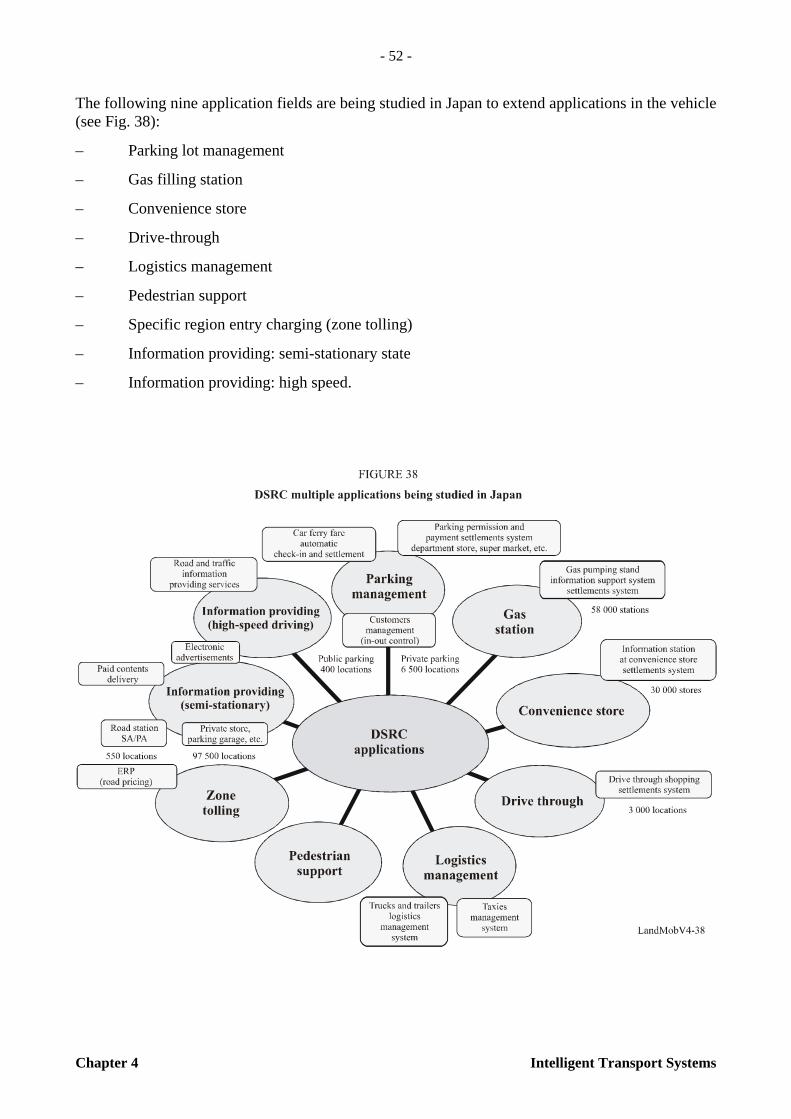
- 52 -
Chapter 4 Intelligent Transport Systems
The following nine application fields are being studied in Japan to extend applications in the vehicle (see Fig. 38):
– Parking lot management
– Gas filling station
– Convenience store
– Drive-through
– Logistics management
– Pedestrian support
– Specific region entry charging (zone tolling)
– Information providing: semi-stationary state
– Information providing: high speed.

- 53 -
Intelligent Transport Systems Chapter 4
4.3.4.2 Electronic toll collection (ETC)
Toll road service providers in Japan (Japan Highways, Metropolitan Express Ways, Hanshin Express Ways, Honshu-Shikoku Bridges, etc.) were already providing nationwide toll road services with manual toll collection before ETC was developed. ETC alleviates traffic congestion at toll gates, enhances convenience for drivers by eliminating the need to handle cash and reduces management cost. The ETC system in Japan must handle the complicated system of tolls in which different amounts are charged according to the type of vehicle and distance travelled. Furthermore, a single vehicle’s on-board equipment (OBE) must be used on numerous toll roads managed by different administrative bodies.
When ETC was developed, the following were set as the features of the ETC specification in Japan:
– Nationwide interoperable system.
– Adoption of 5.8 GHz-band active DSRC system to ensure highly reliable two-way communication between the vehicles and roadside equipment.
– Adoption of the “Two-piece” OBE composed of an OBU (On board unit) and an IC card for future functional extension and for multi-purpose use of IC cards.
– Adoption of highly secure system to prevent fraudulent use.
Figure 39 shows the basic configuration of Japanese ETC gate. An IC card containing contract information is inserted into an on-board unit (OBU) mounted inside a vehicle. This on-board unit communicates with the roadside antenna at the tollgate through two-way radio communication (DSRC). Highway tolls and other items of information are recorded on both the IC card and a toll road computer connected to the roadside antenna. The drivers can pass through the tollgate without stopping the vehicle.
FIGURE 39
Basic configuration of Japanese ETC (http://www.mlit.go.jp/road/ITS)

- 54 -
Chapter 4 Intelligent Transport Systems
4.3.4.3 Basic application interface to extend application in vehicles
While DSRC is widely expanding over electronic toll collection systems, applying DSRC to other services, especially to non-networks applications in vehicles such as charge payment settlement using IC card and information providing services to high speed vehicles, has been requested. In order to easily apply DSRC to these non-networks applications, command sets for remote devices control using the DSRC-ASL, so called “basic application interface” are being developed. The basic application interface is for non-network applications providing application services in non-Internet circumstance, and realizes ITS services by remote-accessing OBE in accordance with service contents.
The basic application interface is inserted between local port control protocol of application sub layer and non-network applications, and controls the resources of on board equipment (OBE) in vehicles from road side equipment (RSE). The basic application interface defines “command sets” and provides facilities to access remote devices on OBE in vehicles. By choosing appropriate command sets and combining these command sets, non-networks local applications conduct their application transactions between roadside applications and in-vehicle applications efficiently.
Some examples of command sets in basic application interface are listed below:
– OBE indications/response application for OBE Human Machine Interface
– OBE memory access application for writing/reading of the OBE memory from RSE
– IC card access application for billing and settlement of IC cards
– Push type information delivery application for delivering packaged information from RSE to OBE.
Figure 40 shows an example of basic application interface.
4.4 ITS system using DSRC network
4.4.1 Introduction
In the fall of 2000, the Korean Ministry of Construction and Transportation (MOCT) announced that the areas of Daejeon, Jeju and Jeonju were chosen to showcase deployment of ITS. The program, called the advanced transportation systems deployment initiatives, makes a significant step in intelligent transportation infrastructure (ITI) in Korea. The program calls for public and private sector partners to develop and integrate ITS technology to reduce travel times, improve emergency response and provide travel information to the public.
In Korea, demand for transportation facilities and services far outweighs the supply. Although most urban areas face this challenge, the problem is especially acute in Korea because of rapid growth in population and employment. Analysis has shown that unless the government takes action to make improvements, transportation system performance will decline dramatically over the next 20 years.
4.4.2 Model deployment initiatives
The MOCT solicited bids from cities around the nation to receive funding as part of an ITS deployment initiative. This initiative would help fund the development of fully integrated ITIs in selected cities in Korea.
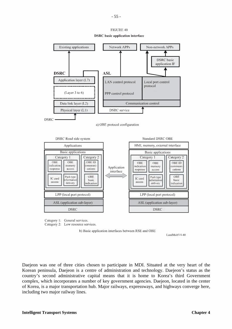
- 55 -
Intelligent Transport Systems Chapter 4
Daejeon was one of three cities chosen to participate in MDI. Situated at the very heart of the Korean peninsula, Daejeon is a centre of administration and technology. Daejeon’s status as the country’s second administrative capital means that it is home to Korea’s third Government complex, which incorporates a number of key government agencies. Daejeon, located in the center of Korea, is a major transportation hub. Major railways, expressways, and highways converge here, including two major railway lines.
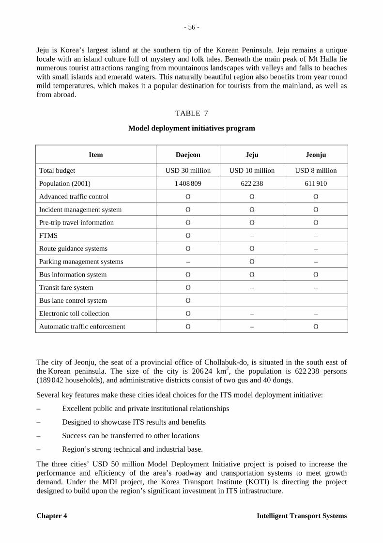
- 56 -
Chapter 4 Intelligent Transport Systems
Jeju is Korea’s largest island at the southern tip of the Korean Peninsula. Jeju remains a unique locale with an island culture full of mystery and folk tales. Beneath the main peak of Mt Halla lie numerous tourist attractions ranging from mountainous landscapes with valleys and falls to beaches with small islands and emerald waters. This naturally beautiful region also benefits from year round mild temperatures, which makes it a popular destination for tourists from the mainland, as well as from abroad.
TABLE 7
Model deployment initiatives program
The city of Jeonju, the seat of a provincial office of Chollabuk-do, is situated in the south east of the Korean peninsula. The size of the city is 206 24 km2, the population is 622 238 persons (189 042 households), and administrative districts consist of two gus and 40 dongs.
Several key features make these cities ideal choices for the ITS model deployment initiative:
– Excellent public and private institutional relationships
– Designed to showcase ITS results and benefits
– Success can be transferred to other locations
– Region’s strong technical and industrial base.
The three cities’ USD 50 million Model Deployment Initiative project is poised to increase the performance and efficiency of the area’s roadway and transportation systems to meet growth demand. Under the MDI project, the Korea Transport Institute (KOTI) is directing the project designed to build upon the region’s significant investment in ITS infrastructure.
Item Daejeon Jeju Jeonju
Total budget USD 30 million USD 10 million USD 8 million
Population (2001) 1 408 809 622 238 611 910
Advanced traffic control O O O
Incident management system O O O
Pre-trip travel information O O O
FTMS O – –
Route guidance systems O O –
Parking management systems – O –
Bus information system O O O
Transit fare system O – –
Bus lane control system O
Electronic toll collection O – –
Automatic traffic enforcement O – O

- 57 -
Intelligent Transport Systems Chapter 4
4.4.2.1 Key program elements
The program consists of six sub-systems including a traveller information system, a transit management & information system, an automated enforcement system, a traffic signal control and an incident management system.
The transit management system, with advanced vehicle location systems using GPS and DSRC technology on 965 transit vehicles, improves their on-time performance and provides real-time information on bus schedule status. Electronic messages at bus stops inform riders of the location of their buses. An Internet site and kiosks at transit centres also provide riders with information on bus routes, schedules, traffic conditions and trip planning information. As part of the project, electronic fare payment is deployed. Transit cards based on smart card technology are used for payment on buses and subways and include other useful functions.
Advanced traffic signal control systems called COSMOS can enhance signal timing to better manage traffic demands. The incident management system, with a surveillance system, helps local agencies respond to incidents rapidly and effectively.
The traveller information system with DSRC based real-time traffic information system enables the public to make informed transportation choices. The automated traffic enforcement system is used for the automated enforcement of speed and signal violations.
These programs also provide input to national marketing materials, creating brochures and other documents to aid the transfer process. The public relations and marketing effort particularly focused on the benefits of multimodal traveller information systems should raise the level of ITS awareness in Korea.
4.4.2.2 Project management
The MDI has drawn its staffing from the partners who comprise the partnership. The Korea Transport Institute (KOTI), The Korea Research Institute of Human Settlements (KRIHS) and Korea Institute of Construction Technology (KICT) were assigned to manage the project in Daejeon, Jeonju and Jeju, respectively. Additional staff members from these agencies, as well as individuals from the partnering cities were also asked to join the team.

- 58 -
Chapter 4 Intelligent Transport Systems
4.4.3 Active DSRC
In ITS, there is increasing use of dedicated roadside communications based on DSRC technology. DSRC is different from other mobile communications systems, as it can transmit the data up to 1 Mbit/s within a limited area. The active type of DSRC systems is deployed for traffic information and transit management systems. It will also be deployed in parking control systems and electronic toll collection.
TABLE 8
DSRC major specification
About 5 000 probe cars and buses will provide their location and time that they pass RSEs, and the RSEs will then send the data to the traffic management center using an ADSL communication line. Specifications for DSRC are used in the Daejeon ITS model deployment project.
TABLE 9
Characteristics of equipment
Item Specifications
Frequency band 5.8 GHz
Carrier frequency interval 10 MHz
Modulation method ASK
Data transfer rate 1 Mbit/s
Protocol Slotted ALOHA
Antenna power RSE/OBE 10 MW
Active DSRC roadside equipment (RSE) On board unit (OBU)
Physical appearance
Dimension 160 mm × 210 mm × 80 mm 110 mm × 100 mm × 45 mm
Weight 3.5 kg 0.3 kg
Power source AC 85V ~ AC 265V DC 12V / 24V

- 59 -
Intelligent Transport Systems Chapter 4

- 60 -
Chapter 4 Intelligent Transport Systems
4.5 Future trends: 5.9 GHz DSRC system and applications
4.5.1 Introduction
While current DSRC communications will have an important role for many ITS user services, longer range and higher capacity communication than the current capability of DSRC devices are being requested for next generation ITS radiocommunication. Applications of the next generation ITS radiocommunication will require longer range vehicle and driver safety communications, higher capacity info-communications, etc.
The introduction of such services will provide the following benefits:
– Transportation, administrative and police authorities could monitor, manage, and control vehicles and pedestrians;
– Drivers and pedestrians could be supported safely and comfortably while driving and travelling, thus establishing a new culture which integrates wireless communication and transportation;
– The transportation industry, including road managers, commercial vehicle operators, bus companies, etc. could have the most powerful tools for efficient operation and maintenance.
In July 2004, the US Federal Communications Commission (FCC) adopted licensing and service rules for the dedicated short range communications service (DSRCS) in the ITS radio service in the 5.9 GHz band to promote a nationwide solution to the transportation safety. On-board units of the DSRCS shall comply with the technical standards of ASTM (American Society for Testing and Materials, later ASTM International) E2213–03, standard specification for telecommunications and information exchange between roadside and vehicle systems; 5 GHz band DSRC medium access control (MAC) and physical layer (PHY) specifications published September 2003. The technical standard of (ASTM) E2213–03 suggests that the DSRCS is considered a next generation radiocommunication service.
4.5.2 Functional requirements of next generation ITS radiocommunication systems
Figure 44 shows mapping of candidate applications of the next generation ITS radiocommunication system in terms of mobility and data transmission rate, under extensive study in ITU-R. The functional requirements for next generation ITS radiocommunication should support more than 3 Mbit/s of channel transmission rate. A communication and/or broadcasting range up to 1 km may be required for certain applications. An initial attempt to define such functional requirements is summarized as follows:
a) Basic configuration
– A system consisting of RSE, an integrated OBE for vehicular applications and/or personal communications devices (PCD), and radiocommunication links among them.
– A single OBE or PCD needs to handle multiple applications.
– The OBE or PCD needs to be flexible enough to accommodate various user needs.
– Easy access to RSE and OBE for the introduction of versatile services.
– Providing operation and maintenance functions.
– Providing several network access interfaces (e.g. LAN, ADSL, DSL, FWA, IMT 2000 and beyond, etc.).

- 61 -
Intelligent Transport Systems Chapter 4
b) Technical characteristics and radiocommunication issues
– 3 to 5 Mbit/s transmission rate is appropriate to accommodate most applications.
– Bandwidth requirements: 10 MHz.
– BER: 10–5 – 10–6.
– Fast initialization time: under 1 ms.
– Frequency use: TDD (optionally FDD).
– Communication mode: point-to-point, simple broadcasting, and multicasting according to services.
– Connection mode: OBE to RSE, OBE to OBE, and RSE to RSE connections for exchanging of information and/or maintenance data.
– Communications cell size needs to be flexible in accordance with the anticipated applications.
– Providing tolerance against interference.
- 62 -
Chapter 4 Intelligent Transport Systems
– Handover function: handover for adjacent zone or isolated zone.
– Priority control: high, moderate, and low priority according to requested user services and user classification.
– Appropriate security functions for each user service.
c) Maximum vehicle speed
– The radio link needs to provide services to a vehicle with a maximum speed of 200 km/h.
– High-speed rail applications may have stricter requirements.
d) Operating environment
– Roadside environment: narrow/wide road surrounded by low/high rise buildings, etc.
– Open-area environment.
– Indoor environment.
e) Other considerations
– Various functions, such as electronic transactions, need to be provided according to the needs of users and information providers.
– Competitive communication equipment cost.
– For radio interface operation, the required frequency planning and necessary inter-network coordination should be kept to a minimum.
4.5.3 Requirements for the radio transmission technology
To satisfy functional requirements for next generation ITS radiocommunication, effective radio transmission technology should be employed. An important first step is to investigate the characteristics of DSRC radio propagation to enable DSRC system designs that operate for efficient frequency use and robustness to interference in applications.
4.5.3.1 Characteristics of DSRC radio propagation
In DSRC radio propagation, ground reflection is the most important element to determine the reception characteristics at the receiver. Figure 45, called the two-ray propagation model shows the relationship between the direct and reflected paths and an example of reception level at the receiver in distance. The direct and ground-reflected waves may increase or decrease the reception level, depending on the difference (∆r = 2 hT hR /d ) between the lengths of the direct and reflected paths. Since the direct and ground-reflected waves interfere constructively or destructively depending on the phase relation between the reflected and direct wave, reception level at the receiver changes remarkably up to the break point (dBP = (4 hT hR )/λ, where λ is the wavelength) from where the reflected wave begins to cancel the direct wave permanently and the reception level decays more rapidly (1/d
4 ) than the free space level (1/d
2 ).

- 63 -
Intelligent Transport Systems Chapter 4
Three areas, characterized by the distance between transmitter and receiver, are recognized:
Area 1: Up to several tens of meters (typically up to 30 m).
Though theoretical reception level at the receiver changes with distance by the ground reflection, it can be mostly neglected, thanks to the directivity of the transmitter and receiver antenna. This area is most suited for DSRC applications.
Area 2: From several tens of meters up to the break point.
Reception level at the receiver changes remarkably with distance and the vehicles moving along the roadway experience rapid fading.
Area 3: Beyond the break point.
Reception level decays rapidly (1/d 4
). Vehicles moving along the roadway are subject to most severe interference.

- 64 -
Chapter 4 Intelligent Transport Systems
4.5.3.2 Considerations for DSRC propagation environment
Besides the characteristics of the two-ray propagation model described above, the following interference factors must be considered in an actual DSRC environment:
Multipath fading: Multipath propagation due to scattering and reflection from the ground, buildings and other vehicles leads to rapid fading in high speed vehicles.
Delay spread: When digital information to be sent is at a high data rate, the delay spread effects (distortion caused by time dispersion introduced by multipath channels) must be considered.
Shadowing: Diffraction loss due to shadowing by large obstacles such as a bus causes a significant field-strength attenuation.
Doppler effects: Particularly at high frequencies and at high vehicle speed, the Doppler effects (distortion caused by frequency dispersion due to Doppler effects) may be considered.
4.5.3.3 Technology for next generation ITS radiocommunication
Next generation ITS radiocommunication requires medium to long range transmission (Areas 2 and 3) with a high data rate in contrast to the conventional DSRC with short range transmission (Area 1) and medium data rate. In the medium to long-range transmission, effective radio transmission technology should be employed for efficient frequency use and robustness to interference described above. One of the favourable technologies for next generation ITS radio-communication is OFDM.
An example of the schematic diagram of OFDM modulation is shown in Fig. 47. The basic principle of OFDM is to split a high rate data stream into a number of lower rate data streams transmitted simultaneously over a number of orthogonal sub-carriers. Each sub-carrier is independently modulated commonly using some type of quadrature amplitude modulation (QAM) or phase-shift keying (PSK). This composite baseband signal is used to modulate a main radio frequency carrier. The benefits of using OFDM include high spectrum efficiency, resistance against multipath interference, particularly against the delay spread effects, and ease of filtering out noise.
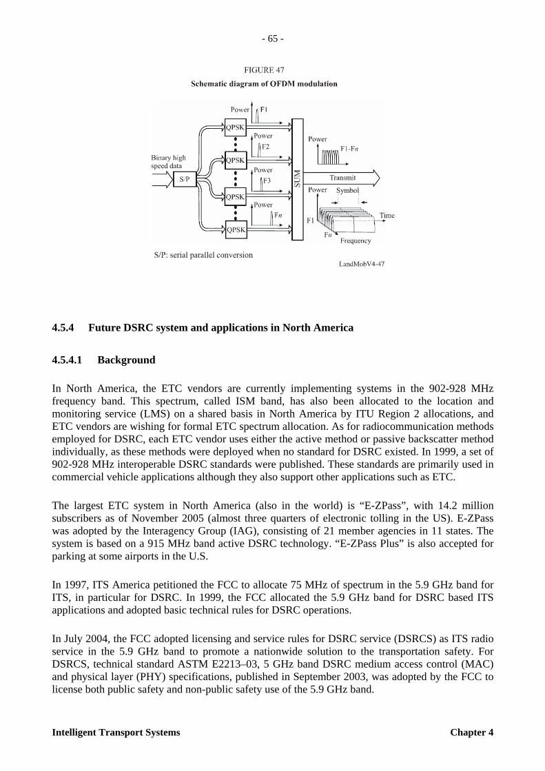
- 65 -
Intelligent Transport Systems Chapter 4
4.5.4 Future DSRC system and applications in North America
4.5.4.1 Background
In North America, the ETC vendors are currently implementing systems in the 902-928 MHz frequency band. This spectrum, called ISM band, has also been allocated to the location and monitoring service (LMS) on a shared basis in North America by ITU Region 2 allocations, and ETC vendors are wishing for formal ETC spectrum allocation. As for radiocommunication methods employed for DSRC, each ETC vendor uses either the active method or passive backscatter method individually, as these methods were deployed when no standard for DSRC existed. In 1999, a set of 902-928 MHz interoperable DSRC standards were published. These standards are primarily used in commercial vehicle applications although they also support other applications such as ETC.
The largest ETC system in North America (also in the world) is “E-ZPass”, with 14.2 million subscribers as of November 2005 (almost three quarters of electronic tolling in the US). E-ZPass was adopted by the Interagency Group (IAG), consisting of 21 member agencies in 11 states. The system is based on a 915 MHz band active DSRC technology. “E-ZPass Plus” is also accepted for parking at some airports in the U.S.
In 1997, ITS America petitioned the FCC to allocate 75 MHz of spectrum in the 5.9 GHz band for ITS, in particular for DSRC. In 1999, the FCC allocated the 5.9 GHz band for DSRC based ITS applications and adopted basic technical rules for DSRC operations.
In July 2004, the FCC adopted licensing and service rules for DSRC service (DSRCS) as ITS radio service in the 5.9 GHz band to promote a nationwide solution to the transportation safety. For DSRCS, technical standard ASTM E2213–03, 5 GHz band DSRC medium access control (MAC) and physical layer (PHY) specifications, published in September 2003, was adopted by the FCC to license both public safety and non-public safety use of the 5.9 GHz band.
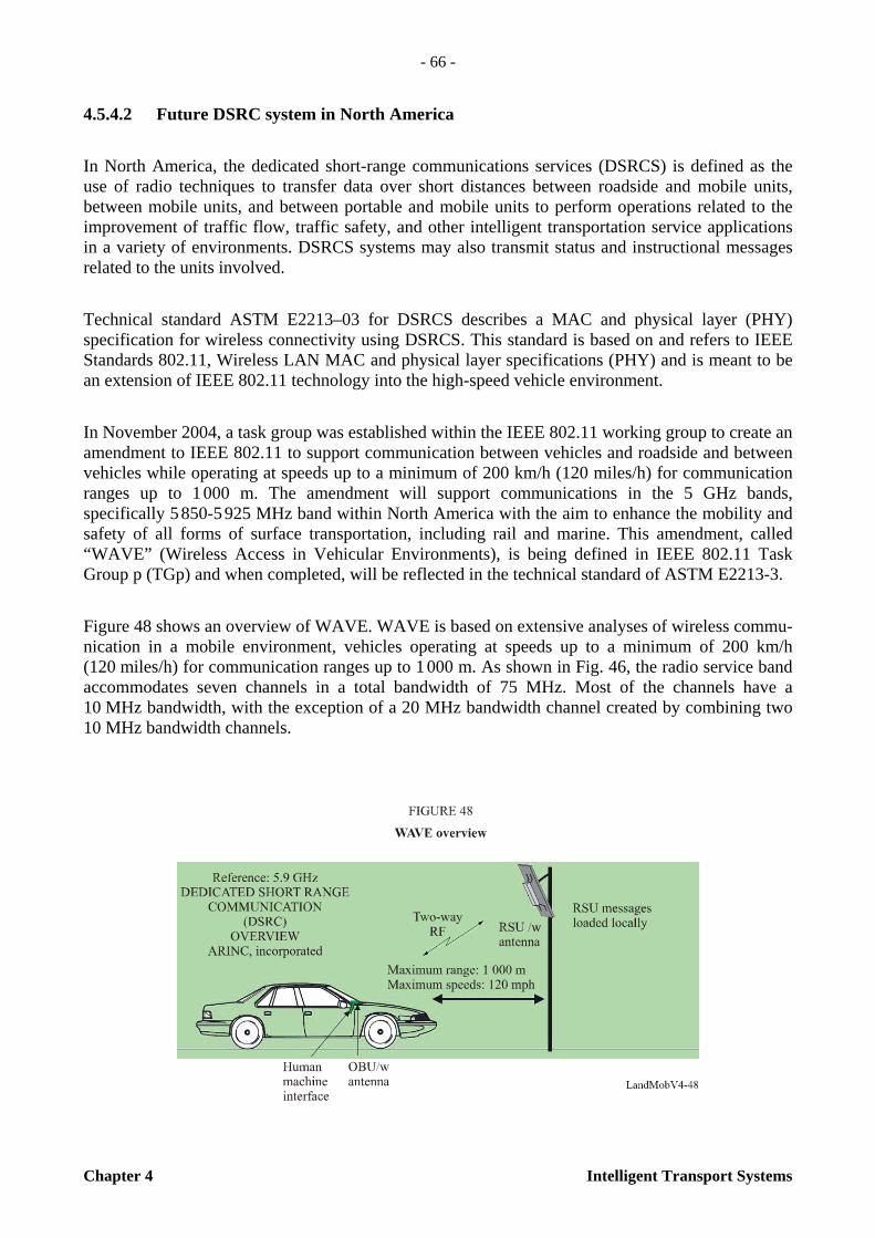
- 66 -
Chapter 4 Intelligent Transport Systems
4.5.4.2 Future DSRC system in North America
In North America, the dedicated short-range communications services (DSRCS) is defined as the use of radio techniques to transfer data over short distances between roadside and mobile units, between mobile units, and between portable and mobile units to perform operations related to the improvement of traffic flow, traffic safety, and other intelligent transportation service applications in a variety of environments. DSRCS systems may also transmit status and instructional messages related to the units involved.
Technical standard ASTM E2213–03 for DSRCS describes a MAC and physical layer (PHY) specification for wireless connectivity using DSRCS. This standard is based on and refers to IEEE Standards 802.11, Wireless LAN MAC and physical layer specifications (PHY) and is meant to be an extension of IEEE 802.11 technology into the high-speed vehicle environment.
In November 2004, a task group was established within the IEEE 802.11 working group to create an amendment to IEEE 802.11 to support communication between vehicles and roadside and between vehicles while operating at speeds up to a minimum of 200 km/h (120 miles/h) for communication ranges up to 1 000 m. The amendment will support communications in the 5 GHz bands, specifically 5 850-5 925 MHz band within North America with the aim to enhance the mobility and safety of all forms of surface transportation, including rail and marine. This amendment, called “WAVE” (Wireless Access in Vehicular Environments), is being defined in IEEE 802.11 Task Group p (TGp) and when completed, will be reflected in the technical standard of ASTM E2213-3.
Figure 48 shows an overview of WAVE. WAVE is based on extensive analyses of wireless commu-nication in a mobile environment, vehicles operating at speeds up to a minimum of 200 km/h (120 miles/h) for communication ranges up to 1 000 m. As shown in Fig. 46, the radio service band accommodates seven channels in a total bandwidth of 75 MHz. Most of the channels have a 10 MHz bandwidth, with the exception of a 20 MHz bandwidth channel created by combining two 10 MHz bandwidth channels.

- 67 -
Intelligent Transport Systems Chapter 4
Table 10 shows the major characteristics of WAVE. OFDM modulation is adopted with a maximum data rate of 27 Mbit/s (54 Mbit/s for 20 MHz bandwidth channels). The maximum allowable e.i.r.p. (effective isotropic radiated power) by FCC regulations is 44.8 dBm (30 W). Device output power is limited by the device class and the maximum output power permitted from a device is 28.8 dBm (0.75W).
TABLE 10
Major characteristics of WAVE
4.5.4.3 Proposed DSRC applications in North America
Existing DSRC-based service currently operating in the 902-928 MHz band in North America includes ETC, electronic parking payments and commercial vehicle electronic clearance.
As for the future applications, according to the licensing and service rules for the DSRCS adopted by the FCC adopted in July 2004, the priority over all other DSRC applications is given to public safety applications even though the FCC permits both public safety and non-public safety uses in the 5.9 GHz band (with non-public safety uses secondary).
Maximum range 1 000 m (~ 3 000 ft)
Bandwidth 75 MHz (5 850-5 925 GHz)
Modulation BPSK/QPSK OFDM (with 16-QAM and 64-QAM options)
Channels 7 channels (optional combinations of 10 and 20 MHz channels)
Data rate 3, 4, 5, 6, 9, 12, 18, 24 and 27 Mbit/s with 10 MHz channels
Packet error rate (PER) At speeds of 200 km/h, less than 10 % for message lengths of 64 bytes

- 68 -
Chapter 4 Intelligent Transport Systems
Table 11 lists the proposed DSRC applications in North America and Fig. 50 shows an example of long-range DSRC application “Emergency vehicle signal pre-emption.”
TABLE 11
Proposed DSRC applications in North America
4.5.4.4 Future requirements and trends
Historically, the primary usage for DSRC has been electronic toll collection and RF identification. While the basic technology is capable of wider classes of usage than this, it is not suitable for many of the applications planned for the future. These future applications will place new demands on DSRC performance, flexibility, and compatibility with the broader range of communication and computing systems.
PUBLIC SAFETY PRIVATE
PROBE DATA COLLECTION ACCESS CONTROL TRAFFIC INFORMATION GAS PAYMENT TOLL COLLECTION DRIVE-THRU PAYMENT IN-VEHICLE SIGNING – WORK ZONE WARNING – HIGHWAY/RAIL INTERSECTION
WARNING – ROAD CONDITION WARNING
PARKING LOT PAYMENT
INTERSECTION COLLISION AVOIDANCE
DATA TRANSFER – ATIS DATA–DIAGNOSTIC DATA – REPAIR-SERVICE RECORD–VEHICLE
COMPUTER PROGRAM UPDATES – MAP and MUSIC DATA UPDATES
VEHICLE TO VEHICLE – VEHICLE STOPPED or SLOWING WARNING
RENTAL CAR PROCESSING
ROLLOVER WARNING UNIQUE CVO FLEET MANAGEMENT LOW BRIDGE WARNING TRANSIT VEHICLE DATA TRANSFER (yard) MAINLINE SCREENING TRANSIT VEHICLE REFUELLING BORDER CLEARANCE LOCOMOTIVE FUEL MONITORING ON-BOARD SAFETY DATA TRANSFER LOCOMOTIVE DATA TRANSFER DRIVER’S DAILY LOG VEHICLE SAFETY INSPECTION TRANSIT VEHICLE DATA TRANSFER (gate)
TRANSIT VEHICLE SIGNAL PRIORITY EMERGENCY VEHICLE SIGNAL PREEMPTION
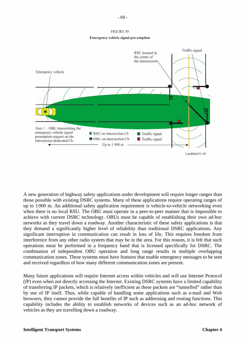
- 69 -
Intelligent Transport Systems Chapter 4
A new generation of highway safety applications under development will require longer ranges than those possible with existing DSRC systems. Many of these applications require operating ranges of up to 1 000 m. An additional safety application requirement is vehicle-to-vehicle networking even when there is no local RSU. The OBU must operate in a peer-to-peer manner that is impossible to achieve with current DSRC technology. OBUs must be capable of establishing their own ad-hoc networks as they travel down a roadway. Another characteristic of these safety applications is that they demand a significantly higher level of reliability than traditional DSRC applications. Any significant interruption in communication can result in loss of life. This requires freedom from interference from any other radio system that may be in the area. For this reason, it is felt that such operations must be performed in a frequency band that is licensed specifically for DSRC. The combination of independent OBU operation and long range results in multiple overlapping communication zones. These systems must have features that enable emergency messages to be sent and received regardless of how many different communication zones are present.
Many future applications will require Internet access within vehicles and will use Internet Protocol (IP) even when not directly accessing the Internet. Existing DSRC systems have a limited capability of transferring IP packets, which is relatively inefficient as these packets are “tunnelled” rather than by use of IP itself. Thus, while capable of handling some applications such as e-mail and Web browsers, they cannot provide the full benefits of IP such as addressing and routing functions. This capability includes the ability to establish networks of devices such as an ad-hoc network of vehicles as they are travelling down a roadway.

- 70 -
Chapter 4 Intelligent Transport Systems
Another future need is to provide an integrated communication system in vehicles, recognizing that there is no single communication means that satisfies all future requirements. There is a role for multiple systems, such as mobile phones, satellite, and DSRC. No single media will satisfy all future applications. What is desired is to allow each on-board device or application needing to communicate outside of the vehicle communications media to have access to any or all of the various communication capabilities that may exist in that vehicle, using the one that best fits the immediate needs and capabilities. This leads to the need for a layer within the architecture that permits and manages the routing of data to/from any application within the vehicle to any communications device that is available.
4.5.4.5 Internet concept and Protocol
The general concept desired is that any on-board device or application be able to treat DSRC as just another node on the Internet. The goal then, is to allow this on-board application to send messages at any time to any other node on the Internet. An example would be for a business application on the vehicle to send data to a specific address within the home business network. Conversely, that home office may need to send a message to a client application in a specific vehicle that may be located anywhere.
This concept is illustrated in Fig. 51, where the home domain may be fixed, but the vehicle moves about a region, accessing the Internet at a variety of points. This introduces the problem of the home domain knowing how to address a particular vehicle when it may suddenly appear at any access point in any domain. The corollary to this is an application on the vehicle wishing to address a message to the home office. The addressing/routing information required will be changing with every RSU encountered.
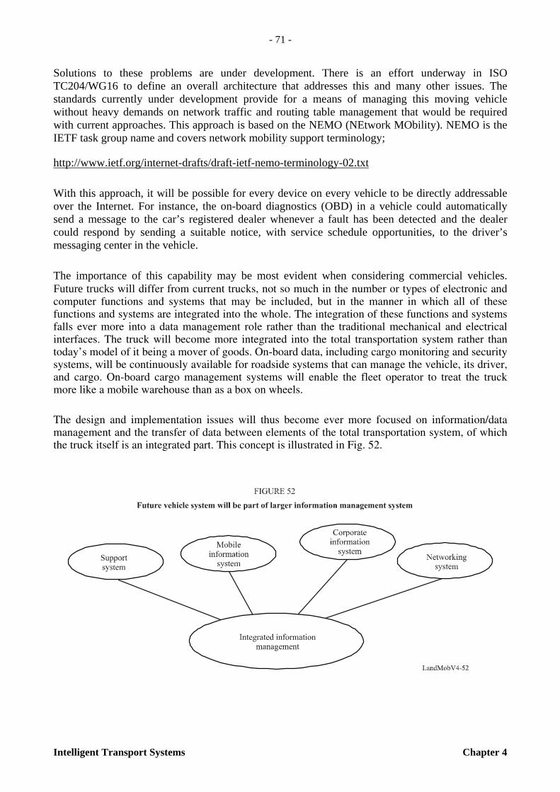
- 71 -
Intelligent Transport Systems Chapter 4
Solutions to these problems are under development. There is an effort underway in ISO TC204/WG16 to define an overall architecture that addresses this and many other issues. The standards currently under development provide for a means of managing this moving vehicle without heavy demands on network traffic and routing table management that would be required with current approaches. This approach is based on the NEMO (NEtwork MObility). NEMO is the IETF task group name and covers network mobility support terminology;
http://www.ietf.org/internet-drafts/draft-ietf-nemo-terminology-02.txt
With this approach, it will be possible for every device on every vehicle to be directly addressable over the Internet. For instance, the on-board diagnostics (OBD) in a vehicle could automatically send a message to the car’s registered dealer whenever a fault has been detected and the dealer could respond by sending a suitable notice, with service schedule opportunities, to the driver’s messaging center in the vehicle.
The importance of this capability may be most evident when considering commercial vehicles. Future trucks will differ from current trucks, not so much in the number or types of electronic and computer functions and systems that may be included, but in the manner in which all of these functions and systems are integrated into the whole. The integration of these functions and systems falls ever more into a data management role rather than the traditional mechanical and electrical interfaces. The truck will become more integrated into the total transportation system rather than today’s model of it being a mover of goods. On-board data, including cargo monitoring and security systems, will be continuously available for roadside systems that can manage the vehicle, its driver, and cargo. On-board cargo management systems will enable the fleet operator to treat the truck more like a mobile warehouse than as a box on wheels.
The design and implementation issues will thus become ever more focused on information/data management and the transfer of data between elements of the total transportation system, of which the truck itself is an integrated part. This concept is illustrated in Fig. 52.
- 72 -
Chapter 4 Intelligent Transport Systems
aageae To AirlinkScope of IEEE P1609.3 standardScope of IEEE 802.1 standard
This will put new demands on both on-board and off-board communications systems. On-board communications will probably include a data network dedicated to computers such as laptops, navigation systems, cargo monitoring, advanced displays, and central vehicle controllers. This could be based on the Internet Protocol (IP) and may be wired or wireless. For off-board communications, cell phone and satellite communications are already commonplace and can be expected to remain valuable means of communicating off-vehicle. However, the new IP based DSRC will be entering service within the next few years, and is expected to alter the mix of off-board communications in use. The technology will allow high-speed internet access whenever a vehicle is within range of a roadside antenna.
The resulting external communications will result in multiple options for on-board systems to communicate with roadside systems. The ISO TC 204/WG16 effort has defined a new architecture that allows any device on the vehicle to send and receive messages across any of these communication systems via a single access point. This would allow a device to use whichever communication service best meets the immediate needs rather than being dedicated to a particular service or having to support multiple interfaces, one for each service. With the combination of these architectures and IP-based DSRC communications, not only could each vehicle have its own internet address, but each device within that vehicle could have its own assigned address. The vision of such efforts is that the present land-based internet would be seamlessly brought into, and become a part of, the vehicle and all of the systems on the vehicle. A trucking fleet could then have direct access to the on-board systems of any of the trucks in their fleet regardless of where that truck is at the moment. This information could include vehicle information, cargo information, and operator interfaces.
4.5.4.6 Internet Protocol based DSRC
The ITS programs in North America have identified a large number of potential ways in which the highways can be made safer and to also operate more efficiently (reducing congestion). A large number of these applications require DSRC for communication from the vehicle to the road-side and also for communication from one vehicle to another. In evaluating these applications, it was immediately obvious that existing DSRC systems could not satisfy the requirements, especially for operating range, peer to peer interactions, and vehicle to vehicle communications. The result was the initiation of a new project to develop a new class of DSRC technology.
The initial task in this project was to evaluate over a hundred proposed applications to determine the requirements for this future communication system. The most demanding were those applications affecting highway safety. The types of requirements derived from this analysis include:
– Full interoperability throughout all of North America
– Full two-way communications – vehicle to roadside – vehicle to vehicle
– Low latency (few ms to establish connection)
– Security and anonymity
– Widely deployable (many overlapping zones)

- 73 -
Intelligent Transport Systems Chapter 4
– Long range (up to 1 000 m)
– High data rates (up to 54 Mbit/s)
– Support for the full range of applications and installations
– Meet business needs (cost, schedule, etc.).
To ensure that safety related applications could be serviced with extremely high quality of service, it was determined that it would be necessary to have a licensed radio spectrum for which DSRC was the primary user. The existing radio bands for DSRC are unlicensed and subject to interference from other unlicensed users. Also, many of these safety applications required operating ranges (power levels) that could not be supported in existing unlicensed bands. For this reason, part of the program was to have a common band allocated throughout North America which would be licensed, with DSRC as the primary user. The 5 855 to 5 925 MHz band has been approved and will be used within all of North America (some channel differences exist between United States of America and Canada, but are relatively minor and accounted for in the standards).
The primary goal is the ability to have DSRC radios installed as a permanent, built-in, part of all new cars sold in North America with full interoperability for all safety related applications. This goal requires widespread market acceptance (implying low cast and low technological risk among other things), and rapid deployment capabilities. The core technology selected was IEEE 802.11 (Wi-Fi) and specifically, IEEE 802.11a, which offered multiple advantages over the more commonly implemented IEEE 802.11b. IEEE 802.11 cannot be used directly in the highway environment, and some modifications are required to support such differences as the multi-path and Doppler problems that exist. Also, many of the applications require very short response times, on the order of milliseconds. The necessary modifications to the basic IEEE 802.11 standard are being added with IEEE 802.11p. In addition, IEEE P1609 has been developed for the upper layers and security. The result is a DSRC system based on the architecture shown in Fig. 53.

- 74 -
Chapter 4 Intelligent Transport Systems
To support the need for multiple overlapping communications zones, in North America, the frequency band has been divided into 7 channels of 10 MHz each as shown in Fig. 54. Channel 178 is used as a control channel, on which broadcast announcements of services are being offered at that location and high priority short messages. If a bi-directional exchange of data is to be started, or the messages are low priority, then the announcement identifies that the receiving device switch to the Service Channel that has been granted to this location. Data exchanges are conducted within these Service Channels. Using the features defined in IEEE 803.11p and IEEE P1609.3, many different devices may have overlapping communication zones, but all are able to transmit their announcements and priority short messages.
This approach, basing future DSRC on IP technology, has been thoroughly tested and simulated with the results indicating that it can satisfy all of the technical requirements with existing chip sets. All of the major automobile manufacturers have agreed to the use the new standards and are planning to include the DSRC radios and many of the safety applications as standard equipment in future cars. The various auto manufacturers are working with the US Department of Transportation to conduct tests which should verify a relatively extensive initial deployment both in a large number of vehicles and a regional infrastructure to verify the various elements of a complete national system. These tests will include vehicle-to-vehicle and vehicle-to-roadside communications plus the local, regional, and national elements of the roadside infrastructure.

- 75 -
Intelligent Transport Systems Chapter 5
CHAPTER 5
MILLIMETRE WAVE COMMUNICATIONS
5.1 Introduction
The millimetre-wave region of the electromagnetic spectrum corresponds to radio band frequencies of 30 GHz to 300 GHz (wavelength from 10 mm to 1 mm). One of the most important features of millimetre waves is in transmitting large amounts of data required for transmission of, e.g., large computer data, multiplexed television or voice channels for relay transmitters for broadcasting. In addition, millimetre waves’ high frequency realizes small equipment size including the compact high gain antenna suited for vehicular use.
Millimetre waves are used in ITS as an important communication and detection media. Particularly in radar system, the millimetre wave can easily create a narrow beam that is desirable to discriminate small distant objects. Major millimetre wave radio spectrum allocations for ITS in USA, Europe and Japan are shown below:
USA:
– 76-77 GHz: Vehicle radar collision avoidance systems
– 22-29 GHz: Vehicular radar system (UWB: ultra wide band)
Europe:
– 63-64 GHz: Vehicle-to-vehicle and road-to-vehicle communications.
– 76-77 GHz: Vehicular radar, anti-collision, and cruise control systems.
– 21.65-26.65 GHz: Automotive short-range radar equipment.
– 77-81 GHz: Automotive short-range radar equipment.
Japan:
– 76-77 GHz: Vehicular radar system
– 60-61 GHz: Vehicular radar system
The frequency band around 60 GHz is best suited for secure short-range communications, such as vehicle to vehicle communication and short range radar, because at 60 GHz, oxygen molecules in the air interact with electromagnetic radiation and absorb the transmitted energy preventing the long reach of transmitted waves. It reduces interferences among vehicle communications and significantly contributes to efficient use of radio frequency resources. Figure 55 shows the specific attenuation due to atmospheric gases. Transmission losses occur when millimetre waves travelling through the atmosphere are absorbed by molecules of oxygen, water vapour and other gaseous atmospheric constituents. These losses are greater at certain frequencies, coinciding with the mechanical resonant frequencies of the gas molecules. Around 60 GHz, absorption by molecules of oxygen shows a peak.
- 76 -
Chapter 5 Intelligent Transport Systems
Electromagnetic wave propagation at 60 GHz band experiences much higher path loss due to rain and oxygen molecules absorption in addition to diffraction, scattering due to vegetation etc. The specific characteristic of 60 GHz band made this band widely used for short range small power communications for unlicensed use.
The U.S. Federal Communications Commission (FCC) allocated a continuous 7 GHz band of a spectrum between 57 and 64 GHz for wireless communications for unlicensed use in 2001. In Europe, CEPT-ERC (European Conference of Postal and Telecommunications Administrations – European Radio communications Committee) made an allocation to RTTT (ITS) systems via an ERC Decision (ERC/DEC(92)02) in 1992, the 63 to 64 GHz band allocated for vehicle-to-vehicle and road-to-vehicle communication systems. In 2002, the Electronic Communications Committee (ECC) withdrew ERC Decision (92)02 and replaced it by ECC Decision (02)01, entering in force on 15 March 2002.
- 77 -
Intelligent Transport Systems Chapter 5
In Japan, the Ministry of Posts and Telecommunications (now MIC) revised the licensing rule on the 60 GHz band for the small power radio stations to realize the unlicensed use in the spectrum band of 59 GHz to 66 GHz in 2000. These small power radio stations may be used for the transceivers for inter-vehicle communications and road to vehicle communications. These stations also include the vehicular radar that had been already assigned in this band.
Advantages of millimetre waves to ITS radiocommunication including radar systems are summarized as follows:
– Broad bandwidths for high data rate information transfer
– Low probability of interference due to high attenuation in the air
– Small multipath fading
– Low transmission power due to high antenna gain
– Small antenna and equipment size due to higher frequency
– High directivity and spatial resolution.
5.2 Vehicular radar
5.2.1 Background
Sensor technologies for monitoring and identifying objects near vehicles are the most important safety-related base technologies for developing systems that will accommodate this purpose. Various types of sensors have been studied and developed, and through this research and development, it has become clear that a RADAR (radio detection and ranging) using radio waves is suitable for this objective. An international effort to regulate short-range radar for vehicular applications is crucial for ensuring stable radar operations and effective use of frequency resources. In accordance with the Radio Regulation, the 60-61 GHz and 76-77 GHz bands were considered suitable for radar system due to the radio wave absorption characteristics in the atmosphere as described above. The 76 GHz band has already been assigned by the Federal Communications Commission (FCC) for vehicular radars in the United States of America. The Ministry of Internal Affairs and Communications (MIC) in Japan has assigned the 60-61 GHz and 76-77 GHz bands for low power, short-range vehicular radars. Furthermore, in accordance with European spectrum requirements for RTTT established in 2002, ETSI has adopted a European standard for low power vehicle radar operating in the 76-77 GHz band (EN 301 091) in 1998. In 2000, Recommen-dation ITU-R M.1452 for low power, short-range vehicular radar operating in the 60-61 GHz, and 76-77 GHz bands was approved and published.
In Europe, ultra wide band (UWB) short range radar (SRR) operating at 24 GHz is considered to be a key technology for the rapid and cost-effective introduction of many intelligent vehicle safety systems. In January 2005, the European Commission decided on the time-limited (until 1 July 2013) use of the 24 GHz range radio spectrum band for the ultra-wide band part of short-range vehicle radar equipment. After this deadline SRR equipment is intended to operate in the frequency band 77 to 81 GHz on a permanent base, see ECC/DEC/(04)03. Applications operating around the 24 GHz band would increasingly suffer significant levels of harmful interference if a certain level of

- 78 -
Chapter 5 Intelligent Transport Systems
penetration of vehicles using the 24 GHz range radio spectrum band for short-range radars was to be exceeded. According to CEPT (European Conference of Postal and Telecommunications Administrations), the sharing between earth exploration satellite services and short-range vehicle radar could only be feasible on a temporary basis.
5.2.2 Low power vehicular radar at 60 GHz and 76 GHz
5.2.2.1 General
Low power short-range vehicular radar can detect the conditions within about 100 m from a vehicle using millimetre waves. This system is expected to avoid collisions and other accidents. The low power short-range vehicular radar will be used for adaptive cruise control (ACC.) and “autonomous driving” in the future. The main advantage of radar over competing devices, such as a laser or infrared vision equipment, is its resistance to bad weather (rain, fog and snow) and dirt. Short-range radar is suitable for vehicles driven in severe conditions.
Figure 56 shows an example of low power short-range radar for vehicles.
Figure 57 shows the configuration of short-range radar for vehicles.
- 79 -
Intelligent Transport Systems Chapter 5
Antenna and RF unit: This part consists of a transmitting antenna, a receiving antenna, receiving equipment and transmission equipment. Signal modulations, conversions to high frequencies, radio-wave transmission, and radio-wave reception are handled in this part. This part could be equipped with several antennas and could perform beam scanning.
Signal processing unit: This unit renders distance and speed by calculating signals handed over from the RF unit. Rendering of average distance and speed, and eradication of interference are sometimes handled here. When the antenna performs beam scanning, this unit calculates the direction of objects found.
Recognition unit: This unit can select and arrange the most wanted or necessary data depending on the needs of each system. For example, the unit will recognize the most dangerous obstacles, and can judge whether the vehicle in front is in lane. The unit occasionally averages figures gathered, filters interference, and enhances measuring accuracy and reliability of data from other sensors.
5.2.2.2 System requirements Following are system requirements extracted from the Recommendation ITU-R M.1452 – Low power short-range vehicular radar equipment at 60 GHz and 76 GHz.
a) Radio-frequency band – 60 GHz band: 60-61 GHz. – 76 GHz band: 76-77 GHz.
b) Radar method and modulation method 2
The following four radar methods (with modulation methods) are recommended: – FM-CW method (frequency modulation) – Pulse method (pulse modulation) – Two frequencies CW method (no modulation or frequency modulation) – Spread spectrum method (direct sequence spread spectrum).
c) Transmitting power and antenna gain Transmitting power (power transferred to antenna) 10 mW or less (peak power). Antenna gain: 40 dB or less.
d) Specified bandwidth Up to 1.0 GHz.
____________________ 2 Two frequencies CW method detects the distance to the vehicle through phase difference between two carriers, and
detects relative velocity to the vehicle by the Doppler effect that shifts the frequency of the radar beam due to movement of the vehicle. Details of other modulation methods are described in Annex 4 “Examples of modulation schemes” of ETSI EN 301 091-1 V1.2.1, Road Transport and Traffic Telematics (RTTT); Radar equipment operating in the 76 GHz to 77 GHz range; Part 1: Technical characteristics and test methods for radar equipment operating in the 76 GHz to 77 GHz range.
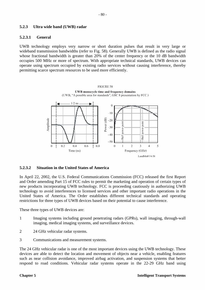
- 80 -
Chapter 5 Intelligent Transport Systems
5.2.3 Ultra wide band (UWB) radar
5.2.3.1 General
UWB technology employs very narrow or short duration pulses that result in very large or wideband transmission bandwidths (refer to Fig. 58). Generally UWB is defined as the radio signal whose fractional bandwidth is greater than 20% of the center frequency or the 10 dB bandwidth occupies 500 MHz or more of spectrum. With appropriate technical standards, UWB devices can operate using spectrum occupied by existing radio services without causing interference, thereby permitting scarce spectrum resources to be used more efficiently.
5.2.3.2 Situation in the United States of America
In April 22, 2002, the U.S. Federal Communications Commission (FCC) released the first Report and Order amending Part 15 of FCC rules to permit the marketing and operation of certain types of new products incorporating UWB technology. FCC is proceeding cautiously in authorizing UWB technology to avoid interferences to licensed services and other important radio operations in the United States of America. The Order establishes different technical standards and operating restrictions for three types of UWB devices based on their potential to cause interference.
These three types of UWB devices are:
1 Imaging systems including ground penetrating radars (GPRs), wall imaging, through-wall imaging, medical imaging systems, and surveillance devices.
2 24 GHz vehicular radar systems.
3 Communications and measurement systems.
The 24 GHz vehicular radar is one of the most important devices using the UWB technology. These devices are able to detect the location and movement of objects near a vehicle, enabling features such as near collision avoidance, improved airbag activation, and suspension systems that better respond to road conditions. Vehicular radar systems operate in the 22-29 GHz band using
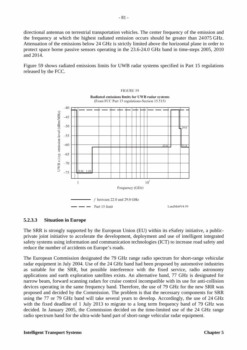
- 81 -
Intelligent Transport Systems Chapter 5
directional antennas on terrestrial transportation vehicles. The center frequency of the emission and the frequency at which the highest radiated emission occurs should be greater than 24 075 GHz. Attenuation of the emissions below 24 GHz is strictly limited above the horizontal plane in order to protect space borne passive sensors operating in the 23.6-24.0 GHz band in time-steps 2005, 2010 and 2014.
Figure 59 shows radiated emissions limits for UWB radar systems specified in Part 15 regulations released by the FCC.
5.2.3.3 Situation in Europe
The SRR is strongly supported by the European Union (EU) within its eSafety initiative, a public-private joint initiative to accelerate the development, deployment and use of intelligent integrated safety systems using information and communication technologies (ICT) to increase road safety and reduce the number of accidents on Europe’s roads.
The European Commission designated the 79 GHz range radio spectrum for short-range vehicular radar equipment in July 2004. Use of the 24 GHz band had been proposed by automotive industries as suitable for the SRR, but possible interference with the fixed service, radio astronomy applications and earth exploration satellites exists. An alternative band, 77 GHz is designated for narrow beam, forward scanning radars for cruise control incompatible with its use for anti-collision devices operating in the same frequency band. Therefore, the use of 79 GHz for the new SRR was proposed and decided by the Commission. The problem is that the necessary components for SRR using the 77 or 79 GHz band will take several years to develop. Accordingly, the use of 24 GHz with the fixed deadline of 1 July 2013 to migrate to a long term frequency band of 79 GHz was decided. In January 2005, the Commission decided on the time-limited use of the 24 GHz range radio spectrum band for the ultra-wide band part of short-range vehicular radar equipment.

- 82 -
Chapter 5 Intelligent Transport Systems
The industrial consortium SARA (short-range automotive radar frequency allocation) founded in March 2001, consisting of members from car manufacturers and suppliers, has been working in EU to come up with a regulatory solution for 24 GHz UWB vehicular radars. Table 12 shows the characteristics of ACC (automatic cruise control) and UWB vehicular radar. Figure 60 provides the different applications of vehicular radar.
TABLE 12
ACC and UWB radars
Source: ITU-T workshop on standardization in telecommunication for motor vehicles, held 24 to 25 November 2003 (http://www.itu.int/ITU-T/worksem/telecomauto/index.html)
5.3 Future trends
5.3.1 Background
It is important to utilize millimetre wave for vehicle-to-vehicle communications, as well as for communication between the vehicle and a roadside infrastructure because of such advantageous characteristics as line of sight communication and high propagation loss. Millimetre waves have the potential to provide broadband and secure radiocommunication for transportation and vehicle safety applications. The necessity to undertake an effort to develop a new Recommendation on vehicle-to-vehicle communications is identified in Recommendation ITU-R M.1310 – Transport information and control systems (TICS) – Objectives and requirements.
Items ACC (77 GHz radar)
UWB short-range radar (24 GHz)
Range 2-120 m 0.3-30 m Resolution 100 cm (bandwidth 0.5 GHz) 3 cm (bandwidth 5 GHz) Features Multi target capability,
weather robustness Reliable, complete coverage of vehicles front area
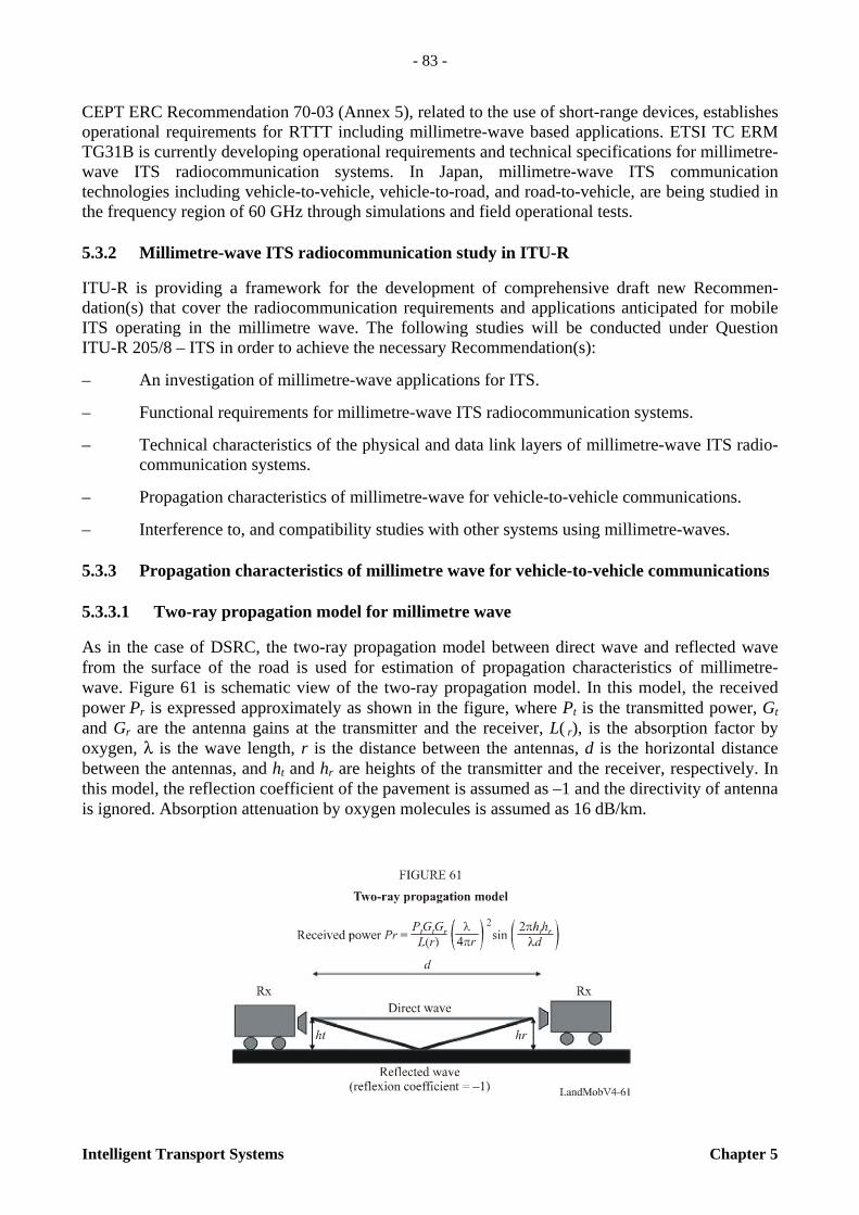
- 83 -
Intelligent Transport Systems Chapter 5
CEPT ERC Recommendation 70-03 (Annex 5), related to the use of short-range devices, establishes operational requirements for RTTT including millimetre-wave based applications. ETSI TC ERM TG31B is currently developing operational requirements and technical specifications for millimetre-wave ITS radiocommunication systems. In Japan, millimetre-wave ITS communication technologies including vehicle-to-vehicle, vehicle-to-road, and road-to-vehicle, are being studied in the frequency region of 60 GHz through simulations and field operational tests.
5.3.2 Millimetre-wave ITS radiocommunication study in ITU-R
ITU-R is providing a framework for the development of comprehensive draft new Recommen-dation(s) that cover the radiocommunication requirements and applications anticipated for mobile ITS operating in the millimetre wave. The following studies will be conducted under Question ITU-R 205/8 – ITS in order to achieve the necessary Recommendation(s):
– An investigation of millimetre-wave applications for ITS.
– Functional requirements for millimetre-wave ITS radiocommunication systems.
– Technical characteristics of the physical and data link layers of millimetre-wave ITS radio-communication systems.
– Propagation characteristics of millimetre-wave for vehicle-to-vehicle communications.
– Interference to, and compatibility studies with other systems using millimetre-waves.
5.3.3 Propagation characteristics of millimetre wave for vehicle-to-vehicle communications
5.3.3.1 Two-ray propagation model for millimetre wave
As in the case of DSRC, the two-ray propagation model between direct wave and reflected wave from the surface of the road is used for estimation of propagation characteristics of millimetre-wave. Figure 61 is schematic view of the two-ray propagation model. In this model, the received power Pr is expressed approximately as shown in the figure, where Pt is the transmitted power, Gt and Gr are the antenna gains at the transmitter and the receiver, L( r), is the absorption factor by oxygen, λ is the wave length, r is the distance between the antennas, d is the horizontal distance between the antennas, and ht and hr are heights of the transmitter and the receiver, respectively. In this model, the reflection coefficient of the pavement is assumed as –1 and the directivity of antenna is ignored. Absorption attenuation by oxygen molecules is assumed as 16 dB/km.

- 84 -
Chapter 5 Intelligent Transport Systems
5.3.3.2 Results of field operational tests
5.3.3.2.1 Experimental facility for vehicle-to-vehicle communications
Figure 62 shows the configuration of the experimental measurement system. The frequency for the propagation characteristic measurement is 59.1 GHz.
On the transmitting side, the signal generator makes the IF carrier frequency of 140 MHz. Then the IF signal is up-converted to RF signal at 59.1 GHz. On the receiving side, two RF units are mounted on the front of the vehicle. After the received RF signals are down-converted to IF frequency, received power is measured.
The test course was a straight two-lane strip of pavement, almost 200 m in length. The precedent car was parked at the end of the road, and the following car approached to the precedent car at the constant speed of 2.5 m/s.
Table 13 shows the specifications for the experimental measurement system. The transmitted power is – 4 dBm. Each antenna at Tx and Rx is a standard horn antenna with the gain of 24 dBi, and these are installed at heights of 46 cm (Tx.A), 85 cm (Rx.B), and 38 cm (Rx.C) respectively.
TABLE 13
Specifications of experimental measurement system
Centre frequency 59.1 GHz
Transmitted power – dBm
Antenna gain 24 dBi
Polarization Vertical

- 85 -
Intelligent Transport Systems Chapter 5
5.3.3.2.2 Results of field operational tests compared with the estimated value
Figure 63 shows the measurement results of the received power. The horizontal axis represents the distance between the vehicles. The estimated received power using the two-ray propagation model is also described in Fig. 63. The results of measured power are similar to those obtained by the two-ray propagation model. Figure 64 shows the measurement results in the case that the height space-diversity is employed. The received power is not degraded as much as in the case where height space-diversity is not employed. This result shows that the height space-diversity is effective for the millimetre-wave vehicle-to-vehicle system.

- 86 -
Chapter 5 Intelligent Transport Systems
Figure 65 shows the measured results and the calculated results of the received power in the case of high-speed driving on the expressway. The characteristics of received power are different from those of the two-ray model. This may be caused by the fluctuation of the vehicles’ motion.

- 87 -
Intelligent Transport Systems Chapter 5
5.3.4 Inter-vehicle communications and radar
For safety and driver comfort, simultaneous use of communication and radar is very effective. A vehicle can be loaded with the transceiver and the radar separately or it can be loaded with the radar with communication function. To enhance the function of the ACC (adaptive cruise control) radar, the implementation of a communication function into the radar is very effective.
5.3.4.1 Communication through radar
As for ITS radiocommunication systems, both large-capacity transmission systems such as those for multi-media transmission, and small-capacity transmission systems such as those that support safe vehicle operation are considered. The collision avoidance radar supports safe vehicle operation. If a communication function is added to the radar, more benefits can be expected. For example, drivers can obtain operational information from the vehicles ahead of them or safety information from signposts along the road. Figure 66 shows the concept of a safety enhancement system which consists of onboard radars with communications function and transponders on vehicles or signposts.
This integrated system of radar with communications function and transponder works in the following situations, for example:
– When no communications partner exists, that is, the transponder does not exist around the radar; this system can be used only as the collision avoidance radar.
– When a communications partner exists, the radar can communicate with transponder and can receive information from the partner.
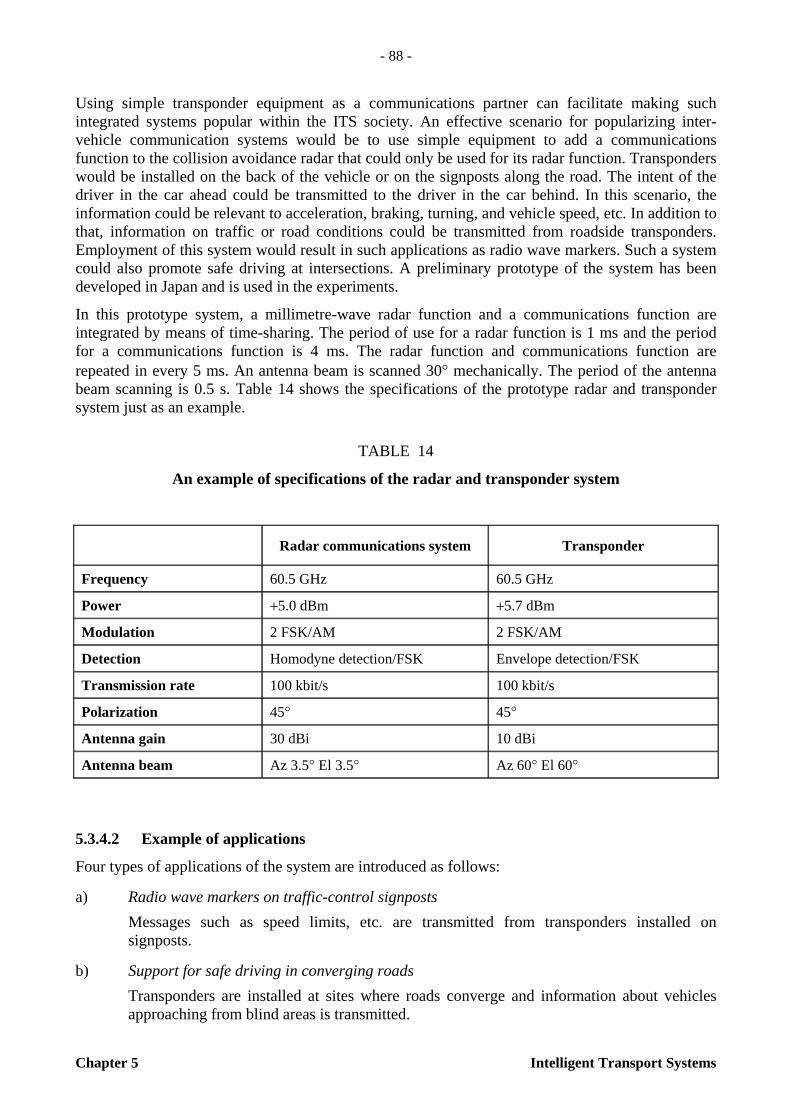
- 88 -
Chapter 5 Intelligent Transport Systems
Using simple transponder equipment as a communications partner can facilitate making such integrated systems popular within the ITS society. An effective scenario for popularizing inter-vehicle communication systems would be to use simple equipment to add a communications function to the collision avoidance radar that could only be used for its radar function. Transponders would be installed on the back of the vehicle or on the signposts along the road. The intent of the driver in the car ahead could be transmitted to the driver in the car behind. In this scenario, the information could be relevant to acceleration, braking, turning, and vehicle speed, etc. In addition to that, information on traffic or road conditions could be transmitted from roadside transponders. Employment of this system would result in such applications as radio wave markers. Such a system could also promote safe driving at intersections. A preliminary prototype of the system has been developed in Japan and is used in the experiments.
In this prototype system, a millimetre-wave radar function and a communications function are integrated by means of time-sharing. The period of use for a radar function is 1 ms and the period for a communications function is 4 ms. The radar function and communications function are repeated in every 5 ms. An antenna beam is scanned 30° mechanically. The period of the antenna beam scanning is 0.5 s. Table 14 shows the specifications of the prototype radar and transponder system just as an example.
TABLE 14
An example of specifications of the radar and transponder system
5.3.4.2 Example of applications
Four types of applications of the system are introduced as follows:
a) Radio wave markers on traffic-control signposts Messages such as speed limits, etc. are transmitted from transponders installed on
signposts.
b) Support for safe driving in converging roads Transponders are installed at sites where roads converge and information about vehicles
approaching from blind areas is transmitted.
Radar communications system Transponder
Frequency 60.5 GHz 60.5 GHz
Power +5.0 dBm +5.7 dBm
Modulation 2 FSK/AM 2 FSK/AM
Detection Homodyne detection/FSK Envelope detection/FSK
Transmission rate 100 kbit/s 100 kbit/s
Polarization 45° 45°
Antenna gain 30 dBi 10 dBi
Antenna beam Az 3.5° El 3.5° Az 60° El 60°

- 89 -
Intelligent Transport Systems Chapter 5
c) Intersection safety
At intersections with blind spots, information is transmitted from a transponder with functions that receive the message from a hidden, approaching vehicle and repeat the message.
d) Rear-end collision avoidance alarm
An alarm message is transmitted to the approaching vehicle from the transponder on the rear of the vehicle ahead. A vehicle ahead sends the alarm message to a following vehicle. Adding a simple communications function to existing collision avoidance radar, this radar communications system can take a simple architecture and have an effective support function for safe driving. Such a radar communications system will be used as the next generation of intelligent transport systems.

- 91 -
Intelligent Transport Systems Annex 1
ANNEX 1
RESOURCES
As the status of ITS technology, field deployment and business is changing rapidly, the contents of this Handbook would be old-fashioned in near future. So in this section, it shows the list of ITS related web site worldwide.
1 The Americas
– http://www.itsa.org/: ITS America – http://www.itscanada.ca: ITS Canada – http://www.stiargentina.org.ar: ITS Argentina – http://www.itsb.org.br: ITS Brazil – http://www.itschile.cl: ITS Chile – http://www.itsperu.org: ITS Peru – www.itspan.org/: PAITX
2 Europe
– http://www.nen.nl/cen278: CEN Technical Committee 278 – http://www.ertico.com/: ERTICO – ITS Europe – http://portal.etsi.org/Portal_Common/home.asp: ETSI/ERM Technical Group 37’ – http://www.iso-calm.de/Public/CALMintro.html: CALM-Website – http://www.eScope.info: eSafety initiative – http://europa.eu.int/comm/research/transport/tran_trends/systems_en.html: EU-Site – http://www.sanewsletters.com/its/calendar.asp: ITS Events calendar – http://www.ictsb.org/itssg_home.htm: Intelligent Transport Systems Steering Group
3 Japan
– http://www.soumu.go.jp/joho_tsusin/eng/index.html: Ministry of Internal Affairs and Com-munications
– http://www.npa.go.jp/koutsuu/kisei/its/index.htm: National Police Agency
– http://www.meti.go.jp/english/index.html: Ministry of Economy, Trade and Industries
– http://www.mlit.go.jp/jidosha/anzen/chuu/index00.html: Road Transport Bureau, Ministry of Land Infrastructure and Transport
– http://www.mlit.go.jp/road/ITS/j-html/index.html: Road Bureau, Ministry of Land Infras-tructure and Transport

- 92 -
Annex 1 Intelligent Transport Systems
– http://www.itsforum.gr.jp/E_index.html: ITS Info-Communications Forum, Japan – http://www.internetits.org/en/top.html: Internet ITS Consortium – http://www.nilim.go.jp/japanese/its/index.htm: National Institute for Land and Infras-
tructure Management – http://www.jsae.or.jp/index_e.php: The Society of Automotive Engineers of Japan – http://www2.nict.go.jp/is/t822/108/index-e.html: Yokosuka ITS Research Center, National
Institute of Information and Communications Technology – http://www.utms.or.jp/english/index.html: Universal Traffic Management Society of Japan – http://www.ahsra.or.jp/index_e.html: Advanced Cruise-Assist Highway System Research
Association – http://www.jeita.or.jp/english/: Japan Electronics and Information Technology Industries
Association – http://www.arib.or.jp/english/index.html: Association of Radio Industries and Businesses – http://www.vics.or.jp/english/index.html: Vehicle Information and Communication System
Center – http://www.orse.or.jp/english/: Organization of Road System Enhancement – http://www.hido.or.jp/ITSHP_e/: Highway Industry Development Organization – http://www.jari.or.jp/en/: Japan Automobile Research Institute – http://www.jama.org/: Japan Automobile Manufacturers Association
4 Korea
– http://www.moct.go.kr/: Ministry of Construction and Transport – http://www.mic.go.kr/: Ministry of Information and Communication – http://www.freeway.co.kr/: Korea Highway Corporation – http://www.ktnews.net/: Korea Transport News – http://www.koti.re.kr/: Korea Transport Institute – http://www.itskorea.or.kr/: ITS Korea – http://www.tta.or.kr/: Telecommunication Technology Association – http://www.spatic.go.kr/www/: Seoul Police Traffic Center – http://www.seoul.npa.go.kr/: Seoul Metropolitan Expressway Traffic Center – http://www.rotis.com/: ROTIS – http://www.ktf.com/: KTF – http://www.sktelecom.com/: SKTelecom – http://www.lgtelecom.com/: LGTelecom
- 93 -
Intelligent Transport Systems Annex 2
ANNEX 2
VICS
In this annex, technical and operational information on VICS (vehicle information and communication system) service is described.
1 Introduction
In Japan, an advanced traveller information system called “VICS” (vehicle information and communication system) service has been in operation since April 1996. VICS units installed in vehicle navigation equipment have spread rapidly, and cumulative shipment had exceeded 11.88 million units at the end of March 2005. The reason for such rapid popularization of VICS is the increasing need for real-time road traffic information supported by the enlargement of areas covered by the service. Other factors include the rapid increase of navigation equipment incorporating VICS receivers that have resulted in unit price reductions.
2 Outline of the system
VICS (vehicle information and communication system) is a digital data communication system which promptly provides the latest necessary road traffic information to drivers via navigation equipment in the vehicle. Real-time information such as congestion and travel time of each area is transmitted to the drivers by using diagrams or characters. There are two types of information distribution media used in VICS. One is a broadcasting-based, wide area information distribution medium, FM multiplex broadcasting. The other is a beacon by which drivers can obtain information within a restricted area intermittently. The beacons are of two types: the radio wave beacon and the infrared beacon.
VICS provides three different types of information: – Map display;
– Simple graphic display; and
– Text display.
Drivers can use each of these to obtain a wide variety of road traffic information 24 hours a day, depending on the VICS-receiving device installed in their vehicles.
Figure 67 shows the outline of VICS. VICS has four functions: collection, editing/processing, distribution and utilization.
The VICS information includes “Traffic congestion”, “Travel time”, “Location of accidents and roadwork”, “Speed and lane regulations”, “Parking lot locations” and “Parking availability”. The VICS benefits are as follows:
– Avoid traffic congestion en-route
– Shorten travel time – Reduce driving-related stress
– No usage charge.
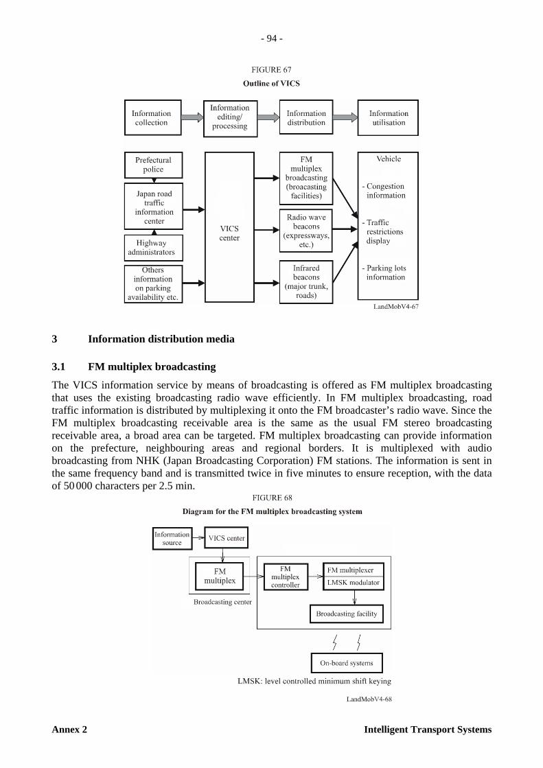
- 94 -
Annex 2 Intelligent Transport Systems
3 Information distribution media
3.1 FM multiplex broadcasting
The VICS information service by means of broadcasting is offered as FM multiplex broadcasting that uses the existing broadcasting radio wave efficiently. In FM multiplex broadcasting, road traffic information is distributed by multiplexing it onto the FM broadcaster’s radio wave. Since the FM multiplex broadcasting receivable area is the same as the usual FM stereo broadcasting receivable area, a broad area can be targeted. FM multiplex broadcasting can provide information on the prefecture, neighbouring areas and regional borders. It is multiplexed with audio broadcasting from NHK (Japan Broadcasting Corporation) FM stations. The information is sent in the same frequency band and is transmitted twice in five minutes to ensure reception, with the data of 50 000 characters per 2.5 min.
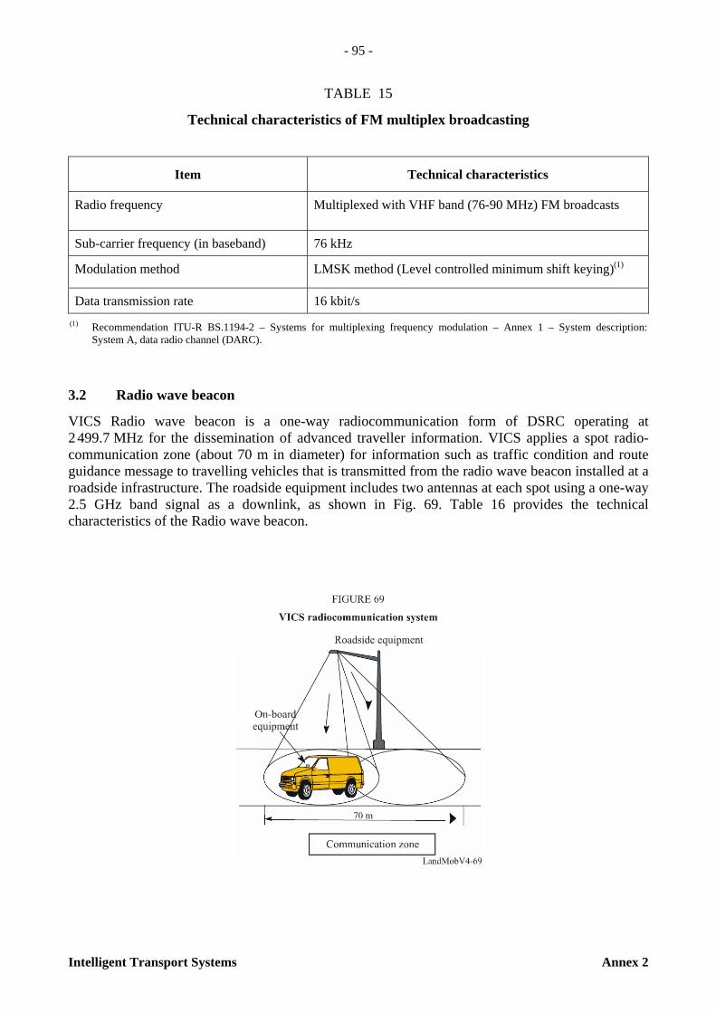
- 95 -
Intelligent Transport Systems Annex 2
TABLE 15
Technical characteristics of FM multiplex broadcasting
3.2 Radio wave beacon
VICS Radio wave beacon is a one-way radiocommunication form of DSRC operating at 2 499.7 MHz for the dissemination of advanced traveller information. VICS applies a spot radio-communication zone (about 70 m in diameter) for information such as traffic condition and route guidance message to travelling vehicles that is transmitted from the radio wave beacon installed at a roadside infrastructure. The roadside equipment includes two antennas at each spot using a one-way 2.5 GHz band signal as a downlink, as shown in Fig. 69. Table 16 provides the technical characteristics of the Radio wave beacon.
Item Technical characteristics
Radio frequency Multiplexed with VHF band (76-90 MHz) FM broadcasts
Sub-carrier frequency (in baseband) 76 kHz
Modulation method LMSK method (Level controlled minimum shift keying)(1)
Data transmission rate 16 kbit/s (1) Recommendation ITU-R BS.1194-2 – Systems for multiplexing frequency modulation – Annex 1 – System description:
System A, data radio channel (DARC).

- 96 -
Annex 2 Intelligent Transport Systems
TABLE 16
Technical characteristics of the Radio wave beacon
Item Technical characteristics
Radio frequency 2.5 GHz band (2 499.7 MHz)
Specified bandwidth Up to 85 kHz
Modulation method Double modulation of GMSK (Bb · T = 0.5) and amplitude modulation (modulation degree 10%)(1)
Data transmission rate 64 kbit/s
Transmitting power (Power fed to each antenna)
10 MW
Antenna gain 8.5 dB or less (1) Double modulation of GMSK (gaussian filtered minimum shift keying) and amplitude modulation is employed. By
two antennas that have different AM modulation over GMSK signal transmitting toward travelling direction and opposite travelling directions, beacon position is detected correctly within a few meters and travelling direction is also detected.
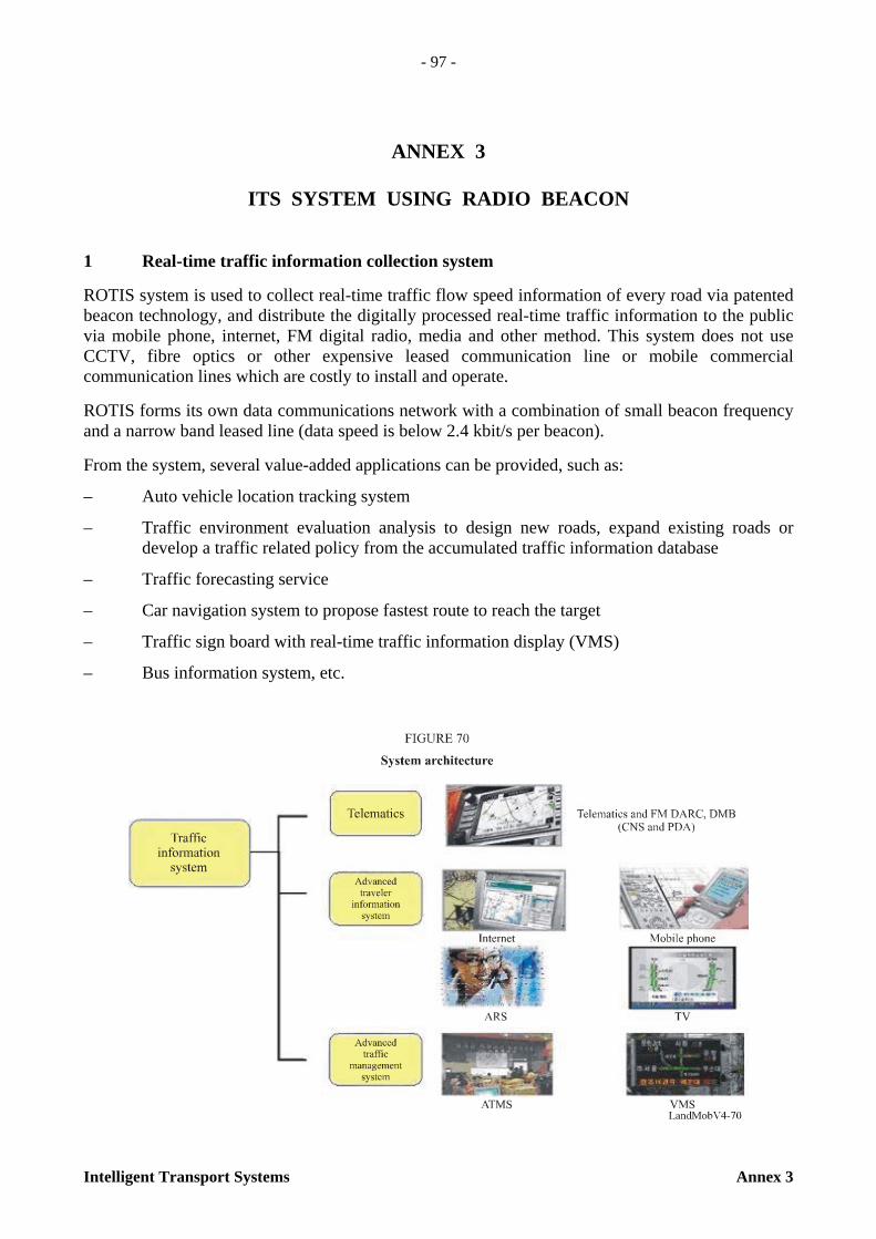
- 97 -
Intelligent Transport Systems Annex 3
ANNEX 3
ITS SYSTEM USING RADIO BEACON
1 Real-time traffic information collection system
ROTIS system is used to collect real-time traffic flow speed information of every road via patented beacon technology, and distribute the digitally processed real-time traffic information to the public via mobile phone, internet, FM digital radio, media and other method. This system does not use CCTV, fibre optics or other expensive leased communication line or mobile commercial communication lines which are costly to install and operate.
ROTIS forms its own data communications network with a combination of small beacon frequency and a narrow band leased line (data speed is below 2.4 kbit/s per beacon).
From the system, several value-added applications can be provided, such as:
– Auto vehicle location tracking system
– Traffic environment evaluation analysis to design new roads, expand existing roads or develop a traffic related policy from the accumulated traffic information database
– Traffic forecasting service
– Car navigation system to propose fastest route to reach the target
– Traffic sign board with real-time traffic information display (VMS)
– Bus information system, etc.
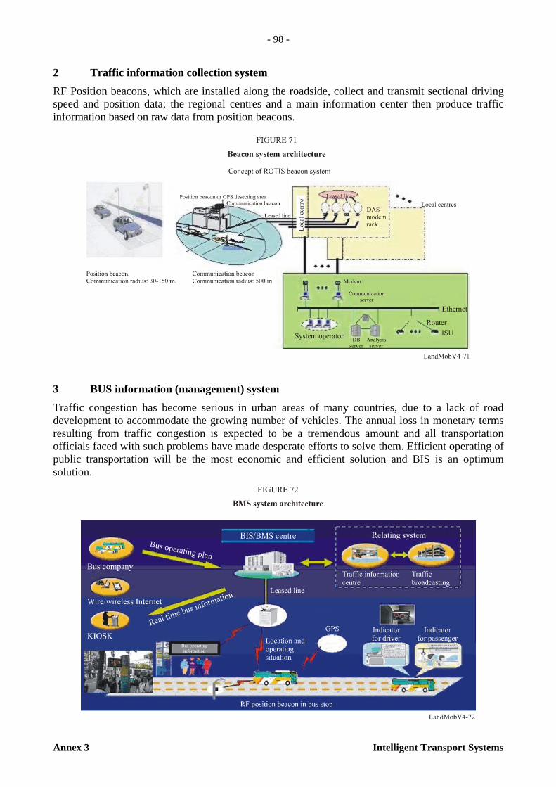
- 98 -
Annex 3 Intelligent Transport Systems
2 Traffic information collection system
RF Position beacons, which are installed along the roadside, collect and transmit sectional driving speed and position data; the regional centres and a main information center then produce traffic information based on raw data from position beacons.
3 BUS information (management) system
Traffic congestion has become serious in urban areas of many countries, due to a lack of road development to accommodate the growing number of vehicles. The annual loss in monetary terms resulting from traffic congestion is expected to be a tremendous amount and all transportation officials faced with such problems have made desperate efforts to solve them. Efficient operating of public transportation will be the most economic and efficient solution and BIS is an optimum solution.

- 99 -
Intelligent Transport Systems Annex 3
4 Specifications
a) Position beacon – A communication device that informs the location information – Function – Broadcasting position information – Specification
– Installed at street light post – Electric source: street light or solar cell – 224.150 MHz (6 channels) – MSK (FFSK) 4 800 bit/s – Transmit radius: 50 m (max) in urban area.
b) In vehicle module (CRF) – Probe car communication device – Function
– 8-bit CPU – Car location detection through PB – Transmitting & receiving communication with RF station – Sensing car moving distance through car VSS signal (Tacho signal) – History making & transmitting – WhereIam transmitting – Calling function and traffic information service
– Specification – 224.025-150 MHz (channel 1-6) – FFSK wireless communication method: 4 800 bit/s – Half duplex method – Electric source: Car electric source – Outside antenna – Connectable with external device through RS-232C (9 600 bit/s).
c) RF station – Station which relay CRF data to traffic information centre – Function
– Both direction wireless communications – Collecting the history, WhereIam packet – Car speed service – Receiver installed at CRF
– Specification – Home power source – 224.0-224.125 MHz send/receive (channel: 0-5) – Output: under 10 MW – MSK(FFSK) 4 800 bit/s – Half duplex method – Sending radius: 500 m (max) – Telephone line modem communication (2 400 bit/s).

- 101 -
Intelligent Transport Systems Annex 4
ANNEX 4
A FUTURE ITS NETWORK ARCHITECTURE: CALM
1 Introduction
The objective of CALM (communications air interface long and medium range) is to support a standardized set of air interface protocols and parameters for medium and long range, high speed ITS communication using one or more of several media, with multipoint and networking protocols within each media, and upper layer protocols to enable transfer between media.
While it may seem desirable to have globally common decisions, regulations and standards for the introduction and operation of ITS services, the heterogeneous nature of wireless networks and the regulatory environment around the world present challenges to those attempting to use those networks for carrying ITS network traffic. In summary, the following challenges and issues need to be addressed:
a) Provide systems that enable (quasi) continuous communications between vehicles and the infrastructure, and between vehicles, in an environment where the vehicle marketplace is global with a limited number of large manufacturers providing vehicle models on a global basis with minimum variation to meet local national requirements.
b) Provide systems, with a useful standardization lifetime of 10-20 years, where vehicles may be operational for 20+ years. Thus, there is a need for systems which will be functioning to 2030 and beyond.
c) The lifecycle of telecommunications systems is getting shorter, and several future possibilities are now apparent, and it is clear that other new technologies, not yet envisaged, may be developed in the period 2005-2040. By 2040, current communications systems, such as 2G and 3G cellular are unlikely to exist as we know them today due to evolution and technology progression. However, it can also be recognized that some evolved IP-based 3G cellular system standards are purposely developed with backward compatibility in mind and currently are deployed for ITS services (including cellular network mobility, public switched telephone network (PSTN) connectivity and ad-hoc-type applications). Their advanced post-3G cellular-based evolutions can also be backward compatible, as able, to the current or near-term cellular systems, thus allowing for one form of evolutionary and functional lifecycle that may span twenty or more years.
d) In different countries there are different wireless systems that are available to support ITS applications.
e) The characteristics of different media vary according to the properties of that media. Different media are better or less well suited to different applications.
f) Vehicles frequently travel cross border and operate in countries other than their home country. This is particularly true for commercial vehicles, and for all vehicles within Europe.
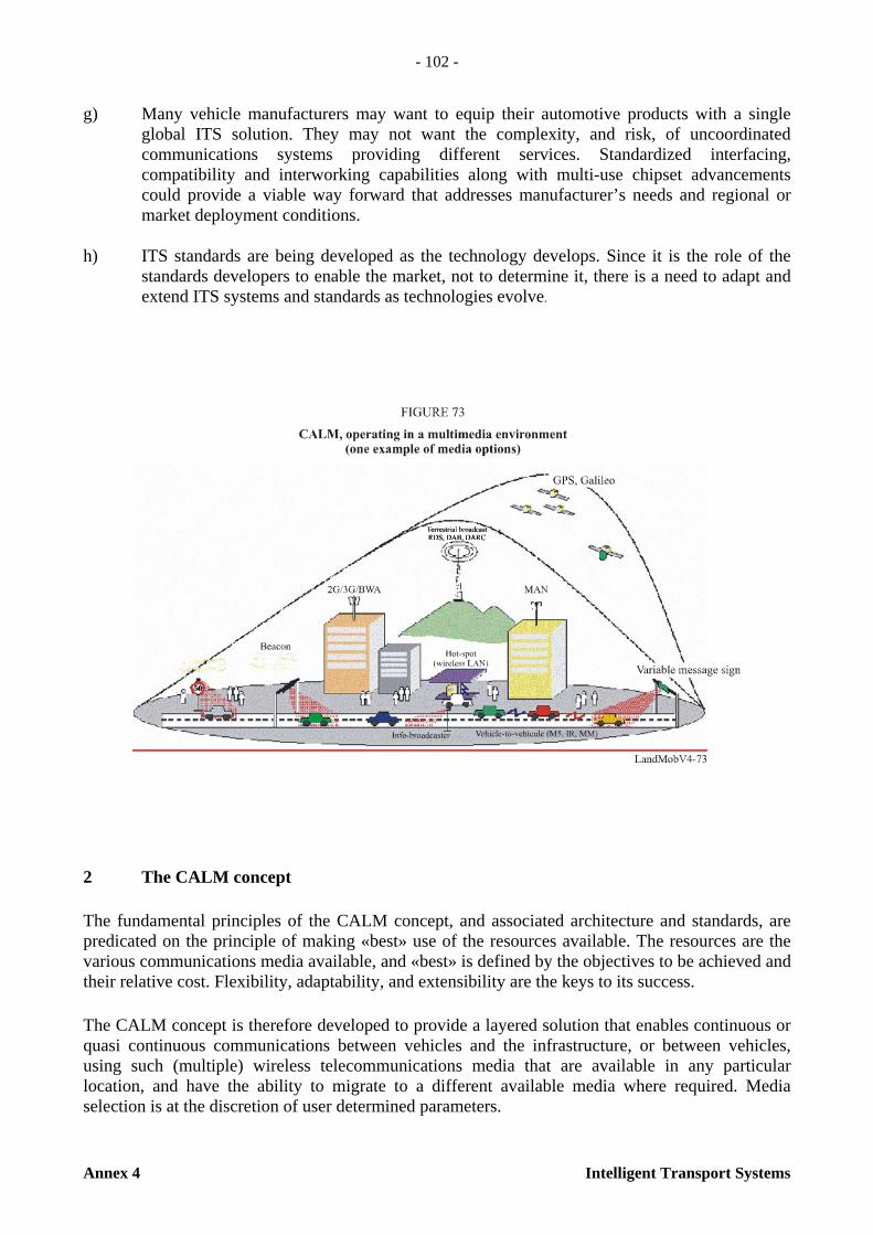
- 102 -
Annex 4 Intelligent Transport Systems
g) Many vehicle manufacturers may want to equip their automotive products with a single global ITS solution. They may not want the complexity, and risk, of uncoordinated communications systems providing different services. Standardized interfacing, compatibility and interworking capabilities along with multi-use chipset advancements could provide a viable way forward that addresses manufacturer’s needs and regional or market deployment conditions.
h) ITS standards are being developed as the technology develops. Since it is the role of the standards developers to enable the market, not to determine it, there is a need to adapt and extend ITS systems and standards as technologies evolve.
2 The CALM concept
The fundamental principles of the CALM concept, and associated architecture and standards, are predicated on the principle of making «best» use of the resources available. The resources are the various communications media available, and «best» is defined by the objectives to be achieved and their relative cost. Flexibility, adaptability, and extensibility are the keys to its success.
The CALM concept is therefore developed to provide a layered solution that enables continuous or quasi continuous communications between vehicles and the infrastructure, or between vehicles, using such (multiple) wireless telecommunications media that are available in any particular location, and have the ability to migrate to a different available media where required. Media selection is at the discretion of user determined parameters.

- 103 -
Intelligent Transport Systems Annex 4
3 CALM service types
Services that are likely to use CALM fall into two categories- safety and commercial, although some safety related services are of commercial interest as options on up market vehicles. The lists given in § 2.2 (see Table 1) provide a selection of services that have already been identified as probably suitable for support via CALM. The list is not exhaustive or complete and continues to expand as ITS evolves. However, it gives an indication of the types of categories of services that may use CALM.
4 CALM benefits
CALM combines and spans multiple communication media, including broadcasting, in an open manner by the integration of a simple IPv6/Management convergence layer, in accordance with international standards:
– Openness, since the standards are available to everybody. CALM combines multiple communication media in an open way
– Stability, since there is a formal body responsible
– Visibility and credibility of the specifications
– An open way to influence the next phases of standards
– Extensibility.
CALM is based on IPv6 (Internet Protocol version 6) which means that it is fully compatible with Internet services, while at the same time not being restricted by the addressing shortcomings of the current IPv4 protocols. (IETF provide solutions to enable IPv4 to operate over IPv6).
5 CALM architecture
The scope of CALM is to provide a standardized set of air interface protocols and parameters for medium and long range, high speed ITS communication using one or more of several media, with multipoint and networking protocols within each media, and upper layer protocols to enable transfer between media.
CALM architecture supports the following communication modes:
– Vehicle-infrastructure: Multipoint communication parameters are automatically negotiated, and subsequent communication may be initiated by either roadside or vehicle
– Infrastructure-infrastructure: The communication system may also be used to link fixed points where traditional cabling is undesirable.
– Vehicle-vehicle: A low latency peer-peer network with the capability to carry safety related data such as collision avoidance, and other vehicle-vehicle services such as ad-hoc networks linking multiple vehicles.

- 104 -
Annex 4 Intelligent Transport Systems
For further information on contents and status of CALM standards and interfaces (shown in the CALM architecture), please refer to the activities in ISO/TC204, CEN TC278, and ETSI ERM TG37.

- 105 -
Intelligent Transport Systems Annex 5
ANNEX 5
LIST OF ACRONYMS
3GPP 3rd Generation partnership program
3GPP2 3rd Generation partnership two program
AACN Automatic crash notification
ACC Adaptive cruise control
ACR Access control router
ADSL Asymmetric digital subscriber loop
AGPS Assisted GPS
AHS Automated highway system
AoA Angle of arrival
ARIB Association of Radio Industries and Businesses
ASK Amplitude shift keying
ASL Application sub-layer
ASTM American Society for Testing and Materials, later ASTM International
ATIS Advanced traffic information service
AVI Automatic vehicle identification
BCMCS Broadcast-multicast service
BER Bit error rate
BIS Bus information systems
BMS Bus management system
BREW Binary runtime environment for wireless
CCTV Closed circuit television
CDMA Code division multiple access
CEN European committee for standardization
CEPT European Conference of Postal and Telecommunications Administrations
CLI Caller line identification
DARC Data radio channel
DB Data base
DCU Data communication unit
DELTA DSRC electronics implementation for transportation and automotive applications
DGPS Differential globe positioning system

- 106 -
Annex 5 Intelligent Transport Systems
DMB Digital multimedia broadcasting
DQPSK Differential QPSK
DSB Digital sound broadcasting
DSL Digital subscriber loop
DSRC Dedicated short range communications
DTTB Digital terrestrial television broadcasting
DVB-H Digital video broadcasting for handheld devices technology
ECC Electronic Communications Committee
EID Entity Identification
EIRP Effective isotropic radiation power
ERC European Radiocommunications Committee
ERI Electronic registration identification
ETC Electronic toll collection
ETSI European Telecommunications Standardization Institute
EU European Union
FA Foreign agent
FCC Federal Communications Committee
FDD Frequency division duplexing
FFT Fast Fourier transform
FLO Forward link only technology
FWA Fixed wireless access
GMLC Gateway mobile location centre
GMSK Gaussian filtered minimum shift keying
GNSS Global navigation satellite system
GPR Ground penetrating radars
GPS Global positioning system
HDLC High-level data link control
HSDPA High speed downlink packet access
IAG Interagency Group
ICT Information and communication technologies
ID IDentification
IEEE Institute of Electrical and Electronics Engineers
IETF Internet Engineering Task Force

- 107 -
Intelligent Transport Systems Annex 5
IMS IP multimedia subsystem
IMT-2000 International mobile telecommunication-2000
IP Internet Protocol
ISM Industrial, scientific and medical
ISO International Organization for Standardization
ITI Intelligent transportation infrastructure
ITS Intelligent transport system
KICT Korea Institute of Construction Technology
KOTI Korea Transport Institute
KRIHS Korea Research Institute of Human Settlements
LAN Local area network
LBS Location based service
LCD Liquid crystal display
LCP Local control protocol
LED Light emitting diode
LMS Location and monitoring service
LMSK Level controlled minimum shift keying
MAC Medium access control
MIC Ministry of Internal Affairs and Communications
MMD Multi-media domain
MMI Man machine interface
MMS Multimedia messaging service
MNO Mobile network operator
MOCT Ministry of Construction and Transportation
MRPI Medium range pre-information
MS Mobile station
NEMO NEtwork MObility
NMS Network monitoring system
NMS Network monitoring system
OBD On-board diagnostics
OBE On-board equipment
OBU On-board unit
OCC OnStar Call Center
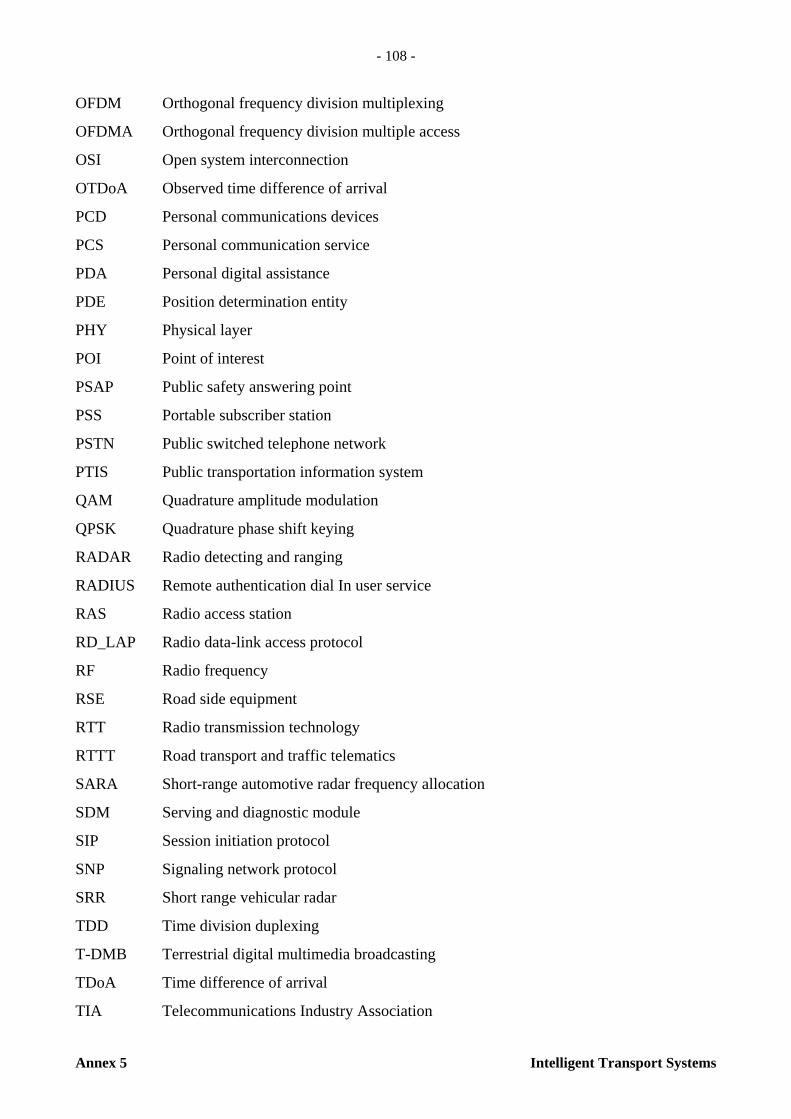
- 108 -
Annex 5 Intelligent Transport Systems
OFDM Orthogonal frequency division multiplexing
OFDMA Orthogonal frequency division multiple access
OSI Open system interconnection
OTDoA Observed time difference of arrival
PCD Personal communications devices
PCS Personal communication service
PDA Personal digital assistance
PDE Position determination entity
PHY Physical layer
POI Point of interest
PSAP Public safety answering point
PSS Portable subscriber station
PSTN Public switched telephone network
PTIS Public transportation information system
QAM Quadrature amplitude modulation
QPSK Quadrature phase shift keying
RADAR Radio detecting and ranging
RADIUS Remote authentication dial In user service
RAS Radio access station
RD_LAP Radio data-link access protocol
RF Radio frequency
RSE Road side equipment
RTT Radio transmission technology
RTTT Road transport and traffic telematics
SARA Short-range automotive radar frequency allocation
SDM Serving and diagnostic module
SIP Session initiation protocol
SNP Signaling network protocol
SRR Short range vehicular radar
TDD Time division duplexing
T-DMB Terrestrial digital multimedia broadcasting
TDoA Time difference of arrival
TIA Telecommunications Industry Association
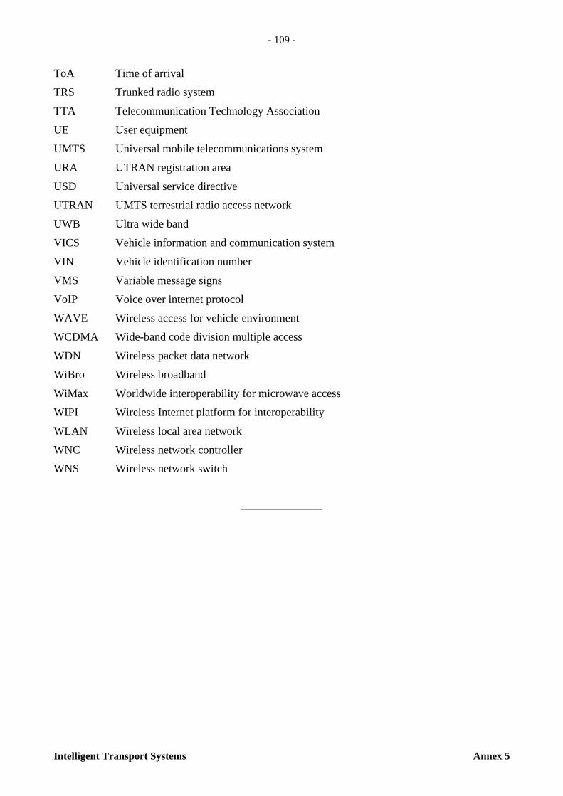
- 109 -
Intelligent Transport Systems Annex 5
ToA Time of arrival
TRS Trunked radio system
TTA Telecommunication Technology Association
UE User equipment
UMTS Universal mobile telecommunications system
URA UTRAN registration area
USD Universal service directive
UTRAN UMTS terrestrial radio access network
UWB Ultra wide band
VICS Vehicle information and communication system
VIN Vehicle identification number
VMS Variable message signs
VoIP Voice over internet protocol
WAVE Wireless access for vehicle environment
WCDMA Wide-band code division multiple access
WDN Wireless packet data network
WiBro Wireless broadband
WiMax Worldwide interoperability for microwave access
WIPI Wireless Internet platform for interoperability
WLAN Wireless local area network
WNC Wireless network controller
WNS Wireless network switch


THE RADIOCOMMUNICATION SECTOR OF ITU
The role of the Radiocommunication Sector is to ensure the rational, equitable, efficient and economical use of the radio-frequency spectrum by all radiocommunication services, including satellite services, and carry out studies without limit of frequency range on the basis of which Recommendations are adopted.
The regulatory and policy functions of the Radiocommunication Sector are performed by World and Regional Radiocommunication Conferences and Radiocommunication Assemblies supported by Study Groups.
Inquiries about radiocommunication matters Please contact:
I T U Radiocommunication Bureau Place des Nations CH -1211 Geneva 20 Switzerland
Telephone: +41 22 730 5800 Fax: +41 22 730 5785 E-mail: [email protected] Web: www.itu.int/itu-r
Placing orders for ITU publicationsPlease note that orders cannot be taken over the telephone. They should be sent by fax or e-mail.
I T U Sales and Marketing Division Place des Nations CH -1211 Geneva 20Switzerland
Fax: +41 22 730 5194 E-mail: [email protected]
The Electronic Bookshop of ITU: www.itu.int/publications
ITU 2007
All rights reserved. No part of this publication may be reproduced, by any means whatsoever, without the prior written permission of ITU.

I n t e r n a t i o n a l T e l e c o m m u n i c a t i o n U n i o n
I n te rnat iona lTe lecommun icat ionUn ion
*30101*Printed in Switzerland
Geneva, 2007ISBN 92-61-11871-2 Radiocommunication Bureau
INTELLIGENTTRANSPORT
SYSTEMS
Handbook onLand Mobile
(including Wireless Access)
Volume 4(Edition 2006)
INT
ELLIG
EN
T T
RA
NS
PO
RT
SY
ST
EM
S
La
nd
Mo
bil
e (
inclu
din
g W
ire
les
s A
cce
ss
) V
olu
me
4 –
Ed
itio
n 2
00
6