Embed Size (px)
Citation preview
Intelligent Mission Management for Uninhabited Aerial Vehicles
Don Sullivan, Joseph Totah, Steve Wegener, Francis Enomoto, Chad Frost, John Kaneshige and Jeremy Frank
NASA Ames Research Center, Moffett Field, CA. 94035
Abstract
The National Aeronautics and Space Administration (NASA), Aeronautics Research Mission Directorate, is developing Intelligent Mission Management (IMM) technology for Uninhabited Aerial Vehicles (UAV’s) under the Vehicle Systems Program’s Autonomous Robust Avionics Project. The objective of the project is to develop air vehicle and associated ground element technology to enhance mission success by increasing mission return and reducing mission risk. Unanticipated science targets, uncertain conditions and changing mission requirements can all influence a flight plan and may require human intervention during the flight; however, time delays and communications bandwidth limit opportunities for operator intervention. To meet these challenges, we will develop UAV-specific technologies enabling goal-directed autonomy, i.e. the ability to redirect the flight in response to current conditions and the current goals of the flight. Our approach divides goal-directed autonomy into two components, an on-board Intelligent Agent Architecture (IAA) and a ground based Collaborative Decision Environment (CDE). These technologies cut across all aspects of a UAV system, including the payload, inner- and outer-loop onboard control, and the operator’s ground station. Keywords: Autonomy, UAV, Sensor Planning Service, Sensor Web, Intelligent Mission Management, Collaborative and Coordinated Systems, Intelligent Autonomous Architecture, Autonomous Robust Avionics 1.0 Anticipated Results The principal result will be a demonstration of the technology in an actual Earth Science Mission; namely the Western States Fire Mission (illustrated in Figure 1). One of the driving objectives of this mission is to demonstrate successful, high altitude data collection by a UAV over a wildfire within National Airspace (outside perimeters of closed test range facilities). The purpose of the ALTAIR Western States Fire Mission is to further demonstrate enhancements to the UAV platform capabilities, improvements to the payload data collection system, telemetry capabilities, and image geo-rectification and data / information decision support system enhancement.
Figure 1. HALE UAV conducts wildfire reconnaissance mission.
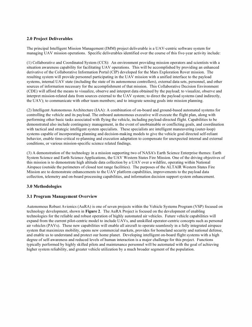
2.0 Project Deliverables The principal Intelligent Mission Management (IMM) project deliverable is a UAV-centric software system for managing UAV mission operations. Specific deliverables identified over the course of this five-year activity include: (1) Collaborative and Coordinated System (CCS): An environment providing mission operators and scientists with a situation awareness capability for facilitating UAV operations. This will be accomplished by providing an enhanced derivative of the Collaborative Information Portal (CIP) developed for the Mars Exploration Rover mission. The resulting system will provide personnel participating in the UAV mission with a unified interface to the payload systems, internal UAV state (including the state of its autonomous controllers), external data sets, personnel, and other sources of information necessary for the accomplishment of that mission. This Collaborative Decision Environment (CDE) will afford the means to visualize, observe and interpret data obtained by the payload; to visualize, observe and interpret mission-related data from sources external to the UAV system; to direct the payload systems (and indirectly, the UAV); to communicate with other team members; and to integrate sensing goals into mission planning. (2) Intelligent Autonomous Architecture (IAA): A combination of on-board and ground-based automated systems for controlling the vehicle and its payload. The onboard autonomous executive will execute the flight plan, along with performing other basic tasks associated with flying the vehicle, including payload-directed flight. Capabilities to be demonstrated also include contingency management, in the event of unobtainable or conflicting goals, and coordination with tactical and strategic intelligent system specialists. These specialists are intelligent maneuvering (outer-loop) systems capable of incorporating planning and decision-making models to give the vehicle goal directed self-reliant behavior, enable time-critical re-planning and execution adaptation to compensate for unexpected internal and external conditions, or various mission-specific science related findings. (3) A demonstration of the technology in a mission supporting two of NASA's Earth Science Enterprise themes: Earth System Science and Earth Science Applications, the UAV Western States Fire Mission. One of the driving objectives of this mission is to demonstrate high altitude data collection by a UAV over a wildfire, operating within National Airspace (outside the perimeters of closed test range facilities). The purposes of the ALTAIR Western States Fire Mission are to demonstrate enhancements to the UAV platform capabilities, improvements to the payload data collection, telemetry and on-board processing capabilities, and information decision support system enhancement. 3.0 Methodologies 3.1 Program Management Overview Autonomous Robust Avionics (AuRA) is one of seven projects within the Vehicle Systems Program (VSP) focused on technology development, shown in Figure 2. The AuRA Project is focused on the development of enabling technologies for the reliable and robust operation of highly automated air vehicles. Future vehicle capabilities will expand from the current pilot-centric model to include UAVs, and unskilled operator-centric concepts such as personal air vehicles (PAVs). These new capabilities will enable all aircraft to operate seamlessly in a fully integrated airspace system that maximizes mobility, opens new commercial markets, provides for homeland security and national defense, and enable us to understand and protect our home planet. Developing intelligent on-board flight systems with a high degree of self-awareness and reduced levels of human interaction is a major challenge for this project. Functions typically performed by highly skilled pilots and maintenance personnel will be automated with the goal of achieving higher system reliability, and greater vehicle utilization by a much broader segment of the population.
Vehicle Systems
(HQ)
Quiet
Aircraft
Technology -
QAT
Integrated
Tailored
Aerostructures
- ITAS
Vehicle Integration,
Strategy & Technology
Assessment (VISTA)
Low
Emissions
Alternative
Power -
LEAP
Flight and System Demonstrations
Ultra
Efficient
Engine
Technology
- UEET
Autonomous
Robust
Avionics -
AuRA
Efficient
Aerodynamic
Shapes and
Integration -
EASI
Strategy
Team
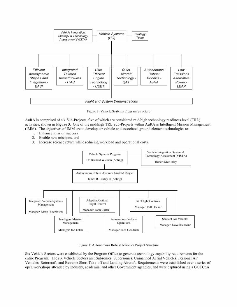
Figure 2: Vehicle Systems Program Structure AuRA is comprised of six Sub-Projects, five of which are considered mid/high technology readiness level (TRL) activities, shown in Figure 3. One of the mid/high TRL Sub-Projects within AuRA is Intelligent Mission Management (IMM). The objectives of IMM are to develop air vehicle and associated ground element technologies to:
1. Enhance mission success 2. Enable new missions, and 3. Increase science return while reducing workload and operational costs
Figure 3: Autonomous Robust Avionics Project Structure Six Vehicle Sectors were established by the Program Office to generate technology capability requirements for the entire Program. The six Vehicle Sectors are: Subsonics, Supersonics, Unmanned Aerial Vehicles, Personal Air Vehicles, Rotorcraft, and Extreme Short Take-off and Landing Aircraft. Requirements were established over a series of open workshops attended by industry, academia, and other Government agencies, and were captured using a GOTChA
Autonomous Robust Avionics (AuRA) Project
James R. Burley II (Acting)
Intelligent Mission
Management
Manager: Joe Totah
RC Flight Controls
Manager: Bill Decker
Manager: W. Decker
Autonomous Vehicle
Operations
Manager: Ken Goodrich
Vehicle Systems Program
Dr. Richard Wlezien (Acting)
Vehicle Integration, System &
Technology Assessment (VISTA)
Robert McKinley
Sentient Air Vehicles
Manager: Dave Richwine
Adaptive/Optimal
Flight Control
Manager: John Carter
Integrated Vehicle Systems
Management
Manager: Mark Hutchinson
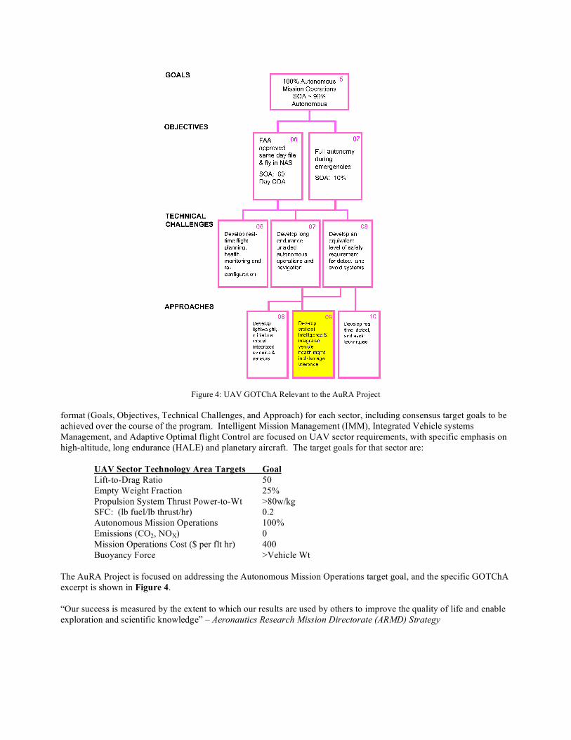
Figure 4: UAV GOTChA Relevant to the AuRA Project
format (Goals, Objectives, Technical Challenges, and Approach) for each sector, including consensus target goals to be achieved over the course of the program. Intelligent Mission Management (IMM), Integrated Vehicle systems Management, and Adaptive Optimal flight Control are focused on UAV sector requirements, with specific emphasis on high-altitude, long endurance (HALE) and planetary aircraft. The target goals for that sector are:
UAV Sector Technology Area Targets Goal Lift-to-Drag Ratio 50 Empty Weight Fraction 25% Propulsion System Thrust Power-to-Wt >80w/kg SFC: (lb fuel/lb thrust/hr) 0.2 Autonomous Mission Operations 100% Emissions (CO2, NOX) 0 Mission Operations Cost ($ per flt hr) 400 Buoyancy Force >Vehicle Wt
The AuRA Project is focused on addressing the Autonomous Mission Operations target goal, and the specific GOTChA excerpt is shown in Figure 4. “Our success is measured by the extent to which our results are used by others to improve the quality of life and enable exploration and scientific knowledge” – Aeronautics Research Mission Directorate (ARMD) Strategy
In light of the ARMD strategy, the IMM Sub-Project funds technology development based on mission-driven requirements from (primarily) the Earth Science community, and has identified the UAV First Response Experiment (FiRE) as a key technology driver from which to extract mission specific requirements to guide technology development, demonstration, and infusion in two key areas: Intelligent/Autonomous Architectures (IAA) and Collaborative and Coordinated Systems (CCS). This approach is designed to tightly couple on-board intelligence with a ground-based collaborative decision environment, perform sub-scale evaluations leading to full-scale validation and actual UAV FiRE mission demonstrations. This approach is considered an important first step to enabling new missions, including the next generation of HALE UAV’s designed to stay aloft for weeks and months, and also future planetary flight vehicles designed to explore Mars and potentially other planets with atmospheric conditions conducive to flight.
3.2 System Overview A UAV system consists of numerous complex components that must seamlessly interact in order to meet its objectives. The payload is often a sensitive instrument with complex operating modes that generates considerable volumes of data in a short time. The payload is often developed independently of the UAV that carries it, resulting in complex interfaces between instruments and vehicles. While piloted aircraft have a long history, UAVs are relative newcomers to aviation, with autonomous aircraft slowly joining teleoperated vehicles in flight. These vehicles are difficult to control from a distance with time delays, and only become more complex when delicate payloads are added to them. Communication links are required to transmit the current state of the vehicle as well as payload data to operators. Once this data is on the ground, operators must be able to sort through the data in a timely manner to interpret the data, and decide whether or not to issue new commands. Achieving reduction in operator workload and corresponding increase in mission return for such highly interconnected UAV systems requires advances on a number of fronts. Enabling autonomous operation of both the payload and the UAV itself will reduce the need to transmit large data volumes to the operator, reduce the decision making burden for the operator, and increase mission return by reacting to uncertainty without the time delays incurred by “phoning home”. Autonomous payload operations include the ability to track “interesting” phenomena and automatically analyze payload data without human intervention. Autonomous UAV operations include intelligent avionics as well as outer-loop autonomy. On the ground, challenges include user interface design to promote rapid operator situational awareness, as well as automation to enable rapid operator-driven “what-if” analysis that may be computationally impossible for the on-board system. Finally, systems integration is required to ensure that these complex components interoperate correctly. Generally speaking, the IAA component of our solution is concentrated on the vehicle, while the CCS is concentrated on a ground station through which the human operator controls the vehicle. However, the CCS and IAA manifest themselves in each component of the UAV system. For this reason, in the following sections, we will describe the approach by discussing each facet of the UAV system in turn. 3.3 Ground Control and Human Interfaces Ground control is provided through the science mission and vehicle operator interfaces. The Collaborative Decision Environment (CDE) is the ground system that provides the UAV team with situational awareness, collaboration, and decision-making tools to accomplish their mission. It will be used to support pre-flight planning, monitoring mission schedules, direct the payload system, visualization, and integrate sensing goals into the mission planning. While the CDE is primarily the science mission interface, it also communicates with the UAV operator interface and shares vehicle situational awareness, health monitoring, onboard decision monitoring. The current client/server software architecture is derived from the Collaborative Information Portal (CIP) developed for the Mars Exploration Rover mission.1 Using CIP with a custom-built interface designed specifically for the Mars
1 Walton, J. D., et al., “Collaborative Information Portal: MER and Beyond,” Proc. of International Conference on Space Mission Challenges for Information Technology, Pasadena, CA, July 15-16 2003.

mission, team members could immediately access reports, images, daily schedules or mission plans stored in a variety of databases. CIP was implemented in Java in order to support a variety of computer platforms. Capabilities such as secure remote access, portability, managing heterogeneous data, viewing schedules, and broadcasting messages will be enhanced to meet the needs of UAV missions. A prototype UAV version of the CDE was developed in which the impact of higher frequency data message broadcasting on the current middleware and graphics performance due to constantly accessing remote GIS data on the client are being evaluated. All payload data products generated by a mission will be accessed from the CDE. Since the CDE provides data management, archived data from previous missions can be retrieved to compare against the current mission. In addition, external data products used in planning a mission such as weather, satellite data products, and topographic maps will be provided. Since many Earth science data products are geospatially oriented, the CDE will be able to leverage the open standards developed by the Open Geospatial Consortium (OGC) to acquire external data products. The CDE provides situational awareness, visualization, and decision support through several methods. The current schedule monitor can display Gantt style ground-based and onboard activities and will be enhanced to dynamically display automated re-planning. Currently, vehicle position and sensor images can be spatially projected as graphic layers over 2-dimensional orthographic maps or aerial or satellite ortho-imagery (e.g. Landsat,). 3-dimensional visualization tools such as the Space-time Toolkit that are capable of fusing multiple scientific data sets with disparate spatial and temporal representations will be integrated with the CDE to enhance its decision support capability.2 The operations team may be geographically distributed, so the CDE is capable of providing distributed access to remote locations across wide area networks. Since the CDE is a distributed system that allows remote users to interact with sensors aboard the UAV, secure protocols are required to prevent unauthorized access. Furthermore, an authorization scheme is required to distinguish roles between users allowed to monitor and view data products and those who can provide commands that direct the payload system (and indirectly the UAV). The CDE is expected to provide a real-time or near-real-time access to the payload systems, although the level at which the data is available may be very dependent on the particular mission. This becomes technically challenging since there are several communication paths that must be traversed including the UAV to ground station, ground station to CDE servers, and CDE servers to CDE clients, the last two probably across wide area networks. Onboard processing may allow summaries or samplings of sensor data products to reduce the bandwidth requirements. CCS and IAA are tightly coupled in the ground control environment. The CDE will provide a user interface to a sensor planning service which will allow personnel on the ground to query the capabilities, status, and request data from sensors aboard the UAV. The simplest tasking command would allow a user to request the sensor to immediately return the current or last stored measurement or processed data product. If the sensor were controllable, then another type of command would be to request the sensor to reconfigure itself in preparation a future measurement. A more complex command would be to request data at set of locations or times in the future, possibly with constraints like priorities or orientation of the aircraft or sensor, and to notify the user when the data is available. This becomes a sensing goal that must be incorporated in the overall mission plan, either prior to or during flight. Assuming there is no limit on who is authorized to request a sensor goal, then several users making individual sensor goals from a limited resource will require planning to achieve as many sensor goals within given constraints. An example of an automated planning tool is MAPGEN (Mixed Initiative Activity Planning Generator), a ground-based decision support system used in the MER mission.3 MAPGEN is known as a mixed initiative planner that ”mixes” human interaction with the advanced planning software. The paradigm is to enable the person using the software to critique a plan that the system automatically produces and ensure that resulting plans are viable within mission and flight rules. MAPGEN will determine that the plan is within the bounds of the available resources onboard the UAV, 2 Botts, M. and R. Phillips, “ Improved Space-Time Visualization and Analysis for Disparate Earth-System Data,” 12th International Conference on Interactive Information and Processing Systems for Meteorology, Oceanography, and Hydrology, American Meteorology Society, Atlanta, Jan. 28-Feb. 2 1996. 3 Ai-Chang, M., et al., “MAPGEN: mixed-initiative planning and scheduling for the Mars Exploration Rover mission”, IEEE Intelligent Systems, vol. 19, issue 1, pp. 8-12, Jan.-Feb. 2004.
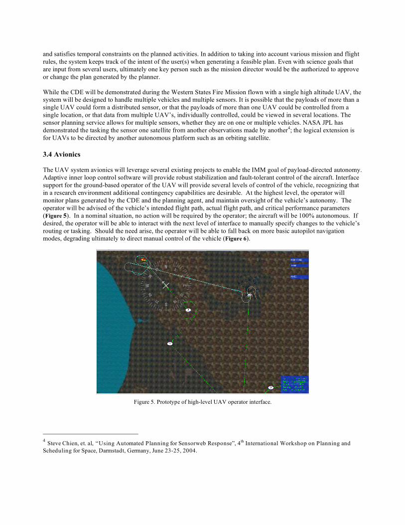
and satisfies temporal constraints on the planned activities. In addition to taking into account various mission and flight rules, the system keeps track of the intent of the user(s) when generating a feasible plan. Even with science goals that are input from several users, ultimately one key person such as the mission director would be the authorized to approve or change the plan generated by the planner. While the CDE will be demonstrated during the Western States Fire Mission flown with a single high altitude UAV, the system will be designed to handle multiple vehicles and multiple sensors. It is possible that the payloads of more than a single UAV could form a distributed sensor, or that the payloads of more than one UAV could be controlled from a single location, or that data from multiple UAV’s, individually controlled, could be viewed in several locations. The sensor planning service allows for multiple sensors, whether they are on one or multiple vehicles. NASA JPL has demonstrated the tasking the sensor one satellite from another observations made by another4; the logical extension is for UAVs to be directed by another autonomous platform such as an orbiting satellite. 3.4 Avionics The UAV system avionics will leverage several existing projects to enable the IMM goal of payload-directed autonomy. Adaptive inner loop control software will provide robust stabilization and fault-tolerant control of the aircraft. Interface support for the ground-based operator of the UAV will provide several levels of control of the vehicle, recognizing that in a research environment additional contingency capabilities are desirable. At the highest level, the operator will monitor plans generated by the CDE and the planning agent, and maintain oversight of the vehicle’s autonomy. The operator will be advised of the vehicle’s intended flight path, actual flight path, and critical performance parameters (Figure 5). In a nominal situation, no action will be required by the operator; the aircraft will be 100% autonomous. If desired, the operator will be able to interact with the next level of interface to manually specify changes to the vehicle’s routing or tasking. Should the need arise, the operator will be able to fall back on more basic autopilot navigation modes, degrading ultimately to direct manual control of the vehicle (Figure 6).
Figure 5. Prototype of high-level UAV operator interface.
4 Steve Chien, et. al, “Using Automated Planning for Sensorweb Response”, 4th International Workshop on Planning and Scheduling for Space, Darmstadt, Germany, June 23-25, 2004.
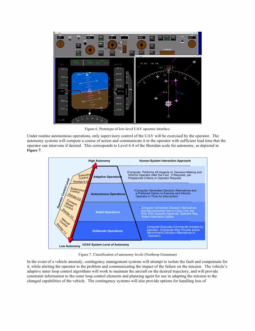
Figure 6. Prototype of low-level UAV operator interface.
Under routine autonomous operations, only supervisory control of the UAV will be exercised by the operator. The autonomy systems will compute a course of action and communicate it to the operator with sufficient lead time that the operator can intervene if desired. This corresponds to Level 6-8 of the Sheridan scale for autonomy, as depicted in Figure 7.
UCAV System Level of Autonomy
Deliberate Operations
Aided Operations
Autonomous Operations
Adaptive OperationsExecutive
Control
•Computer Executes Commands Initiated byOperator. (Computer May Provide and/orRecommend Decision Alternatives toOperator)
•Computer Generates Decision Alternativesand Recommends One to Carry Out – butOnly With Operator Approval. Operator MaySelect Alternative Option
•Computer Generates Decision Alternatives anda Preferred Option to Execute and InformsOperator in Time for Intervention
•Computer Performs All Aspects of Decision-Making andInforms Operator After the Fact, if Required, perPreplanned Criteria or Operator Request
SupervisoryControl
Human-System Interaction Approach
ConsentBasedControl
Manual
Control
Op
era
tor
Co
ntr
ol L
evel
Low Autonomy
High Autonomy
Sheridan 9-10
Sheridan 6-8
Sheridan 3-5
Sheridan 1-2
Figure 7. Classification of autonomy levels (Northrop Grumman)
In the event of a vehicle anomaly, contingency management systems will attempt to isolate the fault and compensate for it, while alerting the operator to the problem and communicating the impact of the failure on the mission. The vehicle’s adaptive inner loop control algorithms will work to maintain the aircraft on the desired trajectory, and will provide constraint information to the outer loop control elements and planning agent for use in adapting the mission to the changed capabilities of the vehicle. The contingency systems will also provide options for handling loss of

communications; these will include protocols for continuing the mission while attempting re-establishment of communications, flight to a safe holding area, and ultimately termination of the flight in a controlled way. 3.5 Autonomous Operations
The UAV autonomy architecture is adapted from autonomous agent architectures commonly used for other NASA applications (e.g. the Deep Space 1 Remote Agent)1. Such agents are designed using a “sense-think-act” closed loop control paradigm. Agents sense their environment and determine what “state” they are in; this includes both external factors such as location and altitude, as well as internal factors such as state of communications, fuel load, and the state of repair of critical components. Agents may receive new goals from their operators, state updates from other UAVs, or commands to perform new actions from the operator. Agents then analyze the goals they have been asked to achieve (e.g. locate a fire near an approximate location) and determine how to accomplish these goals. At times, the agent may have a plan of action ready, but at other times (e.g. after being asked to accomplish a new goal or given an override command) they may need a new plan. In order to handle uncertainty about either the state of the world or the results of their actions, agents may build several plans for different contingencies. Agents then perform actions in order to execute the plan. Feedback from those actions determines the next state, at which time the loop begins again.
As mentioned in Section 3.0.3,the task of instantiating this architecture for a UAV requires dividing functionality
between the payload, the vehicle, the ground station, and the human operators. For example, a UAV may have enough processing power onboard to develop long-range plans to achieve general goals, but may not be able to analyze sensor data. In this case, sensor data is sent to the ground station for resource-intensive processing and analysis by the operator. As another example, UAVs with little on-board processing power may not be able to perform many autonomy functions on their own. In this case, long-range planning must be performed at the ground station, with humans taking on the most general and abstract decision-making tasks. Much of this basic autonomy architecture is common across sensors, UAVs and missions, and can therefore be reused for different UAV systems. Autonomy software reuse is also promoted by the use of “models” that describe system operations; such a system was used by the Remote Agent 5.
Our chosen autonomy architecture is based on APEX6, a general-purpose autonomy system that has been used to model such diverse systems as autonomous helicopters and humans performing tasks such as monitoring air traffic control systems. APEX users write reusable models consisting of standard procedures and the conditions under which they are used. For example, a UAV may not be able to use its sensors while banking due to vibration or pointing; such limitations are captured by APEX procedures. During operations, the APEX control system determines which of the applicable procedures to use, commands the underlying system using the rules outlined in the chosen procedure, and continuously updates the set of applicable procedures in response to sensor input.
To date, we have demonstrated an APEX agent that controls a UAV in flight based on simulated sensor feedback for the Western States Fire Mission. Specifically, the agent constructs an initial sequence of waypoints the UAV will visit in order to search for fires at pre-determined locations based on their importance as specified by a human controller. As the true location of the fire is uncertain, the UAV may need to revise its plan upon detection of a fire. Furthermore, the human controller may add or remove goals during the UAV’s flight. The APEX agent is able to revise its plans in the face of such changes. Our current system simulated the interaction of APEX with both the underlying avionics of the UAV as well as the payload autonomy system.
5 N. Muscettola and P. Pandurang Nayak and B. Pell and B. Williams. Remote Agent: to Boldly Go where no AI system has gone before, Artificial Intelligence, 103(1-2):5 – 48, 1998 6 Whalley, M and Takahashi M. and Schulein G. and Freed M. and Christian D. and Patterson-Hine A. and Harris, R. The NASA/Army Autonomous Rotorcraft Project, Proceedings of the American Helicopter Society 59th Annual Forum, 2003.
3.6 Sensor and Payload The sensor and payload design will continue and build on a long history designing and building sensors and integrated payloads for numerous UAVs. Additional leverage will come from lessons learned in designing Earth based Geographic Information System (GIS) data distribution networks, and in implementing Open Standard specifications with organizations like the Open Geospatial Consortium (OGC) and the Federal Geographic Data Committee (FGDC). Open standards and protocols are being utilized to the greatest degree possible, leveraging industry and government efforts to standardize mechanical, electrical and software interfaces. Implementations to date have utilized custom interfaces developed for specific missions, with the concomitant inefficiency and overhead. Payloads typically have contained, as standard, in-flight command and control; most additionally implemented a rudimentary form of autonomous operation. System health monitoring has also been universally implemented, with status information constantly available to the instrument operator(s). Two implementation phases have been defined, each building on lessons learned during actual flight deployments and parallel laboratory efforts. Phase one will utilize the prototype CDE to command the science sensor payload over two distinct mechanisms, or levels of control. One mechanism involves a secure, interactive, human in the loop channel, over a low bandwidth line-of-sight C band link. The second will be an experiment using the high bandwidth, satellite based Ku link. This task will utilize the Consultative Committee for Space Data Systems (CCSDS) network protocol standard defined by the Advanced Orbiting System Space Communications Protocol Specification Blue Book (CCSDS 714.0-B-1 7), to accommodate the high bandwidth, long latency characteristics of geosynchronous satellite communications. Phase one also features a payload capable of onboard data reduction, geo-processing and feature detection. A prototype web service, necessary to enable a sensor planning system, will also be developed. Key technologies identified to date include the Common Alerting Protocol (CAP 8) currently being tested by the Federal Emergency Management Agency (FEMA) and the State of California Office of Emergency Services (CalOES), and the Sensor Model Language (SML 9), an OGC proposed standard, developed primarily at the University of Alabama in Huntsville. The Phase Two implementation has two primary objectives. The first objective will be the complete implementation of a sensor planning service, featuring the ability to schedule tasks, and respond with both planned and unplanned requests for information. Additionally, this phase will fully implement a reprogrammable sensor command handler, derived from satellite design methodologies.10 (Which were, in turn derived from Central Processing Unit (CPU) designs as they evolved from bit-slice to Complex Instruction Set Computer (CISC) and Reduced Instruction Set Computer (RISC) look-up tables and decoders) This will implement a high degree of sensor reconfigurability, robust command decoding and handling, and resistance to space-borne noise-induced command corruption. The telecommand channel service (Telecommand Channel Service Blue Book, CCSDS 201.0-B-3 11) is the service specification currently proposed for intra- and inter-system communication.
7 http://www.ccsds.org/CCSDS/documents/714x0b1.pdf 8 http://www.oasis-open.org/committees/download.php/6334/oasis-200402-cap-core-1.0.pdf 9 http://vast.uah.edu/SensorML/ 10 Berget, Richard T. 1999. Space Mission Analysis and Design. El Segundo, California: Microcosm Press 11 http://www.ccsds.org/CCSDS/documents/201x0b3.pdf
3.7 Closing the Loop on the Payload Different scenarios (including the payload and mission objectives) may require different techniques for closing the loop around the sensors. Some situations may call for direct closed-loop sensor feedback, such as tracking (or pointing) to an object (or image). In these cases, feedback from the sensors would directly affect how the vehicle behaves. For example, if the science return is maximized when a particular object (or feature) is centered within the sensor's field of view, the control system would take that into account when controlling the vehicle's attitude. Methods such as optimal control can be used to weigh the benefit of increased science return against other flight safety issues. Other situations may call for tactical planning, such as maintaining a certain attitude when passing over an object. In these cases, it may be necessary to momentarily sacrifice science return, in order to configure the aircraft for increased science return a few seconds from now. Methods such as data-based model prediction can be used to build a model of the science return based on previous feedback. As a result, the vehicle can adapt to current conditions in order to increase science return as it flies. Still other situations may require intermediate strategic planning, such as turning around to make another pass flying over an object (at the same or different altitude). In these cases, feedback from the sensors can be used to determine high science return areas seen in the previous pass. As a result, the aircraft can plan a trajectory that takes it through those high return areas, while potentially varying other parameters (such as altitude). Some situations may call for strategic planning to handle new or unanticipated science goals. One way this can happen is if the UAV receives a new goal from an operator or another UAV. This can also happen if unexpected,. interesting features are found in the sensor data. In the case of novel features, the UAV must consider whether the new feature constitutes a new goal. In either case, the UAV now has to revise its plan to account for the new goals as well as the previous goals. Finally, some situations call for modifying plans in response to poor quality data or other “failures”. For example, data collected from a pass may be of poor quality due to obscuring smoke, excess aircraft jitter, or poor image angle. Alternatively, poor quality wind prediction may result in more (or less) fuel consumed between science targets. Finally, communication links may be spotty or fail, resulting in failure to communicate science data. In these cases, the UAV must revise its plan to account for the unexpected new state, even though the goals may not have changed. 4.0 Conclusion This paper described the overall approach to technology development taken by the Intelligent Mission Management project, from mission-driven requirements extracted from NASA’s Science Mission Directorate, to functional requirements associated with the air vehicle, payload, science mission interface, and operator interface. The technology developed will contribute to planetary science and crisis response here on Earth by increasing science return while reducing workload and operational costs, as well as enhancing productivity of missions to explore other worlds.