Embed Size (px)
Citation preview
318 IEEE TRANSACTIONS ON INTELLIGENT TRANSPORTATION SYSTEMS, VOL. 13, NO. 1, MARCH 2012
Intelligent Environment-Friendly Vehicles:Concept and Case StudiesKeqiang Li, Tao Chen, Yugong Luo, and Jianqiang Wang
Abstract—The concept of an intelligent environment-friendlyvehicle (i-EFV) is proposed in this paper. It integrates threecomponents, i.e., clean-energy powertrain, electrified chassis, andintelligent information interaction devices. By employing suchtechnologies as structure sharing, data fusion, and control coor-dination, more comprehensive performances are achievable, interms of traffic safety, fuel efficiency, and environmental pro-tection. Based on its definition and configuration, some keytechnologies, including design for resource effectiveness, drivingenvironment identification, and coordinated control, are studied.As a basic application, a platform of an intelligent hybrid electricvehicle (i-HEV), which incorporates a hybrid powertrain withadaptive cruise control, has been designed and implemented. Bothsimulation and experimental results demonstrated that the i-EFVperformed better than a conventional vehicle.
Index Terms—Control coordination, data fusion, intelligentenvironment-friendly vehicle (i-EFV), intelligent hybrid electricvehicle (i-HEV), structure sharing.
I. INTRODUCTION
SUCH SOCIAL concerns related to traffic safety, fuel ef-ficiency, and environmental protection have rapidly been
increasing in recent years. To systematically solve these prob-lems, a certain approach combines intelligent transportationsystems (ITSs) and clean-energy vehicles [1]–[3] for roadvehicles. Today, great progress has been made in the twofields separately, but progress regarding their integration is stillinsufficient. In terms of clean-energy vehicles, most researchesfocus on hybrid electric vehicles (HEVs) [4], [5], fuel cellvehicles [6], [7], and pure electric vehicles [8], [9]. For ITSs,advanced safety technologies such as collision warning [10],[11], collision prevention [12], [13], and autonomous driving[14], [15] have been widely studied.
The ITS technology mainly seeks to improve ride com-fort and traffic safety, whereas clean-energy vehicles aim atmitigating the energy crisis. Their integration should achievecomprehensive vehicular performances on traffic safety, ride
Manuscript received September 29, 2010; revised July 17, 2011 andSeptember 1, 2011; accepted September 18, 2011. Date of publicationOctober 29, 2011; date of current version March 5, 2012. This work wassupported by the National Science Foundation of China under Grant 50975155.This work was supported by the First Automobile Works (FAW) researchcenter. The Associate Editor for this paper was L. Li.
The authors are with Tsinghua University, Beijing 100084, China (e-mail:[email protected]).
Color versions of one or more of the figures in this paper are available onlineat http://ieeexplore.ieee.org.
Digital Object Identifier 10.1109/TITS.2011.2170680
comfort, fuel efficiency, and environmental protection. Further-more, this would make mutual promotion; the ITS can furtherimprove energy management of clean-energy systems, whereaselectricity with fast response can increase system responseand enhance safety. Take the adaptive cruise control (ACC)system used in HEVs as an example: A hybrid powertrainusually responds to the driver’s demands more accurately andfaster, which enhances traffic safety and ride comfort; at thesame moment, ACC provides traffic situation and enablesflexible automation to HEVs, which potentially improves fuelefficiency.
There have been some elementary research results on thisconcept since 2007. The energy management strategy ofhybrid powertrains combined with Global Positioning Sys-tem (GPS)/Geographic Information System was studied in[16] and [17]. Toyota launched the first HEV with an ACCsystem-LS600hl in 2007 [18], and it was also the first toadd driver-assistance systems to HEVs. Based on GPS andtrajectory programming, Zloki from Aachen University dis-cussed the strategy of ACC on HEVs; fuel consumption isreduced by 6.3% compared with the average driver [19].Van Keulen from Eindhoven University also proposed a pre-dictive cruise control strategy on HEVs, and reasonable fuelimprovement was achieved [20]. However, not many studieshave involved the full combination of driver-assistance systemsand hybrid powertrains with the perspective of systematicallyimproving traffic safety, fuel efficiency, and environmentalprotection.
As a promising solution to the comprehensive requirements,a new conceptual intelligent environment-friendly vehicle(i-EFV) is proposed here. It integrates such components asclean-energy powertrain, electrified chassis, and intelligentinformation interaction devices. It employs the technologiesof structure sharing, data fusion, and control coordinationand can achieve better environment-friendly performance withregard to traffic safety, fuel efficiency, and environmentalprotection [21].
This paper is organized as follows. Section II introduces theconfiguration of i-EFVs. In Section III, based on the definitionof i-EFV, three key technologies are presented, which are thebases of guaranteeing an environment-friendly performance.In Section IV, as the basic application to investigate i-EFVs,the platform of an intelligent HEV (i-HEV) that incorporates ahybrid powertrain with a driver-assistance system is designedand put into implementation. Then, simulations based on aforward simulation model and experiments using a prototypecar are performed. The results validate the good feasibility ofi-EFVs, and the vehicle equipped with such systems shows
1524-9050/$26.00 © 2011 IEEE

LI et al.: INTELLIGENT ENVIRONMENT-FRIENDLY VEHICLES: CONCEPT AND CASE STUDIES 319
Fig. 1. Configuration of an i-EFV.
better performance on traffic safety, fuel efficiency, and envi-ronmental protection than conventional intelligent vehicles (IV)and HEVs.
II. CHARACTERISTICS AND CONFIGURATION OF
INTELLIGENT ENVIRONMENT-FRIENDLY VEHICLES
In this paper, we focus on an integrated configuration dueto the consideration of both comprehensive performance andsystem reliability. The following context first introduces thedesign of i-EFV’s configuration, and then, the components andfunctions of each subsystem are analyzed.
As shown in Fig. 1, the i-EFV is composed of three systems:1) intelligent information interaction devices (i-IID); 2) clean-energy powertrain; and 3) electrified chassis.
The i-IID aims at full-scale identification of drive environ-ment, as well as realizing real-time communication amongi-EFVs, infrastructures, and surrounding vehicles. Three sub-systems including onboard sensors, wireless communication ofvehicle-to-vehicle (V2V), and vehicle-to-infrastructure (V2I)communication constitute the i-IID. The onboard sensor sub-system is composed of a digital camera, millimeter-wave radar,GPS, gyrosensor, and accelerometer, and such data as vehiclestatus, intervehicle states, and road-vehicle relative motioncould be obtained by their measurements. To build a full viewof the drive environment, V2V and V2I communication areboth integrated, and following information is communicated,including surrounding vehicle states and traffic information,i.e., preceding traffic flow, traffic lights, and emergent trafficinformation.
The clean-energy powertrain outputs the driver’s requiredpower by balancing multiple power flows. It integrates a cleanpropulsion system and an efficient energy storage system. Theclean propulsion could be any clean power system such ashybrid, pure electric, or fuel cell. To store and buffer thedynamic power, a high-voltage power battery pack and supercapacitor are integrated.
Through longitudinal, lateral, and vertical dynamics control,the electrified chassis emphasizes achieving safe and comfort-able vehicle motion; thus, three systems, i.e., steer-by-wiresystem, electric control suspension, and electric-hydraulicbrake, are assembled.
III. KEY TECHNOLOGIES OF INTELLIGENT
ENVIRONMENT-FRIENDLY VEHICLES
The i-EFV is designed to not only guarantee environment-friendly performance but to seek a solution to achieve betterperformance on traffic safety, fuel efficiency, and environmentalprotection as well. However, it brings much difficulty on systemdesign and coordinated control. During this systematic designprocess, the i-EFV faces three challenges.
1) Complicated configuration. The i-EFV combines multi-source power, hydraulic-electric braking, electric controlsuspension, a steer-by-wire system, V2V and V2I, and anonboard sensor system. For the aforementioned complexconfiguration, abundant structures are coupled or evenredundant. This makes great wastes and increases systemcost. Consequently, the systematic method and optimizedtheory on structure simplifying and sharing needs to bedeeply investigated.
2) Abundant and usually redundant driving information.One of the representative characteristics of the i-EFVis the full-scale identification on traffic environment andvehicle states. However, the amount of information fromV2V, V2I, and onboard sensors is plentiful and often re-dundant. Therefore, it becomes a big problem to processand analyze this information, and then recognize andpredict vehicle states and traffic environment. The theoryof multiinformation fusion specifically on i-EFV shouldbe studied.
3) Complex optimal coordinated control. First, the i-EFVfocuses on comprehensive environment-friendly perfor-mances. Second, the operation functions of i-EFV, whichinclude driver operation, longitudinal/lateral driver as-sistance, and motion stability with regard to driver–vehicle–road interaction, vary along with different driverrequirements and driving conditions. Meanwhile, thei-EFV couples mechanical, electric, and hydraulic sys-tems, and the systems need to be coordinated. Hence,complete control architecture and control theory shouldbe established and studied from the perspective of multi-ple objectives, various functions, and coupling systems.
Consequently, facing above challenges, the i-EFV needs tobe designed from a systematic perspective, and it has threekey technologies including structure sharing, data fusion, andcontrol coordination. Structure sharing is to solve the problemsof system structure integration, simplification, and optimiza-tion. Data fusion focuses on signal processing and mergingfrom separate sensors to construct and predict the completedriver–vehicle–road environment. Control coordination seeksto operate different actuators by the considerations of trafficsafety, fuel efficiency, and environmental protection. More de-tails will be discussed in the succeeding sections.
A. Structure Sharing
Structure sharing is the fulfillment of several functions orfunctional properties with the same physical structure [22],[23]. It is first presented in computational application andthen brought into product design (e.g., sensor design). Many
320 IEEE TRANSACTIONS ON INTELLIGENT TRANSPORTATION SYSTEMS, VOL. 13, NO. 1, MARCH 2012
researchers have emphasized the importance of structure shar-ing, particularly for electromechanical systems. However, therehas been no achievement for such complex system design.Representing the next-generation vehicle, the i-EFV combinessophisticated and redundant structures, and thus, structuresharing will be very useful and necessary to improve sourceeffectiveness and lower total cost.
Consequently, the theory and systematic approach of struc-ture sharing need to be developed more on how to realizethe most system functions with highest efficiency for complexstructures at the lowest cost. Three substructure-sharing tech-nologies are proposed in this paper:
1) Structure sharing of the actuator’s level, which solvesthe problems of optimal structure integration andoptimization with a complicated mechatronical system.Based on the classification of driving functions, thestructure sharing specifically for the i-EFV designcould be decomposed into several substructure-sharingtechnologies for propelling and braking, active steeringand suspension, and, furthermore, the structure sharingof coupled propelling/braking/steering/suspension.Structure-sharing technology follows the principle of“decouple-synthesize.” Some key problems for structure-sharing design of the i-EFV are listed as follows:a) redefinition and decomposition of complex system
functions;b) development of solution principles and structural
representation based on decoupled functions;c) multifunctional structure integration and optimization;d) testing and evaluation on resource effectiveness.
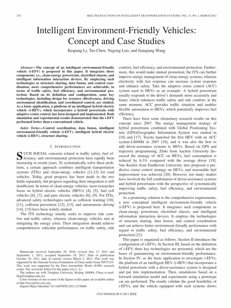
In addition, such properties as manufacturability, life-span, flexibility, and extended functionality should alsobe taken into consideration, and tradeoffs should be madeamong these requirements.1) Information sharing of the multisensor level, which
aims at the simplification of the sensor system onthe basis of onboard sensors and V2V and V2I com-munication. As shown in Fig. 2, various sensors arecombined in the i-EFV, and these sensors provideredundant information. This potentially enables newways to decrease the number of sensors, even theinvention of new sensor, which may take the placeof the original sensor. During this process, assessmentof reliability, cost, as while as redundancy need to beimplemented.
2) Structure sharing in the coordinated-control level,which focuses on incorporating control problems ondifferent drive functions with the same actuators.
Since various driving functions, such as driver operation,longitudinal/lateral driver assistance, and motion stability withregard to driver–vehicle–road interaction, are needed to beintegrated, a flexible and reliable communication network andhierarchical architecture for control should be designed.
In this paper, a conceivable scheme is shown in Fig. 3. Allcontrollers of powertrain, brake, steering, suspension combinedwith diagnostic system, i-IID, and coordinated controller areconnected through controller–area network (CAN) bus. An-
Fig. 2. Structure sharing of multiple sensors.
Fig. 3. Structure sharing of coordinated control.
other key feature is that systems such as powertrain and brakeare decoupled into controllers and actuators, which enhanceflexible coordinated control of different driving functions.However, no credible system has been designed, and there areseveral problems that need to be deeply investigated: 1) how toensure the mechanical connection of driver with electronicallycontrol reliable and stable and 2) how to define the interface ofcoordinated control and actuator control.
B. Data Fusion
Accurate and intact information about vehicle status andtraffic environment plays an important role in supporting co-ordinated control with regard to traffic safety, fuel efficiency,and environmental protection. Generally, there are two issuesin information identification for the i-EFV: 1) The parametersof vehicle status and driving environments are complicatedand time varying, and the sensor system suffers serious dis-turbances, e.g., illumination change for digital camera andelectrical noise for accelerometer. 2) Precise features such asdriver characteristics, vehicle status, and traffic environmentcome from integrating multiple sensor sources.
The theory of data fusion has been well investigated duringthe last decade [24]. It is actually a kind of imitation of thehuman brain processing complex datum. It utilizes comple-mentary and redundant information from multiple sensors inspace and time. Based on a combined optimization criterion,it represents a consistent interpretation and description for theobserved environment.

LI et al.: INTELLIGENT ENVIRONMENT-FRIENDLY VEHICLES: CONCEPT AND CASE STUDIES 321
Fig. 4. Architecture of the i-EFV’s data fusion.
From the current literatures, it is found that some specificissues of data fusion on automobile have been investigatedsuch as fusion of camera and radar [25]. However, there is nosystematically discussion from the perspective of the integratedanalysis of onboard sensors and V2V and V2I communication.
In particular, for the sensor system of an i-EFV, whichconsists of V2V, V2I, and onboard sensors including camera,radar, GPS, yaw rate sensor, and G sensor, the theory of datafusion needs to be adapted and implemented. By analyzingthe detailed traffic situation and characteristics of the sensorsystem, it is possible to settle the aforementioned two problemsand, furthermore, figure out the real-time driver characteristic,vehicle status, and traffic environment.
The technology of data fusion, particularly on the i-EFV,addresses three levels to obtain a complete description as areference to coordinated vehicle control, which is shown inFig. 4.
1) Fusion of fragmented information from multiple sensors.It aims at accurate recognition, which is influencedby intricate and changing environmental situations.The following information needs to be recognized:intervehicle information, neighboring vehicle informa-tion, vehicle–road interacting information, vehicle states,
traffic information, road information, emergent infor-mation, etc.
2) Fusion of “driver–vehicle–road” characteristics basedon fragmented figures. From the first-level results, thecharacteristics of each figure can be extracted and an-alyzed; then, the important features with respect todriver–vehicle–road condition are determined, which in-cludes the characteristics of the driver, vehicle states, andtraffic environment.
3) Prediction of the overall characteristics targeted to con-trol. By the consideration of vehicle control on trafficsafety, fuel efficiency, and environmental protection, thedriver–vehicle–road features can be processed, and vehi-cle trajectory could be predicted. Furthermore, a completeform of the characteristics of safety, fuel efficiency, andride comfort is acquired.
C. Control Coordination
Due to the multiple driving requirements and dynamic co-operation of various vehicle components of the i-EFV, thetechnology of coordinated control needs to be studied at afurther step. Regarding the two aforementioned issues, some
322 IEEE TRANSACTIONS ON INTELLIGENT TRANSPORTATION SYSTEMS, VOL. 13, NO. 1, MARCH 2012
basic ideas of sophisticated system modeling and hierarchicalcoordinated system are described here.
1) Sophisticated system modeling. For vehicular systemmodeling, vehicle dynamics and driver behavior hasbeen studied, respectively, [26], [27]. However, withregard to performance evaluation and control, two as-pects should be considered: 1) model of the i-EFV as awhole and 2) global mechanical model of the interactingdriver–vehicle–road system.
First, the i-EFV is treated as a unity of complex com-ponents. It mainly deals with the internal problems of thei-EFV, which includes modeling of various subsystems,vehicle dynamics based on compound components, andcharacteristics of fuel efficiency. For an analysis of sixdegrees of freedom including lateral, longitudinal, verti-cal, yaw, pitch, and roll directions, the operating statesof various propulsion units under complex driving condi-tions also need to be taken into account. While buildingthe corresponding vehicle dynamics and submodels ofthe propulsion systems, the static, dynamic, nonlinear,and efficiency characteristics can be discussed. Thus,the subsequent constraints, coupling relationships, andinteraction among different components can be analyzed.Ultimately, an accurate mathematical description of thei-EFV could be set up.
Second, the i-EFV as one element is combined withdriver and traffic situations. The associated descriptionaims at the coupled issue of a driver–vehicle–road envi-ronment. The available results, such as a model of thei-EFV, driver characteristics, and traffic information, canbe synthesized so that it is possible to formulate dynamicand kinematic interactions for the integrated environ-ment. Furthermore, the coordinating theory of differentplatforms (human, vehicle, and environment) can bedeeply studied.
2) Control system design. The i-EFV integrates a sophis-ticated and coupled system with various driving func-tions. Then, through effective environment identification,it would be quite challenging to achieve optimal vehicularperformance under multiobjective and multisystem coor-dination with regard to the driver–vehicle–road system asan organic whole.
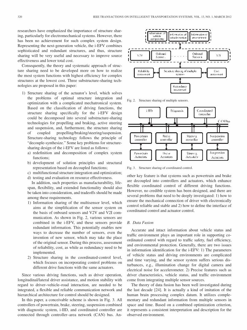
To simplify the controller design and decrease system failure,a decoupled framework is adopted according to the features andfunctionality of the i-EFV while making the most of optimalcomprehensive performance. Basically, as shown in Fig. 5,three issues are proposed and settled by the design of the controlarchitecture.
1) The coordinated controller layer switches or evendetermines coordination through a given weighting co-efficient among different driver modes such as driveroperation, longitudinal/lateral driver assistance, and asmotion stability.
2) The “driver–vehicle–road” multiobjective coordinationlayer seeks to solve the joint optimization problem ofmultiple actuators by consideration of multiple objec-tives of traffic safety, fuel efficiency, and environmental
Fig. 5. Framework of the control system of the i-EFV.
protection. It calculates the main parameters of vehi-cle motion including longitudinal, lateral, and verticaldirections. Moreover, the critical needs for multiobjec-tive optimized control are real-time performance, robust-ness, and stability, and much attention should be paidto it [28]–[30].
3) Dynamic coordination of electromechanically coupledsystem layer emphasizes the following two points:1) nonlinearity of electromechanically coupled compo-nents and 2) functionality overlap and coordinated controlof systems of driving, braking, steering, and suspension,considering the differences of dynamic response andcontrol profit, which determines how much the controllercould achieve (e.g., safety, economy), compared withhow much it costs. The theories of both nonlinear dy-namic control and optimal control should be applied withmore discussion on how to combine these two mecha-nisms and the consequent problems of chattering, real-time performance, and stability.
IV. CASE STUDIES OF THE INTELLIGENT
ENVIRONMENT-FRIENDLY VEHICLE
To establish the platform of a conceptual i-EFV and validateits comprehensive advantages in traffic safety, fuel efficiency,and environmental protection, a prototype of the i-HEV hasbeen designed and implemented. It consists of a sensor system,hybrid electric powertrain, active brakes, and a vehicle controlsystem. It has ACC and can manage the power distributionbetween the engine and motors. Finally, the i-HEV has beenverified by simulations and experiments, and the results duringdriver assistance show comprehensive performance in trafficsafety, fuel efficiency, and environmental protection.
LI et al.: INTELLIGENT ENVIRONMENT-FRIENDLY VEHICLES: CONCEPT AND CASE STUDIES 323
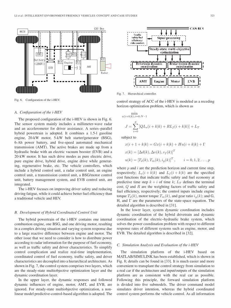
Fig. 6. Configuration of the i-HEV.
A. Configuration of the i-HEV
The proposed configuration of the i-HEV is shown in Fig. 6.The sensor system mainly includes a millimeter-wave radarand an accelerometer for driver assistance. A series–parallelhybrid powertrain is adopted. It combines a 1.5-l gasolineengine, 20-kW motor, 5-kW belt starter/generator (BSG),6-Ah power battery, and five-speed automated mechanicaltransmission (AMT). The active brakes are made up from ahydraulic brake with an electric vacuum booster (EVB) and a20-kW motor. It has such drive modes as pure electric drive,pure engine drive, hybrid drive, engine drive while generat-ing, regenerative brake, etc. The vehicle controllers, whichinclude a hybrid control unit, a radar control unit, an enginecontrol unit, a transmission control unit, a BSG/motor controlunit, battery management system, and EVB control unit, areintegrated.
The i-HEV focuses on improving driver safety and reducingdriving fatigue, while it could achieve better fuel efficiency thana traditional vehicle and HEV.
B. Development of Hybrid Coordinated Control Unit
The hybrid powertrain of the i-HEV contains one internalcombustion engine, one BSG, and one driving motor, resultingin a complex driving situation and varying system response dueto a large reactive difference between engine and motor. Theother issue that we need to consider is how to distribute poweraccording to radar information for the purpose of fuel economy,as well as traffic safety and driver characteristics. To simplifycontrol complication and realize real-time implementation,coordinated control of fuel economy, traffic safety, and drivercharacteristics are decoupled into a hierarchical architecture. Asshown in Fig. 7, the control system comprises two layers, whichare the steady-state multiobjective optimization layer and thedynamic coordination layer.
In the upper layer, the dynamic responses and followeddynamic influences of engine, motor, AMT, and EVB, areignored. For steady-state multiobjective optimization, a non-linear model predictive-control-based algorithm is adopted. The
Fig. 7. Hierarchical controller.
control strategy of ACC of the i-HEV is modeled as a recedinghorizon optimization problem, which is shown as
minu(i+k|k),i=0:N−1
J =p∑
i=0
[QLs(i + k|k) + RLf (i + k|k)] + LT
subject to
x(i + 1 + k|k) = Gx(i + k|k) + Hu(i + k|k) + Γ
x(k) = [Δd(k),Δv(k), vf (k)]T
u(k) = [Td(k), Tm(k), ig(k)]T , i = 0, 1, 2, . . . , p
where p and i are the prediction horizon and current time step,respectively; Ls(i + k|k) and Lf (i + k|k) are the specifiedcost functions that indicate traffic safety and fuel economy atpredictive time step k + i of time k; LT defines the terminalcost; Q and R are the weighting factors of traffic safety andfuel efficiency, respectively; the control inputs include enginetorque Td(k), motor torque Tm(k), and gear ratio ig(k); and G,H, and Γ are the parameters of the state-space equation. Thedetailed algorithm is described in [31].
In the lower layer, system dynamic coordination includesdynamic coordination of the hybrid drivetrain and dynamiccoordination of the electric–hydraulic brake system, whichsolves the power coordination problem with respect to differentresponse rates of different systems such as engine, motor, andEVB. The detailed algorithm is described in [32].
C. Simulation Analysis and Evaluation of the i-HEV
The simulation platform of the i-HEV based onMATLAB/SIMULINK has been established, which is shown inFig. 8; details can be found in [33]. It is much easier and moreconvenient to transplant the control strategy from simulation toa real car if the architecture and input/outputs of the simulationplatform are as consistent with the real car as possible.Following this principle, the forward simulation platformis divided into five submodels. The driver command modelsimulates driver intention, whereas the hybrid coordinatedcontrol system performs the vehicle control. As all information

324 IEEE TRANSACTIONS ON INTELLIGENT TRANSPORTATION SYSTEMS, VOL. 13, NO. 1, MARCH 2012
Fig. 8. Scheme of the forward simulation platform.
is communicated through a CAN bus, the sensor model takescharge of processing and transferring information to thecontrol system. The radar sensor is simulated using kinematicsequations, given the acceleration of the preceding vehicle. Thecomponents and vehicle dynamics model are used to simulatethe response of a real car. In addition, a special observerinterface is utilized to watch the vehicle component states andcontroller command.
Furthermore, to demonstrate the comprehensive performanceof ACC of the i-HEV, the simulation is tested, compared withthree objects: ACC of a conventional vehicle, HEV, and i-HEVusing a proportional–integral–differential (PID) controller.
1) Compared With ACC of Conventional Vehicle: To makean easy comparison, the same engine of the i-HEV is adoptedin a conventional IV without a battery and a motor. The otherparameters are the same as that of the i-HEV. As described inprevious sections, since the i-HEV integrates ITS and hybridpowertrain, when compared with ACC of the IV, ACC of thei-HEV is both more fuel efficient and faster respondent.
To validate the performance of faster response of the i-HEV,a simulation of intense deceleration is implemented, as shownin Fig. 9.
In this simulation, the preceding vehicle decelerates with−2 m/s2. Thus, the following vehicle decelerates at a properdeceleration. ACC of the i-HEV and conventional IV are com-pared under the same brake power command. From Fig. 9(a),although the command of brake power is the same, the fol-lowing velocities are different. More evidence could be foundfrom Fig. 9(b), i.e., the phase of relative velocity versus relativedistance error. Due to the fast response of the motor of thei-HEV, the distance error of the i-HEV is smaller than that ofthe IV, which results in faster tracking and more safety potentialin some emergent situation.
To validate the performance of fuel efficiency of the i-HEV,simulation with the preceding velocity assumed to follow a sinewave from 55 to 75 km/h is implemented, which is shown inFig. 10. It is found that the following vehicle could track thepreceding vehicle fast and smoothly, and the time lag is lessthan 3 s.
Engine fuel consumption with different initial state of charge(SOC) and ΔSOC is shown in Table I. According to the fittingline of ΔSOC versus engine fuel in Fig. 11, the equivalent fuelconsumption of the i-HEV can be determined from the pointwhere ΔSOC is zero [34]. From this figure, it is found that theequivalent fuel consumption is 4.74 l/100 km.
However, with a sole power source, the engine operatingpoints of a conventional IV are limited by various powerdemands. To compare the fuel efficiency, the same followingspeed profile as ACC of the i-HEV is constrained. Conse-
Fig. 9. Simulation results of intense deceleration.
Fig. 10. Simulation results of sinusoidal following.
TABLE IFUEL CONSUMPTION PER 100 km
quently, on the condition of the same propulsion and brakepower command, fuel consumption of conventional IV is simu-lated, and the result is 5.63 l/100 km. This ultimately results ina 15.8% increase of fuel consumption compared with ACC ofthe i-HEV.

LI et al.: INTELLIGENT ENVIRONMENT-FRIENDLY VEHICLES: CONCEPT AND CASE STUDIES 325
Fig. 11. Fitting results of fuel consumption of the i-HEV.
Fig. 12. Simulation results of the real drive cycle.
2) Compared With HEV: The basic idea of ACC of thei-HEV is to combine the traffic safety and ride comfort of ITSswith the fuel efficiency of hybrid electric systems. Furthermore,when comparing with HEVs, due to more flexible power de-termination, the ACC of the i-HEV could achieve better fueleconomy while maintaining reasonable tracking ability.
Two scenarios from real drive are implemented. As shown inFig. 12(a), preceding velocity from experiment is an approxi-mate sinusoidal motion. On the condition of the aforementionedpreceding velocity as input, simulations of ACC of the i-HEVare implemented, and the simulated following velocity of the
TABLE IIFUEL CONSUMPTION OF THE REAL DRIVE CYCLE
Fig. 13. ISUZU ACC test cycle.
i-HEV is represented by the thick solid line. The dashed linerepresents the velocity of the HEV, which is from experimentalresults by the real driver. It is found that both the velocity of thei-HEV and HEV could track the preceding vehicle. However,the i-HEV is smoother and has low overshoot. Similarly, an-other cruise scenario is also simulated, as shown in Fig. 12(b).
To compare the fuel consumption of the HEV and i-HEV, thespeed profile of the HEV is converted into vehicle propulsionpower through the same vehicle parameters as those of thei-HEV, and fuel consumption is calculated based on a rule-based energy management strategy [5] and the same hybridpowertrain model as that of the i-HEV. Consequently, an equiv-alent fuel consumption taking SOC into account is listed inTable II. It is found that, in real cycle 1, the fuel economy of theHEV with driver is 6.04 l/100 km, whereas ACC of the i-HEVis 5.2 l/100 km, which results in 13.9% improvement. Duringreal cycle 2, an improvement of 6.52% on the fuel efficiency ofthe i-HEV is achieved.
3) Compared With ACC of the i-HEV Using PID Controller:Since ACC of the i-HEV integrates radar sensor and hybridelectric powertrain, it provides more optimization potential andflexibility to achieve both fuel efficiency and traffic safety dur-ing the following process. In the following, the fuel efficiencyof ACC of the i-HEV by an optimal coordinated controller andPID-based controller is compared.
The ISUZU ACC test cycle is adopted here and shown inFig. 13. To reflect the tracking capability, the index is definedby both speed error and distance error as [28]
S =1N
p∑i=1
(∣∣∣∣Δd(i)KDV
∣∣∣∣ + |Δv(i)|)
where KDV is the weighting coefficient, which is selected as10. The total equivalent fuel consumption and tracking abilityindex S are both listed in Table III. It is found that ACC ofthe i-HEV with coordinated control, considering both safety

326 IEEE TRANSACTIONS ON INTELLIGENT TRANSPORTATION SYSTEMS, VOL. 13, NO. 1, MARCH 2012
TABLE IIIFUEL CONSUMPTION AND TRACKING ABILITY OF THE ISUZU CYCLE
Fig. 14. Besturn i-HEV.
and fuel economy, could achieve 4.84% fuel improvement thanPID-based ACC of the HEV, with only 3.6% compromise oftracking ability.
D. Experimental Verification of the i-HEV
After the simulation analysis, we have designed the i-HEV(as shown in Fig. 14). Next, the rapid control prototype isdeveloped based on MICROAUTOBOX; finally, experimentswith rule-based strategy are carried out. The hierarchical con-trol framework is adopted. The problem of ACC of the i-HEVis decoupled into drive power determination and rule-basedenergy management; a detailed algorithm is described in [32].
During the adaptive cruise mode, the preceding velocity is asine wave from 20 to 35 km/h, and the initial following velocityis 17 km/h. The experiment results are shown in Figs. 15and 16.
The results show that, in the initial stage of sinusoidal,following as a transition phase, the i-HEV follows with a delayand a larger error. In the first sine cycle, both the engine andmotor are propelling due to the large demanded acceleration.As error decreases, the torque demand is reduced, and enginedriving with BSG charging mode is achieved. Then, with powerdemand further reduced, the i-HEV works in pure electricdriving mode. With a sudden slowdown of the preceding vehi-cle, the following vehicle then decelerates with both motor andEVB braking, maintaining a desired relative velocity and safetydistance. Subsequently, since the preceding and following ve-hicles enter the stable phase, an excellent sinusoidal followingis achieved, during which both velocity and distance errorsstay small, and the i-HEV driving mode seamlessly switchesbetween pure electric driving, engine driving and motor gener-ating, parallel driving, and braking energy regenerating modes.
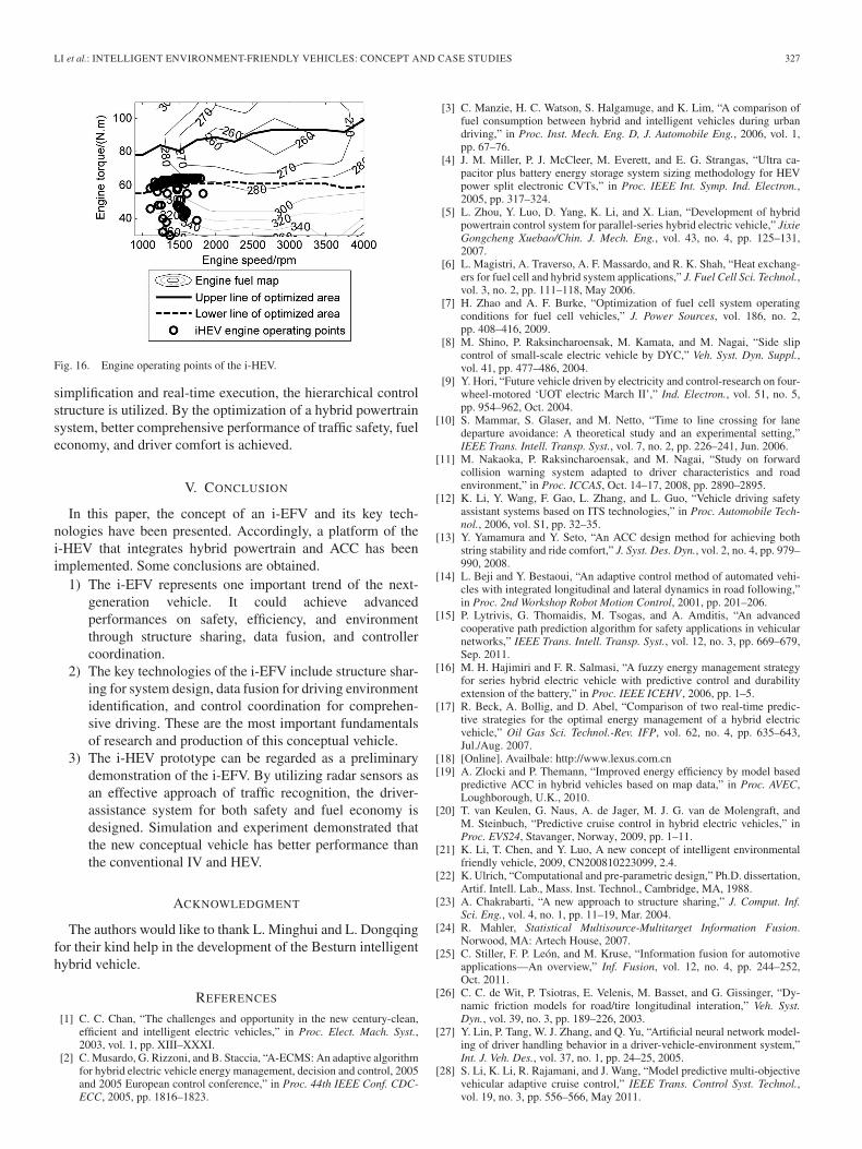
As shown in Fig. 16, the operating points of the enginewith a ◦ are obtained, and the two solid and dashed lines arethe engine’s economic range defined by a rule-based energymanagement strategy. The results demonstrate that most op-erating points of the engine are within the engine’s economicrange according to an optimization among the engine, BSG,and driving motor. This can effectively improve vehicle fueleconomy. The few engine working points below the economicrange are dynamic points when the engine is decelerating
Fig. 15. Experimental result of adaptive cruise mode.
or accelerating, and they may not have much effect on fuelconsumption.
The i-HEV is a new conceptual vehicle as a first-step pro-totype of the i-EFV. It is propelled by a hybrid propulsionsystem. To realize assisted driving, the vehicle has an activeelectric–hydraulic brake equipped with both EVB and motor, aswell as radar to detect the preceding velocity and distance. For
LI et al.: INTELLIGENT ENVIRONMENT-FRIENDLY VEHICLES: CONCEPT AND CASE STUDIES 327
Fig. 16. Engine operating points of the i-HEV.
simplification and real-time execution, the hierarchical controlstructure is utilized. By the optimization of a hybrid powertrainsystem, better comprehensive performance of traffic safety, fueleconomy, and driver comfort is achieved.
V. CONCLUSION
In this paper, the concept of an i-EFV and its key tech-nologies have been presented. Accordingly, a platform of thei-HEV that integrates hybrid powertrain and ACC has beenimplemented. Some conclusions are obtained.
1) The i-EFV represents one important trend of the next-generation vehicle. It could achieve advancedperformances on safety, efficiency, and environmentthrough structure sharing, data fusion, and controllercoordination.
2) The key technologies of the i-EFV include structure shar-ing for system design, data fusion for driving environmentidentification, and control coordination for comprehen-sive driving. These are the most important fundamentalsof research and production of this conceptual vehicle.
3) The i-HEV prototype can be regarded as a preliminarydemonstration of the i-EFV. By utilizing radar sensors asan effective approach of traffic recognition, the driver-assistance system for both safety and fuel economy isdesigned. Simulation and experiment demonstrated thatthe new conceptual vehicle has better performance thanthe conventional IV and HEV.
ACKNOWLEDGMENT
The authors would like to thank L. Minghui and L. Dongqingfor their kind help in the development of the Besturn intelligenthybrid vehicle.
REFERENCES
[1] C. C. Chan, “The challenges and opportunity in the new century-clean,efficient and intelligent electric vehicles,” in Proc. Elect. Mach. Syst.,2003, vol. 1, pp. XIII–XXXI.
[2] C. Musardo, G. Rizzoni, and B. Staccia, “A-ECMS: An adaptive algorithmfor hybrid electric vehicle energy management, decision and control, 2005and 2005 European control conference,” in Proc. 44th IEEE Conf. CDC-ECC, 2005, pp. 1816–1823.
[3] C. Manzie, H. C. Watson, S. Halgamuge, and K. Lim, “A comparison offuel consumption between hybrid and intelligent vehicles during urbandriving,” in Proc. Inst. Mech. Eng. D, J. Automobile Eng., 2006, vol. 1,pp. 67–76.
[4] J. M. Miller, P. J. McCleer, M. Everett, and E. G. Strangas, “Ultra ca-pacitor plus battery energy storage system sizing methodology for HEVpower split electronic CVTs,” in Proc. IEEE Int. Symp. Ind. Electron.,2005, pp. 317–324.
[5] L. Zhou, Y. Luo, D. Yang, K. Li, and X. Lian, “Development of hybridpowertrain control system for parallel-series hybrid electric vehicle,” JixieGongcheng Xuebao/Chin. J. Mech. Eng., vol. 43, no. 4, pp. 125–131,2007.
[6] L. Magistri, A. Traverso, A. F. Massardo, and R. K. Shah, “Heat exchang-ers for fuel cell and hybrid system applications,” J. Fuel Cell Sci. Technol.,vol. 3, no. 2, pp. 111–118, May 2006.
[7] H. Zhao and A. F. Burke, “Optimization of fuel cell system operatingconditions for fuel cell vehicles,” J. Power Sources, vol. 186, no. 2,pp. 408–416, 2009.
[8] M. Shino, P. Raksincharoensak, M. Kamata, and M. Nagai, “Side slipcontrol of small-scale electric vehicle by DYC,” Veh. Syst. Dyn. Suppl.,vol. 41, pp. 477–486, 2004.
[9] Y. Hori, “Future vehicle driven by electricity and control-research on four-wheel-motored ‘UOT electric March II’,” Ind. Electron., vol. 51, no. 5,pp. 954–962, Oct. 2004.
[10] S. Mammar, S. Glaser, and M. Netto, “Time to line crossing for lanedeparture avoidance: A theoretical study and an experimental setting,”IEEE Trans. Intell. Transp. Syst., vol. 7, no. 2, pp. 226–241, Jun. 2006.
[11] M. Nakaoka, P. Raksincharoensak, and M. Nagai, “Study on forwardcollision warning system adapted to driver characteristics and roadenvironment,” in Proc. ICCAS, Oct. 14–17, 2008, pp. 2890–2895.
[12] K. Li, Y. Wang, F. Gao, L. Zhang, and L. Guo, “Vehicle driving safetyassistant systems based on ITS technologies,” in Proc. Automobile Tech-nol., 2006, vol. S1, pp. 32–35.
[13] Y. Yamamura and Y. Seto, “An ACC design method for achieving bothstring stability and ride comfort,” J. Syst. Des. Dyn., vol. 2, no. 4, pp. 979–990, 2008.
[14] L. Beji and Y. Bestaoui, “An adaptive control method of automated vehi-cles with integrated longitudinal and lateral dynamics in road following,”in Proc. 2nd Workshop Robot Motion Control, 2001, pp. 201–206.
[15] P. Lytrivis, G. Thomaidis, M. Tsogas, and A. Amditis, “An advancedcooperative path prediction algorithm for safety applications in vehicularnetworks,” IEEE Trans. Intell. Transp. Syst., vol. 12, no. 3, pp. 669–679,Sep. 2011.
[16] M. H. Hajimiri and F. R. Salmasi, “A fuzzy energy management strategyfor series hybrid electric vehicle with predictive control and durabilityextension of the battery,” in Proc. IEEE ICEHV , 2006, pp. 1–5.
[17] R. Beck, A. Bollig, and D. Abel, “Comparison of two real-time predic-tive strategies for the optimal energy management of a hybrid electricvehicle,” Oil Gas Sci. Technol.-Rev. IFP, vol. 62, no. 4, pp. 635–643,Jul./Aug. 2007.
[18] [Online]. Availbale: http://www.lexus.com.cn[19] A. Zlocki and P. Themann, “Improved energy efficiency by model based
predictive ACC in hybrid vehicles based on map data,” in Proc. AVEC,Loughborough, U.K., 2010.
[20] T. van Keulen, G. Naus, A. de Jager, M. J. G. van de Molengraft, andM. Steinbuch, “Predictive cruise control in hybrid electric vehicles,” inProc. EVS24, Stavanger, Norway, 2009, pp. 1–11.
[21] K. Li, T. Chen, and Y. Luo, A new concept of intelligent environmentalfriendly vehicle, 2009, CN200810223099, 2.4.
[22] K. Ulrich, “Computational and pre-parametric design,” Ph.D. dissertation,Artif. Intell. Lab., Mass. Inst. Technol., Cambridge, MA, 1988.
[23] A. Chakrabarti, “A new approach to structure sharing,” J. Comput. Inf.Sci. Eng., vol. 4, no. 1, pp. 11–19, Mar. 2004.
[24] R. Mahler, Statistical Multisource-Multitarget Information Fusion.Norwood, MA: Artech House, 2007.
[25] C. Stiller, F. P. León, and M. Kruse, “Information fusion for automotiveapplications—An overview,” Inf. Fusion, vol. 12, no. 4, pp. 244–252,Oct. 2011.
[26] C. C. de Wit, P. Tsiotras, E. Velenis, M. Basset, and G. Gissinger, “Dy-namic friction models for road/tire longitudinal interation,” Veh. Syst.Dyn., vol. 39, no. 3, pp. 189–226, 2003.
[27] Y. Lin, P. Tang, W. J. Zhang, and Q. Yu, “Artificial neural network model-ing of driver handling behavior in a driver-vehicle-environment system,”Int. J. Veh. Des., vol. 37, no. 1, pp. 24–25, 2005.
[28] S. Li, K. Li, R. Rajamani, and J. Wang, “Model predictive multi-objectivevehicular adaptive cruise control,” IEEE Trans. Control Syst. Technol.,vol. 19, no. 3, pp. 556–566, May 2011.

328 IEEE TRANSACTIONS ON INTELLIGENT TRANSPORTATION SYSTEMS, VOL. 13, NO. 1, MARCH 2012
[29] E. Hellström, M. Ivarsson, J. Åslunda, and L. Nielsen, “Look-ahead con-trol for heavy trucks to minimize trip time and fuel consumption,” ControlEng. Pract., vol. 17, no. 2, pp. 245–254, Feb. 2008.
[30] J. Chunyu, Z. Qu, E. Pollak, and M. Falash, “A new multi-objective con-trol design for autonomous vehicles,” Optimization Cooperative ControlStrategies, vol. 381, Lecture Notes in Control and Information Sciences,pp. 81–102, 2009.
[31] T. Chen, Y. Luo, and K. Li, “Multi-objective adaptive cruise control basedon nonlinear model predictive algorithm,” in Proc. IEEE Int. Conf. Veh.Electron. Saf., Beijing, China, 2011, pp. 274–279.
[32] Y. Luo, T. Chen, G. Zhou, and K. Li, “The hierarchy control systemof intelligent hybrid electric vehicle,” in Proc. EVS, Stavanger, Norway,2009.
[33] T. Chen, Y. Luo, and K. Li, “Forward simulation platform of drivingperformance on intelligent hybrid electric vehicle,” in Proc. Int. Conf.Elect. Control Eng., Wuhan, China, 2010.
[34] Recommended Practice for Measuring the Exhaust Emissions and FuelEconomy of Hybrid-Electric Vehicles, Including Plug-in Hybrid Vehicles,Soc. Automotive Eng., SAE J1711, Jun. 2010.
Keqiang Li received the B.Tech. degree fromTsinghua University, Tsinghua, China, in 1985 andM.S. and Ph.D. degrees from Chongqing University,Chongqing, China, in 1988 and 1995, respectively.
He is currently a Professor with the Departmentof Automotive Engineering, Tsinghua University. Heserved on the Editorial Boards of the InternationalJournal of ITS Research and the International Jour-nal of Vehicle Autonomous Systems. He has authoredmore than 90 papers. He is the holder of 12 patentsin China and Japan. His research interests include
vehicle dynamics and control for driver-assistance systems and hybrid electricalvehicles.
Dr. Li has served as a Senior Member of the Society of Automotive Engineersof China. He was the recipient of the “Changjiang Scholar Program Professor”title and several other awards from public agencies and academic institutions inChina.
Tao Chen received the B.Tech. degree in 2007 fromTsinghua University, Tsinghua, China, where he iscurrently working toward the Ph.D. degree with theDepartment of Automotive Engineering.
His research interests include hybrid electric vehi-cles, driver-assistance systems, and a new conceptualintelligent environment-friendly vehicle.
Yugong Luo received the B.Tech. and M.S. degreesfrom Chongqing University, Chongqing, China, in1996 and 1999, respectively, and the Ph.D. degreefrom Tsinghua University, Tsinghua, China, in 2003.
He is currently an Associate Professor with theDepartment of Automotive Engineering, TsinghuaUniversity. He has authored more than 30 journalpapers. He is the co-holder of 15 patent applications.His research interests include vehicle and electricvehicle dynamics and control and vehicle noise,vibration, and harshness analysis and control.
Dr. Luo has been involved with over ten sponsored projects and has receivedtwo awards, including the “The 1st class prize of the Chinese AutomotiveIndustry S&T Progress Award” and “The 2nd class prize of the ministry ofeducation S&T Progress Award.”
Jianqiang Wang received the B.Tech., M.S., andPh.D. degrees from Jilin University of Technology,Jilin, China, in 1994, 1997, and 2002, respectively.
He is currently an Associate Professor with theDepartment of Automotive Engineering, TsinghuaUniversity, Tsinghua, China. He has authored morethan 40 journal papers. He is the co-holder of20 patent applications. His research interests includeintelligent vehicles, driving-assistance systems, anddriver behavior.
Dr. Wang has been involved with over ten spon-sored projects. He was the recipient of six awards, including the “Jilin ProvinceS&T Progress Award” and the “Chinese Automotive Industry S&T ProgressAward.”