Embed Size (px)
Citation preview
INTELLIGENT CONTROL OF DC MOTOR
By
AHMAD IQBAL FAHMI BIN AHMAD KHALIL
FINAL PROJECT REPORT
Submitted to the Department of Electrical & Electronic Engineering
in Partial Fulfillment of the Requirements
for the Degree
Bachelor of Engineering (Hons)
(Electrical & Electronic Engineering)
Universiti Teknologi PETRONAS
Bandar Seri Iskandar
31750 Tronoh
Perak Darul Ridzuan
Copyright 2012
by
Ahmad Iqbal Fahmi Bin Ahmad Khalil, 2012
ii
CERTIFICATION OF APPROVAL
INTELLIGENT CONTROL OF DC MOTOR
by
Ahmad Iqbal Fahmi Bin Ahmad Khalil
A project dissertation submitted to the
Department of Electrical & Electronic Engineering
Universiti Teknologi PETRONAS
in partial fulfilment of the requirement for the
Bachelor of Engineering (Hons)
(Electrical & Electronic Engineering)
Approved:
__________________________
Ir. Dr. Nursyarizal Bin Mohd Nor
Project Supervisor
UNIVERSITI TEKNOLOGI PETRONAS
TRONOH, PERAK
May 2012

iii
CERTIFICATION OF ORIGINALITY
This is to certify that I am responsible for the work submitted in this project, that the
original work is my own except as specified in the references and
acknowledgements, and that the original work contained herein have not been
undertaken or done by unspecified sources or persons.
_________________________________________
AHMAD IQBAL FAHMI BIN AHMAD KHALIL

iv
ABSTRACT
DC Motor still plays a very important instrument in industrial field though many new
designs have been develop. The current way of controlling DC Motor is by using PI
feedback controller in order to achieve the set point. PI controller has been selected
as the result of it advantages compare with the other types. However PI controller
also contain a lot of disadvantages thus which proposed the author to proposal a new
intelligent type of DC Motor controller which use Fuzzy Logic algorithm and called
Fuzzy Logic Controller (FLC). Due to this thesis, Fuzzy Logic Controller has been
design and fabricate. This new controller is using microcontroller, PIC 16F877A as
the main device to do the decision making and been programmed using C language.
The test then been conducted on PI Controller and Fuzzy Logic Controller to
compare the efficiency in controlling the DC Motor. Based on the result, Fuzzy
Logic Controller gives better performance compare with PI Controller. For the
further studies other intelligent approach was been suggested instead of using Fuzzy
Logic algorithm.

v
ACKNOWLEDGEMENTS
This project work was supported by Final Year Project Programme and was
carried out from January 2012 until September 2012 under supervision of Associate
Professor Dr Nirod Chandra Sahoo from Electrical & Electronics Department of
Universiti Teknologi PETRONAS and Ir. Dr. Nursyarizal Bin Mohd Nor from
Electrical & Electronics Department of Universiti Teknologi PETRONAS. I would
like to express my gratitude towards their guidance and advice throughout the
programme.
I would like also to express my appreciation towards my parent Mr Ahmad
Khalil Bin Mohd Fahmi and Ms Salmah Binti Ismail, my siblings, my friends and
my fellow colleague for their encouragement and support. To conclude, I would like
to thank everyone who involve directly or indirectly with this project. Thank you.
vi
TABLE OF CONTENTS
CERTIFICATION OF APPROVAL . . . . . ii
CERTIFICATION OF ORIGINALITY . . . . . iii
ABSTRACT . . . . . . . . iv
ACKNOWLEDGEMENTS . . . . . . v
TABLE OF CONTENT . . . . . . . vi
LIST OF FIGURE . . . . . . . viii
LIST OF TABLES . . . . . . . ix
LIST OF ABBREVIATIONS . . . . . . x
CHAPTER 1: INTRODUCTION . . . . . 1
1.1. Background of Study . . . . 1
1.2. Problem Statement and Identification . . 2
1.3. Significant and Feasibility of the Project. . 2
1.4. Objective and Scope of Study. . . 3
CHAPTER 2: LITERATURE REVIEW . . . . 5
2.1. Controller. . . . . . 5
2.2. Converter. . . . . . 7
2.3. DC Motor. . . . . . 9
2.4. Four Quadrant Operations. . . . 13
CHAPTER 3: METHODOLOGY . . . . . 17
3.1. Research Methodology . .. . 17
vii
3.2 Project Activities. . . . . 18
3.3 Program Sequence. . . . . 19
3.2 Hardware Layout. . . . . 20
3.5 Gantt Chart and Milestone for FYP1 . . 22
3.5 Gantt Chart and Milestone for FYP2 . . 23
3.4 Tools Use . . . . . 24
CHAPTER 4: RESULT AND DISCUSSION . . . 25
4.1 Extracting Data from Instruments . . 25
4.2 Simulation Diagram on PI feedback controller. 25
4.3 Generated Output . . . . 26
4.4 Discussion on Problem with PI Controller. . 27
4.5 Fabrication Results and Discussion . 28
4.6 Prototype. . . . 31
4.7 Prototype Limitation . . . . 33
4.8 Problems and Solutions . . . 33
CHAPTER 5: CONCLUSION . . . . . 34
5.1 Relevancy to the Objectives . . . 34
5.2 Suggested Future Work for Expansion . 34
REFERENCES . . . . . . . . 35
APPENDIXES . . . . . . . . I
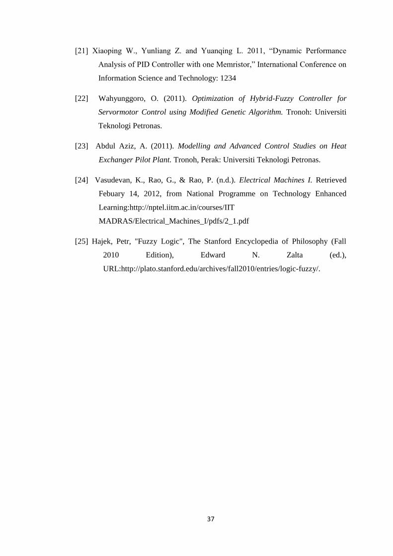
Appendix A: Program Flow Chart . . . I
Appendix B: Program Source Code. . . VI
Appendix C: Program Header Code. . . XI
viii
LIST OF FIGURES
Figure 2.1. 1: Conventional PID Controller . . . . . 6
Figure 2.1. 2: Fuzzy Logic Controller Diagram . . . . 7
Figure 2.2.2 1: Full-bridge Converter . . . . . 9
Figure 2.3. 1: Shunt DC Motor Equivalent Circuit . . . . 11
Figure 2.3. 2: Series DC Motor Equivalent Circuit . . . . 12
Figure 2.4. 1: Forward Drive Characteristic Graph vs. Speed . . 14
Figure 2.4. 2Quadrant Operation Modes Speed vs. Torque . . . 15
Figure 2.4. 3: Quadrant Operation Modes Armature Voltage vs Armature Current 16
Figure 3. 1: Research Methodology . . . . . . 17
Figure 3.3.1: Program Flow Chart Part A . . . . . 20
Figure 3.3.2: Program Flow Chart Part B . . . . . 21
Figure 3.3.3: Program Flow Chart Part C . . . . . 22
Figure 3.3.4: Program Flow Chart Part D . . . . . 23
Figure 3.3.5: Program Flow Chart Part E . . . . . 24
Figure 3.4: Hardware Layout. . . . . . . 20
Figure 4.2: PI Feedback Controller Diagram. . . . . 25
Figure 4.3: Motor Speed Output. . . . . . 26
Figure 4.4.1: Overshoot. . . . . . . 27
Figure 4.4.2: Rise Time. . . . . . . 28
Figure 4.5.1: Conventional PI Controller without Load . . . 28
Figure 4.5.2: Fuzzy Logic Controller without Load . . . . 29
Figure 4.5.3: Conventional PI Controller with Load . . . . 29
Figure 4.5.4: Fuzzy Logic Controller with Load . . . . 30
Figure 4.6.1: Prototype Picture . . . . . . 32
Figure 4.6.2: Prototype External Connection . . . . . 32

ix
LIST OF TABLES
Table 3.3: Gant Chart and Milestone for FYP 1. . . . . 22
Table 3.4: Gant Chart and Milestone for FYP 2. . . . . 23
Table 4.5.5a: PI Controller and Fuzzy Logic Controller without Load . 31
Table 4.5.5b: PI Controller and Fuzzy Logic Controller with Load . . 31
Table 4.6: Prototype Specification . . . . . . 33

x
LIST OF ABBREVIATIONS
Influence field flux
ω Speed in Radian per Second
DC Direct Current
DC Motor Direct Current Motor
EMF Electro Magnetic Field
FLC Fuzzy Logic Controller
Ia Armature Current
Iamax Maximum Armature Voltage
Field current
Field constant
Kv Back EMF Constant
LCD Liquid Crystal Display
PI Proportional Integral
PI Controller Proportional Integral Controller
PID Proportional Integral Derivative
PIC Controller Proportional Integral Derivative Controller
PWM Pulse Width Modulation
Ra Armature Resistant
Field Resistant
The time taken for the switch to be on one cycle
tr Rise Time
ts Settling time
Time taken for a cycle
Va Armature Voltage
Vd Input Voltage
Vo Output Voltag
1
CHAPTER 1: INTRODUCTION
1.1. Background of Study
DC Motor has played a very major part in present days. Although many new
motor’s design has been created, none of the designs created have being able to
really replace DC Motor as a motor. DC Motor characteristic of able turning on clock
direction and anti-clock direction made DC Motor special compare with the other
motor. This ability made DC Motor still being used in much equipment such as
elevator, crane, and electric cars. In additional to that it is important to control DC
Motor in order to able DC Motor to function at maximum optimization. Besides that,
the controller also needs to take care of the safety and the working specification in
order to able the DC Motor to function at maximum period.
At the present technology, the common type of controller that being use is
Proportional Integral Derivative (PID) feedback controller which has been used few
years backward [21]. Proportional Integral Derivative (PID) type of controller
becomes popular due to it characteristic that makes it simple, robust and practical in
real device, thus make it become conventional kind of controller [23]. However,
Proportional Integral Derivative (PID) is far from prefect and consists of
disadvantages that make it replaceable. A new way of controlling DC Motor will be
proposed which use Fuzzy Logic Algorithm to create Fuzzy Logic Controller (FLC).
One of major concern in using Proportional Integral Derivative (PID)
controller is the complexity to use it in bigger environment which require higher
capability controller. More than that, Proportional Integral Derivative (PID)
controller is harder to be tuned and sometimes required more time, thus produce loss
[21]. Due to this defect, many major researches have been done in order to counter
the problem thus achieve better result. This development then bring artificial
intelligent technology such as Neural Network Controller (ANN) [2], Model
Predictive Controller (MPC) [3], Genetic Algorithm (GA) [22] and Fuzzy Logic
Controller (FLC) [23].
2
Compare with the conventional controller, Fuzzy Logic Controller (FLC) is
easier to be used as it is closer to human way of decision making. This is because,
Fuzzy Logic Controller (FLC) use approximation instead of absolute decision.
Besides that, Fuzzy Logic Controller (FLC) is able to be used with complex system
by using Fuzzy Logic Controller’s quantitative technique. Additional to that,
experiment has already proved that Fuzzy Logic Controller (FLC) give better result
than conventional controller in many fields. Fuzzy Logic Algorithm has been taken
as in involvement between mathematical machine’s ways of controlling into human’s
approximation decision making [16].
1.2. Problem Statement and Identification
DC Motor is currently widely used in industry due to DC Motor specific
advantages. Due to that, it is important for the controller to function properly in order
to gain maximum output without sacrificing DC Motor life span. Based on the
current technology, the conventional controller for DC Motor is using Proportional
Integrated (PI) Feedback controller [23]. However, due to it characteristics,
Proportional Integrated (PI) Feedback controller gives few problem in controlling the
system and DC Motor specifically.
First and for most, DC Motor have the disadvantage of giving nonlinearity
effect for example dead zone, saturation, and friction thus disturb the performance of
the convention controller. Additional to that, DC Motor characteristics is not easy to
be extract thus makes the tuning process become hard [1] [18]. On the other hand,
without properly tune, the controller would not be able to generate maximum output.
Normal Proportional Integral (PI) feedback controller took time in order to settle
where else Proportional Integral Derivative (PID) feedback controller tend to give
overshoot [9].
Due to this defect, it is important to generate a new way of controlling the
system without neglecting DC Motor requirement need to be generated.
1.3. Significant and Feasibility of the Project
Fuzzy Logic Controller is one of intelligent types of controller. Fuzzy Logic
Controller (FLC) use approximation technique in order to generate the result [6].
Compare with conventional controller, Fuzzy Logic Controller (FLC) do not require
3
specific model in order to form it controller setting. By this way, Fuzzy Logic
Controller (FLC) will be able to reduce the complication of a complicated system.
Besides that, according to Shaker, Fuzzy Logic Controller (FLC) has the ability to
reduce the effect of nonlinearity in DC Motor when nonlinear defuzzification is
being used [5]. By this way, the system will be smoother thus gain better gain in the
output.
Similarly, by using Fuzzy Logic Controller (FLC) the system will have faster
dynamic response but without overshoot. By this way, the system will be more
practical and stable [1] [6] [18-19]. The logic works by scaling the output based on
the input thus will be user friendly towards the operator as it is similar to how their
work was done [23].
The overall project has been divided into two part which is the simulation
part and real fabricating part. For Final Year Project One (FYP1), the project will be
focus on simulation. Simulation is important in order to experiment the data and
design in order to the functioned system without theoretical problem. The project
then continue with fabrication and prototype analysis on Final Year Project Two
(FYP2)
1.4. Objective and Scope of Study
The main objective of this project is to develop a control system a control
system on DC Motor by using Fuzzy Logic Controller (FLC) on microcontroller,
PIC16F877A. The improvement in this system is being conducted by substituting the
present conventional control system that used Proportional Integral Derivative (PID)
Feedback Controller with Fuzzy Logic Controller (FLC).
Besides that, the new system is necessary to be able to obey all the safety
rules and procedures. Every system especially DC Motor have their own safety
requirement. This rules and procedure is very important to be followed in order to
ensure the safety of the devices and the users.
Last but not least, the objective in this project is also to observe and supply
additional improvement that can be conduct and being improvise for future research.
Continuity is important in order to ensure humans advancement. By this way the
4
participation of Fuzzy Logic on control system and other field will keep continue
growing and improve.
The study begins by understanding and simulating conventional control of
DC Motor. The study was continued by doing research on Fuzzy Logic Controller
(FLC) in control system and specifically for DC Motor. By using the research data,
the Fuzzy Logic Controller (FLC) for DC Motor has being designed and being
simulated in MATLAB. The result then was being observed and analysed in order to
generate the best outcome. At the end, the design was t fabricated and was ensure it
generate the simulated outcome. The duration of the project is two semesters which
divided into FYP 1 and FYP 2.
5
CHAPTER 2: LITERATURE REVIEW
2.1 Controller
As for human’s body being control by brain, it is important for today’s machine
to have a great control system. The controller makes sure that the machine operates
by following the correct procedures, obeying all the safety measurement and be able
to operate at maximum capacity. Based on this project, the controller should be able
to control the speed of the motor, and must ensure that the armature current, Ia, is
below the maximum armature current, Iamax.
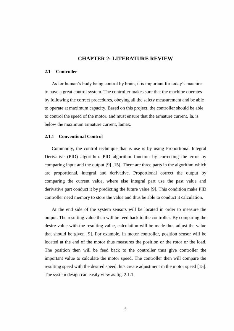
2.1.1 Conventional Control
Commonly, the control technique that is use is by using Proportional Integral
Derivative (PID) algorithm. PID algorithm function by correcting the error by
comparing input and the output [9] [15]. There are three parts in the algorithm which
are proportional, integral and derivative. Proportional correct the output by
comparing the current value, where else integral part use the past value and
derivative part conduct it by predicting the future value [9]. This condition make PID
controller need memory to store the value and thus be able to conduct it calculation.
At the end side of the system sensors will be located in order to measure the
output. The resulting value then will be feed back to the controller. By comparing the
desire value with the resulting value, calculation will be made thus adjust the value
that should be given [9]. For example, in motor controller, position sensor will be
located at the end of the motor thus measures the position or the rotor or the load.
The position then will be feed back to the controller thus give controller the
important value to calculate the motor speed. The controller then will compare the
resulting speed with the desired speed thus create adjustment in the motor speed [15].
The system design can easily view as fig. 2.1.1.
6
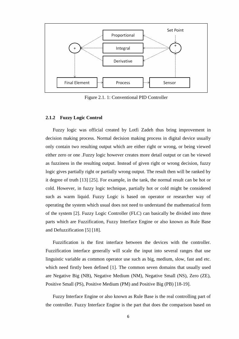
2.1.2 Fuzzy Logic Control
Fuzzy logic was official created by Lotfi Zadeh thus bring improvement in
decision making process. Normal decision making process in digital device usually
only contain two resulting output which are either right or wrong, or being viewed
either zero or one .Fuzzy logic however creates more detail output or can be viewed
as fuzziness in the resulting output. Instead of given right or wrong decision, fuzzy
logic gives partially right or partially wrong output. The result then will be ranked by
it degree of truth [13] [25]. For example, in the tank, the normal result can be hot or
cold. However, in fuzzy logic technique, partially hot or cold might be considered
such as warm liquid. Fuzzy Logic is based on operator or researcher way of
operating the system which usual does not need to understand the mathematical form
of the system [2]. Fuzzy Logic Controller (FLC) can basically be divided into three
parts which are Fuzzification, Fuzzy Interface Engine or also known as Rule Base
and Defuzzification [5] [18].
Fuzzification is the first interface between the devices with the controller.
Fuzzification interface generally will scale the input into several ranges that use
linguistic variable as common operator use such as big, medium, slow, fast and etc.
which need firstly been defined [1]. The common seven domains that usually used
are Negative Big (NB), Negative Medium (NM), Negative Small (NS), Zero (ZE),
Positive Small (PS), Positive Medium (PM) and Positive Big (PB) [18-19].
Fuzzy Interface Engine or also known as Rule Base is the real controlling part of
the controller. Fuzzy Interface Engine is the part that does the comparison based on
Figure 2.1. 1: Conventional PID Controller
7
the input to generate output. The general way to view the comparison is to generate
the output based on IF condition. As an example, “If x is Negative Zero, Then y
should be 1”, [1] [19].
Last but not least is the Defuzzification Interface. Defuzzication Interface played
important role in translating Fuzzy Logic Controller (FLC) into non-Fuzzy control
action [2] [4-5] [19]. Defuzzification is important in order to ensure that the
controlling process run smoothly
2.2 Converter
In order to control to control the speed of the motor it is necessary to have the
average given voltage to be controlled. By using converter, Pulse Width Modulation
(PWM) output will be generate thus will affected the speed. Converter will react as
the interface between the controller and the motor. Generally there are two input type
single phase converter which differentiate by the type of input which are DC input or
AC input [15]. For this study, only DC input will be introduce as it will be used
Figure 2.1. 2: Fuzzy Logic Controller Diagram
8
instead of AC input. Besides that, converter also being classified based on their
characteristic and quadrant functionality. However, in this study only one of the
types which are full-converter is going to be discussed.
2.2.1 DC-DC Mode Converter
Generally DC-DC converter functions by switching normal constant voltage into
high speed alternating voltage. By doing so, the average given voltage will be lower
than it should be thus able to control the speed of the motor [8]. The common
switches that usually use are Metal-Oxide Semiconductor Field Effect Transistor
(MOSFETs), Insulated Gate Bipolar Transistor (IGBTs) and Silicon Controlled
Rectifier (SCR) [14]. According to Mohan, the average voltage for PWM signal’s
output is manipulate by the duration that the switch is on during it cycle or know as
duty ratio [11]. The statement can be clearly visualized by equation (1).
(1)
Where is the output voltage, is the input voltage, the time taken for the
switch to be on one cycle and time taken for a cycle.
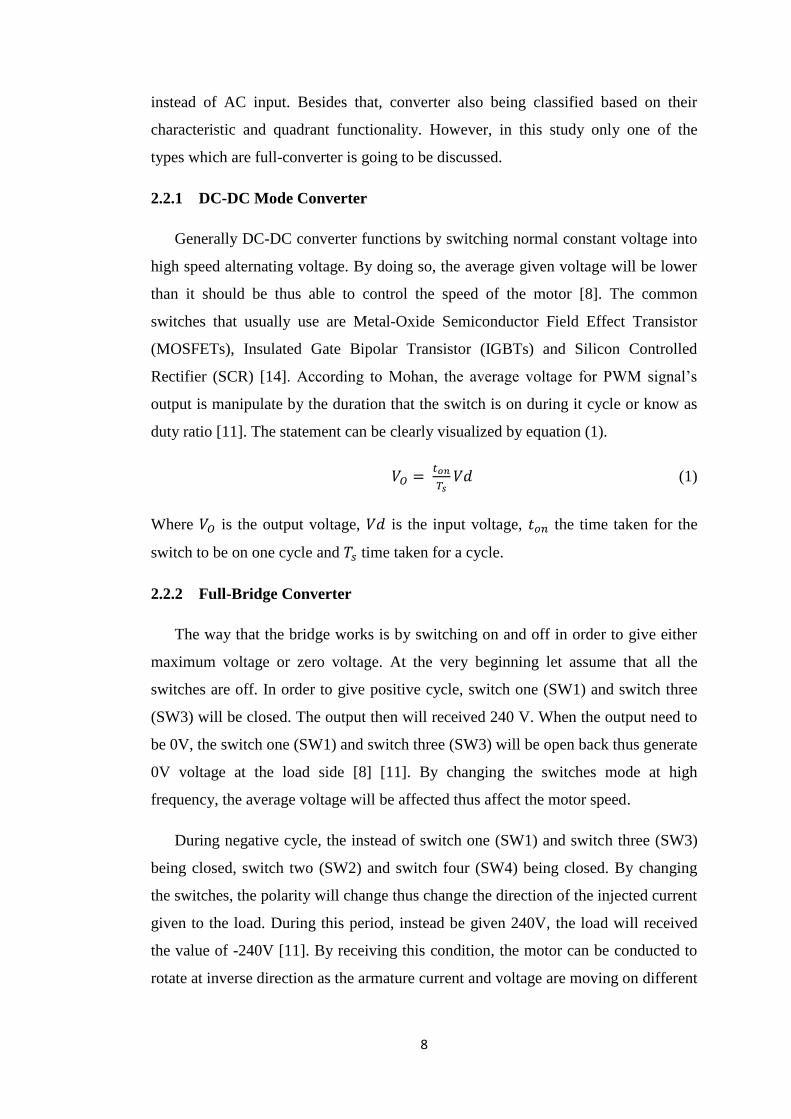
2.2.2 Full-Bridge Converter
The way that the bridge works is by switching on and off in order to give either
maximum voltage or zero voltage. At the very beginning let assume that all the
switches are off. In order to give positive cycle, switch one (SW1) and switch three
(SW3) will be closed. The output then will received 240 V. When the output need to
be 0V, the switch one (SW1) and switch three (SW3) will be open back thus generate
0V voltage at the load side [8] [11]. By changing the switches mode at high
frequency, the average voltage will be affected thus affect the motor speed.
During negative cycle, the instead of switch one (SW1) and switch three (SW3)
being closed, switch two (SW2) and switch four (SW4) being closed. By changing
the switches, the polarity will change thus change the direction of the injected current
given to the load. During this period, instead be given 240V, the load will received
the value of -240V [11]. By receiving this condition, the motor can be conducted to
rotate at inverse direction as the armature current and voltage are moving on different
9
direction. Based on this characteristic and specification, by using full-bridge
converter, it is possible to control four quadrant power flows for DC Motor [5] [11].
However, some safety consideration needs to take into action. For example
during the changing from positive polarity, which mean to change the mode between
the positive cycle to negative cycle, there must a single time for all the switches to be
which called blanking time. This caution is important in order to avoid short circuit
as for example switch one (SW1) and switch two (SW2) may be simultaneously
close at the same time [11].
Figure 2.2.2 1: Full-bridge Converter
2.3 DC Motor
Motor is one of electrical machine that convert electrical energy in mechanical
energy. DC Motor is a part of motor types that being widely used in industrial area
and daily life. The ability to give two different directions makes it more applicable in
certain area such as elevator, crane and etc. The basic principle of DC Motor is by
generating two temporary magnets that reacting with each other by allowing current
to move at certain path and direction. The force created can be control and adjust by
manipulating the voltage and current value which creates different force value or by
10
having permanent magnet that have constant value [10]. The magnetic field created
provides influence field flux, which can be represented as equation (2).
(2)
Where is the field constant, and is the field current. In this part, field flux is
being control by field current, [11].
Rotor on the other hand is the moving part or the DC Motor. Rotor consists of
winding, armature winding which contain current thus resulting temporary magnet
force.
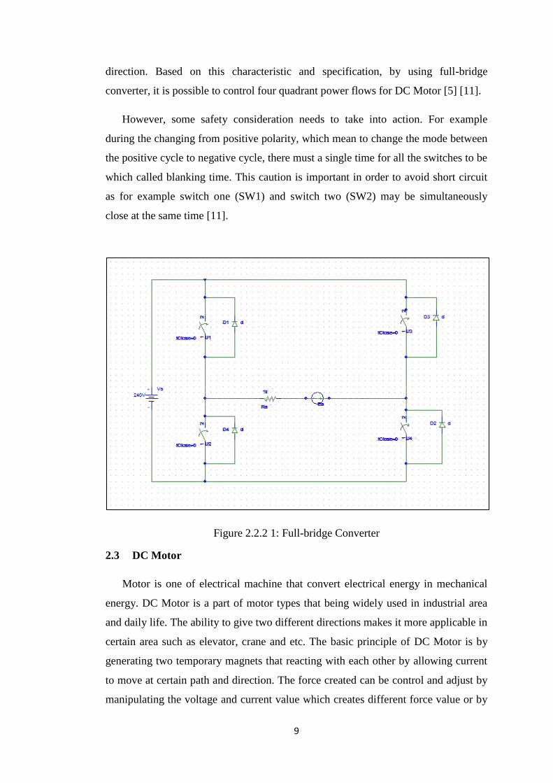
2.3.1 Shunt DC Motor
Shunt DC Motor has a parallel winding between it armature winding and
field winding [7] [9]. This way of connection makes sure that the induction voltage
and field voltage always equally have the same and balance each other. The most
advantage of shunt DC Motor is its ability to operate at constant speed. However, it
is not advisable to be used in the heavy load process.
As it is parallel connected, the voltage drop is not affected by the field part.
Based on voltage division, the loop can be viewed as equation (3)
(3)
Where is equal to armature voltage, is equal to Induction voltage, is equal to
armature current, and is equal to armature resistant [7] [17]. The induction
voltage then can be simplified by this equation (4)
(4)
Where is equal to induction voltage, is equal to armature constant and N is
equal to the speed of the motor [11]. Based on both equations, by rearrange the
equation the armature constant can then be calculated and found.
(5)
11
The equivalent circuit of Shunt DC Motor is as follow:
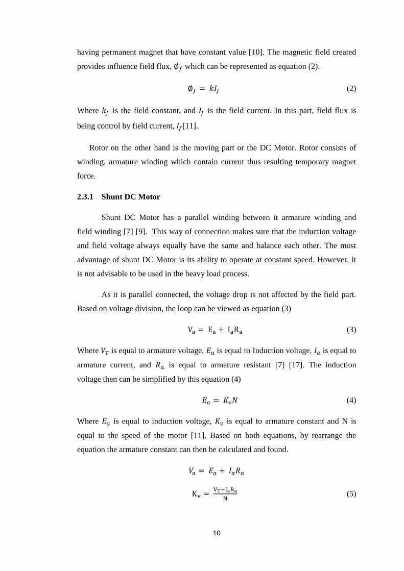
2.3.2 Series DC Motor
DC series motor is one of dc motor type. Compare with the other types,
Series DC Motor series connection between field winding and armature winding [7]
[10]. Difference winding connection gives DC Motor difference advantage compare
with the other type. Due to this condition DC Motor is suitable to use for high torque
function such as elevator and crane. However DC Motor have a very high changing
speed between different load thus makes it harder to keep at a constant speed which
make it not suitable to use in constant speed functionality. More than that, it is
necessary to have load when using DC Motor as without load will make the motor
speed keep increasing thus damage the motor [10]. Due to series arrangement,
voltage division can be seen in equation (6).
(6)
Where is equal to armature voltage, is equal to Induction voltage, is equal to
armature current, is equal to armature resistant and is equal to field resistant
[7]. Additional to that, induction voltage can be calculated by another related
equation (7)
(7)
Figure 2.3. 1: Shunt DC Motor Equivalent Circuit
12
Where is equal to induction voltage, is equal to armature constant, is equal
to flux constant, is equal to armature current and N is equal to the speed of the
motor [13]. By rearrange all the equation, the constants, can be found.
(8)
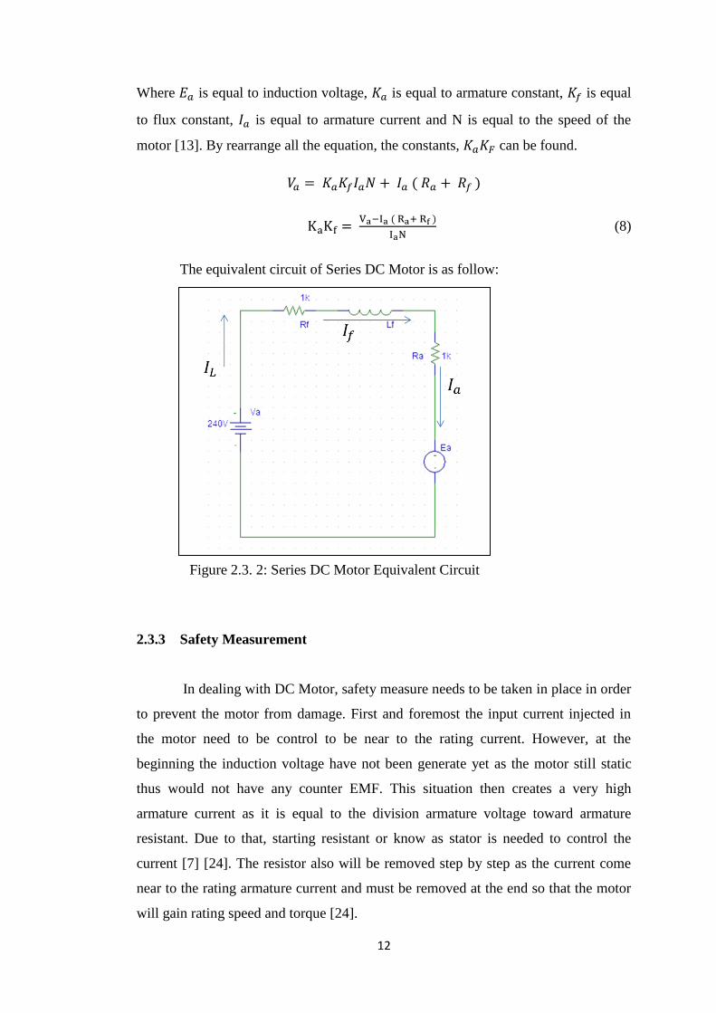
The equivalent circuit of Series DC Motor is as follow:
2.3.3 Safety Measurement
In dealing with DC Motor, safety measure needs to be taken in place in order
to prevent the motor from damage. First and foremost the input current injected in
the motor need to be control to be near to the rating current. However, at the
beginning the induction voltage have not been generate yet as the motor still static
thus would not have any counter EMF. This situation then creates a very high
armature current as it is equal to the division armature voltage toward armature
resistant. Due to that, starting resistant or know as stator is needed to control the
current [7] [24]. The resistor also will be removed step by step as the current come
near to the rating armature current and must be removed at the end so that the motor
will gain rating speed and torque [24].
Figure 2.3. 2: Series DC Motor Equivalent Circuit
13
Besides that, breaking procedure need also to be well implicate in order to
save the DC Motor thus keep in during it life span. In order to do so, the breaking
process needs to be conduct slowly and step by step. Removing the armature voltage
directly is not the right way to do it as the armature current will be too high thus
damage the DC Motor. Due to that, instead of removing the armature voltage thus
give zero armature voltage, the armature voltage need to be slowly reduced to lower
than inductive voltage. The circuit then will give negative armature current. The DC
Motor will like as a generator and reduce it speed. The process keep continue until
the inductive voltage become zero which represent that the motor already stopped
[21].
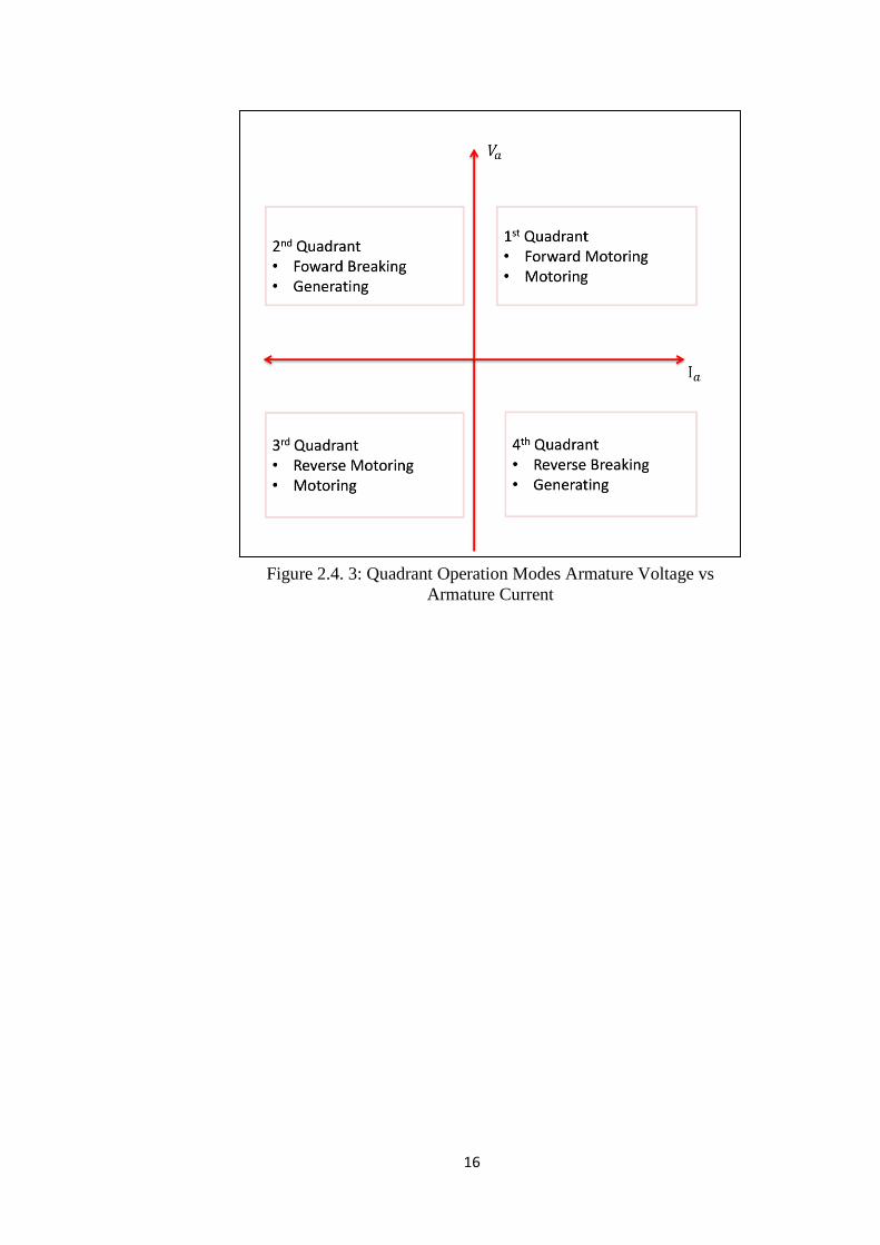
2.4 Four Quadrant Operations
Both converter operation and DC Motor drive operation mention about Four
Quadrant Operations. This is because both converter operation and DC Motor drive
operation are interacting with each other. In converter operation, the voltage output
and current output is the ones that define quadrant position where else DC Motor
drive is more on motor’s torque versus motor’s speed. The four quadrant operations
are named based on the sequence.
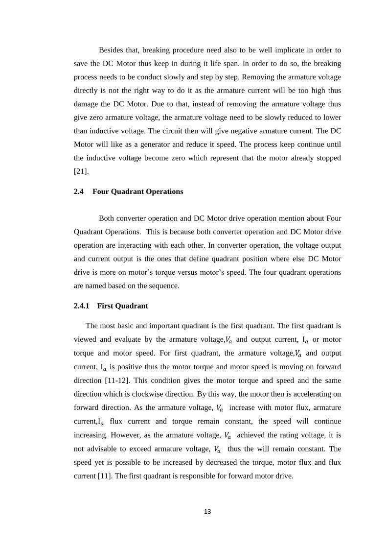
2.4.1 First Quadrant
The most basic and important quadrant is the first quadrant. The first quadrant is
viewed and evaluate by the armature voltage, and output current, or motor
torque and motor speed. For first quadrant, the armature voltage, and output
current, is positive thus the motor torque and motor speed is moving on forward
direction [11-12]. This condition gives the motor torque and speed and the same
direction which is clockwise direction. By this way, the motor then is accelerating on
forward direction. As the armature voltage, increase with motor flux, armature
current, flux current and torque remain constant, the speed will continue
increasing. However, as the armature voltage, achieved the rating voltage, it is
not advisable to exceed armature voltage, thus the will remain constant. The
speed yet is possible to be increased by decreased the torque, motor flux and flux
current [11]. The first quadrant is responsible for forward motor drive.
14
2.4.2 Second Quadrant
The second quadrant is responsible for forward breaking. During this moment,
the armature voltage, given is lower than induction voltage, these condition
make the motor react as generator. Due to that, the armature current, will be
negative as it coming from the induction voltage instead of the armature voltage [11-
12]. The torque direction and speed direction will move on different direction. The
torque direction is moving on counter clockwise where else the speed is on clock
wise direction [3]. The motor then will decelerate and slowing down.
2.4.3 Third Quadrant
Third quadrant operation is almost equal with the first quadrant except the third
quadrant is the inverse of the first quadrant. By the way, it’s mean that the armature
voltage, of the motor drive will be negative. This situation then will inject
negative armature current, toward the system [11-12]. The torque, T and speed of
the motor will be on counter clockwise direction [11]. The motor will accelerate until
certain speed.
2.4.4 Forth Quadrant
As the third quadrant is inverse of first quadrant, the forth quadrant is inverse of
second quadrant. Although the armature voltage given is negative, the inductive
Figure 2.4. 1: Forward Drive Characteristic Graph vs. Speed
15
voltage is more negative than the armature voltage. This situation makes the
armature current move on positive direction which is from induction voltage to
armature voltage [11-12]. The torque and speed will counter each other. The torque
will be on clockwise direction where else the speed is on counter clock direction
[11]. The motor will then decelerate and slowing down.
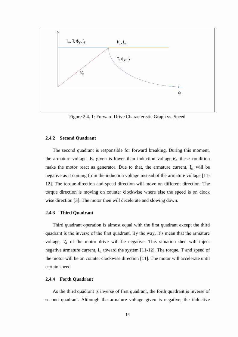
The four quadrant operation for the system is summarized ain fig 2.4.2 and figure
2.4.3.
Figure 2.4. 2Quadrant Operation Modes Speed vs. Torque
16
Figure 2.4. 3: Quadrant Operation Modes Armature Voltage vs
Armature Current
17
CHAPTER 3: METHODOLOGY
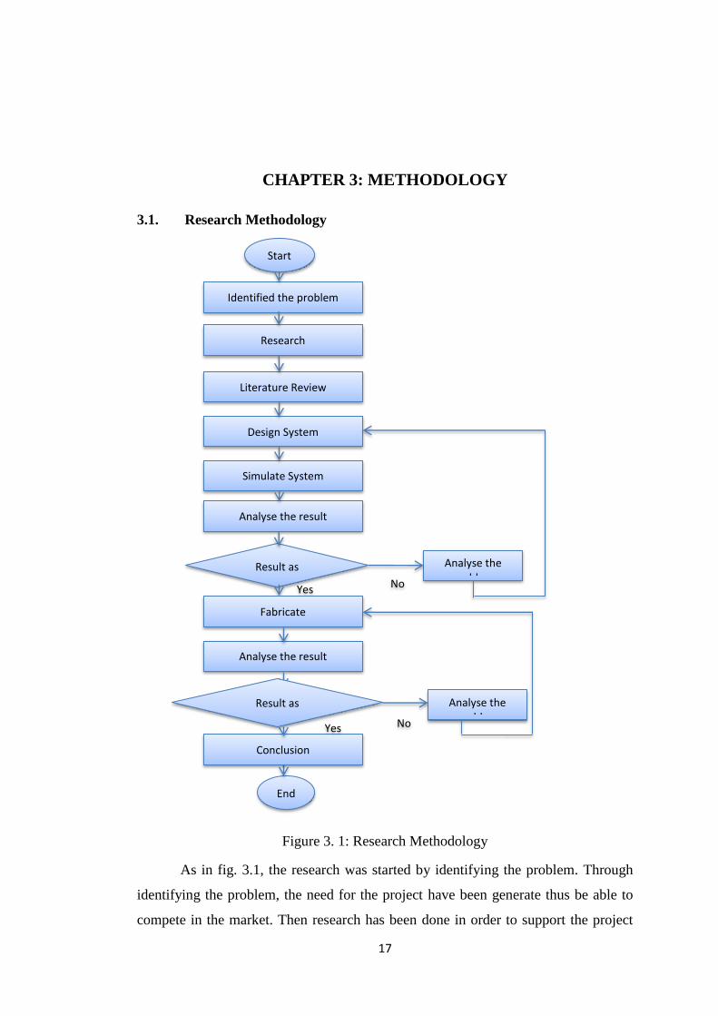
3.1. Research Methodology
Figure 3. 1: Research Methodology
As in fig. 3.1, the research was started by identifying the problem. Through
identifying the problem, the need for the project have been generate thus be able to
compete in the market. Then research has been done in order to support the project
Start
Literature Review
Research
Identified the problem
Simulate System
Design System
End
Result as expected
Analyse the result
Analyse the problem
Yes No
Fabricate
Analyse the result
Analyse the problem
Conclusion
Yes No
Result as expected
18
needs. By doing research also more detail on the project has be known. The
important data such as constant value and important steps has being gained. The data
achieved then been collected and compiled in a single document which called
literature review. In literature review, the similarity of the information been seen and
support each other thus make a stronger base.
After that, important system specification been extracted from the data in
order to make the design follow the requirement needed. Based on the design
specification, the system then continue being design and being fabricated in the
simulation software. The system then being simulate thus be able to demonstrate a
step to be real product. The result then being analysed, if the result is as expected, the
system can be fabricated, if the result is not expected, more analyses will be
conducted and the simulation will be redone. After being fabricated, the fabricating
output will the again being analysed either it is as expected or not as expected. If the
result is correct, the project can be concluded. On the other hand, if the result is not
as expected, further study on the result will be conducted and the loop will be
continue until the result is satisfied.
3.2. Project activities
The project was begun by doing the research in order to gain knowledge on
the involved field. The research was on DC Motor, converter, four quadrant system,
and Fuzzy Logic Controller (FLC). The project then continued on collecting the data
from the hardware instrument which the DC Motor and the full-bridge converter. By
doing so, the experiments and design will be according to the desired instrument.
After that, simulation on the conventional control system being conducted
which by using Proportional Integral (PI) feedback controller to control DC Motor.
The system must be sure simulated properly and taking cared on every safety aspect.
The project activities then was continued by fabricating the conventional DC
Motor controller which by using PI Controller. This fabricating is important in order
to understanding the basic principle of conventional controller besides being able to
prepare a benchmark for the new designed controller.
Next, the Fuzzy Logic Controller then was designed and fabricated. The new
controller was designed by using microcontroller, PIC16F877A, as it main controller
part. Then the comparison between conventional controller and Fuzzy Logic
19
Controller on the both performance has been conducted. This comparison is
important to ensure that the new controller can give better performance compare with
conventional controller.
3.3 Program Sequence
As the whole system was controlled by the microcontroller, PIC16F877A, the
programming part is major part of this project. The programming was done by using
MPLAB and using C language.
The programming sequence is been built based on Fuzzy Logic Theory thus
create Fuzzy Logic Controller. The program at the beginning will compare the
between the desired value (Sp) and resulting value (Mv). If the value is equal, which
mean the desired value (Sp) is the resulting value (Mv), the action will be maintained
which mean the current armature voltage, Va will remain the same. This state is
labelled as Zero Error (ZE).
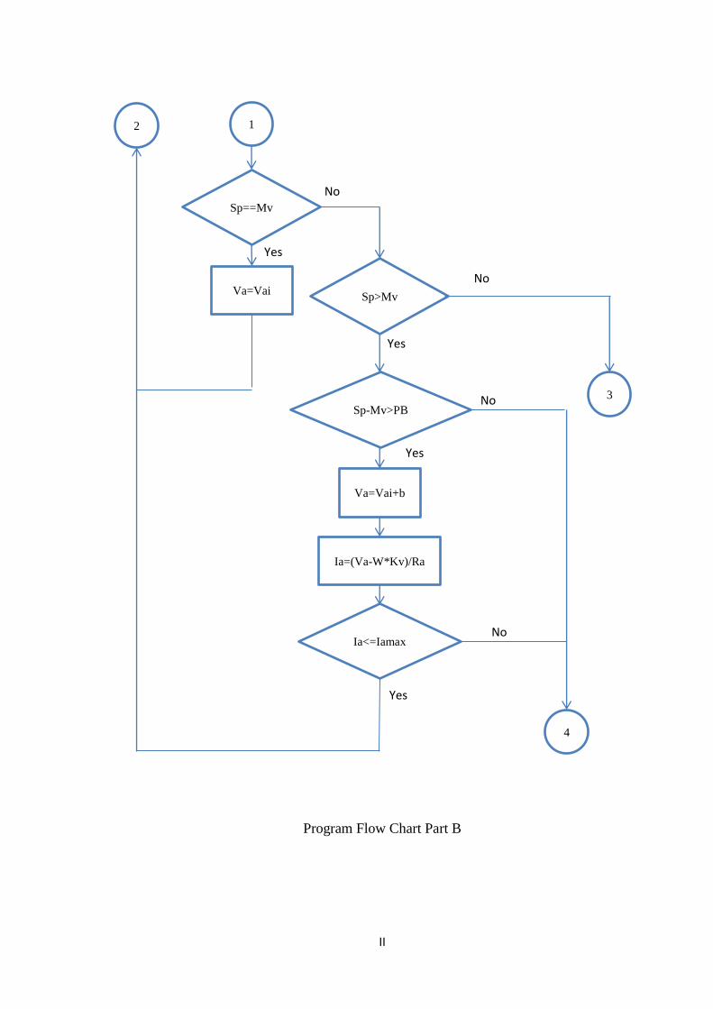
On the other hand, if SP is higher than Mv, the Va will be changed. The next
comparison then will be conducted in order to know in which type is the different. If
the different is big, the state will be labelled as Positive Big (PB), if it is medium, it
will be Positive Medium (PM) and Positive Small (PS) is for small error. Big
additional armature voltage will be fed in PB state, medium changes in PM and small
additional value in the armature voltage in PS. However, the armature current, Ia also
need to be considered, on each state the Ia need to be ensured below the maximum
armature current, Iamax allowed. The Ia can be found as equation (9)
(9)
Where Ia is equal to armature current, Va is armature voltage, Ra is armature
resistant, Kv is back EMF constant, and is the motor speed in radian per second.
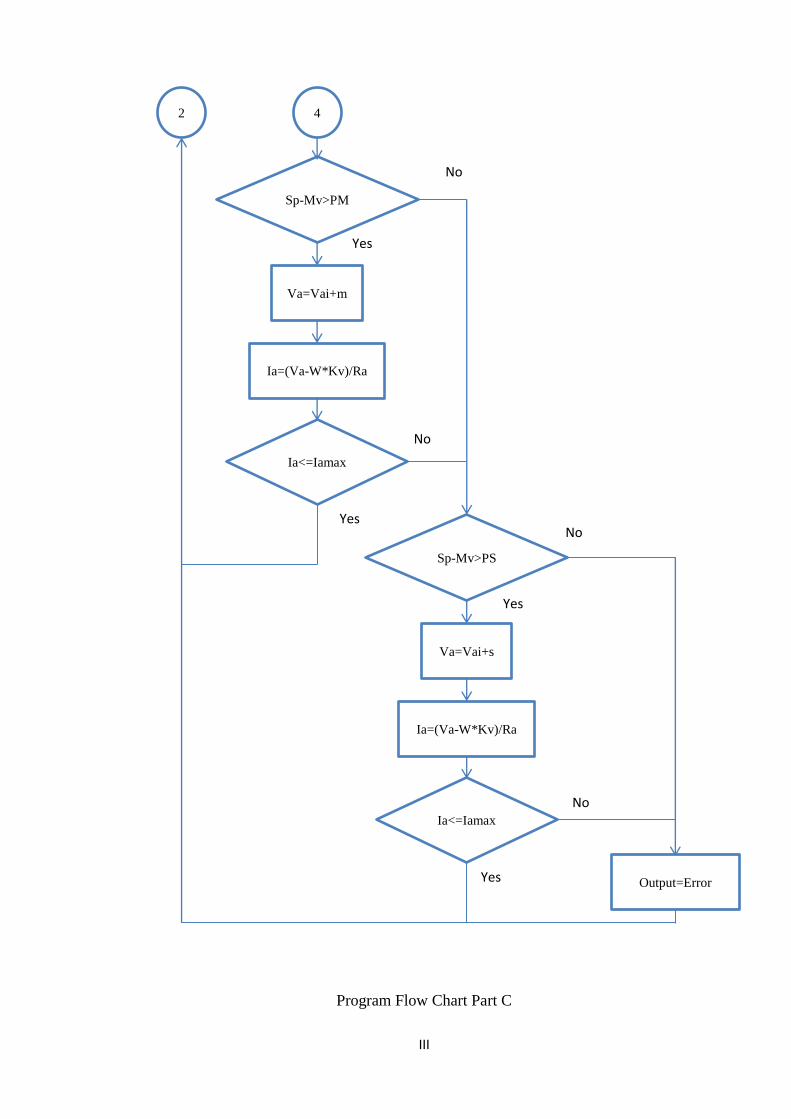
By this condition, if the changes on armature voltage, Va is too big and exceed
maximum armature current, the state will be change to the next lower state. For
example, if the speed different is big and the state should be in Positive Big (PB) but
the calculated value for armature current, Ia will exceed the maximum value allowed,
the state for that condition will move to Positive Medium (PM) and will continue
until the armature current under the safe range.
20
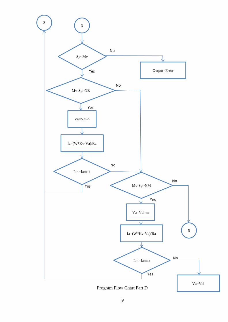
However, if the Mv is higher than Sp, the situation is different. If the
difference is big the state will be Negative Big (NB), if it is medium it will be
Negative Medium (NM) and it will be Negative Small (NS) for small difference.
When the condition is NB, big value will be deducted from the current Va, medium
value for NM and small value for NS. The Ia again need to be ensure below Iamax in
order to avoid damaging the motor. The Ia direction however is inverse of normal Ia
direction as the Back EMF is higher than the Va thus will make the current flow
from the motor. The absolute Ia can be calculate based on the equation (10).
(10)
Where Ia is equal to armature current, Va is armature voltage, Ra is armature
resistant, Kv is back EMF constant, and is the motor speed in radian per second.
This condition is breaking condition. In order to avoid that the armature current
might exceed the maximum value allowed, the same procedure during acceleration
condition also been conducted in breaking condition.
As the breaking happened, the armature voltage, Ia will be lower than back
EMF value. However, if the difference is too big, the armature current will exceed
the allowed range. In order to counter this problem, the state for this condition will
move to the lower state. For example, if based on the speed difference, the state
should be Negative Big (NB); however the armature current, Ia was calculated to
exceed the maximum armature current value. Due to this condition, the state will
change to Negative Medium (NM). The program sequence is visualized as in the
flow chart as Appendix A.
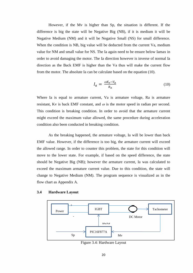
3.4 Hardware Layout
Figure 3.4: Hardware Layout
Power Supply
IGBT
PIC16F877A
+
-
DC Motor
Tachometer
Mv Sp
PWM

21
As shown in fig. 3.4, the power supply will provide 240 VDC toward the
IGBT and then connected to the DC Motor. The IGBT will react as switch to control
the motor either to turn it ON or OFF. The IGBT input will be controlled the Pulse
Width Modulation (PWM) from the Programmable Interface Circuit (PIC). The PIC
will give PWM value which are 0v and 5v to ON and OFF the IGBT based on the
output wanted to be generated. The tachometer was connected with the DC Motor,
the tachometer is to convert the kinetic energy in the motor speed to voltage value to
be able to use by the PIC for further process. The PIC then will use reference speed
value from the tachometer and desired value from the user to control the motor
speed.

22
3.4. Gant Chart and Milestone for FYP 1
Table 3.3: Gant Chart and Milestone
No Activities Details \ Week 1 2 3 4 5 6 7 8 9 10 11 12 13 14
1 Title Selection
2 Preliminary Research Work
3 Extended Proposal Submission
4 Simulation on Conventional Control System
5 Proposal Defence
6 Analysing on The Result
7 Draft Report Submission
8 Final Report Submission
Process
Suggested

23
3.5. Gant Chart and Milestone for FYP 2
Table 3.4: Gant Chart and Milestone for FYP 2
No Activities Details \ Week 1 2 3 4 5 6 7 8 9 10 11 12 13 14
1 Model Development and Modification Work
2 Testing and Validation work
3 Submission of Progress Report
4 Results Analysis and Discussion
5 Pre-EDX
6 Submission of Draft Report
7 Submission of Dissertation
8 Submission of Technical Paper
9 Oral Presentation
10 Submission of Project Dissertation
Process
Suggested
24
3.6. Tools Used
The import tool that was being used in simulation part is Simulink which is a
part of MATLAB version R2011a. MATLAB and Simulink are registered under
MathWorks, Inc. Simulink is important in order to simulate the whole control system
by using Simulink Library Tools.
One of the most important parts in the prototype is PIC16F877A which is a
microcontroller produce by Microchip. This chip is important in order to programme
the controller according to the desire system. The next instrument is PIC Start-up kit,
SK400C and PIC Programmer which use to load the program into the PIC. The PIC
however was programmed using MPLAB which was license under Microchip
Technology Inc.
The next instrument the prototype is Lab-Volt Model 8837-B – IGBT
Chopper/Inverter, Model 8211 – DC Motor/Generator, and Model 8931 – Speed
Sensor / Tachometer.
25
CHAPTER 4: RESULT AND DISCUSSION
4.1 Extracting Data from Instruments
Armature Speed, Ra= 31Ω
Trial Speed, ω =
= 107.33 radian/second
Armature Current, Ia = 80mA
Maximum Armature Current, Iamax=2.2A
Armature Voltage, Va= 192 V
Back EMF constant value, Kv=
(11)
= 1.765 vs/rad
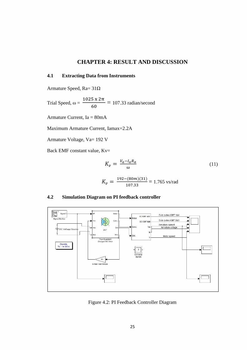
4.2 Simulation Diagram on PI feedback controller
Figure 4.2: PI Feedback Controller Diagram
26
In order to visualize the conventional DC Motor control, the diagram to
generate conventional type of speed output been generate first. In this diagram (fig
4.2), the given input will be steps changes of different speed reference which will be
send to the controller. The controller then will control the PWM circuit and control
the output of the full-bridge circuit which control the average output given to the
motor. The current motor speed then will fed back to the PI controller and will be
compared with set point in order to achieve the set point.
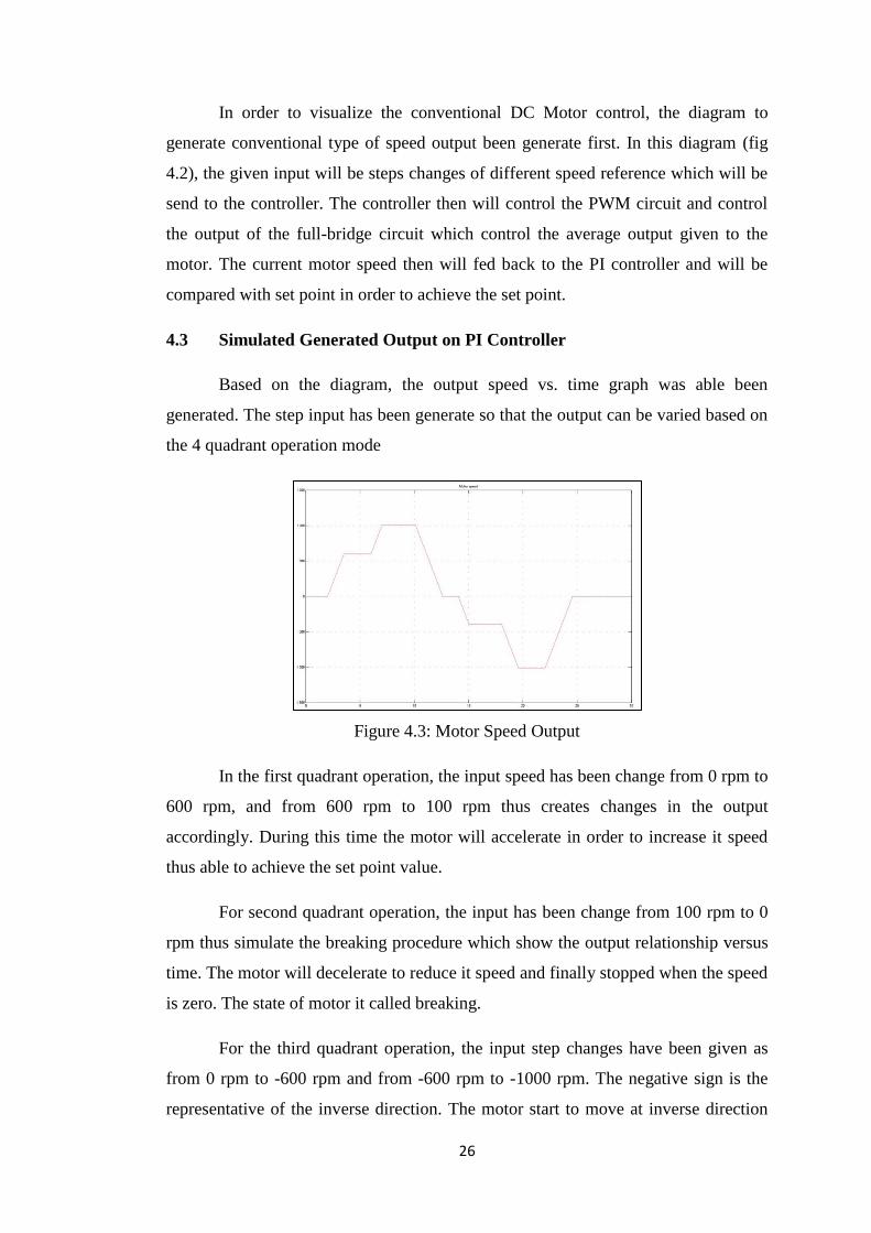
4.3 Simulated Generated Output on PI Controller
Based on the diagram, the output speed vs. time graph was able been
generated. The step input has been generate so that the output can be varied based on
the 4 quadrant operation mode
Figure 4.3: Motor Speed Output
In the first quadrant operation, the input speed has been change from 0 rpm to
600 rpm, and from 600 rpm to 100 rpm thus creates changes in the output
accordingly. During this time the motor will accelerate in order to increase it speed
thus able to achieve the set point value.
For second quadrant operation, the input has been change from 100 rpm to 0
rpm thus simulate the breaking procedure which show the output relationship versus
time. The motor will decelerate to reduce it speed and finally stopped when the speed
is zero. The state of motor it called breaking.
For the third quadrant operation, the input step changes have been given as
from 0 rpm to -600 rpm and from -600 rpm to -1000 rpm. The negative sign is the
representative of the inverse direction. The motor start to move at inverse direction
27
and accelerating until it able to achieve the desired value and continuingly
maintained it speed.
For the fourth quadrant operation, the breaking process occurs in the inverse
direction as the motor is breaking from -1000 rpm to 0 rpm. After moving at inverse
direction the set point has been set so that the motor will break from the reverse
direction. The motor will decelerate until the speed is zero and would not move until
new speed has been set up at the set point.
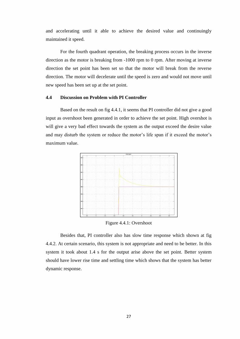
4.4 Discussion on Problem with PI Controller
Based on the result on fig 4.4.1, it seems that PI controller did not give a good
input as overshoot been generated in order to achieve the set point. High overshot is
will give a very bad effect towards the system as the output exceed the desire value
and may disturb the system or reduce the motor’s life span if it exceed the motor’s
maximum value.
Figure 4.4.1: Overshoot
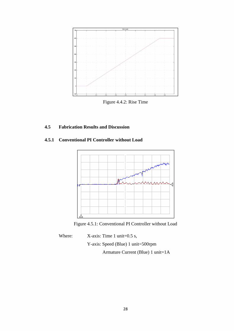
Besides that, PI controller also has slow time response which shown at fig
4.4.2. At certain scenario, this system is not appropriate and need to be better. In this
system it took about 1.4 s for the output arise above the set point. Better system
should have lower rise time and settling time which shows that the system has better
dynamic response.
28
Figure 4.4.2: Rise Time
4.5 Fabrication Results and Discussion
4.5.1 Conventional PI Controller without Load
Figure 4.5.1: Conventional PI Controller without Load
Where: X-axis: Time 1 unit=0.5 s,
Y-axis: Speed (Blue) 1 unit=500rpm
Armature Current (Blue) 1 unit=1A
29
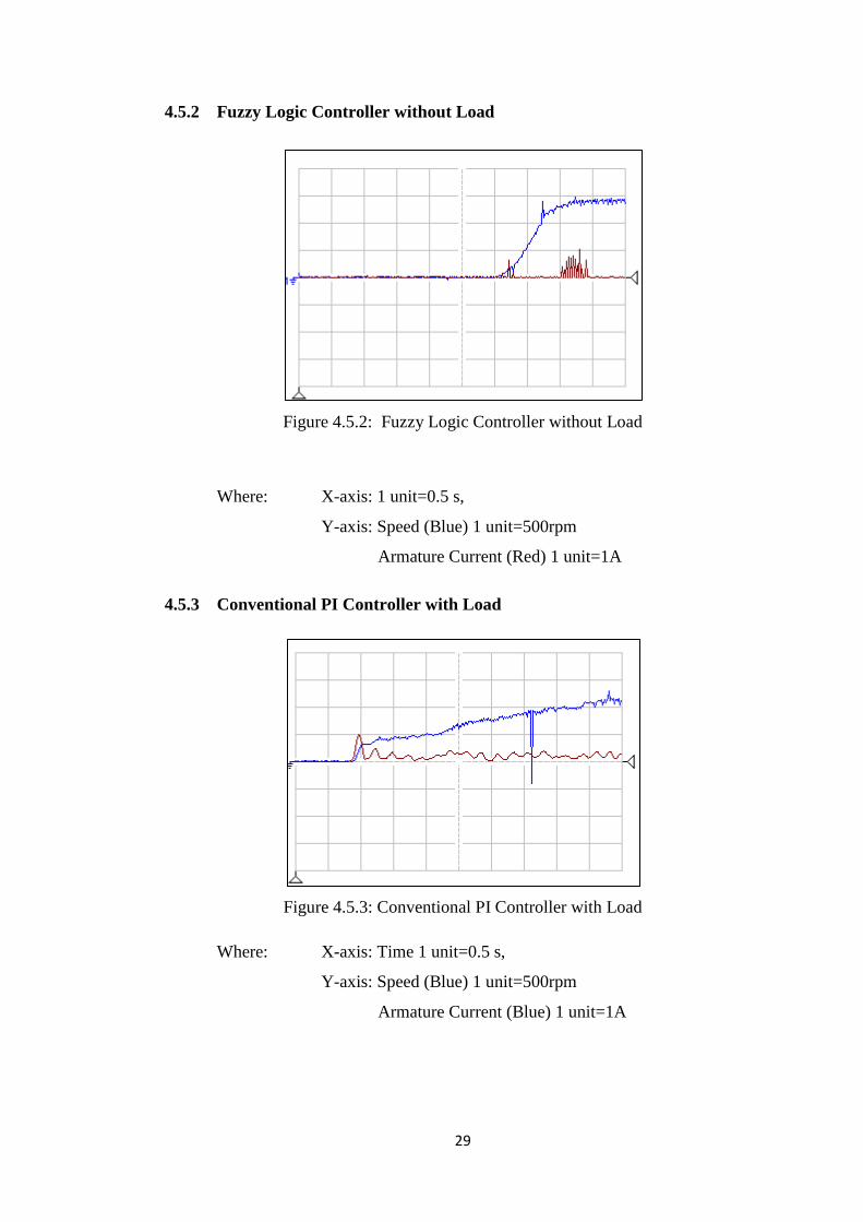
4.5.2 Fuzzy Logic Controller without Load
Figure 4.5.2: Fuzzy Logic Controller without Load
Where: X-axis: 1 unit=0.5 s,
Y-axis: Speed (Blue) 1 unit=500rpm
Armature Current (Red) 1 unit=1A
4.5.3 Conventional PI Controller with Load
Figure 4.5.3: Conventional PI Controller with Load
Where: X-axis: Time 1 unit=0.5 s,
Y-axis: Speed (Blue) 1 unit=500rpm
Armature Current (Blue) 1 unit=1A
30
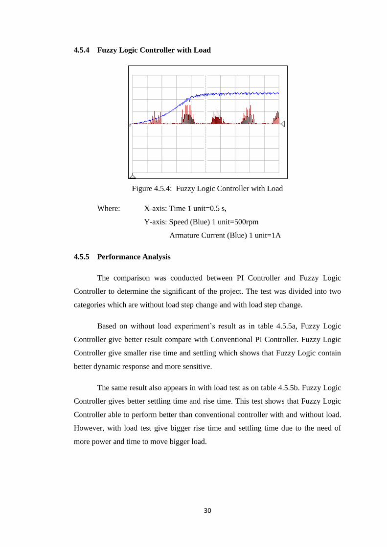
4.5.4 Fuzzy Logic Controller with Load
Figure 4.5.4: Fuzzy Logic Controller with Load
Where: X-axis: Time 1 unit=0.5 s,
Y-axis: Speed (Blue) 1 unit=500rpm
Armature Current (Blue) 1 unit=1A
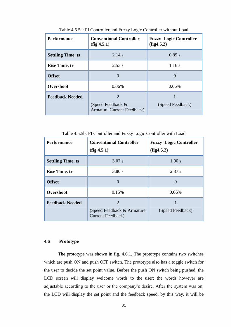
4.5.5 Performance Analysis
The comparison was conducted between PI Controller and Fuzzy Logic
Controller to determine the significant of the project. The test was divided into two
categories which are without load step change and with load step change.
Based on without load experiment’s result as in table 4.5.5a, Fuzzy Logic
Controller give better result compare with Conventional PI Controller. Fuzzy Logic
Controller give smaller rise time and settling which shows that Fuzzy Logic contain
better dynamic response and more sensitive.
The same result also appears in with load test as on table 4.5.5b. Fuzzy Logic
Controller gives better settling time and rise time. This test shows that Fuzzy Logic
Controller able to perform better than conventional controller with and without load.
However, with load test give bigger rise time and settling time due to the need of
more power and time to move bigger load.
31
Table 4.5.5a: PI Controller and Fuzzy Logic Controller without Load
Performance Conventional Controller
(fig 4.5.1)
Fuzzy Logic Controller
(fig4.5.2)
Settling Time, ts 2.14 s 0.89 s
Rise Time, tr 2.53 s 1.16 s
Offset 0 0
Overshoot 0.06% 0.06%
Feedback Needed 2
(Speed Feedback &
Armature Current Feedback)
1
(Speed Feedback)
Table 4.5.5b: PI Controller and Fuzzy Logic Controller with Load
Performance Conventional Controller
(fig 4.5.1)
Fuzzy Logic Controller
(fig4.5.2)
Settling Time, ts 3.07 s 1.90 s
Rise Time, tr 3.80 s 2.37 s
Offset 0 0
Overshoot 0.15% 0.06%
Feedback Needed 2
(Speed Feedback & Armature
Current Feedback)
1
(Speed Feedback)
4.6 Prototype
The prototype was shown in fig. 4.6.1. The prototype contains two switches
which are push ON and push OFF switch. The prototype also has a toggle switch for
the user to decide the set point value. Before the push ON switch being pushed, the
LCD screen will display welcome words to the user; the words however are
adjustable according to the user or the company’s desire. After the system was on,
the LCD will display the set point and the feedback speed, by this way, it will be
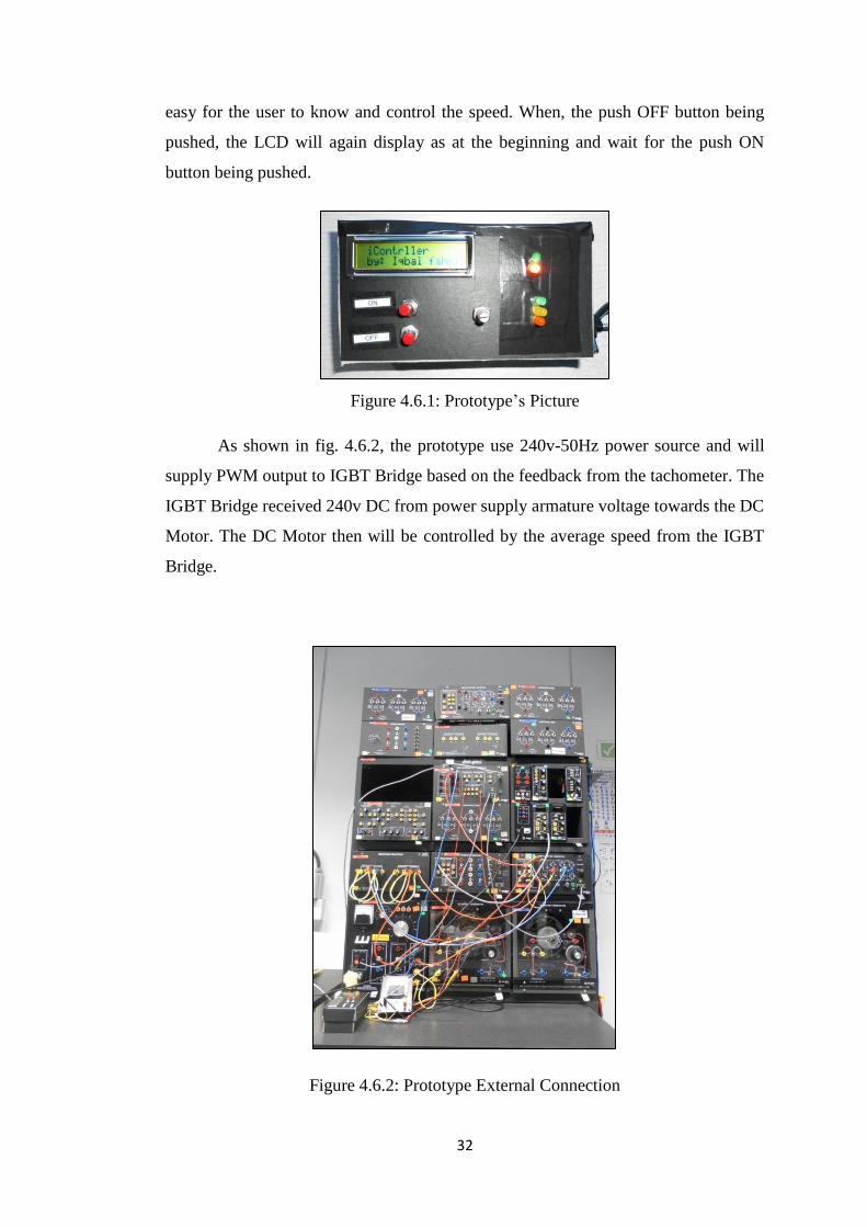
32
easy for the user to know and control the speed. When, the push OFF button being
pushed, the LCD will again display as at the beginning and wait for the push ON
button being pushed.
Figure 4.6.1: Prototype’s Picture
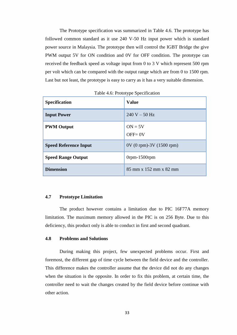
As shown in fig. 4.6.2, the prototype use 240v-50Hz power source and will
supply PWM output to IGBT Bridge based on the feedback from the tachometer. The
IGBT Bridge received 240v DC from power supply armature voltage towards the DC
Motor. The DC Motor then will be controlled by the average speed from the IGBT
Bridge.
Figure 4.6.2: Prototype External Connection
33
The Prototype specification was summarized in Table 4.6. The prototype has
followed common standard as it use 240 V-50 Hz input power which is standard
power source in Malaysia. The prototype then will control the IGBT Bridge the give
PWM output 5V for ON condition and 0V for OFF condition. The prototype can
received the feedback speed as voltage input from 0 to 3 V which represent 500 rpm
per volt which can be compared with the output range which are from 0 to 1500 rpm.
Last but not least, the prototype is easy to carry as it has a very suitable dimension.
Table 4.6: Prototype Specification
Specification Value
Input Power 240 V – 50 Hz
PWM Output ON = 5V
OFF= 0V
Speed Reference Input 0V (0 rpm)-3V (1500 rpm)
Speed Range Output 0rpm-1500rpm
Dimension 85 mm x 152 mm x 82 mm
4.7 Prototype Limitation
The product however contains a limitation due to PIC 16F77A memory
limitation. The maximum memory allowed in the PIC is on 256 Byte. Due to this
deficiency, this product only is able to conduct in first and second quadrant.
4.8 Problems and Solutions
During making this project, few unexpected problems occur. First and
foremost, the different gap of time cycle between the field device and the controller.
This difference makes the controller assume that the device did not do any changes
when the situation is the opposite. In order to fix this problem, at certain time, the
controller need to wait the changes created by the field device before continue with
other action.
34
CHAPTER 5: CONCLUSION
5.1 Relevancy to the Objectives
Current DC Motor control use Proportional Integral (PI) Controller and the
speed controller. However, the conventional controller is hard to be tuned and
without proper tune the performance will not be optimized besides will give bad
effect towards the system.
In order to counter this issue, a new controller using Fuzzy Logic Theory was
generated to give better performance besides to upgrade the other ability. Fuzzy
Logic Controller use human-like method to control the speed makes the system
simpler and easy to be understood.
Based on the result, Fuzzy Logic Controller generated better performance
compare conventional Proportional Integral (PI) Controller react better in speed
control. This outcome concludes that the newly generated controller is a successful
project.
5.2 Suggested Future Work for Expansion and Continuation
Proportional Integral (PI) has been well established as the best controller for
speed controller. However, the new technology has generated new ways and methods
to control the speed. New intelligent control’s methods have keep generate time to
time. Excluding using Fuzzy Logic Theory to create the controller, other intelligent
control theory would like to suggest such as Neural Network Controller (ANN) [2],
Model Predictive Controller (MPC) [3], Genetic Algorithm (GA) [22] and Fuzzy
Logic Controller (FLC) [23]. These deferent algorithms have different approach in
controlling the system thus will give different result. By doing so then the best
controller for each device can be create and give the best performance for the system.
35
REFERENCES
[1] Aissaoui, A., Abid, M., Abid, H., Tahour, A., & Zeblah, A. (2007). A Fuzzy
Logic Controller for Synchronous Machine. Journal of Electrical
Engineering, 285-290.
[2] Krogh, A. (2008). What are Artificial Neural Network? Nature Biotechnology,
195-197.
[3] Mayne, D. Q., Rawling, J. B., Rao, C. V., & Scokaert, P. M. (2000). Constrained
Model Predictive Control: Stability and Optimality. Automatica, 789-814.
[4] Natsheh, E., & Buragga, K. A. (2010). Comparison between Conventional and
Fuzzy Logic PID Controller for Controlling DC Motors. International Journal
of Computer Science Issues, 128-134.
[5] Patil, S. S., & Bhaskar, P. (2009). Design and Real Time Implementation of
Integrated Fuzzy Logic Controller for a High Speed PMCD Motor.
International Journal of Electronic Engineering Research, 13-25.
[6] Wahid, N., Hassan, N., Rahmat, M., & Mansor, S. (2011). Application of
Intelligent Controller in Feedback Control Loop for Aircraft Pitch Control.
Australian Journal of Basic and Applied Sciences, 1065-1074.
[7] Chapman, S. J. (2005). Electric Machinery Fundelmentals. Singapore: McGraw-
Hill.
[8] Kazimierczuk, M. K. (2008). Pulse-width Modulated DC-DC Power Converters.
United Kingdom: John Wiley and Sons, Ltd, Publication.
[9] Marlin, T. E. (2000). Process Control. Singapore: McGraw-Hill Book Co.
[10] Miller, R., & Miller, M. R. (2008). Industrial Electricity and Motor Controls.
United State: McGraw-Hill.
[11] Mohan, N., Undeland, T. M., & Robbins, W. P. (2003). Power Electronics.
United Stated: John Wiley & Sons, Inc.
[12] Rashid, M. H. (2004). Power Electronics, Circuits, Devices, and Applications.
United States of America: Pearson Education Education, Inc.
36
[13] Ross, T. J. (2010). Fuzzy Logic with Engineering Application. United Kingdom:
John Wiley & Sons, Ltd.
[14] Bellur, D.M.; Kazimierczuk, M.K.; , "DC-DC converters for electric vehicle
applications," Electrical Insulation Conference and Electrical Manufacturing
Expo, 2007 , vol., no., pp.286-293, 22-24 Oct. 2007
doi: 10.1109/EEIC.2007.4562633
URL: http://ieeexplore.ieee.org/stamp/stamp.jsp?tp=&arnumber=4562633&is
number=4562569
[15] Chen Xu; Dagui Huang; Yiping Huang; Shugang Gong; , "Digital PID
controller for Brushless DC Motor based on AVR microcontroller,"
Mechatronics and Automation, 2008. ICMA 2008. IEEE International
Conference on , vol., no., pp.247-252, 5-8 Aug. 2008
doi: 10.1109/ICMA.2008.4798760
URL:http://ieeexplore.ieee.org/stamp/stamp.jsp?tp=&arnumber=4798760&is
number=4798708
[16] Chuen, C. L. 1990, “Fuzzy Logic in Control Systems: Fuzzy Logic Controller-
Part I,” IEEE Transactions On Systems, Man and Cybernetics: 404
[17] Sahoo, N. C. (n.d.). DC Drives. Universiti Teknologi Petronas, Tronoh.
[18] Shaker, M.M.; Al-khashab, Y.M.B.I.; , "Design and implementation of fuzzy
logic system for DC Motor speed control," Energy, Power and Control (EPC-
IQ), 2010 1st International Conference on , vol., no., pp.123-130, Nov. 30
2010-Dec. 2 2010
URL: http://ieeexplore.ieee.org/stamp/stamp.jsp?tp=&arnumber=5767298&is
number=5767290
[19] Sofian, Y.; Iyas, M.; , "Design of electronic load controller for a self excited
induction generator using fuzzy logic method based
microcontroller," Electrical Engineering and Informatics (ICEEI), 2011
International Conference on , vol., no., pp.1-6, 17-19 July 2011
doi:10.1109/ICEEI.2011.6021725
URL: http://ieeexplore.ieee.org/stamp/stamp.jsp?tp=&arnumber=6021725&is
number=6021499
37
[21] Xiaoping W., Yunliang Z. and Yuanqing L. 2011, “Dynamic Performance
Analysis of PID Controller with one Memristor,” International Conference on
Information Science and Technology: 1234
[22] Wahyunggoro, O. (2011). Optimization of Hybrid-Fuzzy Controller for
Servormotor Control using Modified Genetic Algorithm. Tronoh: Universiti
Teknologi Petronas.
[23] Abdul Aziz, A. (2011). Modelling and Advanced Control Studies on Heat
Exchanger Pilot Plant. Tronoh, Perak: Universiti Teknologi Petronas.
[24] Vasudevan, K., Rao, G., & Rao, P. (n.d.). Electrical Machines I. Retrieved
Febuary 14, 2012, from National Programme on Technology Enhanced
Learning:http://nptel.iitm.ac.in/courses/IIT
MADRAS/Electrical_Machines_I/pdfs/2_1.pdf
[25] Hajek, Petr, "Fuzzy Logic", The Stanford Encyclopedia of Philosophy (Fall
2010 Edition), Edward N. Zalta (ed.),
URL:http://plato.stanford.edu/archives/fall2010/entries/logic-fuzzy/.
I
Appendix A: Program Flow Chart
Program Flow Chart Part A
Initialize variable
Ploop=0
Nloop=0
Start
ONSW
= 1
Get ONSW condition,
Set Va=0,
Vai=0
Get Sp,
Mv
1 2
Output= Va
Yes
No
II
Program Flow Chart Part B
Sp==Mv
Va=Vai
1 2
Sp>Mv
3
Sp-Mv>PB
Va=Vai+b
Ia=(Va-W*Kv)/Ra
Ia<=Iamax
4
Yes
No
Yes
No
Yes
No
Yes
No
III
Program Flow Chart Part C
Sp-Mv>PM
Va=Vai+m
Ia=(Va-W*Kv)/Ra
Ia<=Iamax
4 2
Sp-Mv>PS
Va=Vai+s
Ia=(Va-W*Kv)/Ra
Ia<=Iamax
Output=Error
Yes
No
Yes
No
Yes
No
Yes
No
IV
Program Flow Chart Part D
3 2
Sp<Mv
Mv-Sp>NB
Va=Vai-b
Ia=(W*Kv-Va)/Ra
Ia<=Iamax
Output=Error
Mv-Sp>NM
Va=Vai-m
Ia=(W*Kv-Va)/Ra
Ia<=Iamax
5
Yes
No
Yes
No
Yes
No
Yes
No
Va=Vai
Yes
No
V
Program Flow Chart Part E
2
Mv-Sp>NS
Va=Vai-s
Ia=(W*Kv-Va)/Ra
Ia<=Iamax
5
Output=Error
Yes
No
Yes
No

VI
Appendix B: Program Source Code
//Project: 2 Quadrant DC Motor Controller
//Programmer: Ahmad Iqbal Fahmi Bin Ahmad Khalil
//PIC: PIC16F877A
//
//Include header
#include "2quadrantcontrollerwithLCD.h"
#include <pic.h>
__CONFIG (0x3F32);
//Define constant
# define PXL 80
# define PM 20
# define PS 0
# define ZE 0
# define NS 0
# define NM 30
# define NXL 100
# define xl 20
# define m 5
# define ns 0.5
# define ps 0.5
#define Kv 1.77
#define Iamax 2.2
#define Ra 31
//Define Variable
double Vao, Va;
unsigned long Sp, Mv;
unsigned long w;
double Ia;
//Main Function
void main(void)
{
int PLoop=0;
//int NLoop=0;
int ON=1;
double SetPointValue=0;
init_io(); //setting I/O
setup_adc(); //setting for reading analog value
setup_pwm();
//configure lcd
send_config(0b00000001); //clear display at lcd
send_config(0b00000010); //lcd return to home
send_config(0b00000110); //entry mode-cursor increase 1
send_config(0b00001100); //display on, cursor off and cursor blink
off

VII
send_config(0b00111000); //function set
Mv=0;
Sp=0;
w=0;
while (1)
{
init_io();
LED1=1;
Vao=0;
Va=0;
ON=switch1;
//display startup message
lcd_clr(); //clear lcd
lcd_goto(1); //set the lcd cursor to
location 0
send_string("iController"); //display "iContrller"
lcd_goto(21); //set the lcd cursor to
location 20
send_string("by: Iqbal fahmi"); //display
delay(50000);
while(!ON)
{
init_io();
//to read analogue value
Sp=(read_adc(1)*5.8947); //
Mv=(read_adc(2)*9.8127);
w=((read_adc(2))*1.02266); //Rad/Sec output =
(5x500x2p)/(2^8x60)
lcd_clr(); //clear lcd
lcd_goto(0);
//set the lcd cursor to location 0
send_string("Sp= " ); //display Sp
lcd_goto(4);
//set the lcd cursor to location 4
dis_num(Sp); //display Set Point
lcd_goto(9);
send_string("rpm " );
lcd_goto(20);
//set the lcd cursor to location 20
send_string("Mv= "); //display Mv
lcd_goto(24);
//set the lcd cursor to location 24
dis_num(Mv); //display Speed
lcd_goto(29);
send_string("rpm " );
delay(10000);

VIII
LED2=1;
Vao=Va; PLoop=0; //NLoop=0;
SteadyState=0;
AcceleratingState=0;
BrakingState=0;
//set point=output
if(Sp==Mv)
{
Va=Vao;
SteadyState=1;
}//end of if loop
//setpoint is bigger than output
else if(Sp>Mv)
{
if((Sp-Mv)>PXL)
{
Va=Vao+xl;
Ia=(Va-Kv*w)/Ra;
if( Ia<=Iamax)
{
PLoop=1;
}//end of 2nd nested if loop
}//end of nested if loop
if(((Sp-Mv)>PM)&&PLoop!=1)
{
Va=Vao+m;
Ia=(Va-Kv*w)/Ra;
if( Ia<=Iamax)
{
PLoop=1;
}//end of 2nd nested if loop
}//end of nested if loop
if(((Sp-Mv)>PS)&&PLoop!=1)
{
Va=Vao+ps;
Ia=(Va-Kv*w)/Ra;
if( Ia<=Iamax)
{
PLoop=1;
}//end of 2nd nested if loop
}//end of nested if loop
//This loop is to ensure that Ia won’t exceed Iamax which happen
because of the delay caused by the field device
if(PLoop!=1)
{

IX
Va=Vao;
}//end of nested if loop
AcceleratingState=1;
}//end of if loop
//setpoint is smaller than output
else if(Sp<Mv)
{
if((Mv-Sp)>NXL)
{
Va=Vao-xl;
Ia=(Kv*w-Va)/Ra;
if( Ia<=Iamax)
{
PLoop=1;
}//end of 2nd nested if loop
}//end of nested if loop
if(((Mv-Sp)>NM)&&PLoop!=1)
{
Va=Vao-m;
Ia=(Kv*w-Va)/Ra;
if( Ia<=Iamax)
{
PLoop=1;
}//end of 2nd nested if loop
}//end of nested if loop
if(((Mv-Sp)>NS)&&PLoop!=1)
{
Va=Vao-ns;
Ia=(Kv*w-Va)/Ra;
if( Ia<=Iamax)
{
PLoop=1;
}//end of 2nd nested if loop
}//end of nested if loop
//This loop is to ensure that Ia wont exceed Iamax which happen
because of the delay caused by the field device
if(PLoop!=1)
{
Va=Vao;
}//end of nested if loop

X
BrakingState=1;
}//end of else if loop
else
{
int i=5;
while ( i>0)
{
ALARM=1;delay((50000));
ALARM=0;delay((50000));
i=i-1;
}//end of while loop
}//end of else loop
pwm1=Va*0.941176;
init_io();
if(!switch2)
ON=1;
LED2=0;
}//end of while loop
LED1=0;
}//end of while loop
}//end of main function

XI
Appendix C: Program Header Code
#include <pic.h>
#define Output1 RA4 //PWM output
#define Output2 RA5 //
#define switch1 RB0 //
#define switch2 RB1 //
#define PushON RB3 //
#define PushOFF RB4 //
#define ALARM RB5
#define LED1 RB6 //
#define LED2 RB7 //
#define pwm1 CCPR1L //
#define pwm2 CCPR2L //
#define rs RC4 //RS pin of the LCD display
#define e RC5 //E pin of the LCD display
#define lcd_data PORTD //LCD 8-bit data PORT
#define SteadyState RE0
#define AcceleratingState RE1
#define BrakingState RE2
void init_io ( void ) ;
void init_serial ( void ) ;
void setup_adc ( void ) ;
unsigned char read_adc ( unsigned char channel) ;
void delay (unsigned long i);
void send_config(unsigned char data);
void send_char(unsigned char data);
void e_pulse(void);
void lcd_goto(unsigned char data);
void lcd_clr(void);
void send_string(const char *s);
void dis_num(unsigned long data);
void setup_pwm(void);
// subroutines
void init_io ( void )
{
TRISA = 0b11001111;
PORTA = 0b00000000;
TRISB = 0b00011111;
PORTB = 0b00011000;
TRISC = 0b11000000;
PORTC = 0b00000000;

XII
TRISD = 0b00000000;
PORTD = 0b00000000;
TRISE = 0b00000000;
PORTE = 0b00000000;
}
void setup_adc ( void )
{
ADCON0 = 0b10000000; //Left justified, RA0, RA1 and RA3 as ADC input
ADCON1 = 0b01000100; //Fosc/32, channel 0, ADC not active, ADC off
}
unsigned char read_adc ( unsigned char channel )
{
switch (channel)
{
case 1:
ADCON0 = 0b10000001;
break;
case 2:
ADCON0 = 0b10001001;
break;
case 3:
ADCON0 = 0b10011001;
break;
default:
ADCON0 = 0b10000000;
}
delay(5); // delay for a while
ADGO = 1; // start conversion
while (ADGO) continue;
ADON = 0; // Off ADC module
return ADRESH; // return ADC result
}
void delay (unsigned long i)
{
for (; i>0; i-=1);
}
//=======================================================================
====================================
// LCD functions
//=======================================================================
=====================================
void send_config(unsigned char data) //send lcd configuration
{
rs=0;
//set lcd to config mode
lcd_data=data; //lcd data
port = data
delay(400);
e_pulse();
//pulse e to confirm the data

XIII
}
void send_char(unsigned char data) //send lcd character
{
rs=1;
//set lcd to display mode
lcd_data=data; //lcd data
port = data
delay(400);
e_pulse();
//pulse e to confirm the data
}
void e_pulse(void) //pulse e to
confirm the data
{
e=1;
delay(300);
e=0;
delay(300);
}
void lcd_goto(unsigned char data) //set the location of the lcd cursor
{
if(data<16) //if
the given value is (0-15) the
{
//cursor will be at the upper line
send_config(0x80+data);
}
else //if
the given value is (20-35) the
{
//cursor will be at the lower line
data=data-20; //location of
the lcd cursor(2X16):
send_config(0xc0+data); // -----------------------
------------------------------
}
// | |00|01|02|03|04|05|06|07|08|09|10|11|12|13|14|15| |
}
// | |20|21|22|23|24|25|26|27|28|29|30|31|32|33|34|35| |
// -----------------------------------------------------
void lcd_clr(void) //clear the
lcd
{
send_config(0x01);
delay(350);
}
void send_string(const char *s) //send a string to display in the lcd
{
while (s && *s)send_char (*s++);
}
void dis_num(unsigned long data)
{
// unsigned char tenthousand;

XIV
unsigned char thousand;
unsigned char hundred;
unsigned char tenth;
// tenthousand= data / 10000;
// data = data % 10000;
thousand = data / 1000;
data = data % 1000;
hundred = data / 100;
data = data % 100;
tenth = data / 10;
data = data % 10;
// send_char(tenthousand + 0x30);
send_char(thousand + 0x30);
send_char(hundred + 0x30);
send_char(tenth + 0x30);
send_char(data + 0x30);
}
void setup_pwm(void)
{
PR2 = 255;
TMR2ON = 1; //enable timer 2
pwm1 = 0;
pwm2 = 0;
CCP1CON = 0b00111100;
CCP2CON = 0b00111100;
}


![Design adaptive neuro-fuzzy speed controller for an ... of... · circuit with intelligent speed controllers [3,4]. 2. Modeling of DC motor The DC motor is the obvious proving ground](https://img.pdfslide.us/doc/110x75/5ebecbec659c0863ac6c8366/design-adaptive-neuro-fuzzy-speed-controller-for-an-of-circuit-with-intelligent.jpg)