Embed Size (px)
Citation preview
INTEGRATION OF CAAD, THERMAL BUILDING SIMULATIONAND CFD BY USING THE IFC DATA EXCHANGE FORMAT
Christoph Nytsch-Geusen1, Carsten Klempin2, J. Nunez v. Voigt3, Jorg Radler41Fraunhofer Institute for Computer Architecture and Software Technology (FIRST)
Kekulestr. 7, D-12489 Berlin, email: [email protected] systems GmbH, Wendenschloss-Str. 324, D-12557 Berlin-Kopenick
3Konrad-Zuse-Zentrum fur Informationstechnik Berlin, Takustr. 7, D-14195, Berlin-Dahlem4University of Technology Berlin, Institute for Software Engineering
and Theoretical Computer Science, Franklinstr. 28/29, D-10587 Berlin
ABSTRACT
This paper describes the results of a German re-search project, where a CAAD-program (ComputerArchitectural Aided Design) was integrated withtwo energetic building simulation programs to asoftware package for calculating and optimisingthe energy demand of CAAD-constructed buildings.The used key technology to transfer the huge num-ber of geometrical, topological and physical build-ing parameters was the IFC data exchange format.For realising the project task, the CAAD-programwas extended for the use with energetic buildingsimulation and the building simulation tools werecoupled. Furthermore a simulation user interfacewas implemented to improve the usability of suchcomplex simulation tools. Different possibilities ofa graphical and statistical postprocessing allow theuser a better understanding of the simulation re-sults. The software package was used sucessfully toanalyse some testcases of 3D digital building con-structions.
INTRODUCTION
Applications for the building simulation are oftenused within the planning process to improve the en-ergy efficiency of the building. For the realisation ofsuch simulation calculations the used building simu-lation tools have to be configured and parameterisedfor each building in an individual way. Often this isa time-consuming and error-prone process, becausethe necessary geometrical, topological and physicalparameters aren’t available in a common database,which could be used directly by the building simu-lation tools.
The desired geometrical and topological param-eters are usually contained in the digital three-dimensional building model, which is constructedby the architect using a CAAD-program. Many ofthe actual CAAD-tools moreover support the hier-archical structure of buildings (building → zones →building elements) by using object oriented meth-ods. Since a few years furthermore suitable dataexchange formats are available (e.g. the IFC-formatfrom the International Alliance for Interoperability,
http://iaiweb.lbl.gov/), which allows the trans-fer of object oriented structered building modelsfrom CAAD to energetic building simulation tools.
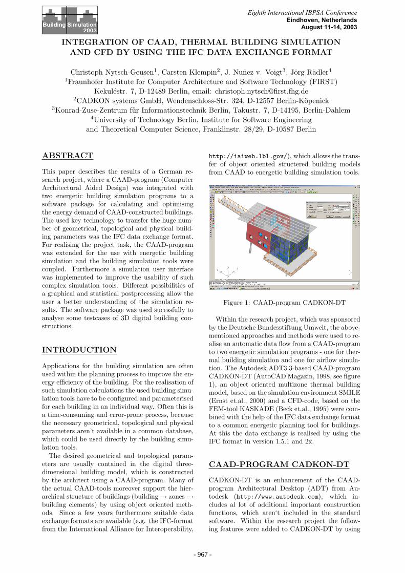
Figure 1: CAAD-program CADKON-DT
Within the research project, which was sponsoredby the Deutsche Bundesstiftung Umwelt, the above-mentioned approaches and methods were used to re-alise an automatic data flow from a CAAD-programto two energetic simulation programs - one for ther-mal building simulation and one for airflow simula-tion. The Autodesk ADT3.3-based CAAD-programCADKON-DT (AutoCAD Magazin, 1998, see figure1), an object oriented multizone thermal buildingmodel, based on the simulation environment SMILE(Ernst et.al., 2000) and a CFD-code, based on theFEM-tool KASKADE (Beck et.al., 1995) were com-bined with the help of the IFC data exchange formatto a common energetic planning tool for buildings.At this the data exchange is realised by using theIFC format in version 1.5.1 and 2x.
CAAD-PROGRAM CADKON-DT
CADKON-DT is an enhancement of the CAAD-program Architectural Desktop (ADT) from Au-todesk (http://www.autodesk.com), which in-cludes al lot of additional important constructionfunctions, which aren‘t included in the standardsoftware. Within the research project the follow-ing features were added to CADKON-DT by using
Eighth International IBPSA Conference Eindhoven, Netherlands
August 11-14, 2003
- 959 -- 967 -
the VBA/OMF API:
• Creating thermal zones: After the user has se-lected the ADT-object ’room’ he can add anumber of building element objects like walls,windows, doors, slabs and roofslabs to thisobject. Roofs and some other AEC-objectsare not supported in the current ADT3.3/IFC-interface. The room object and the build-ing element objects compose a thermal zone.Further new functions were implemented forlinking several rooms to one virtual thermalzone and for detaching building element objectsfrom zones. All connections between the ob-jects are realised with the ADT property-sets.
CADKON-DT got two new functions for vis-ible information about thermal zones and theappropriate objects. On the one hand the usercan pick an object and CADKON-DT showsthe attached zone and all other connected ob-jects. On the other hand the user can selecta thermal zone and CADKON-DT shows alllinked zones from the virtual zone, if one doesexist.
• Material database for wall layers: A materialdatabase for parameterizing different wall con-structions, realised as a simple MS-DAO 3.6database, includes material data (density, heatcapacity and heat conductivity) from Germanand European standards (DIN 4108-4 and EN12524). The user can attach values from thedatabase to the layer objects of the wall ob-ject.
• Data export by IFC 1.5.1 and 2x: At the be-ginning of the research project the ADT 3.3didn‘t support the IFC 2x format. Since au-tumn 2002 a beta version of an external devel-oped (G.E.M. Team Solutions) IFC 2x interfacecan be used in the project. Both interfaces arelimited, e.g. only a part of the properties fromthe structural members are exported and 3rdparty development isn‘t possible. This problemwas handled in CADKON-DT by an extensiveuse of the ADT property-sets.
IFC DATA TRANSFER
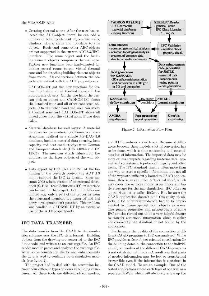
The data transfer from the CAAD to the simula-tion software uses the IFC data format. Buildingobjects from the drawing are converted to the IFCdata model and written to an exchange file. An IFCreader module parses and analyses the exchange file.After some consistency checks and enhancementsthe data is used to configure both simulation mod-els (see figure 2).
The project had to deal with the conversion be-tween four different types of views at building struc-tures. All three tools use different object models,
Figure 2: Information Flow Plan
and IFC introduces a fourth one. Because of differ-ences between these models a lot of conversion hasto be done, which is time-consuming and potenti-ates loss of information. The imported data may bemore or less complete regarding material data, geo-metrical consistency, topological integrity and otheritems. The IFC standard usually offers more thanone way to store a specific information, but not allof the ways are sufficiently bound to CAAD applica-tions. Here is an example: A ’thermal zone’, whichmay cover one or more rooms, is an important ba-sic structure for thermal simulation. IFC offers anappropriate entity called IfcZone. But because theCAAD application doesn’t bind this entity to ob-jects, a lot of workaround-code had to be imple-mented to misuse special room objects as zones.The generic properties and property-sets of someIFC entities turned out to be a very helpful featureto transfer additional information which is eithernot covered by the standard or not bound by theapplication.
Furthermore the quality of the connection of dif-ferent CAAD-programs to IFC was analysed. WhileIFC provides a clear object oriented specification forthe building domain, the connection to the individ-ual object models of the different CAAD-programsis not satisfying until today. A result was that partsof needed information may be lost or transformedirreversible even if the information is contained inthe CAAD model. To set an example: One of thetested applications stored each layer of one wall as aseparate IfcWall, which will obviously screw up the
- 960 -- 968 -
data model.An analysis and a preprocessing of the transfered
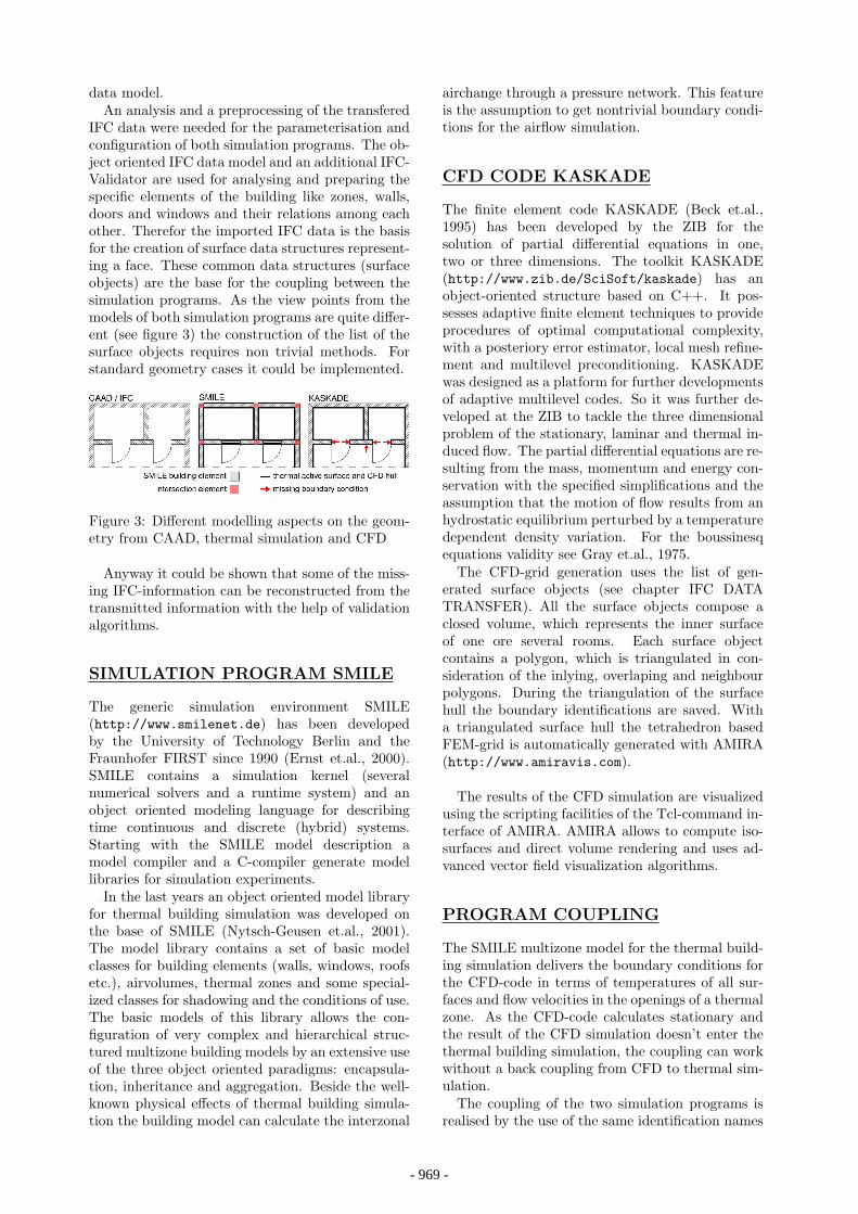
IFC data were needed for the parameterisation andconfiguration of both simulation programs. The ob-ject oriented IFC data model and an additional IFC-Validator are used for analysing and preparing thespecific elements of the building like zones, walls,doors and windows and their relations among eachother. Therefor the imported IFC data is the basisfor the creation of surface data structures represent-ing a face. These common data structures (surfaceobjects) are the base for the coupling between thesimulation programs. As the view points from themodels of both simulation programs are quite differ-ent (see figure 3) the construction of the list of thesurface objects requires non trivial methods. Forstandard geometry cases it could be implemented.
Figure 3: Different modelling aspects on the geom-etry from CAAD, thermal simulation and CFD
Anyway it could be shown that some of the miss-ing IFC-information can be reconstructed from thetransmitted information with the help of validationalgorithms.
SIMULATION PROGRAM SMILE
The generic simulation environment SMILE(http://www.smilenet.de) has been developedby the University of Technology Berlin and theFraunhofer FIRST since 1990 (Ernst et.al., 2000).SMILE contains a simulation kernel (severalnumerical solvers and a runtime system) and anobject oriented modeling language for describingtime continuous and discrete (hybrid) systems.Starting with the SMILE model description amodel compiler and a C-compiler generate modellibraries for simulation experiments.
In the last years an object oriented model libraryfor thermal building simulation was developed onthe base of SMILE (Nytsch-Geusen et.al., 2001).The model library contains a set of basic modelclasses for building elements (walls, windows, roofsetc.), airvolumes, thermal zones and some special-ized classes for shadowing and the conditions of use.The basic models of this library allows the con-figuration of very complex and hierarchical struc-tured multizone building models by an extensive useof the three object oriented paradigms: encapsula-tion, inheritance and aggregation. Beside the well-known physical effects of thermal building simula-tion the building model can calculate the interzonal
airchange through a pressure network. This featureis the assumption to get nontrivial boundary condi-tions for the airflow simulation.
CFD CODE KASKADE
The finite element code KASKADE (Beck et.al.,1995) has been developed by the ZIB for thesolution of partial differential equations in one,two or three dimensions. The toolkit KASKADE(http://www.zib.de/SciSoft/kaskade) has anobject-oriented structure based on C++. It pos-sesses adaptive finite element techniques to provideprocedures of optimal computational complexity,with a posteriory error estimator, local mesh refine-ment and multilevel preconditioning. KASKADEwas designed as a platform for further developmentsof adaptive multilevel codes. So it was further de-veloped at the ZIB to tackle the three dimensionalproblem of the stationary, laminar and thermal in-duced flow. The partial differential equations are re-sulting from the mass, momentum and energy con-servation with the specified simplifications and theassumption that the motion of flow results from anhydrostatic equilibrium perturbed by a temperaturedependent density variation. For the boussinesqequations validity see Gray et.al., 1975.
The CFD-grid generation uses the list of gen-erated surface objects (see chapter IFC DATATRANSFER). All the surface objects compose aclosed volume, which represents the inner surfaceof one ore several rooms. Each surface objectcontains a polygon, which is triangulated in con-sideration of the inlying, overlaping and neighbourpolygons. During the triangulation of the surfacehull the boundary identifications are saved. Witha triangulated surface hull the tetrahedron basedFEM-grid is automatically generated with AMIRA(http://www.amiravis.com).
The results of the CFD simulation are visualizedusing the scripting facilities of the Tcl-command in-terface of AMIRA. AMIRA allows to compute iso-surfaces and direct volume rendering and uses ad-vanced vector field visualization algorithms.
PROGRAM COUPLING
The SMILE multizone model for the thermal build-ing simulation delivers the boundary conditions forthe CFD-code in terms of temperatures of all sur-faces and flow velocities in the openings of a thermalzone. As the CFD-code calculates stationary andthe result of the CFD simulation doesn’t enter thethermal building simulation, the coupling can workwithout a back coupling from CFD to thermal sim-ulation.
The coupling of the two simulation programs isrealised by the use of the same identification names
- 961 -- 969 -
on the surfaces of the related boundary conditions.As the thermal simulation model is based on a moreabstract geometry, the CFD geometry input hasto be generated starting with the common surfaces(compare figure 3).
These common surfaces, interface between thetwo simulation programs stay invariant while thetwo simulation models are build and the FEM gridis generated. This isn’t as trivial, as it apears to be,because of the difficult task of an automated threedimensional grid generation. The SMILE programwrites the desired data (temperatures and veloci-ties) to a special file at fixed intervals. Because ofthe efficiency and ability to store and describe struc-tured information the NetCDF file format was cho-sen for that purpose. Furthermore NetCDF allowsconcurrent read and write access, which enables theairflow simulation to run before the thermal simu-lation has finished.
SIMULATION USER INTERFACE
A graphical simulation user interface allows the im-port of IFC Files, modifications and additions onthe building model, its 2D and 3D-visualization, thecontrol of the simulation experiments and a post-processing of the simulation results (figure 4).Thesimulation user interface guides the simulation en-gineer step by step through the simulation project:
Figure 4: Simulation User Interface
• Import of IFC Files: Currently it is possible toimport data files from a CAAD-program in theIFC 1.5.1 and 2x format.
• Control of the building geometry and topology:After the import of an IFC file the user cancheck the correctness of the imported buildingmodel in a different manner. On the one handhe gets the building topology (building → zones→ elements) as a tree structure. On the otherhand he can see the 2D-floor plan and a 3D-visualization of the building model if required.
• Modification and addition of building parame-ters: Normally the building parameter set com-ing from the CAAD-program by IFC is incom-plete for a building simulation. The archi-tect may have drawn the building constructionwithout wall layers. In that case the simulationuser interface sets a default value (one layerfor each wall with a standard material). Theuser can edit the wall construction by using anwall editor under the restriction of the totalwall thickness. Further on all physical buildingparameters except the building geometry andtopology may be amended within the simula-tion user interface.
• Definition of building location and weatherdata: The building model needs furthermorespecifications for the external boundary condi-tions like the building environment and orienta-tion and the building location. To this the userselects a weather data set, which was gener-ated by Meteonorm (Meteonorm, 2000) in thisproject.
• Definition of the using conditions: In the nextstep the user has to define the using condi-tions for each thermal zone. These are the settemperatures and time profiles for heating andcooling and also the time profiles for internalheating and moisture sources and ventilation.
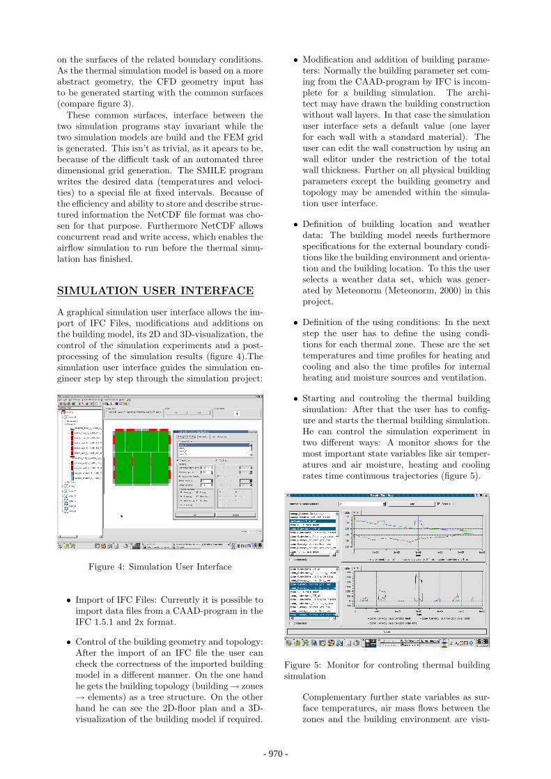
• Starting and controling the thermal buildingsimulation: After that the user has to config-ure and starts the thermal building simulation.He can control the simulation experiment intwo different ways: A monitor shows for themost important state variables like air temper-atures and air moisture, heating and coolingrates time continuous trajectories (figure 5).
Figure 5: Monitor for controling thermal buildingsimulation
Complementary further state variables as sur-face temperatures, air mass flows between thezones and the building environment are visu-
- 962 -- 970 -

alized within the 3D-building model (see theexample in the next section).
• Starting and controling the air flow simulation:After the thermal simulation has finished, theuser can choose a time point within the sim-ulated time period for the steady state CFDsimulation. The result of the CFD calculation,the three dimensional temperature and velocityfields, is visualized with the tool AMIRA.
• Postprocessing for the simulation results: Thegreat quantity of model parameter and simula-tion results is summarized by a postprocessingand is figured on a set of generated PDF-pages.These pages contain tables of input parameters,graphics of daily and monthly energy balancesand temperature and air velocity statistics andsnapshots on well-choosen planecuts for the es-timation of comfortableness.
Figure 6: Simulation results: Monthly energy bal-ances of a building
Figure 7: Simulation results: Temperature statis-tics for a single zone - outdoor temperature versusoperative room temperature
For example figure 6 shows the monthly energybalances for a building and figure 7 a temper-ature statistic for a single zone.
TESTCASES
The software package of CAAD, thermal build-ing simulation and CFD was used sucessfully inthe project for analysing simple and more complextestcases. The following example demonstrates bymeans of a building with seven thermal zones theCAAD input and possible results of the simulationtools. The simulation experiment was specified ina way that the thermal simulation program calcu-lates the energy balances and the airchange for eachsingle zone and the CFD program the temperatureand velocity fields over a region, which extends overall zones. Figure 8 shows the digital construction inCADKON-DT.
Figure 8: Digital building construction inCADKON-DT
After importing and parameterizing the buildingconstruction by the simulation user interface thethermal building simulation can be started.
Figure 9: Thermal Simulation: Inside surface tem-peratures and air mass flows between the zones andto the environment
During the simulation process or as a post-processing the 3D-visualization program SimuVis(http://www.dezentral.de/soft/SimuVis) visu-alizes the time dependend state of important build-ing model parameters, like surface temperatures,heat fluxes and air mass flows (figure 9).
- 963 -- 971 -

The results of the CFD simulation are visualizedby the program AMIRA. Figure 10 shows a hori-zontal cut trough the 3D-velocity and temperaturefield. Close to the window surfaces the air temper-atures are significant higher than the values in themiddle of the rooms. Figure 11 shows four horizon-tal cuts trough the 3D-velocity field close to a largeopening - an open door - of the building envelope.The picture illustrates the typical reversal of the airflow direction subject to the altitude.
Figure 10: Airflow simulation: Velocity and tem-perature field (horizontal cut)
Figure 11: Air flow simulation: Velocity field closeto a large opening (four horizontal cuts)
OUTLOOK
A lot of refinements and improvements have to bedone to create a working application ready for theend-user.
Despite the platform issues (ADT3.3/CADKON-DT runs on Windows, SMILE and KASKADE runs
on LINUX/UNIX) the integration of the tools hasto be enhanced.
For now only simple geometries are covered by thesoftware package, the IFC classes, which are recog-nized by the simulation tools, need to be extendedfor more complex geometries, e.g. building elementswith a curved shape or buildings with tilted roofs.
It would make sense to show a part of the simula-tion results directly in CADKON-DT for detectingthermal weakness of building elements within the3D-building construction.
The physical models for the thermal building sim-ulation and the airflow simulation should be im-proved. For example a cell model for the airvolumewithin a thermal zone would give the CFD-Codemore detailed boundary conditions. Another im-portant enhancement would be the implementationof a boundary layer model and a turbulence modelin the CFD-code. If the CFD-code would be ex-tended from a stationary to a dynamically modela back coupling from CFD to thermal simulationwould make sense.
CONCLUSIONS
• The IFC data exchange format has made it pos-sible to integrate CAAD-programs and simu-lation tools for energetic building simulation.The data flow incl. the data reconstructionfrom the CAAD-program to the simulationprograms could be implemented successfullyfor defined test cases.
• The implementation of the IFC 1.5.1 and IFC2x interface for the ADT3.3 should be stronglyimproved.
• The coupling of thermal multizone buildingsimulation program with a CFD-program forairflow simulation allows different detailed en-ergy analyses in dependence from the simula-tion question.
• The time demand for parameterizing simula-tion tools for thermal building simulation andairflow simulation could be reduced drasticallycompared to the data input and grid genera-tion by hand. It is better to have more timefor calculating variants of the building modelthan wasting the time for collecting the modelparameters.
• The simulation user interface offers an easy ac-cess and usability to both sophisticated simu-lation tools.
- 964 -- 972 -

REFERENCES
AutoCAD Magazin special 4/98, page 6, 1998
Beck, R.; Erdmann, B.; Roitzsch, R.: KASKADE3.0 - An Object-Oriented Adaptive Finite ElementCode. Technical report TR 95-4, Konrad-Zuse-Zentrum fur Informationstechnik (ZIB), Berlin,1995.
Ernst, T.; Klein-Robbenhaar, C.; Nordwig, A.;Schrag, T.: Modeling and simulation of hybridsystems with SMILE, Informatik Forschung undEntwicklung, 15:33-55, 2000.
Gray, D.D.; Giorgini, A.: The validity of theBoussinesq approximation for liquids and gases.Int. J. Heat Mass Transf. vol.19 p.545-551, 1975.
Meteonorm 4.0 - Global Meteorological databasefor Solar Energy and Applied Climatology. Me-teotest, 2000.
Nytsch-Geusen, C.; Bartsch, G.: An Object Ori-ented Multizone Thermal Building Model based onthe Simulation Enviroment SMILE. in: Proceedingsof Building Simulation 2001, International Build-ing Performance Simulation Association, Rio deJaneiro, 2001.
- 965 -- 973 -

- 966 -- 974 -