Embed Size (px)
Citation preview
NREL is a national laboratory of the U.S. Department of Energy, Office of Energy Efficiency and Renewable Energy, operated by the Alliance for Sustainable Energy, LLC.
Integrated Vehicle Thermal Management – Combining Fluid Loops in Electric Drive Vehicles
John P. Rugh National Renewable Energy Laboratory May 15, 2013
Project ID: APE052
This presentation does not contain any proprietary, confidential, or otherwise restricted information.
2
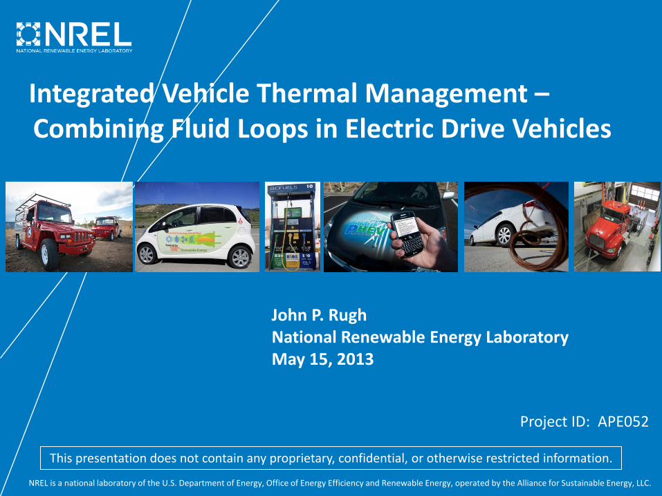
Overview
Project Start Date: FY11 Project End Date: FY14 Percent Complete: 50%
• Cost – cooling loop components • Life – thermal effects on energy
storage system (ESS) and advanced power electronics and electric motors (APEEM)
• Weight – additional cooling loops in electric drive vehicles (EDVs)
Total Project Funding (to date): $ 1225 K * Funding received prior to FY13: $ 750 K * Funding for FY13: $ 475 K * Partner In-Kind Cost Share: $ 300 K **
Timeline
Budget
Barriers (to EDVs)
• Interactions/ collaborations – Delphi – Halla Visteon Climate Control – Magna Powertrain - Engineering
Center Steyr – Ford
• Project Lead – National Renewable Energy
Laboratory
Partners
* Shared funding between VTO programs: VSST, APEEM, ESS ** Not included in total
3
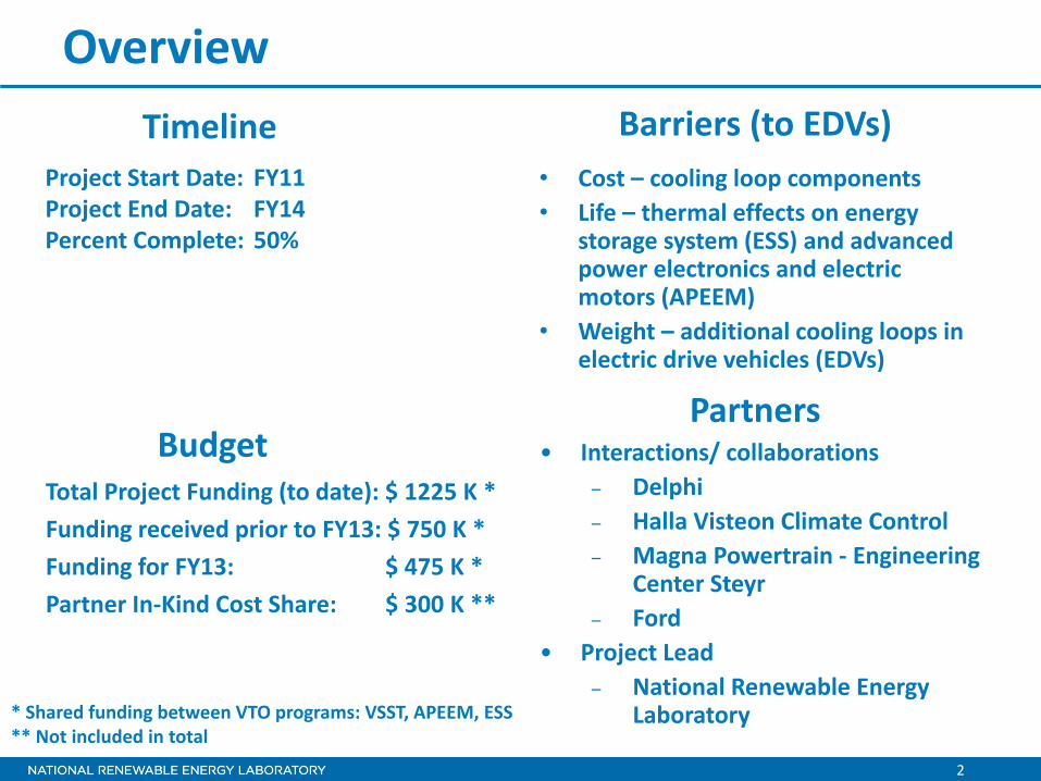
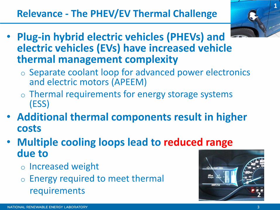
Relevance - The PHEV/EV Thermal Challenge
• Plug-in hybrid electric vehicles (PHEVs) and electric vehicles (EVs) have increased vehicle thermal management complexity o Separate coolant loop for advanced power electronics
and electric motors (APEEM) o Thermal requirements for energy storage systems
(ESS) • Additional thermal components result in higher
costs • Multiple cooling loops lead to reduced range
due to o Increased weight o Energy required to meet thermal requirements
1
2
4
Relevance
• Support broad VTO efforts o DOE VTO MYPP
– “…..development of advanced vehicles and components to maximize vehicle efficiency …..”
– This projects seeks to maximize vehicle efficiency by developing combined cooling loop solutions to reduce parasitic power, improved battery temperature, and increase range.
o President’s EV-Everywhere Grand Challenge – A goal of EV Everywhere is to have automobile manufacturers produce a car
with sufficient range that meets consumer’s daily transportation needs. – This project is researching techniques to reduce vehicle thermal management
power and improve range. • Task Objective
o Collaborate with industry partners to research the synergistic benefits of combining thermal management systems in vehicles with electric powertrains
o Solve vehicle-level heat transfer problems, which will enable acceptance of electric drive vehicles
5
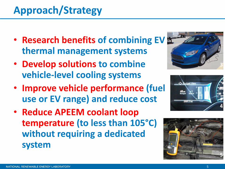
Approach/Strategy
• Research benefits of combining EV thermal management systems
• Develop solutions to combine vehicle-level cooling systems
• Improve vehicle performance (fuel use or EV range) and reduce cost
• Reduce APEEM coolant loop temperature (to less than 105°C) without requiring a dedicated system
3
4
5
6
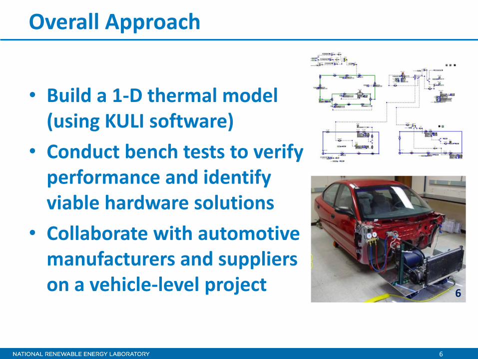
Overall Approach
• Build a 1-D thermal model (using KULI software)
• Conduct bench tests to verify performance and identify viable hardware solutions
• Collaborate with automotive manufacturers and suppliers on a vehicle-level project
6
7
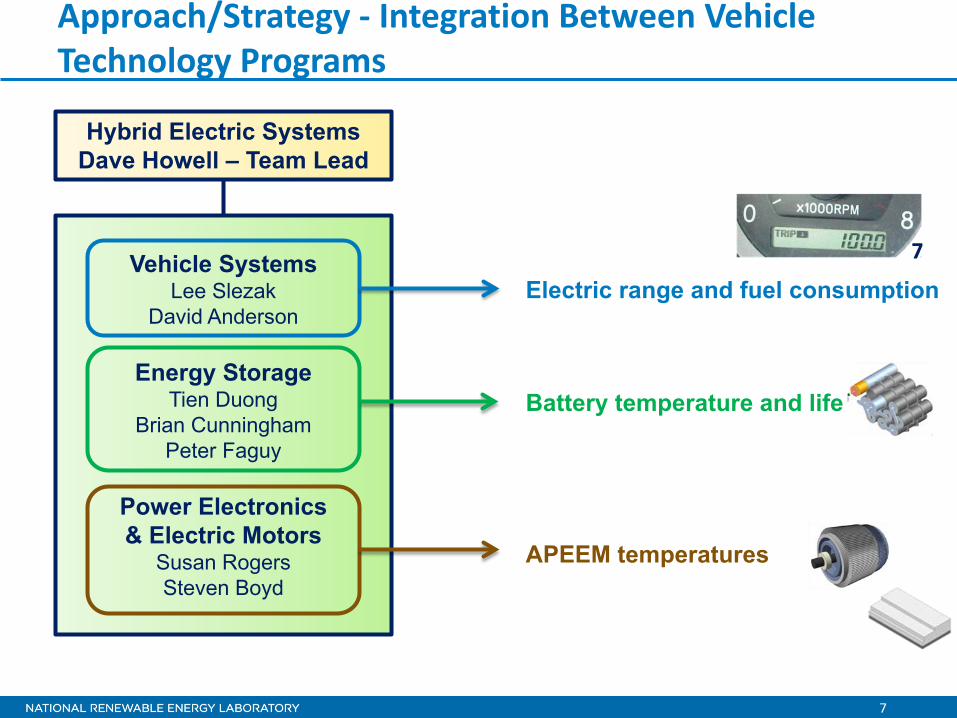
Vehicle Systems
Lee Slezak David Anderson
Energy Storage
Tien Duong Brian Cunningham
Peter Faguy
Power Electronics & Electric Motors
Susan Rogers Steven Boyd
Approach/Strategy - Integration Between Vehicle Technology Programs
Hybrid Electric Systems Dave Howell – Team Lead
Electric range and fuel consumption
APEEM temperatures
Battery temperature and life
7
8
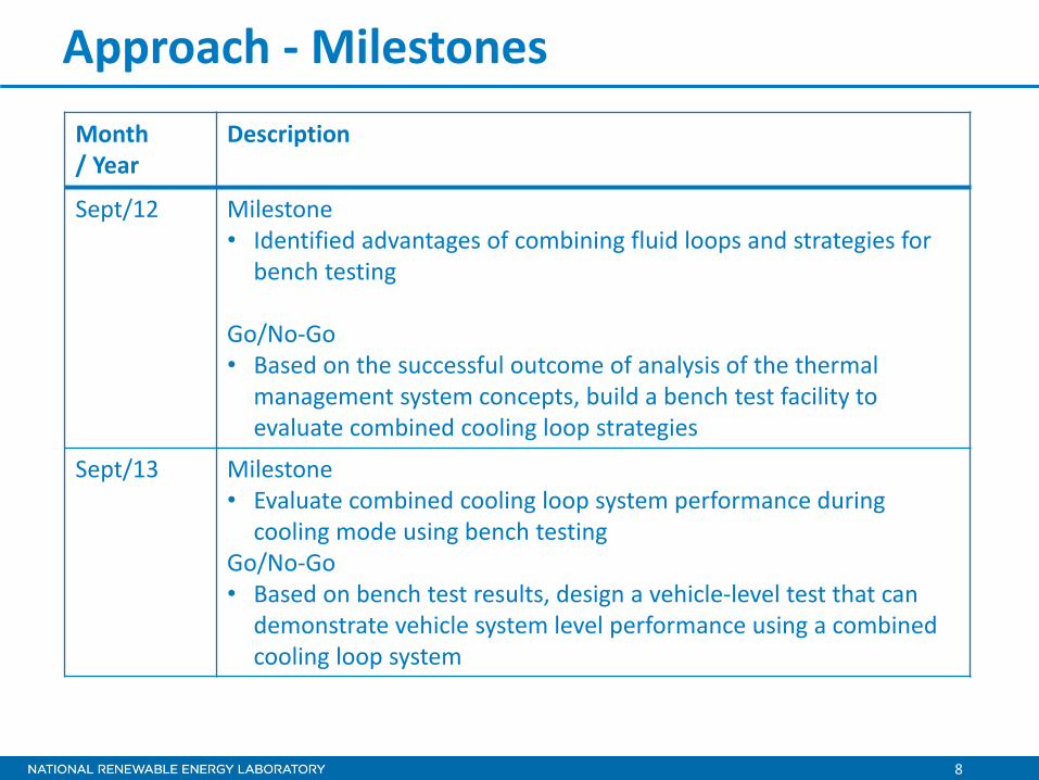
Approach - Milestones Month / Year
Description
Sept/12 Milestone • Identified advantages of combining fluid loops and strategies for
bench testing Go/No-Go • Based on the successful outcome of analysis of the thermal
management system concepts, build a bench test facility to evaluate combined cooling loop strategies
Sept/13 Milestone • Evaluate combined cooling loop system performance during
cooling mode using bench testing Go/No-Go • Based on bench test results, design a vehicle-level test that can
demonstrate vehicle system level performance using a combined cooling loop system
9
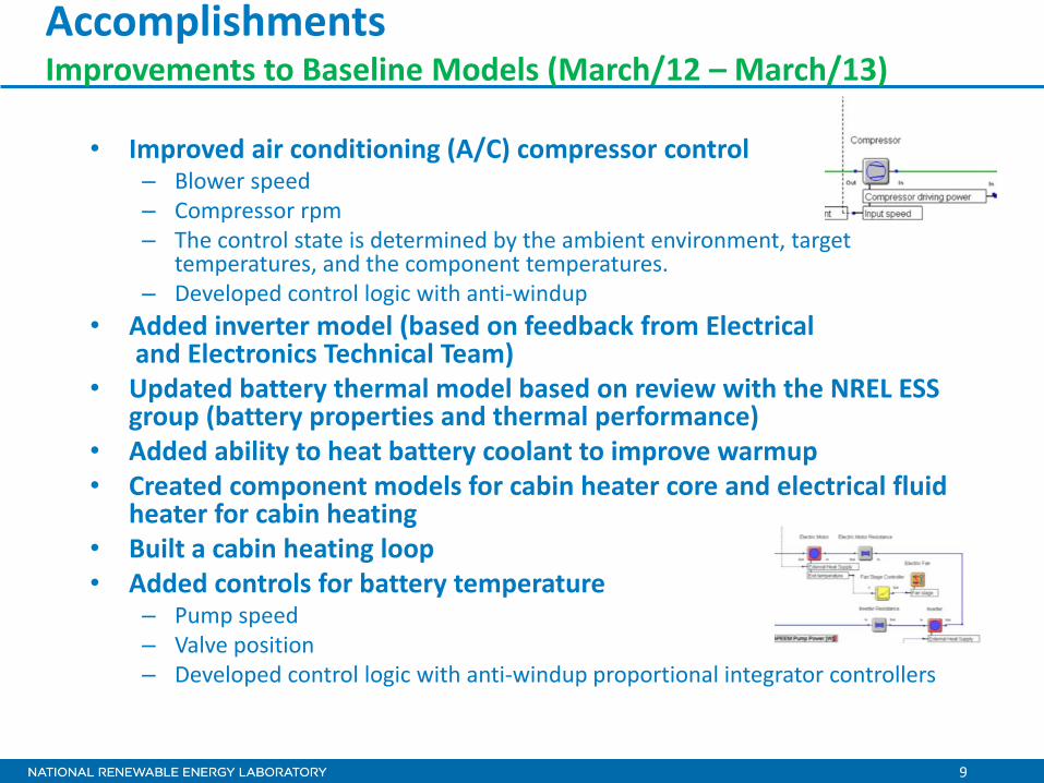
• Improved air conditioning (A/C) compressor control – Blower speed – Compressor rpm – The control state is determined by the ambient environment, target
temperatures, and the component temperatures. – Developed control logic with anti-windup
• Added inverter model (based on feedback from Electrical and Electronics Technical Team)
• Updated battery thermal model based on review with the NREL ESS group (battery properties and thermal performance)
• Added ability to heat battery coolant to improve warmup • Created component models for cabin heater core and electrical fluid
heater for cabin heating • Built a cabin heating loop • Added controls for battery temperature
– Pump speed – Valve position – Developed control logic with anti-windup proportional integrator controllers
Accomplishments Improvements to Baseline Models (March/12 – March/13)
10
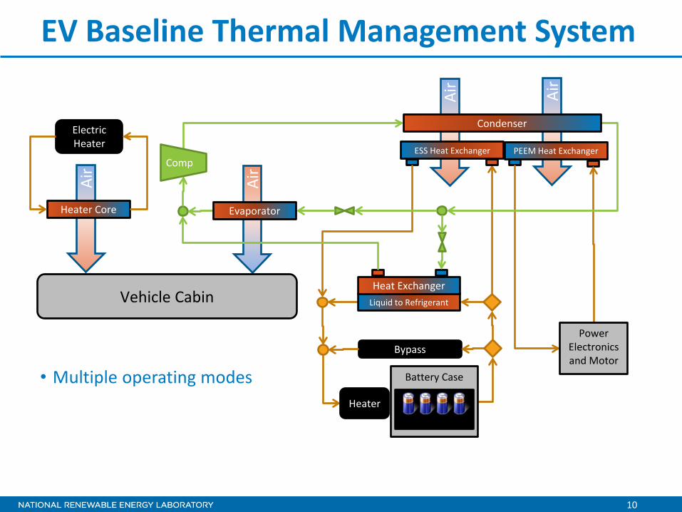
EV Baseline Thermal Management System Ai
r
Air
Air
Air
Bypass
ESS Heat Exchanger
Vehicle Cabin
PEEM Heat Exchanger
Liquid to Refrigerant
Heat Exchanger
Battery Case
Cells
Evaporator
Power Electronics and Motor
Condenser
Heater
Electric Heater
Heater Core
Comp
• Multiple operating modes
11
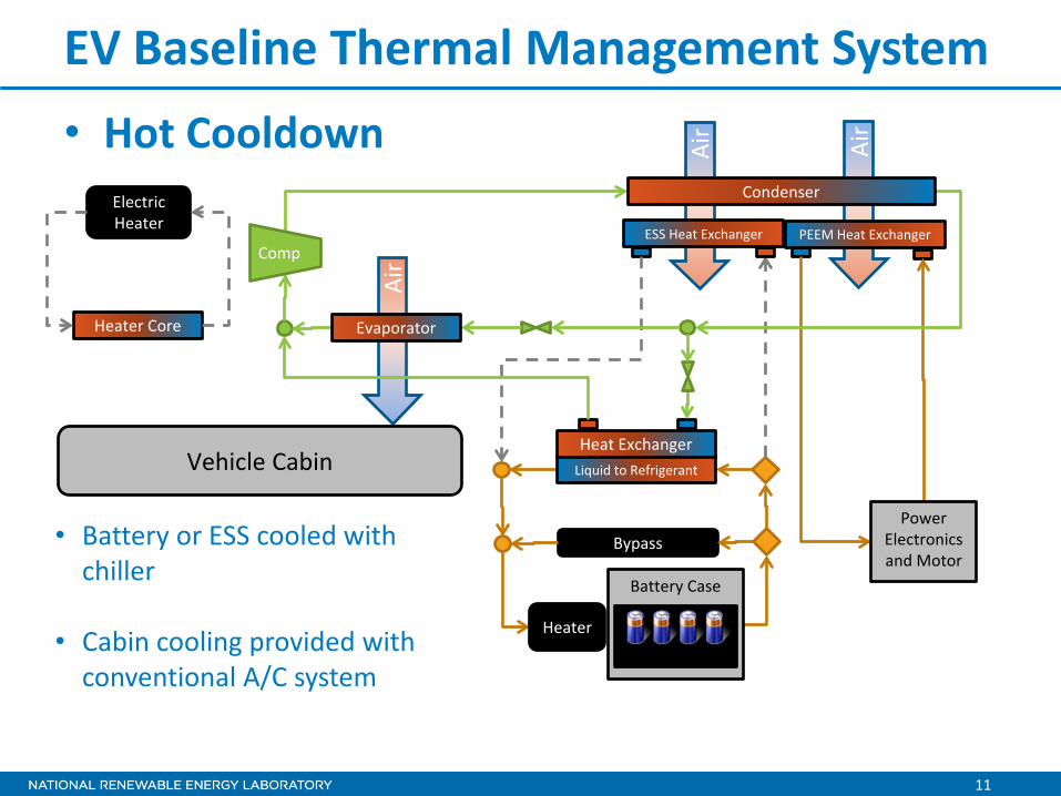
EV Baseline Thermal Management System • Hot Cooldown Ai
r
Air
Air
Bypass
ESS Heat Exchanger PEEM Heat Exchanger
Liquid to Refrigerant
Heat Exchanger
Battery Case
Cells
Evaporator
Power Electronics and Motor
Condenser
Heater
Electric Heater
Heater Core
Comp
Vehicle Cabin
• Battery or ESS cooled with chiller
• Cabin cooling provided with conventional A/C system
12
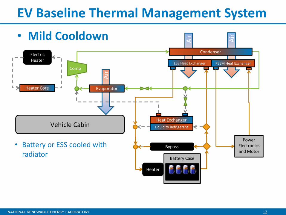
EV Baseline Thermal Management System • Mild Cooldown Ai
r
Air
Air
Bypass
ESS Heat Exchanger PEEM Heat Exchanger
Liquid to Refrigerant
Heat Exchanger
Battery Case
Cells
Evaporator
Power Electronics and Motor
Condenser
Heater
Electric Heater
Heater Core
Comp
Vehicle Cabin
• Battery or ESS cooled with radiator
13
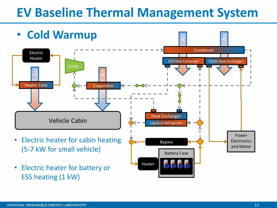
EV Baseline Thermal Management System Ai
r
Air
Air
Air
Bypass
ESS Heat Exchanger PEEM Heat Exchanger
Liquid to Refrigerant
Heat Exchanger
Battery Case
Cells
Evaporator
Power Electronics and Motor
Condenser
Heater
Electric Heater
Heater Core
Comp
• Cold Warmup
Vehicle Cabin
• Electric heater for cabin heating (5-7 kW for small vehicle)
• Electric heater for battery or ESS heating (1 kW)
14
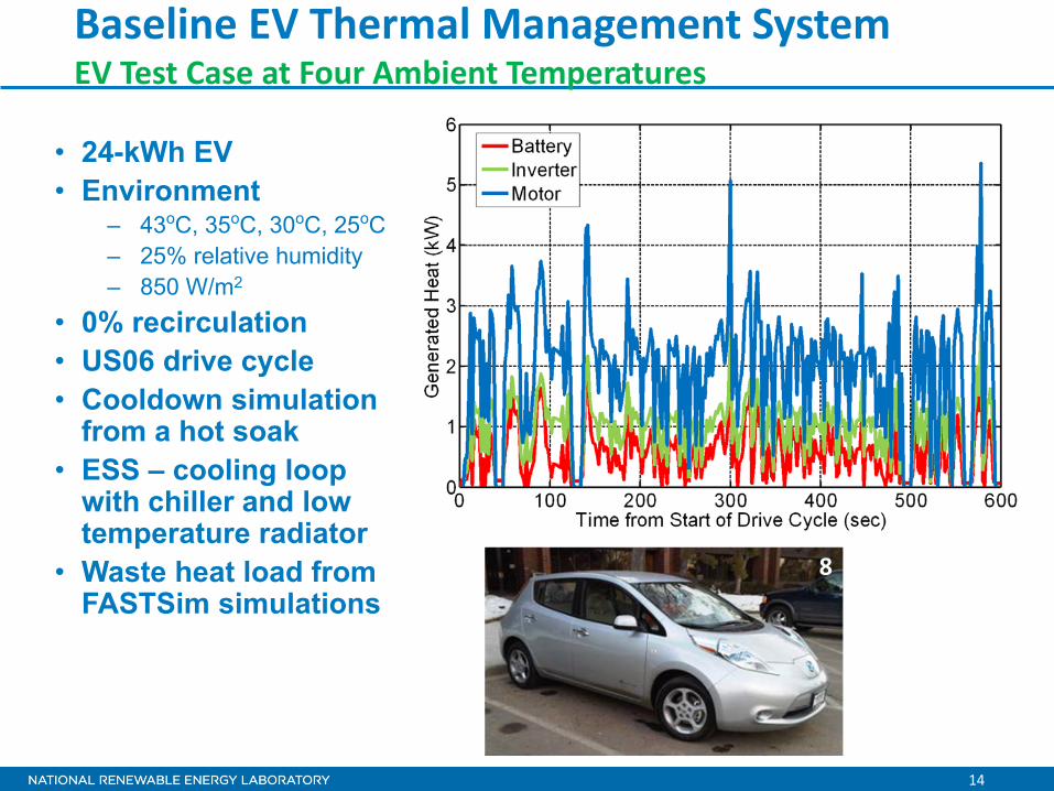
• 24-kWh EV • Environment
– 43oC, 35oC, 30oC, 25oC – 25% relative humidity – 850 W/m2
• 0% recirculation • US06 drive cycle • Cooldown simulation
from a hot soak • ESS – cooling loop
with chiller and low temperature radiator
• Waste heat load from FASTSim simulations
Baseline EV Thermal Management System EV Test Case at Four Ambient Temperatures
8
15
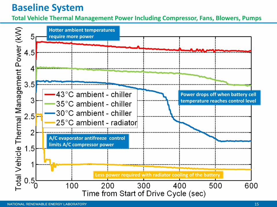
Baseline System Total Vehicle Thermal Management Power Including Compressor, Fans, Blowers, Pumps
Power drops off when battery cell temperature reaches control level
Hotter ambient temperatures require more power
Less power required with radiator cooling of the battery
A/C evaporator antifreeze control limits A/C compressor power
16
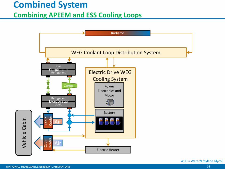
Combined System Combining APEEM and ESS Cooling Loops
Electric Drive WEG Cooling System
Air
Air
Vehi
cle
Cabi
n
Cabi
n Co
oler
Power Electronics and
Motor
Radiator
Liquid
Refrigerant Condenser
Refrigerant
Liquid Evaporator
Comp
WEG Coolant Loop Distribution System
Battery
Cells
Cabi
n He
ater
Electric Heater
WEG = Water/Ethylene Glycol
17
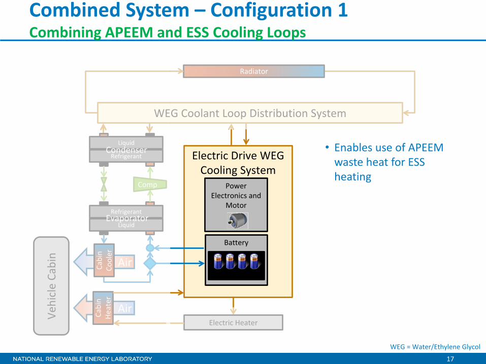
Combined System – Configuration 1 Combining APEEM and ESS Cooling Loops
Electric Drive WEG Cooling System
Air
Air
Vehi
cle
Cabi
n
Cabi
n Co
oler
Power Electronics and
Motor
Radiator
Liquid
Refrigerant Condenser
Refrigerant
Liquid Evaporator
Comp
WEG Coolant Loop Distribution System
Battery
Cells
Cabi
n He
ater
Electric Heater
• Enables use of APEEM waste heat for ESS heating
WEG = Water/Ethylene Glycol
18
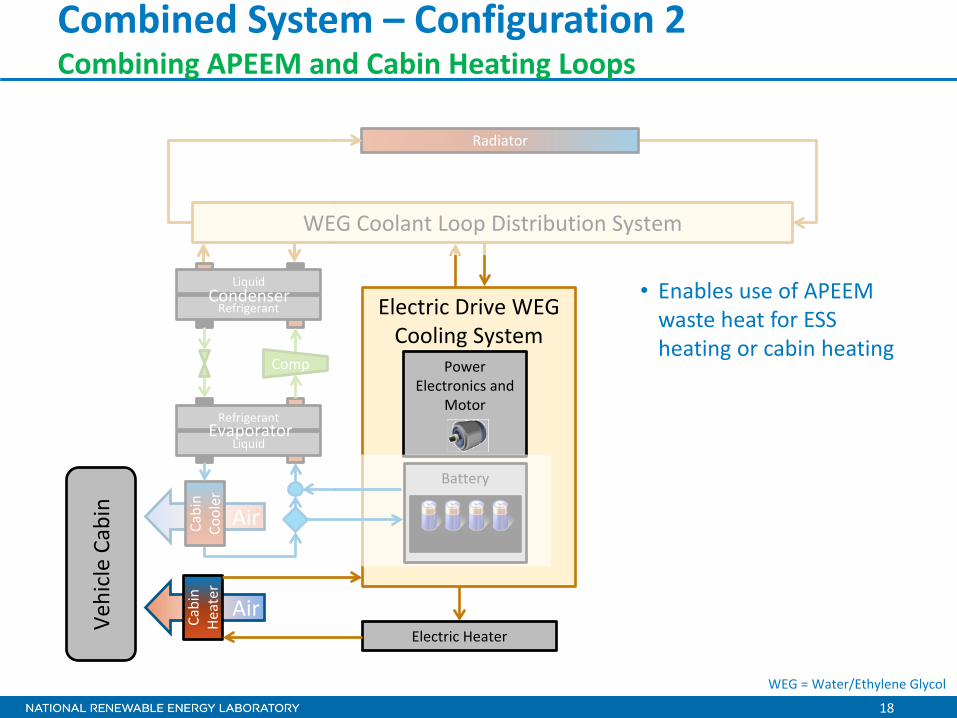
Combined System – Configuration 2 Combining APEEM and Cabin Heating Loops
Electric Drive WEG Cooling System
Air
Air
Vehi
cle
Cabi
n
Cabi
n Co
oler
Power Electronics and
Motor
Radiator
Liquid
Refrigerant Condenser
Refrigerant
Liquid Evaporator
Comp
WEG Coolant Loop Distribution System
Battery
Cells
Cabi
n He
ater
Electric Heater
• Enables use of APEEM waste heat for ESS heating or cabin heating
WEG = Water/Ethylene Glycol
19
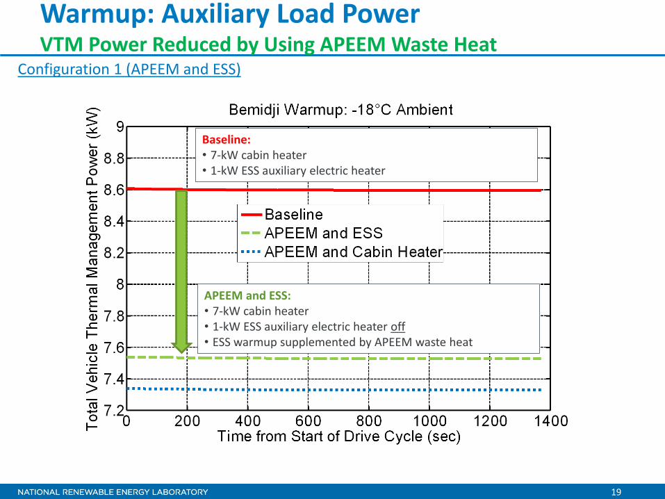
Warmup: Auxiliary Load Power VTM Power Reduced by Using APEEM Waste Heat
Baseline: • 7-kW cabin heater • 1-kW ESS auxiliary electric heater
APEEM and ESS: • 7-kW cabin heater • 1-kW ESS auxiliary electric heater off • ESS warmup supplemented by APEEM waste heat
Configuration 1 (APEEM and ESS)
20
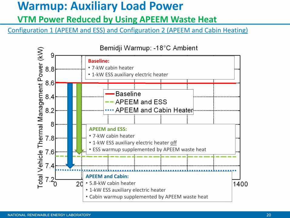
Warmup: Auxiliary Load Power VTM Power Reduced by Using APEEM Waste Heat
Baseline: • 7-kW cabin heater • 1-kW ESS auxiliary electric heater
APEEM and Cabin: • 5.8-kW cabin heater • 1-kW ESS auxiliary electric heater • Cabin warmup supplemented by APEEM waste heat
APEEM and ESS: • 7-kW cabin heater • 1-kW ESS auxiliary electric heater off • ESS warmup supplemented by APEEM waste heat
Configuration 1 (APEEM and ESS) and Configuration 2 (APEEM and Cabin Heating)
21
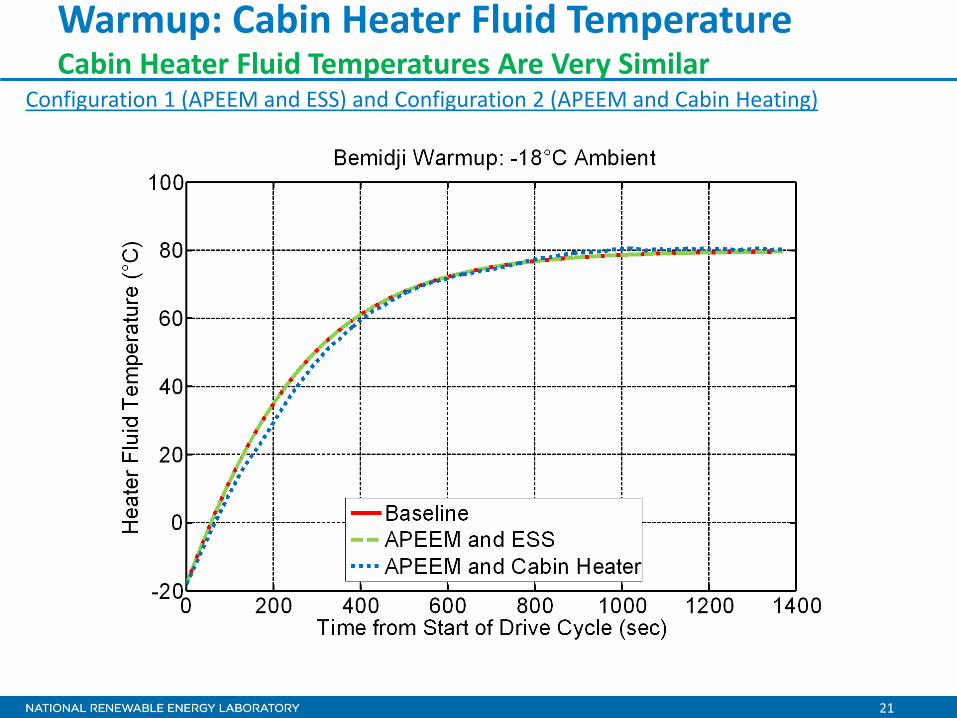
Warmup: Cabin Heater Fluid Temperature Cabin Heater Fluid Temperatures Are Very Similar
Configuration 1 (APEEM and ESS) and Configuration 2 (APEEM and Cabin Heating)
22
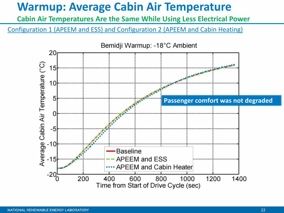
Warmup: Average Cabin Air Temperature Cabin Air Temperatures Are the Same While Using Less Electrical Power
Passenger comfort was not degraded
Configuration 1 (APEEM and ESS) and Configuration 2 (APEEM and Cabin Heating)
23
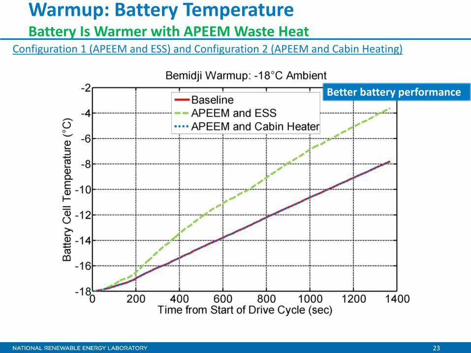
Warmup: Battery Temperature Battery Is Warmer with APEEM Waste Heat
Better battery performance
Configuration 1 (APEEM and ESS) and Configuration 2 (APEEM and Cabin Heating)
24
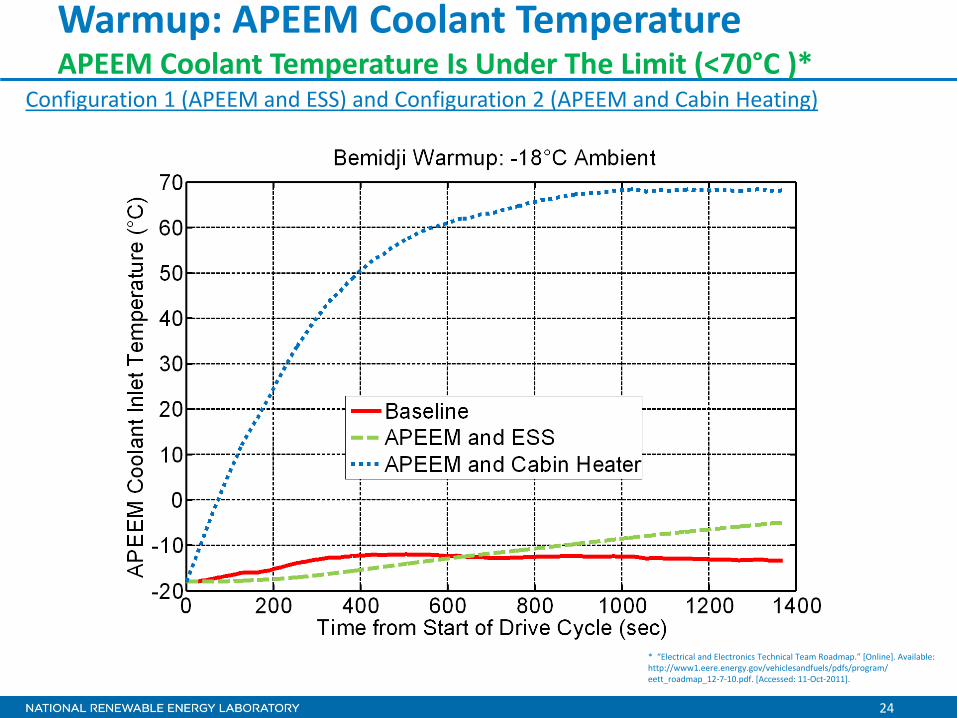
Warmup: APEEM Coolant Temperature APEEM Coolant Temperature Is Under The Limit (<70°C )*
* “Electrical and Electronics Technical Team Roadmap.” [Online]. Available: http://www1.eere.energy.gov/vehiclesandfuels/pdfs/program/ eett_roadmap_12-7-10.pdf. [Accessed: 11-Oct-2011].
Configuration 1 (APEEM and ESS) and Configuration 2 (APEEM and Cabin Heating)
25
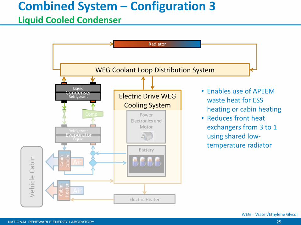
Combined System – Configuration 3 Liquid Cooled Condenser
Electric Drive WEG Cooling System
Air
Air
Vehi
cle
Cabi
n
Cabi
n Co
oler
Power Electronics and
Motor
Radiator
Liquid
Refrigerant Condenser
Refrigerant
Liquid Evaporator
Comp
WEG Coolant Loop Distribution System
Battery
Cells
Cabi
n He
ater
Electric Heater
• Enables use of APEEM waste heat for ESS heating or cabin heating
• Reduces front heat exchangers from 3 to 1 using shared low-temperature radiator
WEG = Water/Ethylene Glycol
26
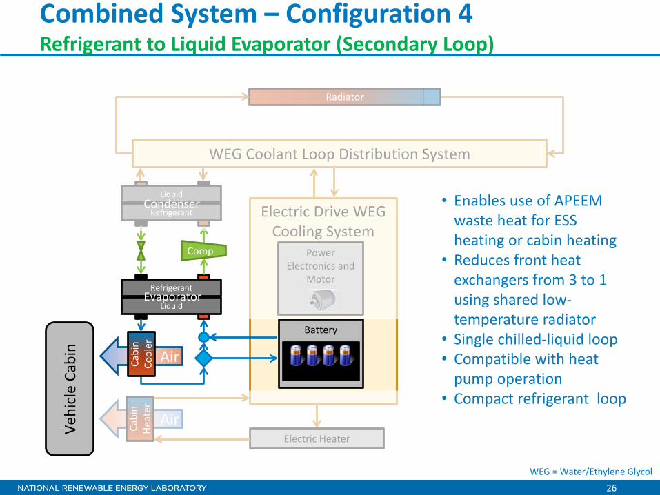
Combined System – Configuration 4 Refrigerant to Liquid Evaporator (Secondary Loop)
Electric Drive WEG Cooling System
Air
Air
Vehi
cle
Cabi
n
Cabi
n Co
oler
Power Electronics and
Motor
Radiator
Liquid
Refrigerant Condenser
Refrigerant
Liquid Evaporator
Comp
WEG Coolant Loop Distribution System
Battery
Cells
Cabi
n He
ater
Electric Heater
• Enables use of APEEM waste heat for ESS heating or cabin heating
• Reduces front heat exchangers from 3 to 1 using shared low-temperature radiator
• Single chilled-liquid loop • Compatible with heat
pump operation • Compact refrigerant loop
WEG = Water/Ethylene Glycol
27
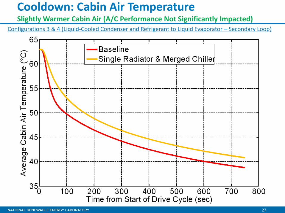
Cooldown: Cabin Air Temperature Slightly Warmer Cabin Air (A/C Performance Not Significantly Impacted)
Configurations 3 & 4 (Liquid-Cooled Condenser and Refrigerant to Liquid Evaporator – Secondary Loop)
28
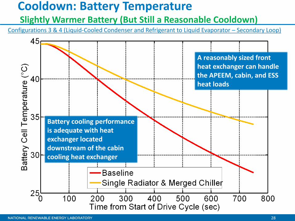
Cooldown: Battery Temperature Slightly Warmer Battery (But Still a Reasonable Cooldown)
A reasonably sized front heat exchanger can handle the APEEM, cabin, and ESS heat loads
Configurations 3 & 4 (Liquid-Cooled Condenser and Refrigerant to Liquid Evaporator – Secondary Loop)
Battery cooling performance is adequate with heat exchanger located downstream of the cabin cooling heat exchanger
29
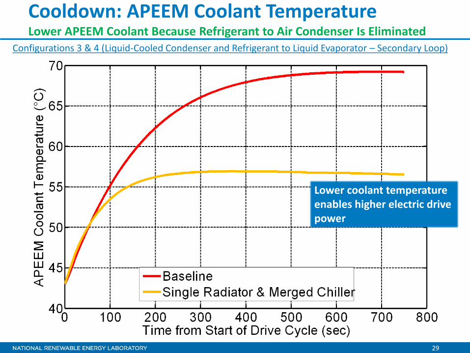
Cooldown: APEEM Coolant Temperature Lower APEEM Coolant Because Refrigerant to Air Condenser Is Eliminated
Configurations 3 & 4 (Liquid-Cooled Condenser and Refrigerant to Liquid Evaporator – Secondary Loop)
Lower coolant temperature enables higher electric drive power
30
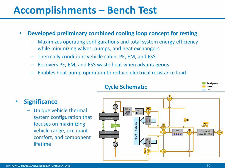
• Developed preliminary combined cooling loop concept for testing – Maximizes operating configurations and total system energy efficiency
while minimizing valves, pumps, and heat exchangers – Thermally conditions vehicle cabin, PE, EM, and ESS – Recovers PE, EM, and ESS waste heat when advantageous – Enables heat pump operation to reduce electrical resistance load
Accomplishments – Bench Test
• Significance – Unique vehicle thermal
system configuration that focuses on maximizing vehicle range, occupant comfort, and component lifetime
31
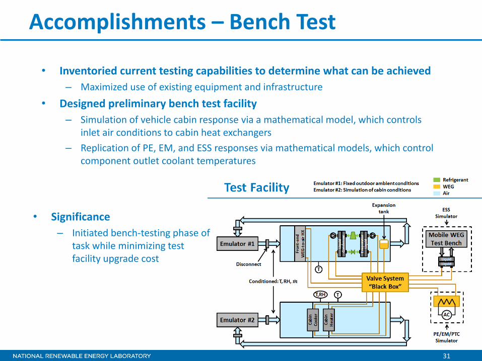
• Inventoried current testing capabilities to determine what can be achieved – Maximized use of existing equipment and infrastructure
• Designed preliminary bench test facility – Simulation of vehicle cabin response via a mathematical model, which controls
inlet air conditions to cabin heat exchangers – Replication of PE, EM, and ESS responses via mathematical models, which control
component outlet coolant temperatures
Accomplishments – Bench Test
• Significance – Initiated bench-testing phase of
task while minimizing test facility upgrade cost
32
• Delphi • Halla Visteon Climate Control
– Data – Engineering support
• Magna Powertrain – Engineering Center Steyr – KULI software – Engineering support
• Ford – Electric Focus (loaned to NREL for the Electric Drive Vehicle
Climate Control Load Reduction Task) • VTO Tasks
– Advanced Power Electronics and Electric Motors – Vehicle Systems – Energy Storage
Collaboration and Coordination with Other Institutions
33
• Remainder of FY13 – Finalize combined cooling loop design in conjunction with industry
o Coordinate with Delphi and Visteon on configuration and components – Construct bench testing facility – Conduct bench testing to evaluate combined cooling loop system
performance during cooling mode – Validate previously built KULI models of combined cooling loop
• FY14 – Utilize existing bench testing facility and experimental system to
conduct heating mode testing – Work with industry partners to design a vehicle-level test that can
demonstrate vehicle system level performance when using a combined cooling loop system
– Install experimental system and measurement equipment in a test EDV
– Experimentally evaluate EDV performance to demonstrate the effect that the combined cooling loop has on electric vehicle range
Proposed Future Work
34
• DOE Mission Support – Combining cooling systems in EDVs may reduce costs and improve
performance, which would accelerate consumer acceptance, increase EDV usage, and reduce petroleum consumption.
• Overall Approach – Build a thermal 1-D model (using KULI software)
o APEEM, energy storage, engine, transmission, and passenger compartment thermal management systems
o Identify the synergistic benefits from combining the systems – Select the most promising combined thermal management
system concepts and perform a detailed performance assessment and bench top tests
– Collaborate with automotive manufacturers and suppliers on a vehicle-level project
– Solve vehicle-level heat transfer problems, which will enable acceptance of vehicles with electric powertrains
Summary
35
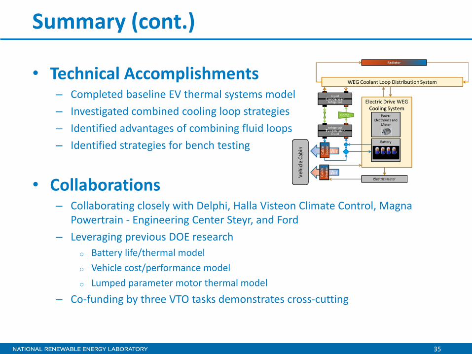
• Technical Accomplishments – Completed baseline EV thermal systems model – Investigated combined cooling loop strategies – Identified advantages of combining fluid loops – Identified strategies for bench testing
• Collaborations – Collaborating closely with Delphi, Halla Visteon Climate Control, Magna
Powertrain - Engineering Center Steyr, and Ford – Leveraging previous DOE research
o Battery life/thermal model o Vehicle cost/performance model o Lumped parameter motor thermal model
– Co-funding by three VTO tasks demonstrates cross-cutting
Summary (cont.)
For more information, contact:
Principal Investigator John Rugh [email protected] Phone: (303)-275-4413 APEEM Task Leader:
Sreekant Narumanchi [email protected] Phone: (303)-275-4062
Acknowledgments:
David Anderson Steven Boyd Brian Cunningham David Howell Susan Rogers Lee Slezak Vehicle Technologies Office U.S. Department of Energy Team Members:
Kevin Bennion Daniel Leighton Jeff Tomerlin
37
Photo Credits
1. Matt Jeffers, NREL 2. John Rugh, NREL 3. Matt Jeffers, NREL 4. John Rugh, NREL 5. Michelle Rugh, Amateur Photographer 6. Charlie King, NREL 7. John Rugh, NREL 8. John Rugh, NREL