Embed Size (px)
Citation preview
Environmental Engineering and Management Journal November 2013, Vol.12, No. S11, Supplement, 253-256
http://omicron.ch.tuiasi.ro/EEMJ/
“Gheorghe Asachi” Technical University of Iasi, Romania
INTEGRATED TECHNOLOGIES FOR SEDIMENT TREATMENT
Extended abstract
Augusto Bianchini1, Marco Pellegrini1, Giovanni Preda2, Cesare Saccani1, Daniele Vanni2
1University of Bologna, Department of Industrial Engineering (DIN), Viale Risorgimento 2, 40136, Bologna, Italy 2Design Research and Development Centre, Trevi SpA, Via Dismano 5819, 47023, Cesena, Italy
Background
The management of sediment in aquatic ecosystem has been an important issue for water managers throughout history. The changing nature of sediment issues, due to increasing human populations, the increasing prevalence of man and recognition of the important role of sediment in the transport and fate of contaminants has meant that sediment management today faces many complex technical and environmental challenges. Sediment management is complex, involving a careful balance of science, policy and economics. So, there is not a single correct way to address a problem, but, rather, the approach should be driven by the ecological, political and economic goals of interested parties.
When sediments are managed to achieve ecological goals (i.e. reclamation of the seabed next to former industrial areas), the main focus is on sediment contamination analysis, removal and treatment or disposal, thus involving sediment quality more than quantity. Trevi SpA, together with the Department of Industrial Engineering (DIN) of Bologna University designed, realized and tested a new dredging prototypal device, called Sludge Buster (SB), that has been designed for application where excavation accuracy and environmental impact minimization have particular relevance (i.e. contaminated sites).
On the other hand, when sediments are managed to achieve socioeconomic goals (like navigational dredging or flood defense), the focus is on managing sediment quantity, because it is the presence or absence of sediment that is affecting final objective (for example, excess sediments in navigation channels) However, uncontaminated sediments have some ecosystems implications in terms of turbidity and/or habitat loss. In these cases, the movement of sediments is a given (if permitted), involving also management of removal, placement, disposal and/or treatment options. Trevi SpA, together with DIN designed, realized and a first commissioned a prototypal Pneumatic Flow Mixing (PFM) method plant. PFM method is a process for sediments transport and on-line consolidation (Oota et al., 2009). Objectives
Sediment removal activities carried out with usual machineries (such as mechanical or hydraulic dredges) generate significant problems, especially in contaminated sites, due to the mechanical and/or hydraulic action of the dredge which involves the re-suspension of a considerable part of the dredged material. Moreover, the action of such devices does not allow to reach high performance in terms of precision dredging. Finally, also the working depth range is limited. Therefore, design specifications for an innovative technology for dredging of sediments, particularly those contaminated, should be (1) no moving submarine mechanical devices, (2) minimization of turbidity generated by the dredging device, (3) high accuracy in sediment removal and (4) adaptability to different depths (operational flexibility). SB was developed to reach these objectives. A first prototype was tested to verify its functional characteristics.
A new approach is needed to optimize sediment management after dredging, in particular regarding to sediment transport, which is often seen as a separated phase of the sediment reuse cycle. Instead of moving the dredged material and storing it for an indefinite time waiting for the follow-up treatments, you can think of to take advantage from this movement to perform some additional treatment on the sediment. PFM method was developed Author to whom all correspondence should be addressed: e-mail: [email protected]
Bianchini et al./Environmental Engineering and Management Journal 12 (2013), S11, Supplement, 253-256
254
to allow sediment transport and on-line stabilization by injection of binder trough transport line. A first prototype plant was designed by use of software simulator.
Outline of the work This work is divided in two main parts: The first part covers design process and experimental test results on first SB prototype. Based on results, a new
industrial prototype was designed and realized. The second part covers design process of PFM prototypal plant. In particular, the paper shows critical aspects in
PFM plant design. Methods
A jet pump is a device that transfers momentum from a high velocity primary jet flow to a secondary flow. It is geometrically simple since it consists of four main components: nozzle, suction chamber, mixing throat and diffuser. The absence of moving mechanical parts eliminates operational problems associated with bearings, seals and lubrication. Moreover, when applied in sediment removal from backdrop, turbidity and, generally, environmental impact are minimized. Jet pump has been used in the field of sediment management since ‘70 (McNair, 1976), especially for sand by-passing plant. DIN developed an innovative plant for draught maintain characterized by the fact that the main element, called “ejector”, is a fixed open jet pump (i.e. without closed suction chamber and mixing throat) with a converging instead of a diffuser. First experimental plant was designed, realized and tested (Amati and Saccani, 2005) in Riccione, Italy, showing good results in terms of efficiency and economic. A second industrial scaled up and fully automatized plant has been installed in Portoverde, Italy, and is still under experimental investigation regarding management costs that, however, seems to be an order of magnitude lower than dredge ones. Since the fixed ejectors plant demonstrates to reach the goals (1) and (2), Trevi and DIN decided to adapt this technology to a mobile device, which is the SB.
PFM can be classified as a premixing treatment method where dredged sediment and binder are carried out in a transfer or discharge pipeline (Oota et al., 2009). The materials in the pipeline are mixed by the effect of turbulent flow caused by pneumatic conveying transport conditions. In the PFM method dredged sediment is discharged on a screening and then in a hopper, where water can be added. The sediment is pumped into the transport pipeline until compressed air is injected. Pneumatic conveying is designed to obtain a plug flow transport: plug flow increases turbulence, thus allowing mixing between sediment and binder, that is usually cement. Depending on plant size, about 50-100 m are needed to fully develop plug flow into the pipeline. So, cement injection is placed at a distance L1 from air injection. A minimum length L2 before treated sediment discharge from pipeline is needed too, in order to guarantee cement and sediment mixing. Plug flow has also the skill of reducing pressure loss into the pipeline if compared with sediment transport at full pipe with the same velocity (about 8-10 m/s), that is the parameter that affects transport mixing capacity. Pneumatic conveying design is a central issue in PFM design process. Over the years DIN developed a fluid-dynamic software simulator, called TPSimWin, able to foresee pneumatic conveying parameters that produce a certain transport behavior (Saccani, 2005). TPSimWin has been used in PFM prototype plant design process. Moreover, sediment density control is an important issue in PFM method. Sediment density must be controlled to keep constant as possible the mass ratio w/c between sediment water content w and cement c, since this parameter affects sediment strength and treatment cost. Results and discussion
An SB prototype has been designed in 2008, then realized and tested in 2009. First experimental campaign was conducted with the final aim of optimize hydraulic section and to determine SB behavior as a function of different geometrical parameters, that are nozzle diameter d and distance L between nozzle output and converging inlet.
Both delivery flow and mixture ratio (that is the mass ratio between solid and water inside the discharged mixture) were estimated on the basis of previous experience (Amati and Saccani, 2005). So, D was chosen to guarantee an output SB velocity higher than saltation velocity, thus avoiding discharge clogging.
Since D is a fixed parameter, dimensionless geometrical parameters d’ and L’ were defined as d’=d/D and L’=L/D. SB was tested on a drainage canal: sediment composition was about 80-85% of silt and clay and about 12-14% of sand. SB was trained by a boat which was connected to a winch, located at the shore. Boat (and thus SB) velocity may be regulated on five level, from about 6 to 29 cm/s. Test were carried on both in static condition (motionless SB placed on the riverbed) and in dynamic condition (boat and SB trained by the winch).
Pressure of primary flow was measured at the nozzle inlet as well as pressure of delivery flow at the convergent outlet. Primary and delivery mass flow were measured too, thus computing secondary mass flow as the difference between delivery and primary ones.
Then, flow ratio Q was defined as the ratio between secondary and primary mass flow, while head ratio H was defined as the ratio between delivery flow pressure at the converging and primary flow pressure at the nozzle.
Integrated technologies for sediment treatment
255
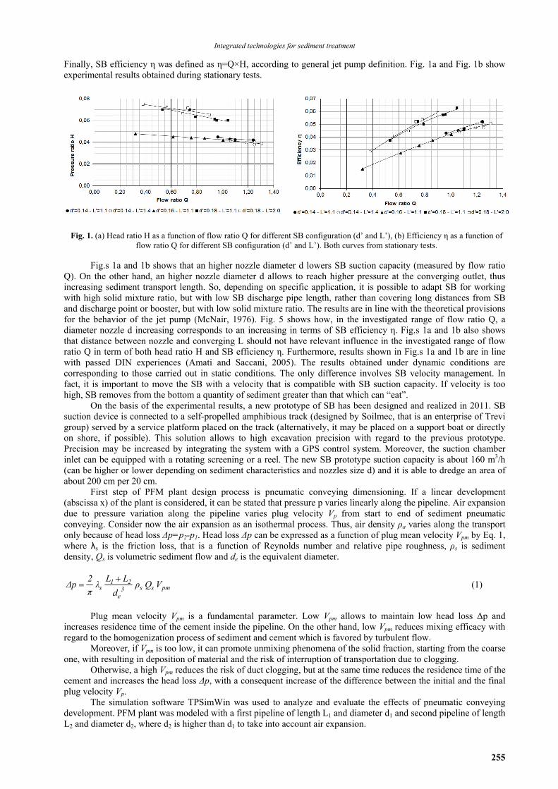
Finally, SB efficiency η was defined as η=Q×H, according to general jet pump definition. Fig. 1a and Fig. 1b show experimental results obtained during stationary tests.
Fig. 1. (a) Head ratio H as a function of flow ratio Q for different SB configuration (d’ and L’), (b) Efficiency η as a function of flow ratio Q for different SB configuration (d’ and L’). Both curves from stationary tests.
Fig.s 1a and 1b shows that an higher nozzle diameter d lowers SB suction capacity (measured by flow ratio
Q). On the other hand, an higher nozzle diameter d allows to reach higher pressure at the converging outlet, thus increasing sediment transport length. So, depending on specific application, it is possible to adapt SB for working with high solid mixture ratio, but with low SB discharge pipe length, rather than covering long distances from SB and discharge point or booster, but with low solid mixture ratio. The results are in line with the theoretical provisions for the behavior of the jet pump (McNair, 1976). Fig. 5 shows how, in the investigated range of flow ratio Q, a diameter nozzle d increasing corresponds to an increasing in terms of SB efficiency η. Fig.s 1a and 1b also shows that distance between nozzle and converging L should not have relevant influence in the investigated range of flow ratio Q in term of both head ratio H and SB efficiency η. Furthermore, results shown in Fig.s 1a and 1b are in line with passed DIN experiences (Amati and Saccani, 2005). The results obtained under dynamic conditions are corresponding to those carried out in static conditions. The only difference involves SB velocity management. In fact, it is important to move the SB with a velocity that is compatible with SB suction capacity. If velocity is too high, SB removes from the bottom a quantity of sediment greater than that which can “eat”.
On the basis of the experimental results, a new prototype of SB has been designed and realized in 2011. SB suction device is connected to a self-propelled amphibious track (designed by Soilmec, that is an enterprise of Trevi group) served by a service platform placed on the track (alternatively, it may be placed on a support boat or directly on shore, if possible). This solution allows to high excavation precision with regard to the previous prototype. Precision may be increased by integrating the system with a GPS control system. Moreover, the suction chamber inlet can be equipped with a rotating screening or a reel. The new SB prototype suction capacity is about 160 m3/h (can be higher or lower depending on sediment characteristics and nozzles size d) and it is able to dredge an area of about 200 cm per 20 cm.
First step of PFM plant design process is pneumatic conveying dimensioning. If a linear development (abscissa x) of the plant is considered, it can be stated that pressure p varies linearly along the pipeline. Air expansion due to pressure variation along the pipeline varies plug velocity Vp from start to end of sediment pneumatic conveying. Consider now the air expansion as an isothermal process. Thus, air density ρa varies along the transport only because of head loss Δp=p2-p1. Head loss Δp can be expressed as a function of plug mean velocity Vpm by Eq. 1, where λs is the friction loss, that is a function of Reynolds number and relative pipe roughness, ρs is sediment density, Qs is volumetric sediment flow and de is the equivalent diameter.
pmss3e
21s V Q ρ
d
LLλ
π
2Δp
(1)
Plug mean velocity Vpm is a fundamental parameter. Low Vpm allows to maintain low head loss Δp and
increases residence time of the cement inside the pipeline. On the other hand, low Vpm reduces mixing efficacy with regard to the homogenization process of sediment and cement which is favored by turbulent flow.
Moreover, if Vpm is too low, it can promote unmixing phenomena of the solid fraction, starting from the coarse one, with resulting in deposition of material and the risk of interruption of transportation due to clogging.
Otherwise, a high Vpm reduces the risk of duct clogging, but at the same time reduces the residence time of the cement and increases the head loss Δp, with a consequent increase of the difference between the initial and the final plug velocity Vp.
The simulation software TPSimWin was used to analyze and evaluate the effects of pneumatic conveying development. PFM plant was modeled with a first pipeline of length L1 and diameter d1 and second pipeline of length L2 and diameter d2, where d2 is higher than d1 to take into account air expansion.
Bianchini et al./Environmental Engineering and Management Journal 12 (2013), S11, Supplement, 253-256
256
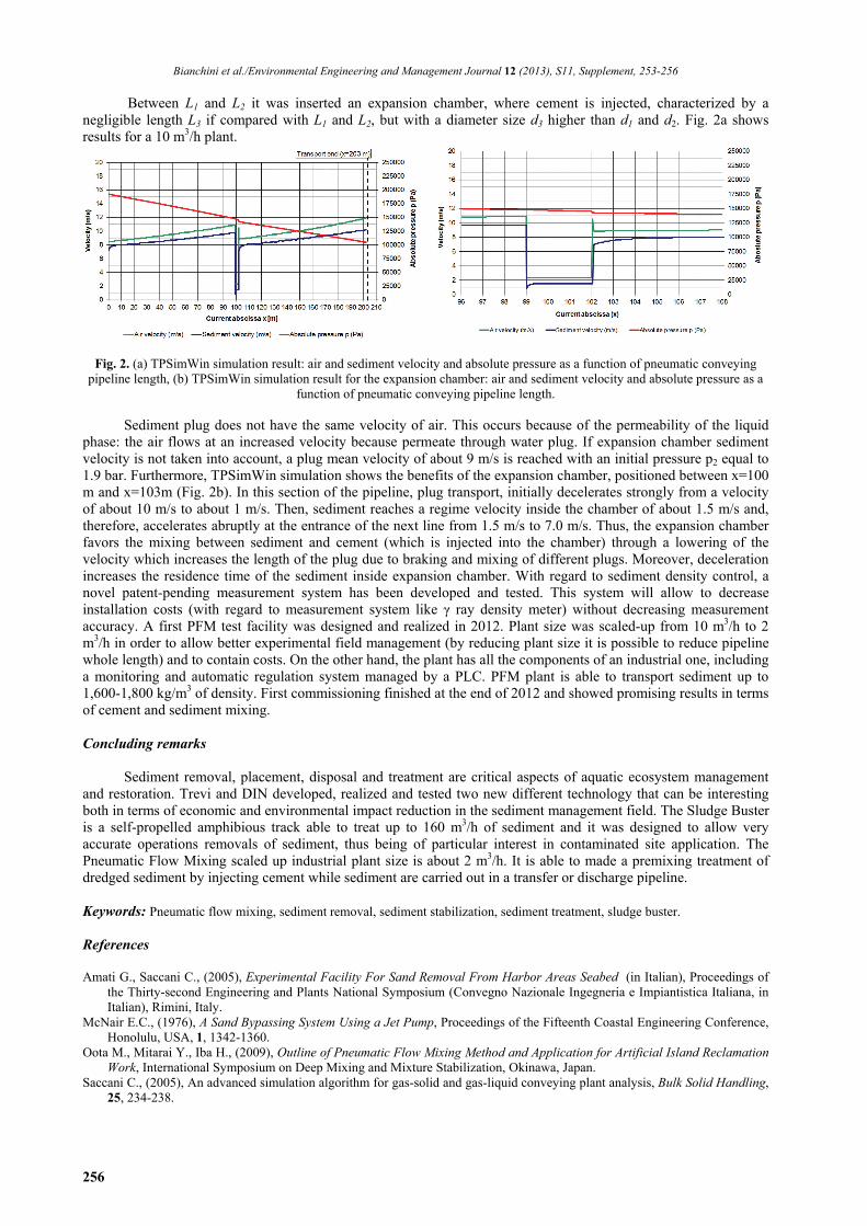
Between L1 and L2 it was inserted an expansion chamber, where cement is injected, characterized by a negligible length L3 if compared with L1 and L2, but with a diameter size d3 higher than d1 and d2. Fig. 2a shows results for a 10 m3/h plant.
Fig. 2. (a) TPSimWin simulation result: air and sediment velocity and absolute pressure as a function of pneumatic conveying pipeline length, (b) TPSimWin simulation result for the expansion chamber: air and sediment velocity and absolute pressure as a
function of pneumatic conveying pipeline length.
Sediment plug does not have the same velocity of air. This occurs because of the permeability of the liquid phase: the air flows at an increased velocity because permeate through water plug. If expansion chamber sediment velocity is not taken into account, a plug mean velocity of about 9 m/s is reached with an initial pressure p2 equal to 1.9 bar. Furthermore, TPSimWin simulation shows the benefits of the expansion chamber, positioned between x=100 m and x=103m (Fig. 2b). In this section of the pipeline, plug transport, initially decelerates strongly from a velocity of about 10 m/s to about 1 m/s. Then, sediment reaches a regime velocity inside the chamber of about 1.5 m/s and, therefore, accelerates abruptly at the entrance of the next line from 1.5 m/s to 7.0 m/s. Thus, the expansion chamber favors the mixing between sediment and cement (which is injected into the chamber) through a lowering of the velocity which increases the length of the plug due to braking and mixing of different plugs. Moreover, deceleration increases the residence time of the sediment inside expansion chamber. With regard to sediment density control, a novel patent-pending measurement system has been developed and tested. This system will allow to decrease installation costs (with regard to measurement system like γ ray density meter) without decreasing measurement accuracy. A first PFM test facility was designed and realized in 2012. Plant size was scaled-up from 10 m3/h to 2 m3/h in order to allow better experimental field management (by reducing plant size it is possible to reduce pipeline whole length) and to contain costs. On the other hand, the plant has all the components of an industrial one, including a monitoring and automatic regulation system managed by a PLC. PFM plant is able to transport sediment up to 1,600-1,800 kg/m3 of density. First commissioning finished at the end of 2012 and showed promising results in terms of cement and sediment mixing. Concluding remarks
Sediment removal, placement, disposal and treatment are critical aspects of aquatic ecosystem management and restoration. Trevi and DIN developed, realized and tested two new different technology that can be interesting both in terms of economic and environmental impact reduction in the sediment management field. The Sludge Buster is a self-propelled amphibious track able to treat up to 160 m3/h of sediment and it was designed to allow very accurate operations removals of sediment, thus being of particular interest in contaminated site application. The Pneumatic Flow Mixing scaled up industrial plant size is about 2 m3/h. It is able to made a premixing treatment of dredged sediment by injecting cement while sediment are carried out in a transfer or discharge pipeline. Keywords: Pneumatic flow mixing, sediment removal, sediment stabilization, sediment treatment, sludge buster. References Amati G., Saccani C., (2005), Experimental Facility For Sand Removal From Harbor Areas Seabed (in Italian), Proceedings of
the Thirty-second Engineering and Plants National Symposium (Convegno Nazionale Ingegneria e Impiantistica Italiana, in Italian), Rimini, Italy.
McNair E.C., (1976), A Sand Bypassing System Using a Jet Pump, Proceedings of the Fifteenth Coastal Engineering Conference, Honolulu, USA, 1, 1342-1360.
Oota M., Mitarai Y., Iba H., (2009), Outline of Pneumatic Flow Mixing Method and Application for Artificial Island Reclamation Work, International Symposium on Deep Mixing and Mixture Stabilization, Okinawa, Japan.
Saccani C., (2005), An advanced simulation algorithm for gas-solid and gas-liquid conveying plant analysis, Bulk Solid Handling, 25, 234-238.


![Figures - United States Environmental Protection … _studies2004...slurry simulation (M1S2) with sediment sample S2 and water sample [2a] Prepare dredged material slurry simulation](https://img.pdfslide.us/doc/110x75/5e785d6ef6ed39728b16dbf0/figures-united-states-environmental-protection-studies2004-slurry-simulation.jpg)