Embed Size (px)
Citation preview
© 2014 Cisco and/or its affiliates. All rights reserved. Page 1 of 20
White Paper
Integrated Enterprise SCADA System Architectures for Safe and Efficient Pipeline Operations
Brian Malkinson, Global Solution Architect, Pipeline Management Systems, Schneider Electric Rik Irons-Mclean, Lead Architect Oil and Gas, IoE Vertical Solutions Group, Cisco Systems
Contents
Introduction ................................................................................................................................................................ 2 Pipeline Management Systems ................................................................................................................................ 4 SCADA System Design Principles ........................................................................................................................... 5 Common Virtualized Platform Architecture ............................................................................................................ 8 Distributed Architecture ......................................................................................................................................... 14 Decision Support ..................................................................................................................................................... 15 Disaster-Recovery Architecture ............................................................................................................................. 16 Conclusion ............................................................................................................................................................... 18 Additional Resources .............................................................................................................................................. 20
© 2014 Cisco and/or its affiliates. All rights reserved. Page 2 of 20
Introduction Oil and gas pipeline management is challenging, with pipelines often running over large geographical distances, through harsh environments, and with limited communications and power infrastructure available. In addition, pipelines must comply with stringent environmental regulations and operate as safely as possible, as well as addressing growing cyber and physical security threats.
Critical pipeline requirements, however, have not changed. Pipeline integrity, safety, security, and reliability are essential elements that help operators meet demanding delivery schedules and optimize operational costs.
Validated designs make deploying host pipeline management system environments easier. Validated designs describe solutions using blade and rack servers that are designed, tested, and documented, much like a deployment recipe, to facilitate, simplify, and improve customer deployments. These designs incorporate a wide range of technologies and products into solutions that have been developed to address customers’ business needs.
An integrated design delivers on the promise of maximum reliability with a single cohesive system that integrates Supervisory Control and Data Acquisition (SCADA) services with network and data traffic, embedded management, and powerful servers with high-speed hard disks and memory. Integrated design provides performance through a better architecture and better balance of resources that:
● Simplifies physical and virtual networks, reducing cost while increasing manageability
● Scales better and more rapidly and with lower infrastructure cost per server
● Delivers greater flexibility with virtualized environments for development and testing
● Increases an organization’s responsiveness to changing workloads and business conditions through increased flexibility
This document describes integrated design, looking at how its three main components—SCADA principles, converged networking, and powerful servers—solve the requirements of high-availability SCADA systems.
With a jointly architected and validated approach to pipeline management, networking, and computing (Figure 1), realizable benefits can be significant. Solution integration quality and interoperability are maximized, while design and testing time are minimized. End users have a single point of reference accountable for integration and operational success from hardware, software, security, and management perspectives throughout the lifecycle of a project. The jointly architected design will provide maximum benefit for current operations and be a platform for future application enablement and integration.
© 2014 Cisco and/or its affiliates. All rights reserved. Page 3 of 20
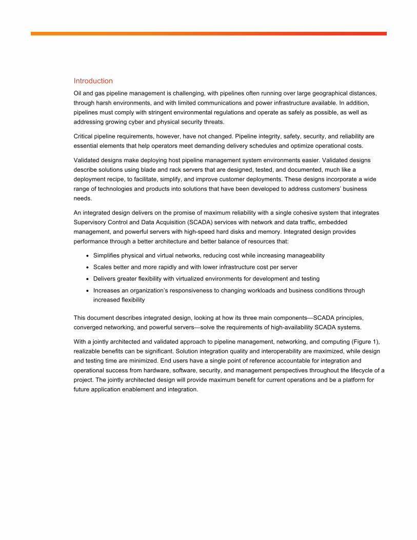
Figure 1. SCADA System Architecture
Transmission pipelines are the key transport mechanism of the oil and gas industry, operating continuously 24 hours a day, 365 days a year. Pipelines provide an efficient, safe, and cost-effective way to transport processed or unprocessed oil, gas, and raw materials and products both on- and offshore. It is essential that they operate as safely and efficiently as possible, and where problems occur be able to rapidly restore normal operation to meet environmental, safety, and quality requirements. To do so requires a unified solution including integrated monitoring, management, safety, and information systems for pipeline operation, as well as computing and network equipment.
A well-designed pipeline management system uses a hardware and software architecture that allows functions to be mobile, scalable, flexible, and robust. It also permits distribution of processing among different SCADA system components to optimize overall performance of the pipeline management system. The architecture of the pipeline management system uses non-proprietary industry standards such as TCP/IP, ANSI Structured Query Language (SQL), Open Database Connectivity (ODBC) and Component Object Model (COM) interfaces, and XML encoding. Pipeline management system design principles include security, innovation, standardization, reliability, longevity, and regulatory readiness.
© 2014 Cisco and/or its affiliates. All rights reserved. Page 4 of 20
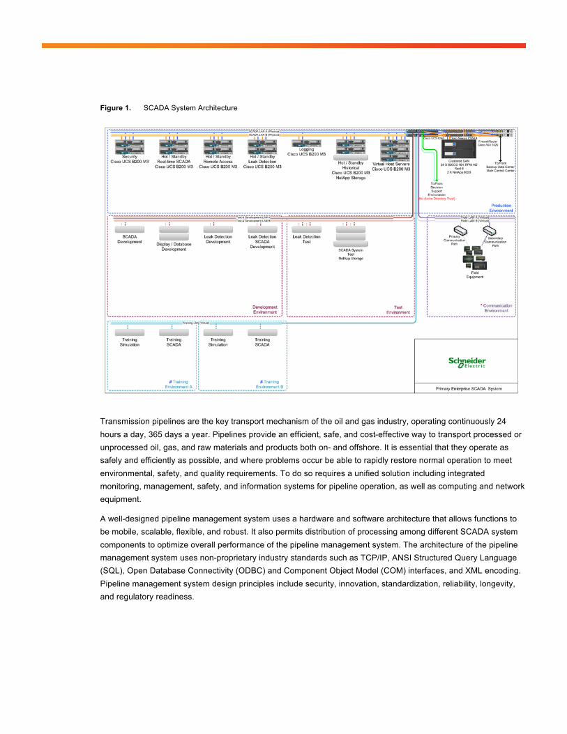
Pipeline Management Systems Pipeline control systems consist of multiple services and systems applications to facilitate safe and efficient operations (Figure 2):
A pipeline management system combines operational SCADA with real-time applications specific to the oil and gas industry, host-based leak detection, and historical flow measurement. These integrated applications provide pipeline operators:
● Real-time control and supervision of pipeline operations using a symmetric designed SCADA system
● Accurate measurement of flow, volume, and levels to ensure correct product accounting
● Detecting and locating pipeline leakage including time, volumes, and location distances
● Integrated security systems for personnel, the environment, and infrastructure using video surveillance, access control, and intrusion-detection systems
● Safe operations through instrumentation and safety systems
● Energy management system to visualize, manage, and optimize energy consumption
Figure 2. Pipeline Management System Modules
● RealTime SCADA: Schneider Electric’s OASyS DNA transcends the traditional SCADA environment to incorporate the workflow needs of customers in real time. OASyS DNA is an infrastructure product that adapts to the diverse and changing needs of your enterprise. From the field to the enterprise, OASyS DNA allows you to access operational and historical data securely at anytime from anywhere.
● Oil and Gas Application Suite: Schneider Electric’s RealTime Oil and Gas Suite works with the proven Schneider Electric OASyS DNA SCADA system to centralize delivery of key oil and gas pipeline information, enhancing your company’s operational environment. You receive the critical data you need to improve pipeline operations and meet your business goals. Schneider Electric offers up-to-the-minute

© 2014 Cisco and/or its affiliates. All rights reserved. Page 5 of 20
metering and flow totalling; and calculates and monitors line pack, tank storage, hydraulic profiles, and compressor and pump performance in real time.
● Leak detection: The main strength of Schneider Electric’s SimSuite Pipeline lies in its ability to accurately model the pipeline more completely than other available solutions. The leak-detection application uses a combination of methods to detect and locate leaks. Leaks can occur anywhere on the pipeline; they can vary in size; and they can be caused by fatigue, corrosion, equipment failure, and theft. Large and small leaks can be detected using multiple mass-balance calculations. Pressure-drop calculations can be used to locate the leak.
● Measurement data: The Schneider Electric Measurement Advisor, empowered with Schneider Electric’s advanced measurement user interface, provides the efficient and accurate means to configure devices and collect, validate, modify, and reconcile your oil and gas measurement data. Part of the Schneider Electric suite of oil and gas solutions, Schneider Electric Measurement Advisor is the high-mileage solution that gathers measurements for multiple pipelines that interface with various Ethernet in the First Mile (EFM) polling engines, SCADA systems, chart integrators, third-parties, and manual input. Schneider Electric Measurement Advisor allows the precision required at every step to achieve process-wide accuracy.
SCADA System Design Principles
Security Few industries require security more than those concerned with the protection of natural resources and the management of energy. Although the use of remote monitoring and control in critical processes continues to evolve, so does the need for enhanced security. Whether it is a measured value at a field instrument or the data path to the host, informational integrity can be realized only through focus on end-to-end data security:
● Alignment with government and industry
◦ Proactive participation with industry and customer groups
● Partnerships with experts in security
● Commitment to product security
● Out-of-the-box” adaptable, secure systems
◦ No back doors for any reason
◦ Policy-Based Encryption
● Security Lifecycle management
Innovation Taking advantage of the latest in proven technologies in product development includes forming partnerships with industry leaders:
● Global Information Systems (GIS)
● Extended historians
● Financial systems
● Measurement systems
● Security agencies
● Video surveillance
© 2014 Cisco and/or its affiliates. All rights reserved. Page 6 of 20
● Alarm management
● Standardization: This should incorporate middleware and integration tools: Integrate presentation, logic, and data
● Publish and subscribe, including real-time performance and integrity
● Integrate business intelligence objects
◦ Application programming interfaces (APIs) and “connectors” to other enterprise middleware products
◦ WCF - .NET Framework 3.0 and Remote Desktop Protocol (RDP)
◦ Business Logic Tiers (BLTs)
● SQL engine: Standard SQL
● Directory services:
◦ Active Directory (AD)
◦ AD Lightweight Directory Services (AD LDS)
Reliability Pipeline operations applications and services run in real or near real-time, 24 hours a day, and the network must be available to users on a continuous basis, with little or no downtime. Operational pipeline management systems offer efficiency and reliability when they are working properly, but to know whether or not they are, you need real-time access to network health information across the system. A well-designed pipeline management system provides direct access to network communication statistics from right-to-use (RTU) licenses, data radios, and field instruments as well as host indicators; CPU; memory; and network usage. Designs incorporate a field-proven redundancy model for:
● Systemwide health monitoring
● Multipath communication redundancy
● Field-proven real-time performance
● Multisystem models for disaster recovery and contingency centers
● Flexible control strategies
Longevity It is essential to protect customers’ investment in pipeline management system technology
● Use of extensible products when building
● Product migration planning and testing
● Short- and Long-term technology planning to help reduce costs and risks associated with changes in core technologies
© 2014 Cisco and/or its affiliates. All rights reserved. Page 7 of 20
Regulatory As industry leader committed to ensuring its products meet or exceed industry standards, increased attention to safety and compliance with emerging regulations are major design factors for telemetry and SCADA systems today. Governments on both federal and municipal levels continue to push for higher standards in water quality, affordable energy, and the well-managed distribution of both in a manner that sustains our natural environment. Regulatory bodies include: Pipeline and Hazardous Materials Safety Administration (PHMSA)
● API 1167 Alarm Management Workgroup, AGA Alarm Management Committee
● AGA, API, and ISA
● TCSP – SCADA Certification
● Pipes Act 2006
● API 1165 SCADA Display Recommended Best Practices
● Control Room Management: Alarm Management, API RP 1168
● Operator training that includes simulator or noncomputerized simulations
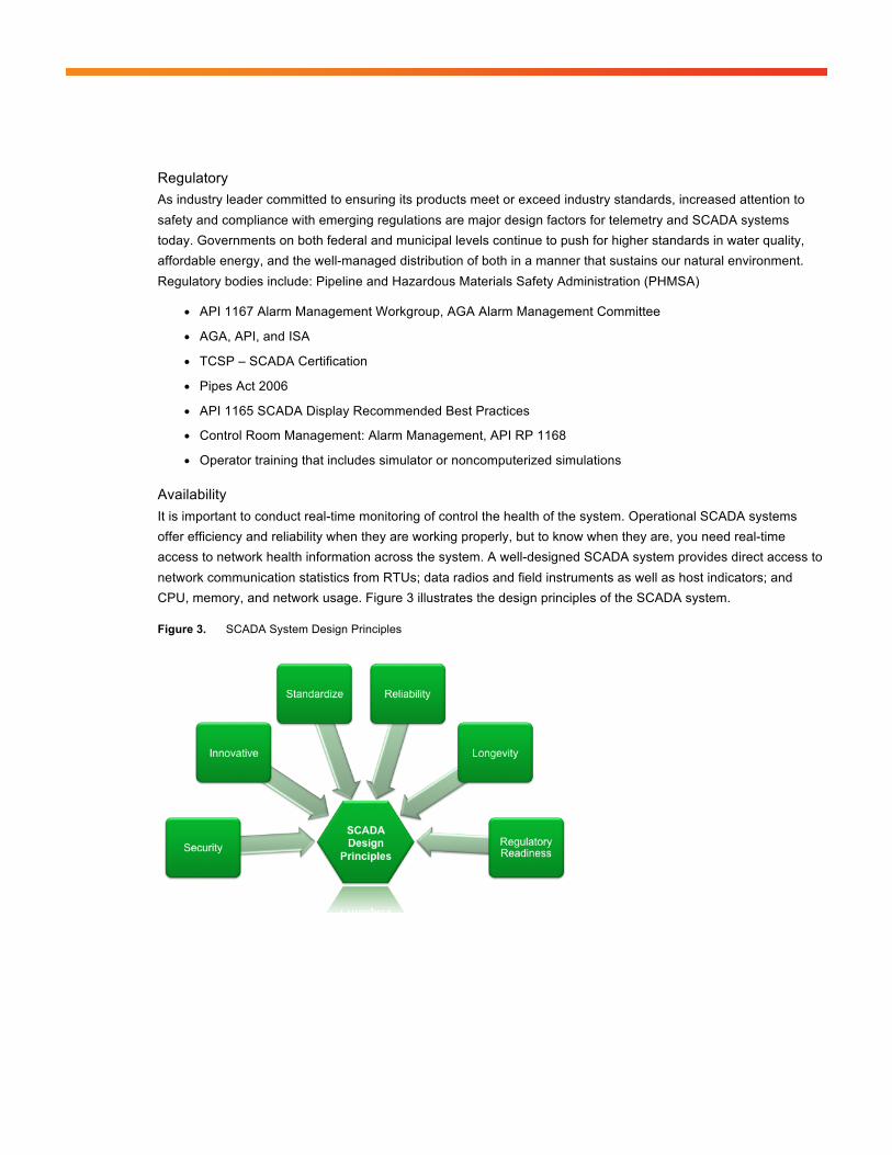
Availability It is important to conduct real-time monitoring of control the health of the system. Operational SCADA systems offer efficiency and reliability when they are working properly, but to know when they are, you need real-time access to network health information across the system. A well-designed SCADA system provides direct access to network communication statistics from RTUs; data radios and field instruments as well as host indicators; and CPU, memory, and network usage. Figure 3 illustrates the design principles of the SCADA system.
Figure 3. SCADA System Design Principles
© 2014 Cisco and/or its affiliates. All rights reserved. Page 8 of 20
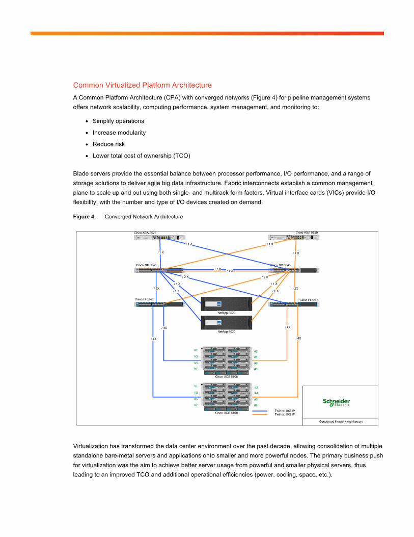
Common Virtualized Platform Architecture A Common Platform Architecture (CPA) with converged networks (Figure 4) for pipeline management systems offers network scalability, computing performance, system management, and monitoring to:
● Simplify operations
● Increase modularity
● Reduce risk
● Lower total cost of ownership (TCO)
Blade servers provide the essential balance between processor performance, I/O performance, and a range of storage solutions to deliver agile big data infrastructure. Fabric interconnects establish a common management plane to scale up and out using both single- and multirack form factors. Virtual interface cards (VICs) provide I/O flexibility, with the number and type of I/O devices created on demand.
Figure 4. Converged Network Architecture
Virtualization has transformed the data center environment over the past decade, allowing consolidation of multiple standalone bare-metal servers and applications onto smaller and more powerful nodes. The primary business push for virtualization was the aim to achieve better server usage from powerful and smaller physical servers, thus leading to an improved TCO and additional operational efficiencies (power, cooling, space, etc.).
© 2014 Cisco and/or its affiliates. All rights reserved. Page 9 of 20
As the server virtualization architecture was adopted, emerging applications took advantage of the “horizontal” scalability provided through multiple virtual machines, thus allowing deployment of these applications without purchasing additional server hardware.
Greater physical resource usage is achieved by balancing application workloads across a large pool of servers in real time, responding more quickly to changes in workload or server availability by moving virtual machines between physical servers.
However, virtualization can create many challenges that a joint Schneider and Cisco control-center solution must resolve to provide maximum benefit for pipeline operations:
● Added cost and complexity due to the sheer number of interfaces, cables, and upstream switch ports to support each server
● Management difficulties due to multiple layers of hardware and software switching
● Too many management points, making it difficult to manage quality of service (QoS) and maintain security
● Scalability challenges caused by the amount of time needed to configure servers and integrate them into the network infrastructure
● Overhead of virtualized environments and constraints on resources hampering performance
● Virtual machine and operating system sprawl, contributing to management challenges
To meet these challenges a Schneider pipeline management solution running on a Cisco Unified Computing System™ (Cisco UCS®) delivers abstracted hardware and server virtualization through a unified system fabric, integrated single management point, and powerful best-in-class servers. The Cisco UCS takes advantage of Cisco’s comprehensive expertise in delivering highly optimized architectures and dynamic balancing of resources to deliver world-record-setting virtualization performance that:
● Simplifies physical and virtual networks, reducing cost while increasing manageability
● Scales easily and rapidly, with lower infrastructure cost per server
● Delivers greater performance for virtualized environments through a better balance of resources
● Increases an organization’s responsiveness to changing workloads and business conditions through increased flexibility
A principal design element of Cisco UCS is to break away from old static IT data center models and deliver on a new IT model that pools server, storage, and networking resources into a flexible virtualized environment that can be provisioned (or re-provisioned) as workload and business demands require.
© 2014 Cisco and/or its affiliates. All rights reserved. Page 10 of 20
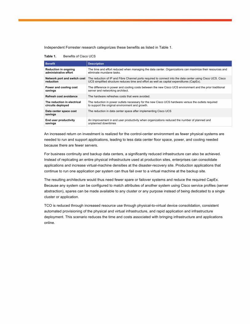
Independent Forrester research categorizes these benefits as listed in Table 1.
Table 1. Benefits of Cisco UCS
Benefit Description
Reduction in ongoing administrative effort
The time and effort reduced when managing the data center. Organizations can maximize their resources and eliminate mundane tasks.
Network port and switch cost reduction
The reduction of IP and Fibre Channel ports required to connect into the data center using Cisco UCS. Cisco UCS simplified structure reduces time and effort as well as capital expenditures (CapEx).
Power and cooling cost savings
The difference in power and cooling costs between the new Cisco UCS environment and the prior traditional server and networking architect.
Refresh cost avoidance The hardware refreshes costs that were avoided.
The reduction in electrical circuits deployed
The reduction in power outlets necessary for the new Cisco UCS hardware versus the outlets required to support the original environment and growth.
Data center space cost savings
The reduction in data center space after implementing Cisco UCS
End user productivity savings
An improvement in end user productivity when organizations reduced the number of planned and unplanned downtimes
An increased return on investment is realized for the control-center environment as fewer physical systems are needed to run and support applications, leading to less data center floor space, power, and cooling needed because there are fewer servers.
For business continuity and backup data centers, a significantly reduced infrastructure can also be achieved. Instead of replicating an entire physical infrastructure used at production sites, enterprises can consolidate applications and increase virtual-machine densities at the disaster-recovery site. Production applications that continue to run one application per system can thus fail over to a virtual machine at the backup site.
The resulting architecture would thus need fewer spare or failover systems and reduce the required CapEx. Because any system can be configured to match attributes of another system using Cisco service profiles (server abstraction), spares can be made available to any cluster or any purpose instead of being dedicated to a single cluster or application.
TCO is reduced through increased resource use through physical-to-virtual device consolidation, consistent automated provisioning of the physical and virtual infrastructure, and rapid application and infrastructure deployment. This scenario reduces the time and costs associated with bringing infrastructure and applications online.
© 2014 Cisco and/or its affiliates. All rights reserved. Page 11 of 20
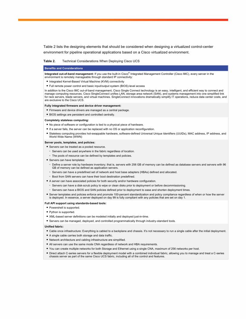
Table 2 lists the designing elements that should be considered when designing a virtualized control-center environment for pipeline operational applications based on a Cisco virtualized environment.
Table 2. Technical Considerations When Deploying Cisco UCS
Benefits and Considerations
Integrated out-of-band management: If you use the built-in Cisco® Integrated Management Controller (Cisco IMC), every server in the environment is remotely manageable through standard IP connectivity: ● Integrated Kernel-Based Virtual Machine (KVM) connectivity ● Full remote power control and basic input/output system (BIOS)-level access
In addition to the Cisco IMC out-of-band management, Cisco Single Connect technology is an easy, intelligent, and efficient way to connect and manage computing resources. Cisco SingleConnect unifies LAN, storage area network (SAN), and systems management into one simplified link for rack servers, blade servers, and virtual machines. SingleConnect innovations dramatically simplify IT operations, reduce data center costs, and are exclusive to the Cisco UCS.
Fully integrated firmware and device driver management: ● Firmware and device drivers are managed as a central package. ● BIOS settings are persistent and controlled centrally.
Completely stateless computing: ● No piece of software or configuration is tied to a physical piece of hardware. ● If a server fails, the server can be replaced with no OS or application reconfiguration. ● Stateless computing provides hot-swappable hardware, software-defined Universal Unique Identifiers (UUIDs), MAC address, IP address, and
World Wide Name (WWN)
Server pools, templates, and policies: ● Servers can be treated as a pooled resource. ◦ Servers can be used anywhere in the fabric regardless of location. ◦ The pools of resource can be defined by templates and policies.
● Servers can have templates: ◦ Define a server role by hardware inventory; that is, servers with 256 GB of memory can be defined as database servers and servers with 96
GB of memory can be defined as application servers. ◦ Servers can have a predefined set of network and host base adapters (HBAs) defined and allocated. ◦ Boot from SAN servers can have their boot destination predefined.
● A server can have associated policies for both security and/or hardware configuration. ◦ Servers can have a disk-scrub policy to wipe or clean disks prior to deployment or before decommissioning. ◦ Servers can have a BIOS and SAN policies defined prior to deployment to ease and shorten deployment times.
● Server templates and policies enforce and promote 100-percent standardization and policy compliance regardless of when or how the server is deployed. In essence, a server deployed on day 99 is fully compliant with any policies that are set on day 1.
Full API support using standards-based tools: ● Powershell is supported. ● Python is supported. ● XML-based server definitions can be modeled initially and deployed just-in-time. ● Servers can be managed, deployed, and controlled programmatically through industry-standard tools.
Unified fabric: ● Cable once infrastructure: Everything is cabled to a backplane and chassis. It’s not necessary to run a single cable after the initial deployment. ● A single cable carries both storage and data traffic. ● Network architecture and cabling infrastructure are simplified. ● All servers can use the same mode CNA regardless of network and HBA requirements. ● You can create multiple networks for both Storage and Ethernet using a single CNA, maximum of 256 networks per host. ● Direct attach C-series servers for a flexible deployment model with a combined individual fabric, allowing you to manage and treat a C-series
chassis server as part of the same Cisco UCS fabric, including all of the control and features.
© 2014 Cisco and/or its affiliates. All rights reserved. Page 12 of 20
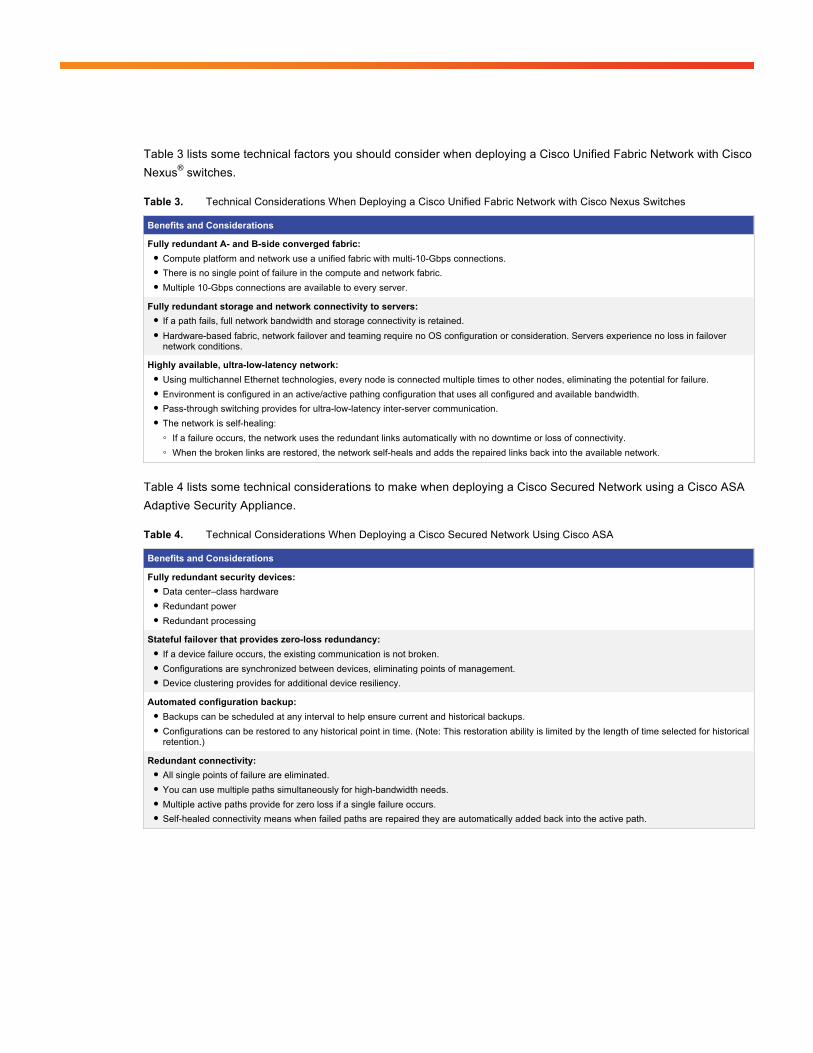
Table 3 lists some technical factors you should consider when deploying a Cisco Unified Fabric Network with Cisco Nexus® switches.
Table 3. Technical Considerations When Deploying a Cisco Unified Fabric Network with Cisco Nexus Switches
Benefits and Considerations
Fully redundant A- and B-side converged fabric: ● Compute platform and network use a unified fabric with multi-10-Gbps connections. ● There is no single point of failure in the compute and network fabric. ● Multiple 10-Gbps connections are available to every server.
Fully redundant storage and network connectivity to servers: ● If a path fails, full network bandwidth and storage connectivity is retained. ● Hardware-based fabric, network failover and teaming require no OS configuration or consideration. Servers experience no loss in failover
network conditions.
Highly available, ultra-low-latency network: ● Using multichannel Ethernet technologies, every node is connected multiple times to other nodes, eliminating the potential for failure. ● Environment is configured in an active/active pathing configuration that uses all configured and available bandwidth. ● Pass-through switching provides for ultra-low-latency inter-server communication. ● The network is self-healing: ◦ If a failure occurs, the network uses the redundant links automatically with no downtime or loss of connectivity. ◦ When the broken links are restored, the network self-heals and adds the repaired links back into the available network.
Table 4 lists some technical considerations to make when deploying a Cisco Secured Network using a Cisco ASA Adaptive Security Appliance.
Table 4. Technical Considerations When Deploying a Cisco Secured Network Using Cisco ASA
Benefits and Considerations
Fully redundant security devices: ● Data center–class hardware ● Redundant power ● Redundant processing
Stateful failover that provides zero-loss redundancy: ● If a device failure occurs, the existing communication is not broken. ● Configurations are synchronized between devices, eliminating points of management. ● Device clustering provides for additional device resiliency.
Automated configuration backup: ● Backups can be scheduled at any interval to help ensure current and historical backups. ● Configurations can be restored to any historical point in time. (Note: This restoration ability is limited by the length of time selected for historical
retention.)
Redundant connectivity: ● All single points of failure are eliminated. ● You can use multiple paths simultaneously for high-bandwidth needs. ● Multiple active paths provide for zero loss if a single failure occurs. ● Self-healed connectivity means when failed paths are repaired they are automatically added back into the active path.
© 2014 Cisco and/or its affiliates. All rights reserved. Page 13 of 20
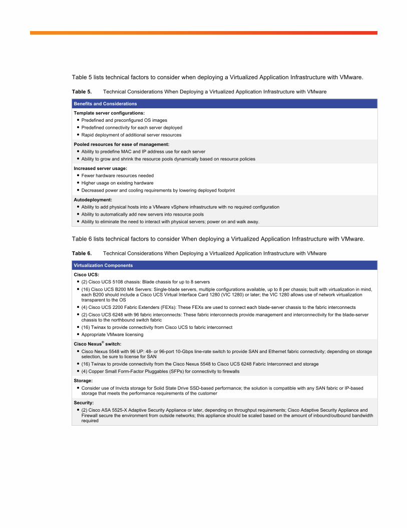
Table 5 lists technical factors to consider when deploying a Virtualized Application Infrastructure with VMware.
Table 5. Technical Considerations When Deploying a Virtualized Application Infrastructure with VMware
Benefits and Considerations
Template server configurations: ● Predefined and preconfigured OS images ● Predefined connectivity for each server deployed ● Rapid deployment of additional server resources
Pooled resources for ease of management: ● Ability to predefine MAC and IP address use for each server ● Ability to grow and shrink the resource pools dynamically based on resource policies
Increased server usage: ● Fewer hardware resources needed ● Higher usage on existing hardware ● Decreased power and cooling requirements by lowering deployed footprint
Autodeployment: ● Ability to add physical hosts into a VMware vSphere infrastructure with no required configuration ● Ability to automatically add new servers into resource pools ● Ability to eliminate the need to interact with physical servers; power on and walk away.
Table 6 lists technical factors to consider When deploying a Virtualized Application Infrastructure with VMware.
Table 6. Technical Considerations When Deploying a Virtualized Application Infrastructure with VMware
Virtualization Components
Cisco UCS: ● (2) Cisco UCS 5108 chassis: Blade chassis for up to 8 servers ● (16) Cisco UCS B200 M4 Servers: Single-blade servers, multiple configurations available, up to 8 per chassis; built with virtualization in mind,
each B200 should include a Cisco UCS Virtual Interface Card 1280 (VIC 1280) or later; the VIC 1280 allows use of network virtualization transparent to the OS
● (4) Cisco UCS 2200 Fabric Extenders (FEXs): These FEXs are used to connect each blade-server chassis to the fabric interconnects ● (2) Cisco UCS 6248 with 96 fabric interconnects: These fabric interconnects provide management and interconnectivity for the blade-server
chassis to the northbound switch fabric ● (16) Twinax to provide connectivity from Cisco UCS to fabric interconnect ● Appropriate VMware licensing
Cisco Nexus® switch: ● Cisco Nexus 5548 with 96 UP: 48- or 96-port 10-Gbps line-rate switch to provide SAN and Ethernet fabric connectivity; depending on storage
selection, be sure to license for SAN ● (16) Twinax to provide connectivity from the Cisco Nexus 5548 to Cisco UCS 6248 Fabric Interconnect and storage ● (4) Copper Small Form-Factor Pluggables (SFPs) for connectivity to firewalls
Storage: ● Consider use of Invicta storage for Solid State Drive SSD-based performance; the solution is compatible with any SAN fabric or IP-based
storage that meets the performance requirements of the customer
Security: ● (2) Cisco ASA 5525-X Adaptive Security Appliance or later, depending on throughput requirements; Cisco Adaptive Security Appliance and
Firewall secure the environment from outside networks; this appliance should be scaled based on the amount of inbound/outbound bandwidth required
© 2014 Cisco and/or its affiliates. All rights reserved. Page 14 of 20
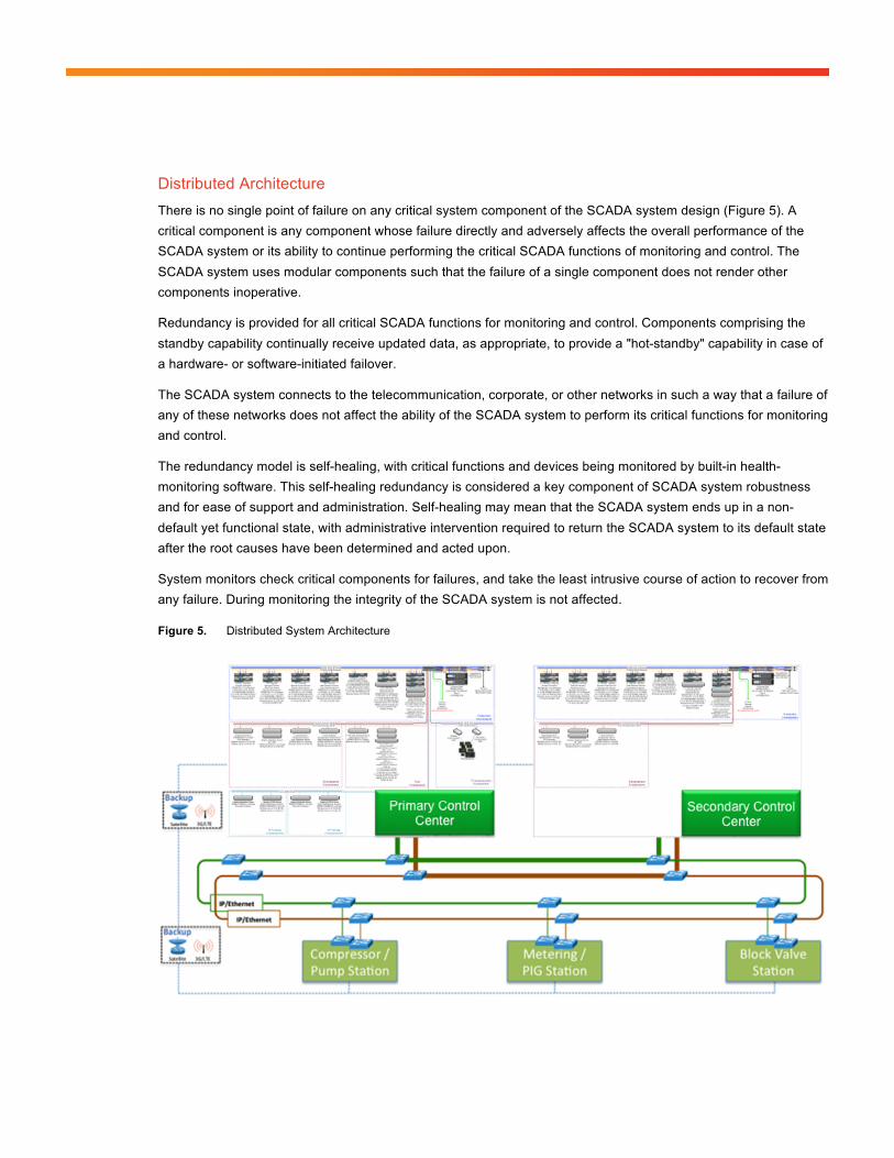
Distributed Architecture There is no single point of failure on any critical system component of the SCADA system design (Figure 5). A critical component is any component whose failure directly and adversely affects the overall performance of the SCADA system or its ability to continue performing the critical SCADA functions of monitoring and control. The SCADA system uses modular components such that the failure of a single component does not render other components inoperative.
Redundancy is provided for all critical SCADA functions for monitoring and control. Components comprising the standby capability continually receive updated data, as appropriate, to provide a "hot-standby" capability in case of a hardware- or software-initiated failover.
The SCADA system connects to the telecommunication, corporate, or other networks in such a way that a failure of any of these networks does not affect the ability of the SCADA system to perform its critical functions for monitoring and control.
The redundancy model is self-healing, with critical functions and devices being monitored by built-in health-monitoring software. This self-healing redundancy is considered a key component of SCADA system robustness and for ease of support and administration. Self-healing may mean that the SCADA system ends up in a non-default yet functional state, with administrative intervention required to return the SCADA system to its default state after the root causes have been determined and acted upon.
System monitors check critical components for failures, and take the least intrusive course of action to recover from any failure. During monitoring the integrity of the SCADA system is not affected.
Figure 5. Distributed System Architecture
© 2014 Cisco and/or its affiliates. All rights reserved. Page 15 of 20
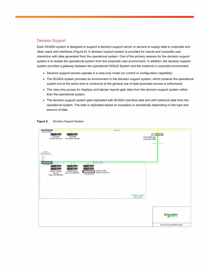
Decision Support Each SCADA system is designed to support a decision support server or servers to supply data to corporate and other users and interfaces (Figure 6). A decision support system is provided for casual and corporate user interaction with data generated from the operational system. One of the primary reasons for the decision support system is to isolate the operational system from the corporate user environment. In addition, the decision support system provides a gateway between the operational OASyS System and the customer’s corporate environment.
● Decision support servers operate in a view-only mode (no control or configuration capability).
● The SCADA system provides an environment in the decision support system, which protects the operational system but at the same time is conducive to the general use of data (provided access is authorized).
● The view-only access for displays and tabular reports gets data from the decision support system rather than the operational system.
● The decision support system gets replicated with SCADA real-time data and with historical data from the operational system. The data is replicated based on exception or periodically depending on the type and amount of data.
Figure 6. Decision Support System
© 2014 Cisco and/or its affiliates. All rights reserved. Page 16 of 20
Disaster-Recovery Architecture The SCADA system provides for one or more backup facilities. The backup system operates as a hot backup to the primary OASyS System at the primary control center.
● The real-time and historical data stored on the components located at the backup system are kept synchronized at all times with the primary system located in the primary control center.
● If the backup system is shut down or communications to the backup system fails, the backup system synchronizes both the real-time and the historical data with the primary system as soon as connectivity is restored.
● The backup system can run the entire operations if the system becomes unusable or unavailable. As a result the following must be considered:
◦ The backup system handles the full SCADA system load without affecting the performance of the SCADA system.
◦ There are enough operator stations at the backup facility for all of the regular operators of the SCADA system.
◦ The backup system can provide data to corporate and other users and interfaces.
◦ The backup system can communicate with the field devices.
● The backup system can take control of the entire SCADA system at any time.
● It is possible to test the backup system by running control from it periodically for days at a time or on a continual basis.
Applications Applications can be categorized as operational (those directly involved with supporting pipeline operations such as the SCADA or leak detection systems), and multiservice applications (those that either support pipeline operations such as video surveillance or are more concerned with business applications such as voice and corporate data). Applications include:
● Pipeline monitoring including host-based leak detection
● Fluid management services including batch tracking and metering
● Energy and power management
● Security systems
● Electronic operator logs
● Alarm processing and management
© 2014 Cisco and/or its affiliates. All rights reserved. Page 17 of 20
LAN Network Model A high-speed redundant LAN interconnects the computers of the SCADA systems, local real-time human machine interfaces (HMIs), and support equipment. The LAN consists of high-speed redundant interconnected switches. Support equipment incapable of direct connection to the LAN connects through terminal servers, routers, or workstations, as appropriate. Where appropriate, duplicate support equipment can be provided for each portion of the redundant LAN in such a fashion as to provide redundant functions through each of the LANs. The servers and controller workstations independently connect to each portion of the redundant LAN and have access to all support equipment on that LAN. The LAN configuration offers near-invisible dual LAN redundancy by using a single “virtual” LAN configuration concept. This model offers the high reliability of a dual LAN, while presenting the simplicity of a single LAN to the end user.
The network configuration provides a streamlined network model that allows dual redundancy, yet it looks like a single VLAN. The redundancy model is both robust and self-healing. When a single component fails, the partner of that component or redundant component takes over without affecting the rest of SCADA system. Single VLAN robustness is achieved through the provision of the following:
● Dual intelligent redundant switches: Each switch is interconnected, providing the advantage of network communication between switches and redundancy if one switch fails.
● Dual intelligent redundant network interface cards (NICs): Intelligent NICs and drivers allow the cards to sense when a network or the other card fails, resulting in the healthy card’s taking over.
● Floating IP addresses: For a pair of redundant servers, a single address is assigned to the active server, allowing connectivity to active servers without having to know what physical machine is currently active.
WAN Telecom Infrastructure WANs are logical extensions of LANs. Any interfaces between LANs and WANs are through approved and supplied boundary devices such as routers, bridges, and/or concentrators and data control units.
All LAN and WAN communication equipment supports the following common features, as applicable to the type of equipment used and desired functions:
● Network management: Simple Network Management Protocol (SNMP), Common Management Information Protocol (CMIP), or both
◦ Multiple network layer protocols: TCP/IP, X.25, etc.
◦ IP routing
◦ Destination address filtering
◦ Protocol filtering
◦ Source address filtering
◦ Spanning-tree algorithm
● Multilevel security to protect against cyber-attacks and non-intentional security threats, and centralized configurable policy-based services
● Capability to integrate optional services to support pipeline operations such as voice over IP (VoIP), local Wi-Fi access, mobility, collaboration tools, and Internet access
● Backup WAN services to help ensure operational continuity between geographic locations
© 2014 Cisco and/or its affiliates. All rights reserved. Page 18 of 20
● End-to-end communications network management, security management, and administration management—from the control room SCADA system to the field device
Networking Security Technology can provide not only excellent performance for oil and gas applications, but also a wide range of network security measures to maintain availability, integrity, and confidentiality of the automation and control systems. Availability is most often cited as the critical security requirement, keeping the automation and control systems operational. Integrity protects data and systems from intentional or accidental alteration. Confidentiality helps ensure that unauthorized users cannot access data. These network security advantages protect operational and multiservice assets. Security is maintained through a lifecycle of design, implementation, maintenance, and improvement. Security and administration policies are a key foundation for developing robust network security.
Vendors and customers must ensure that a proper firewall infrastructure is in place to ensure the components of the SCADA system network remain secure using routers with managed access control lists (ACLs) and routing tables using standard routing protocols. An enterprise access zone or demilitarized zone (DMZ) for the decision support system is a required component of this firewall infrastructure.
Conclusion Using a single unified system that combines computing, networking, and virtualization overcomes the limitations of traditional environments. These systems scale better and more rapidly and with lower infrastructure cost. They deliver greater performance through a better balance of resources. They simplify management for rapid deployment of physical and virtual machines, and for the first time equate physical and virtual networking to provide increased visibility and control. Single unified systems increase flexibility, letting you move workloads between servers without worrying about changes in network latency, and they allow resources to be shared so that the environment can expand and evolve without the constraints of physical partitioning between networks. These newly developed unified systems meet the demands of virtualized environments, and support multiple generations of server, network, and virtual interface technologies. For a virtualized environment that needs to excel both today and into the future, a single unified system is the choice that delivers on the promise of maximum reliability.
● CapEx savings: Innovative integrated enterprise pipeline management with pipeline operations applications, controllers and RTUs, and telecoms infrastructure, resulting in engineering cost savings through enhanced integration, and lower total installation costs through centralized project management
● Operating expenses (OpEx) savings: Through energy management and efficiency, maintenance optimization through remote monitoring, and reduced communications network complexity to manage
● Enhanced pipeline safety and reliability: Immediate response to leaks without false alarms, integrated security, secure power and reliable electrical distribution, and redundancy at all levels (control centers, SCADA servers, controllers, and telecoms for operational field and pipeline stations)
● Regulatory compliance with enhanced productivity: Embedded safety features to help ensure regulatory compliance and operations efficiency
● Address both physical and cyber security challenges: A converged network providing cyber security detection and mitigation, video surveillance, and access control, improving security and risk management through end-to-end application visibility and control
● Reduced power consumption: Power optimization technology to reduce costs and energy consumption when running a pipeline with the benefit of reduction in carbon emissions
© 2014 Cisco and/or its affiliates. All rights reserved. Page 19 of 20
● Efficient real-time pipeline operations: Complete and integrated suite of advanced gas and liquids applications to improve operational control, monitoring, and planning; and information management and business reporting for critical and comprehensive information with a minimum of effort
● Better infrastructure manageability and visibility: Helping ensure continued pipeline operations by identifying and resolving communications challenges before they happen, or rapidly fixing if they occur
● More efficient business processes for better financial and commercial governance: Accurate liquids and gas-flow-measurement data that supports accurate customer billing through coupling commercial transaction technology, automated critical accounting, and reporting tasks
● Training platform: Operational applications that continue to develop in the oil and gas industry, taking advantage of virtualization and available computing power online and offline; operator trainers can be built and deployed as part of day-to-day operations
Contributors Serhii Konovalov: Oil and Gas Vertical Lead, IoE Vertical Solutions Group, Cisco Systems Rodrigo Kaschny: Oil and Gas StruxureLabs Director, Smart Infrastructure, Schneider Electric Zach Webb: Customer Solutions Architect, IoT Sales, Cisco Systems Fazil Osman: Customer Solutions Architect, Global Enterprise Theatre, Cisco Systems Alan Acquatella: Director OilandGas Solutions Midstream, Schneider Electric Jean Noel Enckle: Partner Alliance Manager, ISGE, Cisco Systems
© 2014 Cisco and/or its affiliates. All rights reserved. Page 20 of 20
Additional Resources ● Schneider Pipeline Management Solution: http://www.schneider-electric.com.co/documents/local/xperience-
efficiency/Pipeline_Management_Solution.pdf
● Schneider—Best Practices in Leak Detection: http://www.slideshare.net/SchneiderElectric/multi-tiered-leak-detectiona42013-25743519
● Cisco Validated Designs: http://www.cisco.com/en/US/netsol/ns743/networking_solutions_program_home.html.
● A Platform Built for Server Virtualization: Cisco Unified Computing System http://www.cisco.com/c/en/us/products/collateral/servers-unified-computing/ucs-6100-series-fabric-interconnects/white_paper_c11-555663.pdf
● Cisco and VMware Joint Solution Brings Unprecedented Innovation to Create Flexible Virtual Environments: http://www.cisco.com/c/dam/en/us/solutions/collateral/data-center-virtualization/dc-partner-vmware/c22-599617-01_vSphere_sOview.pdf
● Delivering on the Promise of Virtualization: Cisco Unified Computing System: http://www.cisco.com/c/dam/en/us/solutions/collateral/switches/catalyst-6500-series-switches/virtualization.pdf
● Forrester Report: The Total Economic Impact of the Cisco Unified Computing System: http://www.cisco.com/c/dam/en/us/solutions/collateral/borderless-networks/advanced-services/total_economic_impact_forrester_research.pdf
● Deliver Fabric-Based Infrastructure for Virtualization and Cloud Computing: http://www.cisco.com/c/dam/en/us/solutions/collateral/switches/catalyst-6500-series-switches/white_paper_c11-706418.pdf
Printed in USA C11-732757-00 10/14