Embed Size (px)
Citation preview

INSTALLATION GUIDE
NZ AU BI EU
INTEGRATED COOLDRAWERTM
MULTI-TEMPERATURE DRAWER
RB90S model


3
CONTENTS
Safety and warnings 4
Integrated cooldrawertm 5
Supplied parts 5
Drawer panels 6
Handle kit 6
Product dimensions 7
Stainless steel panel dimensions 8
Custom panel dimensions — Single panel 9
Custom panel dimensions — Dual panel 10
Cabinetry dimensions — Framed 11
Cabinetry dimensions — Frameless 12
Electrical connection 13
Cabinetry preparation 14
Panel preparation 15
Attach power cord & trim brackets 16
Position product into cabinetry 16
Attach drawer panel 17
Secure product to cabinetry 18
Attach side trims to cabinetry 18
Attach false panel 18
Final checklist 19

4
SAFETY AND WARNINGS
! WARNING!
Electric Shock Hazard Failure to follow this advice may result in electrical shock or death.• Read and follow the safety and warnings outlined
in this installation guide before operating this appliance.
! WARNING!
Cut HazardFailure to use caution could result in injury.• Take care: panel edges may be sharp.
• Do not put fingers in the drawers when closing.
! WARNING!Tip Hazard• Do not operate this appliance until it has been
securely anchored inside the cabinetry.
To ensure that the appliance is stable under all loading conditions: • The appliance must be securely anchored to
the floor by a professional installer according to the installation steps in this guide.
READ AND SAVE THIS GUIDE
WARNING!To avoid hazard, follow these instructions carefully before Installing or using this appliance.
z Please make this information available to the persons installing the appliance. z Assume all electrical parts are live. z Disconnect power supply before servicing and installation.
BEFORE INSTALLATIONz The appliance must be installed by a qualified installer, or Fisher and Paykel trained and
supported service technician to avoid faulty electrical connection.z All connections for electrical power and grounding must comply with local codes and
ordinances and be made by licensed personnel when required.z Avoid installation of the appliance/s under a ground fault circuit interrupter (GFCI). z Ensure the appliance is installed properly. Improper installation that results in appliance
failure is not covered under the appliance warranty.
UNPACKINGz Remove all packaging materials supplied with the appliance.z Avoid scratching the surface of your appliance when moving or installing.z If the appliance is damaged, contact your Fisher and Paykel dealer. z Ensure all components and accessories are complete.
ELECTRICAL/PLUMBINGz We recommend to locate the electrical connection of the appliance in an adjacent area or
unit (cabinet or cupboard) that are easily accessible in case of repair or disconnection.z Ensure the power outlet is located outside the cavity, within 1850mm from the
CoolDrawer™ cavity if situated on the left-hand side of the cavity, and within 1250mm if situated on the right-hand side of the cavity.
z The services hole in the cavity needs to be large enough for the power supply plug to fit through.
INSTALLATION z The installation bracket and fittings supplied must be fitted to the wall of the finished
enclosure to withstand a 100kg load. z Ensure that the installation bracket is installed correctly to prevent the possibility of the
appliance tipping forward when the drawer is open.z Ensure the power cord is not run over or damaged when installing the product into
the cabinetry.z For flush installation, ensure the drawer panel is installed flush with cabinetry front
surface. Ensure the appliance is properly centered.z Complete the final checklist after installation is complete.z Protect the finish of the Fisher and Paykel Stainless Steel door panel from any scratch or
damage.z If using Custom door panels, ensure they are prepared as per 'Custom door panel install
dimensions' section.z The thickness of the custom door panel can vary as long as the screws do not penetrate
beyond the full depth of the door panel, and as long as the overall weight of door panel does not exceed the allowable weight. Refer to 'Door panel dimensions' for maximum door panel weight of your product.

5
INTEGRATED COOLDRAWERTM SUPPLIED PARTS
Installation guide
INSTALLATION GUIDE
NZ AU BI EU
INTEGRATED COOLDRAWERTM
MULTI-TEMPERATURE DRAWER
RB90S model
Service & Warranty
SERVICE & WARRANTY
SERVICE ET GARANTIE ΣΈΡΒΙΣ ΚΑΙ ΕΓΓΎΗΣΗ
SERVIZIO E GARANZIA
SERVICE & GARANTIE
HUOLTO JA TAKUU
SERVICE OG GARANTI
保修和维修
服務和保修
User guide
COOLDRAWER™ MULTI-TEMPERATURE DRAWER
RB36S & RB90S models
USER GUIDE
US CA NZ AU BI SG
Trim brackets (4x)
16mm Pan head screw (14x)
Installation brackets (2x)
With Contemporary style handle
M8 Stud #10x40Pan HeadPhilips Screw
#8 x 16Mush WasherTwin ThreadPhilips Screw
#8 x 19CountersunkTwin ThreadPozidrive Screw
#8 x 5/8Pan HeadPhilips Screw
M5 x 25Pan HeadSocket Screw
M5 x 8 CountersunkPhilips Screw
M5 x 10Pan HeadPozidrive Screw
M5 x 8Pan HeadPhilips Screw
M5 x 14Mush HeadSS Philips Screw
M5 Nut M8 Nut M8 Washer
8Gx16 Countersunk screw (12x)
M8 Stud #10x40Pan HeadPhilips Screw
#8 x 16Mush WasherTwin ThreadPhilips Screw
#8 x 19CountersunkTwin ThreadPozidrive Screw
#8 x 5/8Pan HeadPhilips Screw
M5 x 25Pan HeadSocket Screw
M5 x 8 CountersunkPhilips Screw
M5 x 10Pan HeadPozidrive Screw
M5 x 8Pan HeadPhilips Screw
M5 x 14Mush HeadSS Philips Screw
M5 Nut M8 Nut M8 Washer
Installation trim (2x) Vent duct (1x)Power cord (1x)
Drawer panel attachment hooks (3x)
6
DRAWER PANELS
Contemporary Contemporary
The handle kit is not supplied and must be purchased separately through an authorised Fisher & Paykel dealer. Visit fisherpaykel.com for more information.
M5 x 25
Pan Head
Socket Screw
OR
M5x25 hex screw
M5 x 25
Pan Head
Socket Screw
OR
M5x25 hex screw
Round handle (1x) M5x25 Hex screw (4x)
M5 x 25
Pan Head
Socket Screw
OR
M5x25 hex screw
M5 x 25
Pan Head
Socket Screw
OR
M5x25 hex screw
Square handle (1x) M5x25 Hex screw (4x)
DESCRIPTION MODEL CODE
Aluminium silver round handle
AHS-RB90S
DESCRIPTION MODEL CODE
Stainless steel silver square handle
AHD3-RB90S
Stainless steel silver square fine handle
AHD5-RD90S
Stainless steel black square fine handle
AHD5-RD90SB
DESCRIPTION MODEL CODE
Contemporary drawer panel RD9064S
The Stainless steel drawer panel is not supplied and must be purchased separately through an authorised Fisher and Paykel dealer. Visit fisherpaykel.com for more information.
HANDLE KIT
7
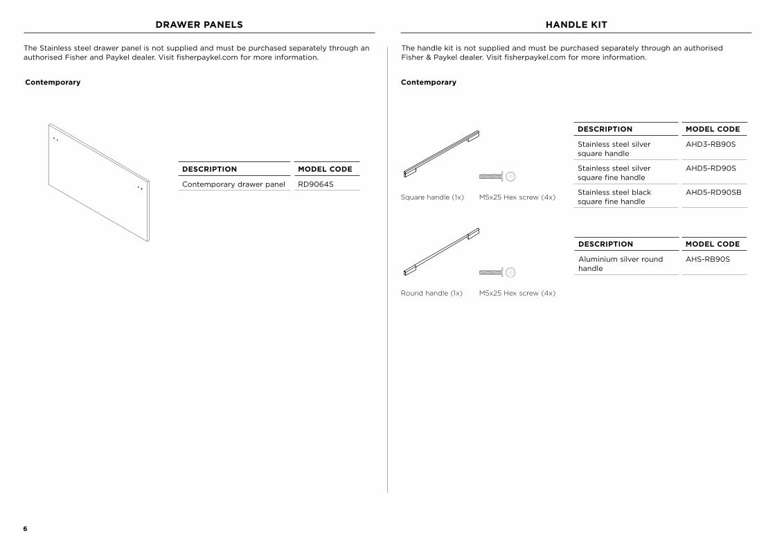
PRODUCT DIMENSIONS
PRODUCT DIMENSIONS MM
A Overall height of product* 640
B Overall width of product* 855
C Depth of chassis** 557
D Width of internal drawer front 805
E Depth of internal drawer front 45
F Depth of drawer (open) measured from front* 520
* Does not include Stainless steel or custom door panel, false panel and handle.
**Includes power terminal.
FRONT VIEW
f e
PROFILE VIEW
A
b
C
e
d
PLAN VIEW

8
STAINLESS STEEL PANEL DIMENSIONS
DRAWER PANEL DIMENSIONSCONTEMPORARY
MM
A Height of custom drawer panel 476
B Width of custom drawer panel 908
C Depth of custom drawer panel 19
Weight of drawer panel (including handle) 7kg
FALSE PANEL DIMENSIONS MM
D Height of custom false panel 150 - 180
E Width of custom false panel min 896
F Depth of custom false panel 16 - 20
False panel to be manufactured and fitted by cabinetmaker. The false panel must be adequately sealed to withstand moisture (50°C @ 80% RH).
CLEARANCE DIMENSIONS MM
G Clearance between top of drawer panel and underside of benchtop
2
H Clearance between front end of benchtop to front surface of drawer panel
max 20
I Gap between drawer panel and false panel 4
J Depth from back of drawer panel/false panel to base of cabinetry
min 40
K Height for ventilation* min 50
* Minimum height to ensure adequate airflow to prevent condensation build up on the floor.
g
H
A
i
d
ISO VIEW
A
b
c
e
d
PROFILE VIEW
K
F
j

9
CUSTOM PANEL DIMENSIONS — SINGLE PANEL
DRAWER PANEL DIMENSIONS MM
A Height of custom drawer panel min 630
B Width of custom drawer panel min 896
C Depth of custom drawer panel 16 - 20
Maximum weight of drawer (including handle) 7 kg
Custom drawer panel to be manufactured and fitted by cabinetmaker. These panels must be adequately sealed to withstand moisture (50°C @ 80% RH).
CLEARANCE DIMENSIONS MM
D Clearance between top of drawer panel and underside of benchtop
2
E Clearance between front end of benchtop to front surface of drawer panel
max 20
F Depth from back of drawer panel/false panel to base of cabinetry
min 40
G Height for ventilation* min 50
* Minimum height to ensure adequate airflow to prevent condensation build up on the floor.
A
A
b
c
PROFILE VIEW
ISO VIEW
f
d
e
g

10
CUSTOM PANEL DIMENSIONS — DUAL PANEL
DRAWER PANEL DIMENSIONS MM
A Height of custom drawer panel min 476
B Width of custom drawer panel min 896
C Depth of custom drawer panel 16 - 20
Weight of drawer panel (including handle) 7kg
FALSE PANEL DIMENSIONS MM
D Height of custom false panel 150 - 180
E Width of custom false panel min 896
F Depth of custom false panel 16 - 20
Custom drawer panel and false panel to be manufactured and fitted by cabinetmaker. These panels must be adequately sealed to withstand moisture (50°C @ 80% RH).w
CLEARANCE DIMENSIONS MM
G Clearance between top of drawer panel and underside of benchtop
2
H Clearance between front end of benchtop to front surface of drawer panel
max 20
I Gap between drawer panel and false panel 4
J Depth from back of drawer panel/false panel to base of cabinetry
min 40
K Height for ventilation* min 50
* Minimum height to ensure adequate airflow to prevent condensation build up on the floor.
A
i
d
PROFILE VIEW
A
b
c
f
e
d
ISO VIEW
g
K
h
j

11
CABINETRY DIMENSIONS — FRAMED
DIMENSIONS MM
A Overall width of cabinetry frame 914
B Inside width of cabinetry frame min 864
C Inside height from top inner face of cabinetry frame to top of spacer*
min 644
D Inside height from top inner face to bottom inner face of cabinetry frame
665 - 764
E Inside depth from front to rear wall of cabinetry min 560
F Height of spacer min 21
G Width of spacer min 50
H Width of vent duct min 215
I Depth of vent duct min 40
J Clearance between vent ducts min 280
K Clearance between vent duct and spacer min 76
L Depth of cutout at front end of internal shelf** min 102
M Width of internal shelf cutout** min 764
N Corner radius of internal shelf cutout Ø 16
* Minimum internal height of cabinetry can be 644mm if vent duct is not used.
** If using internal shelf.
spacer
A
B
C
f
G
iH
j
hk e
D
ISO VIEW
l
n
m
An internal shelf can be used as an alternative to the spacers to position
the drawer at the correct height
ISO VIEW

12
DIMENSIONS MM
A Overall width of cabinetry frame 900
B Inside width of cabinetry frame min 864
C Inside height from top inner face of cabinetry frame to top of spacer*
min 644
D Inside height from top inner face to bottom inner face of cabinetry frame
665 - 764
E Inside depth from front to rear wall of cabinetry min 560
F Height of spacer min 21
G Width of spacer min 50
H Width of vent duct min 215
I Depth of vent duct min 40
J Clearance between vent ducts min 280
K Clearance between vent duct and spacer min 76
L Depth of cutout at front end of internal shelf** min 102
M Width of internal shelf cutout** min 764
N Corner radius of internal shelf cutout Ø 16
* Minimum internal height of cabinetry can be 644mm if vent duct is not used.
** If using internal shelf.
NOTE: The product can also be placed directly on the bottom shelf without the spacer or internal shelf depending on the height of your cabinetry.
CABINETRY DIMENSIONS — FRAMELESS
spacer
A
B
C
f
G
iH
j
hk e
D
l
n
m
An internal shelf can be used as an alternative to the spacers to position
the drawer at the correct height
ISO VIEW
ISO VIEW
13
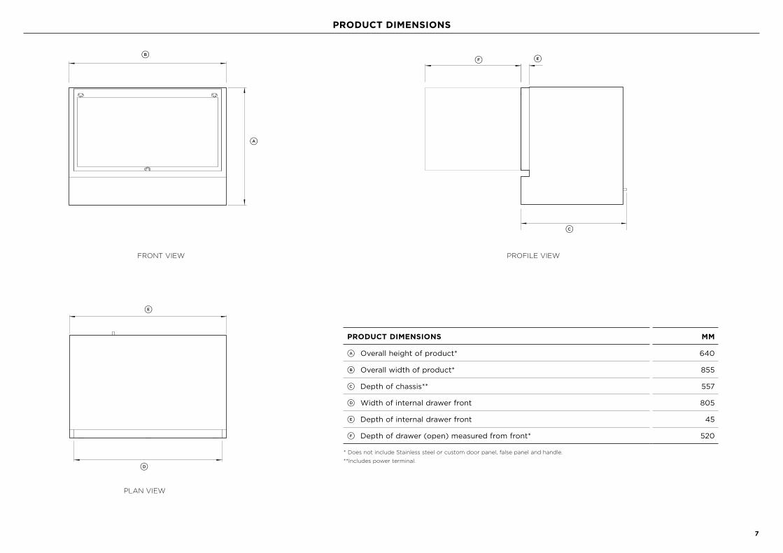
ELECTRICAL CONNECTION
ELECTRICAL SPECIFICATIONS
Supply 230 VAC, 50 Hz
Service 10 amp circuit
Socket 3-pin earthing-type
Total length of power cord 2000mm
Power cord length exiting from left side of product 1850mm
Power cord length exiting from right side of product 1250mm
SUPPLY DIMENSIONS MM
A Diameter of supply area cutout Ø 50
B Distance from centre of supply area cutout to top of spacer
min 130
C Distance from front end of cabinetry frame to centre of supply area cutout
min 535
D Distance of supply area cutout to power outlet max 850
c
b
d
a
Services can be located on either side of the CoolDrawerTM. Disconnect power to surrounding appliances before preparing the cavity.
2000mm 2000mm
1850mm 1250mm

14
CABINETRY PREPARATION
Locate the brackets to the top of each spacer.
Ensure there is 25mm clearance between the front end of cabinetry frame and front of bracket.
Secure each bracket to the spacer with countersunk screws (3x).
Locate the vent ducts to the slots in the cabinetry frame.
Cut each vent duct to be flush with the top of the spacer.
Smooth the sharp edges with a file or similar tool.
Secure the vent ducts by fixing with screws.
1
1
2
3
4
2
INSTALL BRACKETS ATTACH VENT DUCTS
25mm
Screws flushwith bracket

15
Locate the top attachment hooks (2x)in correct orientation to the screw holes at the back of drawer panel*, and secure with screws.
Tighten the locking screw of each hook to 5mm depth.
Attach the handle* to the drawer panel.
Refer to the installation guide included in your purchased handle kit to attach the handle.
1
2
3
STAINLESS STEEL PANEL CUSTOM PANEL
PANEL PREPARATION
Refer to the dimensions below for the preparation of the Custom door panel when attaching the attachment hooks. Drill the screw holes using a 6mm drill bit, and counterbore from the rear.
Refer to stainless steel panel instructions for securing the attachment hooks to the drawer panel. Refer to the installation guide included in your purchased handle kit to attach the handle.
Locate one attachment hook in correct orientation to the screw hole at bottom middle of the back of drawer panel, and secure with screw.
Tighten the locking screw of the hook to 1mm depth.bottom attachment hook
top attachment hook
5mm
1mm
*Illustrations showing Professional drawer panel and handle.
2.5mm
19mm
49.5mm
18mm 18mm
min 896mm
min 710mm
18mm
414
mm
10-42mm

16
Connect the power plug to the back of the CooldrawerTM and clip the cord in place.
Place the CooldrawerTM in front of the cabinetry and connect the power plug to the power outlet.
Slide the CooldrawerTM into the cavity.
Do not screw in the trim brackets at this stage.
Secure the trim brackets with screws to the side of the CooldrawerTM in the correct orientation.
1 1
22
46mm
ATTACH POWER CORD & TRIM BRACKETS POSITION PRODUCT INTO CABINETRY

17
Hook the drawer panel onto the drawer front channel.
Slide the panel to achieve even horizontal clearances.
Close the drawer and check vertical clearances. Open the drawer and clamp the
panel onto the drawer by tightening the bottom attachment hook.
Remove the panel and adjust the top attachment hooks as necesary.
Close the drawer and ensure it is flush with the adjacent cabinetry. If not, the product may have to be pulled back or forward.
Replace the panel on the drawer and confirm vertical clearances.
Ensure there is clearance between the panel and cabinetry when the drawer is fully closed.
1 5
26
3 7
4 8
ATTACH DRAWER PANEL
1/16" (2mm)

18
SECURE PRODUCT TO CABINETRY
ATTACH SIDE TRIMS TO CABINETRY
ATTACH FALSE PANEL
Open the drawer and secure the product to the cabinetry by securing the four trim brackets with screws.
Install the side trims to the trim brackets in the correct orientation.
Attach the false panel securely as recommended by the cabinet maker.
The false panel needs to be removable for servicing.
Check the top and side clearances.
Ensure to check basic operation and complete the final checklist.
1
2
4mm
4mm4mm

19
F Has all packaging been removed from the appliance?
F Is the appliance securely fastened to the cabinetry?
F Does the drawer slide freely and close properly?
F Has the outlet duct been installed correctly?
F Is the appliance level?
F Are the panels securely attached?
F Have the panels been properly aligned for correct operation and appearance? Are all clearances even?
F Is there clearance between drawer and cabinetry frame?
F Has the power cord been plugged into a properly earthed 3-prong outlet, which has been installed in accordance with all applicable electrical codes?
F Is the control panel lit?
F Can you hear the compressor motor running?
F When a hand is placed near the toe kick, can airflow be felt under front right-hand side of appliance?
F Have you demonstrated the basic operation to the customer?
Complete and keep for safe reference:
Model _____________________________________________________________
Serial No. _____________________________________________________________
Purchase Date _____________________________________________________________
Purchaser _____________________________________________________________
Dealer Address _____________________________________________________________
Installer’s Name _____________________________________________________________
Installer’s Signature _____________________________________________________________
Installation Company _____________________________________________________________
Installation Date _____________________________________________________________
FINAL CHECKLIST
TO BE COMPLETED BY THE INSTALLER

FISHERPAYKEL.COM
866530A 02.21
© Fisher & Paykel Appliances 2021. All rights reserved.
The models shown in this guide may not be available in all markets and are subject to change at any time.
The product specifications in this guide apply to the specific products and models described at the date of issue. Under our policy of continuous product
improvement, these specifications may change at any time.
For current details about model and specification availability in your country, please go to our website or contact your local Fisher & Paykel dealer.