Embed Size (px)
Citation preview
uPart014x ilmt PRELIMINARY DATASHEET
uPart014x ilmt 1
Integrate uPart with light, movement, temperature measurement
uPart 014xilmt Device numbers
uPart Family of small wireless sensor nodes 20050827 -MB-P
DESCRIPTION The uPart014xilmt Particle Computer is a ultra -small computing and wireless communication embedded computing system with 4 integrated sensors, one LED actuator and power supply. Usage areas include wireless sensor networks, good supervision and research and education. The uPart is fully integrated in the Particle system and can utilize Particle applications and tools.
FEATURES COMPUTING CORE • Embedded 8-bit Processor: Microchip
12F675 at 4 MHz • Internal Flash 1.4 kByte, Internal SRAM 64
Byte, Internal EEPROM 128 Byte COMMUNICATION • RF Communication: Transmitter (FSK) with
19.2 kBaud bandwidth, 868 MHz European or 315 MHz Japan/US ISM band
• Various RF power version available • Range: up to 30 meters inhouse INTERFACE
• Needle Pinhole interface for rewriting the firmware or to download own firmware
SENSORS AND ACTUATORS • One low power LEDs • High sensitive movement Sensor • Temperature sensor (Microchip TC1047) • Light sensor (Taos TSL13) • Battery voltage sensor POWER SUPPLY • Lithium Coin cell types CR1620, BR1620,
CR1632, BR1632 • Coin cell housing integrated • Battery level measurement • Lifetime: up to several years SOFTWARE AND TOOLS • In circuit configuration using a CRT/LCD
screen without additional hardware • In circuit programming using an optional
programmer • PC based application suite for uPart OVERALL • Outline uPart 0140: 20x17x7 mm • Industrial temperature range (-40 to +85°C)
uPart 014xilmt BLOCK DIAGRAM
to be done
uPart014x ilmt PRELIMINARY DATASHEET
uPart014x ilmt 2
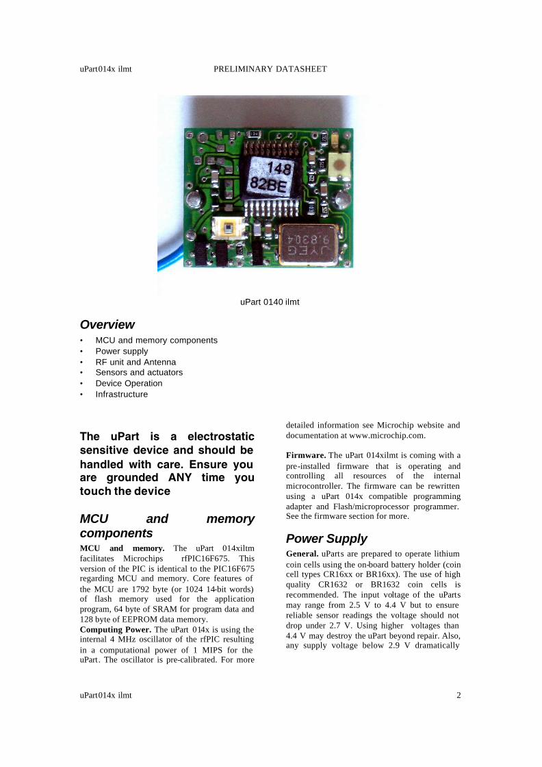
uPart 0140 ilmt
Overview • MCU and memory components • Power supply • RF unit and Antenna • Sensors and actuators • Device Operation • Infrastructure
The uPart is a electrostatic sensitive device and should be handled with care. Ensure you are grounded ANY time you touch the device
MCU and memory components MCU and memory. The uPart 014xiltm facilitates Microchips rfPIC16F675. This version of the PIC is identical to the PIC16F675 regarding MCU and memory. Core features of the MCU are 1792 byte (or 1024 14-bit words) of flash memory used for the application program, 64 byte of SRAM for program data and 128 byte of EEPROM data memory. Computing Power. The uPart 014x is using the internal 4 MHz oscillator of the rfPIC resulting in a computational power of 1 MIPS for the uPart. The oscillator is pre-calibrated. For more
detailed information see Microchip website and documentation at www.microchip.com. Firmware. The uPart 014xilmt is coming with a pre-installed firmware that is operating and controlling all resources of the internal microcontroller. The firmware can be rewritten using a uPart 014x compatible programming adapter and Flash/microprocessor programmer. See the firmware section for more.
Power Supply General. uParts are prepared to operate lithium coin cells using the on-board battery holder (coin cell types CR16xx or BR16xx). The use of high quality CR1632 or BR1632 coin cells is recommended. The input voltage of the uParts may range from 2.5 V to 4.4 V but to ensure reliable sensor readings the voltage should not drop under 2.7 V. Using higher voltages than 4.4 V may destroy the uPart beyond repair. Also, any supply voltage below 2.9 V dramatically
uPart014x ilmt PRELIMINARY DATASHEET
uPart014x ilmt 3
decreases maximum sending range of the devices. The maximum peak current of a 3 V powered Particle is about 14mA in full sending with full field-strength and about 4 mA with low field-strength. Battery lifetime. Note that coin cells are not intended to supply current over 1 mA over a longer period of time. When operating the uPart in high current modes (e.g. long sending range) the use of short sending times and long sleep-times is recommended. Long sleep phases are required to refresh the coin cells when using high peak supply current. Short or no sleep phases will lead to a reduced lifetime of the battery. In case of high current consumption and short sleeping time usable battery capacity may fall below 1% of the nominal battery capacity. Refer to the battery datasheet for more information about the influence on high current consumption on battery life. The table below shows minimal sleeping time values for the use of a uPart with a CR1632 battery. Using these values will lead to several month of operation when using high quality batteries. Operation with CR1632 Recommended minimal sleeping time (s)
RF ouput power (sensors switched on)
0.5 Output Power=-70 dBm, switched off sensors
2 Ouput Pow. = -70 dBm 4 Output Power = -12 dBm 9 Output Power = -4 dBm 36 Output Power = 2 dBm Not recommended Output Power = 9 dBm When using other battery types (uPart Bat extension required) lifetime may increase dramatically. The table below shows a typical configuration with short and long sending range and medium to short sending intervals . Operation with CR2477
Approx. Sleeping time (s)
Approx. Lifetime output power -70dBm
Approx. Lifetime ouput power 2 dBm
2 9 month 1.5 month 4 1.5 years 4 month 9 3 years 1 year 36 12 years 6 years Other type of power supply. The uPart can also be operated using other type of power supplies. All power supplies should ensure a minimal working voltage level of 2.9 V and a maximum voltage of 4.4 V and should be able to deliver the required current needed for your uPart configuration. See the Electrical Characteristics in the Appendix for more detail Battery voltage measurement. The uPart is able to measure its own battery level using a on-board voltage reference. When using the default Firmware the voltage level is sent together with the sensor values. This information can be analyzed and used by either the standard Particle firmware (e.g. the Particle Analyzer) or by a user program.
Sensors and Actuators Three sensors and one actuator are integrated at the uPart 014x: A light sensor, a temperature sensor, a motion sensor and a LED. The position of sensors and actuator an be seen at the layout (component side) at the appendix of this datasheet. Light sensor. The TSL13T from Taos Inc. is used as light sensor. The sensor is a mid -sensitive analog light sensor with a linear output voltage of 24 mV/(µW/cm²) at λ = 640 nm. The highest sensitivity of the sensor is about 750 nm, but good sensitivity (>50%) can be obtain from a spectrum between 550 nm and 900 nm. The TSL13T covers a total spectrum between 320 nm and 1050 nm. The TSL13T is most sensitive for light directed towards the sensor (0°). The sensitivity drops slightly when light is directed with larger angles. 50% sensitivity can be obtained between -70 and +70° angular displacement of sensor and light beam. See also the datasheet of the TSL13T at www.taosinc.com for more detail. Temperature Sensor. The TC1047A temperature to voltage converter from Microchip is used as a temperature sensor. The sensor is specified for ±0.5°C accuracy (typ.) with a linear temperature slope of 10 mV/°C and a total operating temperature of -40°C to +125 °C. See also the datasheet of the TC1047A at www.microchip.com for more detail.
uPart014x ilmt PRELIMINARY DATASHEET
uPart014x ilmt 4
Motion sensor. The motion sensor is a (digital) micro -maschined ball-switch sensor. The function principle of the ball switch sensor is a tiny golden ball that is rolling up and down the miniature space inside the ball-switch. Detection is done by detecting the balls contact on each side of the ball switch. The ball switch is very sensitive to even slightest movement or vibration if used with component side upwards. When the uPart is tilted so that the component side is not absolutely horizontal sensitivity is reduced. If the uPart is tilted more than 90° so that the battery side is showing upwards, the movement sensors sensitivity degrades to 0. The output of the motion sensor is in principle either GND or VDD dependent on the position of the ball inside the sensor. Due to its high sensitivity, in practice movement of the ball-switch may be so fast that unloading the capacity from one state at the MCUs port - where the ball-switch is connected to - is not finished before the next state of the ball-switch is reached. Care should be taken that such analog intermediate states do not influence proper function of the MCU, e.g. while operating with enabled interrupts. Actuators . For notification and debugging the uPart provides a low-power LED (bright red) as an actuator. The LED port is connected to the enable/disable power supply pin for sensors and RF-communication. This means that the LED is switched on when the RF-Communication part of the uPart is activated and vice versa. Connection of Sensors and actuator to MCU. The below table shows the connection of the sensors to the MCU of the uPart. Connection of sensors/act. to MCU Sensor name
Port at RFPIC12F675
Voltage Port1 / Analog Port 1 Temperature Port2 / Analog Port 2 Movement Port3 Light Port4/ Analog Port 3 LED Port 5 Power supply of sensors and actuators . All sensors except the ball-switch and the voltage measurement are connected to a switchable power-line. This way the application program can conserve energy by switching off the sensors when they are not in operation. The
power-line is multiplexed with the power supply of the RF communication component of the uPart. Switching on the sensors automatically switches off the RF part and vice versa. Sensors can also be switched off when the RF part is switched off by switching off an additional port (Port 0). Therefore sensors on the uPart are powered up if and only if the following preconditions apply: Port 0 must be high AND Port 5 must be low. To allow continuous monitoring motion sensor and voltage reference diode are continuously powered up. The following table shows the power consumption for the sensors used Power consumption of sensors
Sensor name Typ (mA at 3V)
Max (mA at 3V)
Voltage 0.01 0.015 Temperature 0.035 0.065 Movement 0.001 0.002 Light 1.1 1.7 LED 1* 1.5*
RF and communication General. The uPart 014x is a RF transmit-only sensor node. This means that sensor data can be transmitted to another sensor node or another computing or infrastructure device, but there is no way to receive information from other computers via radio frequency communication. As a consequence, any data transmitted from a uPart sensor node can not be acknowledged and therefore there is no guarantee that transmitted information is received. Smart application program design can overcome this problem. RF Unit. The uPart contains an integrated RF unit, a wire antenna and matched components. FSK modulation is chosen. For more information about the RF unit see the datasheet of the RFPIC12F675 at www.microchip.com. There are two frequencies available so far: 314.8896 MHz for the use in the Japan/USA 315 MHz ISM band and 869.89 MHz for the use in the European 868 ISM band (center frequencies). The 868 MHz band frequency is selected to comply to the regulation CEPT/ERC Rec 70-03 for operation with 100% duty cycle (continuously sending).
uPart014x ilmt PRELIMINARY DATASHEET
uPart014x ilmt 5
RF Power . The sending power of the uPart is regulated via resistor R4 (see figure of the component side at the appendix). By choosing the appropriate resistor the sending field strength of the uPart is selected. See table ?? in the appendix for more information about the resistor value, sending fieldstrength, communication range and RF power consumption. Antenna. The antenna implemented on the uPart is a wire antenna (Type DEF61-12 (Part 6) Type 2) with the following length: Antenna length
Frequency Band
Length (cm)
315 MHz 21.8 868 MHz 9 Best performance can be gained by having the antenna standing in upright position (90°) on the PCB. In any case, the antenna should be directed away from the PCB. Bending the antenna may decrease communication range.
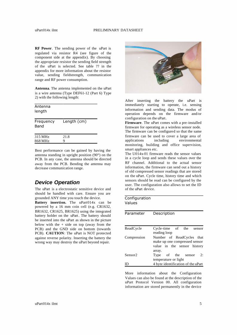
Device Operation The uPart is a electrostatic sensitive device and should be handled with care. Ensure you are grounded ANY time you touch the device. Battery insertion. The uPart014x can be powered by a 16 mm coin cell (e.g. CR1632, BR1632, CR1625, BR1625) using the integrated battery holder on the uPart . The battery should be inserted into the uPart as shown in the picture below with the + side on top (away from the PCB) and the GND side on bottom (towards PCB). CAUTION : The uPart is NOT protected against reverse polarity. Inserting the battery the wrong way may destroy the uPart beyond repair.
After inserting the battery the uPart is immediately starting to operate, i.e. sensing information and sending data. The modus of operation depends on the firmware and/or configuration on the uPart. Firmware. The uPart comes with a pre-installed firmware for operating as a wireless sensor node. The firmware can be configured so that the same firmware can be used to cover a large area of applications including environmental monitoring, building and office supervision, smart appliances etc. The U014x-01 firmware reads the sensor values in a cycle loop and sends these values over the RF channel. Additional to the actual sensor information, the firmware can send out a history of old compressed sensor readings that are stored on the uPart. Cycle time, history time and which sensors should be read can be configured by the user. The configuration also allows to set the ID of the uPart device. Configuration Values
Parameter Description
ReadCycle Cycle-time of the sensor reading loop
Compression Number of ReadCycles that make up one compressed sensor value in the sensor historyarray.
Sensor2 Type of the sensor 2: temperature or light
ID 4 byte identification of the uPart More information about the Configuration Values can also be found at the description of the uPart Protocol Version 00. All configuration information are stored permanently in the device
uPart014x ilmt PRELIMINARY DATASHEET
uPart014x ilmt 6
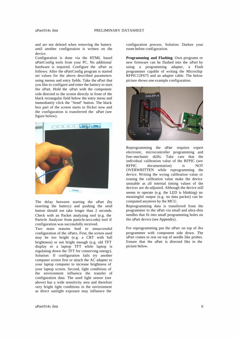
and are not deleted when removing the battery until another configuration is written on the device. Configuration is done via the HTML based uPartConfig tools from your PC. No additional hardware is required. Configure the uPart as follows: After the uPartConfig program is started set values for the above described parameters using menus and entry fields. Take the uPart that you like to configure and enter the battery to start the uPart. Hold the uPart with the component side directed to the screen directly in front of the black rectangular field below the entry menu and immediately click the "Send" button. The black box part of the screen starts to flicker now and the configuration is transferred the uPart (see figure below).
The delay between starting the uPart (by inserting the battery) and pushing the send button should not take longer than 2 seconds. Check with an Packet analyzing tool (e.g. the Particle Analyzer from particle.teco.edu) tool if configuration was successfully received. Two main reasons lead to unsuccessful configuration of the uParts. First, the screen used may be too bright (e.g. a CRT with full brightness) or not bright enough (e.g. old TFT display or a laptop TFT while laptop is regulating down the TFT for conserving energy). Solution: If configuration fails try another computer screen first or attach the AC adapter to your laptop computer to increase brightness of your laptop screen. Second, light conditions of the environment influence the transfer of configuration data. The used light sensor (see above) has a wide sensitivity area and therefore very bright light conditions in the environment as direct sunlight exposure may influence the
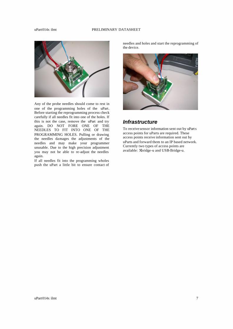
configuration process. Solution: Darken your room before configuration. Programming and Flashing. Own programs or new firmware can be flashed into the uPart by using a programming adapter, a Flash programmer capable of writing the Microchip RFPIC12F675 and an adapter cable. The below picture shows one example configuration.
Reprogramming the uPart requires expert electronic, microcontroller programming and fine-mechanic skills. Take care that the individual calibration value of the RFPIC (see RFPIC documentation) is NOT OVERWRITTEN while reprogramming the device. Writing the wrong calibration value or erasing the calibration value make the device unusable as all internal timing values of the devices are de-adjusted. Although the device still seems to operate (e.g. the LED is blinking) no meaningful output (e.g. no data packet) can be computed anymore by the MCU. Reprogramming data is transferred from the programmer to the uPart via small and ultra-thin needles that fit into small programming holes on the uPart device (see Appendix). For reprogramming put the uPart on top of the programmer with component side down. The uPart comes to rest on top of needle like probes. Ensure that the uPart is directed like in the picture below.
uPart014x ilmt PRELIMINARY DATASHEET
uPart014x ilmt 7
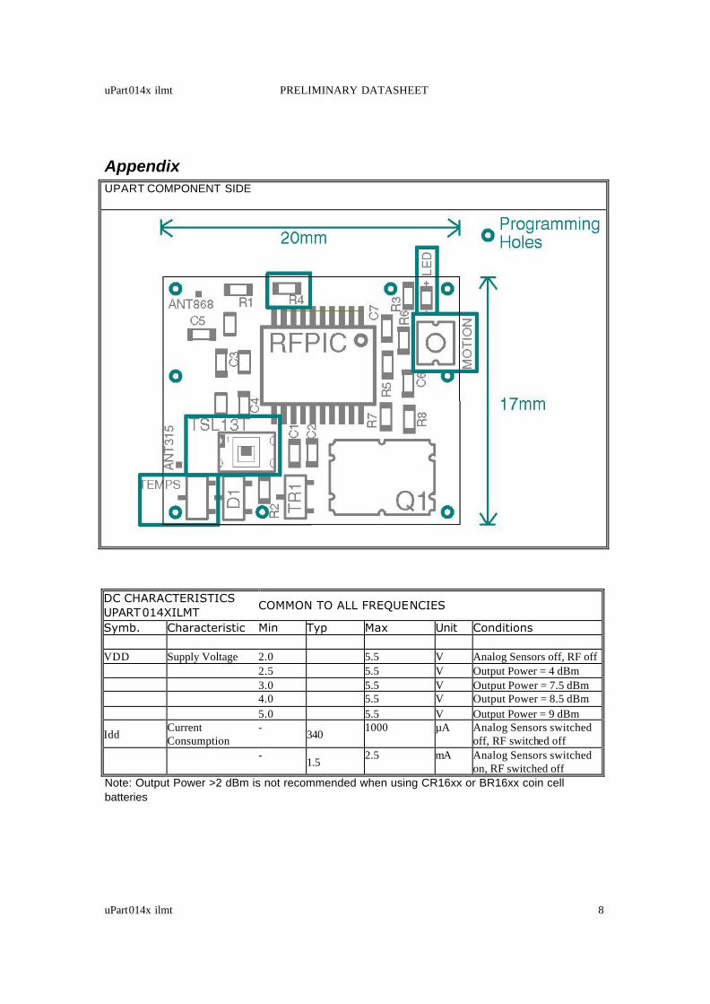
Any of the probe needles should come to rest in one of the programming holes of the uPart. Before starting the reprogramming process check carefully if all needles fit into one of the holes. If this is not the case, remove the uPart and try again. DO NOT FORE ONE OF THE NEEDLES TO FIT INTO ONE OF THE PROGRAMMING HOLES. Pulling or drawing the needles damages the adjustments of the needles and may make your programmer unusable. Due to the high precision adjustment you may not be able to re-adjust the needles again. If all needles fit into the programming wholes push the uPart a little bit to ensure contact of
needles and holes and start the reprogramming of the device.
Infrastructure To receive sensor information sent out by uPart s access points for uParts are required. These access points receive information sent out by uParts and forward them to an IP based network. Currently two types of access points are available: Xbridge-u and USB-Bridge-u.
uPart014x ilmt PRELIMINARY DATASHEET
uPart014x ilmt 8
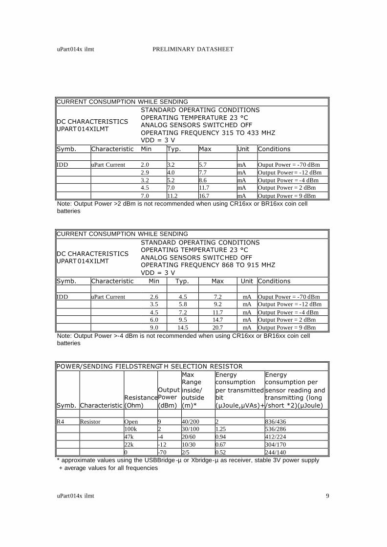
Appendix UPART COMPONENT SIDE
DC CHARACTERISTICS UPART014XILMT
COMMON TO ALL FREQUENCIES
Symb. Characteristic Min Typ Max Unit Conditions VDD Supply Voltage 2.0 5.5 V Analog Sensors off, RF off 2.5 5.5 V Output Power = 4 dBm 3.0 5.5 V Output Power = 7.5 dBm 4.0 5.5 V Output Power = 8.5 dBm 5.0 5.5 V Output Power = 9 dBm
Idd Current Consumption
- 340
1000 µA Analog Sensors switched off, RF switched off
-
1.5 2.5 mA Analog Sensors switched
on, RF switched off Note: Output Power >2 dBm is not recommended when using CR16xx or BR16xx coin cell batteries
uPart014x ilmt PRELIMINARY DATASHEET
uPart014x ilmt 9
CURRENT CONSUMPTION WHILE SENDING
DC CHARACTERISTICS UPART014XILMT
STANDARD OPERATING CONDITIONS OPERATING TEMPERATURE 23 °C ANALOG SENSORS SWITCHED OFF OPERATING FREQUENCY 315 TO 433 MHZ VDD = 3 V
Symb. Characteristic Min Typ. Max Unit Conditions IDD uPart Current 2.0 3.2 5.7 mA Ouput Power = -70 dBm 2.9 4.0 7.7 mA Output Power = -12 dBm 3.2 5.2 8.6 mA Output Power = -4 dBm 4.5 7.0 11.7 mA Output Power = 2 dBm 7.0 11.2 16.7 mA Output Power = 9 dBm Note: Output Power >2 dBm is not recommended when using CR16xx or BR16xx coin cell batteries CURRENT CONSUMPTION WHILE SENDING
DC CHARACTERISTICS UPART014XILMT
STANDARD OPERATING CONDITIONS OPERATING TEMPERATURE 23 °C ANALOG SENSORS SWITCHED OFF OPERATING FREQUENCY 868 TO 915 MHZ VDD = 3 V
Symb. Characteristic Min Typ. Max Unit Conditions IDD uPart Current 2.6 4.5 7.2 mA Ouput Power = -70 dBm 3.5 5.8 9.2 mA Output Power = -12 dBm 4.5 7.2 11.7 mA Output Power = -4 dBm 6.0 9.5 14.7 mA Output Power = 2 dBm 9.0 14.5 20.7 mA Output Power = 9 dBm Note: Output Power >-4 dBm is not recommended when using CR16xx or BR16xx coin cell batteries POWER/SENDING FIELDSTRENGT H SELECTION RESISTOR
Symb. Characteristic Resistance (Ohm)
Output Power (dBm)
Max Range inside/ outside (m)*
Energy consumption per transmitted bit (µJoule,µVAs)+
Energy consumption per sensor reading and transmitting (long /short *2)(µJoule)
R4 Resistor Open 9 40/200 2 836/436 100k 2 30/100 1.25 536/286 47k -4 20/60 0.94 412/224 22k -12 10/30 0.67 304/170 0 -70 2/5 0.52 244/140 * approximate values using the USBBridge -µ or Xbridge-µ as receiver, stable 3V power supply + average values for all frequencies
uPart014x ilmt PRELIMINARY DATASHEET
uPart014x ilmt 10
*2 long packet: 400 bits including preamble, short packet 200 bits including preamble. Sensor reading and computation power consumption 36 µJ for reading all 3 sensors and reading the battery voltage (including ramp-up of sens ors: 3,5 ms), computing time (0.5 ms) and performing one additional EEPROM writing operations (4ms)
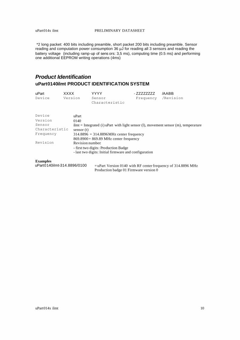
Product Identification uPart0140ilmt PRODUCT IDENTIFICATION SYSTEM uPart XXXX YYYY - ZZZZZZZZ /AABB Device Version Sensor Frequency /Revision Characteristic Device uPart Version 0140 Sensor Characteristic
ilmt = Integrated (i) uPart with light sensor (l), movement sensor (m), temperature sensor (t)
Frequency 314.8896 = 314.8896 MHz center frequency 869.8900 = 869.89 MHz center frequency
Revision Revision number: - first two digits: Production Badge - last two digits: Initial firmware and configuration
Examples uPart0140ilmt-314.8896/0100 = uPart Version 0140 with RF center frequency of 314.8896 MHz
Production badge 01 Firmware version 0