Embed Size (px)
Citation preview
Integrable Optics Test Accelerator
Sergei NagaitsevFermilab
April 3, 2013
Background and History• In 2006, Fermilab was asked to lead the US ILC/SRF R&D Program
we felt that the most effective way to do that was to learn by doing
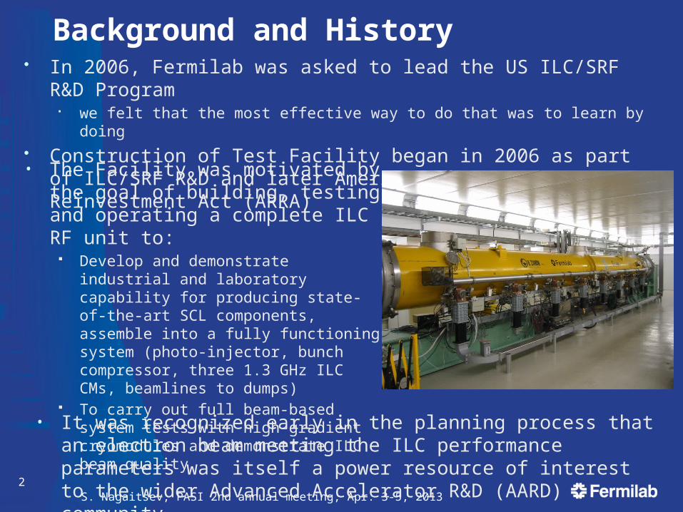
• Construction of Test Facility began in 2006 as part of ILC/SRF R&D and later American Recovery and Reinvestment Act (ARRA)
2S. Nagaitsev, PASI 2nd annual meeting, Apr. 3-5, 2013
• It was recognized early in the planning process that an electron beam meeting the ILC performance parameters was itself a power resource of interest to the wider Advanced Accelerator R&D (AARD) community
• The Facility was motivated by the goal of building, testing and operating a complete ILC RF unit to:
Develop and demonstrate industrial and laboratory capability for producing state-of-the-art SCL components, assemble into a fully functioning system (photo-injector, bunch compressor, three 1.3 GHz ILC CMs, beamlines to dumps)
To carry out full beam-based system tests with high-gradient cryomodules and demonstrate ILC beam quality
Background and History• In planning the construction we therefore wanted to ensure that the
facility offered something of enduring value when it was completed. Hence, the investment in establishing a flexible facility that would readily
support an AARD user program.• For those reasons the ARRA-funded facility construction
incorporated space for additional ILC cryomodules to increase the beam energy to 1.5 GeV, space for multiple high-energy beamlines, space for a small circular ring for the exploration of advanced concepts, capability of transporting laser light into and out of the accelerator enclosure, an adequately-sized control room
• To date, an investment of $74M has been made, including $18M of ARRA funding, representing ~80% completion of the facility
• In June 2012, anticipating the completion of the ILC R&D Program, Fermilab was directed to prepare a proposal for the AARD program.
Proposal submitted to the DOE in Feb 2013
3 S. Nagaitsev, PASI 2nd annual meeting, Apr. 3-5, 2013
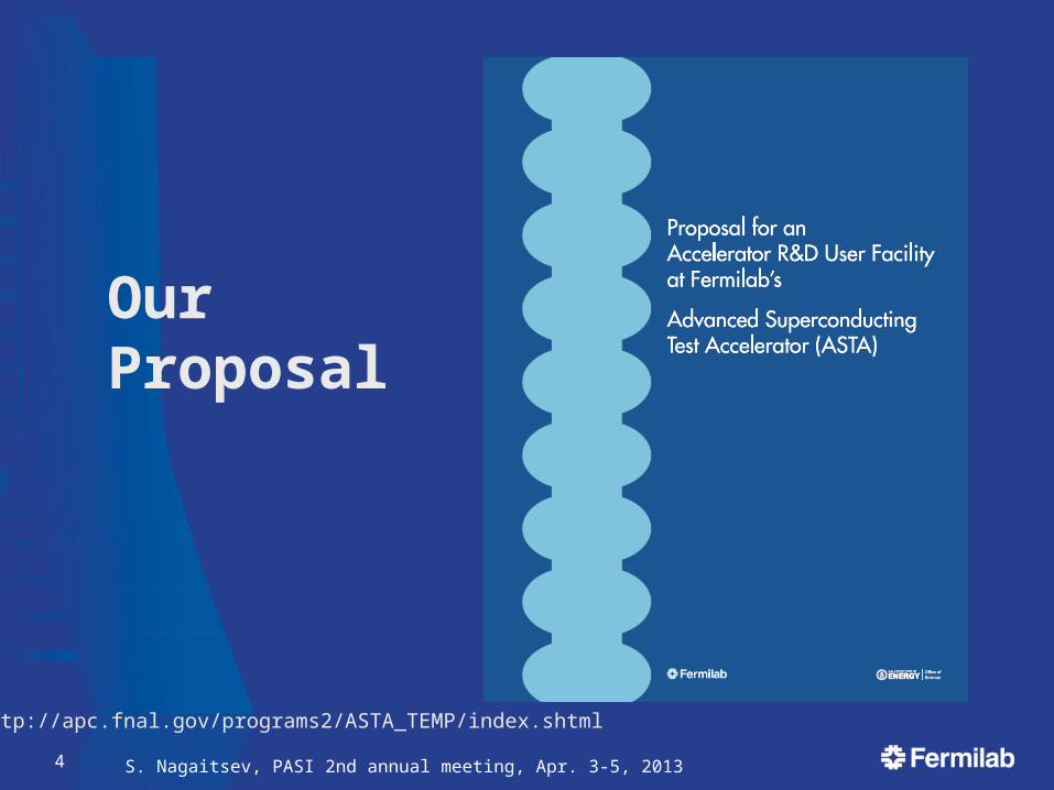
Our Proposal
4 S. Nagaitsev, PASI 2nd annual meeting, Apr. 3-5, 2013
http://apc.fnal.gov/programs2/ASTA_TEMP/index.shtml
We proposed to establish a proposal-driven Accelerator R&D User Facility at Fermilab’s Advanced Superconducting Test Accelerator (ASTA)
To do that requires:1. Supporting the completion of ASTA in a phased approach:
Build out the linear accelerator to ~800 MeV with three Cryomodules • associated beam transport lines, dumps and support systems
Construct the Integrable Optics Test Accelerator (IOTA)• A small, flexible storage ring to investigate beam dynamics of importance to
intensity frontier rings In further phases
• Add proton capability to IOTA (by reusing existing HINS equipment)• Increase peak current of compressed electron bunches by installation of 3.9
GHz system
2. Supporting the Operation of an Accelerator R&D User Program Support staff required to operate a 9 month/year proposal-driven
Accelerator R&D program
5 S. Nagaitsev, PASI 2nd annual meeting, Apr. 3-5, 2013
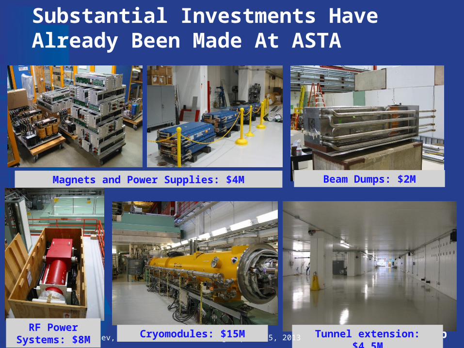
Substantial Investments Have Already Been Made At ASTA
6 Tunnel extension: $4.5M
Beam Dumps: $2MMagnets and Power Supplies: $4M
S. Nagaitsev, PASI 2nd annual meeting, Apr. 3-5, 2013RF Power
Systems: $8MCryomodules: $15M
7 S. Nagaitsev, PASI 2nd annual meeting, Apr. 3-5, 2013
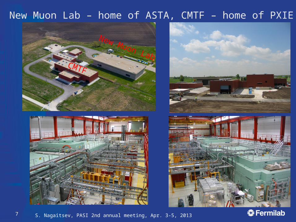
New Muon LabCMTF
New Muon Lab – home of ASTA, CMTF – home of PXIE
S. Nagaitsev, PASI 2nd annual meeting, Apr. 3-5, 20138
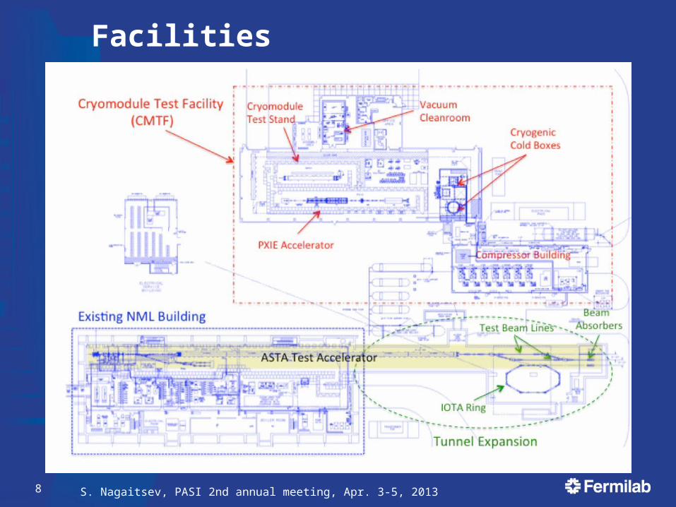
Facilities
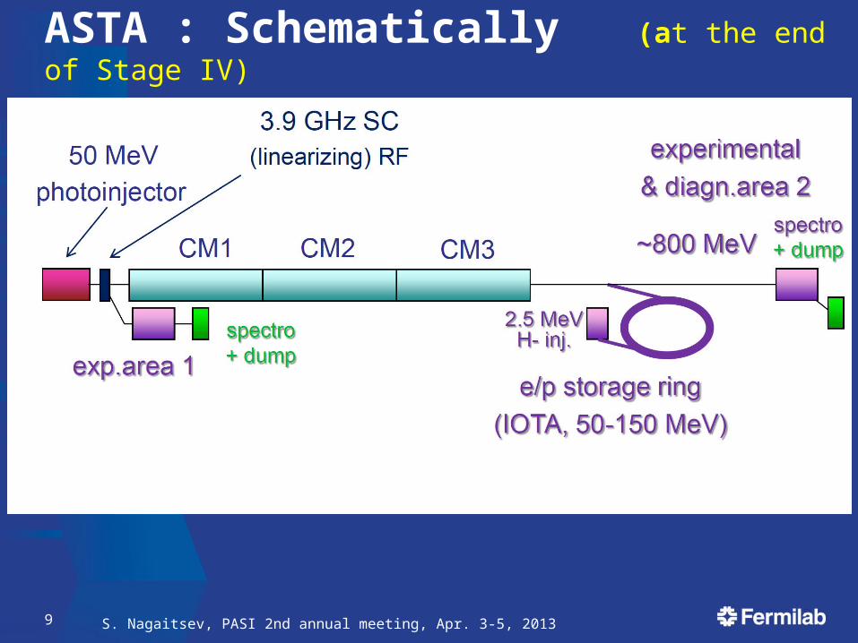
ASTA : Schematically (at the end of Stage IV)
S. Nagaitsev, PASI 2nd annual meeting, Apr. 3-5, 20139
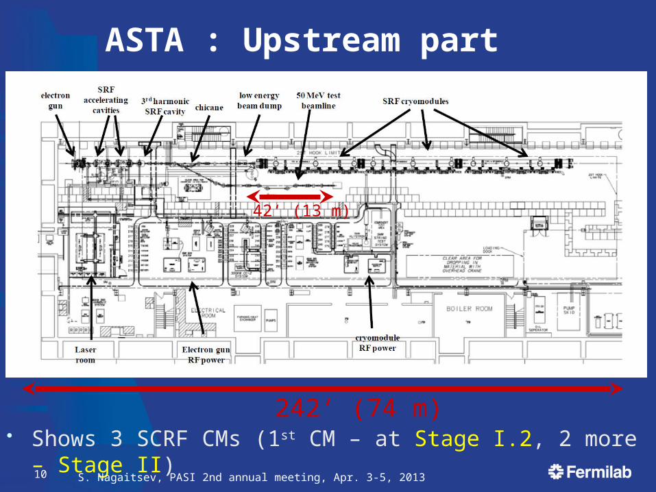
ASTA : Upstream part
• Shows 3 SCRF CMs (1st CM – at Stage I.2, 2 more – Stage II)
S. Nagaitsev, PASI 2nd annual meeting, Apr. 3-5, 201310
242‘ (74 m)
42‘ (13 m)
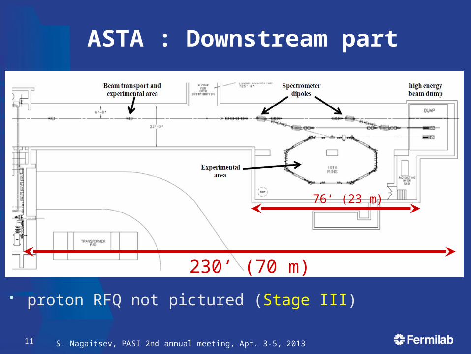
ASTA : Downstream part
• proton RFQ not pictured (Stage III)
S. Nagaitsev, PASI 2nd annual meeting, Apr. 3-5, 201311
230‘ (70 m)
76‘ (23 m)
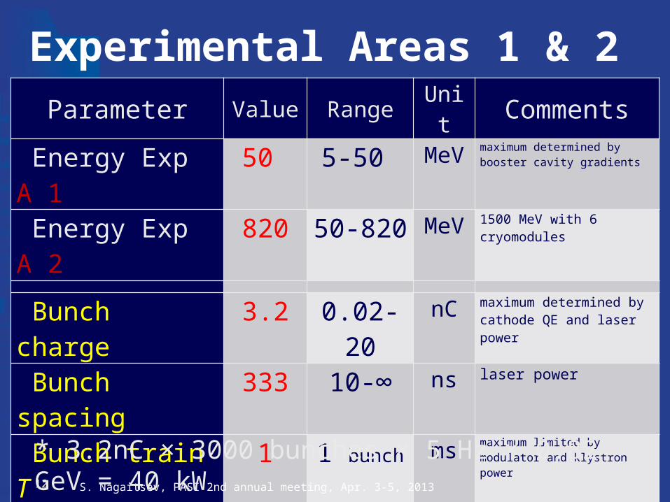
Experimental Areas 1 & 2Parameter Value Range Unit Comments
Energy Exp A 1 50 5-50 MeV maximum determined by booster cavity gradients
Energy Exp A 2 820 50-820 MeV 1500 MeV with 6 cryomodules
Bunch charge 3.2 0.02-20 nC maximum determined by cathode QE and laser power
Bunch spacing 333 10-∞ ns laser power
Bunch train T 1 1 bunch ms maximum limited by modulator and klystron power
Train rep rate 5 0.1-5 Hz minimum may be determined by egun T-regulation and stability considerations
Emittance rms norm 5 <1 … >100 π m maximum limited by aperture and beam losses
Bunch length rms 1 0.01-10 ps min obtained with Ti:Sa laser; maximumobtained with laser pulse stacking
Peak current 3 >9 kA 3 kA with low energy bunch compressor; 9 kA possible with 3.9 GHz linearizing cavity
S. Nagaitsev, PASI 2nd annual meeting, Apr. 3-5, 201312
* 3.2nC × 3000 bunches × 5 Hz × 0.82 GeV = 40 kW
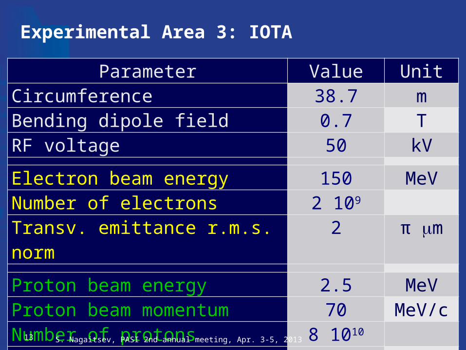
Experimental Area 3: IOTA
Parameter Value UnitCircumference 38.7 mBending dipole field 0.7 TRF voltage 50 kV
Electron beam energy 150 MeVNumber of electrons 2 109
Transv. emittance r.m.s. norm 2 π m
Proton beam energy 2.5 MeVProton beam momentum 70 MeV/cNumber of protons 8 1010
Transv. emittance r.m.s. norm 0.1-0.2 π m
S. Nagaitsev, PASI 2nd annual meeting, Apr. 3-5, 201313
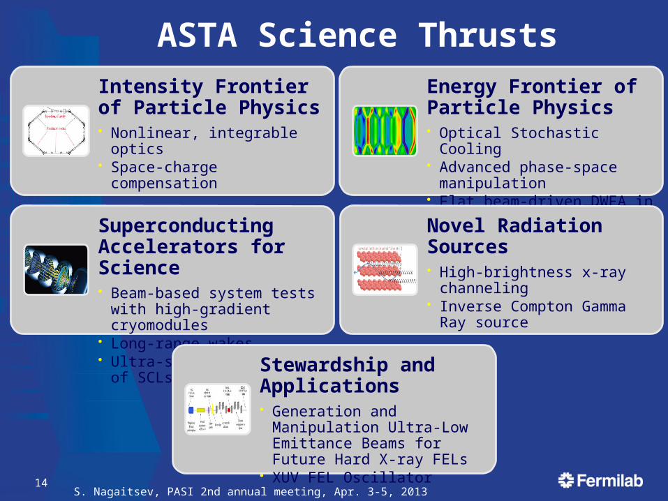
ASTA Science ThrustsIntensity Frontier of Particle Physics• Nonlinear, integrable optics• Space-charge compensation
14
Energy Frontier of Particle Physics• Optical Stochastic Cooling• Advanced phase-space
manipulation• Flat beam-driven DWFA in slabs
Superconducting Accelerators for Science• Beam-based system tests with
high-gradient cryomodules• Long-range wakes• Ultra-stable operation of SCLs
Novel Radiation Sources• High-brightness x-ray channeling• Inverse Compton Gamma Ray
source
Stewardship and Applications• Generation and Manipulation
Ultra-Low Emittance Beams for Future Hard X-ray FELs
• XUV FEL Oscillator
S. Nagaitsev, PASI 2nd annual meeting, Apr. 3-5, 2013
Intensity Frontier• Proposal: Experimental demonstration of integrable
optics lattice at IOTA FNAL, SNS, JINR, Budker INP, BNL, JAI, U. of Colorado, U. of
Chicago
• Proposal: Space Charge Compensation in High Intensity Circular Accelerators
FNAL, support from CERN, BNL
• Experiments require the IOTA Ring Difficult to implement needed linear optics in existing facilities Lack of ring facilities in the US
S. Nagaitsev, PASI 2nd annual meeting, Apr. 3-5, 201315
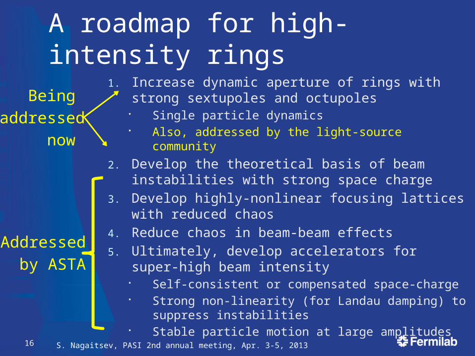
A roadmap for high-intensity rings
1. Increase dynamic aperture of rings with strong sextupoles and octupoles
Single particle dynamics Also, addressed by the light-source community
2. Develop the theoretical basis of beam instabilities with strong space charge
3. Develop highly-nonlinear focusing lattices with reduced chaos
4. Reduce chaos in beam-beam effects
5. Ultimately, develop accelerators for super-high beam intensity
Self-consistent or compensated space-charge Strong non-linearity (for Landau damping) to suppress
instabilities Stable particle motion at large amplitudes
S. Nagaitsev, PASI 2nd annual meeting, Apr. 3-5, 201316
Addressed
by ASTA
Being
addressed
now
S. Nagaitsev, PASI 2nd annual meeting, Apr. 3-5, 201317
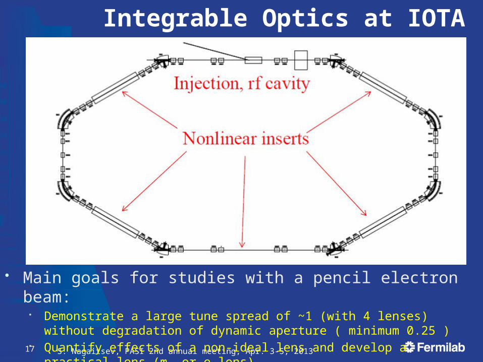
Integrable Optics at IOTA
• Main goals for studies with a pencil electron beam: Demonstrate a large tune spread of ~1 (with 4 lenses) without degradation of
dynamic aperture ( minimum 0.25 ) Quantify effects of a non-ideal lens and develop a practical lens (m- or e-lens)
S. Nagaitsev, PASI 2nd annual meeting, Apr. 3-5, 201318
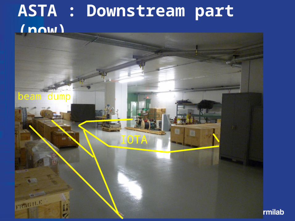
ASTA : Downstream part (now)
beam dump
IOTA
S. Nagaitsev, PASI 2nd annual meeting, Apr. 3-5, 201319
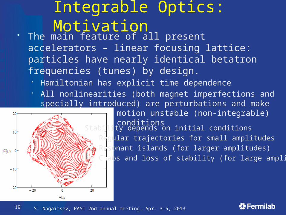
Integrable Optics: Motivation• The main feature of all present accelerators – linear
focusing lattice: particles have nearly identical betatron frequencies (tunes) by design.
Hamiltonian has explicit time dependence All nonlinearities (both magnet imperfections and specially
introduced) are perturbations and make single particle motion unstable (non-integrable) due to resonant conditions
Stability depends on initial conditions
Regular trajectories for small amplitudes
Resonant islands (for larger amplitudes)
Chaos and loss of stability (for large amplitudes)
S. Nagaitsev, PASI 2nd annual meeting, Apr. 3-5, 201320
Does Focusing Need to be Linear?
• Are there “magic” nonlinearities with zero resonance strength?
• The answer is – yes (we call them “integrable”)• Search for a lattice design that is strongly nonlinear yet
stable Orlov (1963) -- attempt failed (non-integrable) McMillan (1967) – first successfull 1-D example Perevedentsev, Danilov (1990 - 1995) – several 1D, 2D examples Cary and colleagues (1994) – approximate integrability
• Our goal (with IOTA) is to create practical nonlinear accelerator focusing systems with a large frequency spread and stable particle motion.
Danilov, Nagaitsev, Phys. Rev. ST Accel. Beams 13, 084002 (2010)
S. Nagaitsev, PASI 2nd annual meeting, Apr. 3-5, 201321
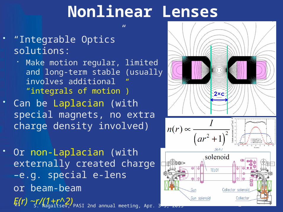
Nonlinear Lenses
• “Integrable Optics” solutions: Make motion regular, limited and long-
term stable (usually involves additional “integrals of motion”)
• Can be Laplacian (with special magnets, no extra charge density involved)
• Or non-Laplacian (with externally created charge –e.g. special e-lens
or beam-beam
E(r) ~r/(1+r^2)
• Both types will be tested in IOTA
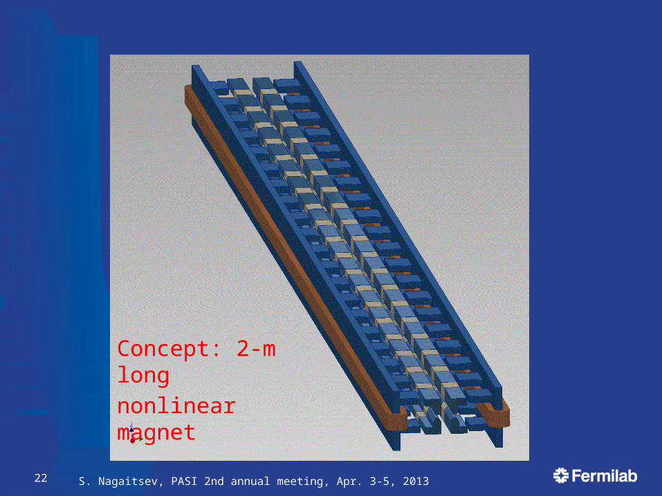
S. Nagaitsev, PASI 2nd annual meeting, Apr. 3-5, 201322
Concept: 2-m long
nonlinear magnet
S. Nagaitsev, PASI 2nd annual meeting, Apr. 3-5, 201323
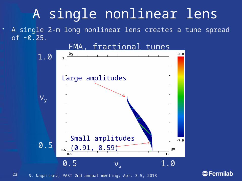
A single nonlinear lens• A single 2-m long nonlinear lens creates a tune spread of ~0.25.
FMA, fractional tunes
Small amplitudes
(0.91, 0.59)
Large amplitudes
0.5 1.0
0.5
1.0
νx
νy
S. Nagaitsev, PASI 2nd annual meeting, Apr. 3-5, 201324
Sys
tem
: lin
ear
FO
FO
; 100
A;
linea
r K
V w
/ mis
mat
ch
Res
ult:
qui
ckly
dri
ves
test
-par
ticle
s in
to th
e ha
lo
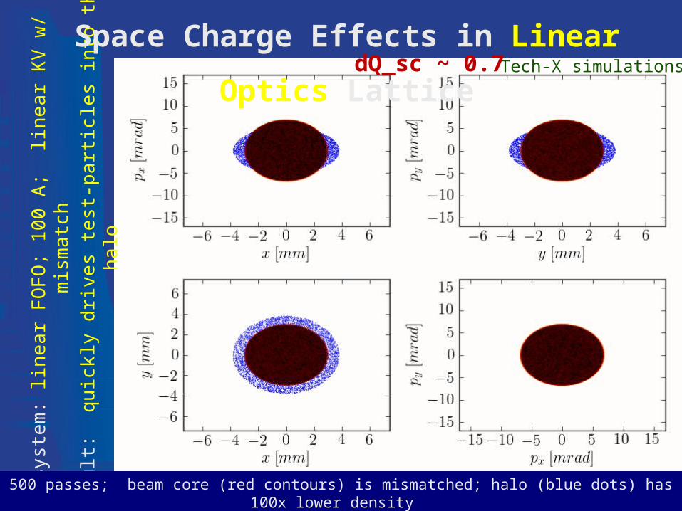
500 passes; beam core (red contours) is mismatched; halo (blue dots) has 100x lower density
Space Charge Effects in Linear Optics LatticeTech-X simulationsdQ_sc ~ 0.7
S. Nagaitsev, PASI 2nd annual meeting, Apr. 3-5, 201325
Sys
tem
: oc
tupo
les;
100
A;
gene
raliz
ed K
V w
/ mis
mat
ch
Res
ult:
non
linea
r de
cohe
renc
e su
ppre
sses
hal
o
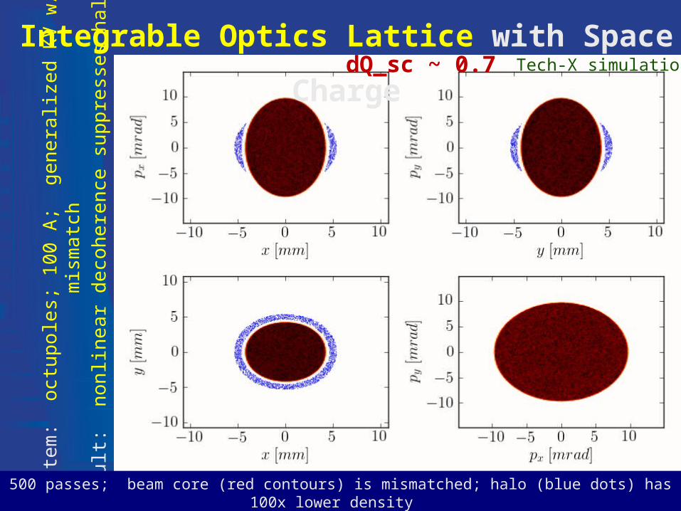
500 passes; beam core (red contours) is mismatched; halo (blue dots) has 100x lower density
Integrable Optics Lattice with Space ChargedQ_sc ~ 0.7 Tech-X simulations
S. Nagaitsev, PASI 2nd annual meeting, Apr. 3-5, 201326
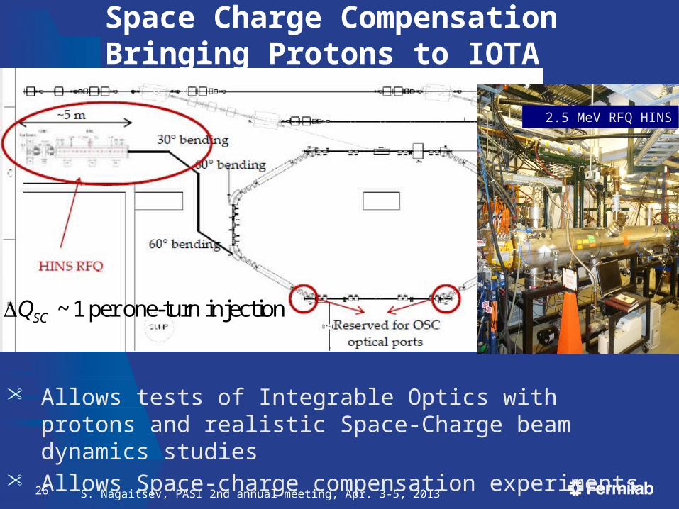
Space Charge CompensationBringing Protons to IOTA
• Allows tests of Integrable Optics with protons and realistic Space-Charge beam dynamics studies
• Allows Space-charge compensation experiments
~ 1 per one-turn injectionSCQ
2.5 MeV RFQ HINS
S. Nagaitsev, PASI 2nd annual meeting, Apr. 3-5, 201327
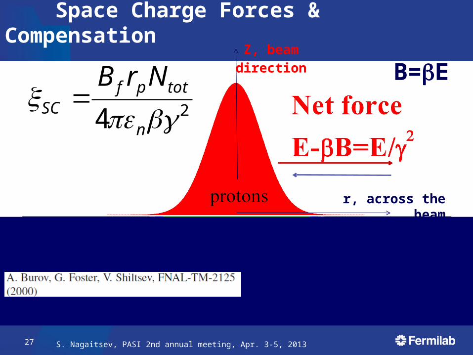
Space Charge Forces & Compensation
24
n
totpfSC
NrB
B=EZ, beam
direction
r, across the beam
S. Nagaitsev, PASI 2nd annual meeting, Apr. 3-5, 201328
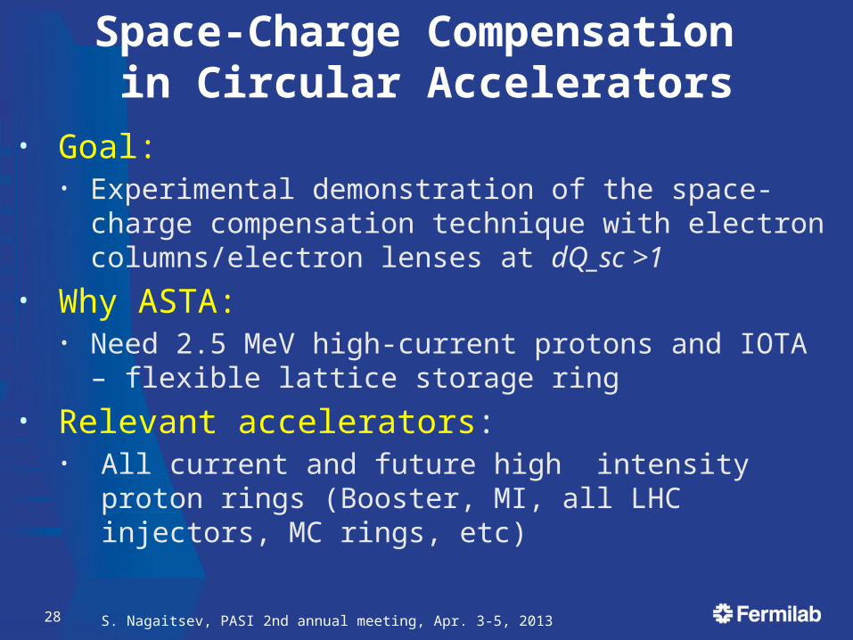
Space-Charge Compensation in Circular Accelerators
• Goal: • Experimental demonstration of the space-charge
compensation technique with electron columns/electron lenses at dQ_sc >1
• Why ASTA: • Need 2.5 MeV high-current protons and IOTA – flexible
lattice storage ring
• Relevant accelerators: • All current and future high intensity proton rings (Booster,
MI, all LHC injectors, MC rings, etc)
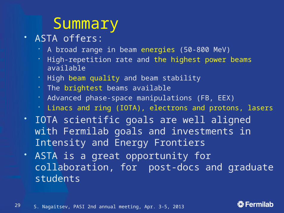
Summary• ASTA offers:
A broad range in beam energies (50-800 MeV) High-repetition rate and the highest power beams available High beam quality and beam stability The brightest beams available Advanced phase-space manipulations (FB, EEX) Linacs and ring (IOTA), electrons and protons, lasers
• IOTA scientific goals are well aligned with Fermilab goals and investments in Intensity and Energy Frontiers
• ASTA is a great opportunity for collaboration, for post-docs and graduate students
S. Nagaitsev, PASI 2nd annual meeting, Apr. 3-5, 201329